

Page 1
AN199
Application Note
DAI Interface for Playing MP3 Music
Introduction
The Maverick family of ARM7 core processors was designed to meet the needs of the "MP3" market to facilitate the
design of a cost-effective digital audio decoder. MP3 is the general name used for this market, which does include
other compressions schemes such as WMA, AAC, and ADPCM.
The Cirrus Logic 7209/12/73XX series microprocessors were all designed to support this market. Each one is
unique, but all possess the necessary hardware to effectively support an "MP3" solution. Each can be used in a
design to play a range of encoded music all based on different compression formats and sample rates.
This note will serve as a guide to initializing the Maverick processor to begin decoding music. Software
decompression is beyond of the scope of the note since it involves a discussion of the compression schemes of the
above mentioned formats.
Due to the changes in the DAI interface, a new hardware configuration is required to insure that the external
CODECs receive the appropriate signals. This is discussed in the hardware interface section.
General Discussion
The DAI (Digital Audio Interface) is the buffering and synchronization mechanism for sending decoded digital
music frames to the external CODEC(s) to be converted into audio. The DAI provides three synchronization clocks
that sync the data, frame by frame, for the external CODEC. The DAI FIFO buffer is eight samples deep and is
always filled with the decoded music frames.
The DAI FIFO controls the branch to the interrupt handler (FIQ). The FIFO can be configured a number of ways,
but based on the state of the FIFO, the FIQ will be triggered at which time the information will be transferred to or
from the FIFO. The information is either played or recorded.
The rule-of-thumb used in our reference player code is an interrupt rate that is ¼ of the sample rate. For a 44.1 kHz
file, the FIQ will be hit at an approximate rate of 11kHz. This is accomplished by configuring the DAI FIQ to assert
whenever the DAI FIFO is half-empty or contains only four frames.
To accomplish this, the DAI machine will need to be initialized properly and the FIQ Handler will need to process
the buffered data correctly. The following discussion will insure the interrupt rate and integrity of the information
passed to and from the DAI.
P.O. Box 17847, Austin, Texas 78760
(512) 445 7222 FAX: (512) 445 7581
http://www.cirrus.com
Copyright 2001 Cirrus Logic (All Rights Reserved) Jun ’01
AN199Rev1
1
Page 2
AN199
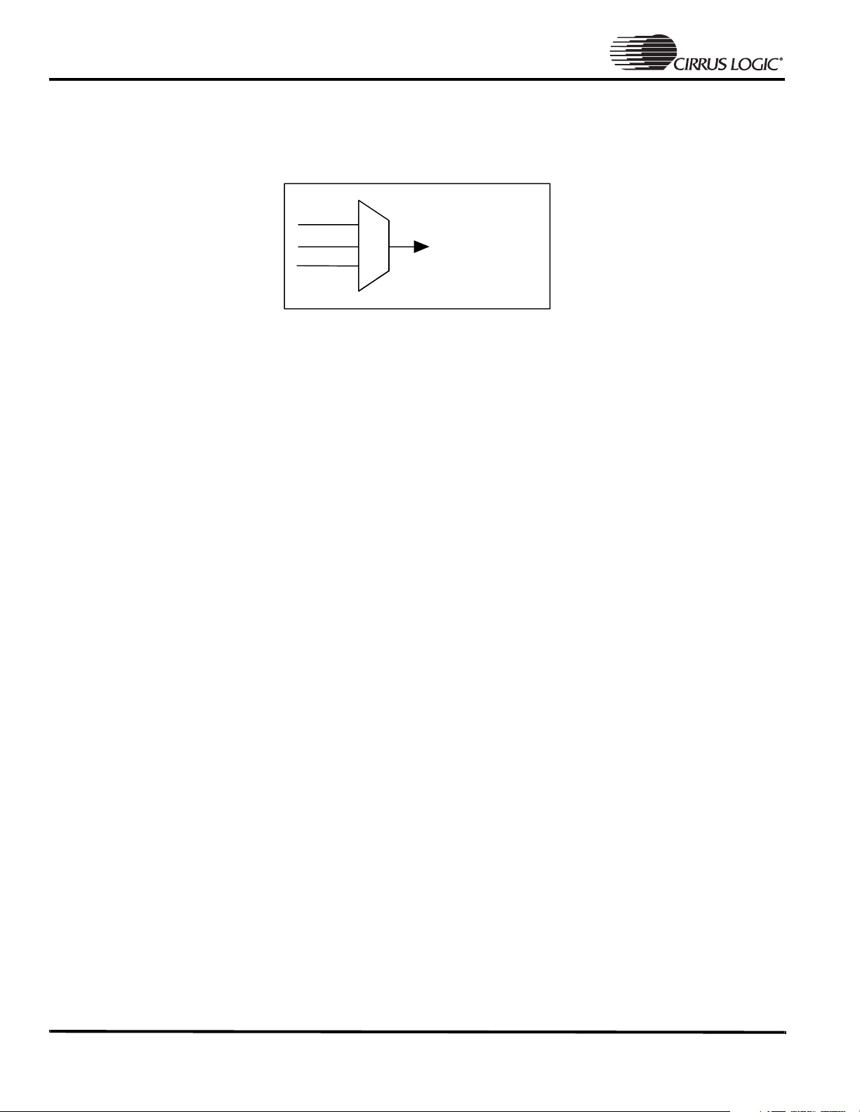
DAI Initialization
The DAI machine shares the output pins with two other devices via an internal MUX. The DAI machine is selected,
output pins are assigned to the machine, then enabled before exiting the routine. See the figure below.
DAI
CODEC
SSI2
SCLK
MCLK
LRCLK
SDIN
SDOUT
• To program the MUX shown above for DAI control, set bit 3 in the System Control Register 3 (SYSCON3).
• If an external clock will generate *MCLK, enable clock.
• The DAI Control Register (DAIR) is programmed with the lower 2 bytes 0404 required. The Right Channel
Transmit FIFO Interrupt Mask (RTCM) is enabled. This is the only interrupt which will call the FIQ for
processing music. External clock source (ECS) bit should also be enabled if external MCLK generator is
used.
• Clear DAI Status Register (DAISR) of any overrun or underrun bits. A write of 0xFFFFFFFF to this location
is sufficient.
• Turn on the DAI by asserting pin 9 of SYSCON3.
• Enable the left and right channel FIFOs in the DAI Data Register 2 (DAIDR2). This will require checking the
DAI status register for each left and right channel enable to make sure the FIFO bit is set.
• Unmask the DAI Interrupt at the DAIINT register. Once unmasked, the DAI FIQ will assert since the RTCM
is already half empty or more and you will immediately enter the FIQ Handler. There is no music to play so
the handler must process the first entry with no data (refer to the FIQ Handler discussion).
Note: *The designer has the option of using an internally generated MCLK or an external MCLK for synchronization with the external
CODECs.
2 Copyright 2001 Cirrus Logic (All Rights Reserved) AN199Rev1
Page 3
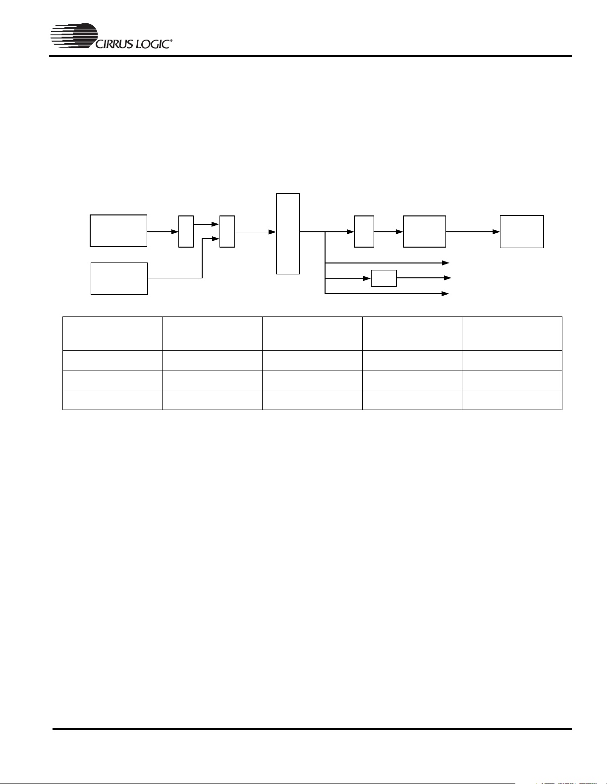
Programming the DAI for the 73xx
The 73xx chips have been enhanced with a DAI interface which allows for MCLK to be clocked at 64Fs
(64 x sampling rate) as well as the traditional 128Fs provided by the 72xx series. There are CODECs on the market
that support 64Fs mode.
The sample rate is also programmable. This allows for greater flexibility in the code design for individual songs
digitized and compressed at different rates. The diagram and table below illustrate the DAI control.
AN199
Programmable Divide
(AUDIV)
MUX
(AUDCLKSRC)
PLL
(73.728MHz)
EXTCLK
(11.2896)
Clock Source
(MHz)
73.728 32 4.0960 2.0480 9
11.2896 44.1 5.6448 2.8224 2
73.728 48 6.1440 3.0720 6
/2
Sample Frequency
(kHz)
128Fs Audio Bit Clock
128/64(Fs)
(MHz)
Digital Audio Clock
Generation
7-bit
/32
Audio Bit Clock 128/64(Fs)
/128
/64
64Fs Audio Bit Clock
counter
fixed at 4
(MHz)
Audio
Sample
Frequency
(Fs)
SCLK
LRCLK(Fs)
MCLK (BUZ)
Audio Data
FIFO
Control
128/64 Divisor
(AUDDIV)
• Either 64Fs or 128Fs must be used for the 73XX. With one selected, the other must be turned off. For 128Fs,
SYSCON3 bit 9 will be set, and bit 0 of the DAI64Fs control register will be cleared. For 64Fs, the converse
must be applied.
• Register DAI64Fs must also be programmed to set the AUDCLKSRC, AUDIV, and to enable or disable 64Fs
mode. MCLK256EN will be enabled. Use the table above or refer to the 73xx User Manual for more detail.
• Settings for 8-24 kHz sample frequencies are not included. The side-effect of using a sample frequency
below 32 kHz is the raising of the noise floor at the external CODEC, thereby increasing the distortion of
the original signal. This issue is external to the processor. In order to decrease noise, samples that fall below
24 kHz sample rate should pass through a sample rate conversion in software to bring it up to a higher rate.
Conversion rates are as follows:
— 8 and 16 kHz to 32 kHz
— 11 and 22 kHz to 44.1 kHz
— 12 and 24 kHz to 48 kHz
AN199Rev1 Copyright 2001 Cirrus Logic (All Rights Reserved) 3
Page 4

AN199
Programming the FIQHandler
MP3, AAC, WMA, etc., libraries decode left and right channel data which will both be stored at some designated
address by the memory buffer. This address will be passed to the FIQ Handler so that data can be moved into the
DAI left and right channel FIFOs.
• IMPORT the address of the buffers to the FIQ routine. This is the decompressed data to be used to fill the
FIFOs.
• If data exists, write 4 samples to each left then right channel in that order until both FIFOs are half- full. The
order here is important. Always start with the left channel and alternate with the right to make certain that
both FIFOs are filled properly.
• If no data exists in the buffers, write four samples of silence to the FIFOs alternating between the left then
right channels. Silence will consist of zeros. There is nothing decoded but the FIFOs are now half-full so the
program can return from the handler and begin processing data.
• Read four samples from the receive buffer regardless of whether there is music to be played or not. If
recording is not taking place at the time, discard the samples, otherwise store them into memory. This will
insure that the DAI FIFO information is in sync. Otherwise the data becomes out of sync and will sound
distorted.
• Clear overrun and underrun status bits in DAI status register in the same manner as mentioned above. This
will insure we avoid an endless loop.
Hardware Interface
Generating MCLK has changed from the EP7212 to the EP7312 microprocessors. This issue is taken separately
since the external hardware implementation is not described in detail in the EP73xx User’s Manual. Due to the
enhancement of the DAI interface for the EP7312, this has lead to additional chip resources required to insure all
signals are present at the external CODECs.
MCLK for the EP7212 is fed by an external oscillator (EXTCLK). That same signal is then passed to the external
CODEC. The clock signals created internally are SCLK and LRCLK. MCLK is simply an input. The EP7212 is
limited to 44.1 kHz sampled files, so the oscillator was fixed to 11.286 MHz or 256Fs. All music files, other than
those sampled at 44.1 kHz, are sample rate converted in software to 44.1 kHz, then sent to the external DAC.
MCLK for the EP7312 is routed differently. Instead of a fixed sample rate, the DAI now allows internal clock
adjustments to provide DAI clocking for all of the standard sample rates. To accommodate this change, MCLK is
now provided by means of the BUZ pin. This can be referred to as MCLK (BUZ) in the User’s Manual, or as
MCLKOUT.
MCLKIN (EXTCLK) is the MCLK signal pin on the DAI interface which can be programmed to receive either an
external clock source or the internal PLL clock as the clock source. The EP7312 64DAIFS register allows the user to
select what clock source will be used. This pin, as with the EP7212, is used as an input.
MCLK (BUZ) or MCLKOUT is also programmable by programming the 64DAIFS register. The signal, when
enabled, will come out on the BUZ pin. Since the BUZ pin is multiplexed with the annuciator, this resource is
dedicated either for that purpose, or for the DAI interface.
The diagram below shows the external hardware connections for MCLK. SCLK, LRCLK, SDTX, and SDRX are not
shown since these signals remain the same across the entire family of processors.
4 Copyright 2001 Cirrus Logic (All Rights Reserved) AN199Rev1
Page 5

MCLK Generation for the
EP7xxx Family
AN199
7312
7212
MCLK
MCLKBUZ
Xtal(EXTCLK)
MCLKMCLK
DAC
DAC
Xtal(EXTCLK)
Conclusion
With the DAI initialization and the FIQ handler routines written correctly, you will achieve an interrupt rate that
will improve the overall performance of the player code. The decoded information will also be shifted to the
CODEC without losing information.
Our reference code, available under NDA, includes a complete initialization routine and interrupt handler which
follows the method described above. This reference code can be used as a template for constructing routines.
Hardware interface examples for both processors are also available. Please contact epdapps@crystal.cirrus.com
more information.
for
AN199Rev1 Copyright 2001 Cirrus Logic (All Rights Reserved) 5
Page 6

AN199
Contacting Cirrus Logic Support
For a complete listing of Direct Sales, Distributor, and Sales Representative contacts, visit the Cirrus Logic web site at:
http://www.cirrus.com/corporate/contacts
Preliminary product information describes products which are in production, but for which full characterization data is not yet available. Advance product information describes products which are in development and subject to development changes. Cirrus Logic, Inc. has made best efforts to ensure that the information contained in this
document is accurate and reliable. However, the information is subject to change without notice and is provided “AS IS” without warranty of any kind (express or implied).
No responsibility is assumed by Cirrus Logic, Inc. for the use of this information, nor for infringements of patents or other rights of third parties. This document is the property
of Cirrus Logic, Inc. and implies no license under patents, copyrights, trademarks, or trade secrets. No part of this publication may be copied, reproduced, stored in a retrieval
system, or transmitted, in any form or by any means (electronic, mechanical, photographic, or otherwise) without the prior written consent of Cirrus Logic, Inc. Items from
any Cirrus Logic website or disk may be printed for use by the user. However, no part of the printout or electronic files may be copied, reproduced, stored in a retrieval
system, or transmitted, in any form or by any means (electronic, mechanical, photographic, or otherwise) without the prior written consent of Cirrus Logic, Inc.Furthermore,
no part of this publication may be used as a basis for manufacture or sale of any items without the prior written consent of Cirrus Logic, Inc. The names of products of Cirrus
Logic, Inc. or other vendors and suppliers appearing in this document may be trademarks or service marks of their respective owners which may be registered in some
jurisdictions. A list of Cirrus Logic, Inc. trademarks and service marks can be found at http://www.cirrus.com.
6 Copyright 2001 Cirrus Logic (All Rights Reserved) AN199Rev1
Page 7

• Notes •
Page 8

 Loading...