

Page 1
AN187
Application Note
USING THE EP72/7312 TO IMPLEMENT A SOFT MODEM
P.O. Box 17847, Austin, Texas 78760
(512) 445 7222 FAX: (512) 445 7581
http://www.cirrus.com
Copyright Cirrus Logic, Inc. 2000
(All Rights Reserved)
OCT ‘00
AN187REV1
1
Page 2

TABLE OF CONTENTS
1. INTRODUCTION ....................................................................................................... 3
2. EP72/7312 DIGITAL AUDIO INTERFACE (DAI) ................................................ 3
3. SI3034 DAA CHIP SET .............................................................................................. 4
4. INTERFACING THE EP72/7312 TO THE SI3034 ................................................. 4
5. PLD EQUATIONS; SOFTMODEM VIA EP72/7312 DAI TO
THE SI3034 DAA CHIP SET ..................................................................................... 8
6. SILICON LABORATORIES CONTACT INFORMATION ............................... 10
LIST OF FIGURES
Figure 1. Example Timing Interface Generated by the DAI............................................... 3
Figure 1. Circuit Schematic................................................................................................. 6
Figure 2. CPLD Schematic ................................................................................................. 7
Figure 2. EP72/7312 to Si3035 Interface Signals.............................................................10
LIST OF TABLES
Table 1. DAA Interface Signals.......................................................................................... 4
Table 2. PLD Equations......................................................................................................8
AN187
Contacting Cirrus Logic Support
For a complete listing of Direct Sales, Distributor, and Sales Representative contacts, visit the Cirrus Logic web site at:
http://www.cirrus.com/corporate/contacts/sales.cfm
Preliminary product inf o rmation describes product s whi ch are in production, b ut for which full character iza t i on da t a i s not yet available. Advance p roduct information describes products which are in development and subject to development changes. Cirrus Logic, Inc. has made best efforts to ensure that the information
contained in this document is accurate and reliable. However, the information is subject to change without notice and is provided “AS IS” without warranty of any
kind (express or imp lied ). N o r espo ns ibility is a ss ume d b y Cirru s Logic, Inc. for the use of this information, nor for infringements of patents or other rights of third
parties. This document is the property of Cirrus Logic, Inc. and implies no license under patents, copyrights, trademarks, or trade secrets. No part of this publication may be copied, reproduced, stored in a retrieval system, or transmitted, in any form or by any means (electronic, mechanical, photographic, or otherwise)
without the prior written consent of Cirrus Log ic, In c. Items from any Cirrus Logic web si te or disk may be printe d for use by the user. However, no part of the
printout or electronic files may be copied, reproduced, stored in a retrieval system, or transmitted, in any form or by any means (electronic, mech ani cal , photo graphic, or otherwise) without the pr i or wri t ten consent of Cirrus Logic, Inc.Furtherm ore, no part of this p ubl i cat i on may be used as a basis for manufacture or
sale of any items without the pri or written consent of Cir rus Lo gi c, Inc. Sil i con Laboratories is a trademark of Silicon Laboratories, Inc. AltoCom is a tra dema r k
of AltoCom, Inc. Lattice Semiconductor is a trademark of Lattice Semiconductor Corporation. The names of products of Cirrus Logic, Inc. or other vendors and
suppliers appearing in t his document may be tradema rks or service m arks of their r espective owner s which may b e registered i n some jurisdi ctions. A list of
Cirrus Logic, Inc. trademarks and service marks can be found at http://www.cirrus.com.
2 AN187REV1
Page 3
AN187
1. INTRODUCTION
As the world of PDAs and other hand-held devices evolves, more and more of these products desire the support of an analog
modem to communicate with the Internet. Today, the use of modems constitutes only a small market share. However, the desire
for modem support is growing dramatically. Due to this fact, this application note has been created.
This application note describes how the ARM720T™ processor, DRAM controller, and the Digital Audio Interface (DAI)
integrated into the Cirrus Logic EP72/7312 embedded processor can be used to implement a V.90 softmodem solution.
Used in conjunction with the EP72/7312 are the following components:
n V.90 softmodem and driver code
n Silicon Laboratories™ Si3034 DAA chip set
n A simple PLD, used to implement the interface logic between the DAI and the Si3035 chip set.
Schematics and a timing diagram are provided to explain the characteristics of this interface.
2. EP72/7312 DIGITAL AUDIO INTERFACE (DAI)
Within the EP212 is an integrated Digital Audio Interface (DAI). This interface was implemented to support high quality stereo
audio transmission and reception. However, it can be used to support other functions, like a softmodem. The interface consists
of five signals:
n LRCK Left/right frame sync; output only
n SCLK Bit clock; equals ½ MCLK; there are 128 bits-per-frame; output only
n MCLK 2x oversampled clock; input when in Slave mode
n SDOUT Digital audio data out; output
n SDIN Digital audio data in; input
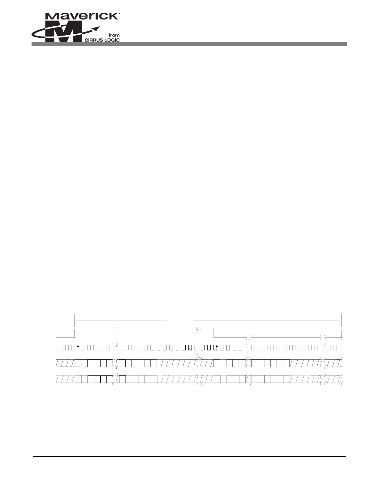
An example of the timing interface generated by the DAI for a typical audio application is shown in Figure 1.
The data uses the MSB/Left Justified format. This means that the data is clocked in/out immediately after the frame sync
(LRCK) changes levels. The data is left ju stified, with the MSB first. This is sl ightly different than the I2S format, where th e
data is delayed by one clock after the frame sync changes levels. Each frame is 128 bits long. Thus each channel (i.e., left and
right) is 64 bits wide. The frame size and duty cycle of the signal LRCK cannot be configured in the EP72/7312. 'The frame
size in the EP7312 can be configured for either 128 or 64 bits per frame, but this is not relevent for this application.
128 clocks
LRCK
SCLK
O
SDATA +3 +2 +1 LSB+5 +4
SDATA +3 +2 +1 LSB+5 +4
SDATAI +3 +2 +1 LSB+5 +4MSB-1-2-3-4-5 +3 +2 +1 LSB+5 +4MSB-1 -2 -3 -4
MSB-1-2-3-4-5
MSB-1-2-3-4-5
Left Channel
MSB-1 -2 -3 -4
MSB-1 -2 -3 -4
Right Channel
+3 +2 +1 LSB+5 +4
+3 +2 +1 LSB+5 +4
Figure 1. Example Timing Interface Generated by the DAI
Figure 1 Parameters: MSB/Left Justified format
Mclock = 256
, bit rate = 128
fs
fs
AN187REV1 3
Page 4
AN187
SCLK is derived from MCLK. It is ½ MCLK. In the default mode, the DAI is in the Master mode. In this mode it generates its
own MCLK clock. It is 9.216 MHz. Thus SCLK becomes 4.608 MHz. For applications that need SCLK to be different speed,
the DAI can be configured to be in the Slave mode. In this mode, MCLK is provided from an external source via the MCLK
pin. When in the Slave mode, the DAI will receive its master clock from the MCLK pin, and then divide it in half to create
SCLK. In this application of the softmodem, we will need to use this Slave mode, and provid e a 4.096 MHz clock sour ce into
the MCLK pin. SCLK and LRCK are always configured as outputs regardless of the DAI mode setting. The data is latched in
on the positive going edge of the SCLK, and is clocked out on the negative going edge.
3. SI3034 DAA CHIP SET
The Silicon Laboratories Si3034 is an integrated Direct Access Arrangement (DAA) that provides a programmable line
interface to meet global telephone line interface requirements. Programmable features inclu de AC and DC terminations, ringer
impedance and ringer threshold. Also supported is bil ling tone detection, polarity reversal, pulse dialing, and on-hook line
monitoring. Available in two 16-pin small outline packages, it eliminates the need for an analog front-end (AFE), an isolation
transformer, relays, opto-isolators, and a 2- to 4-wire hybrid circuit. This Si3034 chip set runs at either 3.3v or 5V, and
dramatically reduces the number of discrete external components required to achieve compliance with global regulatory
requir.ements. If only compliance to North American and Japanese standards are required, the Si3035 DAA may be used instead
of the Si3034 global DAA
The DAA communication interface consists of the signals described in Table 1.
NOTE: There are other signals on the DAA as well. Please refer to the
ation and configuration.
The Si3034/35 transfers data in a 16-bit h alfword format. D ata is transf erred using the sam e MSB/Left J ustified format as the
EP72/7312's DAI. It uses a 256-bit frame size. In this 256-bit frame are two 128-bit-long time slots: primary and secondary.
The two time slots are delineated by the rising edge of nFSYNC. Thus nFSYNC toggles twice per frame. The primary time slot
is used to transfer telephony data. The secondary time slot is used as a control channel between the Host and the DAA. It can
be used to change the default configuration settings of the chip set. Refer to the Si3034 or the Si3035 Data Sheet for more
information.
The data is latched on the negative going edge of SCLK, and is clocked out on the positive going edge. This is the opposite of
the DAI.
NOTE: Carefully follow the instructions in the
in your system design.
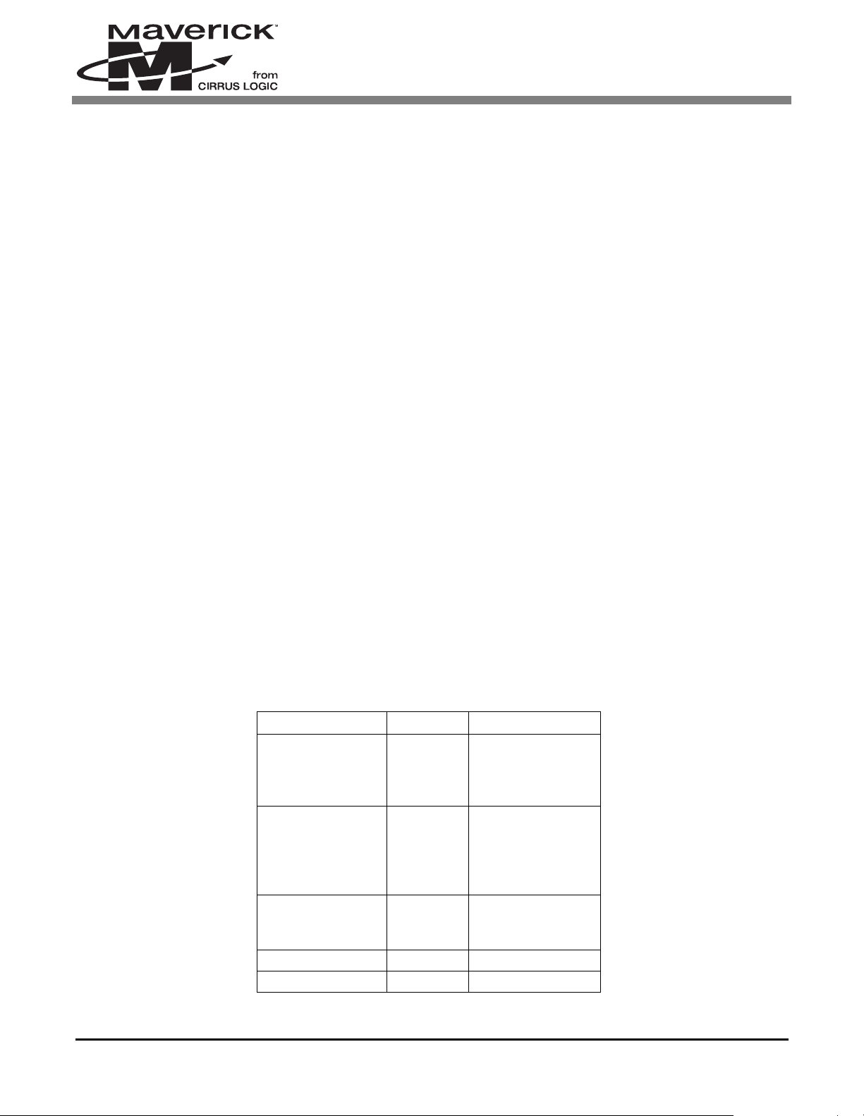
Signal Name Purpose Activity
nFSYNC Frame Sync Output in Master
SCLK Bit Clock Output when in
Si3034/35 Data Sheet
mode, input in
Slave mode
Master mode, no
connect in Slave
mode
Si3034
to program and implement the device properly
or
Si3035 Data Sheet
for their oper-
MCLK Master
clock
SD0 Data out
SDI Data in
Table 1. DAA Interface Signals
4 AN187REV1
1x SCLK, used as
input to create bit
clock
Page 5

AN187
4. INTERFACING THE EP72/7312 TO THE SI3034
The EP7312 can generate a 4.096 MHz internal clock. But, in the EP7212, the DAI interface can only provide a fixed internal
clock source of 9.216 MHz when in Master mode. Because this is incompatible with the clock rate needed by the DAA, the DAI
has to be configured for Slave mode. An external clock source of 4.096 MHz is thus connected to the DAI MCLK pin, which
internally will be halved to create its SCLK. Since the DAI and DAA logic need to be synchronized, SCLK outputting from the
DAI can be used (after inverted) as the MCLK input into the DAA.
For the modem to support the V.90 protocol it needs to transfer each sample of data at a rate of 8 kHz. This means that each
frame must be transferred at this rate. Since the frame size of the DAA is 256 bits-per-frame, this equates to a bit rate of 2.048
MHz. Therefore, a clock source of 2.048 MHz should b e connected to the MC LK pin of the DAA. In order to achieve the correct
frame rate from a 2.048 MHz MCLK input, the DAA also needs to be configured in Slave mode.
With the DAA running in Slave mode, MCLK and nFSYNC have to be supplied to the DAA. It has already been stated above
how MCLK gets created, however no w th e creat ion of nF SYNC need s t o be d iscus s ed. Th e nF SY NC si gnal requires nFSYNC
to be low during the 16 bit data transfer, and high all other times. This does not comply with the I2S like interface. So a circuit
has been created to shape the frame sync signal generated by the DAI (i.e. LRCK), to meet the timing requirements of the frame
sync signal input required by the DAA (i.e. nFSYNC). This circuit counts 16 bit cycles after LRCK goes high, and forces the
created nFSYNC signal high after these 16 cycles. It keeps nFSYNC high, until LRCK goes high again. This circuit has been
implemented using a low cost small CPLD. The Lattice ispMACH 4A CPLD (exact part number: M4A3-32/32-10VC) device
is used. To meet the setup time spec of the internal D-FFs, LRCK must be delayed. This is accomplished by using two spare
74LVX14 inverters in series with LRCK prior to it entering the CPLD.
In high volume (500k), the device is between 50 cents and $1.00.
To allow for the lowest speed ispMACH device (i.e., 10ns), SCLK created for the DAA is delayed through the CPLD. This
allows the critical spec for the DAA (i.e., Td1 and Td 2; Delay Time, SCLK high to nFSYNC high, and SCLK high to nFSYNC
low, respectively) to be met easily. The resulting signal is called SCLK_DLYD. I t should be connected to the DAA’s MCLK pin.
A schematic breakdown of the entire circuit is provided in Figure 1, “Circuit Schematic,” on page 6. The schematics for the
CPLD only is shown in Figure 2, “CPLD Schematic,” on page 7.
NOTE: It is required to connect nSCLK to two separate input pins on the CPLD: 1). The input clock, and 2). A gen-
eral purpose input. This was nece ssary to be a ble to route nSCL K in and out of the device to create the
signal SCLK_DLYD.
The CPLD equations compiled from the schematics are provided in , and the timing diagram is provided in Figure 3,
“EP72/7312 to Si3035 Interface Signals,” on page 10. The user should read carefully through the ispMACH Data Sheet to
program and implement the device properly in the system design.
AN187REV1 5
Page 6

6 AN187REV1
Figure 1. Circuit Schematic
AN187
Page 7

7 AN187REV1
nSCLK
LRCK_DLYD
I4
DQ
I17
11
I22
I6
nSCLK
27
I11
_also
I21
DQ
I18
18
I24
I12
I7
6
I13
SCLK_DLYD
I23
I3
DQ
I19
I5
I10
DQ
I16
I8
Figure 2. CPLD Schematic
I9
I14
DQ
I2
3
I15
nFSYNC
I20
AN187
Page 8

5. PLD EQUATIONS; SOFTMODEM VIA EP72/7312 DAI TO THE SI3034 DAA CHIP SET
AN187
P-Terms Fan-in Fan-out Type Name
(attributes)
1/1 1 1 pin SCLK_DLYD SCLK_DLYD = (N_22)
Reverse Polarity — !SCLK_DLYD = (!N_22)
1/1 1 1 pin nFSYNC nFSYNC = (N_20)
Reverse Polarity — !nFSYNC = (!N_20)
1/1 1 1 node N_21 N_21 = (nSCLK)
Reverse Polarity — !N_21 = (!nSCLK)
1/1 1 1 node N_22 N_22 = (nSCLK_also)
Reverse Polarity — !N_22 = (!nSCLK_also)
1/1 1 1 node N_19 N_19 = (LRCK_DLYD)
Reverse Polarity — !N_19 = (!LRCK_DLYD)
2/1 1 1 node N_20 N_20 = (N_17 # !N_19)
Reverse Polarity — !N_20 = (!N_17 & N_19)
2/2 2 1 node N_1 N_1 = (N_15 & !N_13 # !N_15 & N_13)
Reverse Polarity — !N_1 = (!N_15 & !N_13 #
N_15 & N_13)
1/2 2 1 node N_2 N_2 = (N_15 & N_13)
Reverse Polarity — !N_2 = (!N_15 # !N_13)
1/2 2 1 node N_3 N_3 = (N_19 & N_1)
Equations
Reverse Polarity — !N_3 = (!N_19 # !N_1)
2/2 2 1 node N_4
1/2 2 1 node N_5 N_5 = (N_19 & N_4)
2/1 2 1 node N_6
1/4 4 1 node N_7 N_7 = (N_16 & N_15 & N_13 & N_12)
1/2 2 1 node N_8 N_8 = (N_19 & N_6)
Table 2. PLD Equations
N_4 = (N_2 & !N_16 # !N_2 & N_16)
Reverse Polarity — !N_4 = (!N_2 & !N_16
# N_2 & N_16)
Reverse Polarity — !N_5 = (!N_19 # !N_4)
N_6 = (N_7 # N_17)
Reverse Polarity — !N_6 = (!N_7 & !N_17)
Reverse Polarity — !N_7 = (!N_13 # !N_15
# !N_16 # !N_12)
Reverse Polarity — !N_8 = (!N_19 # !N_6)
8 AN187REV1
Page 9

AN187
P-Terms Fan-in Fan-out Type Name
(attributes)
2/2 2 1 node N_9
1/2 2 1 node N_10 N_10 = (N_19 & N_9)
1/3 3 1 node N_11 N_11 = (N_16 & N_15 & N_13)
1/1 1 1 node N_12.D N_12.D = (N_10)
1/1 1 1 node N_12.C N_12.C = (N_21)
1/1 1 1 node N_13.D N_13.D = (N_14)
1/1 1 1 node N_13.C N_13.C = (N_21)
1/2 2 1 node N_14 N_14 = (!N_13 & N_19)
N_9 = (N_11 & !N_12 # !N_11 & N_12)
Reverse Polarity — !N_9 = (!N_11 & !N_12 #
N_11 & N_12)
Reverse Polarity — !N_10 = (!N_19
# !N_9)
Reverse Polarity — !N_11 = (!N_15 # !N_16 #
!N_13)
Reverse Polarity — !N_12.D = (!N_10)
Reverse Polarity — !N_12.C = (!N_21)
Reverse Polarity — !N_13.D = (!N_14)
Reverse Polarity — !N_13.C = (!N_21)
Equations
1/1 1 1 node N_15.D N_15.D = (N_3)
1/1 1 1 node N_15.C N_15.C = (N_21)
1/1 1 1 node N_16.D N_16.D = (N_5)
1/1 1 1 node N_16.C N_16.C = (N_21)
1/1 1 1 node N_17.D N_17.D = (N_8)
1/1 1 1 node N_17.C N_17.C = (N_21)
33/42
Best P Term
Total: 31
Total Pins: 5
Total Nodes: 21
Average P-
Term/Output: 1
Reverse Polarity — !N_14 = (N_13 # !N_19)
Reverse Polarity — !N_15.D = (!N_3)
Reverse Polarity — !N_15.C = (!N_21)
Reverse Polarity — !N_16.D = (!N_5)
Reverse Polarity — !N_16.C = (!N_21)
Reverse Polarity — !N_17.D = (!N_8)
Reverse Polarity — !N_17.C = (!N_21)
Table 2. PLD Equations (Continued)
AN187REV1 9
Page 10

nFSYNC
s
s
s
AN187
16 cycle
64 cycle
LRCK
LRCK_DLYD
SCLK
nSCLK
SDOUT
SDIN
D15 D14 D1 D0
D15 D14 D1
Figure 3. EP72/7312 to Si3035 Interface Signals
6. SILICON LABORATORIES CONTACT INFORMATION
64 cycle
Silicon Laboratories, Inc.
4635 Boston Lane
Austin, Texas 78735
Phone: 1-877-444-3032
Email: SiDAAinfo@silabs.com
Web site: www.silabs.com
10 AN187REV1
Page 11

• Notes •
Page 12

 Loading...