

Page 1

Application Note
BRINGING UP THE EP72/73XX DEVICE
AN186
Note: Cirrus Logic assumes no responsibility for the attached information which is
provided “AS IS” without warranty of any kind (expressed or implied).
P.O. Box 17847, Austin, Texas 78760
(512) 445 7222 FAX: (512) 445 7581
http://www.cirrus.com
Copyright Cirrus Logic, Inc. 2000
(All Rights Reserved)
OCT ‘00
AN186REV1
1
Page 2

TABLE OF CONTENTS
1. INTRODUCTION .......................................................................................................................3
2. THE SUPPORTED POWER MANAGEMENT STATES ........................................................... 3
3. THE DEGLITCHER ...................................................................................................................3
4. WAKEUP DELAYS ................................................................................................................... 3
4.1 Power-up Delay - 100us ....................................................................................................4
4.2 1 to 2 Second Delay .......................................................................................................... 4
4.3 Manual WAKEUP Signal Generation ................................................................................. 5
4.3.1 Automatic WAKEUP Signal Generation ................................................................5
5. LOCK-OUT PERIOD DELAYS ................................................................................................. 6
5.1 Rationale behind the Lock-out Period Delays .................................................................... 6
6. THE FUNCTION OF "RUN/CLKEN" OUTPUT PIN AS IT RELATES
TO WAKEUP OPERATIONS ......................................... ...... ....................................... ....... ..... 6
7. WAKEUP AND NURESET CAVEAT ........................................................................................ 7
8. TIMING DIAGRAMS ................................................................................................................. 8
8.1 Timing Diagram in the case of a Cold Boot .......................................................................8
8.2 Timing Diagrams for the Case of Wakeup from Standby State .........................................9
9. AUTOMATIC WAKEUP CIRCUIT ..........................................................................................11
AN186
LIST OF FIGURES
Figure 1. EP72/73XX Power Management States .......................................................................... 3
Figure 2. Example Circuit for Keeping nURESET Inactive during Prescribed Period.....................7
Figure 3. Timing Diagram for the Case of a Cold Boot ...................................................................8
Figure 4. Timing Diagram, External OSC(13 MHz) with “CLKEN” on ‘”RUN/CLKEN” Pin..............9
Figure 5. Timing Diagram, External OSC (13 MHz) with “RUN” on “RUN/CLKEN” Pin.................. 9
Figure 6. Timing Diagram, PLL Clock with “CLKEN” on “RUN/CLKEN” Pin .................................10
Figure 7. Timing Diagram, PLL Clock with “RUN” on “RUN/CLKEN” Pin .....................................10
Figure 8. Automatic Wakeup Circuit..............................................................................................11
LIST OF TABLES
Table 1. Wakeup Delays ................................................................................................................. 6
Contacting Cirrus Logic Support
For a complete listing of Direct Sales, Distributor, and Sales Representative contacts, visit the Cirrus Logic web site at:
http://www.cirrus.com/corporate/contacts/sales.cfm
Preliminary product inf o rmation describes products whi ch are in production, b ut f or wh i ch ful l characterization data i s not yet available. Advance product information describes products which are in development and subject to development changes. Cirrus Logic, Inc. has made best efforts to ensure that the information
contained in this document is accurate and reliable. However, the information is subject to change without notice and is provided “AS IS” without warranty of any
kind (express or imp lied ). N o re spon sib ility is as sume d b y Cirrus Logic, Inc. for the use of this information, nor for infringements of patents or other rights of third
parties. This document is the property of Cirrus Logic, Inc. and implies no license under patents, copyrights, trademarks, or trade secrets. No part of this publication may be copied, reproduced, stored in a retrieval system, or transmitted, in any form or by any means (electronic, mechanical, photographic, or otherwise)
without the prior written consent of Cirrus Log ic, In c. Items from any Cirrus Logic web si te or disk may be printe d for use by the user. However, no part of the
printout or electronic files may be copied, reproduced, stored in a retrieval system, or transmitted, in any form or by any means (electronic, mech ani cal , photographic, or otherwise) without the pr i or wri t ten consent of Cirrus Log ic, Inc.Furthermore, no part of this publi c ati on may be used as a basis for manufacture or
sale of any items without the prior written consent of Cirrus Logic, Inc. The names of products of Cirrus Logic, Inc. or other vendors and suppliers appearing in
this document may be trademarks or servi ce marks of their re specti ve owners which may be reg istered in some jur isdict ions. A list of Cirrus Logic, Inc. trademarks and service marks can be found at http://www.cirrus.com.
2 AN186REV1
Page 3
AN186
1. INTRODUCTION
This application note des cribes i n detail t he recomm ended pro cedure for apply ing power to th e EP72/73 XX device, an d how to
transition from the Standby State into the Operating State.
2. THE SUPPORTED POWER MANAGEMENT STATES
The EP72/73XX supports the following Power Management States:
l Operating — The normal program Execution State is the Operating State; this is a full performance State where all of
the clocks and peripherals are enabled.
l Idle — The Idle State is the same as the Operating State with the exception of the CPU clock being halted. An interrupt
will return it back to the Operating State.
l Standby — The Standby State has the lowest power consumption; selecting this state shuts down the main oscillator,
leaving only the Real Time Clock (R TC) and its associated logic powered. When the EP72/73XX is in the S tandby State,
the device is basically turned “off.” Only the WAKEUP pin or interrupt source can wake up the device.
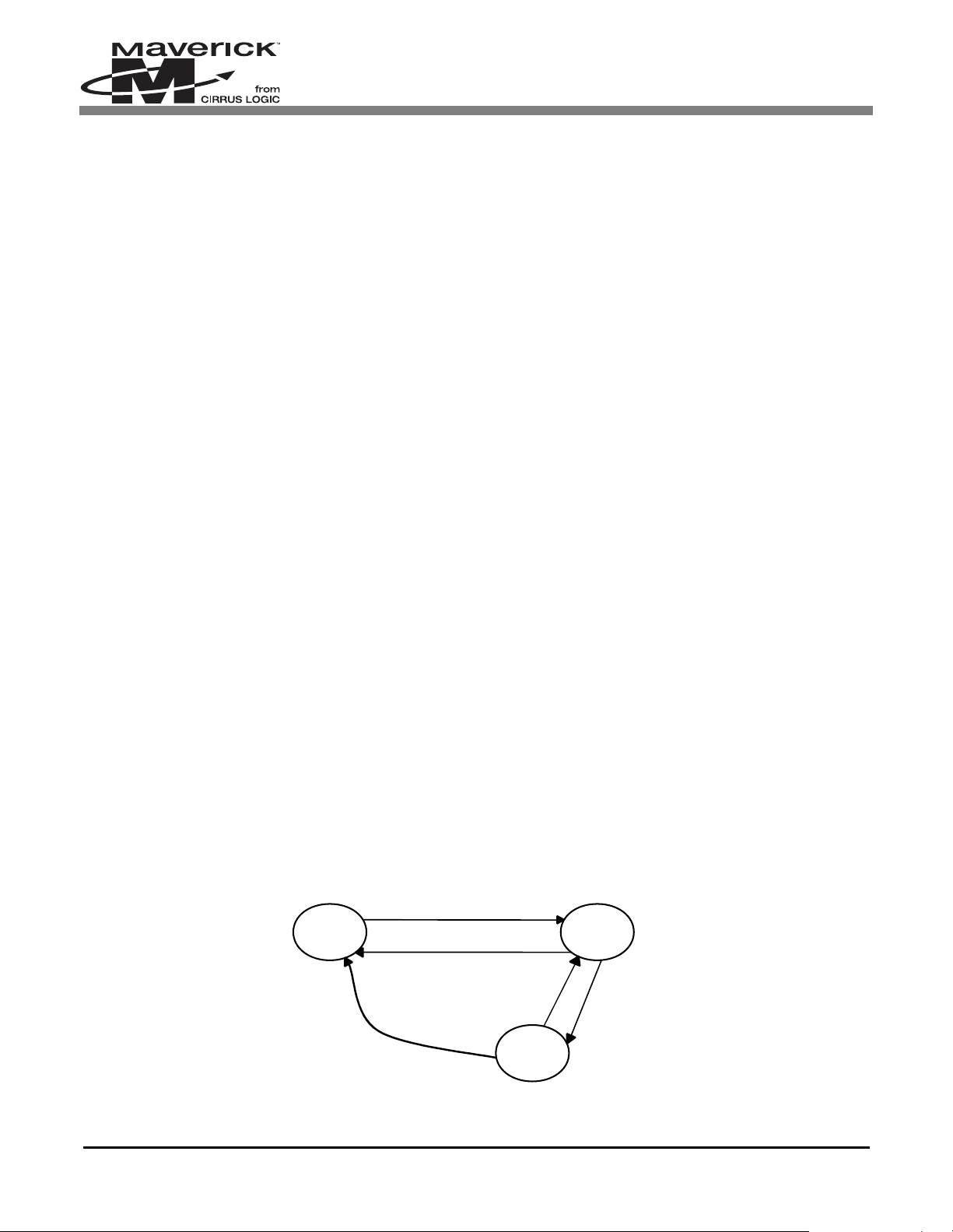
See Figure 1 to see the interactions between the power management states.
Note: The WAKEUP signal is only used to exit the Standby State, not the Idle State. The only state that the
Standby State can transition to is the Operating State.
3. THE DEGLITCHER
Built into the EP72/73XX are six identical conditio ning circuits. They are designed to deglitch the following six sig nals:
l WAKEUP
l nBATCHG
l nPWRFL
l nURESET
l nMEDCHG
l Low Battery Interrupt (combination of BATOK, nEXTPWR and the internal RUN signal).
For any of the above signals to become active internal to the EP72/73XX, they must first be deglitched. Each deglitcher is simply
two D Flip Flops in series configured so that the input signal must be held active (HIGH) for a minimum of two clock edges.
The clock source is derived from the RTC. It is ½ the RTC frequency (i.e., ½ of 32.768 kHz = 16.384 kHz). The deglitcher
performs two tasks:
1) No input signal will pass through it, unless it is held active for at least two clock edges.
2) It guarantees that the output signal from the deglitcher will be active for a minimum of ~ 62us (i.e., 1/16.384 kHz).
4. WAKEUP DELAYS
The EP72/73XX device has several different time delays that may occur when powering up and/or exiting the Standby State.
The sections below describe them all.
Interrupt or Rising Wakeup
STANDBY
OPERATING
Write to Standby Location,
Low Battery, or User Reset
INTERRUPT
nPor, Low Battery,
or User Reset
Figure 1. EP72/73XX Power Management States
AN186REV1 3
IDLE
Write to Halt
Location
Page 4

AN186
4.1 Power-up Delay - 100us
Upon power-up, the EP72/73XX is in an unknown state. It must first be reset by the power -on reset signal (nPOR). n POR (active
low) should be held low until the power supply reaches its operational voltage to initialize the EP72/73XX pr operly, and to allow
the RTC to stabilize. Since the power-on reset o perates asy nchro nously to the s ystem clo ck, i t is not requ ired to w ait unt il the
system clock is stabilized. Therefore, the signal nPOR must be held low at 100us after the power supply has stabilized.
Afterwards, nPOR should be held high.
During normal operation (i.e., after the initial power-up) if nPOR is used to reset the EP72/73XX, it needs to be held low for at
least one clock cycle of the selected clock speed (e.g., when running at 13 MHz, the low pulse width needs to be > 1/13 MHz
= 77 ns). This is done to guarantee that it will be detected low.
If the EP72/73XX V
guarantee that all internal logic is in a known state. This especially applies to the internal State Control logic block. This logic
block must be reset to guarantee proper operation of the device. To fully reset the device, nPOR must be used. The signals
nPWRFL and nURESET do not reset the State Control block.
When nPOR transitions from a low to high state, it latches several signals into the EP72/73XX. These signals are the following:
l Test[0:1]
l Port E[0:2]
l nURESET
l DRIVE[0:1]
l nMEDCHG
Since the levels of each of the above signals are latched upon nPOR rising, they need to have settled to their desired level. The
recommended method of accomplishing this is by tying each of the signals directly to V
or low. Test[0:1] and nURESET are latched upon reset to determine if the EP72/73XX should enter a Test mode upon powerup. For normal operation, all three signals should be either tied or pulled high. See the product data sheet for a description of
each of the other signals.
core supply ever drops below the DC recommended operating range, the device must be fully reset to
dd
or gnd, or by pulling them either high
dd
4.2 1 to 2 Second Delay
A power-up or cold boot delay occurs when power is first applied to the EP72/73XX. However, it can also occur after a battery
change or power failure. A power failure could occur due to the battery or wall powered supply voltage dropping below a
predefined level.
Built into the EP72/73XX is a circuit that has been created to prev ent the EP72/ 73XX from exi ting the Stan dby State due to a
false battery GOOD indication caused by alkaline battery recov ery. The circuit r equires th at the p ower supply voltage be at the
acceptable level for at least one second. The EP72/73XX implements this by conditioning several signals into another
deglitcher. This deglitcher is clock ed by a 1 Hz clock so urce, deriv ed from the R TC. Therefore, the po wer to t he EP72/73 XX
must be stable for at least 2 seconds (i.e., a minimum of two 1 Hz clock edges). Th e signals su ppli ed to this d eglitch er are the
following:
l nPOR
l nPWRFL
l BATOK
l nEXTPWR
In order for the output of this deglitcher to become active, it must have the signals nPOR and nPWRFL = 1, and either BATOK
= 1 or nEXTPWR = 0.
After the above criteria is met, there are two methods that can be used to exit the Standby State:
1) By using the WAKEUP signal, or
2) By receiving a keypress, RTC, external, or media change interrupt. In order for this to work, the KBWEN bit must be
set in the SYSCON2 register.
4 AN186REV1
Page 5

AN186
Notes: 1. The use of the keypress interrupt is disabled after any of the three available resets become active (i.e.
nPOR, nURESET, or nPWRFL) due to the fact that the KBWEN bit is cleared by default. Therefore, a
keypress cannot wake-up the device after a cold boot or power fail.
2. When the EP72/73XX is in the Standby State, the nPWRFL signal is disabled. It cannot be used to reset
the device.
At any time, if nPOR or nPWRFL become active, or BATOK and nEXTPWR both become inactive, the EP72/73XX will
require this two second delay before it can exit the Standby State, after all of these signals return to their normal operating state.
After the EP72/73XX has been reset by nPOR, the device will transition into the Standby State. The only method that can be used
to exit the Standby State is b y the device detecting the W AKEUP signal transitioning from a low to high. Ho wever, the EP72/73XX
has the 2 second fixed delay before it can detect this transition. Therefore, if the WAKEUP signal rises prior to this delay
expiration, it will be ignored. It will have to go low and high again once the delay period has expired.
When the EP72/73XX is not in the Standby State, if BATOK and nEXTPW R both becom e inactive, the EP72/7 3XX will not
enter the Standby State immediately. Rather, they simply will generate an interrupt (BLINT in the INTSR1 register). Therefore,
action taken by this interrupt is so lely d etermined by software. For ex ample: this in terrupt could be u sed to sen d a m essage to
the display informing the user that the battery needs to be changed. After a period of time, the software could then decide to
force the device into the Standby State by writing to the STDBY register.
4.3 Manual WAKEUP Signal Generation
There are numerous methods of creating the WAKEUP signal. If it is desired to force the user to perform some form of intervention
to wake up the device; here is one possible approach when a keypad is used with the Column drive and the Port A row pins. By
default upon power-up, the Col[x] pins are all driven high and the Port A[x] pins are all configured as inputs. Route a key so that
one terminal is connected to one of the Col[x] pins, and the other terminal is connected to one of the Port A[x] pins. Connect the
Port A[x] pin to the WAKEUP pin. Connect a 47k pull-dow n resistor to this node. Wh en the key is pressed that is tied to Port A[x],
it will cause this node to go high. Since it is connected to the WAKEUP pin, it was also cause the WAKEUP signal to go high,
thus waking up the EP72/73XX. Two factors are assumed here: 1). The key will not be pressed until two seconds after the prod uct
is powered-up, and 2). The key will be depressed for longer than 125us. It should be easy to comply with both of these factors.
After the EP72/73XX has entered the Operating State, the WAKEUP signal is ignored, and thus it will not have any affect on
the EP72/73XX if the key is used in a normal manner. If the product re-enters the Standby State due to software control, this
key can be used to re-wake the product. If it is desired to disab le this key from al lowing the pro duct to re-exi t the Standby State,
then its WAKEUP functionality can be d isabled by forcing th e WAKEDIS bit h igh in the SY SCO N1 reg ister. This will cause
the EP72/73XX to ignore any activity on the WAKEUP pin. It will be ignored until the EP72/73XX is reset or the software
clears the WAKEDIS bit.
4.3.1 Automatic WAKEUP Signal Generation
If it is desired to implement a design that will force the EP72/73XX to automatically enter the Operating State upon power-up,
it is possible to create a simple square wave generator whose output becomes the WAKEUP signal. The period of each cycle
must be greater than 2 x 125us = 250us. Thus this signal can be used to automatically wake up the EP72/73XX.
While in the Operating and Idle States, the WAKEUP signal is ignored. Therefore, it can continue to toggle without any effect.
However, if the EP72/73XX is forced back into the Standby State, it would immediately re-wake, unless somehow this external
WAKEUP signal has been disabled. Two methods are available:
The first method uses the software to set the WAKEDIS bit after the EP72/73XX has entered the Operating State. This will
disable the WAKEUP signal from immediately forcing the EP72/73XX out of the Standby State, when forced to do so by the
software. However, this approach does have one drawback. When the WAKEDIS bit is set, it also prevents the device from
being wakened by a keypress after a power fail indication or battery change occurs.
If you want to have the ability to wake th e device with a keypress, then an external W AKEUP signal disabler must be implemented.
This can easily be done by adding a two input NOR gate in series wi th the output of the square wave generator. One of the inputs
into the NOR gate is the output of the square wave generator. The other is an unused GPIO pin. The GPIO pin should have a
pulldown on it to prevent it from floating upon power-up. After the EP72/73XX has entered the Operating State, program this
GPIO pin so that it forces it high. This will cause the output of the NOR to go low. Use the output of this NOR gate as the input
into the WAKEUP pin. See the Figure 8, “Automatic Wakeup Circuit,” on page 11.
AN186REV1 5
Page 6

AN186
5. LOCK-OUT PERIOD DELAYS
These delays can be described as the amount of delay from when the WAKEUP signal first rises, until the CPU starts fetching
instructions. There are two cases of these wakeup delays in the EP72/73XX. One case is the cold boot that can happen after
power-up, in changing a battery, or a power failure. The second instance occurs after software has forced the device into the
Standby State. In both cases, the internal system cl ock is turned off t o save power consumption. To resume the normal operation
upon receiving the WAKEUP signal, the system has to wait until the system clock is stabilized. This waiting period is defined
as the Lock-out Period.
The internal system clock is controlled by an internally generated signal (Internal RUN), which is activated by the wakeup
source with a predefined delay time (lock-out period delay). This delay will ensure the clock source is stabilized before the
internal system clock is turned on. When the internal system clock starts running, the device resumes the normal operation in
which instructions are executed.
5.1 Rationale behind the Lock-out Period Delays
The amount of the lock-out period delay has been hardwired internally to ensure that enough time has elapsed for the clock
source to be stable before the clock to the CPU is enabled. It also varies depending upon the source of system clock (external
oscillator or internal PLL). In a system that is designed to use the internal PLL or the oscillator with an enable / disable feature,
it takes some time (a few hundred ms) to establish a stable clock o utput after powering on the PLL or the external o scillator.
Therefore, the internal system clock enable signal (Internal RUN) should wait a longer time than in the case when the oscillator
is always running. The specific wakeup delays are tabulated in Table 1.
6. THE FUNCTION OF "RUN/CLKEN" OUTPUT PIN AS IT RELATES TO WAKEUP OPERATIONS
There is a multipurpose output pin named “RUN/CLKEN”. The function of the pin is determined by one bit (CLKENSL) in the
SYSCON2 register. When CLKENSL = 0, it configures this pin to become the “CLKEN” signal. When CLKENSL = 1, it
configures it to become the “RUN” signal. Both signals are affected by the WAKEUP signal and play an important role in the
wakeup operation. Their relationship will be described below.
Regardless of the origin of the clock source (the external OSC or PLL), when the R UN/CLKEN is pro gramm ed as “R UN,” the
Internal RUN signal is brought out through this pin, wh ich can be u sed as an indicator of the internal state of the device. In this
case, the wakeup delay is directly measurable through the RUN signal, and the variance of the delay amount can be observed
in different configurations .
When the RUN/CLKEN pin is pr ogrammed as “CLK EN,” it is desig ned to enable or d isable the external oscillator under the
control of the EP72/73XX. Since it is desirable to promptly turn “on” the oscillator upon receiving the WAKEUP signal, the
time delay from the WAKEUP signal to the CLKEN activation (0 to 1) is designed to be minimal (almost immediate). It takes
between 62 - 125 us to deglitch the WAKEUP input. Immediately after the WAKEUP signal is deglitched, CLKEN will go high.
Then CLKEN can be used to re-enable the external oscillator. CLK EN can b e used as an i ndicator of the internal s tate of the
EP72/73XX, but is not recommended because there is a latency period (C LKEN to Internal RUN) inv olved until the wakeup
delay lapses. In this case, the wakeup delay is not directly measurable, but can be observed indirectly by monitoring activities
on other func tional pins such as a GPIO pin.
Case Wakeup Delay
Cold boot
PLL
External Oscillator with
enable
125 - 250ms
External Oscillator when
always “on”
Table 1. Wakeup Delays
6 AN186REV1
62 - 125us(minimum)
Page 7

AN186
7. WAKEUP AND nURESET CAVEAT
When the WAKEUP signal is used to exit the Standby State, nURESET must be held in its inactive state. During the period of
time between when the WAKEUP signal becomes active and the EP72/73XX device completely enters the Operating State,
nURESET must remain inactive. If nURESET becomes active during this period of time, the dev ice may lock u p, an d the only
recovering mechanism is to perform a complete reset. This will have to be accomplished by using the nPOR signal. It is very
easy to avoid this potential overlap between these two signals.
OPTION #1:
Tie nURESET to V
This approach is the simplest.
dd.
However, if the functionality that nURESET can provide is des ired, then refer to Option #2.
OPTION #2:
Implement a circuit that keeps nURESET inactive during the prescribed period o f time. ( The period o f time b etween wh en
the WAKEUP signal becomes active and the EP72/73XX device completely enters the Operating State.) A very simple
circuit will fulfill this requirement. See Figure 2.
This is how it works:
Upon power-up, the output of the OR gate is forced high, thus forcing nURESET to be inactive. It is forced high because the
GPIO signal is configured as an input upon power-up (if using one of Port A, B, or E’s pins), or it is forced high upon powerup if it is one of Port D’s pins. Therefore, any activity on the actual “User Reset” signal, which could be from a pu shbutton, wil l
have no effect. After the device has entered the Operating State, the initialization code can co nfig ure the used GPI O pin so that
it drives its output low. This will now allow the “User Reset” signal to force the nURESET signal to be driven low (i.e., active).
VCC
R1
Unused GPIO
User Reset
100k
U1
2
3
OR2
1
nURESET
Figure 2. Example Circuit for Keeping nURESET Inactive during Prescribed Period
AN186REV1 7
Page 8

8. TIMING DIAGRAMS
delay
8.1 Timing Diagram in the case of a Cold Boot
Power
Supply
nPOR (input)
See note 1.
WAKEUP
See note 3
CLKEN (output)
See note 4
.
OSC/PLL
100us min. width
2 sec max.
2sec min
See note
125us min. width
62-125us
(
)
Stable clock
AN186
Internal RUN
(
Wakeup
delay
)
Instruction fet ches
125-250ms
Figure 3. Timing Diagram for the Case of a Cold Boot
Notes: 1. nPOR (active low) should be held low until the power supply reaches its operational voltage to initialize
the EP72/73XX properly, and to allow the RTC to stabilize. Since the power-on reset operates
asynchronously to the system clock, it is not required to wait until the system clock is stabilized.
2. During normal operation (i.e., after the initial power-up) if nPOR is used to reset the EP72/73XX, it
needs to be held low for at least one clock cycle of the selected clock speed (e.g., when running at 13
MHz, the low pulse width needs to be > 77 ns). This is done to guarantee that it will be detected low.
3. The EP72/73XX will not start trying to detect the active going edge of the WAKEUP signal until up to 2
seconds after the power-on reset. If the WAKEUP signal goes HIGH prior to this time delay, it may not
be acknowledged, thus requiring another wakeup signal fulfilling the minimum pulse width.
4. Upon pressing the power-on reset, the configuration bit (CLKENSL) in the SYSCON2 register is reset
to 0, resulting in the RUN/CLKEN output pin programmed as “CLKEN.”
8 AN186REV1
Page 9

)
(
)
8.2 Timing Diagrams for the Case of Wakeup from Standby State
A. External OSC(13Mhz) with “CLKEN” on “RUN/CLKEN” pin
WAKEUP (input)
62-125us
CLKEN (output)
OSC
Internal RUN
(
125-250ms
(
)
Stable clock
)
Instruction fetches
AN186
Figure 4. Timing Diagram, External OSC(13 MHz) with “CLKEN” on ‘”RUN/CLKEN” Pin
Note: In Figure 4, the system assumes that the CLKEN pin enables the external oscillator.
B. External OSC (13 MHz) with “RUN” on “RUN/CLKEN” Pin
OSC
WAKEUP
RUN (output
input
62-125us
(
)
Instruction fetches
Figure 5. Timing Diagram, External OSC (13 MHz) with “RUN” on “RUN/CLKEN” Pin
Note: In Figure 5, the system assumes that the OSC is permanently enabled.
AN186REV1 9
Page 10

C. PLL Clock with “CLKEN” on “RUN/CLKEN” pin
AN186
WAKEUP (input
CLKEN (output
PLL
Internal RUN
)
),
Figure 6. Timing Diagram, PLL Clock with “CLKEN” on “RUN/CLKEN” Pin
D. PLL Clock with “RUN” on “RUN/CLKEN” Pin
62-125us
(
125-250ms
(
)
Stable clock
)
Instruction fetches
WAKEUP (input
PLL
RUN
)
125-250ms
(
Stable clock
)
Instruction fetches
Figure 7. Timing Diagram, PLL Clock with “RUN” on “RUN/CLKEN” Pin
10 AN186REV1
Page 11

9. AUTOMATIC WAKEUP CIRCUIT
F
p
k
k
47
R1
Vdd
14
U1A
1
2
74LCX14
C1
0.1u
WAKEUP_DIS
U2
2
3
74LCX02
AN186
1
WAKEUP
Unused
GPIO
in
R2
47
Figure 8. Automatic Wakeup Circuit
AN186REV1 11
Page 12

 Loading...