

Page 1
AN168
Application Note
ACOUSTIC PATH DESIGN FOR FULL-DUPLEX CELLULAR
HANDS-FREE CAR KITS
This application note describes a design procedure
coupled with some testing procedures to enable a
system designer to implement a low cost
full-duplex cellular hands-free system for cars
using the CS6422 Enhanced Echo Cancelling IC.
This application note focuses on the design of the
acoustic path, that is, the path between the acoustic
output (AO) and the acoustic input (APO) of the
CS6422. The acoustic path contains the speaker
driver, the speaker, the air path between the
speaker and the microphone, the microphone, and
the microphone preamp.
Additionally, a suggested set of CS6422
configuration parameters is presented as well as
some system-level tests that can be used to
optimize the parameters for a particular
environment.
1. DESIGN PROCESS AND CONSIDERATIONS
There are four parts to the hands-free design
process: mechanical design, electrical design, echo
canceler coefficient optimization, and testing. This
note will investigate all four.
1.1 Design Flow
The design flow for full-duplex systems is as
follows:
1) Design the mechanical and electrical systems
for low distortion, specifically less than
2% THD across frequency.
2) Install the equipment in the target test system,
usually a car.
3) Tweak the mic preamp gain to achieve -9 dB
acoustic coupling.
4) Load the starting point example CS6422 register configuration.
5) Perform parameter optimization tweaking
tests.
6) Test under actual driving conditions. If necessary, modify speaker/mic placement and test
again.
http://www.cirrus.com
Copyright © Cirrus Logic, Inc. 2006
(All Rights Reserved)
MAR ‘06
AN168REV2
Page 2

AN168
TABLE OF CONTENTS
1. DESIGN PROCESS AND CONSIDERATIONS ........................................................................1
1.1 Design Flow ........................................................ .... ... ... ... .................................................. 1
1.2 Mechanical Design ............................................................................................................. 4
1.2.1 Selecting the Acoustic Components .....................................................................4
1.2.1.1 Speaker Requirements ................................................. ... .....................4
1.2.1.2 Microphone Requirements ......................................................... ... ... .... . 4
1.2.1.3 Speaker Housing Requirements ......................... .... ... ... ... .... ... ... ... ... .... . 5
1.2.2 Placing the Speaker and Microphone ................................................................... 5
1.3 Electrical Design ........................................... ... ... .... ... ... ... .... .............................................. 5
1.3.1 Selecting the Speaker Driver ................................................................................ 5
1.3.2 Setting the Speaker Driver Gain ........................................................................... 6
1.3.3 Volume Control ...... ... .... ... ... ... ... .... ... ... ..................................................................7
1.3.4 Acoustic Coupling .. ... .... ... ... ... ... .... ... ... .......................................... ... .... ... ... ... ... .... . 8
1.3.5 Setting the Mic Preamp Gain ........................................ ... ... .... .............................. 8
1.3.6 Acoustic Sidetone .. .......................................... ... .... ... ... ... ... ................................ 11
1.4 Echo Canceler Parameter Optimization ...........................................................................11
1.4.1 Starting Example .................................... .... ... ... ............................................. ... ... 11
1.4.2 Tweaking the Parameters ...................................................................................12
1.4.3 Network Sidetone ............................. ... ... .... ... ... ... .... ... ... ... ................................... 13
1.4.4 Loop Gain .................. .... .......................................... ... ... ... ... ................................ 14
1.5 Tests ................................................ ... ... .... ... ... ... .......................................... .... ... ............ 14
1.5.1 Acoustic Coupling .. ... .... ... ... ... ... .... ... ... .......................................... ... .... ... ... ... ... ... 15
1.5.1.1 Loop Gain Method ...................... ................... ................... ................... 15
1.5.1.2 Frequency Response Method .............................................................17
1.5.2 Acoustic Distortion ..................................................... ......................................... 17
1.5.2.1 Frequency Sweep Test .......................................................................18
1.5.2.2 Buzz Test ......................... ... ... .... ... .......................................... ... ... ... ... 18
1.5.3 Acoustic ERLE ....................... ... .... ... ... .......................................... ... .... ... ... .........19
1.5.3.1 White Noise RMS Method .......................... ......................................... 19
1.5.3.2 Loop Gain Method ...................... ................... ................... ................... 20
1.5.4 Call Testing and Coefficient Optimization ........................................................... 23
1.5.4.1 Far-end single-talk counting ................................................................23
1.5.4.1.1 Subtest A, EC Convergence Test .............................................. 23
1.5.4.1.2 Subtest B, Half-Duplex to Full-Duplex transition time ................ 24
1.5.4.1.3 Subtest C, Transmit Suppression test .......................................24
1.5.4.2 Double-talk .......................................................... ................................ 24
1.5.4.3 Half-duplex alternate counting ................................................ ... ... ... ... 25
1.6 Layout Guidelines ................................................... ... ... ... .... ... ... ... ................................... 25
1.6.1 CS6422-specific guidelines ........................ ... ... ... .... ... ......................................... 25
1.6.2 Car-Kit guidelines ............................. ... ... .... .......................................... ... ... ... ... ... 26
1.6.2.1 +5VA/AGND Components ............. ... ... .... ......................................... ... 26
1.6.2.2 +5VD/DGND Components ............................... ... .... ............................ 26
1.6.2.3 +12VBATT/BATTGND Components ................................................... 27
1.7 Quick list of important points: .................................. ... ... ... .... ... ... ...................................... 27
1.7.1 Reset and configuration timing ............................................................................ 27
1.7.2 Distortion .................................................................... ... ...................................... 27
1.7.3 Speaker/mic placement ................. ... ... ... .... ... ... ............................................. ... ... 27
1.7.4 Acoustic coupling ................................... .... ... .......................................... ... ... ... ... 28
1.7.5 Training sequence ......................... ............. ......... ............. ............. ............. ......... 28
2. APPENDIX - EXAMPLE SPEAKER DRIVER CIRCUITS ...................................................... 29
2.1 Example 1: TDA1519A -- 15 Watts into 4 W ................................................................. ... 29
2.2 Example 2: TDA2003 -- 3 Watts into 4 W ........................................................................29
2.3 Example 3: TDA1905 -- 2.5 Watts into 4 W .....................................................................33
2.4 Example 4: LM1877-- 2 Watts into 4 W ...........................................................................34
2.5 Example 5: LM4861-- 1 Watt into 4 W .............................................................................34
2 AN168REV2
Page 3

AN168
n
t
o
f
y
s
.
e
s
A
A
e
LIST OF FIGURES
Figure 1. Speaker Distortion.................................................................................................................... 4
Figure 2. Speaker Driver Distortion......................................................................................................... 6
Figure 3. Generic Speaker Driver Configuration.....................................................................................7
Figure 4. Using RVol to Implement Volume Control................................................................................7
Figure 5. Three Common Sources of Acoustic Path Distortion............................................................... 9
Figure 6. Acoustic Coupling Design Target.............................................................................................9
Figure 7. Example Acoustic Coupling Frequency Response..................................................................9
Figure 8. Setting the Acoustic Coupling................................................................................................10
Figure 9. Loop Gain with Network Sidetone..........................................................................................13
Figure 10. Loop Gain Diagram.............................................................................................................. 15
Figure 11. Acoustic Coupling Measurement Method ............................................................................ 16
Figure 12. Example Acoustic Coupling Frequency Response.............................................................. 17
Figure 13. Relative THD+N................................................................................................................... 18
Figure 14. Coupling-Weighted THD+N..................................................................................................19
Figure 15. Acoustic ERLE Measurement -- Train the AEC................................................................... 21
Figure 16. Acoustic ERLE Measurement -- Freeze AEC...................................................................... 22
Figure 17. Acoustic ERLE Measurement -- Clear AEC......................................................................... 22
Figure 18. Suggested CS6422 Layout..................................................................................................25
Figure 19. Speaker Driver Implementation............................................................................................ 26
Figure 20. CS6422 Reset and Configuration Timing............................................................................. 27
Figure 21. Example 4 kHz, 3-Pole Butterworth Low-Pass Filter ........................................................... 30
Figure 22. TDA 1519A Schematic.........................................................................................................31
Figure 23. TDA 2003 Schematic...........................................................................................................32
Figure 24. TDA 1905 Schematic...........................................................................................................33
Figure 25. LM 1877 Schematic ............................................................................................................. 35
Figure 26. LM 4861 Schematic ............................................................................................................. 36
Contacting Cirrus Logic Support
For all product questions and inquiries contact a Cirrus Logic Sales Representative.
To find the one nearest to you go to www.cirrus.com
IMPORTANT NOTICE
Cirrus Logic, Inc. and its subsidiaries ("Cirrus") believe that the information contained in this document is accurate and reliabl e. However, the informatio
is subject to change without notice and is provided "AS IS" without warranty of any kind (express or implied). Customers are advised to obtain the lates
version of relevant information to verify, before placing orders, that information being relied on is current and complete. All products are sold subject t
the terms and conditions of sale supplied at the time of order acknowledgment, including those pertaining to warranty, indemnification, and limitation o
liability. No responsibility is assumed by Cirrus for the use of this information, including use of this information as the basis for manufacture or sale of an
items, or for infringement of patents or other rights of third parties. This document is the property of Cirrus and by furnishing this information, Cirru
grants no license, express or implied under any patents, mask work rights, copyrights, trademarks, trade secrets or other intellectual property rights
Cirrus owns the copyrights associated with the information contained herein and gives consent for copies to be made of the information onl y for us
within your organization with respect to Cirrus integrated circuits or other products of Cirrus. This consent does not extend to other copying such a
copying for general distribution, advertising or promotional purposes, or for creating any work for resale.
CERTAIN APPLICATIONS USING SEMICONDUCTOR PRODUCTS MAY INVOLVE POTENTIAL RISKS OF DEATH, PERSONAL INJURY, OR
SEVERE PROPERTY OR ENVIRONMENTAL DAMAGE (“CRITICAL APPLICATIONS”). CIRRUS PRODUCTS ARE NOT DESIGNED, AUTHORIZED
OR WARRANTED FOR USE IN AIRCRAFT SYSTEMS, MILITARY APPLICATIONS, PRODUCTS SURGICALLY IMPLANTED INTO THE BODY,
UTOMOTIVE SAFETY OR SECURITY DEVICES, LIFE SUPPORT PRODUCTS OR OTHER CRITICAL APPLICATIONS. INCLUSION OF CIRRUS
PRODUCTS IN SUCH APPLICATIONS IS UN DE RS TOO D TO BE FULLY AT THE CUS TOMER ’ S RISK AND CIRRU S DI S CLA IMS AND MA KES NO
WARRANTY, EXPRESS, STATUTORY OR IMPLIED, INCLUDING THE IMPLIED WARRANTIES OF MERCHANTABILITY AND FITNESS FOR
PARTICULAR PURPOSE, WITH REGA RD TO A NY CI R RUS PRODUCT TH A T IS US E D IN SUCH A MAN NER. IF THE CUSTOM ER OR
CUSTOMER’S CUSTOMER USES OR PERMITS THE USE OF CIRRUS P R O DUCTS IN CRITICAL APPLICATIONS, CUSTOMER AGREES, BY
SUCH USE, TO FULLY INDEMNIFY CIRRUS, ITS OFFICERS, DIRECTORS, EMPLOYEE S, DI S TRIB UTORS AND OTHER AGENTS FROM ANY
ND ALL LIABILITY, INCLUDI NG ATTORNEY S ’ FEES AND COS TS, THAT MA Y RESULT FROM OR ARISE IN CONNECTION WITH THESE USES.
Cirrus Logic, Cirrus, and the Cirrus Logic logo designs are trademarks of Cirrus Logic, Inc. All other brand and product names in this document may b
trademarks or service marks of their respective owners.
AN168REV2 3
Page 4
AN168
1.2 Mechanical Design
The performance of full-duplex hands-free designs
is strongly influenced by the mechanical hardware,
far more so than comparable half-duplex systems.
Upgrading a half-duplex design by adding a
full-duplex echo controller without changing the
half-duplex mechanical hardware typically results
in a system whose performance is unacceptable.
This section describes the critical parameters of the
mechanical design that ensure quality full-duplex
operation.
The mechanical design consists of speaker and
microphone component selection, speaker housing
and mounting, and speaker and microphone
placement in the car..
1.2.1 Selecting the Acoustic Components
1.2.1.1 Speaker Requirements
The quality of the speaker in a full-duplex system
is critical to system performance because echo
cancelers are sensitive to signal distortion. Because
the echo canceler uses a linear filter to model the
acoustic path, the acoustic path to be modeled must
be linear in order for the echo canceler to work
well. The total worst-case distortion in the acoustic
path, which includes the speaker driver, the
speaker, the microphone, and the microphone
preamp, should be less than 2% THD across
frequency.
The speakers in automotive hands-free systems are
typically driven with a maximum RMS power
between 0.5 and 5 Watts. In order to maintain
2% THD or less, it is necessary to install a speaker
whose RATED power is at least twice as large as
the maximum power to be driven. For example, if
we wish to drive 2 Watts into the speaker, then the
speaker's RATED power should be 4 Watts or
greater. The RATED power of a speaker is the
power at which the distortion performance is
specified. The typical distortion specification for a
speaker operating at its RATED power is either 5%
or 10% THD, depending on how the manufacturer
specifies distortion.
Speakers are also specified with a MAX power
rating. The MAX power is the power level above
which the speaker can be damaged. The RATED
power, if it is given, is typically about half as large
as the MAX power. Thus if the RATED power is
not given, a good rule is to assume that the RATED
power is about half of the MAX power.
NOTE: The above RATED power/MAX power
generalization does not hold for new generation
ultra-thin Mylar speakers. The poor distortion
performance of these thin speakers makes them
unsuitable for full-duplex car designs. Thick
speakers exhibit a more linear behavior than thin
speakers of equal diameter and are preferred in
full-duplex designs.
1.2.1.2 Microphone Requirements
Less care is needed in microphone selection than in
Speaker
Figure 1. Speaker Distortion
4 AN168REV2
speaker selection. Almost any standard
inexpensive electret microphone will work because
microphones are inherently fairly linear devices.
Microphones that cancel background noise due to
their mechanical construction are preferred over
those that do not. Microphones that are
omnidirectional are preferred over those that are
directional.
Page 5

AN168
1.2.1.3 Speaker Housing Requirements
The quality of the speaker housing affects the
performance of the system because the speaker can
induce vibrations in its housing if it is not properly
mounted. These vibrations tend to create “buzzing”
artifacts which are not linear and result in poor
echo canceler performance.
Speakers that are supplied after-market in a
housing and speakers that are part of the car's radio
system generally do not present problems. It is the
speakers that are glued or otherwise rigidly affixed
to their plastics that create nonlinear buzzing
artifacts.
Speakers should be soft-mounted to their housings
by using soft pliable acoustic foam. Care should be
taken to minimize any physical means by which the
speaker can induce vibrations in the plastics.
The Test section contains a test procedure for
testing and eliminating buzzing artifacts.
1.2.2 Placing the Speaker and Microphone
The placement of the speaker and the microphone
affects the gain selection portion of the electrical
design of the system which will be covered shortly.
The microphone should be placed as close as
feasible to the talker's mouth. This maximizes the
signal-to-noise ratio (SNR) of the talker's speech.
In a car, the optimal place for the microphone is
near the rear view mirror, usually attached to the
driver’s visor.
There are two considerations for the speaker
placement. The more important of the two is that
the speaker be placed such that there is a minimum
of movement in the air space between the speaker
and the microphone. This will minimize the
number of updates and corrections that the adaptive
filter makes during the call, resulting in the
transmission of very little residual echo to the
far-end listener. The second consideration is that
the speaker should be placed as far from the
microphone as possible. This minimizes the
acoustic coupling between the speaker and mic and
allows the mic preamp gain and speaker driver gain
to be maximized.
The optimum placement for the speaker in a car is
the top of the dashboard. Whereas this does not
minimize the distance between the speaker and the
mic, it does limit the changes in the acoustic path,
allowing the adaptive filter to update less often,
resulting in less residual echo transmission. Other
placement options, below the dash, driver's side
door, and passenger's side door, favorably decrease
the acoustic coupling, but result in the driver or the
passengers being positioned directly in the path
between the speaker and the microphone.
1.3 Electrical Design
The electrical design process consists of the
component selection of the speaker driver, the gain
selections of the speaker driver and the mic
preamp, and the implementation of an acoustic
sidetone. The primary design consideration of the
electrical design process is to limit the distortion in
the acoustic path to less than 2% THD.
1.3.1 Selecting the Speaker Driver
Many system designers overestimate the quality of
their speaker drivers. For example, a speaker driver
that claims to be “5 Watts” on the cover of its data
sheet is not suitable to drive 5 Watts of power into
the speaker of a full-duplex echo cancelling
system. The reasons are two-fold:
1) The “5 Watts” number is usually a Typical
number, not a Maximum or a Minimum specification
2) “5 Watts” is specified with a THD of 10%, not
the 2% number that we are designing to.
AN168REV2 5
Page 6
AN168
Speaker Driver
Vout
Rx Out
VCC
GND
Figure 2. Speaker Driver Distortion
The Appendix lists five example speaker driver
circuits that are suitable for full-duplex hands-free
systems.
1.3.2 Setting the Speaker Driver Gain
V
Gain
-------- -
=
Vin
where Vin = full-scale voltage at the AO pin of the
CS6422, which is 1 Vrms, or 0 dBV.
Additionally, the gain can be expressed in dB using
the following relationship:
Gain dB() 20 Gain()log×=
The following example shows how to derive the
gain required to drive 2 Watts of RMS power into
a 4 Ω speaker. Keep in mind that the RATED
power for this speaker should be 4 Watts or greater,
and the MAX power should be 8 Watts or greater.
2
V
PIV×
==
----- -
R
The speaker’s RATED power and the power driven
into the speaker are RMS powers. The RMS power
is given by the product of the RMS current and the
RMS voltage, or the square of the RMS voltage
over the speaker resistance.
The maximum speaker driver gain is determined by
the square root of the product of the RMS power
and the speaker driver resistance:
2
V
PVI×
==
----- -
R
VPR×=
where P = RMS power delivered to speaker, V =
RMS voltage across speaker terminals, I = RMS
current through speaker, and R = resistance of
speaker in Ohms.
VPR× 24× 8 2.828====
Gain
V
-------- -
Vin
2.828
------------1
2.828== =
Gain dB() 20 2.828()log× 9dB==
Many speaker drivers suitable for hands-free
full-duplex design have fixed gains of 20 dB or
more, or are not stable for gains less than 20 dB.
Adding 20 dB of gain to the full-scale output of the
CS6422 (=1 Vrms, =0 dBV, =2.8 Vpp) results in a
huge signal at the speaker terminals (=10 Vrms,
=20dBV, =28Vpp). Because of this, the speaker
driver gain is implemented in two stages, an
attenuator stage followed by a gain stage. The
attenuator can be implemented using a simple
resistor voltage divider network as shown in
Figure 3.
6 AN168REV2
Page 7
AN168
CS6422
A0
R
+
1
R
2
Attenuation Gain
+20 dB
+
Figure 3. Generic Speaker Driver Configuration
CS6422
RVol
TVol
Acoustic
Echo
Canceler
-
Σ
+
D/A
A/D
Speaker
Driver
Mic
Preamp
3
Microcontroller
Figure 4. Using RVol to Implement Volume Control
1.3.3 Volume Control
In most half-duplex systems, volume control is
implemented by changing the gain of the speaker
driver. In a full-duplex system, this is undesirable
because gain changes in the acoustic path require
the echo canceler to readapt, resulting in elevated
levels of residual echo during the training process
or a temporary drop to half-duplex operation.
In CS6422 systems, it is best to implement volume
changes by using the RVol control. The RVol
control provides up to +30 dB of AGC'ed gain to
the receive path, and because the output of the
RVol control is fed both to the echo canceler and to
the DAC driving the speaker, changes in RVol do
not cause changes in the acoustic path, which keeps
the echo canceler from having to readapt. This
portion of the signal flow diagram is shown in
Figure 4.
In general, the RVol control should be set to a value
between +6 dB and +30 dB. In systems which have
a network sidetone (a coupling path between NO
and NI supplied by the phone), the maximum RVol
value may need to be limited due to loop gain
concerns. See the sections entitled Network
Sidetone and Loop Gain for more information.
AN168REV2 7
Page 8

AN168
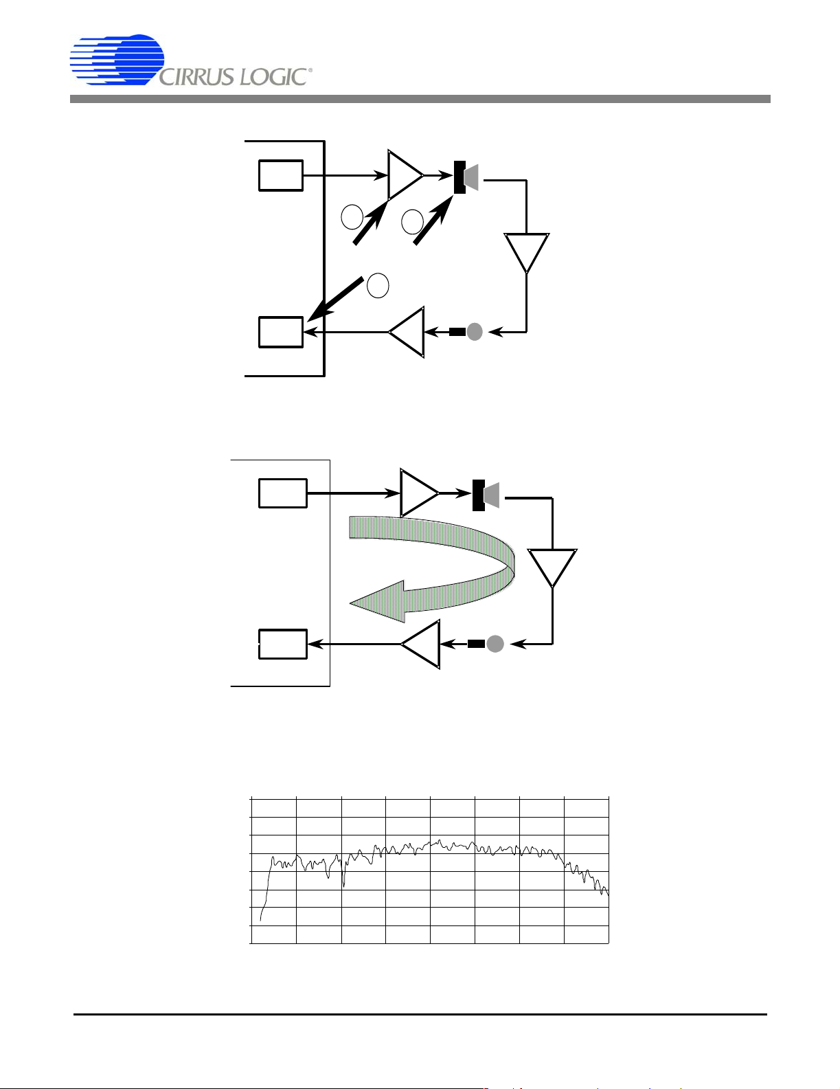
1.3.4 Acoustic Coupling
Figure 5 shows the three most common places for
distortion to be introduced into the acoustic path.
These are the speaker driver, the speaker, and
clipping at the A/D converter after the mic preamp.
With careful choice of the speaker and speaker
driver gain, we can eliminate the first two by using
the techniques previously discussed. The third
distortion source, clipping at the A/D converter, is
controlled by limiting the amount of acoustic
coupling.
The acoustic coupling is defined as the gain (or
loss) between the AO pin and the APO pin on the
CS6422, with TGain set to 0 dB. If TGain is set to
a non-zero value, then the TGain value is added to
the AO/APO gain number to compute the amount
of acoustic coupling.
The acoustic coupling is determined by 5 factors:
the speaker driver gain, the speaker efficiency, the
air coupling between the speaker and the
microphone, the microphone sensitivity, and the
mic preamp gain. Assuming the speaker and mic
have been chosen, the remaining design variables
are the speaker driver gain, the mic preamp gain,
and the speaker and mic position.
Usually, the speaker driver gain is chosen based on
the linearity requirements previously described.
The speaker and mic placement are determined by
ergonomic factors and the desired acoustic path
stability described above. The remaining variable
is the mic preamp gain, which is typically set such
that the worst-case acoustic coupling is between
-9 dB and -15 dB, the first number being the
preferred design target, as shown in Figure 6.
The acoustic path response is highly frequency
dependent. The contributions of the speaker driver
and the mic preamp to the frequency response are
essentially negligible since both of these amplifiers
typically have a stable and well-behaved frequency
response. The dominant factors in the frequency
response of the acoustic path are the speaker's
inherent frequency response, the microphone's
inherent frequency response, and the frequency
response of the path between the speaker and the
mic which is strongly affected by the speaker's
housing. The flatter the frequency response, the
better the echo cancellation.
Figure 7 shows an example acoustic path frequency
response for a speaker and microphone separated
by approximately one meter.
The signal at APO will visibly clip for signals
greater than +5 dBV (5 Vpp). Keep in mind that the
acoustic A/D converter clips at 0 dBV (2.8 Vpp)
when TGain is set to 0 dB.
1.3.5 Setting the Mic Preamp Gain
As stated above, the design goal is to have the
worst-case value for the acoustic coupling, the
highest value across the frequency band of interest,
less than or equal to -9 dB. Strictly speaking, it
need only be less than 0 dB to avoid clipping at the
acoustic A/D converter. The additional 9 dB
provides margin for component tolerance variation
(dominated by speaker variation), component
installation (dominated by speaker/mic placement),
and acoustic path variation (dominated by the
position of the driver, passengers, and objects in the
car). The mic preamp gain is adjusted to achieve
the desired level of acoustic coupling.
There are two methods that can be used to set the
acoustic coupling: the frequency response method
and the loop gain method. The frequency response
method is good because it provides frequency
response information that can be used to increase
the quality of the system (flat frequency response is
desired). The loop gain method is quick, easy, and
requires no additional test hardware beyond the
ability to configure the CS6422's registers.
In the frequency response method, the acoustic
path frequency response, the gain between the AO
and the APO pins on the CS6422, is measured by
automated test equipment and plotted. The
8 AN168REV2
Page 9
AN168
Speaker Driver
Speaker
AO
DAC
1
2
Air
CS6422
Coupling
3
APO
ADC
Mic Preamp
Microphone
Figure 5. Three Common Sources of Acoustic Path Distortion
Speaker Driver
AO
DAC
Speaker
CS6422
ADC
Acoustic Path = -9dB
APO
Mic Preamp
Microphone
Figure 6. Acoustic Coupling Design Target
Acoustic Coupling (dB)
0 500 1000 1500 2000 2500 3000 3500 4000
0
-10
-20
-30
-40
-50
-60
-70
-80
Frequency (Hz)
Air
Coupling
Figure 7. Example Acoustic Coupling Frequency Response
AN168REV2 9
Page 10
AN168
maximum value of this curve is then noted, and
gain is added or subtracted at the mic preamp in
order to set this maximum value to -9 dBV (with
TGain set to 0 dB). This procedure is further
described in the Tests section of this note.
The loop gain method uses howling to determine
the optimum mic preamp gain. In short, the phone
network is disconnected from the CS6422, and
TVol, RVol and NSdt are used to create a +9 dB
path between APO and AO inside the CS6422. The
system will howl, go into regenerative feedback, at
the point that the total loop gain reaches a factor of
'1', or 0 dB. This happens whenever the gain
between AO and APO outside the CS6422 reaches
-9 dB. The frequency of the howl is the frequency
of the maximum loop gain, which is dominated by
the speaker, microphone, and the air path between
the two. Figure 8 illustrates.
The loop gain procedure is as follows:
1) Configure the CS6422 with its default configuration, with the exception of the following:
a) Mic = ‘1’ or ‘0’, depending on whether the
internal mic preamp is used or not
b) TSD = RSD = HDD = ‘1’, transmit and re-
ceive suppressors and half-duplex mode are
disabled
c) ACC = NCC = 'cleared', echo cancelers are
forced to a cleared state to prevent updates
d) AECD = NECD = ‘1’, echo cancelers are
disabled
e) TVol = +12 dB
f) NSdt = -12 dB
g) RVol = +9 dB
2) Adjust the mic preamp gain (or the speaker
driver gain) until the system is just on the verge
of howling. At this point the gain between AO
and APO will be the desired -9 dB.
Disconnect
Network
CS6422
-12dB
NSdt - Network
Sidetone
+9dB
RVol - Receive
Volume
TVol - Transmit
Volume
12dB
Figure 8. Setting the Acoustic Coupling
Goal is -
9dB
A
O
APO
0dB
Speaker
Driver
Adjust
?dB
Mic
Preamp
Air Coupling
-?dB
10 AN168REV2
Page 11

AN168
The register settings to accomplish the above are as
follows:
reg 0: 47a0 (or c7a0 if internal mic preamp is
used)
reg 1: 26a2
reg 2: 0004 (default)
reg 3: 0006 (default)
reg 4: 0008 (default)
reg 5: 033a
Note: If the mic preamp gain is not easily
adjustable in the test circuit, coarse amounts of gain
can be added by using the TGain control, which can
be set to 0 dB, +6 dB, +9.5 dB, or +12 dB.
1.3.6 Acoustic Sidetone
When the coupling path between the speaker and
the microphone is relatively consistent, linear, and
has a high signal-to-noise ratio (SNR), the CS6422
provides good echo cancellation and makes good
training decisions. In the car environment, the SNR
of the acoustic path can be degraded significantly
by road and engine noise and the separation
between the speaker and the mic. In these systems,
it is often useful to introduce a strong, linear,
predictable coupling path electrically by using an
acoustic sidetone.
The acoustic sidetone provides 3 main benefits:
1) The presence of a strong path decreases convergence time, meaning it decreases the time the
CS6422 spends in half-duplex.
2) The linear path enhances stability in systems in
which the strongest real (air) path is distorted.
Note that even though the echo canceller will
not cancel the nonlinear elements of the acoustic echo, it will make better decisions regarding
when to engage the supplementary suppression
algorithms to mask such echo. This results in
improved performance during far-end single-talk.
3) The consistent path provides an echo path that
is independent of the acoustic environment,
making the system less sensitive to path changes and noise. This enhances full-duplex performance by reducing the tendency of the CS6422
to drop to half-duplex when the driver moves.
The amount of sidetone required depends on
several factors. Typically, a good number is
between -24 dB and -12 dB. To be useful, the
electrical coupling should be about as strong as the
strongest typical air coupling, but not much
stronger. A good starting point for systems whose
peak acoustic coupling is -9 dB is -18 dB of
acoustic sidetone. The acoustic sidetone can be
implemented in CS6422 systems by using the ASdt
control, which is configurable to none, -24 dB,
-18 dB, or -12 dB.
1.4 Echo Canceler Parameter
Optimization
One of the benefits of the CS6422 is its high degree
of configurability. Whereas the number of
parameters may seem daunting at first, there are
only a few that need to be tweaked to optimize
performance. The rest can be set once and left
alone.
1.4.1 Starting Example
The following is an example register configuration
that is useful as a starting point for cellular car
hands-free systems.
Note: Actual performance testing should be
performed in a car, not a lab. This is because the car
and the lab present different acoustic environments
to the echo canceler, and the goal is to optimize the
parameters for the target environment, which
requires testing in that target environment.
The following parameter set assumes that there is
no coupling on the network interface to the phone.
If there is a network coupling path, see the Network
Sidetone and Loop Gain sections below.
AN168REV2 11
Page 12

AN168
Configure the CS6422 from reset with the
following:
1) Mic set to '1' or '0', depending on whether the
internal mic preamp is used or not
2) GB = 0.75 dB/ms
3) RVol = +18 dB (this is the default setting; RVol
should be set between +6 dB and +30 dB)
4) Taps = 55.5 ms
5) TVol = 0 dB (this is the default setting; close to
0 dB is better; TVol should be between 0 dB
and +12 dB)
6) NseRmp = 12 dB/s
7) HDly = 150 ms
8) IdlTx = enabled
9) TSAtt = 24 dB
10)PCSen = low
11)TSThd = 12 dB
12)TSBias = 18 dB (default setting)
13)AErle = 18 dB
14)AFNse = -42 dB
15)TGain = 0 dB (can be 0 dB, +6 dB, +9.5 dB, or
+12 dB, depending on mic preamp requirements)
16)NECD = ‘1’ (should be '0' if a network sidetone
is present)
17)ASdt = -18 dB
The register configuration which implements the
above is:
1.4.2 Tweaking the Parameters
1) TGain can be set to 0 dB, +6 dB, +9.5 dB, or
+12 dB, to add gain to the mic preamp if needed based on acoustic coupling tests.
2) RVol can be adjusted down or up based on desired signal level. The value should be kept between +6 dB and +30 dB.
3) TVol can be adjusted to a value between 0 dB
and +12 dB to add gain to the transmit path,
particularly if the mic preamp gain was reduced
to satisfy acoustic coupling requirements.
4) TSThd controls the ERLE level at which the
transmit suppressor engages during far-end single-talk (when the far-end is talking while the
near-end listener is silent). This parameter is
tested using the Far-End Single-Talk Counting
Test described in the Tests section.
5) TSBias controls the ERLE level at which the
transmit suppressor disengages during double-talk. Lower values make it easier to disengage the transmit suppressor, preventing the
undesirable attenuation of near-end speech.
This parameter is tested using the Double-talk
test described in the Tests section.
6) AErle and AFNse control the behavior of the
transition between half-duplex and full-duplex.
Specifically, they influence the time it takes for
the CS6422 to transition between half-duplex
and full-duplex. Lower values of AErle tend to
decrease the transition time. This parameter is
tested using the Full-duplex Transition test described in the Tests section.
reg 0: 1400 (9400 if internal mic preamp is
used)
reg 1: 0a22
reg 2: 0a14
reg 3: a046
reg 4: 5008
reg 5: 018a
12 AN168REV2
7) TSAtt controls the amount of attenuation added
to the transmit path when the transmit suppressor engages. This parameter is tested using the
Far-End Single Talk Test described in the Tests
section.
8) IdlTx causes the half-duplex engine to switch to
transmit during an idle period. This parameter
only has an effect during half-duplex operation.
Page 13

AN168
This parameter can be tested using the
Half-Duplex Alternate Counting Test as described in the Tests section.
9) RSD controls the enable/disable of the receive
suppression engine. The receive suppressor is a
noise squelch that provides 24 dB of attenuation to the receive path when the far-end talker
is silent. The receive suppressor operates in
half-duplex and full-duplex modes. When the
far-end talker is silent, the signal sent to the
speaker drops to almost nothing, that is, background noise is not transmitted. If this is undesirable, the receive suppressor can be disabled
by setting RSD to '1', allowing the noise to pass
to the speaker unattenuated.
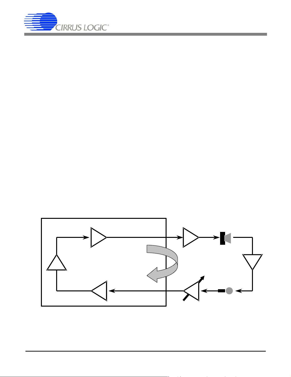
1.4.3 Network Sidetone
Some cellular phones provide a coupling path
between the network transmit and network receive
paths which is used when a full-duplex earpiece
and mic are used. This sidetone path provides an
echo between the mic and the earpiece to let the
user know that the phone is active, similar to the
sidetone supplied by the Central Office in a
standard analog phone handset.
The presence of a network sidetone, here defined as
a coupling path between the NO pin and the NI pin
on the CS6422, increases the complexity of the
system considerably because it forms a closed loop
with the receive path, the acoustic path, and the
transmit path. When a system has a closed loop,
care must be taken to ensure that the loop gain of
the system remains below a factor of '1', or 0 dB, or
howling, regenerative feedback, will result. Figure
9 illustrates.
It is strongly recommended that the network
sidetone on the cellular phone be disabled if
possible. Most cellular phones that provide only an
analog hands-free interface have a means of
disabling the sidetone. Cellular phones that provide
both analog and digital hands-free interfaces
NI
NO
CS6422
RVol
Closed Loop
TVol
AO
Speaker
Driver
Air
Coupling
APO
Mic
Preamp
Cell Phone
Network
Sidetone
AN168REV2 13
NI
Gain
NO Gain
Figure 9. Loop Gain with Network Sidetone
Page 14

AN168
typically employ the sidetone only on the analog
interface, leaving the digital interface
sidetone-free.
If it is not possible to disable the sidetone or work
around it by using a different interface, then the
presence of the sidetone must be considered in the
design of the system. To minimize the loop gain as
well as to prevent the local mic signal from being
echoed out the speaker, it is necessary to enable the
Network Echo Canceler and to allocate Taps to it.
These are the two parameter changes necessary
from the recommendations given above.
Specifically, NECD should be set to '0', and Taps
should be set to either 47.5 ms/16 ms or
39.5 ms/24 ms. Either setting will work;
47.5 ms/16 ms is slightly more desirable since the
network path delay inside the phone is easily
handled by 16 ms of taps, allowing more taps to be
used for modeling the acoustic path.
1.4.4 Loop Gain
The presence of a network sidetone places
constraints on the total loop gain allowed in the
system. The network interface gains are
determined by matching the full scale level of the
phone to the full-scale level of the CS6422. The
speaker driver, acoustic coupling, and mic preamp
gains are determined as described earlier in this
note. The remaining gains are TVol and RVol
inside the CS6422.
Note: TGain is treated as part of the mic preamp
gain, and RGain is treated as part of the network
receive gain.
When the echo cancelers are enabled, they provide
additional loss in the loop that is equal to the ERLE
(Echo Return Loss Enhancement) of each echo
canceler. Because the network path is strong and
stable, the ERLE of the network echo canceler can
be relied upon to reduce the system loop gain.
Because the acoustic path is highly variable, the
ERLE of the acoustic echo canceler should NOT be
relied on to reduce the system loop gain.
The network echo canceler can provide, worst case,
15 dB of additional loss in the loop, provided that
the network path is linear and lossy, that is, the
signal level at NO is reflected back at NI at a lower
amplitude than it originated.
Here's an illustrative loop gain example. Assuming
that the worst-case acoustic coupling is -9 dB and
the network sidetone amplitude, here defined as the
gain between the NO and NI pins on the CS6422, is
-6 dB, and the network ERLE is 15 dB, then
RVol TVol+9615++ 30dB==
maximum. This +30 dB number can be distributed
arbitrarily between RVol and TVol. The placement
of the gain does not affect the stability of the
system. Usually, the gain is distributed to provide a
balance between the transmit path volume and the
receive path volume.
1.5 Tests
In this section, we present some tests which are
useful to identify and solve system-level problems.
These tests should be performed in the listed order.
The first set of tests, Acoustic Coupling, Acoustic
Distortion, and Acoustic ERLE, should be
performed in a lab and in a car. These tests verify
the electrical and the mechanical design of the
system.
The last set of tests, which are actual call test
scenarios, are used to fine-tune the CS6422 register
settings.
NOTE: These tests should be performed in a car.
The latter tests can be performed in a lab, however,
it is likely that the set of optimum coefficients
derived in lab testing will not be optimal for car
use.
14 AN168REV2
Page 15

AN168
1.5.1 Acoustic Coupling
The term ‘Acoustic Coupling’ refers to the gain
between the AO and the APO pins on the CS6422.
It includes the speaker driver gain, the efficiency of
the speaker, the loss in the air path between the
speaker and the microphone, the sensitivity of the
microphone, and the gain of the microphone
preamp.
Here we present two methods of measuring the
acoustic coupling, the loop gain method and the
frequency response measurement method. The
loop gain method is quick, easy, and requires no
additional test equipment to perform, yet provides
only one worst-case coupling number. The
frequency response method is more thorough and
yields more information, but requires automated
test equipment.
1.5.1.1 Loop Gain Method
When a system contains a closed loop whose gain
is greater than 1, howling, or regenerative
feedback, results. See Figure 10.
This howling phenomenon can be used to make a
quick and accurate measurement of the acoustic
coupling between a speaker and a microphone.
In essence, we create a known gain between APO
and AO inside the CS6422 using the TVol, NSdt,
and RVol controls, and increase this gain until
howling results. At the point that howling occurs,
the loop gain of the system is 0dB, or a factor of ‘1’.
In this particular example, we set TVol to +12dB,
NSdt to -12dB, and increase RVol until howling
occurs. The speaker driver gain and mic preamp
gain are known, and the remaining unknown, the
air coupling between the speaker and the mic, is
determined. See Figure 11.
‘a’ dB ‘b’ dB
Loop Gain is the gain of a ‘closed’ loop.
‘f’ dB
When Loop Gain is very slightly greater than 0dB (a factor of ‘1’), howling begins
AN168REV2 15
A closed loop has a path that returns to its starting point.
‘d’ dB‘e’ dB
Loop Gain (dB) = a + b + c + d + e + f
Figure 10. Loop Gain Diagram
‘c’ dB
Page 16

CS6422
Adjust
+?dB
AN168
AO
0dB
RVol - Receive
Volume
Disconnect
Network
Adjust RVol until howling begins; AC = 0 - RVo l - Mic -Spkr
-12dB
NSdt - Network
Sidetone
TVol - Transmit
Volume
Figure 11. Acoustic Coupling Measurement Method
The loop gain measurement procedure is as
follows:
1) Configure the CS6422 with its default configuration, with the exception of the following:
a) Mic = ‘1’ or ‘0’, depending on whether the
internal mic preamp is used or not
b) TSD = RSD = HDD = ‘1’, transmit and re-
ceive suppressors and half-duplex mode are
disabled
c) ACC = NCC = 'cleared', echo cancelers are
forced to a cleared state to prevent updates
d) AECD = NECD = ‘1’, echo cancelers are
disabled
Speaker
Driver
Air Coupling
APO
30dB12dB
Mic
Preamp
-?dB
The register settings to accomplish the above are as
follows:
reg 0: 4xa0 (or cxa0 if internal mic preamp is
used); “x” is the value of RVol
reg 1: 26a2
reg 2: 0004 (default)
reg 3: 0006 (default)
reg 4: 0008 (default)
reg 5: 033a
RVol contains a 4-bit value that results in a gain
given by the following equation:
e) TVol = +12 dB
Gain dB() 30dB RVol 3dB×()–=
f) NSdt = -12 dB
g) RVol = 0 dB
2) Adjust RVol until the system is just on the
verge of howling. At this point the loop gain is
0 dB, and the loss between AO and APO (outside the CS6422) is equal to the RVol value.
16 AN168REV2
For example, if the RVol value required to make
the system howl is ‘5’, then the loss between AO
and APO is (30 - 5 * 3 = 15 dB)
Physical law ensures that the system will howl at
the frequency of maximum coupling. Furthermore,
Page 17

AN168
the frequency of the howl itself is the frequency at
which the loop gain, whose frequency response is
dominated by the acoustic coupling, is maximum.
1.5.1.2 Frequency Response Method
Measuring the frequency response of the acoustic
path in the target environment is strongly
recommended. In general, the flatter the frequency
response, the better the performance of the echo
canceler.
In this method, an automated piece of test
equipment that contains a variable-frequency sine
wave generator coupled with an RMS
measurement device, such as an Audio Precision
System One or System Two, or a Rohde and
Schwarz UPL or UPD is used. Automated
equipment is recommended over a manual sine
wave generator due to the number of frequency
points required (100 or more) and the difficulty of
measuring the mic signal due to constructive and
destructive interference.
The measurement device’s generator can be
connected to the input of the speaker driver or to
the NI pin of the CS6422 through a DC-blocking
capacitor. If connected to the NI pin, RGain and
RVol should each be set to 0 dB, RSD and HDD
should be set to ‘1’, and NCC should be set to
‘cleared’. If connected to the speaker driver input,
the connection between the AO pin and the speaker
driver should be broken.
The sine wave generator should be configured to
output a 1 Vrms (0 dBV) sine wave that sweeps
between 100 Hz and 4 kHz, log distribution is
preferred over linear, and samples at least 100
points, preferably 200 or more for this range.
The return signal can be monitored either at the
APO pin or the NO pin of the CS6422. If monitored
at the NO pin, TSD should be set to ‘1’, and ACC
should be set to ‘cleared’. In either case, the Mic bit
should be set to ‘1’ if the internal mic preamp is
used, or ‘0’ if the internal mic preamp is not being
used.
An example acoustic coupling plot is shown in
Figure 12.
1.5.2 Acoustic Distortion
Earlier in this note, we described a process by
which we could limit the distortion in the acoustic
path by designing the electrical system carefully. It
is still necessary to test the distortion to verify that
the distortion level is below 2% THD.
Acoustic Coupling (dB)
0 500 1000 1500 2000 2500 3000 3500 4000
0
-10
-20
-30
-40
-50
-60
-70
-80
Frequency (Hz)
Figure 12. Example Acoustic Coupling Frequency Response
AN168REV2 17
Page 18

AN168
There are two tests which should be performed, a
Frequency Sweep distortion test and a Buzz test.
1.5.2.1 Frequency Sweep Test
In this test, a piece of automated test equipment
sweeps a sinewave between 100 Hz and 4 kHz,
similar to the Frequency Response Method of
testing acoustic coupling. In this test, the input to
the analyzer is analyzed for relative THD+N by
filtering with a high-Q notch filter at the
fundamental frequency of the input. Additionally, a
C-message filter or a high-order (5 poles or more)
4 kHz low-pass filter should be applied to keep
out-of-band noise from corrupting the
measurement.
The resulting curve shows relative THD+N vs.
Frequency. An example is shown in Figure 13.
This curve, although useful, is not complete
because it lacks information about the coupling
strength at each frequency. A relative THD+N
reading can be degraded by an increase in the
distortion component or a decrease in SNR (which
can be caused by a decrease in signal level or an
increase in noise level). The residual echo level is
dependent only on the amount of distortion. An
SNR degradation due to a decrease in signal level
means that there is no echo at those frequencies to
cancel.
The graph that we need is a relative THD+N curve
that is weighted with the acoustic coupling
information. This curve can be constructed by
normalizing the acoustic coupling curve by shifting
it vertically such that the maximum value is set at
0 dB then adding this normalized curve to the
relative THD+N curve. An example is shown in
Figure 14. Keep in mind that the goal is to have this
weighted distortion curve below 2% THD, or
-34 dB at all points.
These curves were constructed by saving the data
in text format to a file, then importing the
information into a spreadsheet for normalization
and addition.
1.5.2.2 Buzz Test
The distortion measurement method above is
designed to detect harmonic distortion resulting
from clipping at the speaker driver, the speaker, or
the mic preamp. This method is not good at
measuring non-harmonic distortion that results
when the speaker induces mechanical vibrations in
its housing. We refer to these induced vibrations as
‘buzzing’.
Relative THD+N (dB)
0 500 1000 1500 2000 2500 3000 3500 4000
0
-10
-20
-30
-40
-50
-60
Frequency (Hz)
Figure 13. Relative THD+N
18 AN168REV2
Page 19

Coupling-Weighted THD (%)
1.2
1
0.8
0.6
0.4
0.2
0
0 500 1000 1500 2000 2500 3000 3500 4000
Frequency (Hz)
Figure 14. Coupling-Weighted THD+N
AN168
Similar to harmonic distortion, these ‘buzzing’
artifacts cause elevated levels of residual echo
because they result from a non-linear phenomenon
that the echo canceler cannot model.
The test for buzzing is similar to the frequency
sweep distortion test. A full-scale sine-wave is
injected into the speaker-driver input (or the NI
input on the CS6422), and swept slowly between
100 Hz and 4 kHz. This sweep can be performed
manually. As the frequency is swept, listen for the
induced buzzing vibrations. Try placing your hand
on the speaker housing to test for mechanical
vibrations as well. When a buzz is detected, try to
isolate the mechanical cause of the induced
vibration and fix it. Typical solutions involve
inserting spongy foam gaskets between connecting
pieces of plastic or inserting spongy foam between
the speaker’s mounting rim and the housing.
1.5.3 Acoustic ERLE
In order to tell if the system is properly designed, it
is useful to measure the ERLE (Echo Return Loss
Enhancement) that the echo canceler is able to
provide. We present two methods to test ERLE, the
White Noise RMS method and the Loop Gain
method.
The White Noise RMS method measures the
difference in the spectral power level of the signal
with the echo canceler present in the acoustic path
and removed. The Loop Gain method measures the
worst-case ERLE that the echo canceler is able to
achieve by measuring the difference in loop gain
with the echo canceler present in the loop versus
absent.
Both tests are useful. The White Noise RMS
method requires a white noise source and a
band-limited RMS voltage measurement
instrument. The Loop Gain method requires no
additional hardware beyond the ability to configure
the CS6422.
1.5.3.1 White Noise RMS Method
In this test, the CS6422 in configured such that the
transmit and receive suppressors and half-duplex
are disabled. A 2.8 Vpp white noise signal is
injected at NI, and the band-limited (preferably
C-message) RMS voltage is measured at NO with
the echo canceler enabled (ACC = ‘normal’) and
disabled (ACC = ‘cleared).
The test procedure is as follows:
1) Set up the speaker and microphone and adjust
the acoustic coupling to -9 dB by the methods
AN168REV2 19
Page 20

AN168
discussed earlier in this note.
2) Configure the CS6422 from reset with the exception of the following:
a) Mic set to '1' or '0', depending on whether
the internal mic preamp is used or not
b) HDD = ‘1’
c) GB = 0.75 dB/ms
d) TSD = ‘1’
e) ACC = ‘Cleared’
f) Taps = 55.5 ms
g) RSD = ‘1’
h) NseRmp = 12 dB/s
i) PCSen = ‘low’
j) AErle = 18 dB
k) AFNse = -42 dB
l) NECD = ‘1’
m) ASdt = -18 dB
The register configuration which implements the
above is:
reg 0: 5480 (d480 if internal mic preamp is
used)
reg 1: 0a82
reg 2: 0804
reg 3: 2006
reg 4: 5008
reg 5: 018a
3) Inject 2.8 Vpp white noise into NI (capacitively
coupled), and measure the RMS signal level at
NO. The measured signal should be band-limited with either a C-message filter or at least a
5-pole low-pass filter with a corner frequency
of 4 kHz in order to remove out-of-band noise.
4) Record the band-limited RMS voltage level at
NO.
5) Turn OFF the white noise source.
6) Set ACC to ‘Normal’.
7) Turn ON the white noise source.
8) Record the band-limited RMS voltage level at
NO after 5 seconds or more of white noise.
The ERLE is the difference in dB voltage levels of
(8) and (4):
ERLE 20 meas 8()()log× 20 meas 4()()log×–=
The signal at NO can be monitored through
headphones to actually hear the echo canceler train
to the acoustic path.
If the above tests are to be repeated, it is important
to set ACC = ‘cleared’ and to turn off the white
noise source between each test, otherwise results
may be inconsistent.
Typical values obtained using the above technique
range between -9 dB and -30 dB. In general, the
closer together the speaker and mic are and,
consequently, the lower the speaker driver gain, the
better the performance.
1.5.3.2 Loop Gain Method
The loop gain method allows the worst-case ERLE
to be determined without the use of a white noise
source or an RMS voltage meter. In this method,
the adaptive filter is trained on the acoustic path
using speech or white noise, its coefficients are
then frozen, and a closed loop is formed between
TVol, NSdt, RVol, and the acoustic path, which
includes the echo canceler. As in the acoustic
coupling loop gain test, the receive volume is
incremented until howling occurs, and this number
is recorded.
The echo canceler coefficients are then cleared,
effectively removing the EC from the path, and the
receive volume is adjusted again until the point at
which howling occurs. This new value is recorded.
20 AN168REV2
Page 21

AN168
The difference between the two RVol values is the
worst-case ERLE of the echo canceler. Here is the
detailed procedure:
1) Set up the speaker and microphone and mic
preamp gain for -9 dB of acoustic coupling.
2) Configure the CS6422 from reset with the exception of the following:
a) Mic set to '1' or '0', depending on whether
the internal mic preamp is used or not
b) HDD = ‘1’
c) GB = 0.75 dB/ms
d) TSD = ‘1’
e) ACC = ‘Cleared’
f) Taps = 55.5 ms
g) RSD = ‘1’
h) NseRmp = 12 dB/s
i) PCSen = ‘low’
j) AErle = 18 dB
k) AFNse = -42 dB
l) NECD = ‘1’
m) ASdt = -18 dB
The register configuration which implements the
above is:
reg 0: 5480 (d480 if internal mic preamp is
used)
reg 1: 0a82
reg 2: 0804
reg 3: 2006
reg 4: 5008
reg 5: 018a
3) Set ACC to ‘Normal’.
4) Inject speech or 2.8 Vpp white noise into NI for
5 to 10 seconds. This trains the AEC to the
acoustic path. See Figure 15.
5) Set ACC to ‘Freeze’. Try to minimize the
movement in the acoustic path from here on, as
path changes will adversely affect the ERLE re-
CS6422
NI
TVol - Transmit
+0dB
Volume
RVol - Receive
Volume
AEC
‘normal’
-
Mute
+
Mute TVol and train the AEC using speech...
Figure 15. Acoustic ERLE Measurement -- Train the AEC
AN168REV2 21
AO
0dB
Speaker
Driver
-?dB
Air Coupling
APO
30dB
Mic
Preamp
Page 22

AN168
sults.
6) Disconnect the signal source from NI (or simply turn it off).
7) Close the loop by setting NSdt to ‘-12dB’,
RVol to ‘0 dB’, and TVol to ‘+12 dB’.
8) Increase (or decrease) RVol until the system
CS6422
Adjust
+0dB
RVol - Receive
Volume
NSdt - Network
-12dB
Increase RVol until howling begins…record RVol value
Sidetone
TVol - Transmit
Volume
12dB
AEC
‘freeze’
just starts howling. Record this value. See Figure 16.
9) Set ACC to ‘cleared’.
10)Decrease RVol until the system just stops
howling. Record this value. See Figure 17.
11)The worst-case ERLE is the difference between
AO
0dB
Speaker
Driver
Air Coupling
-?dB
-
APO
30dB
+
Mic
Preamp
Figure 16. Acoustic ERLE Measurement -- Freeze AEC
CS6422
Adjust
AO
+0dB
RVol - Receive
Volume
AEC
‘cleared’
-
-12dB
NSdt - Network
Sidetone
TVol - Transmit
Volume
12dB
+
Clear AEC and decrease RVol until howling stops…the difference in RVol is AERLE
0dB
Speaker
Driver
APO
30dB
Mic
Preamp
Figure 17. Acoustic ERLE Measurement -- Clear AEC
Air Coupling
-?dB
22 AN168REV2
Page 23

AN168
the two RVol values in dB.
1.5.4 Call Testing and Coefficient Optimization
The following tests are useful for optimizing the
CS6422 register settings. These tests should be
performed in a car, not a lab. They can be
performed in a lab, but the resulting coefficients
and settings will not be optimal for actual car use.
First, a note on safety. One of the compelling forces
driving the use of hands-free kits in cars is added
safety. Many governments have realized the
dangers inherent when people drive and talk on the
phone at the same time and have mandated the use
of hands-free accessories when cell phones are
used in cars. The studies do not mention the
dangers involved in driving while fine-tuning
hands-free system parameters.
Please, be careful.
on changes in path. In this test, the CS6422 is
loaded with the starting register configuration set
listed earlier in this note, which is repeated here for
convenience:
Configure the CS6422 from reset with the
following:
1) Mic set to '1' or '0', depending on whether the
internal mic preamp is used or not
2) GB = 0.75 dB/ms
3) RVol = +18 dB (this is the default setting; RVol
should be set between +6 dB and +30 dB)
4) Taps = 55.5 ms
5) TVol = 0 dB (this is the default setting; close to
0 dB is better; TVol should be between 0 dB
and +12 dB)
6) NseRmp = 12 dB/s
7) HDly = 150 ms
Optimal car testing requires a minimum of three
people: a driver, a passenger, and a far-end talker.
The driver’s responsibility is solely to drive the car
and to avoid accidents. The passenger and the
far-end talker perform the call testing and
parameter optimization.
Once the test hardware is installed in the car, set the
Acoustic Coupling to a value of -9 dB using the
techniques discussed earlier in this note. Then
begin testing.
1.5.4.1 Far-end single-talk counting
The first test is the Far-End Single-Talk Counting
test. In this test, the far-end talker speaks, usually
incremental counting, and the near-end talker
remains silent.
This test has several sub-tests which are used to
configure specific parameters.
1.5.4.1.1 Subtest A, EC Convergence Test
The EC Convergence Test allows the far-end
listener to hear the echo canceler train, and retrain
8) IdlTx = enabled
9) TSAtt = 24 dB
10)PCSen = low
11)TSThd = 12 dB
12)TSBias = 18 dB (default setting)
13)AErle = 18 dB
14)AFNse = -42 dB
15)TGain = 0 dB (can be 0 dB, +6 dB, +9.5 dB, or
+12 dB, depending on mic preamp requirements)
16)NECD = ‘1’ (should be '0' if a network sidetone
is present)
17)ASdt = -18 dB
The register configuration which implements the
above is:
reg 0: 1400 (9400 if internal mic preamp is
used)
reg 1: 0a22
AN168REV2 23
Page 24

AN168
reg 2: 0a14
reg 3: a046
reg 4: 5008
reg 5: 018a
For the EC Convergence Test, we also disable
Half-Duplex mode and the Transmit Suppressor by
setting HDD = TSD = ‘1’.
Start the test by setting ACC to ‘cleared’ and then
back to ‘normal’. This resets the adaptive filter to a
cleared state.
Initiate the call and have the far-end talker begin
counting while listening for his or her echo. The
level of the echo should lessen with each count
until it reaches a point at which it will attenuate no
further. The test is simply to find out if the echo
level drops on successive counts or not. If it doesn’t
attenuate, then there’s a problem in the system,
usually caused by too much distortion in the path.
The test can be repeated by setting ACC to
‘cleared’ and then back to ‘normal’.
1.5.4.1.2 Subtest B, Half-Duplex to Full-Duplex transition time
Subtest B measures the time it takes for the CS6422
to train sufficiently to move from Half-Duplex
mode to Full-Duplex mode.
The CS6422 is loaded with the standard
recommended coefficient set. At the start of the
test, ACC is set to ‘cleared’ then back to ‘normal’.
This resets the adaptive filter to its cleared state and
prepares it to train to the acoustic path.
After ACC has been set to ‘normal’, the far-end
talker begins counting and listening for echo. The
number at which echo first appears indicates the
transition time to full-duplex.
If it is difficult to determine when the echo appears,
the transmit suppressor can be disengaged for this
test by setting TSD to ‘1’. This removes the
supplementary echo suppression.
1.5.4.1.3 Subtest C, Transmit Suppression test
This test verifies that the TSThd parameter is set
correctly, which controls the engagement of the
Transmit Suppressor. If TSThd is set too high, the
suppressor will not engage reliably, and the far-end
listener will hear residual echo during single-talk.
In this test, the CS6422 is loaded with the standard
coefficient set, with TSMde set to ‘1’, Noise Guard
disabled. The far-end talker counts until the device
transitions to full-duplex. Once in full-duplex, the
transmit suppressor is disengaged by setting TSD
to ‘1’. The far-end talker resumes counting. If there
is no noticeable reduction in the echo level, then the
transmit suppressor is not engaging, and the TSThd
value should be reduced.
1.5.4.2 Double-talk
In the Double-talk test, both the far-end talker and
the near-end talker speak simultaneously. In the
Double-talk test, the CS6422 is loaded with the
recommended set of coefficients. The AEC trains
when the far-end talker speaks while the near-end
talker remains silent. Once the far-end talker hears
the system move to full-duplex, Double-talk testing
can begin.
During the testing, we recommend that one end of
the link count numbers while the other end names
letters of the alphabet, days of the week, months of
the year, or any other syllabic progression that is
easy to generate and easy to detect dropped words.
The goals are to detect how “stable” the system is
in full-duplex by seeing how long the double-talk
can persist without the system dropping to
half-duplex and to test the operation of the transmit
suppressor.
The transmit suppressor should disengage when the
near-end talker speaks. If it doesn’t disengage
properly, then the near-end talker’s speech will be
severely attenuated while the far-end is speaking.
If this happens, adjust the TSBias control to a lower
value (15 dB) and test again.
24 AN168REV2
Page 25

AN168
1.5.4.3 Half-duplex alternate counting
The Half-duplex alternate counting test tests the
half-duplex behavior of the system. This test is
useful even if half-duplex mode is disabled,
because the half-duplex engine controls in part the
training of the adaptive filters.
In the Half-duplex alternate counting test, the
CS6422 is loaded with the recommended
configuration set, with the exception that ACC is
set to ‘cleared’, which prevents the echo canceler
from training and keeps the system in half-duplex.
HDD must be set to ‘0’ for this test.
In this test, the talkers alternate counting in
sequence. For example, the far-end says, “one”,
followed by the near-end saying, “two”, followed
by the far-end saying “three”, etc.
Each side listens for the expected count, and looks
for dropped counts. If the near-end environment is
noisy, it make take a few seconds for the
half-duplexor to begin switching properly.
Parameters that can be adjusted for this test are
HDly, THDet, RHDet, and RSThd. HDly controls
the delay between the system switching from
transmit mode to receive mode. RHDet and THDet
control the SNR level at which speech is detected.
Generally, RHDet and THDet should be equal;
however, if one end of the link is consistently cut
off, they may need to be imbalanced in order to
improve performance.
If there is a network sidetone, it is important that
the Network Echo Canceler be enabled during
half-duplex testing, otherwise the transmit path
may be cut off by its own network echo, causing
halted speech.
1.6 Layout Guidelines
This section contains guidelines regarding PCB
layout in CS6422 systems and car kits in particular.
1.6.1 CS6422-specific guidelines
1) All ground pins on the CS6422 should be referenced to AGND (analog ground plane).
Signals should NOT be routed under the CS6422,
with the exception of the crystal oscillator signals
and the MB signal as shown in Fig. 18.
+5V
Analog
Supply
AVDD
AGND
CS6422
DVDD
DGND
Figure 18. Suggested CS6422 Layout
AN168REV2 25
MB
From
Ferrite
Bead
Page 26

AN168
2) Decoupling and loading capacitors should be
placed as close as possible to the pins they decouple (AVDD, AGND, DVDD, DGND, MB,
CLKI, CLKO), with the smaller-valued capacitor closest to the pin.
3) The traces between the MB pin and the decoupling capacitors connected to it should be short,
shielded with ground plane, and located far
from potentially interfering signals.
1.6.2 Car-Kit guidelines
Cellular car kits typically have three power
networks: +12VBATT/BATTGND,
+5VD/DGND, and +5VA/AGND.
Components powered from a particular power
network should have ground connections to the
ground associated with that power network. For
example, the CS6422 should be powered from
+5VA and its ground pins, including power supply
decoupling capacitor grounds and signal grounds,
should tie to AGND.
The one exception to this is that the attenuator
resistor in the resistor divider between AO and the
speaker driver should be tied to the ground of the
speaker driver, typically BATTGND if the speaker
driver is powered from the +12V battery source.
This prevents the speaker driver from amplifying
noise caused by potential differences between
AGND and BATT GND.
Following are listed the power networks and
components associated with each network.
1.6.2.1 +5VA/AGND Components
1) CS6422, AVDD, DVDD, AGND, DGND, decoupling capacitors, crystal loading capacitors,
signal R’s and C’s with the exception of the attenuator resistor in the voltage divider between
AO and the speaker driver input.
2) Op-amps and analog circuitry between the cell
phone and the CS6422’s NO and NI pins.
1.6.2.2 +5VD/DGND Components
1) Microcontroller
2) Additional +5V control logic circuitry
Note: If the CS6422 and the microcontroller are
powered from the same +5V regulator, +5VA
should be derived from the regulator output
(+5VD) through a ferrite bead.
+5 VA
+
R
+
AO
CS6422
AGND
Gain (dB) = 20 log ( )
Figure 19. Speaker Driver Implementation
26 AN168REV2
1
R
2
BATT
GND
10 µF10 µF
R
2
R1 + R
+
BATT
GND
2
+12 V
-
+
BATT
GND
Gain = +40 dB
+
BATT GND
BATT
GND
4
Ω
Speaker
Page 27

AN168
1.6.2.3 +12VBATT/BATTGND Components
1) Cell-phone battery charger circuitry
2) Speaker driver (if powered from +12V source)
Most cellular phones provide two grounds at the
hands-free connector, DGND and AGND. DGND
ties to the phone battery, and should be connected
to BATTGND on the hands-free kit. The cell
phone’s analog interface pins are referenced to the
AGND signal, and this AGND should tie to AGND
on the hands-free kit.
The DGND plane on the hands-free kit should be
connected to AGND plane in exactly one place.
1.7 Quick list of important points:
The following is a list of things to verify in the
system.
1.7.1 Reset and configuration timing
It is vital that the CS6422 receive a cold reset after
power-on.
1) The RST low time should be at least 1 µs.
2) The time between RST rising and DRDY falling should be at least 110 ms. This is commonly overlooked.
3) Furthermore, when writing multiple control
words to the CS6422, the words themselves
cannot be written at a rate faster than one every
125 µs, since this is the rate at which they are
polled by the DSP. That is, the time from
DRDY falling to DRDY falling must be at least
125 µs.
In implementation, it is easiest to ensure this timing
by limiting the STROBE frequency. Setting the
STROBE period to 10µs, for example, makes the
total time for a register write 200µs (16 data bits +
4 extra STROBE pulses = 20 cycles; 20 cycles *
10µs = 200µs).
1.7.2 Distortion
The total distortion present in any signal path that
the echo cancelers are trying to model should be
limited to 2% THD, worst case across the
frequency band of interest.
1.7.3 Speaker/mic placement
The system should be tested in a car, not a lab. The
microphone should be placed near the driver’s
visor or rear-view mirror. The speaker should be
placed on top of the dash, or in some location such
that there is a minimum of movement in the air
space between the speaker and the microphone.
> 1 µs
RST
DRDY
AN168REV2 27
1
2
> 110 ms
3
> 125 µs
Figure 20. CS6422 Reset and Configuration Timing
Page 28

AN168
1.7.4 Acoustic coupling
The maximum acoustic coupling (across
frequency) between the speaker and the
microphone should be limited to -9 dB. This can be
tested and verified by using techniques described
earlier.
1.7.5 Training sequence
The Acoustic Echo Canceler trains only when the
far-end is talking while the near-end is silent. When
the system is in half-duplex mode, the AEC trains
whenever the receive path is active. When the
system is in full-duplex mode, the AEC does not
train during double-talk. It is only when the
near-end is silent while the far-end is talking that
the acoustic adaptive filter trains.
The Network Echo Canceler trains only when the
near-end is talking and the far-end is silent. When
the system is in half-duplex mode, the NEC trains
when the transmit path is active.
28 AN168REV2
Page 29

AN168
2. APPENDIX - EXAMPLE SPEAKER DRIVER CIRCUITS
In the following pages are 5 example speaker driver
circuits. In each case, the maximum gain is listed
that the speaker driver can assume for the
associated power supply voltage and a 4 ohm
speaker. If less gain is needed, R1 can be increased
or R2 can be decreased. As discussed previously,
volume control should be implemented using the
RVol control inside the CS6422. DO NOT allow
the gain of the speaker driver to be changed during
a call.
In each of the circuits, simple bandpass filtering is
implemented by using a single-pole high-pass
corner around 300 Hz and a single-pole low-pass
corner around 4 kHz. In systems that use a
high-quality speaker whose frequency response is
flat above 15 kHz, additional low-pass filtering
may be necessary to reduce the level of D/A noise
from the CS6422.
In these systems, a 3-pole Butterworth filter can be
placed before the speaker driver. An example
3-pole Butterworth filter is shown in Figure 21.
In this filter, the attenuation can be selected by
adjusting the ratio of R2/R1, preferably by
reducing R2.
TDA1519A’s inherent +46 dB of gain.
R2
Gain 200
The high-pass corner frequency near 300 Hz is
given by:
Fhp
The low-pass corner frequency near 4 kHz is given
by:
Flp
--------------------------------------- -
≈
2πC1 R1 R2+()
-------------------------------------- -
≈
2πC2 R1 R2
2.2 Example 2: TDA2003 -- 3 Watts into 4
The schematic for the TDA2003 speaker driver is
shown in Figure 23. The TDA2003, from ST, is
capable of supplying 3 Watts of RMS power into a
4 Ω load with less than 2% THD. The gain required
to achieve 3 Watts is +10.7 dB, which is
implemented with an attenuation stage of -29.3 dB
followed by the TDA2003 gain implemented as
+40 dB.
--------------------
×=
R1 R2+
1
1
||
()
Ω
R2
⎛⎞
R2
Gain
C2
-------------------------------------
=
2π R2()4kHz()
2.1 Example 1: TDA1519A -- 15 Watts into 4
The schematic for the TDA1519A speaker driver is
shown in Figure 22. The TDA1519A, from Philips
Semiconductors, is capable of supplying 15 Watts
of RMS power into a 4 Ω load with less than
2% THD. The gain required to achieve 15 Watts is
+17.8 dB, which is implemented with an
attenuation stage of -28.2 dB followed by the
AN168REV2 29
------ -
=
R1
1
The high-pass corner frequency near 300 Hz is
given by:
Ω
The low-pass corner frequency near 4 kHz is given
by:
Gain
--------------------
⎝⎠
R1 R2+
Fhp
Flp
--------------------------------------- -
≈
2πC1 R1 R2+()
-------------------------------------- -
≈
2πC2 R1 R2
×=
1
1
()
R4
⎛⎞
⎝⎠
||
-
------
+
1
R5
Page 30

C4
4700pF (COG)
C5
0.47uF
U2
Filt_Out
+
-
MC33202
AN168
C2
3300pF (COG)
R2
12.1k
R1
C1
R4
16.2k
R3
16.2k
-
U1
12.1k
0.047uF
+
C3
1200pF (COG)
MC33202
Vbias
+5V
+5V
Gain = R2/R1
Vbias
R5
10K
C7
0.1uF
C8
10uF
+
C1 = 1/[2 * PI * R1 * (300 Hz)]
C2 = 1/[2 * PI * R2 * (4 kHz)]
R6
10K
+
C6
10uF
Figure 21. Example 4 kHz, 3-Pole Butterworth Low-Pass Filter
U3
MC33202
CS6422_A0
30 AN168REV2
Page 31

+14V
+
C4
2200uF
C6
0.1uF
LS1
AN168
4 Ohm SPEAKER
+46dB
-28.2dB
U1
7
8
C3
10uF
R1
301K
C1
1800pF
4
+
-
TDA1519A
1
+
C2
3300pF
R2
12.1K
6
5
2
3
+
-
9
+
C5
100uF
Figure 22. TDA 1519A Schematic
15 Watts into 4 ohms
Gain = +17.8dB
Gain = [R2/(R1+R2)]*[200]
CS6422_A0
AN168REV2 31
Page 32

AN168
+40dB
+14V
+
C5
100uF
C4
0.1uF
+
C8
1000uF
C6
39nF
U1
4
TDA2003
53
+
-
1
2
C9
100nF
R4
221
R3
39.2
LS1
C7
4 Ohm SPEAKER
R6
1ohm
+
R5
470uF
2.21ohm
+
10uF
C3
R1
340K
C2
3300pF
R2
12.1K
Figure 23. TDA 2003 Schematic
-29.3dB
3 Watts into 4 ohms
Gain = +10.7dB
C1
1500pF
CS6422_A0
Gain = [R2/(R1+R2)]*[1+R4/R5]
32 AN168REV2
Page 33

AN168
2.3 Example 3: TDA1905 -- 2.5 Watts into 4
Ω
The schematic for the TDA1905 speaker driver is
shown in Figure 24. The TDA1905, from ST, is
capable of supplying 2.5 Watts of RMS power into
a 4 Ω load with less than 2% THD. The gain
required to achieve 2.5 Watts is +10 dB, which is
implemented with an attenuation stage of -30 dB
followed by the TDA1905 gain implemented as
+40 dB.
Gain
R2
⎛⎞
--------------------
⎝⎠
R1 R2+
×=
R3
⎛⎞
------ -
1
+
⎝⎠
R4
The high-pass corner frequency near 300 Hz is
given by:
Fhp
--------------------------------------- -
≈
2πC1 R1 R2+()
1
The low-pass corner frequency near 4 kHz is given
by:
+40dB
CS6422_A0
-30dB
C1
1500pF
R1
374K
R2
12.1K
2.5 Watts into 4 ohms
Gain = +10dB
Gain = [R2/(R1+R2)]*[1+R3/R4]
C3
10uF
C2
3300pF
+
8
6
2
+
-
9-16
C7
2.2uF
C5
0.1uF
C10
47uF
+
3
U1
1
TDA1905
7
C6
+
10uF
+
+14V
+
C4
100uF
R3
12.1K
R4
121
R5
1ohm
C9
0.22uF
C8
1000uF
+
LS?
4 Ohm SPEAKER
Figure 24. TDA 1905 Schematic
AN168REV2 33
Page 34

AN168
F
2.4 Example 4: LM1877-- 2 Watts into 4 Ω
The schematic for the LM1877 speaker driver is
shown in Figure 25. The LM1877, from National
Semiconductor, is capable of supplying 2 Watts of
RMS power into a 4 Ω load with less than
2% THD. The gain required to achieve 2 Watts is
+9 dB, which is implemented with an attenuation
stage of -17 dB followed by the LM1877 gain
implemented as +26 dB.
R2
⎛⎞
Gain
The high-pass corner frequency near 300 Hz is
given by:
The low-pass corner frequencies near 4 kHz are
given by:
--------------------
⎝⎠
R1 R2+
Fhp
--------------------------------------- -
≈
2πC1 R1 R2+()
-------------------------------------- -
lp
≈
2πC2 R1 R2
×=
1
()
R3
------ -
R5
R6
------ R5
⎛⎞
1
++
⎝⎠
1
||
2.5 Example 5: LM4861-- 1 Watt into 4 Ω
The schematic for the LM4861 speaker driver is
shown in Figure 26. Note that the power supply for
this speaker driver is +5V. The LM4861, from
National Semiconductor, is capable of supplying
1 Watt of RMS power into a 4 Ω load with less than
2% THD. The gain required to achieve 1 Watt is
+6 dB.
R2
⎛⎞
Gain 2
The high-pass corner frequency near 300 Hz is
given by:
Fhp
The low-pass corner frequency near 4 kHz is given
by:
Flp
-------------------------------
=
2π C1()R1()
-------------------------------
=
2π C2()R2()
------ -
×=
⎝⎠
R1
1
1
34 AN168REV2
Page 35

+26dB
+14V
AN168
LS1
4 Ohm SPEAKER
C9
3-5,10-12
1
+
C5
0.1uF
100uF
R9
C8
R3
0.1uF
12.1K
R6
13.3K
R8
2.7ohm
100uF
C7
+
2
C6
0.1uF
U?
14
LM1187
+
-
6
7
2.7ohm
13
+
-
8
9
-17dB
+
C3
10uF
R1
73.2K
C1
6200pF
CS6422_A0
C2
3900pF
R2
12.1K
R5
R4
1.33K
1M
R7
1M
2 Watts into 4 ohms
Gain = +9dB
Gain = [R2/(R1+R2)]*[1+R3/R5+R6/R5]
Figure 25. LM 1877 Schematic
AN168REV2 35
Page 36

AN168
C2
3300pF
R2
+5V
12.1K
+
C5
100uF
C4
0.1uF
6
R1
LS1
U?
-
4
12.1K
4 Ohm SPEAKER
5
8
LM4861
+
2
3
1
7
C3
10uF
+
1 Watt into 4 ohms
Gain = +6dB
Gain = (2)*(R2/R1)
Figure 26. LM 4861 Schematic
C1
0.047uF
CS6422_A0
3. REVISION HISTORY
Date Revision Change
DEC ‘99 REV1 Original Release
MAR ‘06 REV2 Update company contact information, legal statement.
36 AN168REV2
 Loading...