

Page 1

AN150
Application Note
CS5531/32/33/34 FREQUENTLY ASKED QUESTIONS
INTRODUCTION
The CS5531/32/33/34 are 16 and 24-bit ADCs that
include an ultra low-noise amplifier, a 2 or 4-channel multiplexer, and various conversion and calibration options. This application note is intended to
provide a resource to help users understand how to
best use the features of these ADCs. The “Getting
Started” section outlines the order in which certain
things should be done in software to ensure that the
converter functions correctly. The “Questions and
Answers” section discusses many of the common
questions that arise when using these ADCs for the
first time.
GETTING STARTED
Initialize the ADCs Serial Port
The CS5531/32/33/34 do not have a reset pin. A reset is performed in software by re-synchronizing
the serial port and doing a software reset. Re-synchronizing the serial port ensures that the device is
expecting a valid command. It does not initiate a
reset of the ADC, and all of the register settings of
the device are retained.
A serial port re-synchronization is performed by
sending 15 (or more) bytes of 0xFF (hexadecimal)
to the converter, followed by a single byte of 0xFE.
Note that anytime a command or any other information is to be sent to or read from the ADC’s serial port, the CS pin must be low.
A software reset is performed by writing a “1” to
the RS bit (Bit 29) in the Configuration Register.
When a reset is complete, the RV bit (Bit 28) in the
Configuration Register will be set to a “1” by the
ADC. Any other bits in the Configuration Register
that need to be changed must be done with a separate write to the register after the software reset is
performed.
Set Up the Configuration Register
After a software reset has been performed, the Configuration Register can be written to configure the
general operation parameters of the device. This
step can be omitted if the system is using the default register value. Particular attention must be
paid to the setting of the VRS bit (Bit 25). The VRS
bit should be set to “1” if the voltage on the VREF+
and VREF- pins is 2.5 V or less. If the voltage on
the VREF+ and VREF- pins is greater than 2.5V,
the VRS bit should be set to “0”.
Set up the Channel Setup Registers
The Channel Setup Registers determine how the
part should operate when given a conversion or calibration command. If the system is using the device
with its default settings, the Channel Setup Registers need not be written. Whether the Channel Setup Registers are written or not, they should be
configured for the desired operation of the device
before performing any calibrations or conversions.
Perform a Software Reset
After re-synchronizing the ADCs serial port, a software reset should be performed on the device. A reset will set all of the internal registers to their
default values, as detailed in the datasheet.
Cirrus Logic, Inc.
Crystal Semiconductor Products Division
P.O. Box 17847, Austin, Texas 78760
(512) 445 7222 FAX: (512) 445 7581
http://www.crystal.com
Calibrate the ADC
The CS5531/32/33/34 can be calibrated using the
on-chip calibration features for more accuracy. The
parts do not need to be calibrated to function, and
in some systems a calibration step may not be nec-
Copyright Cirrus Logic, Inc. 2001
(All Rights Reserved)
AN150REV2
SEP ‘01
1
Page 2

AN150
essary. Any offset or gain errors in the ADC itself
and the front-end analog circuitry will remain if the
device is left uncalibrated.
If the built-in calibration functions of the device are
to be used, the calibrations should be performed before any conversions take place. Calibrations are
performed by sending the appropriate calibration
command to the converter’s serial port, and waiting
until the SDO line falls low, which indicates that
the calibration has completed. New commands
should not be sent to the converter until the calibration cycle is complete. More detail about performing calibrations can be found later in this document
and in the datasheet.
Perform Conversions
Conversions can be performed by sending the appropriate command to the converter, waiting for
SDO to fall, and then clocking the data from the serial port. New commands should not be sent to the
converter during a conversion cycle. The various
conversion modes and options are discussed in
more detail later in this document and in the
datasheet.
QUESTIONS AND ANSWERS
How is the input voltage span of the converter calculated?
The positive full-scale input voltage (VFS) is determined by Equation 1.
V
Equation 1. Full-Scale Input Voltage
VREF+()VREF-()–()
--------------------------------------------------------
FS
GA×()
In Equation 1, (VREF+) - (VREF-) is the difference between the voltage levels on the VREF+ and
VREF- pins of the converter. The variable G in the
equation represents the setting of the programmable-gain instrumentation amplifier (PGIA) inside
the part. The variable A in the equation is dependent on the setting of the VRS bit in the Configuration register (bit 25). When this bit is set to ‘0’, A =
1
-------×=
R
G
2, and when the bit is set to ‘1’, A = 1. RG is the
decimal value of the digital gain register, which is
discussed in a later section. For the purposes of this
section, the value of RG is 1.0.
The input voltage span in unipolar mode will be
from 0 V to the positive full-scale input voltage
computed using Equation 1. In bipolar mode, the
input voltage span is twice as large, since the input
range goes from negative full-scale (-VFS) to positive full-scale (VFS). So for unipolar mode, the input voltage span is VFS, and in bipolar mode, it is 2
* VFS.
Example: Using a 5V voltage reference, with the
VRS bit set to 0 in the 32X bipolar gain range, we
see that (VREF+)-(VREF-) = 5 V, G = 32, and A =
2. Using Equation 1, VFS = (5 V)/(32 * 2) = 78.125
mV. Since we are using bipolar mode, the input
voltage span becomes 2 * VFS = 156.25 mV, or
±78.125 mV.
How are the digital output codes mapped to
the analog input voltage of the converters?
The output codes from the converter are mapped as
either straight binary or two’s complement binary
values, depending on whether the part is in unipolar
or bipolar mode. The part measures voltage on the
analog inputs as the differential between the AIN+
and AIN- pins (AIN+ - AIN-). The smallest amount
of voltage change on the analog inputs which will
cause a change in the output code from the converter is known as an “LSB” (Least Significant Bit),
because it is the LSB of the converter’s output
word that is affected by this voltage change. The
size of one LSB can be calculated with Equation 2.
V
()
LSB
Equation 2. LSB Size
In Equation 2, “V
SPAN
range as determined by the voltage reference,
PGIA setting, and gain register value. “N” is the
SPAN
---------------------=
2N()
” is the full input voltage
2 AN150REV2
Page 3
AN150
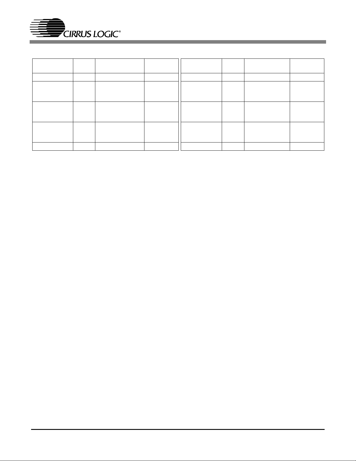
CS5531/33 16-Bit Output Coding CS5532/34 24-Bit Output Coding
Unipolar Input
Voltage
>(VFS-1.5 LSB) FFFF >(VFS-1.5 LSB) 7FFF >(VFS-1.5 LSB) FFFFFF >(VFS-1.5 LSB) 7FFFFF
VFS-1.5 LSB FFFF
VFS/2-0.5 LSB 8000
+0.5 LSB 0001
<(+0.5 LSB) 0000 <(-VFS+0.5 LSB) 8000 <(+0.5 LSB) 000000 <(-VFS+0.5 LSB) 800000
Offset
Binary
------
FFFE
------
7FFF
------
0000
Bipolar Input
Voltage
VFS-1.5 LSB
-0.5 LSB
-VFS+0.5 LSB
Table 1: Output Coding for 16-bit CS5531/33 and 24-bit CS5532/34.
Two's
Complement
7FFF
------
7FFE
0000
------
FFFF
8001
------
8000
Unipolar Input
Voltage
VFS-1.5 LSB FFFFFF
VFS/2-0.5 LSB 800000
+0.5 LSB 000001
Offset
Binary
------
FFFFFE
------
7FFFFF
------
000000
Bipolar Input
VFS-1.5 LSB
-0.5 LSB
-VFS+0.5 LSB
Voltage
Two's
Complement
7FFFFF
------
7FFFFE
000000
------
FFFFFF
800001
------
800000
number of bits in the output word (16 for the
CS5531/33 and 24 for CS5532/34).
Example: Using the CS5532 in the 64X unipolar
range with a 2.5V reference and the gain register
set to 1.0, V
is nominally 39.0625 mV, and N
SPAN
is 24. The size of one LSB is then equal to 39.0625
mV / 2^24, or approximately 2.328 nV.
The output coding for both the 16-bit and 24-bit
parts depends on whether the device is used in unipolar or bipolar mode, as shown in Table 1. In unipolar mode, when the differential input voltage is
zero Volts ±1/2 LSB, the output code from the converter will be zero. When the differential input
voltage exceeds +1/2 LSB, the converter will output binary code values related to the magnitude of
the input voltage (if the differential input voltage is
equal to 434 LSBs, then the output of the converter
will be 434 decimal). When the input voltage is
within 1/2 LSB of the maximum input level, the
codes from the converter will max out at all 1’s
(hexadecimal FFFF for the CS5531/33 and hexadecimal FFFFFF for the CS5532/34). If the differential input voltage is negative (AIN+ is less than
AIN-), then the output code from the converter will
be equal to zero, and the overflow flag will be set.
If the differential input voltage exceeds the maximum input level, then the code from the converter
will be equal to all 1’s, and the overflow flag will
be set.
In bipolar mode, half of the available codes are
used for positive inputs, and the other half are used
for negative inputs. The input voltage is represented by a two’s complement number. When the differential input voltage is equal to 0 V ±1/2 LSB, the
output code from the converter will equal zero. As
in unipolar mode, when the differential voltage exceeds +1/2 LSB, the converter will output binary
values related to the magnitude of the voltage input. When the input voltage is within 1/2 LSB of
the maximum input level however, the code from
the converter will be a single 0 followed by all 1’s
(hexadecimal 7FFF for the CS5531/33 and hexadecimal 7FFFFF for the CS5532/34). For negative
differential inputs, the MSB of the output word will
be set to 1. When the differential input voltage is
within 1/2 LSB of the full-scale negative input voltage, the code from the converter will be a single 1
followed by all 0’s (hexadecimal 8000 for the
CS5531/33 and hexadecimal 800000 for the
CS5532/34). As the negative differential voltage
gets closer to zero, the output codes will count upwards until the input voltage is between -1 1/2 and
-1/2 LSB, when the output code will be all 1’s
(hexadecimal FFFF for the CS5531/33 and hexadecimal FFFFFF for the CS5532/34).
To calculate the expected decimal output code that
you would receive from the ADC for a given input
voltage, divide the given input voltage by the size
AN150REV2 3
Page 4

AN150
of one LSB. For a 5 mV input signal when the LSB
size is 4 nV, the expected output code (decimal)
from the converter would be 1,250,000.
What is the relationship of the VREF input
voltage and the VRS bit to the analog inputs
of the converter?
The voltage present on the VREF+ and VREF- inputs have a direct relationship to the input voltage
span of the converter. The differential voltage between the VREF inputs ((VREF+) - (VREF-))
scales the span of the analog input proportionally.
If the VREF voltage changes by 5%, the analog input span will also change by 5%. The VREF input
voltage does not limit the absolute magnitude of the
voltages on the analog inputs, but only sets the
slope of the transfer function (codes output vs. voltage input) of the converter. The analog input voltages are only limited with respect to the supply
voltages (VA+ and VA-) on the part. See the
“Common-mode + signal on AIN+ or AIN-” discussion in this document for more details on these
limitations.
The VRS bit in the configuration register also has a
direct effect on the analog input span of the converter. When the differential voltage on the VREF
pins is between 1 V and 2.5 V, the VRS bit should
be set to ‘1’. When this voltage is greater than 2.5
V, the VRS bit should be set to ‘0’. When set to ‘0’,
a different capacitor is used to sample the VREF
voltage, and the input span of the converter is
halved. The proper setting of this bit is crucial to
the optimal operation of the converter. If this bit is
set incorrectly, the converter will not meet the data
sheet noise specifications.
The purpose of the VRS bit is to optimize the performance for two different types of systems. In
some systems, a precision 2.5 V reference is used
to get absolute accuracy of voltage measurement.
Other systems use a 5 V source to provide both the
reference voltage and an excitation voltage for a ratiometric bridge sensor. The performance of the
system can be enhanced by selecting the appropriate reference range.
In a system that is performing ratiometric measurements, using a 5 V reference is usually the best option. Ratiometric bridge sensors typically have a
very low output voltage range that scales directly
with the excitation voltage to the sensor. Because
the converter’s input span can be the same with either a 2.5 V reference or a 5 V reference, and the
voltage output from the ratiometric sensor will be
twice as large with a 5 V excitation, the system can
achieve higher signal to noise performance when
the sensor excitation and the voltage reference are
at 5 V.
For systems in which absolute voltage accuracy is
a concern, using a 2.5 V reference has some advantages. There are a wide variety of precision 2.5 V
reference sources available which can be powered
from the same 5 V source as the ADC. However,
most precision 5 V references require more than 5
V on their power supplies, and a second supply
would be needed to provide the operating voltage
to a voltage reference. Since the same input ranges
are available with either reference voltage, a 2.5 V
reference provides a more cost and space-effective
solution. Additionally, for systems where the 1X
gain range is used, a 2.5 V reference voltage gives
the user the option of using the self gain calibration
function of the ADC, where a 5 V reference does
not.
What are the noise contributions from the
amplifier and the modulator?
The amplifier used in the 2X-64X gain ranges of
the part has typical input-referred noise of 6
nV/√Hz for the -BS versions, and 12 nV/√Hz for
the -AS versions. The modulator has typical noise
of 70 nV/√Hz for the -BS versions, and 110
nV/√Hz for the -AS versions at word rates of 120
samples/s and less. At word rates higher than 120
samples/s, the modulator noise begins to rise, and
is difficult to model with an equation. The
4 AN150REV2
Page 5

AN150
CS5531/32/33/34 datasheet lists the typical RMS
noise values for all combinations of gain range and
word rate.
In the 32X and 64X gain ranges, the amplifier noise
dominates, and the modulator noise is not very significant. As the gain setting decreases, the amplifier noise becomes less significant, and the
modulator becomes the dominant noise source in
the 1X and 2X gain ranges. The noise density from
the amplifier and the modulator for word rates of
120 samples/s and lower can be calculated using
Equation 3.
Noise Density
Equation 3. Noise Density
NAG×()2NM()
----------------------------------------------------=
G
2
+
In Equation 3, G refers to the gain setting of the
PGIA. NA refers to the amplifier noise, and NM refers to the modulator noise. By using the noise
numbers at the beginning of this section, a noise
density number can be found for any gain range
setting. The typical RMS noise for a given word
rate can be estimated by multiplying the noise density at the desired gain range by the square root of
the filter’s corner frequency for that word rate. This
estimate does not include the noise that is outside
the filter bandwidth, but it can give a rough idea of
what the typical noise would be for those settings.
The true RMS noise number will be slightly higher,
as indicated by the RMS noise tables in the
datasheet.
The apparent noise numbers seen at the output of
the converter will be affected by the setting of the
internal gain register of the part. The typical RMS
noise numbers calculated in this section and shown
in the datasheet’s RMS noise tables correspond to
the noise seen at the converter’s output using a gain
register setting of approximately 1.0.
What factors affect the input current on the
analog inputs?
In the 1X gain range, the inputs are buffered with a
rough-fine charge scheme. With this input structure, the modulator sampling capacitor is charged
in two phases. During the first (rough) phase, the
capacitor is charged to approximately the correct
value using the 1X buffer amplifier, and the necessary current is provided by the buffer output to the
sampling capacitor. During the second (fine) phase,
the capacitor is connected directly to the input, and
the necessary current to charge the capacitor to the
final value comes from the AIN+ and AIN- lines.
The size of the sampling capacitor, the offset voltage of the buffer amplifier, and the frequency at
which the front-end switches are operating can be
multiplied together (CxVxF) to calculate the input
current. The buffer amplifier’s offset voltage and
the modulator sampling capacitor size are a function of the silicon manufacturing process, and cannot be changed. The frequency at which the
switches are operating is determined directly by the
master clock for the part, and is the only variable
that users can modify which will have an effect on
the input current in this mode. The input current
specified in the datasheet assumes a 4.9152 MHz
master clock.
In the 2X-64X gain ranges, the input current is due
to small differences in the silicon that makes up the
chopping switches on the front end of the amplifier.
The difference between these switches produces a
small charge injection current on the analog inputs.
The frequency at which the switches are operating
is derived directly from the master clock of the part,
and the input current will change as the master
clock frequency changes. Higher master clock frequencies will produce higher input currents. Likewise, changes in the VA+ and VA- supply voltages
will change the amount of charge injection that is
produced by the switches, and higher supply voltages will produce more current on the inputs. The
input current specified in the datasheet assumes a
4.9152 MHz master clock and 5 V between the
AN150REV2 5
Page 6

AN150
VA+ and VA- supply pins.
What factors affect the input current on the
voltage reference inputs?
The input structure on the VREF pins is similar to
the input structure for the 1X gain range. The inputs
are buffered with a rough-fine charge scheme.
However, the size of the capacitor (C) in the equation CxVxF changes with the setting of the VRS bit
in the configuration register. With the VRS bit set
to ‘1’, the capacitor size is cut in half, which also
reduces the VREF input current by 1/2. Like the analog input current, the VREF input current will
change with clock frequency, and is specified with
a 4.9152 MHz clock.
How do the offset and gain register settings
affect the input range of the converter?
The offset and gain registers have a direct effect on
the output codes of the converter. Because of their
effects on the output codes from the converter, they
also have an apparent effect on the input voltage
span of the converter.
The contents of the offset registers are 24-bit 2’s
complement numbers (with a trailing byte of 0’s to
extend the register length to 32 bits) that shift the
output codes from the converter up or down by a
certain amount. The value in the offset register for
a given channel times a scaling value of
1.83007966 will be subtracted from every conversion on that channel before it is output from the
converter. Because this shifts the output of the converter, it will also shift the input span up or down,
depending on the contents of the offset register.
The corresponding effect on the input voltage depends on both the input span of the converter, and
the gain register setting. The multiplication factor
of 1.83007966 is compensation for the effects of
the digital filter on this register. The offset register
may be used to remove a large bridge offset, or other offset errors in a system.
0x00000000, the measured output code from the
converter with a given input voltage is 0x000100
(256 decimal). When the offset register is set to
0x00001E00 (30 decimal, after truncating the last
byte), the expected shift in output code from the
converter would be 1.83007966 * 0x00001E =
0x000036 (54 decimal). Subtracting this from the
original output code gives 0x000100 - 0x000036 =
0x0000CA (202 decimal).
The contents of the gain registers are 30-bit fixedpoint numbers which can range from 0 to 64 - 2
when expressed as decimal numbers (with two
leading 0’s to extend the register length to 32 bits).
Although the maximum gain register setting is
nearly 64, gain register settings above 40 should
not be used. The gain register has a scaling effect
on the output codes of the converter. After subtracting the contents of the offset register, every conversion is multiplied by the gain register for that
particular channel. This changes the slope of the
converter, and has an inverse proportional relationship to the input span of the converter, as seen in
Equation 1, where the decimal equivalent of the
gain register is represented with the variable RG.
Example: With a gain register setting of
0x01000000 (1.0 decimal) and a given input voltage, the output code from the converter is
0x009C40 (40,000 decimal). If the gain register is
changed to 0x01C00000 (1.75 decimal), the output
code from the converter becomes 0x009C40 * 1.75
= 0x011170 (70,000 decimal). Thus, the effective
input range has also been scaled by 1/1.75.
Because this multiplication is done after the subtraction of the offset register, the gain register setting has a direct effect on the offset introduced by
the offset register as well. It is for this reason that
any adjustments to the offset register should take
into account the gain register value, as well as the
1.83007966X filter gain factor that will be applied
afterwards.
-24
Example: With an offset register setting of
6 AN150REV2
What is the purpose of the Filter Rate Select
Page 7

AN150
(FRS) bit in the configuration register?
The FRS bit (bit 19 in the Configuration Register)
is used to select between two different sets of output word rates. When running the ADC from a
4.9152 MHz clock, the FRS bit can be toggled with
a simple software switch to provide either 50 Hz or
60 Hz rejection in situations where this is applicable. The default state of the FRS bit is zero. In this
mode, the word rates from the ADC are 7.5, 15, 30,
60, 120, 240, 480, 960, 1920, and 3840 samples/s
(when running from a 4.9152 MHz clock). When
the FRS bit is set to one, these word rates and their
corresponding filter characteristics scale by a factor
of 5/6, producing output word rates of 6.25, 12.5,
25, 50, 100, 200, 400, 800, 1600, and 3200 samples/s. All of the word rates and filter characteristics in the part will also scale with the master clock
frequency. Setting the FRS bit in the configuration
register has the same effect as changing the clock
frequency by a factor of 5/6, without having to
change the hardware on the board.
How are the channel setup registers in the
converters used?
The channel setup registers each hold two 16-bit
“Setups”, which can be thought of as pre-defined
calibration and conversion instructions. These 16bit register spaces contain all of the information
needed by the converter to perform a conversion or
calibration in the desired operating mode. The bit
selections in the Setups allow the user to choose the
physical channel, gain range, polarity, and word
rate to convert with, as well as the desired state of
the two output latch pins. They also define whether
the current source used for detection of an open circuit should be turned on, and if a delay should be
added between the switching of the latch outputs
and the beginning of a conversion cycle. By default, all of these registers are initially set to convert
on channel 1 in the 1X, bipolar input range at an
output word rate of 120 samples/s with the latch
pins both set to ‘0’, the current source off, and no
delay time. These registers must be modified when
the part is to be operated in a mode other than the
default settings. An entire channel setup register
(two Setups) must be read or written all at once,
even if one of the Setups in the register is not being
modified. If a “write all” or “read all” command is
issued on the channel setup registers, all four of the
registers (eight Setups) must be written or read.
When issuing a conversion or calibration command
to the converter, the channel setup register pointer
(CSRP) bits indicate which Setup to follow when
performing the calibration or conversion. The converter will configure itself according to the information found in the indicated Setup, and perform
the desired operation. The Setups allow the user to
select from multiple converter settings without
having to re-configure the converter each time the
configuration (channel, gain setting, word rate,
etc.) needs to change.
How is the delay time (DT) bit in each Setup
used?
The delay time (DT) bit in each Setup register adds
a fixed amount of delay between the new state of
the output latch pins, and the start of a new conversion cycle. This allows the user to control circuitry
on the front-end of the device with slower response
times or power-on times with the output latch bits
of the converter, and start the conversion after the
front-end circuitry has settled. The delay time is
fixed at 1280 master clock cycles (approximately
260 µs when running from a 4.9152 MHz clock)
when the FRS bit in the configuration register is set
to ‘0’. When the FRS bit is set to ‘1’, the delay time
is extended to 1536 clock cycles (approximately
312 µs when running from a 4.9152 MHz clock).
For circuitry that takes longer than this to power on
or switch, a “dummy” conversion at a different
word rate can be used to add some delay time, or
the latch bits can be controlled from the Configuration Register.
AN150REV2 7
Page 8

AN150
What is the difference between a “self” calibration and a “system” calibration?
A self calibration uses voltages that are available to
the converter to perform calibrations, and does not
take into account any system-level effects. The
converter performs a self offset calibration by disconnecting the AIN+ and AIN- inputs of the specified channel, and shorting them to the commonmode internal to the ADC. The converter then does
a conversion and computes a value for the offset
register. A self gain calibration is performed by disconnecting the AIN+ and AIN- inputs and connecting them to the VREF+ and VREF- inputs
respectively. The converter then performs a conversion and calculates the gain register value from
that conversion. Self calibrations are only valid in
the 1X gain range with a voltage reference of 1 to
2.5 V. A self calibration of offset is possible in the
other gain ranges by using the Input Short (IS) bit
in the Configuration Register. This bit can be set to
‘1’, and a system offset calibration can be performed on the appropriate channel. The IS bit must
be set back to ‘0’ for normal operation of the converter.
How accurate is the converter without calibration?
The converter’s gain settings are not factory
trimmed, so if the converter is not calibrated, the
absolute gain accuracy is typically ±1%. The tracking error between the different PGIA gain settings
(2X - 64X) is typically about ±0.3%. If absolute accuracy is required, the converter should be calibrated for both offset and gain in the specific ranges
where it is needed.
What are the advantages of using the on-chip
calibration registers?
The on-chip calibration registers allow the converter to be easily interfaced to a simple, low-cost, 8-bit
microcontroller without a lot of software overhead.
The subtraction operation used by the offset register and the multiplication operation used by the
gain register can both be performed inside the converter for fast, precise results when using even a
very simple microcontroller. The internal registers
also provide the user an easy means to use a variety
of different calibration techniques for more accuracy.
System calibrations rely on the correct voltage levels being applied to the voltage inputs during the
calibration operation. For a system offset calibration, the desired “zero” point should be applied to
the AIN+ and AIN- inputs before the calibration
command is sent and throughout the calibration
process. Typically, this point is zero volts, but the
converters can calibrate out ±100% of the nominal
input range in bipolar mode, and ±90% of the nominal input range in unipolar mode. During a system
gain calibration, the desired full-scale signal should
be applied to the voltage inputs of the converter.
The CS5531/32/33/34 can calibrate the gain slope
with input voltages that are anywhere between 3%
and 110% of the nominal full-scale voltage.
8 AN150REV2
Why is there no offset DAC in these converters?
The high dynamic range of the CS553x family of
ADCs eliminates the need for an offset DAC. The
offset register can perform the same function that
an offset DAC would normally do in other ADCs.
For example, a typical 2 mV/V bridge has a maximum output of 10 mV with a 5 V excitation supply.
Using the 64X gain range in unipolar mode, there
is still approximately 29 mV of headroom that can
accommodate sensor or system offsets. Performing
a system-level calibration or employing gain scaling techniques allow the user to adjust the input
range of the converter to a 0 to 10 mV range after
removing any offset that is present. Using the 7.5
samples/s word rate, the dynamic range of these
converters allows them to still achieve 17 bits of
Page 9

AN150
noise-free resolution (for the -BS versions of the
parts) over this input range, even in the presence of
large offset voltages.
What is “digital gain scaling” and how is it
useful?
The term “digital gain scaling” is used to describe
the way that the gain register in these converters
can be manipulated to digitally scale a smaller input voltage over the entire output code range of the
ADC. Recall that the gain register can be varied
from 0 to 64 - 2
imal. Because the gain register can be manually
written and read, this function may be done within
the system software. In addition, the gain register
provides a very accurate means of changing the input span of the ADC without having to perform a
new calibration. For example, the gain register can
be read from the part, shifted left by 1 bit and written back into the part. This will have the effect of
doubling the converter’s gain without introducing
any gain error, as changing the amplifier gain setting in the part would. Non-binary gain changes
can also be implemented using this type of gain
register manipulation. This allows for virtually any
input voltage span between 5 mV and 2.5 V, using
a combination of amplifier gain settings and gain
register manipulation.
-24
, but should not exceed 40 (dec-
What are some different approaches to using
calibration in my system?
Calibration can be done at the manufacturing and
testing stage, or in the field. A calibration step done
at the manufacturing or testing stage is generally
referred to as a factory calibration, and is normally
performed only once. A field calibration on the other hand, may be done at any time when the system
is in operation, either automatically or initiated by
the user. Some systems may only use one type of
calibration, where other systems may use a combination of both field and factory calibration. The advantage of a factory calibration is that it can usually
be performed with more precise equipment, and
user error is not a problem. Field calibration has advantages also, since it can take into account the actual environment where the system will be
operating, and may be desirable or even necessary
for some systems.
The easiest way to implement a factory calibration
is to write the system software so that it has two operating modes: “calibration mode” and “user
mode”. The normal operation mode when powering on the system should be the user mode. In this
mode, the system should perform all the functions
relative to the end user. The calibration mode can
be entered with a hardware jumper setting, a software switch, or any number of other options, but it
should not be a normal function for the user. In calibration mode, the system can perform any necessary calibration and configuration tasks, and store
the results to some form of on-board, non-volatile
memory. An example of this is to use the on-chip
system calibration functions to perform offset and
gain calibration, and then read the calibration results from the ADC and store them to EEPROM. In
user mode, the system would then read the registers
out of EEPROM and write the values into the
ADC’s registers on power-up to be used for normal
operation.
I need to be able to do a field calibration periodically on a weigh scale using calibration
weights. Are the internal calibration registers
useful for this type of calibration?
The internal calibration registers can be very useful
in this type of calibration, though this may not be
obvious at first. The usual method of calibrating a
scale with calibration weights is to first zero-out the
scale with nothing on the platform, and then adjust
the output of the scale to the correct reading once a
calibration weight has been placed on the platform.
If the on-chip gain register is going to be used to adjust the scale’s output, the zero-point of the scale
should first be calibrated by setting the gain register
AN150REV2 9
Page 10

AN150
to 1.0 and performing a system offset calibration,
or adjusting the offset register until the scale reads
zero. Following this, the gain register can be adjusted to obtain the correct reading for the calibration
weight. One way of doing this is to set the gain register to a value that will give approximately the correct reading from the scale, and perform a
conversion (or multiple conversions) to get a display output from the scale. The gain register can
then be read from the part, and a value can be added
or subtracted based on user input to adjust the gain
register up or down. Once the gain has been adjusted and written back into the ADC, another conversion (or multiple conversions) can be performed to
get a new display output from the scale. This process can be repeated until the display output matches the desired value. In a more complex system,
this process may even be automated such that the
user enters the magnitude of the calibration weight,
and the system adjusts the gain register and takes
readings until the value from the scale reads the
same as the desired calibration value.
How are the OG1-OG0 bits in the Channel
Setup Registers used?
The OG1-OG0 bits in the Channel Setup Registers
allow the system to select from any of the offset
and gain registers available in the device when performing conversions on a specific channel. Normally, the offset and gain registers associated with
the currently selected physical channel (as specified by CS1-CS0 in the Setup) are used when performing conversions. To tell the ADC that the
OG1-OG0 bits are to be used instead, a ‘1’ must be
written to the Configuration Register’s OGS bit (bit
20). Then, the offset and gain registers for the channel specified by the OG1-OG0 bits will be used,
while the conversion is still performed on the channel specified by CS1-CS0. This allows a system to
quickly access different gain and offset register settings for conversions on the same physical channel,
without having to write those registers into the de-
vice every time. When the OGS bit in the Configuration Register is equal to ‘0’, the CS1-CS0 bits in
the Setup are used to select the offset and gain registers that will be accessed.
What is the difference between single and
continuous conversion mode?
The most noticeable differences between these two
modes are the speed at which conversions can be
performed, and whether the converter will begin a
new conversion when the current one is finished. In
continuous conversion mode, every conversion is
output from the ADC, and the converter will continue to perform conversions until it is halted by the
system microcontroller. This includes any un-settled outputs from the sinc3 or sinc5 filter. Data is
converted and output from the part at the output
word rate specified by the selected Setup. Continuous conversion mode is most useful when performing conversions on a single channel for extended
periods of time. The very first output word of a continuous conversion cycle takes longer than subsequent conversions, due to some internal
synchronization of the converter.
The single conversion mode is different in that the
digital filter processes the modulator bitstream until it can compute a fully-settled result to output a
data word. A conversion in single conversion mode
therefore lasts longer than one performed in continuous conversion mode. In addition, when a single
conversion is finished, the part will not perform another conversion until a new conversion command
is initiated. Single conversion mode is most useful
when repeatedly performing conversions on more
than one channel of the part, or when using an external multiplexer.
Note that the time to arrive at a fully-settled output
from the part in continuous conversion mode is the
same amount of time that a single conversion takes.
10 AN150REV2
Page 11

AN150
Why is the “Common mode + signal on AIN+
or AIN-” specification different for the 1X
gain range?
This difference is due to the fact that there are actually two different amplifiers inside the converter. In
the 1X gain range, a rail-to-rail, unity-gain amplifier is used. A rail-to-rail amplifier is necessary in the
1X gain range to permit the large input voltage
swings that are expected with this gain range. To
achieve the high level of performance typical of the
CS553x family in the 2X-64X gain ranges, a chopper-stabilized, low-drift, multi-path amplifier is
used. The architecture of this amplifier does not
permit rail-to-rail input capability. In the 2X-64X
gain ranges, input signals into the AIN+ and AINinputs must remain higher than (VA- + 0.7 V) and
lower than (VA+ - 1.7 V) for accurate measurements to occur.
A further consideration is the output of the amplifier. Figure 1 shows a model of the PGIA. In addition
to the common mode requirements on the analog
inputs, the user must ensure that the output of the
amplifier does not become saturated. Using the
equations for VCM and VIN shown in Figure 1, the
voltages on the output of the amplifier (OUT+ and
OUT-) are equal to VCM ± (G × VIN)/2. The ampli-
AIN+
VA+
VA-
OUT+
(G-1)xR
2xR
fier cannot drive the voltage on the OUT+ or OUTpins below (VA- + 0.1 V) or above (VA+ - 0.1 V).
When either OUT+ or OUT- reaches or goes beyond these limits, the gain will become (2 × G)/(G
+ 1). To prevent this from happening, the front-end
circuitry on the ADC should be designed to ensure
that both OUT+ and OUT- remain within these limits at all times.
How do I use the internal multiplexer in the
part?
The different channels of the internal mux can be
selected using the Setups in the Channel Setup
Registers. The most effective way of using the internal mux is to initiate two or more Setups with
different physical channel values, and then alternate between the Setups as needed while performing single conversions. Single conversion mode is
recommended when using the internal mux if the
user wants to switch between channels as quickly
as possible. No advantage is gained by using the
continuous conversion mode, since the settling
time for this mode is the same as for the single conversion mode, and it takes more software overhead
on the microcontroller’s part to start and stop the
conversions. The single conversion mode will ensure that each new conversion from the different
mux settings will produce a fully-settled result.
Continuous conversion mode can be useful, however, if the user wants to convert a single channel
for long periods of time, and only periodically get
a sample from other channels. Data on a single
channel can be collected much faster using this
mode.
VA+
AIN-
(G-1)xR
OUT-
How is the guard drive output pin used?
The A0 pin on the CS5531/32/33/34 has a dual
VIN = (AIN+) - (AIN-)
VA-
(AIN+) + (AIN-)
VCM =
2
function as both a latch output and an output for the
instrumentation amplifier’s common-mode voltage. The setting of the GB bit (bit 26) in the Configuration Register controls which mode this pin is
Figure 1. Amplifier Model (2X-64X Gain)
AN150REV2 11
in. When the GB bit is ‘0’, the A0 pin functions as
Page 12

AN150
an output latch pin. When the GB bit is set to ‘1’,
the instrumentation amplifier’s common-mode
voltage is output on the A0 pin.
The amplifier’s common-mode voltage is only output on the A0 pin when the 2X-64X instrumentation amplifier is on, and the device is in the normal
operating mode. On power-up, the instrumentation
amplifier is off by default. To engage the amplifier,
a conversion or calibration must be started with the
part set up to use a gain from 2X to 64X. The amplifier will remain on until a conversion or calibration is performed in the 1X gain range. When the
part is in standby or sleep mode, the instrumentation amplifier is powered down.
It is important to note that the guard drive output
typically can only source about 10-20 uA of drive
current. If the guard signal is used in an application
which requires more drive current, an external
buffer should be used to provide the necessary current. Also, the guard drive output should be protected against high voltage or current spikes, if they are
likely to occur. Voltage or current spikes into the
guard buffer can damage the ADC, and cause the
ADC to malfunction.
12 AN150REV2
Page 13

• Notes •
Page 14

 Loading...