

Page 1
WIT2450
2.4GHz Spread Spectrum Wireless Industrial Transceiver
Integration Guide
3079 Premiere Pky Ste 140
Duluth, Georgia 30097
www.cirronet.com
+1 (678) 684-2000
Page 2

Important Regulator y Information
Cirronet Product FCC ID: HSW-2450
IC 4492A-2450
Note: This unit has been tested and f ound to comply with the lim its for a Class A digita l device,
pursuant to part 15 of the FCC Rules. These limits are designed to provide reasonable protection
against harmf ul interfer ence when the equi pment is operated in a com mer cial enviro nment. T his
equipment generates, us es , and can r a dia te r a dio f r equenc y en er g y and, if not installed a nd us ed
in accordance with the instruction manual, may cause harmful interference to radio
communications. Operation of this equipment in a residential area is likely to cause harmful
interference in which case the user will be required to correct the interference at their expense.
FCC s MPE Requirements
Information to user/installer regarding FCC s Maximum Permissible Exposure (MPE) limits.
Notice to users/installers using the 24 dBi parabolic dish antenna in conjunction with all Cirronet
RF products.
FCC rules limit the use of this antenna, when connected to Cirronet RF products for point-to-point
applications only. It is the responsibility of the installer to ensure that the system is prohibited from
being used in point-to-multipoint applications, omni-directional applications, and applications where there
are multiple co-located intentional radiators transmitting the same information
operation using this antenna is forbidden.
Notice to users/installers using the following fixed antennas, with Cirronet RF products:
Andrews 24dBi parabolic dish
Andrews 18dBi parabolic dish
Cushcraft 15dBi Yagi,
Mobile Mark 14dBi Corner Reflector,
Mobile Mark 9dBi Corner Reflector
Notice to users/installers using the following mobile antennas, with Cirronet RF products:
Mobile Mark 12dBi omni-directional,
Mobile Mark 9dBi omni-directional,
MaxRad 5dBi whip,
Cirronet Patch antenna,
Ace 2dBi dipole,
Mobile Mark 2dBi Stub
The field strength radiated by any one of these
antennas, when connected to Cirronet RF
products, may exceed FCC mandated RF
exposure limits. FCC rules require
professional installation of these antennas in
such a way that the general public will not be
closer than 2 m from the radiating aperture of
any of these antennas. End users of these
systems must al so be informed that RF
exposure limits may be exceeded if personnel
come closer than 2 m to the apertures of any of
these antennas.
The field strength radiated by any one of these
antennas, when connected to Cirronet RF
products, may exceed FCC mandated RF
exposure limits. FCC rules require
professional installation of these antennas in
such a way that the general public will not be
closer than 20 cm from the radiating aperture
of any of these antennas. End users of these
systems must al so be informed that RF
exposure limits may be exceeded if personnel
come closer than 20 cm to the apertures of any
of these antennas.
. Any other mode of
Page 3

Declaration of Conformity
Warning! The RLAN transceiver within this device uses a band of frequencies that are not completely harmonized
within the European Community. Before using, please read the European Operation Section of the Products User’s
Guide for limitations.
0889 is the identification number of RADIO FREQUENCY INVESTIGATION LTD - Ewhurst Park, Ramsdell RG26
5RQ Basingstoke, United Kingdom – the Notified Body having performed part or all of the conformity assessment on
the product.
The WIT2450 to which this declaration relates is in conformity with the essential requirements of the R&T TE
directive 1999/5/EC and complies with the following standards and/or other normative documents:
For Interfaces For RLAN Transceiver
EN 55022
EN 55024
Use Within the European Union
The WIT2450 is intended for use within the European Community States and in the following non-European Union
States: Norway & Switzerland
Use of the WIT2450 in France
When used in France, the WIT2410 can only be operated with the France hopping pattern selected. This is
accomplished by setting the pe parameter to 6. Refer to European Union Settings in this manual for details.
Canadian Department of Communications Industry Canada (IC) Notice
Canadian Department of Communicati ons Industry Canada (IC) Notice
This apparatus complies with Health Canada’s Safety Code 6 / IC RSS 102.
"To prevent radio interference to the licensed service, this device is intended to be
operated indoors and away from windows to provide maximum shielding. Equipment (or
its transmit antenna) that is installed outdoors may be subject to licensing."
ICES-003
This digital apparatus does not exceed the Class B limits for radio noise emissions from
digital apparatus as set out in the radio interference regulations of Indus try Canada.
Le présent appareil numérique n'émet pas de bruits radioélectriques dépassant les limites applicables aux appareils
numériques de Classe B prescrites dans le règlement sur le brouillage radioélectrique édicté par Industrie Canada.
EN 300 328
EN 301 489 -1, -17
EN 60950
Page 4

TABLE OF CONTENTS
1. INTRODUCTION ......................................................................................................................6
1.1. Why Spread Spectrum? .......................................................................................................7
1.2. Frequency Hopping vs. Direct Sequence.............................................................................8
2. RADIO OPERATION..............................................................................................................10
2.1. Synchronization and Registration......................................................................................10
2.2. Data Transmission .............................................................................................................11
2.2.1. Point-to-Point...........................................................................................................11
2.2.2. Point-to-Multipoint ..................................................................................................12
2.2.3. Full Duplex Communication....................................................................................12
2.2.4. Channel Access........................................................................................................12
2.2.5. Store and Forward Repeater Operation....................................................................18
2.3. Modes of Operation ...........................................................................................................21
2.3.1. Control and Data Modes ..........................................................................................21
2.3.2. Power Down Mode ..................................................................................................22
2.3.3. RF Flow Control Mode............................................................................................22
2.3.4. Co-Existing with 802.11b Networks........................................................................23
2.3.5. European Union Settings .........................................................................................23
3. PROTOCOL MODES ..............................................................................................................24
3.1.1. Data Packet...............................................................................................................25
4. MODEM INTERFACE............................................................................................................26
4.1. Interfacing to 5-Volt Systems............................................................................................27
4.2. Evaluation Unit and OEM Module Differences ................................................................27
4.3. Three Wire Operation........................................................................................................27
4.4. Power-On Reset Requirements..........................................................................................28
4.6. Received Signal Strength Indicator ...................................................................................29
5. MODEM COMMANDS...........................................................................................................30
5.1. Serial Commands...............................................................................................................31
5.2. Network Commands..........................................................................................................34
5.3. Protocol Commands...........................................................................................................37
5.4. Status Commands ..............................................................................................................40
5.5. Memory Commands ..........................................................................................................41
5.6. Modem Command Summary.............................................................................................42
6. WIT2450 DEVELOPER’S KIT ...............................................................................................43
7.0 WinCOM.................................................................................................................................44
7.1 Starting the program ...........................................................................................................46
7.2 Function Keys.....................................................................................................................49
7.3 WinCom Tools....................................................................................................................50
7.4 Script Commands................................................................................................................53
7.5 Demonstration Procedure ...................................................................................................56
Page 5

8. STORE AND FORWARD REPEATER OPERATION ..........Error! Bookmark not defined.
9. TROUBLESHOOTING............................................................................................................57
10. APPENDICES ........................................................................................................................59
10.1. Technical Specifications..................................................................................................59
10.1.1. Ordering Information.............................................................................................59
10.1.2. Power Specifications..............................................................................................59
10.1.3. RF Specifications...................................................................................................59
10.1.4. Mechanical Specifications .....................................................................................59
10.2. Serial Connector Pinouts .................................................................................................60
10.3. Approved Antennas .........................................................................................................60
10.4. Technical Support............................................................................................................61
10.5. Reference Design.............................................................................................................62
10.6. Mechanical Drawing – WIT2450 ....................................................................................63
11. WARRANTY .........................................................................................................................64
Conventions:
All Hexadecimal Numbers are written in New Courier font, 10 pt Bold as shown here: 30H
Page 6

1. INTRODUCTION
From the leader in robust, high-performance wireless modules comes the next generation
of low-cost 2.4GHz spread spectrum OEM modules. The Cirronet WIT2450 provides the
unique combination of highly integrated low-cost components with Cirronet’s high
performance, high-reliability RF know-how that has made Cirronet products the first
choice of designers for mission critical applications. With the WIT2450, designers get
that same mission critical reliability and robustness but at a price that allows use in a
wide variety of cost-sensitive applications.
The WIT2450 radio transceiver provides reliable wireless connectivity for either
point-to-point or multipoint applications. Frequency hopping spread spectrum
technology ensures maximum resistance to noise and multipath fading and robustness in
the presence of interfering signals, while operation in the 2.4GHz ISM band allows
license-free use and worldwide compliance. A simple serial interface supports
asynchronous data up to 230400 bps. An on-board 1 KB buffer and an error-correcting
over-the-air protocol provide smooth data flow and simplify the task of integration with
existing applications.
• Multipath fading
impervious frequency
hopping technology with
86 frequency channels.
WIT2450
• Meets FCC rules 15.247
and ETS 300.328 for
worldwide license-free
operation.
• Supports point-to-point or
point to multipoint
applications.
• Low power 3.3v CMOS
signals
• Superior range to 802.11
wireless Local Area
Network devices.
• Transparent ARQ protocol
w/512 byte buffer ensures
data integrity.
• Digital addressing supports
up to 64 networks, with 62
remotes per network.
• Fast acquisition typically
locks to hopping pattern in
2 seconds or less.
• Simple serial interface
handles both data and
control at up to 230.4kbps.
• Selectable 10 mW, 63mW
or 250 mW transmit
power.
• CSMA or Dynamic
TDMA slot assignment
that maximizes throughput.
• Built-in data scrambling
reduces possibility of
eavesdropping.
• Nonvolatile memory stores
configuration when
powered off.
• Smart power management
features for low current
consumption.
© 2000- 2005 Cirronet™ Inc 6 M-2450-0000 Rev B
Page 7
1.1. Why Spread Spectrum?
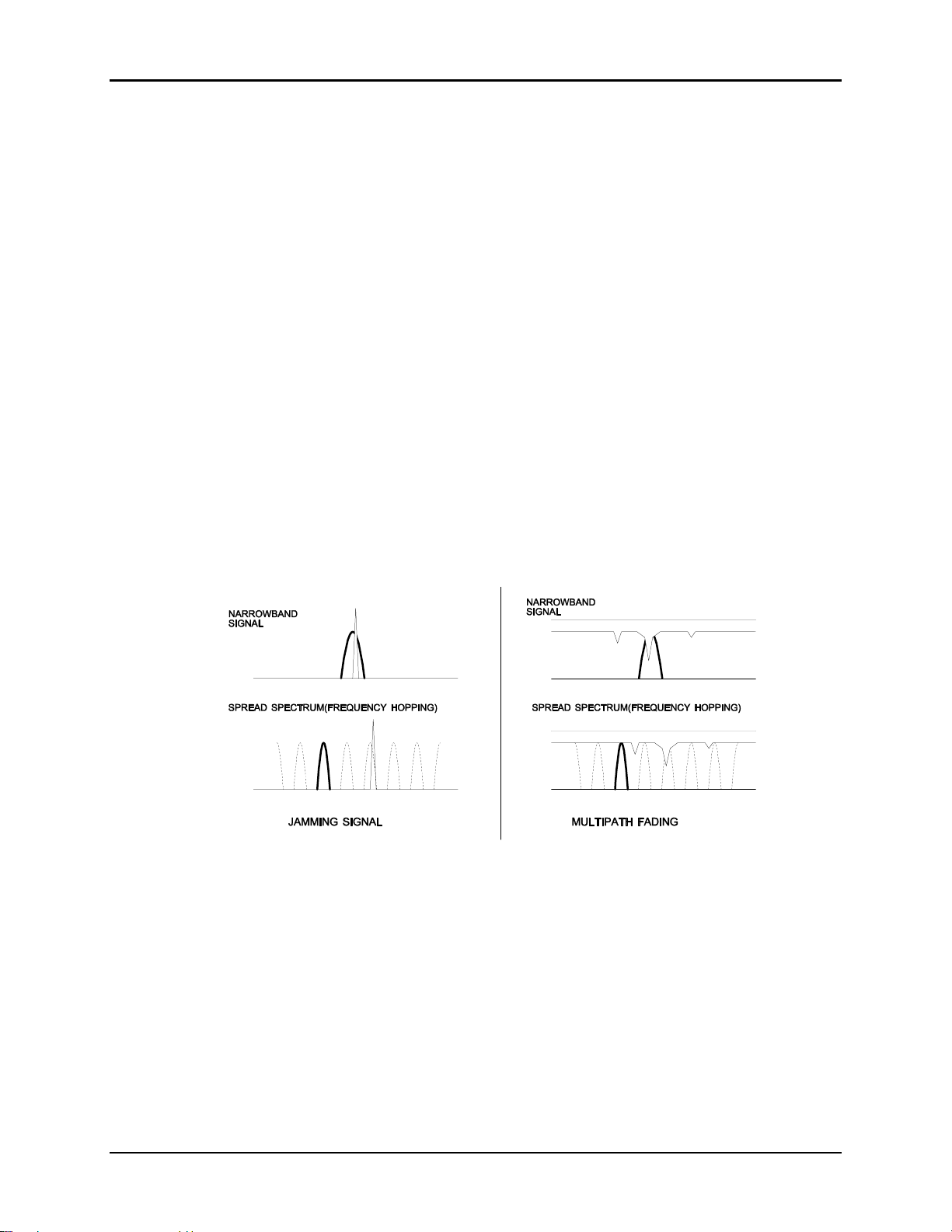
The radio transmission channel is very hostile, corrupted by noise, path loss and
interfering transmissions from other radios. Even in a pure interference-free
environment, radio performance faces serious degradation through a phenomenon
known as multipath fading. Multipath fading results when two or more reflected
rays of the transmitted signal arrive at the receiving antenna with opposing phase,
thereby partially or completely canceling the desired signal. This is a problem
particularly prevalent in indoor installations. In the frequency domain, a multipath
fade can be described as a frequency-selective notch that shifts in location and
intensity over time as reflections change due to motion of the radio or objects within
its range. At any given time, multipath fades will typically occupy 1% - 2% of the
2.4 GHz band. This means that from a probabilistic viewpoint, a conventional radio
system faces a 1% - 2% chance of signal impairment at any given time due to
multipath.
Spread spectrum reduces the vulnerability of a radio system to interference from
both jammers and multipath fading by distributing the transmitted signal over a
larger region of the frequency band than would otherwise be necessary to send the
information. This allows the signal to be reconstructed even though part of it may be
lost or corrupted in transit.
WIT2450
Figure 1
Narrowband vs. spread spectrum in the presence of interference
© 2000- 2005 Cirronet™ Inc 7 M-2450-0000 Rev B
Page 8
1.2. Frequency Hopping vs. Direct Sequence
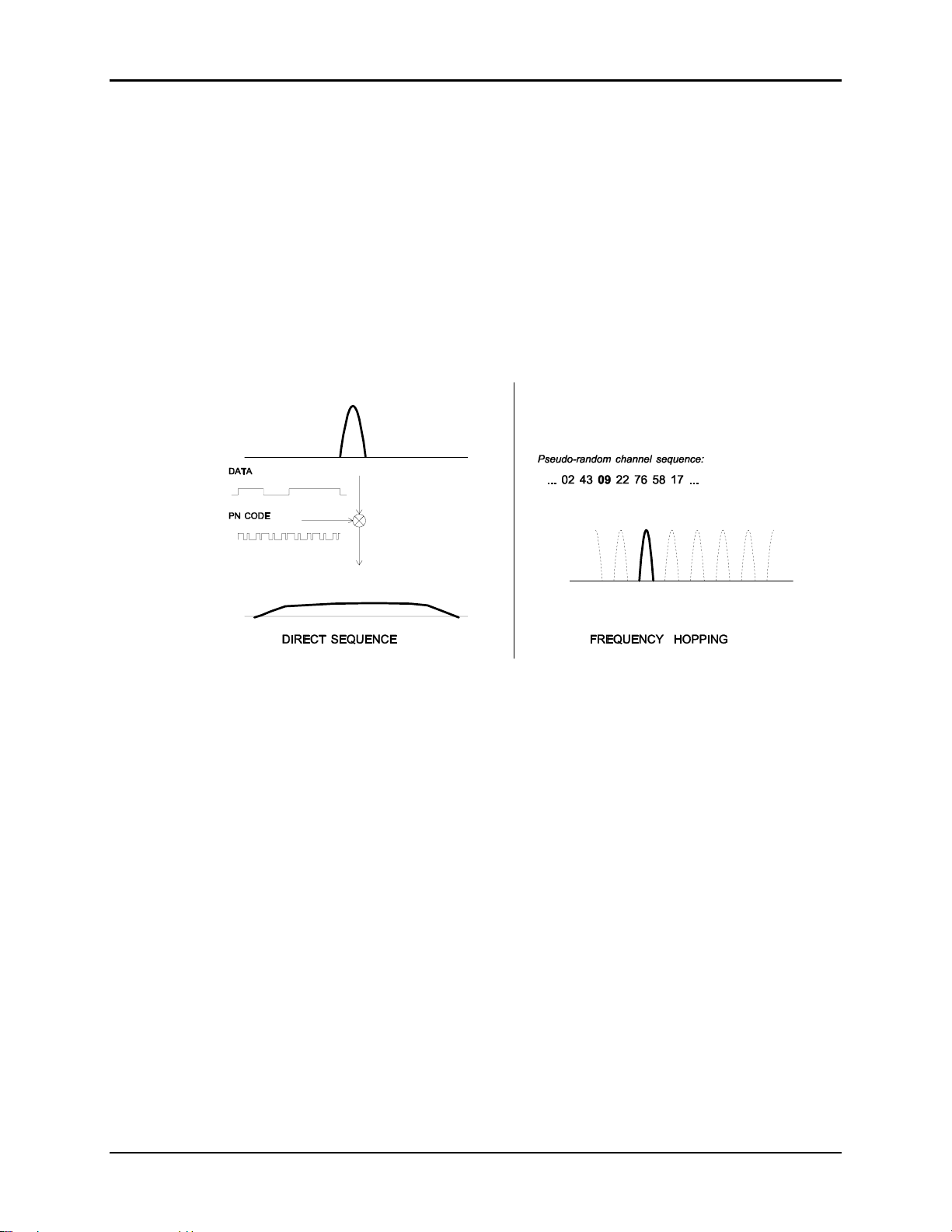
The two primary approaches to spread spectrum are direct sequence (DS) and
frequency hopping (FH), either of which can generally be adapted to a given
application. Direct sequence spread spectrum is produced by multiplying the
transmitted data stream by a much faster, noise-like repeating pattern. The ratio by
which this modulating pattern exceeds the bit rate of the baseband data is called the
processing gain, and is equal to the amount of rejection the system affords against
narrowband interference from multipath and jammers. Transmitting the data signal
as usual, but varying the carrier frequency rapidly according to a pseudo-random
pattern over a broad range of channels produces a frequency hopping spectrum
system.
WIT2450
Figure 2
Forms of spread spectrum
One disadvantage of direct sequence systems is that due to spectrum constraints and
the design difficulties of broadband receivers, they generally employ only a minimal
amount of spreading (typically no more than the minimum required by the regulating
agencies). For this reason, the ability of DS systems to overcome fading and in-band
jammers is relatively weak. By contrast, FH systems are capable of probing the
entire band if necessary to find a channel free of interference. Essentially, this
means that a FH system will degrade gracefully as the channel gets noisier while a
DS system may exhibit uneven coverage or work well until a certain point and then
give out completely.
Because it offers greater immunity to interfering signals, FH is often the preferred
choice for co-located systems. Since direct sequence signals are very wide, they
tend to offer few non-overlapping channels, whereas multiple hoppers may
interleave with less interference. Frequency hopping does carry some disadvantage
in that as the transmitter cycles through the hopping pattern it is nearly certain to
visit a few blocked channels where no data can be sent. If these channels are the
same from trip to trip, they can be memorized and avoided; unfortunately, this is
© 2000- 2005 Cirronet™ Inc 8 M-2450-0000 Rev B
Page 9

WIT2450
generally not the case, as it may take several seconds to completely cover the hop
sequence during which time the multipath delay profile may have changed
substantially. To ensure seamless operation throughout these outages, a hopping
radio must be capable of buffering its data until a clear channel can be found. A
second consideration of frequency hopping systems is that they require an initial
acquisition period during which the receiver must lock on to the moving carrier of
the transmitter before any data can be sent, which typically takes several seconds. In
summary, frequency hopping systems generally feature greater coverage and channel
utilization than comparable direct sequence systems. Of course, other
implementation factors such as size, cost, power consumption and ease of
implementation must also be considered before a final radio design choice can be
made.
As an additional benefit, RF spectrum has been set aside at 2.4 GHz in most
countries (including the U.S.) for the purpose of allowing compliant spread spectrum
systems to operate freely without the requirement of a site license. This regulatory
convenience alone has been a large motivation for the industry-wide move toward
spread spectrum.
© 2000- 2005 Cirronet™ Inc 9 M-2450-0000 Rev B
Page 10

2. RADIO OPERATION
2.1. Synchronization and Registration
As discussed above, frequency hopping radios periodically change the frequency at
which they transmit. In order for the other radios in the network to receive the
transmission, they must be listening to the frequency over which the current transmission
is being sent. To do this, all the radios in the net must be synchronized and must be set to
the same hopping pattern.
In point-to-point or point-to-multipoint arrangements, one radio module is designated as
the base station. All other radios are designated remotes. One of the responsibilities of
the base station is to transmit a synchronization signal to the remotes to allow them to
synchronize with the base station. Since the remotes know the hopping pattern, once they
are synchronized with the base station, they know which frequency to hop to and when.
Every time the base station hops to a different frequency, it immediately transmits a
synchronizing signal.
When a remote is powered on, it rapidly scans the frequency band for the synchronizing
signal. Since the base station is transmitting over 86 frequencies and the remote is
scanning 86 frequencies, it can take several seconds for a remote to synch up with the
base station.
Once a remote has synchronized with the base station, it must request registration from
the base station. The registration process identifies to the base station the remotes from
which transmissions will be received and not discarded. Registration also allows tracking
of remotes entering and leaving the network. The base station builds a table of serial
numbers of registered remotes.
To detect if a remote has gone offline or out of range, the registration can be “renewed”
once every 256 hops. Registration is completely automatic and requires no user
application intervention. When the remote is registered, it will receive several network
parameters from the base. This allows the base to automatically update these network
parameters in the remotes over the air. Once a parameter has been changed in the base, it
is automatically changed in the remotes. The parameters that are automatically changed
are hop duration and the duty cycle.
At the beginning of each hop, the base station transmits a synchronizing signal. After the
synchronizing signal has been sent, the base will transmit any data in its buffer unless
data transmit delay has been set. The data transmit delay parameter allows for the
transmission of groups of continuous data in transparent mode (protocol mode 00H). The
amount of data that the base station can transmit per hop is determined by the base slot
size parameter. The maximum amount of data sent by a base station per hop is 208 bytes.
If there is no data to be sent, the base station will not transmit until the next frequency.
WIT2450
© 2000- 2005 Cirronet™ Inc 10 M-2450-0000 Rev B
Page 11

The operation for remotes is similar to the base station without the synchronizing signal.
The amount of data a remote can send on one hop is dependent upon the hop duration,
the base slot size and the number of registered remotes. 212 bytes per hop is the
maximum data length a remote can transmit per hop, subject to limitations imposed by
the hop duration, the base slot size and the number of registered remotes. A detailed
explanation of this relationship is provided in Section 2.2.3. Minimum data length and
data transmit delay operate the same as with the base station.
Except for the registration process which occurs only when a remote logs onto the
network, the whole procedure is repeated on every frequency hop. Refer to the section
on Modem Commands for complete details on parameters affecting the transmission of
data.
2.2. Data Transmission
The WIT2450 supports two network configurations: point-to-point and point-tomultipoint. In a point-to-point network, one radio is set up as the base station and the
other radio is set up as a remote. In a point-to-multipoint network, a star topology is used
with the radio set up as a base station acting as the central communications point and all
other radios in the network set up as remotes. In this configuration, all communications
take place between the base station and any one of the remotes. Remotes cannot
communicate directly with each other.
2.2.1. Point-to-Point
In point-to-point mode, unless data transmit delay or minimum data length have been set,
the base station will transmit whatever data is in its buffer limited to 208 bytes or as
limited by the base slot size. If the base station has more data than can be sent on one
hop, the remaining data will be sent on subsequent hops. In addition to the data, the base
station adds some information to the transmission over the RF link. It adds the address of
the remote to which it is transmitting, even though in a point-to-point mode there is only
one remote. It also adds a sequence number to identify the transmission to the remote.
This is needed in the case of acknowledging successful transmissions and retransmitting
unsuccessful transmissions. Also added is a 24-bit CRC to allow the base to check the
received transmission for errors. When the remote receives the transmission, it will
acknowledge the transmission if it was received without errors. If no acknowledgment is
received, the base station will retransmit the same data on the next frequency hop.
In point-to-point mode, a remote will transmit whatever data is in its buffer up to the limit
of its maximum data length. If desired, minimum data length and data transmit delay can
also be set, which force the remote to wait until a certain amount of data is available or
the specified delay is exceeded before transmitting. If the remote has more data than can
be sent on one hop, it will send as much data as possible as a packet, adding its own
address, a packet sequence number and 24-bit CRC. These additional bytes are
transparent to the user application if the protocol mode is 00H (which is the default). In
the event a remote has more data to send, the data will be sent on subsequent hops. If the
WIT2450
© 2000- 2005 Cirronet™ Inc 11 M-2450-0000 Rev B
Page 12

WIT2450
transmission is received by the base station without errors, the base station will
acknowledge the transmission. If the remote does not receive an acknowledgment, it will
retransmit the data on the next frequency hop. To the user application, acknowledgments
and retransmissions all take place behind the scenes without the need for user
intervention.
2.2.2. Point-to-Multipoint
In point-to-multipoint mode, data sent from the user application to the base station must
be packetized by the user application unless the remote device can distinguish between
transmissions intended for it and transmissions intended for other remote devices. This is
necessary to identify the remote to which the base station should send data. When the
user packet is received by the remote, if the remote is in transparent mode (protocol mode
0), the packetization bytes are stripped by the remote. In this instance the remote host
receives just data. If the remote is not in transparent mode, the remote host will receive
the appropriate packet header as specified by the remote’s protocol mode. Refer to the
section Protocol Modes for details on the various packet formats.
When a remote sends data to a base station in point-to-multipoint mode, the remote host
does not need to perform any packetization of the data. Remotes can operate in
transparent mode even though the base is operating in a packet mode. The remote will
add address, sequence and CRC bytes as in the point-to-point mode. When the base
station receives the data, the base station will add packetization header bytes according to
its protocol mode setting.
2.2.3. Full Duplex Communication
From an application perspective, the WIT2450 communicates in full duplex. That is,
both the user application and the remote terminal can be transmitting data without
waiting for the other to finish. At the radio level, the base station and remotes do not
actually transmit at the same time. If they did, the transmissions would collide. As
discussed earlier, the base station transmits a synchronization signal at the beginning of
each hop followed by a packet of data. After the base station transmission, the remotes
will transmit. Each base station and remote transmission may be just part of a complete
transmission from the user application or the remote terminal. Thus, from an application
perspective, the radios are communicating in full duplex mode since the base station will
receive data from a remote before completing a transmission to the remote.
2.2.4. Channel Access
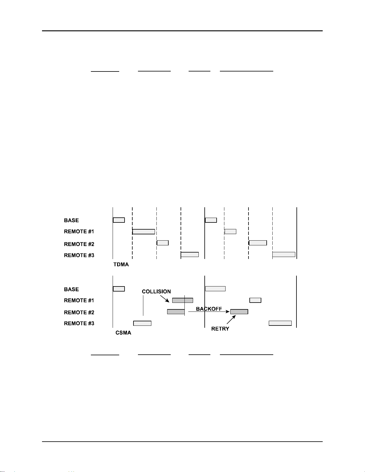
The WIT2450 provides two methods of channel access: CSMA or TDMA. Carrier sense
multiple access (CSMA) is either polling or contention based. Time division multiple
access, TDMA, is slotted or scheduled. A more detailed explanation of Time Division
Multiple Access can be found in the section on TDMA. The default access mode is
CSMA and the default setting is wa0. CSMA protocol is very effective at sorting random
packets of irregular data from a large number of remote nodes. The access mode setting is
© 2000- 2005 Cirronet™ Inc 12 M-2450-0000 Rev B
Page 13
WIT2450
distributed to all remotes in the base status packet, so changing it at the base affects the
entire network.
wa setting
0 (default) CSMA polling
1 CSMA contention
2 TDMA auto slots
3 TDMA fixed slots
4 TDMA override
Description
max PN remote packet size
FFH
FFH
0FH
0FH
0FH
manual, set by pl
manual, set by pl
auto, read from pl
auto, read from pl
manual, set by pl
CSMA
CSMA is less efficient than TDMA in some circumstances, but has the advantage or
requiring no special coordination between remotes. When using CSMA the remotes
simply listen to see if the channel is clear and then transmit. If the channel is not clear the
remote unit will wait a random period of time and try again. This mode works best when
a large or variable number of remotes transmit infrequent bursts of data or in polling
applications where the host will request data and wait for a response prior to moving to
the next remote. In CSMA mode, there is no limit to the number of remote radios that can
be supported.
The illustration below compares TDMA to CSMA.
wa setting
0 (default) CSMA polling
1 CSMA contention
Description
max PN remote packet size
FFH
FFH
manual, set by pl
manual, set by pl
© 2000- 2005 Cirronet™ Inc 13 M-2450-0000 Rev B
Page 14

WIT2450
CSMA “backoff” defines the maximum time that a remote unit will wait after a collision
before attempting to send the packet again (also called the “backoff interval”). CSMA
“persistence” is the probability that a remote unit will transmit immediately rather than
first waiting for a backoff interval.
FFH = 100% probability
00H = 0% probability.
Use these guidelines for setting this parameter:
• For lightly loaded networks, increase persistence to 80H or higher to reduce
latency.
• For heavily loaded networks, reduce persistence to 20H or lower for better
throughput.
Note: For point-to-point applications, set persistence to FFH for maximum throughput and
shortest latency.
The difference between wa mode 0 and mode 1 is that the persistence setting is always
equal to 1. This setting is functionally equivalent to point-to-point for networks with a
single remote. For multipoint networks, this setting assumes only one remote will
attempt to transmit at a time, and should provide the best throughput performance for
polled applications.
In CSMA mode, remotes do not require handles or slots. However, since it is useful in
many applications to receive CONNECT/ DISCONNECT messages, registration is still
available as an option if desired by setting an appropriate 'pn' value. Registration is
considered enabled if the number of remotes as selected by 'pn' is 15 (decimal) or less,
and disabled if 16 or greater. The 'pn' setting is used to determine the number of ACKs
the base requires for a broadcast message, but in practice values above pn0f should
accommodate an unlimited number of remotes.
As an alternative means of tracking connection status in networks with 16 or more
remotes, a re-ranging interval can be set using the remote command 'wv' (by default
disabled at
wvff). This will cause remotes to do a ranging registration every n service
intervals (256 hops), which will produce a CONNECT packet at the base each time. The
host application can track these responses to maintain a list of connected remotes.
If CONNECT messages are enabled, the host will be notified whenever a remote registers
initially. However, since there is no mechanism for providing DISCONNECT
notifications in CSMA mode, this method of tracking whether remotes are linked is not
recommended.
Another method of keeping track of what remotes are in range for CSMA is to
periodically send a ping test request to each remote with a CMD_PUT. This is a
configuration parameter that can be set for a remote to force it to send a burst one or more
pings (zero-byte data packets). Obviously, the base must be using protocol mode for this
method to work. The check must be individually performed for each remote.
© 2000- 2005 Cirronet™ Inc 14 M-2450-0000 Rev B
Page 15

WIT2450
CSMA Algorithm
One advantage of the CSMA mode is that remotes may use unused base slot time to send
data, removing the throughput penalty for allocating a large '
pw' slot size for the base.
The entire remainder of the hop after the base has finished transmitting is available for
the remotes.
The algorithm used to determine if a remote transmits or not is known as p-persistent
CSMA. The "p" in p-persistent refers to the chance of transmission when the channel is
idle, and is represented as a fractional value between 0 and 1. A collision is declared if
either the packet is preempted or no ACK is received from the base at the start of the next
hop.
The random backoff factor is scaled up as the number of consecutive collisions increases
according to the following series: 1, 2, 3, 4, 4, 4... . This says that the first backoff is
either 0 or 1 hops, the second backoff is 0..2 hops, the third backoff is 0..3 hops, and
subsequent backoffs are 0..4 hops. The collision count is reset whenever a data packet is
acknowledged or a successful registration renewal occurs. One drawback of the CSMA
contention mode is that remotes must contend to send ACKs back to the base.
The transmit or persistence probability "p" is set by the pp command. This command
serves double duty to specify the contention slot transmit probability if the network is in
TDMA mode. In CSMA mode, the base propagates the probability setting out to all the
remotes. In TDMA mode, it must be set individually if a non-default value is desired
Note: The factory default value (p=0.625) is adequate and should not need to be
adjusted.
Summary of limitations of CSMA implementation:
• Remotes are limited to only one transmit attempt per hop.
• High turnaround time (aka 'blind spot') means relatively high chance of collision
in heavily loaded networks.
• Backoff combined with maximum of one transmit attempt per hop generally
implies multi-hop average latency.
• Maximum latency cap of 15 hops means some packets will be discarded after
only a small number of attempts.
• Large packets don't get as wide of a random time interval to choose from as small
packets.
© 2000- 2005 Cirronet™ Inc 15 M-2450-0000 Rev B
Page 16

WIT2450
Broadcast Transmissions
The rule for transmitting broadcast packets from the base is:
Send broadcasts until an ACK has been heard from each remote or the 'pr'
attempt limit is reached, whichever comes first.
Note: In CSMA polling mode, networks that have multiple remotes will not be
able to successfully contend to send ACKs, so the 'pr' limit will generally apply.
This could also impact the capability of remotes to reply to a CSMA poll. This is
another reason it may be useful to have a dedicated short slot for contention
networks to ACK on.
ACKs from remotes are also ACKed by the base, so once a remote knows its ACK has
been heard, it doesn't have to keep sending it, which helps reduce network congestion.
The default address for a base in transparent mode is the broadcast address. Remotes can
ACK broadcasts and packets no longer need to be sent redundantly.
TDMA
In TDMA mode, remotes register with the base to acquire ranging information and
receive a handle and slot assignment, which they must periodically renew every 256 hops
(aka a 'service interval').
For applications needing guaranteed bandwidth availability, the TDMA operation of the
WIT2450 can meet this requirement. In the WIT2450 TDMA scheme, each remote has
an assigned time slot during which it can transmit.
wa setting
2 TDMA auto slots
3 TDMA fixed slots
4 TDMA override
Description
max PN remote packet size
0FH
0FH
0FH
auto, read from pl
auto, read from pl
manual, set by pl
When setting up a network, keep in mind that time slot length, maximum packet size and
hop duration are all interrelated. The hop duration parameter will determine the time slot
size and the maximum amount of data that can be transmitted per hop by the remotes.
There is a hard limit of the absolute maximum amount of data that can be sent on any
given hop of 212 bytes regardless of any parameters. (Note that this is different than the
208 byte maximum for the base station.) The base station requires 2.64 ms overhead for
tuning, the synchronization signal and parameter updating, as well as a guard time of
417µs between each remote slot. Thus the amount of time allocated per remote slot is
roughly:
hop duration – base slot – 2.64ms - ( # of registered remotes)·417µs
( # of registered remotes)
© 2000- 2005 Cirronet™ Inc 16 M-2450-0000 Rev B
Page 17

WIT2450
Take for example a network comprised of a base station and 10 remotes. A hop duration
of 10 ms is chosen. We decide that the base station needs to be able to send up to 32
bytes each hop (equivalent to a capacity for the base of ~ 32 kbps). Counting the 2.64ms
overhead for the base packet and making use of the fact that our RF rate is 460.8 kbps,
we determine that the base slot requires approximately:
32·8
460.8kbps
+ 2.64 ms = 3.20
Each remote time slot will be:
10 ms – 3.2 ms – (10)·0.417 ms
10
= 0.263ms
From our RF data rate of 460.8kbps we see that it takes 17.36 µs to send a byte of data,
so each remote will be able to send up to
= 15.1 bytes of data per hop.
0.263 ms
However, the WIT2450 sends data in groups of 4 bytes. Thus, each remote will be able to
send 12 bytes of data. If the WIT2450 is using a protocol mode, the packet overhead is
stripped off (including start and stop bits) before transmission and does not need to be
considered when calculating RF capacity.
So in this example, the total capacity per remote would be:
12 bytes
10 ms
= 12 kbps
If we figure a minimum margin of safety for lost packets and retransmissions of about
20%, we see that this would be more than sufficient to support 9.6 kbps of continuous
data per remote. It is also useful to remember that the asynchronous data input to the
WIT2450 is stripped of its start and stop bits during transmission by the radio, yielding a
"bonus" of 10/8 or 25% in additional capacity.
The above calculations are provided as a means of estimating the capacity of a multipoint
WIT2450 network. To determine the precise amount of capacity, you can actually set up
the radio system and then query the maximum data length from one of the remotes in
control mode to discover its exact setting. Divide this number by the hop duration as
above to get the remote's exact capacity.
© 2000- 2005 Cirronet™ Inc 17 M-2450-0000 Rev B
Page 18

WIT2450
2.2.5. Store and Forward Repeater Operation
The WIT2450 supports operation as a store and forward repeater while also acting as an
end device. A store and forward repeater acts to extend range or avoid obstructions by
receiving data from upstream transmitters and relaying or repeating the data to devices
downstream. The data received from the upstream transmitter will also be output on the
devices serial data ports. This avoids the expense of dedicated repeaters whose only
purpose is to repeat data transmissions it receives. The WIT2450 in S&F mode, listens on
one hop and then relays or repeats the received data on the next hop. Thus the throughput
of data passing through an S&F repeated is cut in half. If the network has more than one
level of repeaters, while the data latency will increase with each level, the data
throughput will not be reduced further.
In S&F mode, there are two types of WIT2450 radios, the Root radio and the Repeater(s).
The Root radio acts as the base radio for the entire network and establishes the timing for
all of the radios in the network (and all other WIT2450 radios). There must be one and
only one Root radio for each network and it is set as the Root using the wb3 command.
All other radios in the network must be informed that an S&F network is being setup.
This is performed using the wb2 command for all radios in the network except for the
Root radio thus making them Store and Forward Repeaters.
Each radio will repeat the data it receives from another radio even if there are no radios
downstream. Thus each radio must be configured with a network number for receiving
data and a network number for repeating the data. The receiving network number is set
using the wn command and the repeating network number is set using the wo command.
Given the long range capability of certain radios, in most situations it is difficult to know
which radios can hear which other radios. Thus, it is advisable to set unique repeating
network numbers for each radio that has other radios downstream. All radios that have no
other radios downstream can have the same repeating network number.
© 2000- 2005 Cirronet™ Inc 18 M-2450-0000 Rev B
Page 19
WIT2450
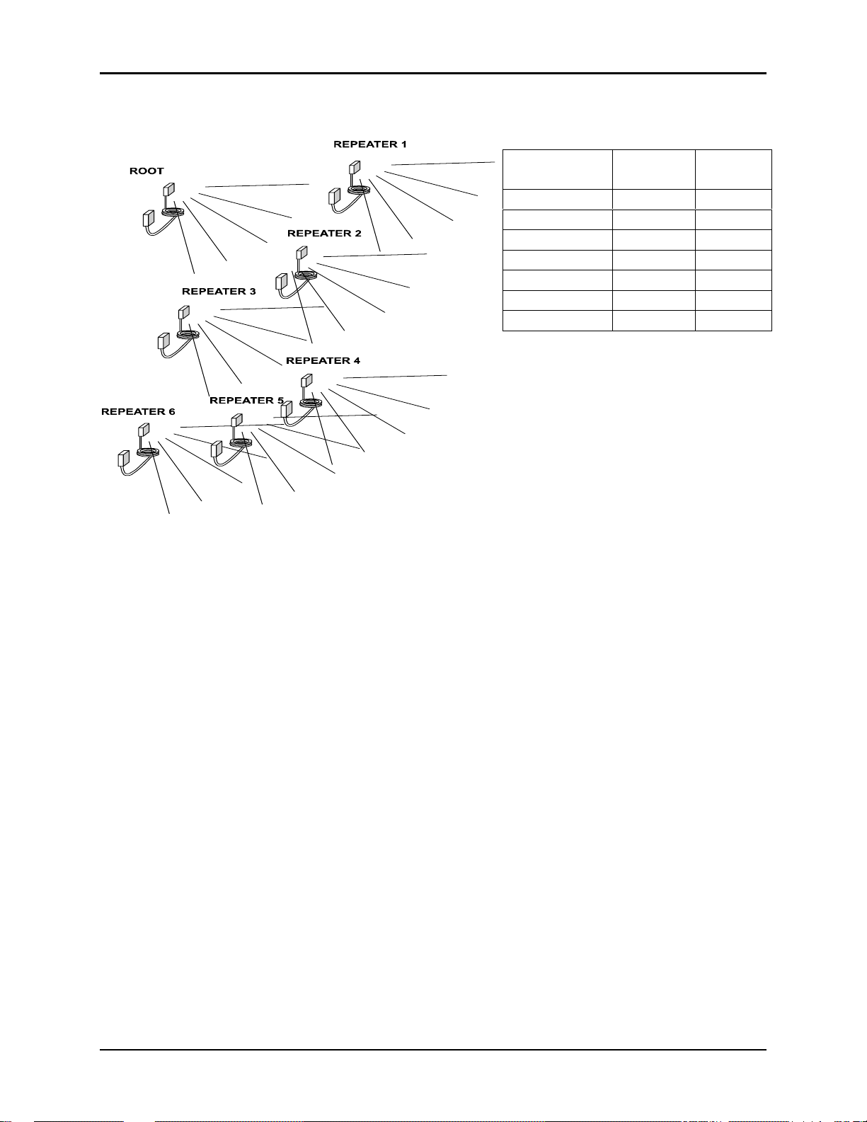
The figure below illustrates a typical radio network with a single layer of repeaters.
Radio
Receive
wn
Repeat
wo
Root 0 NA
Repeater 1 0 8
Repeater 2 0 9
Repeater 3 0 10
Repeater 4 10 11
Repeater 5 10 11
Repeater 6 10 11
Because the repeaters downstream of Repeater 3 might also be able to hear the repeat
transmissions of Repeater 1 or Repeater 2, each repeater radio with downstream
repeaters is assigned a different repeat network number to avoid collisions. Even
though Repeaters 4, 5 and 6 may be in close proximity to each other, since there are
no downstream repeaters, they can use the same repeat network number.
© 2000- 2005 Cirronet™ Inc 19 M-2450-0000 Rev B
Page 20
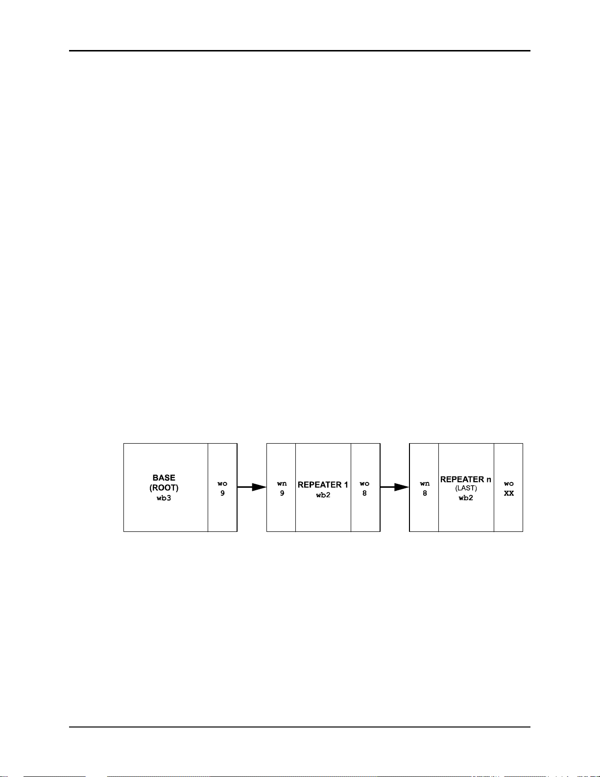
Setup Example:
1. Root Setup: Issue the following commands to the Root, in your system.
2. Intermediate Repeater Setup - Issue the following commands to the Intermediate
Repeater, in your system.
3. Last Repeater Setup - Issue the following commands to the Last Repeater, in your
system.
WIT2450
wb3
wn = wo = downstream network number = 9
m>
wb2
wn = upstream network number = 9
wo = downstream network number = 8
m>
wb2
wn = upstream network number = 9
wo = downstream network number = XX1
m>
4. Verify Link - Verify that each Repeater unit is linked, via DCD indicator. If a unit
is not linked re-check the above settings and run kd4(link status) command, on the
problem unit. It takes a few seconds for the repeaters to synchronize with the system .
5. Send Data - With the CSC program on the Repeaters set to Data-Terminal, verify
that you see data on the repeaters, when you type on the Root/Base node, via the CSC
program.
Note: On the last repeater, the wo value should be set to an unused network number
in your system.
© 2000- 2005 Cirronet™ Inc 20 M-2450-0000 Rev B
Page 21
Bytes, Baud Rate and Hop Time
When Store and Forward mode is entered, through the wb command, the remote
packet length is set to the maximum value, the packet timeout is set to 1 and the
banner mode is set to once after reset (zc1). This is done to allow the longest data
packet to be set without breaking over hop boundaries.
The maximum number of bytes that can be sent as a single message in Store and
Forward mode is determined by baud rate and hop time according to the formula;
baud rate X hop time = Maximum packet size in bytes (max=188 bytes)
10
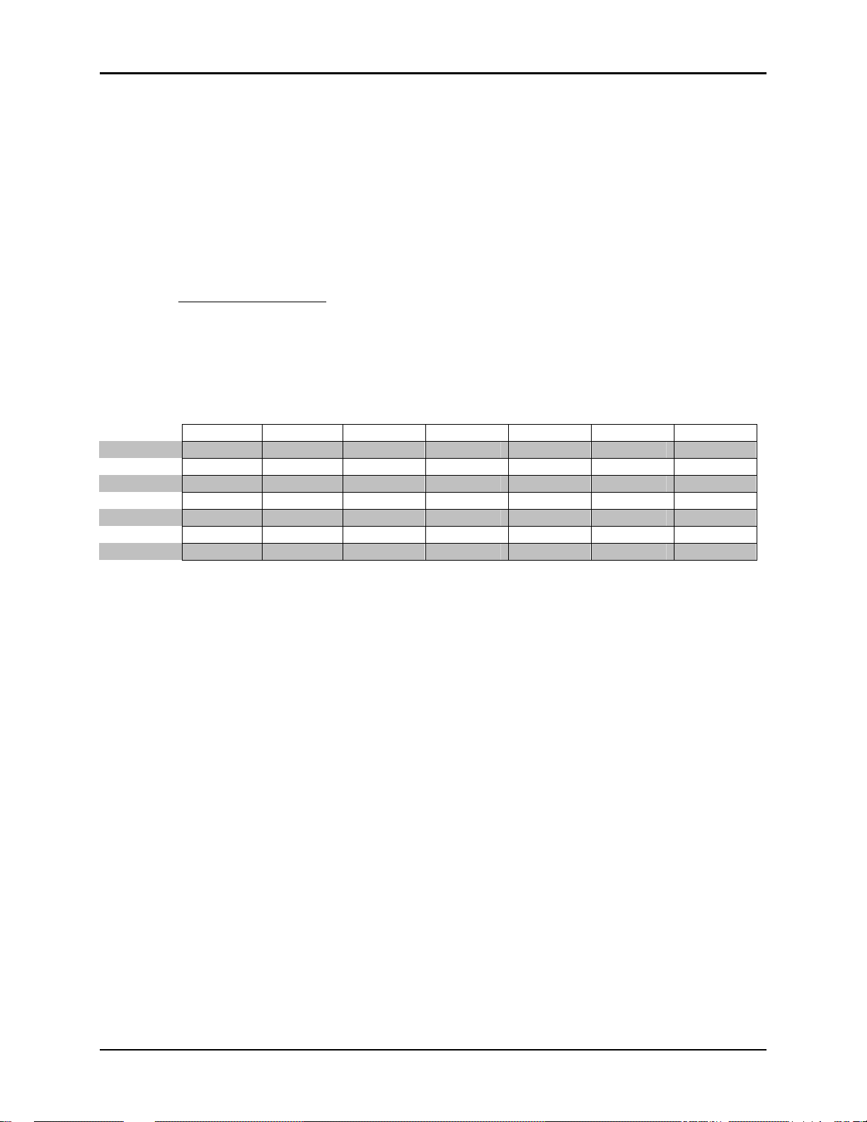
The following table shows examples of baud rate vs. hop time and the resulting
packet length in bytes.
baud rate
115200
57600
38400
28800
19200
14400
9600
2400
default
38 bytes 57 bytes 86 bytes 115 bytes 144 bytes 172 bytes max
19 bytes 28 bytes 43 bytes 57 bytes 72 bytes 86 bytes 101 bytes
12 bytes 19 bytes 28 bytes 38 bytes 48 bytes 57 bytes 67 bytes
9 bytes 14 bytes 21 bytes 28 bytes 36 bytes 43 bytes 50 bytes
6 bytes 9 bytes 14 bytes 19 bytes 24 bytes 28 bytes 33 bytes
4 bytes 7 bytes 10 bytes 14 bytes 18 bytes 21 bytes 25 bytes
3 bytes 4 bytes 7 bytes 9 bytes 12 bytes 14 bytes 16 bytes
0 bytes 1 bytes 1 bytes 2 bytes 3 bytes 3 bytes 4 bytes
3.3ms 5ms 7.5ms 10ms 12.5ms 15ms 17.7ms
hop time
2.3. Modes of Operation
2.3.1. Control and Data Modes
The WIT2450 has two modes of operation: Control mode and Data mode. When in
Control Mode, the various radio and modem parameters can be modified. When in Data
Mode, only data can be transmitted. The default mode is Data Mode. There are two
ways to enter Control Mode. The first way is to assert the Configure (CFG) pin on the
modem. Upon entering Control Mode, the modem will respond with a > prompt. After
each command is entered, the modem will again respond with a > prompt. As long as the
CFG pin is asserted, data sent to the modem will be interpreted as command data. Once
the CFG pin is deasserted, the modem will return to Data Mode.
The second method for entering Control Mode is to send the escape sequence
(all lower case) followed by a carriage return. In the default mode, the escape sequence
is only valid immediately after power up or after deassertion of the Sleep pin on the
modem. The modem will respond in the same way with a > prompt. To return to Data
Mode, enter the Exit Modem Control Mode command, z>, or assert and deassert the
WIT2450
:wit2410
© 2000- 2005 Cirronet™ Inc 21 M-2450-0000 Rev B
Page 22

WIT2450
Sleep pin. There are three modes for the escape sequence, controlled by the Set Escape
Sequence Mode command, zc:
zc = 0 Escape sequence disabled
zc = 1 Escape sequence available once at startup
zc = 2 Escape sequence available at any time (default setting)
The zc2 mode setting is useful if the user application has a need to change the modem
settings "on the fly". In this mode the escape sequence is always enabled and may be
sent at any time after a pause of at least 20ms. The modem will respond in the same way
as when in the default mode. It is necessary to issue the Exit Modem Control Mode
command, z>, before resuming data transmission.
Note: The escape sequence must be interpreted as data until the last character is received
and as such may be transmitted by the modem to any listening modems.
2.3.2. Power Down Mode
To save power consumption for intermittent transmit applications, the WIT2450 supports
a Power Down Mode. Power Down Mode enables the user to achieve exceptionally low
current consumption (typically less than 1 uA) in non-active units. Pin number 14
(fourteen) is a device input, a low voltage on this pin (0-Vdc to 1-Vdc) puts the device in
power down. A high voltage on this pin (3.3-Vdc to 5Vdc) puts the device in normal
operating condition. This mode allows the radio to be powered off while the terminal
device remains powered. After leaving Power Down Mode, the radio must resynchronize with the base station and re-register.
Note: This pin cannot be left unconnected.
If Power Down is not needed, this pin must be tied to 3.3v.
2.3.3. RF Flow Control Mode
Because of slight differences in baud rates between transmitting and receiving hosts,
when sending large amounts of data (100’s of KB) in one direction in a point-to-point
application, it is possible to overrun the receive buffer of the receiving radio. For
example a nominal 115.2Kbaud at the transmitting radio’s host might really be 115,201
and at the receiving radio’s host it might be 115,199. This is similar to a situation where
the transmitting radio is sent data at a higher baud rate than the baud rate at which data is
received by the receiving host. To compensate for the variations in nominal baud rates,
the WIT2450 supports an RF flow control mode for point-to-point operation. In this
mode, when the receive buffer of the receiving WIT2450 is close to full, the receiving
WIT2450 stops acknowledging transmissions. The transmitting radio is set to infinite
retries which invokes the RF flow control mode (See Set Packet Attempts Limit in Section
5.3). The receiving radio will not begin acknowledging transmissions from the
transmitting radio until more room in the receive buffer has become available. This will
cause data in the transmit buffer of the transmitting radio to back up. If it backs up to the
point where the transmit buffer fills up, the transmitting radio will deassert CTS stopping
data from the transmitting radio’s host device. Once room is available in the receiving
© 2000- 2005 Cirronet™ Inc 22 M-2450-0000 Rev B
Page 23

WIT2450
radio’s buffer, the receiving radio will begin acknowledging transmissions from the
transmitting radio allowing the transmitting radio’s buffer to begin to empty which will
cause the transmitting radio to reassert CTS. Either one or both of the radios in a pointto-point installation can be configured for the RF flow control. If this mode is invoked in
a point-to-multipoint installation, communications with all radios will be stopped when
any one radio’s receive buffer becomes full.
2.3.4. Co-Existing with 802.11b Networks
In some cases, if a WIT2450-based network is located in close proximity to an 802.11b
network, the WIT2450-based network can interfere with the 802.11b network. To avoid
causing this interference, the WIT2450 radio supports a selection of hopping patterns that
avoid the various 802.11b direct sequence channels. These limited band hopping patterns
allow WIT2450-based networks to be used with 802.11b networks without impacting the
performance of the 802.11b networks. The hopping pattern is selected using the pe
command. Please refer to the section 5.3 Protocol Commands for details.
2.3.5. European Union Settings
When operating the WIT2450 in France, a limited frequency mode must be selected. The
Pe6 value avoids 802.11b bands 11 & 12 is compliant with the French regulatory
standards of 2400-2450MHz. To select the limited frequency band for operation in
France, at the > configuration mode prompt enter:
pe6<CR>
Save this setting by typing:
m><CR>
The limited frequency operation will take effect immediately and will be saved into
memory for use when power is cycled.
Use of the WIT2450 within the European Union is limited to a maximum transmit power
including antenna gain of 20dBm. If gain antennas are to be used, the low power setting
of the WIT2450 must be selected using the wp command (See Section 5.2 Network
Commands). With the low power setting of 10dBm at the antenna connector, a maximum
of 10dB of antenna gain may be used. With the mid power setting of 18dBm, a
maximum of 2dB of antenna gain may be used. To select low power mode, at the >
configuration mode prompt enter:
wp0<CR>
To select mid power mode, at the > configuration mode prompt enter:
wp1<CR>
To save this parameter in non-volatile memory type:
m>
© 2000- 2005 Cirronet™ Inc 23 M-2450-0000 Rev B
Page 24

3. PROTOCOL MODES
In point-to-point applications, it is generally desired that the radios operate in a
transparent mode. That is, raw unformatted data is sent from the host to the radio and is
received as raw data from the receiving end. The addressing and error detection and
correction are still performed by the radios, but it is transparent to the user application.
To set up a point-to-point network, one radio has to be set up as a base station. When the
radios are powered on, the base station will send out the synchronization signal at the
beginning of each hop. The remote will synchronize with the base and automatically
request registration. Once the remote is registered, the radios can transmit data. Protocol
mode operation is available in point-to-point mode if desired.
If the base station is to be responsible for directing data to a specific remote in point-tomultipoint mode, the data sent to the base station by the user application must adhere to a
packet format. This allows transmissions from the base station to be directed to a specific
remote. Data received by a base station from a remote is similarly formatted to identify
to the user application the remote that sent the transmission. The remotes may still use
transparent mode without formatting to send data to the base, if desired. The protocol
format is selected through the Set Protocol Mode command sp.
Base and remote radios can use protocol modes to insure that a packet is transmitted to
the base without being broken up over multiple hops. The data length value in the data
packet becomes the effective minimum packet length and maximum packet length for that
packet. Note that if the remote data length is set to a number of bytes that is longer than
the number of bytes that can be transmitted by a remote on a single hop, the packet will
be discarded. For the base, this value is set by the Set Base Slot Size command. For
remotes this value is dynamically available through the Get Maximum Data Length
command or may be calculated based on the maximum number of remotes that can ever
be registered at one time. Also note that using protocol modes effectively disables Data
Transmit Delay. This means that a packet will not be transmitted until the entire packet
has been sent to the radio, regardless of the amount of time it takes.
If the remote hosts can determine what data is directed to them in point-to-multipoint
mode, the data can be sent to the base station without using a packet format. In this mode,
the automatic retransmission of unsuccessful transmissions is disabled. This is required
since all of the remote modems will attempt to acknowledge each base transmission when
ARQ is enabled. Transmissions that are received with errors are discarded by the radio.
The remote devices must be able to detect a missing packet and request a retransmission
by the base device.
WIT2450
© 2000- 2005 Cirronet™ Inc 24 M-2450-0000 Rev B
Page 25

WIT2450
3.1. Packet Formats
The byte formats for each packet type are shown in the table below. Packet fields are
organized to fall on byte boundaries. In the case of bit-level fields, most-significant bits
are on the left. Fields marked with <> are required; fields marked with [] are options that
may be enabled for received packets by setting the corresponding sp bitfield. Since these
optional fields are output for status purposes only, packets transmitted from the user
should not include them, regardless of the sp setting.
MRTP
Transmit and receive:
REMT_DATA $E9 $30 [rssi] <length> <0-255 bytes data>
BASE_DATA $E9 $31 <3-byte serial number HML> [sequence] [rssi] <length> <0-255 bytes data>
Receive only:
CONNECT $E9 $32 <3-byte serial number HML> <range>
DISCONNECT $E9 $33 <3-byte serial number HML>
CMD_ACK $E9 $44 <3-byte serial number HML> <location> <value>
CMD_NAK $E9 $45 <3-byte serial number HML>
INSTRUMENTATION $E9 $49 <6-status bytes, see detailed description >
Transmit only:
CMD_GET $E9 $40 <3-byte serial number HML> <parameter>
CMD_PUT $E9 $41 <3-byte serial number HML> <parameter> <value>
3.1.1. Data Packet
This packet carries user data. When data is being sent from a remote to the base, no
registration number is required. Up to 212 bytes (208 for base radios) of user data may
be carried per data packet but no more than is specified by the maximum data length
parameter. The radio will not break up a packet over multiple hops. Packets with a data
length greater than maximum data length will not be sent and will be discarded. This
parameter is variable and depends on the number of remotes currently registered.
© 2000- 2005 Cirronet™ Inc 25 M-2450-0000 Rev B
Page 26
4. MODEM INTERFACE
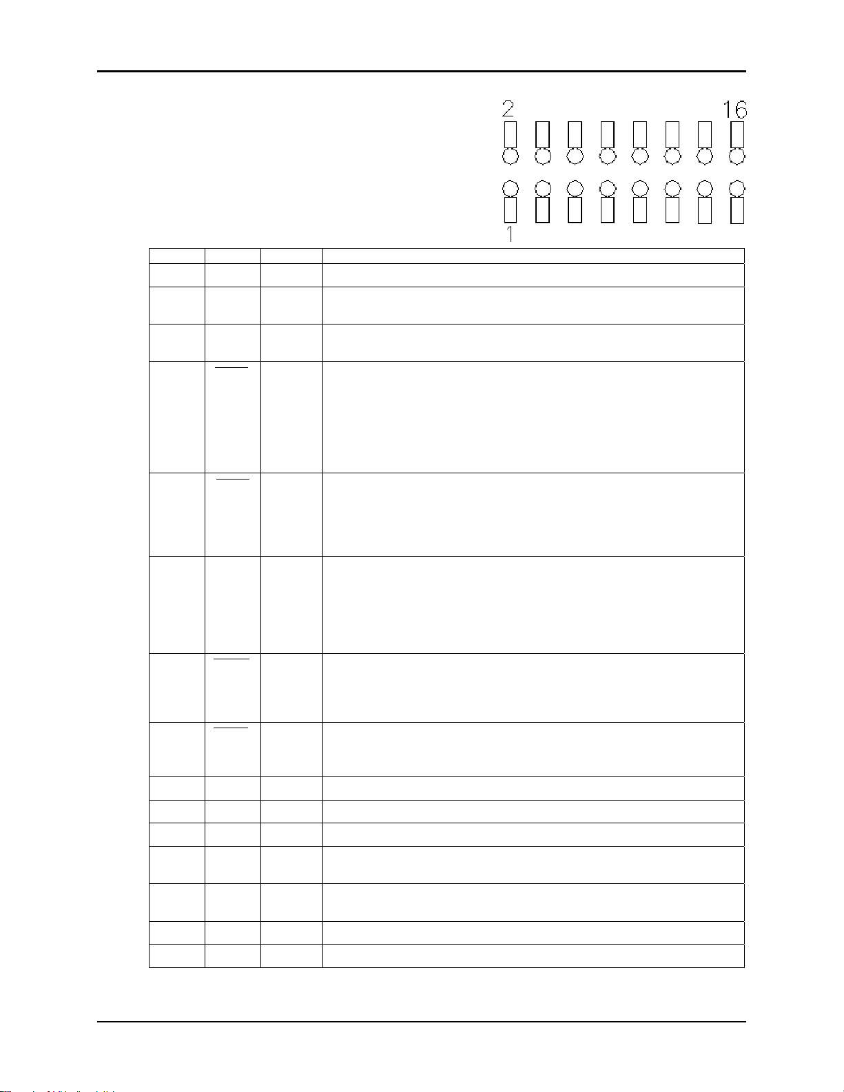
Electrical connection to the WIT2450 is made
through a 16-pin male header on the modem
module. The signals are 3.3-volt signals and form
an RS-232 style asynchronous serial interface.
The table below provides the connector pinout.
Pin Signal Type Description
1 GND - Signal and chassis ground
2 TXD Input Transmit data. Input for serial data to be transmitted. In Control Mode
3 RXD Output Receive data. Output for received serial data. In Control Mode, also
4 Input
CFG
WIT2450
also used to transmit modem commands to the modem.
carries receive modem status from the modem.
Configuration selector. Used to switch between Control and Data Modes.
Normally, CFG will be set for Data Mode. An internal 10K pull-up enables
Data Mode if this signal is left unconnected. Control Mode is also
accessible by transmitting an escape sequence immediately after wake
up or power up.
(0v) 1 = Control Mode
(3.3v) 0 = Data Mode
5 Input
6 DTR Input
7
8
9 RSSI Output Received Signal Strength Indicator (analog signal)
10 Reset Input Resets the radio
11-12 - - Reserved for future use. Do not connect.
13 RSSI
14 Pdwn Input Power Down. 0 = Power down 3.3v to 5v = Active
15 - - Reserved for future use. Do not connect.
16 Vcc - Positive supply. Min 3.3 v, 5.0 v nominal, 10.0 v max.
RTS
DCD
CTS
Strobe
Output
Output
Output Indicates valid RSSI data. (3.3v) 1 = RSSI data valid
Request to send. Gates the flow of receive data from the radio to the user
on or off. In normal operation this signal should be asserted. When
negated, the WIT2450 buffers receive data until RTS is asserted.
(0v) 1 = Receive data (RxD) enabled
(3.3v) 0 = Receive data (RxD) disabled.
Sleeps/wakes radio transceiver. In sleep mode all radio functions are
disabled. At wake up, any user programmed configuration settings are
refreshed from non-volatile memory, clearing any temporary settings that
may have been set.
(3.3v) 1 = Sleep Radio
(0v) 0 = Wake Radio
Data carrier detect. For remotes, indicates the remote has successfully
acquired the hopping pattern of the base station.
(0v) 1 = Carrier detected (synchronized)
(3.3v) 0 = No carrier detected (not synchronized)
Clear to send. Used to control transmit flow from the user to the radio.
(0v) 1 = Transmit buffer not full, continue transmitting
(3.3v) 0 = Transmit buffer full, stop transmitting
(0v) 0 = RSSI data invalid
Must be pulled high for radio to operate. 8.0 v max.
© 2000- 2005 Cirronet™ Inc 26 M-2450-0000 Rev B
Page 27
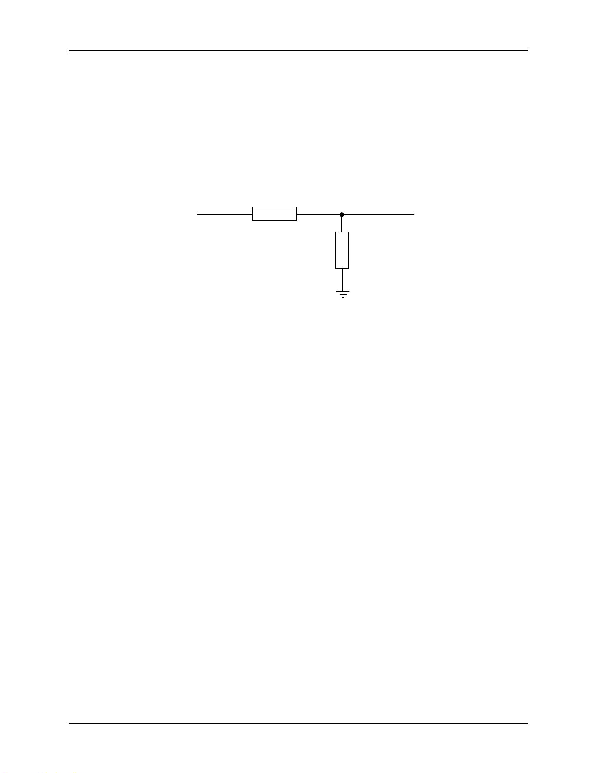
4.1. Interfacing to 5-Volt Systems
The modem interface signals on the WIT2450 are 3.3-volt signals. To interface to 5-volt
signals, the resistor divider network shown below must be placed between the 5-volt
signal outputs and the WIT2450 signal inputs. The output voltage swing of the WIT2450
3.3-volt signals is sufficient to drive 5-volt logic inputs.
From 5v
Output
2200 Ω
4.2. Evaluation Unit and OEM Module Differences
The evaluation unit has an RS-232 transceiver that translates RS-232 level signals to 3.3volt signals for input into the OEM module inside the evaluation unit. A typical
schematic is shown in Appendix 7.5. The OEM module does not have any type of RS232 transceiver and cannot handle the RS-232 voltages. This allows the OEM module to
be easily integrated into any 3.3-volt system without any logic signal translation. In order
for the OEM module to function properly several pins need to be driven low or tied to
ground. Pin 5 (RTS) and pin 6 (DTR) need to be pulled to ground on the 16-pin male
header. If you have the OEM module interfaced to an RS-232 transceiver, RTS and DTR
need to be pulled high on the transceiver side. In the evaluation unit, RTS and DTR are
pulled high on the transceiver side so the evaluation unit will work with these signals not
connected.
4.3. Three Wire Operation
The WIT2450 can be operated in a three wire configuration using just TxD, RxD and
Ground. To operate the WIT2450 in this configuration, the Sleep and RTS signals must
be tied to ground. These signals are pulled up on the WIT2450 module and if left
disconnected will put the radio into sleep mode and RTS will be deasserted. In addition,
Power Down Mode (Pin #14) must be tied high.
The WIT2450 does not support software flow control (XON/XOFF). Thus when using a
three wire configuration, there is no flow control. The radio configuration and/or the
application must insure the transmit and receive buffers do not overflow. The WIT2450
has a 512-byte transmit buffer and a 512-byte receive buffer. For example, the default
settings for the base slot size and hop duration are
WIT2450
To 3.3v Input
4300 Ω
08H and 90H respectively. The 08H
© 2000- 2005 Cirronet™ Inc 27 M-2450-0000 Rev B
Page 28

base slot size allows the base to send 32 bytes of data per hop. The 90H hop duration
provides a 10ms hop dwell time. These default settings provide a base throughput of
40kbps (Since the over the air transmission is synchronous, the 32kbps synchronous over
the air rate is equivalent to 40kbps asynchronous into the radio serial port). If the base
transmits continuously at a higher rate than this, unless the default settings are changed,
the transmit buffer will eventually overflow. To allow a higher base throughput, either
increase the base slot size or the hop duration or both. A similar analysis needs to be
performed for the remote radios. Refer to Section 2.2.3 TDMA Mode for the remote
throughput calculation.
4.4. Power-On Reset Requirements
The WIT2450 has an internal reset circuit that provides a reset signal to the
microprocessor if the supply voltage to the WIT2450 falls below 2.7-volts. Operation of
the microprocessor at voltages below this voltage is unspecified and can result in
corruption of the program memory. When the radio is first powered on, there is an inrush
current in excess of 250mA. The power supply in the host must be capable of sourcing
this current without the voltage falling below 2.7-volts at the radio. Failure of the power
supply to meet this requirement can result in “motorboating” of the radio where the
inrush current of the radio pulls the supply voltage below 2.7-volts causing the reset
circuit to fire which resets the radio removing the current requirement. Once the voltage
recovers to a level above 2.7-volts, the reset signal is removed from the radio which
causes the inrush current which causes the voltage to drop causing the reset circuit to fire
and so on.
WIT2450
© 2000- 2005 Cirronet™ Inc 28 M-2450-0000 Rev B
Page 29
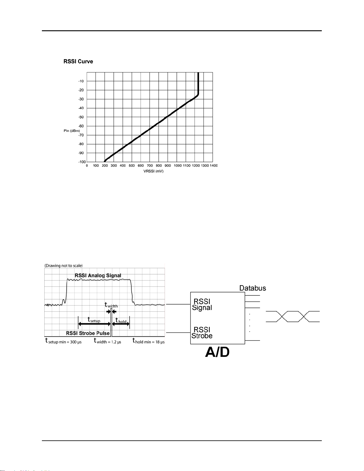
4.6. Received Signal Strength Indicator
Pins 9 and 13 allow real-time assessment of received signal strength. The graph above
shows the relationship of the analog RSSI output voltage from Pin 9 vs. LNA input
power. The RSSI is approximately linear from -100 dBm to -31 dBm. The voltage level
at -100 dBm is .2V and the voltage level at -31 dBm is 1.25V which is the maximum
output voltage as shown in the chart. These values would correspond to 0FH and 60H
when using the wr command in Section 5.2 Network Commands.
The RSSI Strobe output indicates when a valid RSSI signal is present and a high signal
indicates a valid RSSI. The figures below show the relationship between the RSSI signal
and the RSSI Strobe output.
WIT2450
© 2000- 2005 Cirronet™ Inc 29 M-2450-0000 Rev B
Page 30

5. MODEM COMMANDS
The WIT2450 is configured and controlled through a series of commands. These
commands are sent to the modem directly when the modem is in Control Mode when the
modem is in Data Mode if the escape sequence is enabled. The command syntax is the
same for either method, a one- or two-letter command followed by one or more
parameters. The modem will respond with a two-byte message that indicates the new
modem parameter value. The commands are loosely grouped into five different
categories: Serial commands, Network commands, Protocol commands, Status
commands and Memory commands. Each command is described in detail below. In the
descriptions, brackets ([,]) are used to denote a set of optional arguments. Vertical
slashes ( | ) separate selections. For example, given the string wn[?|0..3f], some legal
commands are
a
? option which causes the modem to respond with the current parameter setting, e.g.,
wn? Each modem command must be followed by either a carriage return or a line feed.
wn?, wn0, wn3 and wna. Most commands which set a parameter also have
WIT2450
© 2000- 2005 Cirronet™ Inc 30 M-2450-0000 Rev B
Page 31

5.1. Serial Commands
These commands affect the serial interface between the modem and the host. The default
settings are 9600 bps and protocol mode 0.
Command Description
sd[?|01..BF]
sp[03-1f]
sq[?|0|1..5]
Set Data Rate Divisor
Sets the serial bit rate between the modem and the host. This command takes effect
immediately and will require adjusting the host serial rate to agree. Nonstandard rates
may be programmed by entering a data rate divisor computed with the following formula:
WIT2450
Set Data Rate Divisor
Data Rate Divisor (hex)
2400 bps = BF
9600 bps = 2F (default)
14400 bps = 1F
19200 bps = 17
28800 bps = 0F
38400 bps = 0B
57600 bps = 07
115200 bps = 03
230400 bps = 01
Set Protocol Mode (See section below for command procedure)
Serial Mode Setting
0 = n,8,1
1 = o,8,1
2 = e,8,1
3 = n,7,2
4 = e,7,2
5 = o,7,2
DIVISOR = (460800/RATE)-1
Round all non-integer values down. Note that the new data rate will take effect
immediately but will not be stored in non-volatile memory until the m> command is
issued. If an error is made in the baud rate setting toggling DTR or cycling power to the
WIT910 will cause the previous baud rate to be used.
© 2000- 2005 Cirronet™ Inc 31 M-2450-0000 Rev B
Page 32
WIT2450
Set Protocol Mode
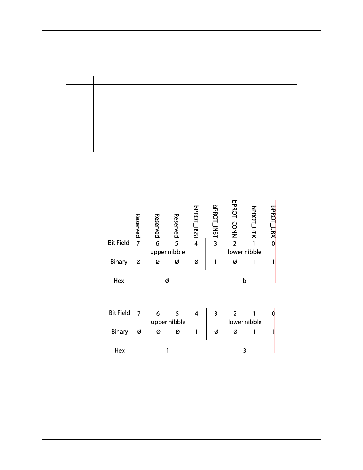
The sp packet mode command uses bitfields shown in the following table. The “lower
nibble” consists of bits 0-3, the “upper nibble” consists of bits 4-7.
Bit Description
0
enable data packets in transmit direction (i.e. TXD from host)
lower
nibble
upper
nibble
1
enable data packets in receive direction (i.e. RXD from radio)
2
enable CONNECT/DISCONNECT packets
3
enable INSTRUMENTATION packets
4
enable RSSI for data packets (rx only)
5
6
7
The structure for the
sp command is as follows:
sp [upper nibble in hex] [lower nibble in hex]
Here is an example to enable packet mode in both directions and instrumentation mode
packets using the command spØb.
A command of sp13 would enable packets in both directions and RSSI mode packets as
shown below.
When using a protocol mode, make sure to count in packet overhead when calculating
network performance.
© 2000- 2005 Cirronet™ Inc 32 M-2450-0000 Rev B
Page 33

WIT2450
The following is the detailed format for the instrumentation packet. If enabled, this is
output once per hop:
$E9 $49 <6-status bytes, see below>
Byte 1 Bitfield
b6-7 Reserved
b4-5 Number of packets in RF queue (0-3)
b3 DCD
b2 RFflow control (of base radio, if a remote)
b1 RF flow control (of this radio)
b0 CTS
Byte 2 RSSI
Byte 3 Number of slots
Byte 4 Channel
Byte 5 TX/RX Status
Byte 6 Programmable (user-selectable through configuration command, defaults t o RSSI_i dl e, i.e. kd9)
The instrumentation packet is available for both base and remote. In the case of the base,
the RSSI and rx status will pertain to the last packet received in the hop, and if the
receiver is triggered by noise, it is possible they will read garbage values. For this reason,
it is preferable to use the RSSI option in received data packets at the base to monitor
these statistics. For consistency with the physical CTS signal, bits b2..b0 are intepreted as
logic low; i.e. '0' = data flow allowed, '1' = data flow disallowed. The b2 base flow
control bit is output for remotes only; for a base it will always read '0'. Bases should use
b1 to monitor their status, if necessary.
Serial Mode Setting
The radio now supports serial modes like those in the Modbus adapter directly. Be aware
that like the sd command, these settings take effect immediately and may require a
change in the serial mode of the terminal program.
© 2000- 2005 Cirronet™ Inc 33 M-2450-0000 Rev B
Page 34

5.2. Network Commands
Network commands are used to set up a WIT2450 network and to set radio addressing
and configuration.
Command Description
wa[?|0-4]
wb[?|0|1|2|3]
WIT2450
Set Access Mode
0 = CSMA polling(default)
1 = CSMA contention
2 = TDMA auto slots
3 = TDMA fixed slots
4 = TDMA override
Set Transceiver Mode
0 = remote (default)
1 = base station
2 = root
3 = repeater
wg[?|0|1]
wl[?|0-ff]
wn[?|0-3f]
wo[?|0-3f]
wp[?|0|1|2]
wr?
wv[?|0-ff]
ww[?|0|1]
Enable Global Network Mode
0 = Link only to hop pattern specified by wn parameter (default)
1 = Link to any hop pattern, regardless of wn parameter
Set lockout key allowing network segr egation beyond network number
0 = default
Set Hopping Pattern or Network Number
0 = default
Set Repeater Network Number, Base Repeater
Set Transmit Power
0 = 10mW / 10dBm
1 = 63mW / 18dBm (default)
2 = 250mW / 24dBm
RSSI - Read Receive Signal Strength
Reranging period
Base DCD Mode Enable
0 = DCD always asserted (default)
1 = Base assert s DCD when pn=1 remote registered
Access Mode
Set 'wa' on the base to determine the channel access mode that the network will use; i.e.
CSMA or TDMA. On the remote, the 'wa' setting is ignored, but the currently selected
mode as broadcast by the base may be read back by using the 'xa' command. CSMA
polling is default. In addition, there is no limit to the number of remote radios that can be
supported.
Set Transceiver Mode
Sets modem operation as either base station, remote, root or repeater. Default is remote.
© 2000- 2005 Cirronet™ Inc 34 M-2450-0000 Rev B
Page 35

WIT2450
Enable Global Network Mode
For networks with multiple base stations, remotes are ordinarily only able to link to one
base station, set by the hopping pattern. Mode 1 enables the global mode that allows
remotes to link to any base station they can hear, acquiring whatever hop pattern is
required. In this mode a remote can only change base stations once it is no longer
registered with a base station.
Set Lockout Key Allows further network segregation beyond the network number. This feature allows multiple co-located networks in which global roaming is enabled. In global roaming, a remote is allowed to link to any base regardless of the network number as long as the lockout key agrees. By using different lockout keys, the bases to which remotes link can be limited or segregated.
Set Hopping Pattern
The WIT2450 has 32 preprogrammed hopping patterns (also referred to as network
numbers). By using different hopping patterns, nearby or co-located networks can avoid
interfering with each other’s transmissions. Even if both networks tried to use the same
frequency, on the next hop they would be at different frequencies. Network numbers
above 32 recycle the same hopping patterns but may be used to distinguish between
networks.
Set Repeater Network Number, Base Repeater
This is the same as Set Hopping Pattern (Set Network Number) but for the Repeating
radios. This allows you to set the downstream network number. Note that the maximum
value of 'wn' supported is 3f, and that this limit may be reduced for certain 'pe' (alternate
frequency band) settings. In the repeater mode, the child network that the repeater
sponsors is specified by 'wo'. The parent network that it connects to first is specified by
'wn'.
Set Transmit Power
The WIT2450 has three preset transmit power levels, 10mW (10dBm), 63mW (18dBm)
and 250mW (24dBm) measured at the RF connector. Control of the transmit power is
provided through this command. Default is 63mW / 18dBm.
Read Receive Signal Strength Indicator (RSSI)
This command reports the relative signal strength averaged over the last 10 hops. This
command returns a one byte value that is proportional to received signal strength and can
range from 00H to FFH. Typical values range from 0FH to 60H where the lower the
number the lower the received signal strength and the higher the number the higher the
received signal strength. This is a relative indication and does not directly correspond to
a field strength number. This is available only at the remotes as the base station is the
only source that transmits on a regular basis. Plus, in a point-to-multipoint network the
base will receive different signal strengths from each remote.
© 2000- 2005 Cirronet™ Inc 35 M-2450-0000 Rev B
Page 36

WIT2450
Set Reranging period
To aid in mobile applications, remotes can recompute the DX range compensation factor
periodically, if desired. The 'wv' command can be used to specify a RerangingPeriod,
which is the number of service intervals between reranging attempts. For example,
setting 'wv4' will cause reranging to occur every 1024 hops (= 10s for 10 ms hop
duration). Reranging is induced by forcing the radio to the LinkStatus=1 state, which is
equivalent to the state just after synchronizing to a new base. If full handle registration is
enabled, the radio will pause in transmitting data to request a new handle. If only ranging
registration is in effect, the remote will just send a ranging registration request. In either
case, a CONNECT packet will be produced if protocol mode is enabled, just as if it were
a first-time registration.
Base DCD Mode Enable
Since the most general application for WIT radios is in a multipoint network, normally
DCD is always asserted at the base. There is an optional mode that may be enabled for
point-to-point networks by setting 'ww1'. This will assert DCD whenever one or more
remotes are registered. For point-to-point use, 'pn' should be set to 1. The default is
'ww0'.
© 2000- 2005 Cirronet™ Inc 36 M-2450-0000 Rev B
Page 37

5.3. Protocol Commands
These commands can be used to tune the transceiver for optimum transmission of data
across the RF link. For most applications, the default values are adequate.
Command
pe[?|0-A]
ph[?|00-fe]
pk[?|00-d0]
pl?
pn[?|01-3e]
pr[?|00-ff]
pt[?|00-ff]
pw[?|00-2f]
(base only)
(remote only)
(base only)
(base only)
WIT2450
Set Alternative Frequency B and
0 = FCC/ETSI operation. (2400.2 – 2474.5MHz) (default)
1 = (2431.3 – 2474.5 MHz) Avoids 802.11b bands 1 & 2
2 = (2400.2 – 2409.7 & 2440.8 – 2474.5 MHz) Avoids bands 3 & 4
3 = (2400.2 – 2418.3 & 2449.4 – 2474.5 MHz) Avoids bands 5 & 6
4 = (2400.2 – 2428.7 & 2459.8 – 2474.5 MHz) Avoids bands 7 & 8
5 = (2400.2 – 2437.3 & 2468.4 – 2474.5 MHz) Avoids bands 9 & 10
6 = (2400.2 – 2452.0 MHz) Avoids bands 11 & 12 (French compliant)
*** Only 16 networks are supported for pe7 and above ***
7 = (2421.7 – 2446.8 MHz) Avoids bands 1, 10, 11 & 12
8 = (2457.2 – 2449.4 MHz) Avoids bands 1 - 6
9 = (2400.2 – 2426.1 MHz) Avoids bands 6 - 12
A = (2431.3 – 2456.3 MHz) Avoids bands 1, 2, 3 & 11
Set Hop Duration
90H = default (=10ms)
Set Minimu m Data Lengt h
01 = default
Get Maximum Data Length (read only)
D4 = default (=212 bytes)
Set Maximum N umber of Remo t es
8 = default (=8 remotes)
Set Packet Attempts Limit
8 = default
FF = infinite retry (RF flow control point-to-point only)
Set Data Transmit Delay
00 = default
Set Base Slot Size
8 = default (=32 bytes)
Description
Note: Incorrect setting of these parameters may result in reduced throughput or loss of data packets.
© 2000- 2005 Cirronet™ Inc 37 M-2450-0000 Rev B
Page 38

WIT2450
Set Alternative Frequency Band
This setting should be set to 0, for FCC-compliant operation in the US (this is the
default). When set to 1, avoids 802.11b bands 1 & 2. When set to 2, avoids 802.11b
bands 3 & 4. When set to 3, avoids 802.11b bands 5 & 6. When set to 4, avoids 802.11b
bands 7 & 8. When set to 5, avoids 802.11b bands 9 & 10. When set to 6, avoids 802.11b
bands 11 & 12 and is also compliant with French regulatory standards. When set to 7,
avoids 802.11b bands 1, 10, 11 & 12. When set to 8, avoids 802.11b bands 1 through 6.
When set to 9, avoids 802.11b bands 6 through 12. When set to A, avoids 802.11b bands
1, 2, 3 & 11. If the WIT2450 is to be used in close proximity to 802.11b networks, these
alternative hopsets can be used to avoid interfering with the 802.11b networks.
Note: This parameter affects the setting of wn (Hopping Pattern).
Set Hop Duration
Sets the length of time the transceiver spends on each frequency channel. A smaller
value will allow the remote to lock on to the base signal faster at system startup, and will
generally decrease packet latency. A larger value increases network capacity, due to
decreased overhead in channel switching. The hop duration is specified in 69.4µs
increments. The default value of 90H corresponds to a duration of 10ms. The maximum
value of FEH is 17.627ms. For best results, do not specify a duration of less than 3 ms.
This value only needs to be set in the base which broadcasts the parameter to all remotes.
However, link time can be reduced if this value is also programmed into the remotes,
which use it as a starting value when scanning for the base.
Set Minimum Data Length
This sets the minimum threshold number of bytes required to form a packet in transparent
mode. The radio will wait until the data transmit delay elapses before sending a data
packet with less than this number of bytes. Can be used to keep short, intermittent
transmissions contiguous. In packet modes, the length parameter in the data packet will
override this value (See Section 3.1). This value is subject to the maximum data length
even in packet mode. See Get Maximum Data Length below.
Get Maximum Data Length (remote only, read only)
This parameter indicates the largest number of bytes that a remote will transmit per hop,
based on the size of the slot it has been allocated by the base. In general more remotes
mean less data can be transmitted per remote. By reading this parameter and dividing by
the hop duration, the remote's data rate capacity can be determined. Attempting to send
protocol mode packets longer than maximum data length will result in the packet being
discarded without being sent. See Section 2.3.3 on the tradeoffs between hop duration
and data length.
Set Maximum Number of Remotes (base only)
This parameter limits the number of remotes that can register with a given base. The
default is 62 remotes which is the maximum number of remotes that can be registered
with a base at one time. This command is useful when used in conjunction with global
roaming for load balancing when base stations are collocated. It is also useful to assure a
minimum remote throughput.
© 2000- 2005 Cirronet™ Inc 38 M-2450-0000 Rev B
Page 39

WIT2450
Set Packet Attempts Limit
If ARQ Mode is set to 0, sets the number of times the radio will attempt to send an
unsuccessful transmission before discarding it. If ARQ Mode is set to 1, it is the number
of times every transmission will be sent, regardless of success or failure of a given
attempt. When this parameter is set to FFH, RF flow control mode is entered for
transmissions from the radio (See Section 2.3.4). This mode can be entered for one or
both radios in a point-to-point system. When used in a point-to-point system the wu
parameter should be set to 1. Using this mode in a point-to-multipoint system will stop
transmissions to all radios when any one radio has a full buffer or if the base radio
attempts to send data to a remote that has recently (<2.5 seconds) left the range of the
base.
Set Data Transmit Delay
When used in conjunction with the minimum data length parameter, this sets the amount
of time from the receipt of a first byte of data from the host until the radio will transmit in
transparent mode. Default is 00H which causes transmission to occur without any delay.
When a host is sending a group of data that needs to be sent together, setting this
parameter will provide time for the group of data to be sent by the host before the radio
transmits. If the length of data to be sent together is longer than the time slot can send,
the data will not be sent together but will be broken up over multiple hops. The length of
time the radio will wait is equal to the specified value times the hop duration.
Set Base Slot Size (base station only)
Sets the amount of time allocated for transmission on each hop for the base station time
slot in 69.4µs increments, corresponding to 4 bytes per unit. Maximum value is 34H
which corresponds to 208 bytes. If using a protocol mode, attempting to send a packet
with a length longer than this setting will cause the packet to be discarded.
© 2000- 2005 Cirronet™ Inc 39 M-2450-0000 Rev B
Page 40

5.4. Status Commands
These commands deal with general interface aspects of the operation of the WIT2450.
Command
zb[?|0|1]
zc[?|0..2]
zh?
Banner Display Disable
0 = disabled
1 = enabled (default)
Set Escape Sequence Mode
0 = disabled
1 = once after reset
2 = unlimited times (default)
Read factory serial number high byte.
Description
WIT2450
zi?
zm?
zl?
zr
zs
z>
Display Curre nt Ba nner
Read factory serial number middle byte.
Read factory serial number low byte.
RTS Pin Enable
Sleep Pin Enable
Exit Modem Control Mode
Banner Display Disable
Enables or disables display of the banner string and revision code automatically at powerup. May be disabled to avoid being mistaken for data by the host.
Set Escape Sequence Mode
Enables or disables the ability to use the in-data-stream escape sequence method of
accessing Control Mode by transmitting the string ":wit2410". When this mode is set
to 1, the escape sequence only works immediately after reset (this is the default). When
set to 2, the escape sequence may be used at any time in the data stream when preceded
by a pause of 20 ms. For backwards compatibility with the WIT2400, the string
:wit2400" is also accepted for entering Control Mode. Note that the escape sequence
"
must be interpreted as data by the radio until the last character is received, and as such
will be generally be transmitted to a receiving radio station, if any.
Display Current Banner
Displays the current banner string and revision code.
Read Factory Serial Number High, Middle and Low Bytes.
These read only commands return one of the three bytes of the unique factory-set serial
number, which are also visible in the startup banner.
© 2000- 2005 Cirronet™ Inc 40 M-2450-0000 Rev B
Page 41
5.5. Memory Commands
The WIT2450 allows the user to store a configuration in nonvolatile memory, which is
loaded during the initialization period every time the radio is powered up. Note that
changes to the serial port baud rate from recalling the factory defaults or recalling
memory will not take effect until DTR is toggled or power to the radio is cycled.
Command
m0
m<
m>
m! Display Modified Parameters
Recall Factory Defaults
Resets the WIT2450 to its factory default state. This is useful for testing purposes or if
there is a problem in operation of the system and the configuration is suspect. Use the
Store Memory command afterwards if you wish the factory default settings to be
remembered the next time you cycle power or reset the radio.
Recall Memory
Useful for restoring the power-on settings after experimenting with temporary changes to
data rate, protocol or network parameters, etc.
Store Memory
This command is necessary after any command to change the data rate, transceiver
address, or other radio setting that you wish to make permanent.
Display Modified Parameters
This command lists all parameter settings that are different from the factory default
settings. This will list changed parameters whether or not they have been stored with the
m> command. Note that issuing this command will cause the radio to lose link with the
base and will cause all remotes to lose link when issued to the base radio.
Recall Factory Defaults
Recall Memory
Store Memory
WIT2450
Description
© 2000- 2005 Cirronet™ Inc 41 M-2450-0000 Rev B
Page 42

5.6. Modem Command Summary
Serial Commands
sd[?|00..ff] Set Data Rate Divisor
sp[?|00..14] Set Protocol Mode
sq[?|0|1..5] Set Serial Mode
Network Commands
wa[?|0-4] Set Transceiver Mode
wb[?|0|1|2|3] Set Transceiver Mod e
wg[?|0|1|2] Enable Global Network Modes
wl[?|00..ff] Set Lockout Key
wn[?|00..3f] Set Hopping Pattern
wo[?|00..3f] Set Repeater Network Number
wp[?|0|1|2] Set Transmit Power
wr? Read Receive Signal Strength (remote only)
wv[?|00..ff] Set Reranging Period
ww[?|0|1] Set Base DCD Mode Enable
Protocol Commands
pe[?|0..B] Set Alternative Frequency Band
ph[?|00..fe] Set Hop Duration (base only)
pk[?|00..d4] Set Minimum Data Length
pl? Get Maximum Data Length (remote only, read only)
pn[?|01..3e] Set Maximum Number of Remotes (base only)
pr[?|00..ff] Set Packet Attempts Limit
pt[?|00..ff] Set Data Transmit Delay (remote only)
pw[?|00..2f] Set Base Slot Size (base only)
xc [?] Display Parent Base Slot Size (remote only)
Status Commands
zb[?|0|1] Banner Display Disable
zc[?|0..2] Set Escape Sequence Mode
zh? Read Factory Serial Number High Byte
zi? Display Current Banner
zm? Read Factory Serial Number Middle Byte
zl? Read Factory Serial Number Low Byte
zr RTS Pin Enable
zs Sleep Pin Enable
z> Exit Modem Control Mode
Memory Commands
m0 Recall Factory Defaults
m< Recall Memory
m> Store Memory
m! Display Changed Parameters
Note: Brackets ([,]) as used here denote a set of optional arguments. Vertical slashes separa te selections.
For example, given the string wn[?|00..3f], legal commands would be wn?, wn0, wn3, and wn2a.
Most commands which set a parameter also have a ? option which displays the current parameter setting;
e.g., wn?.
WIT2450
© 2000- 2005 Cirronet™ Inc 42 M-2450-0000 Rev B
Page 43

6. WIT2450 DEVELOPER’S KIT
The WIT2450 Developer’s Kit contains two self-contained wireless modems (HN-550s)
built around the WIT2450 OEM module. In addition, two WIT2450 OEM modules are
included in the kit. The self-contained units allow developers to get up and running
quickly using standard RS-232 interfaces without having to build a CMOS level serial
interface. In addition, the self-contained modems include status LEDs to provide modem
status information visually. The built-in battery pack allows the developer to use the
modems without being tethered to a power source. This provides a simple way to test the
range of the radios. Other than the true RS-232 signals of the serial interface, the selfcontained modems operate exactly as the OEM modules.
Connection is made to the HN-550s through a standard DB-9 connector. The HN-550s
are set up as DCE devices requiring the use of a straight-through cable to connect to DTE
devices. The pinout is provided in Section 7.2. The modems can be used with just a
three wire connection. Transmit data, receive data and ground are the three required
connections. Note that in this configuration, no flow control is available as the WIT2450
does not support software flow control.
When the developer’s kit is shipped from the factory, one HN-550 is set up as a base
station and the other is set up as a remote. The interface rate for both modems is set at
9600 bps. The default setting for the network key allows the modems to communicate
without changing any settings. As a quick test, separate the two modems by about 5 feet,
plug in the power and turn the modems on. Do not connect the modems to any device.
The Carrier Detect (CD) LED on the base station will come on immediately. After a few
seconds, the CD LED on the remote will come on. This indicates that the modems have
synchronized and have established a communications link.
An important point to remember is that if the base station is in Sleep mode, no
communications can take place until (1) the base station is taken out of sleep mode and
(2) the remote has synchronized with the base station. As the Sleep signal is brought out
on the pin usually occupied by DTR, connecting the base station to a PC serial port with
DTR de-asserted will put the modem into sleep mode. Some communications programs
will attempt to communicate immediately after asserting DTR. The base station will
transmit this data, but the remote will not be synchronized with the base station and will
not receive the transmission. In this instance, do not connect the Sleep signal to DTR of
the serial port.
WIT2450
© 2000- 2005 Cirronet™ Inc 43 M-2450-0000 Rev B
Page 44
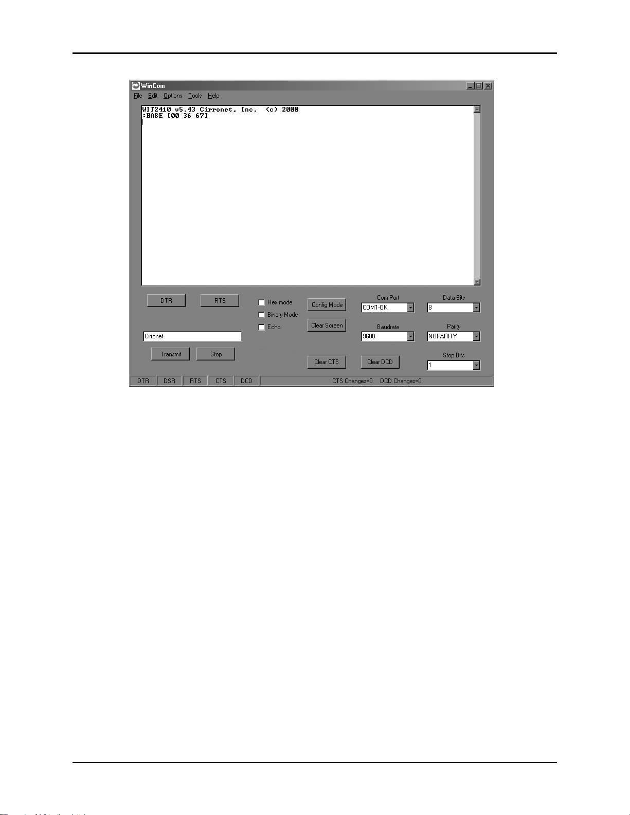
WIT2450
7.0 WinCOM
Provided with the developer’s kit is a configuration program designed especially for
Cirronet’s wireless industrial transceivers or WIT radios. WinCOM is located on the
Manuals and Software CD included in the developer’s kit. Install WinCOM by
navigating to the Software Tools directory on the Manuals and Software CD and doubleclick on wincom2.1.exe follow the installation wizard. Once it has installed, open
WinCOM by double-clicking on the WinCOM icon on the desktop.
© 2000- 2005 Cirronet™ Inc 44 M-2450-0000 Rev B
Page 45
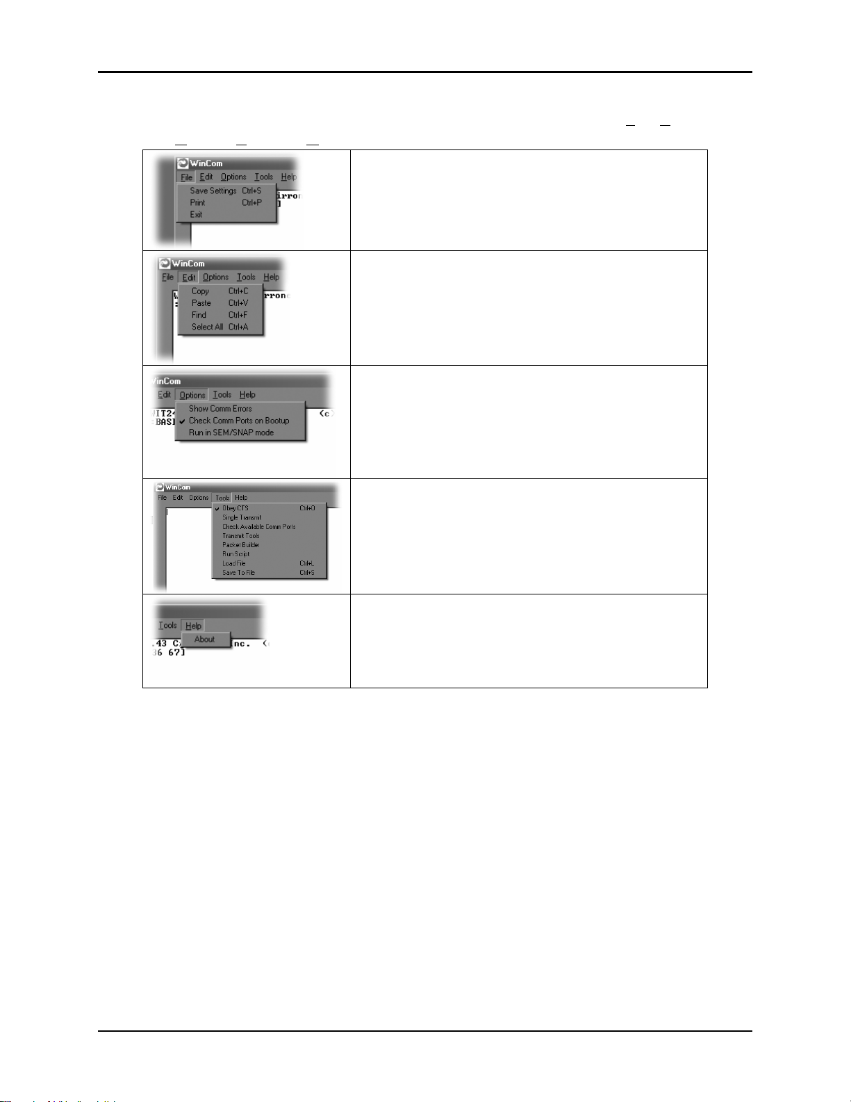
WIT2450
WinCom’s menu structure is typical of Windows conventions with File, Edit,
Options, Tools and Help selections.
Under File, Save Settings (Ctrl S) saves the current
WinCom settings to the hard drive, Print (Ctrl P)
sends whatever text is in the display field to the
printer and Exit terminates the program.
Under Edit, Copy, Paste, Find (search) and Select
All perform the familiar Windows functionality in
typical fashion.
The Options menu contains the selections, Show
Comm Errors which lists any errors encountered in
the PC UART. Check Comm Ports on Bootup tells
WinCom to verify each available port and lists
them as such in the Com Port drop down field.
See the section entitled WinCom Tools for an
explanation of this drop down.
The Help menu displays the About screen which
lists the version number, hardware and software
information for the system being used.
© 2000- 2005 Cirronet™ Inc 45 M-2450-0000 Rev B
Page 46

7.1 Starting the program
When started, WinCOM de-asserts and re-asserts the DTR line to the radio which resets
the radio causing the sign-on banner to be displayed. If the baud rate on the computer
doesn’t match the baud rate of the radio, illegible characters will be displayed. By hitting
the PgUp or PgDn key to change the baud rate, then pressing F1 twice to toggle DTR
(resets the radio) and causes a new banner to be displayed. Continue changing baud rates
in this fashion until a legible banner is displayed as shown below.
The banner indicates the radio firmware version, whether the radio is operating as a base
or a remote and the unique factory serial number of the radio module. If nothing is
displayed in the communications window of WinCOM, verify the COM port and baud
rate settings, then reset the radio (by hitting F1 twice). Cycling power to the radio also
will cause the sign on banner to be displayed unless the banner is disabled via the Banner
Display Disable command (zb0).
WIT2450
The COM port and baud rate can be changed using the drop down menus on the bottom
right. All the available COM ports will be listed in the menu but will have OK or N/A
designated. If another program that uses a COM port is open, that COM port will not be
available for use by WinCOM.
The boxes on the lower right of the WinCOM window provide the status of the COM
port flow control being used to communicate with the radio. Note that DCD is only
asserted by radios configured as remotes when they are linked to a base radio. Radios
configured as bases always assert DCD even if no remotes are linked unless Base DCD is
asserted. Clicking on the DTR or RTS buttons will change the state of the respective
signal line in the COM port.
© 2000- 2005 Cirronet™ Inc 46 M-2450-0000 Rev B
Page 47

WIT2450
The radio is normally in data mode – data that is sent to it from the PC is transmitted over
the wireless connection. When the WinCOM window is active, keys typed on the
keyboard will be sent to the radio and will be transmitted. Unless the “Echo” box is
checked the typed data will not be displayed in the WinCOM window of the sending
radio.
To change configuration parameters, the radio must be put into configuration mode by
clicking on the Config Mode button on the WinCOM window immediately after opening
WinCOM or after cycling power to the radio. Another method is to toggle the DTR by
pressing the F1 key twice, which de-asserts then re-asserts DTR, then pressing the F3 key
(or Config Mode button).
When the radio is in configuration mode, a “>” prompt character is displayed in the
WinCom window as shown above. Configuration parameters are sent to the radio by
entering them in the WinCom window after the “>” prompt and pressing the Enter key.
If an invalid command or value is entered, the radio will respond with “Error” as shown
above Until the command to save the parameters (m>) is issued, the new parameters will
only be valid until power is cycled or DTR is toggled by pressing the F1 key twice.
New parameter values that have been issued are saved to non-volatile memory using the
“m>” command. Refer to the Memory Commands section for details on this and other
helpful memory commands.
To exit configuration mode from the WinCom screen, use the “z>” command and press
Enter as shown below.
The return to the data mode is indicated by an absence of the “>” prompt. Refer to the
Configuration Commands section below for details on all the configurable parameters.
When the radio is linked to another radio, a communications test can be run by clicking
on the Transmit button or pressing the F6 key. Whatever ASCII string is in the Transmit
String window will be transmitted as shown below.
© 2000- 2005 Cirronet™ Inc 47 M-2450-0000 Rev B
Page 48
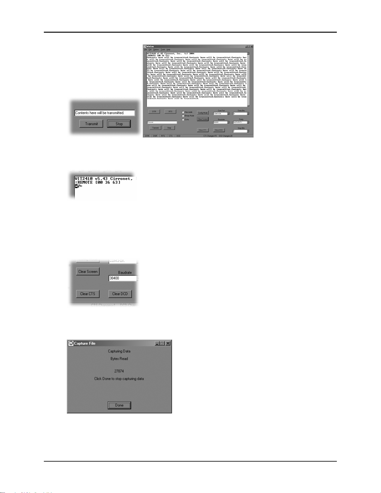
WIT2450
If the other radio is sending data, the received data will be displayed in the WinCOM
window.
If the Binary box is checked, all characters received will be displayed subject to the
limitations of Windows. For example, a carriage return will not return the cursor to the
left side of the window but the character corresponding to 0xd value of the carriage return
will be displayed. Similarly, if the Hex Mode box is checked, all characters are displayed
in hexadecimal format.
The Clear Screen button deletes all the text in the display window. The Clear CTS and
Clear DCD buttons reset the respective changes counters to zero.
After naming the file and clicking on OK, the Capture Data window opens and shows the
amount of data being received. Clicking on Done stops the loading of received data into the file.
© 2000- 2005 Cirronet™ Inc 48 M-2450-0000 Rev B
Page 49

7.2 Function Keys
All of the function key shortcuts are described below:
F1 Toggles state of DTR (Sleep). State is shown in status line.
F2 Toggles state of RTS. State is shown in status line.
F3 Transmits “:wit2400”. Used to enter control mode.
F5 Toggles local echo. If you are transmitting characters through one modem
F6 Toggles stream mode. Causes WinCOM to transmit a repeating pattern of
F8
Toggles binary mode. Displays extended ASCII and control characters.
PgUp Sets data rate of PC serial port to next higher value. Value is displayed in
WIT2450
to another WIT2450, this allows you to see what you are typing.
characters. Useful for testing.
Useful for testing.
status line. Useful when WinCOM is used to change the WIT2450
interface data rate. WinCOM can communicate at new data rate without
having to exit and re-enter WinCOM.
PgDn Sets data rate of PC serial port to next lower value. Value is displayed in
status line.
© 2000- 2005 Cirronet™ Inc 49 M-2450-0000 Rev B
Page 50

7.3 WinCom Tools
There are seven selections under the Tools menu. The first, Obey CTS is useful when
just a three wire connection is made between the radio and the computer. Some PCs
let the CTS input line float. If CTS is not asserted, the PC COM port will not send
data.
WIT2450
Note: Unchecking this selection will have the PC COM port
ignore the state of CTS and transmit data.
When WinCOM’s transmit mode is used, data is sent continuously until the user stops
it by clicking on Stop or pressing F6. If the second tool, Single Transmit, is checked,
clicking the Transmit button will send the Transmit String a single time. There is no
need to click Stop. Clicking on the Transmit button a second time will have the string
transmitted a second time.
The third allows for checking of available Comm Ports and is useful for refreshing
the list.
© 2000- 2005 Cirronet™ Inc 50 M-2450-0000 Rev B
Page 51
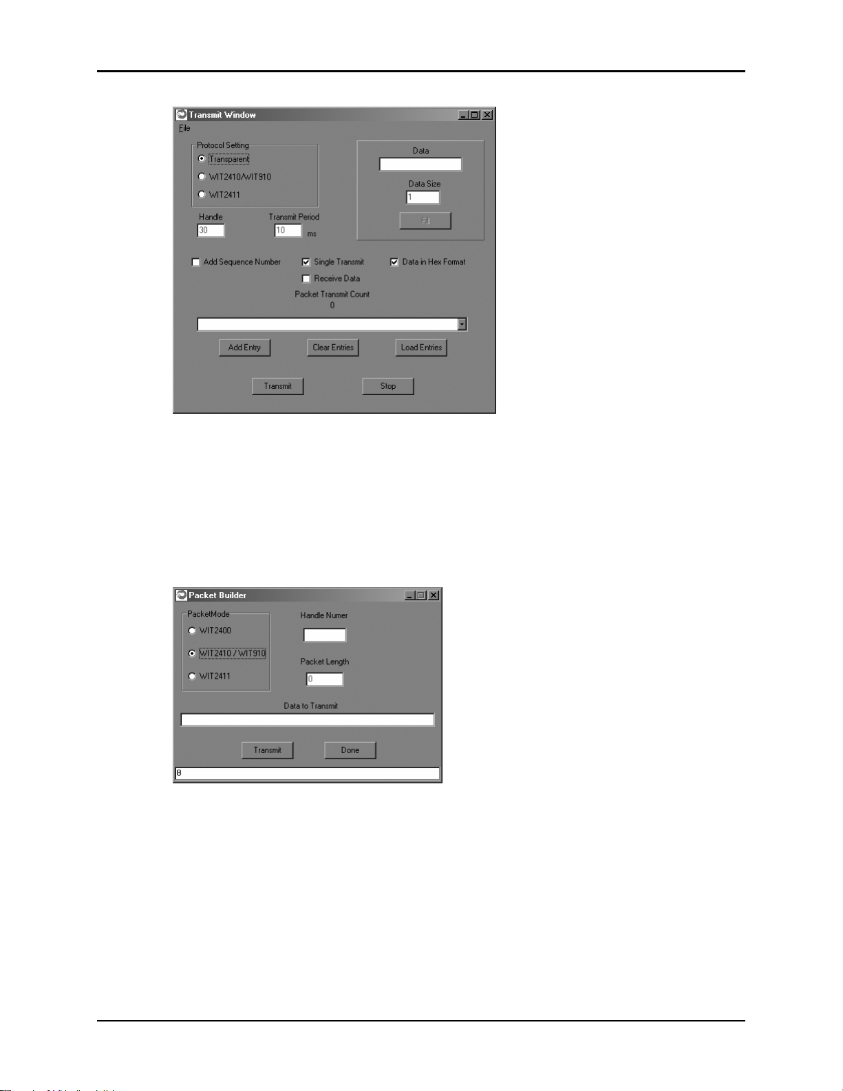
WIT2450
The fourth, Transmit Tools allows for testing of the Transparent, WIT2410/WIT910
or WIT2411 settings. Parameters related to how the transmission will take place can
be set including Handle, Transmit Period, whether or not a Sequence Number should
be added, if the Transmission will be continuous or one time, if the data should be
sent in Hex Format and whether or not data can be received. Data is entered into the
Data field, then Data Size can be set and clicking Fill loads the data into the Transmit
Field. Text strings can now be saved to memory using the save command in the file
menu. Right clicking on the entry field allows for deleting a single entry.
The Packet Builder is an easy way to test the multipoint addressing mode of the
WIT241x radio. Since the WIT241x operates in a star configuration in multipoint
mode, only the base radio needs to address data to specific remotes. All remotes send
data back to the base and do not need to address the data to the base. To send a packet
of data to a specific remote in a multipoint network, enter the handle of the desired
remote in the Handle window. Type whatever data to be transmitted in the Data to
Transmit window. In the bottom window, you will see the entire packet being built as
the data is entered in the windows.
© 2000- 2005 Cirronet™ Inc 51 M-2450-0000 Rev B
Page 52
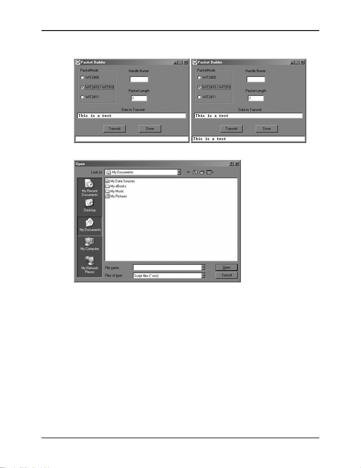
WIT2450
When all the data has been entered, click on the Transmit button to send the data.
WinCOM has the ability to perform any function or sequence of functions WinCOM
can perform through a script file. A script file is a text file that contains one or more
commands and arguments save with a wcr filename extension. Each command is
separated by a carriage return and linefeed. Configuration commands need to have
wait periods between them. The list of commands and their definitions is below:
© 2000- 2005 Cirronet™ Inc 52 M-2450-0000 Rev B
Page 53

7.4 Script Commands
cp <arg> Selects the COM port to use
br <arg> Selects the baud rate to use
do Asserts DTR
df De-asserts DTR
ro Asserts RTS
rf De-asserts RTS
cm Sends configuration escape sequence
oo Obey CTS/RTS
of Do not obey CTS/RTS
sc <cmd(arg)> Send WIT910 format configuration command
wt <arg> Pause for arg milliseconds
An example script file is shown below:
br 115200
df
wt 200
do
wt 200
cm
wt 200
sc m!
WIT2450
This script file sets the baud rate of the PC COM that WinCOM is using to 115,200
kbps, de-asserts DTR, waits 200 milliseconds, asserts DTR, waits 200 milliseconds,
sends the configuration mode escape sequence, waits 200 milliseconds and then sends
the m! command to the radio. What this script file does is set the PC COM port baud
rate to 115.2 kbps, puts the radio in config mode and the issues the command to
display all of the radio parameters that have been changed from factory default. Note
that this script file leaves the radio in config mode. Cycling power or toggling DTR
will return the radio to data mode.
WinCOM prompts you to select the desired .wcr file. Opening the script file causes it
to executed immediately.
© 2000- 2005 Cirronet™ Inc 53 M-2450-0000 Rev B
Page 54
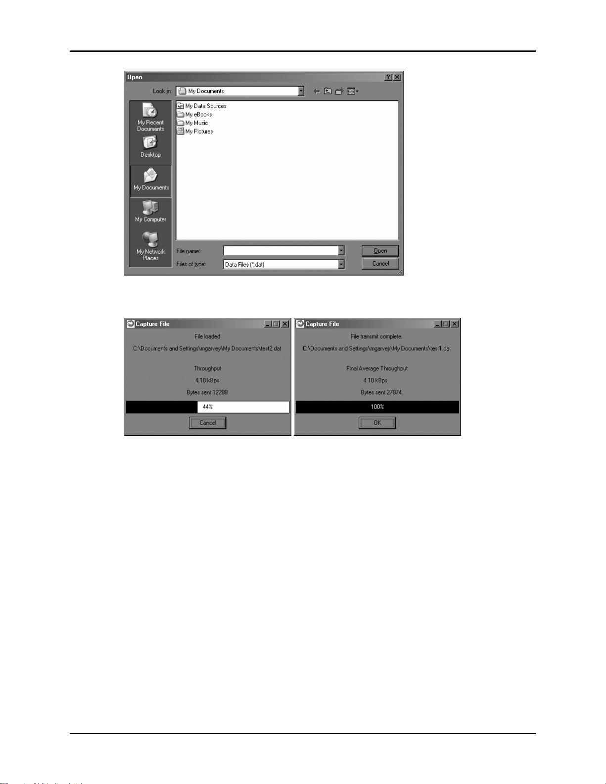
WIT2450
The seventh tool allows the loading of a data file for transmission. Navigate to a file
then click Open and the file is transmitted immediately.
The Capture File dialog displays with a bar showing loading progression. Once the
file has finished transmitting, the Final Average Throughput and Bytes sent numbers
will be displayed.
© 2000- 2005 Cirronet™ Inc 54 M-2450-0000 Rev B
Page 55
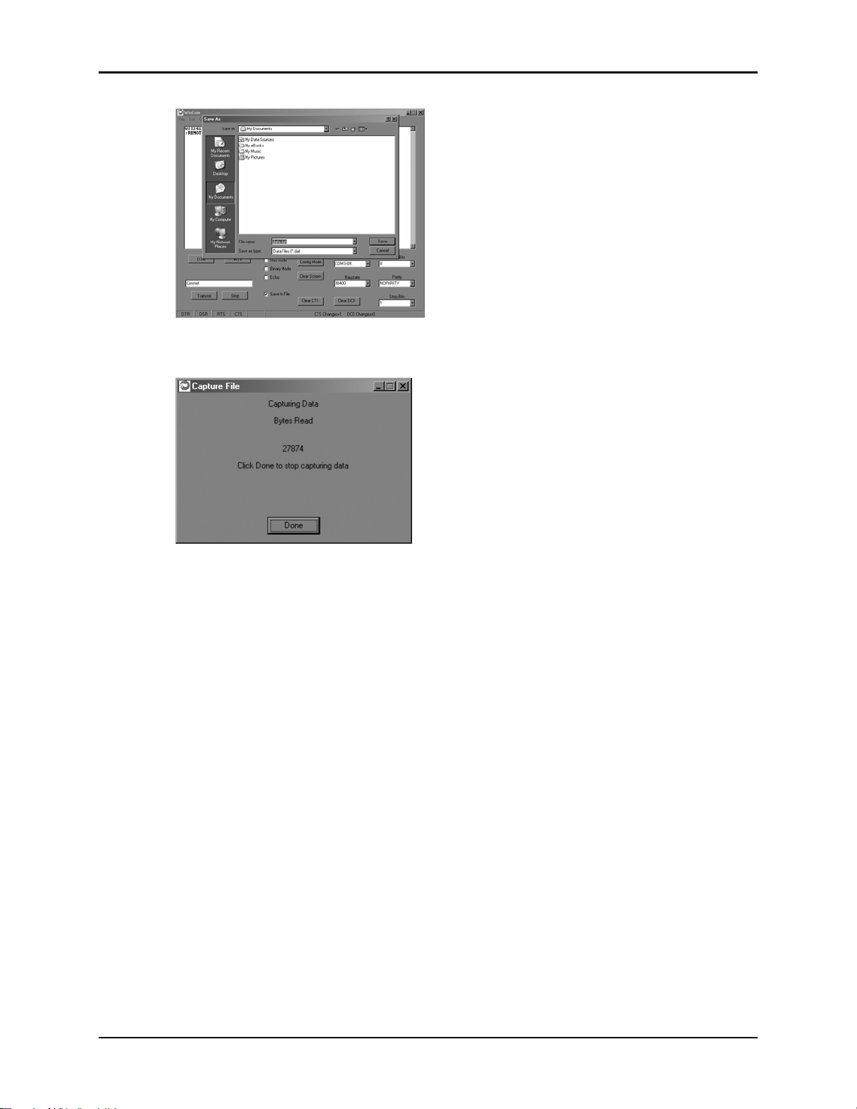
WIT2450
Finally, the eighth tool is Save to File which launches a Save As dialog that allows
any data received to be loaded into a file.
After naming the file and clicking on OK, the Capture Data window opens and shows
the amount of data being received. Clicking on Done stops the loading of received
data into the file.
© 2000- 2005 Cirronet™ Inc 55 M-2450-0000 Rev B
Page 56

7.5 Demonstration Procedure
WIT2450
The procedure below provides a quick demonstration of the WIT241x.
1. Attach a transceiver to each computer, preferably between 5' and 30' apart for
convenience.
2. Start WinCOM running on both computers If you prefer, almost any other serial
communications program such as Procomm or QModem set for 9600 bps will
also work.
3. Turn the radios on and use the function keys to set DTR and RTS to 1 (if you are
using a terminal program other than WinCOM, these are typically set
automatically). The radio should respond by setting both DSR and CTS to 1, and
transmit a short sign-on message including the firmware version and whether the
unit is configured as a base or remote. Watch the states of the hardware control
lines on the status bar as you do this. The DCD indicator should be lit on the base
station. After a few seconds, the remote unit will acquire the base station's signal
and also assert its DCD signal.
4. Access modem control mode for each unit. To access modem control mode, use
the F1 key to toggle DTR to 0 and back to 1 and then press the F3 key, which
sends the ":wit2400" escape sequence. If you are not using WinCOM, simply
turn the radio off and back on and then type ":wit2400" (must be lower case, no
backspace characters). The transceiver should echo back “>” to indicate that you
have entered modem control mode. Check the remote unit's hopping pattern by
entering "wn?" at the prompt. The remote should respond with "0", the default
setting. Check that the base station's hopping pattern matches this by entering
"wn?" at the base station.
5. Exit control mode by entering "z>". Do this for both radios. At this point, you
should be able to type characters into either radio and see them appear at the other
side. If you are using WinCOM, you can press the F6 key to transmit a repeating
test pattern.
6. For a range test, disconnect the remote station from the computer and power
supply. The DCD indicator should remain lit as long as the base station is in
range..
7. Exit WinCOM by pressing the ESC key.
© 2000- 2005 Cirronet™ Inc 56 M-2450-0000 Rev B
Page 57

8. TROUBLESHOOTING
Radio is not responding.
Make sure DTR is asserted to bring the radio out of sleep mode. DSR should be on to
indicate the radio is ready.
Can’t enter modem control mode.
Make sure the host data rate is correct. The WIT2450 defaults to 9600 bps asynchronous.
Evaluation units do not have external access to the CFG_SEL signal; you must use the
:wit2410 power-on escape sequence to access modem control mode. The first characters
typed after the radio wakes up should be the escape sequence. Make sure you type the
colon (:) and enter the letters in lower case; the characters following the colon echo to
show you have typed them correctly. If using the “on-the-fly” escape sequence
command, make sure a pause of at least 20ms precedes the escape sequence.
Remote never detects carrier.
Check that the base station is running, and that the remote is programmed to the same
hopping pattern. Also check that the hop duration for base and remote are the same, and
that the remote has a non-zero link margin.
Carrier is detected, but no data appears to be received.
Make sure that RTS is asserted to enable receive character flow. In a point-to-point
application, if a remote is not receiving data, check that the base's default handle is the
same as the remote's. In a multipoint application, check that the remote is not configured
for protocol mode and that the base is using the correct protocol format and destination
handle.
Radio is interfering with other nearby circuits.
It is possible for the RF energy envelope to be rectified by nearby circuits that are not
shielded for RFI, manifesting as a lower frequency noise signal. If possible, place the
antenna at least 1 foot away from the transceiver module, and 3 feet from other circuit
boards and obstructions. Place sensitive circuits in a grounded metal casing to keep out
RFI.
Sign-on banner or modem control mode prompt is unreadable.
If the problem is repeatable, check whether the data rates between host and transceiver
match.
Range is extremely limited.
This is usually a sign of poor antenna coupling. Check that the antenna is firmly
connected. If possible, remove any obstructions in the near field of the antenna (~3'
radius).
Transmitting terminal flashes CTS occasionally.
WIT2450
© 2000- 2005 Cirronet™ Inc 57 M-2450-0000 Rev B
Page 58

WIT2450
This indicates that the transmitter is unable to reliably get its data across. This may be
the result of an interfering signal, but most often is caused by overloading of the network.
Adjusting the protocol parameters may increase the network efficiency.
Receiving terminal drops characters periodically.
Set the number of retries to a high number and send a few characters. Check that the
transmitted data can get through under these conditions. Sometimes this symptom is
caused by an application that is explicitly dependent on the timing of the received data
stream. The nature of the packetized RF channel imposes a degree of unpredictability in
the end-to-end transmission delay.
Cannot communicate with the OEM module.
Make sure DTR and RTS are asserted. DSR should be on to indicate the radio is ready.
OEM Module is in an unknown state.
Use the m0 command to restore the factory defaults. Note that the serial baud rate must
be set correctly for the module to receive this command.
© 2000- 2005 Cirronet™ Inc 58 M-2450-0000 Rev B
Page 59

9. APPENDICES
9.1. Technical Specifications
9.1.1. Ordering Information
WIT2450M
9.1.2. Power Specifications
Vcc Input Range: 3.3v to 10.0v
Operating Temperature Range: -40°C to +70°C
Current Consumption (Max transmit power @ 5Vcc, 230.4Kbps I/O)
Mode Remote Base Station
Power Down
Receive
Typical Average
Peak (Tx)
9.1.3. RF Specifications
FCC Certification Part 15.247, no license required
ETSI (European) Certification brETSI 300.328, no license required
Rated RF Power +24 dBm
Line-of-site Range approx. 6/10 of a mile w/2dB dipole
Frequency Range 2401 – 2495MHz
Number of Channels 85 US
Receiver Sensitivity -92dBm @ 10-5 BER
Channel Data Rate 460Kbps
IF Adjacent Channel Rejection >55dB
9.1.4. Mechanical Specifications
Weight 28g
Dimensions (incl. shield) 69.85 x 47.75 x 4.57mm
(refer to section 7.6 for mechanical drawing)
RF Connector:
WIT Huber/Suhner: 82 MMCX S50-0-2
Mating Huber/Suhner: 11 MMCX-50-2-3 (straight)
Huber/Suhner: 16 MMCX-50-2-2 (rt. angle)
Data/Power Connector:
WIT Samtec: SAMTEC CLT-108-02-G-D
Mating Samtec: SAMTEC MTMM-108-05-G-D-300
(PCB mount)
WIT2450
.75 mA N/A
40 mA N/A
55 mA 155 mA
150 mA 155 mA
© 2000- 2005 Cirronet™ Inc 59 M-2450-0000 Rev B
Page 60
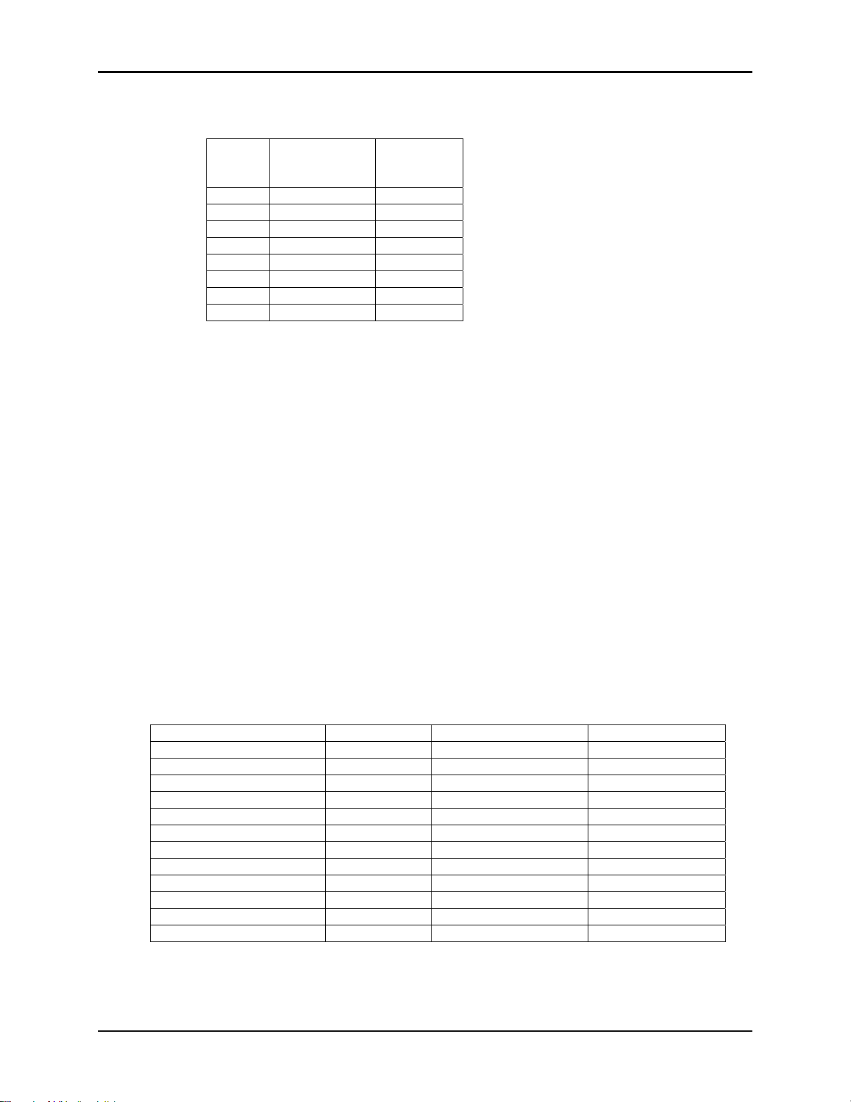
9.2. Serial Connector Pinouts
Signal
GND 1 5
TXD 2 3
RXD 3 2
CFG 4 RTS 5 7
DTR 6 4
DCD 7 1
CTS 8 8
WIT2450
OEM Pinout
The HN-550 is wired as a DCE device and as such can be connected to DTE devices such
as PCs with a straight-through cable. When connecting a HN-550 to a DTE device, a
“null modem” cable is required. To effect a null modem cable, cross-wire TXD and
RXD and connect ground. The HN-550 can operate with just these three wires
connected. However, as the WIT2450 does not support software flow control, there will
be no flow control in this mode. If the DTE device fails to respond, connect DCD from
the HN-510 to the DTR and RTS inputs to activate the DCE device whenever the
WIT2450 asserts carrier.
When connecting to the WIT2450, make sure that all of the inputs (TXD, CFG, RTS and
SLEEP) are terminated for proper operation.
9.3. Approved Antennas
The WIT2450 is designed to ensure that no antenna other than the one fitted shall be used
with the device. The end user must permanently affix the antenna by using an adhesive
on the coupling such as Loctite, or ensure the antenna has a unique coupling. The table
below lists the antennas which can be purchased directly from Cirronet. Contact Cirronet
Technical Support with any questions.
Description Gain Part Number Coupling
24dB Parabolic Dish 24dB PAR2424 N
18dB Parabolic Dish 18dB PAR2418 N
15dB Yagi Directional 15dB YAGI2415 N
14dB Corner Reflector 14dB CORNER2414 N
12dB Omnidirectional 12dB OMNI2412 N
9dB Omnidirectional 9dB OMNI249 N
9dB Corner Reflector 9dB CORNER249 N
6dB Cironnet Patch 6dB PA2400 MMCX
5dB Mobile Mount 5dB MAG245 N
2dB Cirronet Patch 2dB PA2410 MMCX
2dB Rugged Body Mount 2dB RBM242 N
Dipole 2dB RWA249R Reverse SMA
WIT2450
HN-550
DB9
Pinout
© 2000- 2005 Cirronet™ Inc 60 M-2450-0000 Rev B
Page 61

9.4. Technical Support
For technical support call Cirronet at (678) 684-2000 between the hours of 8:30AM and
5:30PM Eastern Time.
WIT2450
© 2000- 2005 Cirronet™ Inc 61 M-2450-0000 Rev B
Page 62
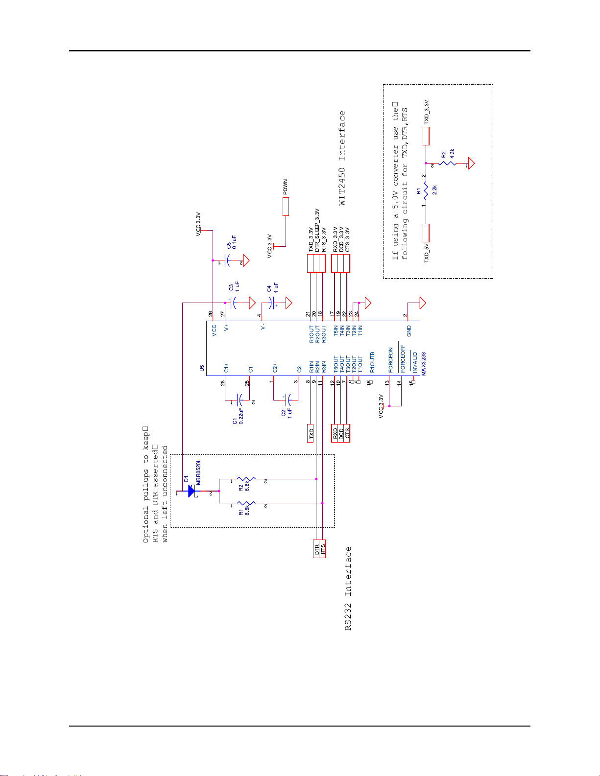
9.5. Reference Design
WIT2450
© 2000- 2005 Cirronet™ Inc 62 M-2450-0000 Rev B
Page 63
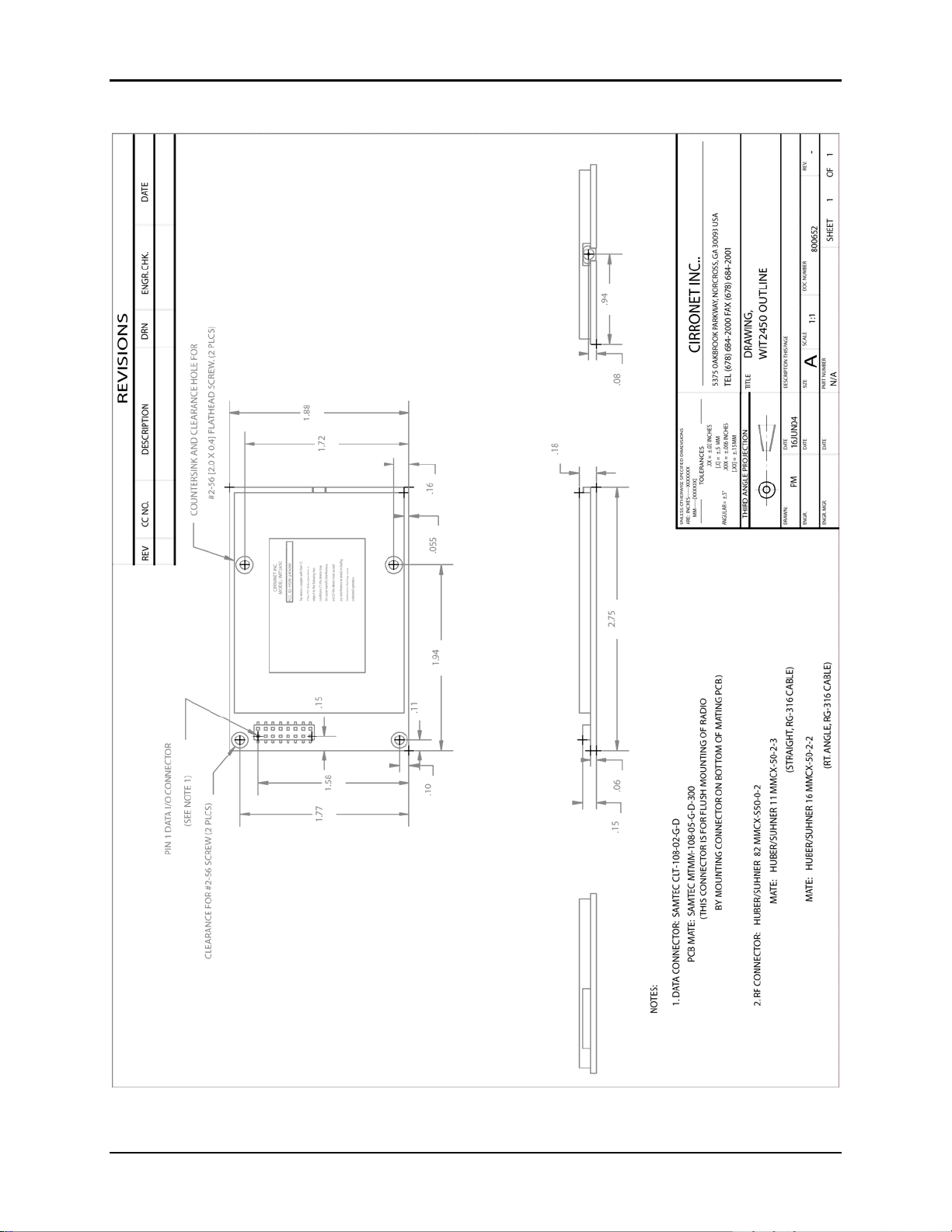
9.6. Mechanical Drawing – WIT2450
WIT2450
© 2000- 2005 Cirronet™ Inc 63 M-2450-0000 Rev B
Page 64

10. WARRANTY
Seller warrants solely to Buyer that the goods delivered hereunder shall be free from
defects in materials and workmanship, when given normal, proper and intended usage, for
twelve (12) months from the date of delivery to Buyer. Seller agrees to repair or replace at
its option and without cost to Buyer all defective goods sold hereunder, provided that
Buyer has given Seller written notice of such warranty claim within such warranty period.
All goods returned to Seller for repair or replacement must be sent freight prepaid to
Seller’s plant, provided that Buyer first obtain from Seller a Return Goods Authorization
before any such return. Seller shall have no obligation to make repairs or replacements
which are required by normal wear and tear, or which result, in whole or in part, from
catastrophe, fault or negligence of Buyer, or from improper or unauthorized use of the
goods, or use of the goods in a manner for which they are not designed, or by causes
external to the goods such as, but not limited to, power failure. No suit or action shall be
brought against Seller more than twelve (12) months after the related cause of action has
occurred. Buyer has not relied and sh all not rely on any oral repr esentation regarding the
goods sold hereunder, and any oral represent ation shall not bind Seller and shall not be a
part of any warranty.
THE PROVISIONS OF THE FOREGOING WARRANTY ARE IN LIEU OF ANY
OTHER WARRANTY, WHETHER EXPRESS OR IMPLIED, WRITTEN OR
ORAL (INCLUDING ANY WARRANTY OR MERCHANT ABILITY OR
FITNESS FOR A PARTICULAR PURPOSE). SELLER’S LIABILITY ARISING
OUT OF THE MANUFACTURE, SALE OR SUPPLYING OF THE GOODS OR
THEIR USE OR DISPOSITION, WHETHER BASED UPON WARRANTY,
CONTRACT, TORT OR OTHERWISE, SHALL NOT EXCEED THE ACTUAL
PURCHASE PRICE PAID BY BUYER FOR THE GOODS. IN NO EVENT
SHALL SELLER BE LIABLE TO BUYER OR ANY OTHER PERSON OR
ENTITY FOR SPECIAL, INCIDENTAL OR CONSEQUENTIAL DAMAGES,
INCLUDING, BUT NOT LIMITED TO, LOSS OF PROFITS, LOSS OF DATA OR
LOSS OF USE DAMAGES ARISING OUT OF THE MANUFACTURE, SALE OR
SUPPLYING OF THE GOODS. THE FOREGOING WARRANTY EXTENDS TO
BUYER ONLY AND SHALL NOT BE APPLICABLE TO ANY OTHER PERSON
OR ENTITY INCLUDING, WITHOUT LIMITATION, CUSTOMERS OF
BUYERS.
WIT2450
© 2000- 2005 Cirronet™ Inc 64 M-2450-0000 Rev B
 Loading...