

Page 1

Cirris 4200 Series
User Manual
for 4200 & 4250 Testers
Page 2

Table of Contents
1. Safety/Support ................................ 4
1.1 Workplace Maintenance .......................4
1.2 Intended Use ...................................4
1.3 Warnings and Precautions ......................4
1.3.1 High Voltage Warning ......................4
1.3.2 Warning Signs ..............................5
1.3.3 Medical Warning ...........................5
1.3.4 Manual Handling ...........................5
1.3.5 User Precautions ...........................5
1.3.6 Help/Support ..............................5
2. Testing Basics ................................. 6
2.1 Types of Tests ..................................6
2.2. Types of Errors .................................7
3. Hardware Setup ............................... 8
10. High Voltage (Hipot) - 4250 only ............. 20
10.1 High Voltage Testing ........................ 20
10.2 Basic Settings ............................... 20
10.3 Advanced Settings .......................... 21
10.3.1 Dielectric Withstand Test ................ 21
10.3.2 Insulation Resistance Test ................ 21
10.4 Options ..................................... 22
11. Reports ..................................... 23
11.1 Editing Report Templates .................. 24
12. Digital I/O ..................................26
12.1 Inputs ......................................26
12.2 Outputs ..................................... 27
13. Components (New test program) .............28
14. Edit Data Collection Settings ................. 29
3.1 You should have received .......................8
3.2 Front of Tester ..................................8
3.3. Top of Tester ...................................9
3.4 Setting up the Tester ...........................9
3.5 Install Expansion Boxes ....................... 10
4. Installing Adapters/Fixturing .................12
4.1 Installing Adapters ........................... 12
4.2 Fixturing ..................................... 12
4.3 Mating Cycles ................................ 12
5. Cirris Hub Software ........................... 13
6. Main Menu ................................... 14
7. Create a New Test Program .................... 15
7.1 Create a New Test Program ................... 15
7.1.1 Edit Learn Settings ....................... 15
15. Perform a Learn ............................. 30
15.1 Perform a Learn ............................. 30
15.2 Edit a Test Program .......................... 31
15.3 Edit Test Programs on a PC ................... 31
15.3.1 Edit Point Labels ........................ 32
16. Run a Test ..................................33
16.1 Perform a Test ............................... 33
16.1.1 Low Voltage Test ........................ 34
16.1.2 High Voltage Test – 4250 only ............ 34
16.1.3 Intermittents Test .......................34
16.1.4 Finishing a Test .......................... 35
16.2 Test Results ................................. 35
16.3 Printing Reports ............................. 35
16.4 Using the Probe ............................. 35
8. Test Preferences .............................. 16
9. Low Voltage ..................................18
Cirris 4200 Series User Manual
17. Interpreting Test Results ....................36
18. Printing ....................................38
Page 3

18.1 Network Printing ............................ 38
18.2 Label Printing ............................... 38
19. Manage Files. . . . . . . . . . . . . . . . . . . . . . . . . . . . . . . . 39
19.1 Test Program Backup via PC Connection ..... 39
19.2 Local Test Program Backup via USB Drive ..... 40
20. System Settings ............................. 41
21. Legacy Defaults ............................. 42
22. Network Settings ...........................43
22.1 Ethernet .................................... 43
22.2 Wi-Fi ........................................ 44
22.2.1 Connecting to Cirris Hub... ............... 44
23. High Voltage Guidelines (4250 only) .......... 45
24. Four-Wire Kelvin Testing ....................47
25. Calibration .................................49
26. Connecting to Easy-Wire™ ...................50
27. Frequently Asked Questions .................51
27.1 Service and Maintenance .................... 51
27.2 Connector Maintenance ..................... 51
27.3 Repair ...................................... 52
28. Factory Defaults ............................53
29. Troubleshooting ............................ 55
30. Glossary .................................... 56
31. Specications ............................... 57
Table of Contents
Page 4

1. Safety/Support
Please make the following safety information available to any person who comes in contact with Cirris equipment.
Cirris Systems will not be held liable for injuries suered if the tester is not properly maintained or safety guidelines are not
followed.
1.1 Workplace Maintenance
There are several steps you can take to ensure your workplace is safe and maintained. The following suggestions can help
create a safe environment for employees.
● Set up your tester away from normal employee activity.
● If testing with high voltage, make sure high voltage warning signs are visible.
● Use a non-conductive workbench or table. A conductive mate or materials can create shorts in exposed connections.
● Keep the area around the tester clean and organized.
● Once a device is tested, be sure to place it in an appropriate area where it is obvious to the operator and any observers
which devices need to be tested, which devices have been tested, and if the device passed or failed the test.
1.2 Intended Use
Your 4200 Series tester is intended to be used indoors at a temperature of 50-104 degrees Fahrenheit (10-40 degrees Celsius). Best performance can be obtained at a relative humidity of less than 70%. Insulation Resistance measurements will
degrade at over 70% relative humidity.
Never apply live voltages to the test points or probe input of your Cirris tester. Power supplies and other accessories not
approved by Cirris may cause damage or present a hazard.
Warning: If the equipment is used in a manner not specied by the manufacturer, built-in protections provided by the
equipment may be impaired.
1.3 Warnings and Precautions
Heed the following sections to ensure safety throughout your testing process.
1.3.1 High Voltage Warning
Cirris high voltage (hipot) testers are designed to be safe for operators. High voltage testing does not present a danger
to healthy individuals; however, occasional mild electric shock may be experienced. Small shocks only occur during a
high voltage test when someone touches an energized connection point. Any shock from the tester may result in a high
voltage test failure.
For ideas on improving high voltage safety, visit www.cirris.com/safety.
4
Cirris 4200 Series User Manual
Page 5
1.3.2 Warning Signs
This symbol, found on the front of the tester, indicates that high voltage is involved and that there is a
risk of electric shock when using this tester. See cirris.com to learn about safety precautions you can
take to ensure employees are safe when testing with high voltage.
z
1.3.3 Medical Warning
A child or individual wearing a cardiac pacemaker, an insulin pump, or any electronic controlled medical device should
NOT perform high voltage testing.
1.3.4 Manual Handling
Before lifting or carrying the tester, Cirris recommends removing all wires and cables from the front connectors. Be sure
the power cord is unplugged when moving the tester. Handles are provided on the front of the tester to make lifting and
carrying the tester more convenient.
1.3.5 User Precautions
To help ensure safety during testing, Cirris oers dierent tools such as switches, mats, and light curtains that can help
create a safe testing environment. These tools are not necessary, but are recommended to ensure safety during testing.
See cirris.com/safety for more information on these safety products, or contact your Cirris representative.
1.3.6 Help/Support
The following resources are available in case your run into problems during testing.
● Visit www.cirris.com/learning-center to read articles on Cirris products and other testing subjects.
● Contact our technical support team: 800-441-9910, ext. 666
(or ask for Tech Support).
● Outside the USA, call 801-973-4600 or visit www.cirris.com to nd the
Cirris oce nearest to you.
Safety/Support
5
Page 6

2. Testing Basics
2.1 Types of Tests
The 4200 Series allows you to customize which tests you want to run on a cable. While the tester will always perform a
low voltage test, you can choose to include a high voltage or intermittents test.
■ Low Voltage Test
Low voltage testing catches errors such as shorts and opens by applying current to a wire and measuring the voltage. The
wire will have a current aected by several factors including resistance and components. If the wire is connected correctly,
the test will read low resistance. That means current is owing through the wire as expected and reaching the required
connections. If the tester reads high resistance it means something is impeding the current from reaching its destination.
This could be caused by a number of errors:
● Open error: meaning the connection isn’t secure and the current can’t reach the destination.
● Miswire error: The wire is connected to the wrong point.
● Incorrect test setting: A test setting is set to an incorrect value or has another mistake.
■ High Voltage Test
A high voltage or hipot test checks for good isolation. Having good isolation helps to guarantee the safety and quality of
electrical circuits. If the points are isolated, no current will ow between points where there should be no current. A hipot
test takes two conductors that should be isolated and applies a very high voltage between the conductors. If too much
current ows the points are not well isolated and they fail the test.
Hipot tests are helpful in nding:
● Nicked or crushed insulation.
● Stray wire strands or braided shielding.
● Conductive or corrosive contaminants around the conductors.
● Terminal spacing problems.
● Tolerance errors in IDC cables.
All of these conditions might cause a device to fail.
There are three common high voltage tests.
● Dielectric Withstand Test: Determines that a cable can withstand voltage for a certain amount of time.
● Insulation Resistance Test: Determines that cable’s insulation is sucient.
● Dielectric Breakdown Test: Determines how much voltage the cable can tolerate before it fails. Once the cable fails,
it is usually damaged or destroyed. Cirris testers do NOT perform this type of high voltage testing in any shape or
form.
■ Intermittents Test
Since intermittent problems are just that--intermittent--they are much more dicult to nd than solid defects. Intermittent
errors are usually caused by a mechanical change: temperature, mechanical vibration, or physical exing, which changes
(temporarily) the electrical characteristics of the cable. The Intermittents Test allows the user to check for potential defects
by moving the cable while the tester continuously checks continuity. If any failure is detected—even momentarily, the test
will fail.
6
Cirris 4200 Series User Manual
Page 7

2.2. Types of Errors
Each of the tests performed by a Cirris tester will look for certain errors in the cable. Understanding the errors will help you
determine which tests you want to run as well as how to avoid creating these errors in your cable.
■ Low Voltage Errors
Open Error: The intended electrical path contains a gap across which electric current cannot pass at the low voltage.
Short Error: An unintended connection between two or more points. This failure indicates insucient insulation between
unintended connections.
Miswire Error: An unintended connection which is the result of unexpected contact. This error is often referred to as an
open and a short combined.
■ Component Errors
A new test program containing a component will measure the component value in the sample device and assign a default
tolerance range. During a test, if the tester measures a value outside of the tolerance range, the component instruction will
fail with an error message that indicates the measured value as well as the expected value.
■ High Voltage Errors
Overcurrent Error: This error occurs because the tester expects to measure a certain amount of current, but a larger
amount of the current ows through the wire than the tester expects. The tester assumes the current is escaping and
reports an overcurrent error.
Often this error is attributed to capacitance. With wires acting as conductors and insulation acting as a barrier, cables can
build up high amounts of capacitance. The tester cannot tell the dierence between insucient insulation and capacitance.
Both causes will result in an overcurrent failure. If you know the wire is highly capacitive you can set the test program to
prepare for the error.
Had Leakage: This error occurs because too much current leaks between unconnected points. It is natural for some current
to leak through insulation or through contaminants such as ux residue. A Had Leakage error occurs because more current
leaks from the wire than is acceptable.
Dielectric Failure: A Dielectric Failure means voltage has arced from one of the wires. This normally occurs between two
exposed pieces of metal. The test will immediately abort and report a Dielectric Failure.
In rare instances, a dielectric failure will go away, such as when a dielectric failure caused by small solder slivers vaporizes
during the high voltage test.
Testing Basics
7
Page 8
3. Hardware Setup
3.1 You should have received
● Cirris 4200 Low Voltage or 4250 High Voltage Cable Tester
● Power cord
● PC (USB A to USB B) cable
● Probe
● Antenna
● USB ash drive containing software/documentation
● Optional: Adapters, expansion boxes, tilt stands, and other accessories.
a b
d
●
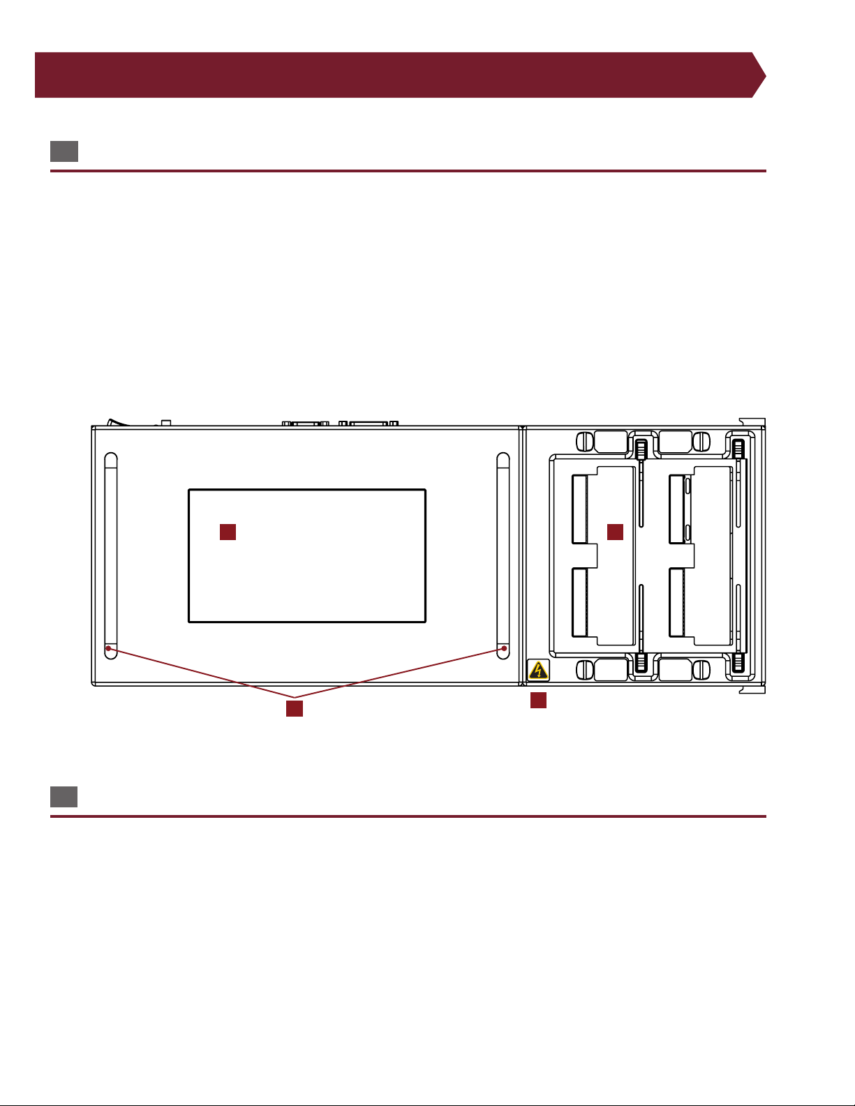
3.2 Front of Tester
a. 7" full-color graphical display with capacitive touch screen (800 x 480 pixel resolution).
b. Cirris adapter system creates an easy xturing setup system.
c. High voltage warning symbol
d. Handles for portability
c
8
Cirris 4200 Series User Manual
Page 9
a b c d e f g h i
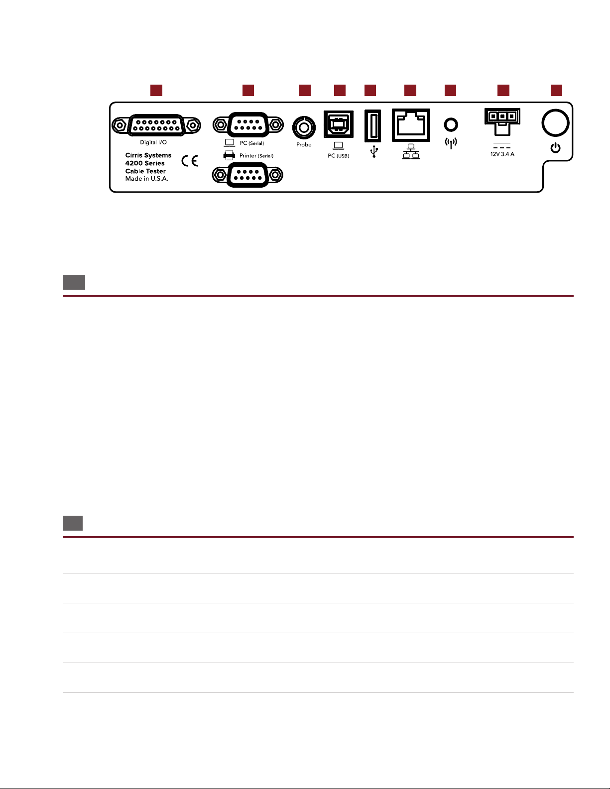
3.3. Top of Tester
a. Digital I/O: Build automation into your test process.
b. Serial ports: Connect a PC and label printer directly to your tester.
c. Probe: Attach the probe for troublshooting and diagnosing failures.
d. PC (USB): Connect your tester to a computer to access test programs and other information.
e. USB port: Use a ash drive to back up test programs and other information.
f. Ethernet: Use an ethernet cable to connect your tester for network printing and back up.
g. Antenna: (Beta) Connect wirelessly to network printers and back up.
h. Power Cord: Attach the power cord.
i. Power button: Turns tester on and o.
3.4 Setting up the Tester
■ Set Up Test Hardware
1. Connect the power cord to your tester.
2. Plug the power cord into a grounded outlet (surge protector recommended).
3. Connect the probe.
4. Press the power button to turn on the tester.
5. The tester will perform a system diagnostic (see page 41).
Hardware Setup
9
Page 10
6. After startup, the tester may require that you set the date and time for your area.
7. The Main Menu screen will open.
■ Set Date and Time
Setting the date and time ensures the correct information will show on test reports.
1. From the Main Menu, press System Settings.
2. The date and time are displayed on the buttons so you will be able to see if they need correcting. Press the button to
change the information.
3. Press the button for the eld you wish to change. For example, if you wish to change the month, press the month
button and select the correct number.
4. You can also select how you want the date and time displayed by pressing the drop down inside the date or time menu
and selecting an option from the list.
5. Once nished, press the OK button to save the changes.
6. Press Done to return to the Main Menu.
■ Set Mains Frequency
Also known as Power Line Frequency, you will want to set this value to 50 or 60 Hz depending on your country’s AC line
frequency. The correct selection will improve test measurement accuracy.
1. From the Main Menu, press System Settings.
2. Press the Mains Frequency button to switch it to either 50 or 60 Hz.
3. Press Done to return to the Main Menu.
Note: For more setup options, such as changing the language or volume, see System Settings onpage 41.
3.5 Install Expansion Boxes
Each expansion box adds an additional 128 test points. You can connect up to seven expansion boxes for a total of 1024 test
points.
1. Remove both cover plates by removing all four fasteners. Use either a screwdriver or a quarter to turn the fasteners to a
horizontal position.
2. Remove the scanner assembly and place it face down next to the tester.
3. Use a at object to press against the rivets on the inside of the chassis, detaching the plastic cover piece.
4. Replace the scanner assembly, ensuring the ribbon cable connector is accessible through the opening in the side of the
chassis.
5. Connect the ribbon cable connector from the expansion box to the main unit and push the two units together.
Note: Small posts on the expansion box will t into corresponding holes in the main unit.
10
Cirris 4200 Series User Manual
Page 11

6. Secure the expansion box to the main unit using the side latches on both sides of the tester and re-attach the cover
plates.
7. Space is available on the cover plate of each expansion box to write the adapter position. You may also consider using
removable stickers for this purpose. For example, you could continue the number system and label each adapter
position as J5, J6, J7, etc.
If you are attaching more than one expansion box, repeat the procedure. If your system uses all seven expansion boxes, you
will need to purchase a second cable. Contact your account manager at Cirris for more information and to purchase this
cable.
Hardware Setup
11
Page 12

4. Installing Adapters/Fixturing
4.1 Installing Adapters
The 420 Series uses interchangeable adapters that connect the DUT to the tester. Cirris sells a variety of adapters that mate
to standard connectors. We can also create custom adapters for less common connectors. Visit cirris.com to learn more.
1. Push the slidelocks to the outward positions.
2. Set an adapter in one or more of the J1-J4 slots. With a rm but gentle force, push the adapter forward (toward the
tester’s screen). You may have to use more pressure than expected to move the adapter completely into position. Be
careful not to bend any pins as you slide the adapter into place.
Note: Larger sized adapters can take one, two, or four positions at once. For example, a connector could use both the J-1
and J-2 positions. An adapter in this position will register in the software as a J1 adapter.
3. Once the adapter is rmly connected, move the slidelocks to the inward position to hold the adapter in place.
4.2 Fixturing
Sometimes cables are built with connectors that cannot attach directly to the tester. For this reason, xturing must be built
to provide a way to connect the device-under-test (DUT) to the adapters in the tester.
Fixturing refers to the interface between the DUT and the tester. Fixturing can be a signicant portion of the investment
in a test system. Good xturing is an essential part of ensuring the accuracy of test results and maximizes the test station’s
throughput. This means xturing needs to be at least as good, if not better than the quality of your DUT. Remember, you
want to test the DUT, not the xturing.
Cirris makes generic mating cables with one end that connects to the tester while the other end has unterminated wires.
These cables save time by completing part of the work of creating xturing cables. To learn more, visit cirris.com or contact
your account manager.
4.3 Mating Cycles
The quality of parts you use to build xturing will aect the life of your xturing. Each time a connector is attached and
removed from a xturing adapter is called a mating cycle. A connector can only take so many mating cycles before it no
longer functions like it is supposed to.
Lower quality connectors (typically with tin plating) may be rated for as few as 10 to 50 cycles, while more expensive
connectors (typically with gold plating) are often rated for 500 cycles. These ocial ratings, however, specify how many
mating cycles you can expect to endure while still maintaining the specied contact resistance in the connector datasheet.
In practice, these connectors can endure far more mating cycles and still perform adequately for test measurements.
If you are focused on having very precise resistance measurements in your testing, you will want to carefully consider the
materials you use for xturing, and maintain a maintenance schedule to ensure connectors are replaced before they cause
errors in your resistance measurements.
12
Cirris 4200 Series User Manual
Page 13

5. Cirris Hub Software
Before continuing with the tester setup, it is recommended that you install Cirris Hub Software onto a network PC.
Cirris Hub Software allows you to do the following:
● File Sharing: Share test programs among networked testers.
● File editing: Edit a test program in the software which allows networed testers to access these changes.
● Network Printing: Print all test reports from any printer connected to the network with Cirris Hub Software.
● Server Conguration: Select where you want your les stored and organized on your system.
● Tester Organization: Give names to testers and dene their printers.
A free version of the software is found on the USB ash drive that came with your tester. For installation instructions, see the
Cirris Hub Software Installation Guide.
Cirris Hub Software
13
Page 14
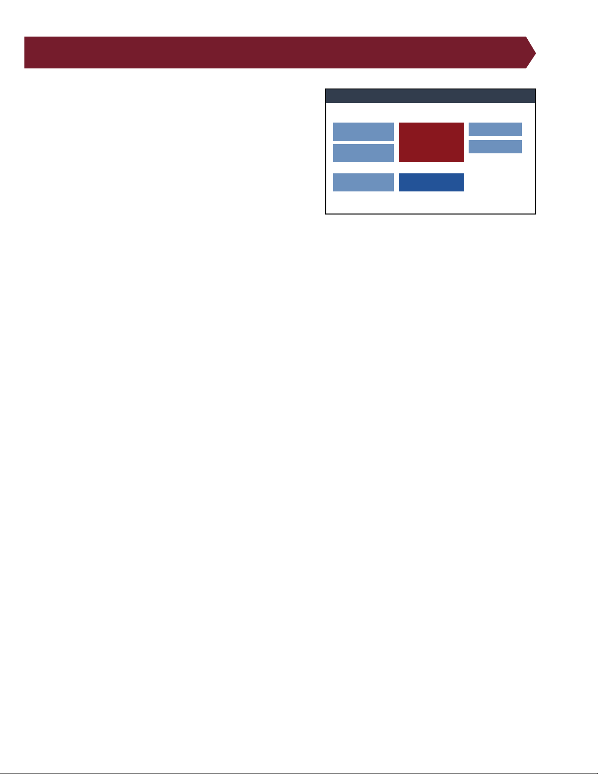
6. Main Menu
Cirris Tester
Edit
View
Create
New
Manage Files
System Settings
Loaded Test: NewTest
Signature: XXXXXX-00000
Cirris 4250 Tester | SN: XXXXXXXX Cirris OS v 0.0.0.0 | Hardware v XXXXX.1.A
Load
Test
From the software’s Main Menu, you can access other areas of the
software such as the test screen, edit test screen, and other menus.
● Loaded Test: Displays the name of the currently loaded test
program.
● Signature: Displays the loaded test’s signature. Tests that
are imported from other Cirris testers will show the same
signature as displayed on those testers.
● Edit: Change settings for a loaded test program.
● View: View details of a loaded test program.
● Test: Perform a test using the loaded test program.
● Create New: Create a new test program.
● Load: Load an existing test program to edit, view, or test.
● Manage Files: Copy, move, or delete test programs and les.
● System Settings: Perform a variety of tasks related to the setup and maintenance of the tester software including
changing volume, date, time, etc.
14
Cirris 4200 Series User Manual
Page 15
7. Create a New Test Program
Create New Test
Cancel
Edit Learn
Settings
Learn
Attached Device
Preferences
Low Voltage Start: Start Button
High Voltage Start: Start Button
Intermittents Test: For Duration
Intermittents Test Duration: 2 S
External Start Switch: OFF
External Safety Switch: OFF
Error Location: ON
Low Voltage
Connection Resistance: 5 ohm
LV Insulation Resistance: 100 k ohm
High Voltage (Hipot)
AC Frequency: 60 Hz
Cycles: 1 Cycle
Learn Settings
Edit Learn Settings
OK
Cancel
Preferences
Low Voltage
High Voltage (Hipot)
Reports
Digital I/O
Components
Test Settings
Preferences
Low Voltage Start: Start Button
High Voltage Start: Start Button
Intermittents Test: For Duration
Intermittents Test Duration: 2 S
External Start Switch: OFF
External Safety Switch: OFF
Error Location: ON
Low Voltage
Connection Resistance: 5 ohm
LV Insulation Resistance: 100 k ohm
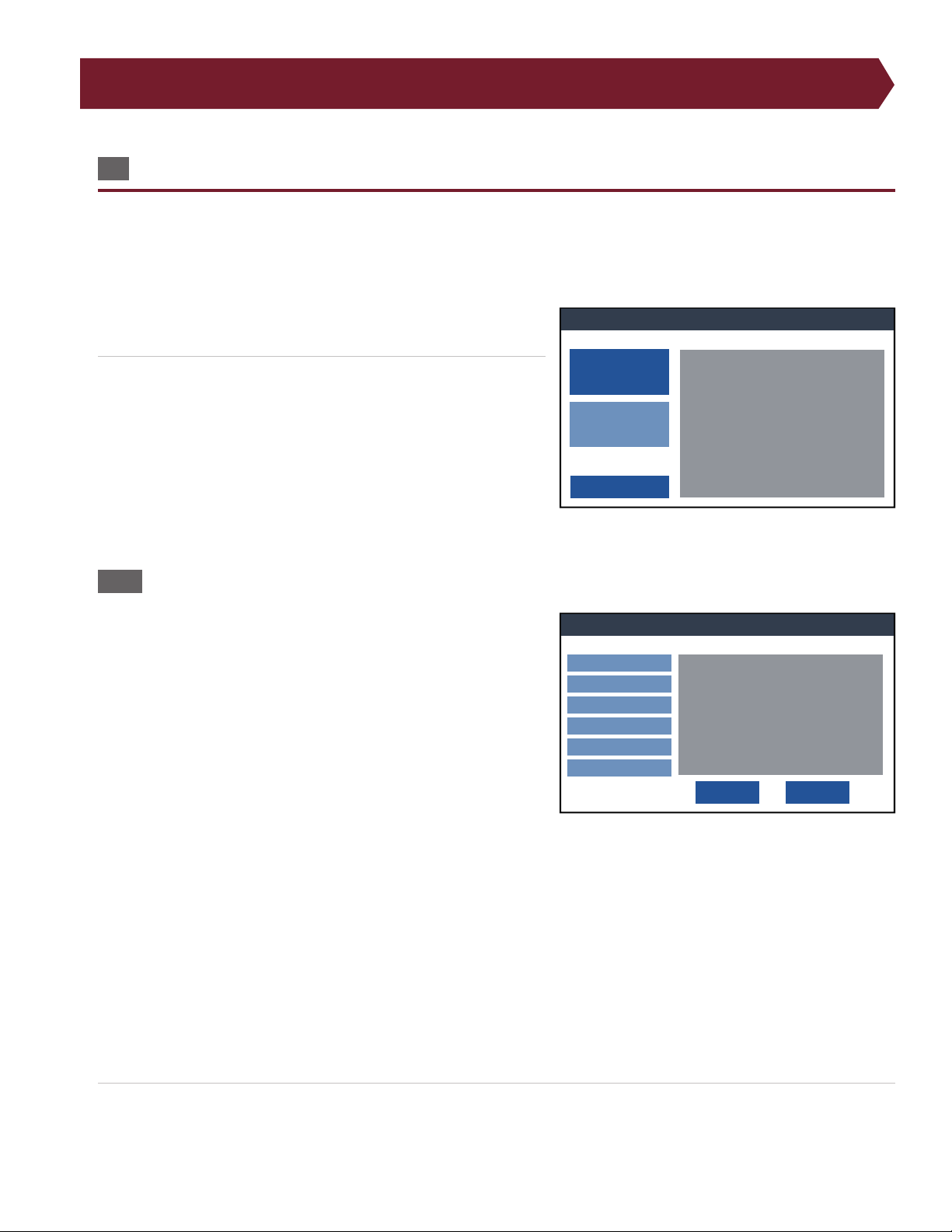
7.1 Create a New Test Program
A test program must be created before testing a cable. This is done by attaching a known-good sample cable to the
tester, adjusting the test settings, and performing a Learn. The tester will create a list of test instructions based on the
specied settings and the sample cable. Cables will then be tested using the instructions created during the learn.
1. Attach the xturing (page 12) and sample cable to the tester.
From the Main Menu, press Create New.
2. The summaries on the right side of the screen describe the
current test program settings. Press Edit Learn Settings to
adjust the settings per the sample cable specications (voltage,
components, etc.).
Note: Test settings for a new program are based on the settings of
the last test created.
7.1.1 Edit Learn Settings
Press Edit Learn Settings and use the options on the left to adjust the
settings for the new test program. These settings can be adjusted
later by selecting Edit from the Main Menu with the exception of
components.
● Test Preferences page 16
● Low Voltage page 18
● High Voltage (4250 only) page 20
● Reports page 23
● Digital I/O page 26
● *Components (New test only) page 28
● Data Collection page 29
*Components can only be edited when creating a new test program and cannot be altered after a test program has been
Learned, except by using a text editor on a computer.
Note: The next time you open Edit Learn Settings for a new test program, the last input settings will be applied to the test
program.
When you have nished adjusting the required test settings, press Save to return to the Learn menu.
3.
Create a New Test Program
15
Page 16
8. Test Preferences
Preferences
OK
Cancel
Start Button
Auto Start Delay:
1 S
Enter Lot ID: Off
Error Location:
ON
External Safety Switch:
OFF
External Start Switch:
OFF
High Voltage Start
For Duration
Intermittents Test Duration:
2 S
Intermittents Test
Cable Attached
Low Voltage Start:
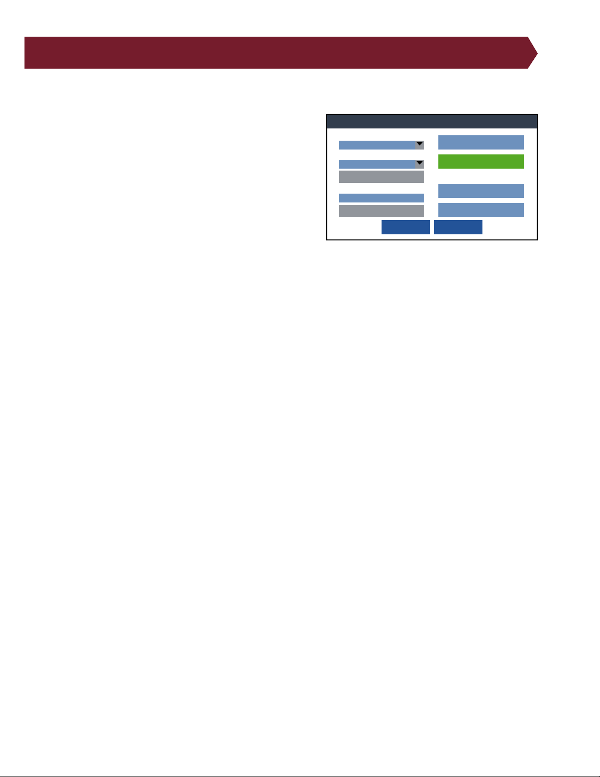
Specify which method you would like to use to begin each test.
■ Low Voltage Start
● Start Button: The test begins when Start Test is pressed or an
external switch is triggered with Digital I/O.
● Cable Attached: Test will begin automatically when a device
is connected to the tester. This condition is generally used for
testing a high volume of simple cables because it eliminates
the time it takes to push buttons on the tester screen to start
each test. However, with this start condition one of the following actions is required for a bad cable:
○ Press Finish Test: If the device contains an error, the low
voltage test will not complete until you press the Finish Test
button. The screen will update the failed test tally.
○ Remove cable: If the device contains an error and you remove the device before pressing the Finish Test button,
the test will be aborted with no record of the test.
■ High Voltage Start – 4250 only:
● Start Button: The high voltage test will begin when the operator presses Start Test or when an external switch is
triggered with Digital I/O. This lets the operator choose when the high voltage test starts.
● Auto Start: The high voltage test will automatically start after a slight delay. The delay is used to allow operators
sucient time to ensure their hands are free of the tester before the high voltage test begins.
■ Intermittents Test
An intermittents test repeatedly performs a low voltage test to give the operator time to catch problems that might only
occur intermittently. The operator can ex the cable to catch intermittent failures such as loose connections.
● OFF: No intermittents test is performed.
● Press to Stop: The intermittents test continues until the operator presses the End Test button.
● For Duration: The intermittent test continues for a predetermined amount of time. Test duration can last up to 120
seconds.
■ Enter Lot ID:
A Lot ID is a unique ID of your choosing for a group or batch of cables. The ID can appear on reports to help you keep
track of dierent batches of cables.
● ON: When this setting is enabled, the user must enter a Lot ID before the test window will open.
● OFF: No Lot ID is required before testing and won’t appear on reports.
16
Cirris 4200 Series User Manual
Page 17

■ External Start Switch:
External Switch allows the tester’s digital I/O port to receive an input signal from an external switch to start a test. Use Pin
1 on the digital I/O connector for the external start switch.The external switch can be a foot pedal or a button.
● ON: The tester starts a test from the external switch signal.
● OFF: The tester does not look for the external switch signal.
Note: Turning “External Switch” on does not inhibit your ability to press START TEST on the tester display.
■ External Safety Swtich:
Safety Switch requires that the tester sees a high signal on pin 2 of the digital I/O connector before starting the hipot test.
Safety Switch can be used to help ensure an operator does not shock themselves during a hipot test. Safety Switches can
be dual palm switches wired in series, a foot pedal, or a sensor in automated test equipment.
● ON: The tester will look for a high signal on pin 2 of the digital I/O connector before starting a hipot test.
● OFF: The tester ignores the signal status of input pin 2 on the digital I/O connector.
Note: For more information on Digital I/O, see page 26.
Test Preferences
17
Page 18
9. Low Voltage
Edit Low Voltage Settings
Connection Resistance:
5 ohm
Measured connection resistance below this value passes
the low voltage test.
Measured insulation resistance above this value passes
the low voltage test.
LV Insulation Resistance:
100 k ohm
OK Cancel
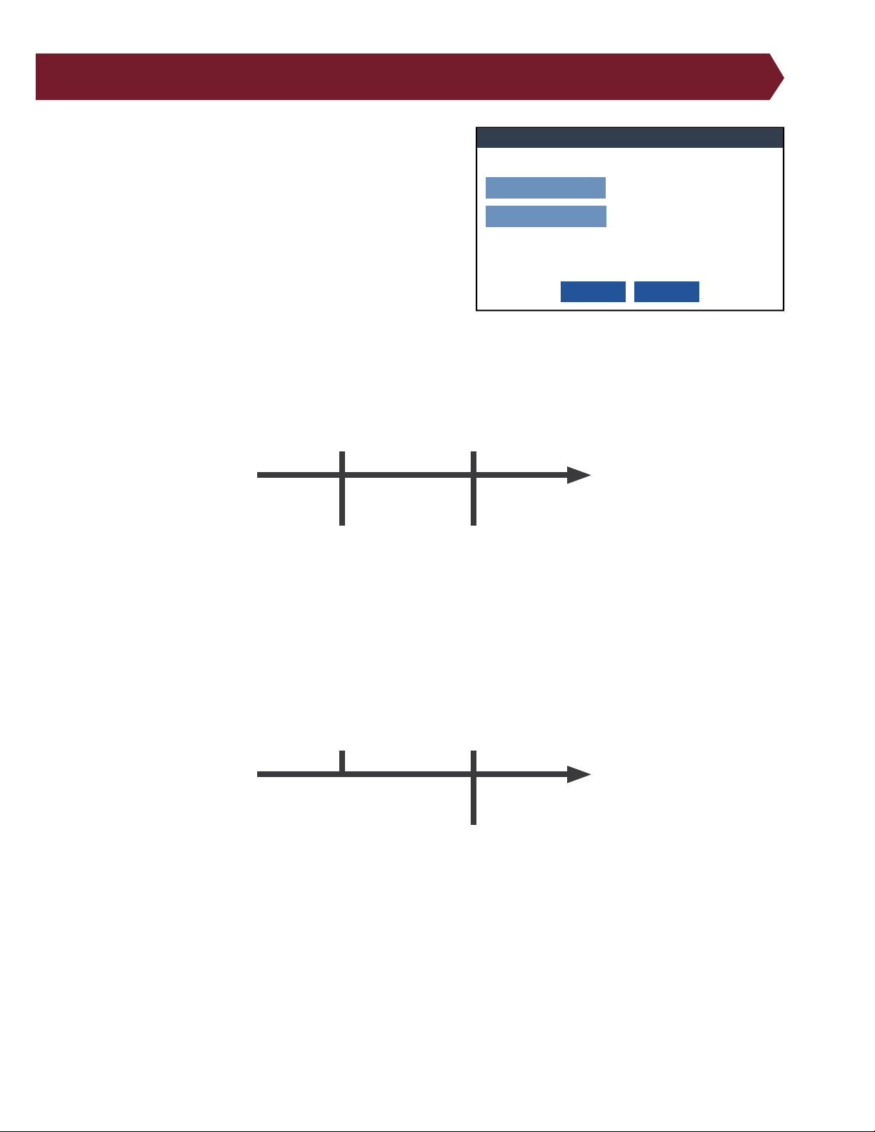
A low voltage test checks for shorts, opens, and other basic errors.
The following settings control how the low voltage test is performed:
■ Connection Resistance: This setting determines if the
device passes or fails based resistance settingsi.e. connections with
resistances measured above this value will fail.
● Range: 0.1 ohm – 5.0 M ohm
● As shown in the graphic below, expected connections—con-
nections measured below or equal to the connection resistance value—will pass while any measurement above this
value will fail. A resistance measured above the connection
resistance value, but below the LV insulation resistance value,
will be reported as a high resistance error. A measurement above the LV Insulation Resistance Value will be reported
as an open error.
0.0 Ω
Good
Connection
Resistance
High Resistance
LV Insulation
Resistance
∞Ω
Opens
■ LV Insulation Resistance: Intended connections above the LV insulation resistance value are considered open
during a low-voltage test (and ignored during a Learn).
● Range: 0.1 ohm – 5.0 M ohm
● As shown in the graphic below, during a shorts test (checking for unintended connections), resistance measure-
ments above the LV insulation resistance value will pass. Any connections detected below this value will be reported
as a short error.
Connection
Resistance
0.0 Ω
Shorts
LV Insulation
Resistance
∞Ω
Good
18
Cirris 4200 Series User Manual
Page 19
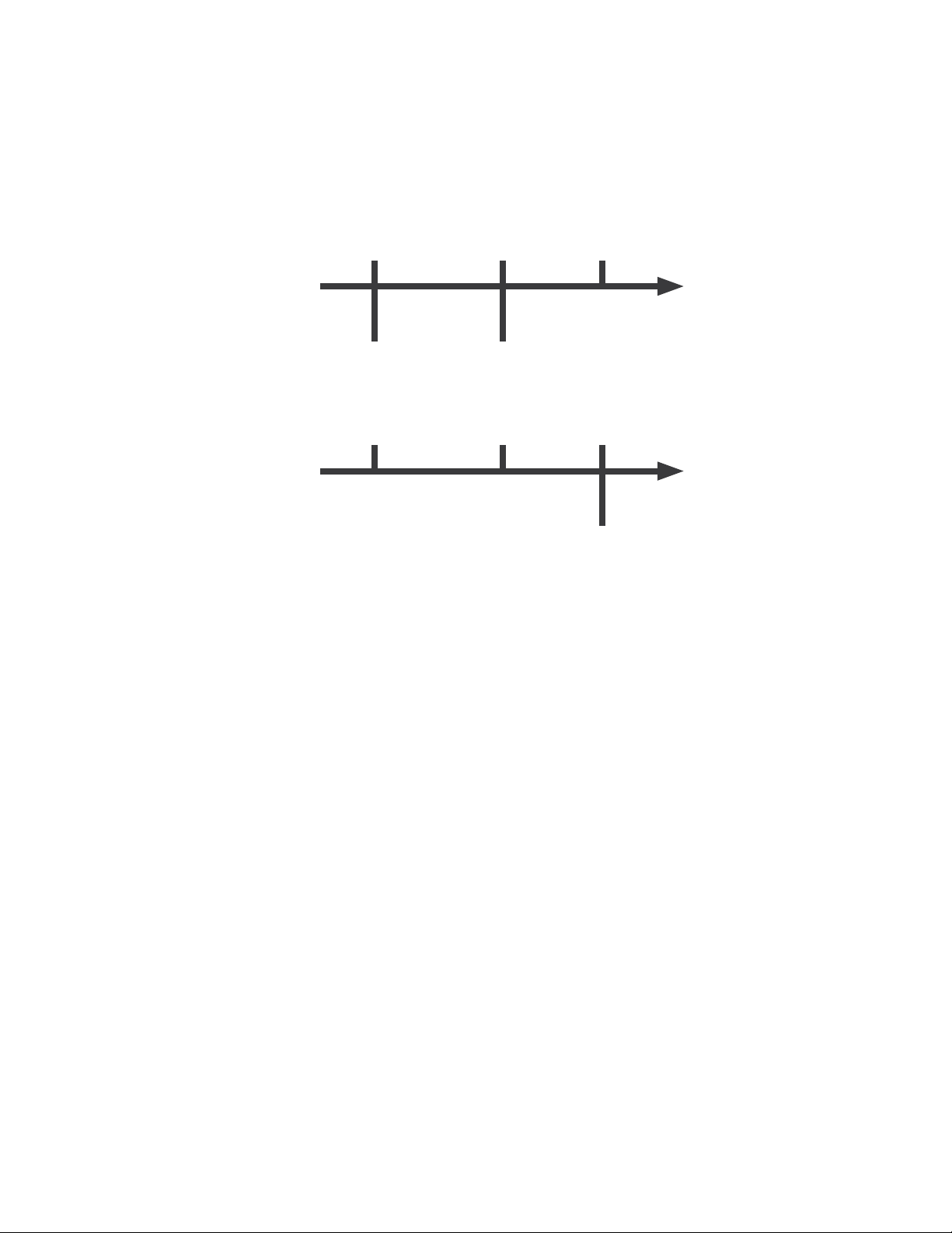
■ Component Resistance: (This value is only used when there are components in the test.) This value is auto-set
during the Learn process, and should be 5-25% less than the lowest component found in the device being tested.
● Range: 0.1 ohm – 5.0 M ohm
● The following graphic shows how component LV settings dene errors for intended connections if there are com-
ponents in the test. This value has no impact on whether an intended connection passes or fails, but does inuence
whether a failing connection is labeled as High Resistance or Open.
Connection
Resistance
0.0 Ω
Good
● As shown in the graphic below, the Component Resistance value has no impact on the shorts test.
Connection
Resistance
High Resistance
0.0 Ω
Component
Resistance
Component
Resistance
Shorts
LV Insulation
Resistance
∞Ω
Opens
LV Insulation
Resistance
∞Ω
Ignored
Low Voltage
19
Page 20
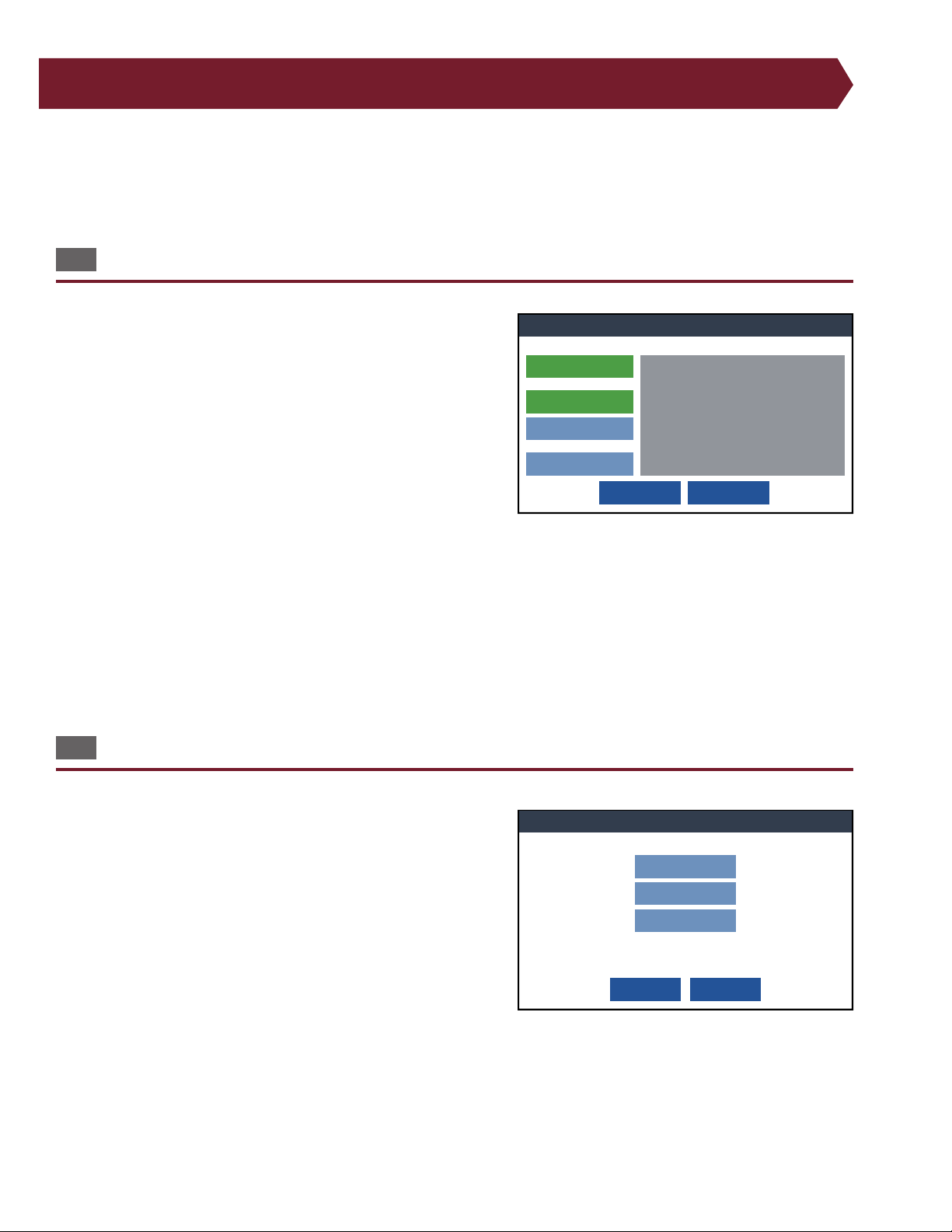
10. High Voltage (Hipot) - 4250 only
Edit High Voltage Settings
OK Cancel
High Voltage: ON
Hipot Settings
Basic Settings
Advanced Settings
Options
AC Frequency: 60 Hz
Cycles: 1 Cycle
DW Voltage: 50 V
DW Max Current: 0.1 mA
DW Dwell Time: 10 mS
IR Voltage: 50 V
IR Minimum Resistance: 5 M ohm
IR Dwell Time: 2 mS
Soak Until GOod: ON
IR Max Soak Time: 0 S
Apply High Voltage To: All Adapter pins
Basic Settings
OK Cancel
High Voltage:
300V
Insulation Resistance:
10 M ohm
Dwell Time:
100 mS
High voltage or “hipot” testing is used to nd defects and contaminants that could cause the cable to fail.
WARNING: Read the Safety/Support section of this manual (page 4) before performing high voltage testing. For more
ideas on high voltage safety, visit cirris.com/safety.
10.1 High Voltage Testing
High voltage settings can only be edited when high voltage is turned
ON.
● ON: The tester will perform a high voltage test after a success-
ful low voltage test.
● OFF: The tester will not perform a high voltage test.
● Basic Settings: Adjust the basic high voltage settings you
might nd in your test specications, such as voltage, insulation resistance, and dwell time. Other settings are automatically set accordingly.
● Advanced Settings: Adjust individual settings for the Dielec-
tric Withstand (DW) test and the Insulation Ressitance (IR) Test.
Note: Once Basic Settings or Advanced Settings have been changed, the button will turn green while the other button will
turn blue.
● Options: Adjust other settings having to do with the high voltage test such as selecting which pins will be included
in the test, whether a high-cap shield is present on the cable, and if you want to use high-speed mode.
10.2 Basic Settings
High Voltage: Set the voltage limits required for your cable’s
specications.
Insulation Resistance: Set the resistance limits in order to measure
your cable’s isolation. The measured insulation resistance must be
equal or greater to the insulation resistance setting for the test.
Dwell Time: Set the amount of time the IR value must remain good
to pass the test. The reported resistance value for the IR test is an
average of the measurements taken over this time.
20
Cirris 4200 Series User Manual
Page 21
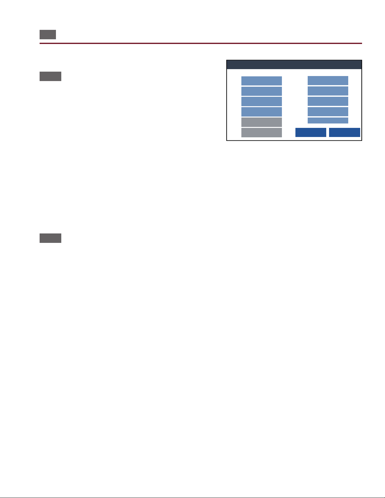
10.3 Advanced Settings
Advanced Settings
OK Cancel
DW Voltage:
300 V
DW Max Current:
0.1 mA
DW Dwell Time:
100 mS
DW Mode:
DC
AC Frequency:
60 Hz
IR Voltage:
300 V
IR Minimum Resistance:
10 M ohm
IR Dwell Time:
2 mS
IR Soak Time:
0 S
Soak Until Good: OFF
Insulation Resistance (IR) TestDielectric Withstand (DW) Test
Cycles:
1 Cycle
10.3.1 Dielectric Withstand Test
In a Dielectric Withstand (DW) Test, a voltage much higher than
the normal operating voltage is applied between points on the
device-under-test. This ensures the wire insulation can withstand a
higher amount of voltage (such as a surge) without failing. This test
will also nd near shorts, such as those caused by surface contaminants on connectors or wires that are almost touching.
DW Voltage: The amount of voltage used for DW test.
● Range: 50 V – 15000 V
DW Max Current: The maximum current level allowed during DW test.
● Range: 0.10 m – 1.50 m A
DW Dwell Time: The amount of time voltage is applied.
● Range: 10 mS – 120 S
10.3.2 Insulation Resistance Test
An Insulation Resistance (IR) Test measures the overall electrical insulation resistance to ensure that it meets the specied value. For a cable to pass the IR test, the measured insulation resistance must be equal or greater than the insulation
resistance setting for the test.
IR Voltage: The amount of voltage used for an IR test.
● Range: 50 V – 1000 V
IR Minimum Resistance: Minimum resistance needed for insulation to pass the test.
● Range: 5.0 M – 1000 M ohm
IR Dwell Time: The amount of time the IR Resistance value must remain good to pass the test (this is how long the test will
run after soak time). The reported resistance value for the IR test is an average of the measurements taken over this time.
● Range: 2 mS – 120 S
Note: Because the reported value is an average, this setting can also be used to lter out noise caused by the AC power
coming into the tester. For the highest test accuracy, use an IR dwell of at least17 mS to lter out 60 Hz noise and 20 mS to
lter out 50 Hz noise.
IR (Max) Soak Time: The amount of time that the tester applies voltage before performing the nal IR measurement. The
test can be congured to soak for a period, or until the IR test passes. This setting is useful in humid environments or when
the cable insulation has problems with dielectric absorption.
● Range: 10 mS – 120 S
Note: When an IR Max Soak Time is set, the tester continues to monitor the dielectric withstand current. If the dielectric
withstand current is exceeded, the tester reports a “Dielectric Failure”.
High Voltage (Hipot) - 4250 only
21
Page 22
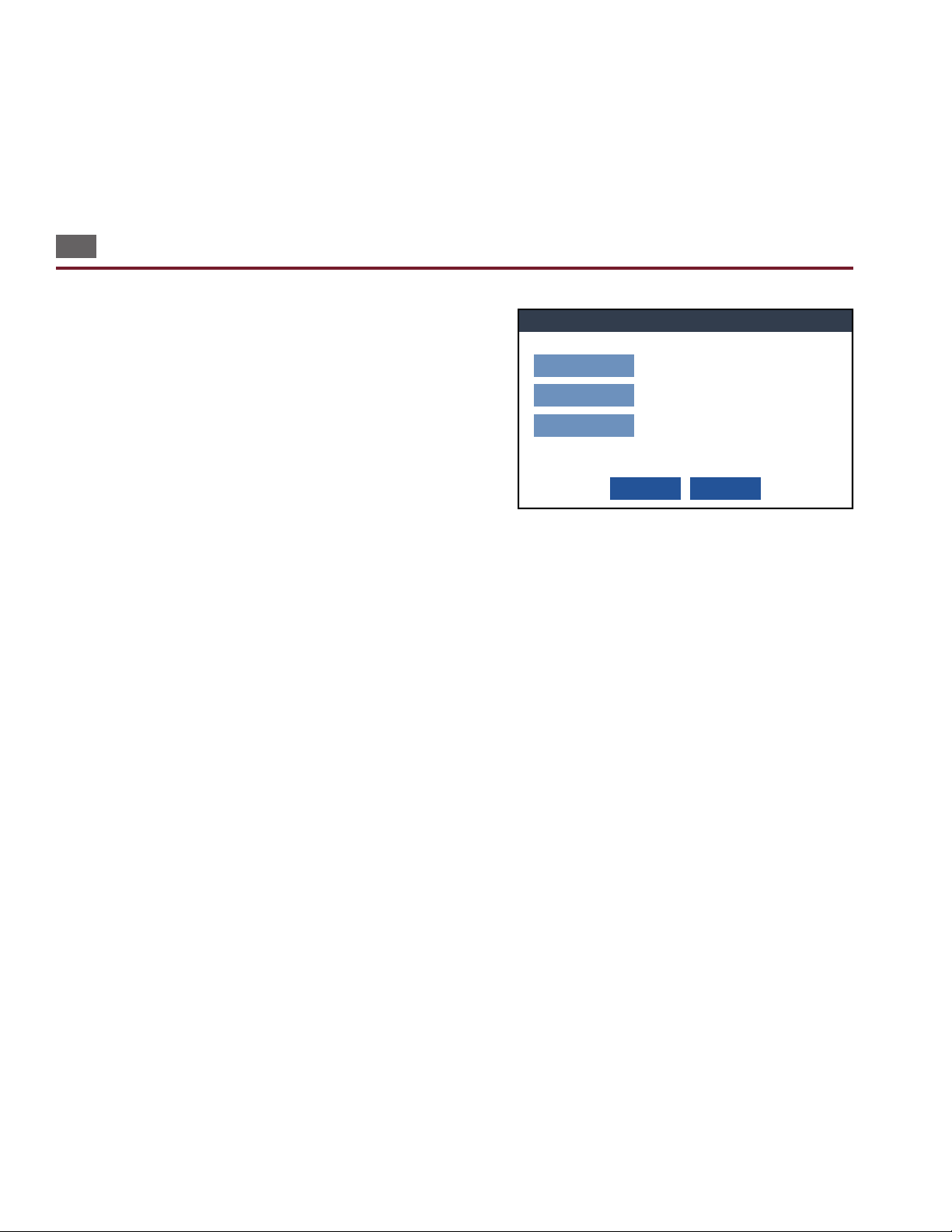
Soak Until Good: Applies a voltage to the cable until the tester measures IR values that exceed the IR minimum resistance
High Voltage Options
Apply High VOltage To:
All Adapter Pins
Allow High-Cap Shield:
NO
High-Speed Mode:
OFF
Apply high voltage to all adapter pins, or just to pins included
in nets.
Allow one highly capacitive net, such as a shield, to pass the
high voltage test.
Employ an algorithm to speed the HV Test, but still ensure
every net is tested to every other.
OK Cancel
or reaches the IR (Max) Soak Time.
● ON: Applies voltage until the tester measures IR values that exceed the IR minimum resistance (i.e. could take less
time than Max Soak Time).
● OFF: Always applies voltage for duration of IR (Max) Soak Time.
10.4 Options
■ Apply High Voltage to: This setting determines which test
points get high voltage applied to them during the high voltage test.
● All Adapter Pins: All test points in the tester interface con-
nectors will be involved in the test, regardless of whether they
have connections to other points in the test.
● Connections Only: High Voltage is applied only to test points
that have connections dened in the test program.
■ Allow High-Cap Shield: This option allows the user to
continue high voltage testing a device that would normally fail the
test due to a single over-current error. This error is presumed to be
caused by a highly capacitive shield around the device.
● YES: Test continues with a single over-current error.
● NO: Test fails when any error occurs, regardless of the cause.
Note: High Cap Shield is available to assist with highly capacitive shields, which would fail with standard high voltage
settings. By turning on the High Capacitance Shield setting you can successfully test a cable with a high capacitive shield.
■ High-Speed Mode: The HV test applies a voltage to multiple nets simultaneously while still ensuring that each net
is tested against every other net, thus speeding up the test process. If an error is found, each net is tested individually to
locate the exact net that has the error.
● ON: Tester applies HV to nets in groups for faster testing.
● OFF: Tester applies HV to each net one at a time while all other nets are pulled to ground.
WARNING! High-Speed Mode with highly capacitive devices can slow testing. Highly capacitive nets may cause overcurrent failures, meaning the nets will need to be tested individually. This could cause the test to slow down signicantly.
22
Cirris 4200 Series User Manual
Page 23
11. Reports
Reports
OK
Cancel
Add
Edit
Remove
Run Report
Reports:
Edit Report
OK
Cancel
Run Report
Edit Report Name:
<RunReport.cprn>
Change Template:
Network On End Test Run
Printer Auto Print On Event:
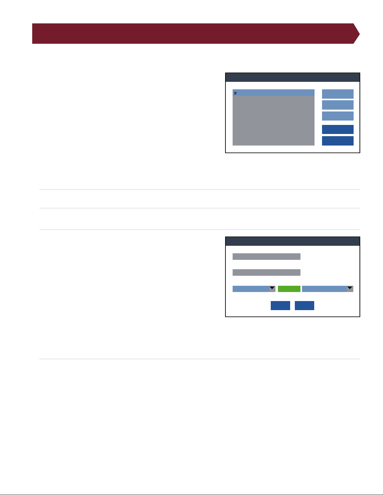
The 4200 Series testers can produce the following reports and labels:
Run Report: Each line of the Run Report shows summary and
statistical information for each DUT tested in a test run. This report
shows information on an entire test run, listing passes and failures.
Batch Test Report: Shows that all cables in a batch passed. This is the
best report to give to a customer with the tested cables.
Test Report: Prints a detailed report for a single device that passed a
test. This report can also be sent to customers.
Error Report: Prints a detailed report for a single device that failed a
test. This report is often used for rework.
Fail Label: Prints a Test Label for labeling a device after it has failed a
test.
Pass Label: Prints a Test Label for labeling a device after it has passed a test.
1. Press Add to access the list of available reports.
2. Select a report from the list and press Add.
3. Edit the report to meet your requirements. You can change the
following criteria:
● Report Name: Change the name of the report to your prefer-
ence.
● Template: Use a built-in template or a custom template de-
signed in Cirris Hub Software.
● Printer: Select which printer you would like to print the
report. You may have several network printers to choose from,
or you may select a label printer.
● Auto Print: Choose whether the report prints automatically or
the operator presses a button.
● Event: If the Auto Print option is turned on, select the event that triggers the report to print.
4. Press OK to save the Edits.
Note: If Auto Print is turned o, you will be able to select which report you want to print after testing a cable or batch of
cables. After pressing the Print button, a list of available reports will open in a window. Select which report you would like
to print and press OK.
Reports
23
Page 24

11.1 Editing Report Templates
Default templates are included with the tester. You cannot create new templates. You can only edit existing templates.
■ Labels
Default templates for pass and fail labels are included with the tester. These labels print on a 4x2 size label and include
test results, test program name, date, and time. You can also create your own labels with custom text and graphics.
To design label templates, download the free Zebra Designer V2 software. This software allows you to add tokens, images,
and other elements to the label.
● To design labels, download the free software, Zebra Designer V2.
● Add tokens, logos, and other information (see below for acceptable tokens).
● Once you have completed your label design, select the Print to File option to save the label as a .prn label le.
● Follow the steps for Reports to add the new label template to your testser.
Once you have completed your label design, print the label, selecting the Print to File option to obtain a .prn label le.
Replace the current template with the revised version.
■ Reports
Default report templates are provided by Cirris. If you would like to edit these reports, connect your tester to a PC.
Navigate to the hidden reports le (see below) and make any necessary edits to the templates in a text editor. Save the
template as a .prn le and replace the current template with the revised version.
Note: Currently, the font size and stylesuch as boldcannot be changed on reports. Capitalization can be used when
needed for emphasis. This limitation only applies to reports printed from standard page printers. Label templates
formatted using Zebra Designer V2, allow more exibility.
■ Adding Templates to the Tester
Once a template is designed with the information needed, the design can be transferred to the tester in the following
way:
1. Turn o your tester and connect it to a computer using the provided USB cable.
Note: If the tester is running, you will not be able to access it through a PC.
2. On your PC, navigate to the tester through File Explorer. When connected to a computer, the tester will show up as a
removable storage device.
3. The templates will be in the path: <4200 Series>:\~Cirris\System\Reports\
Note: This is a hidden folder. You must show hidden items to access this folder. An IT professional can help you show
hidden items.
4. Add your custom label (.prn le) to the folder.
5. With the template added to the correct folder, turn the tester on.
Page 25

6. Load a test program and press Edit Test. Navigate to Reports and either add a new report or select a report to edit (page
31).
7. Under Change Template option, select the report template you added to the tester. Press OK to and save your changes.
Note: To retrieve the original default template, delete the revised template. When you next turn on the tester, the default
template will be restored.
■ Tokens
Specic information included on the label from the tester such as test results, time, and date is written on the label in the
form of tokens. Tokens must be written in a Zebra font on the label exactly as shown below.
Available tokens include:
● {TestName}
● {Date}
● {Time}
● {ErrorDetails}
● {TestStatus}
● {TesterID}
● {TesterType}
● {LotID}
● {Adapters}
● {DeviceDescription}
● {DeviceID}
● {DeviceSignature}
● {Components}
● {Connections}
● {ErrorSignature}
● {KelvinPairs}
● {Parameters}
● {ParamSignature}
● {SpcSettings}
● {FailedCount}
● {PassedCount}
● {TotalCount}
Reports
25
Page 26
12. Digital I/O
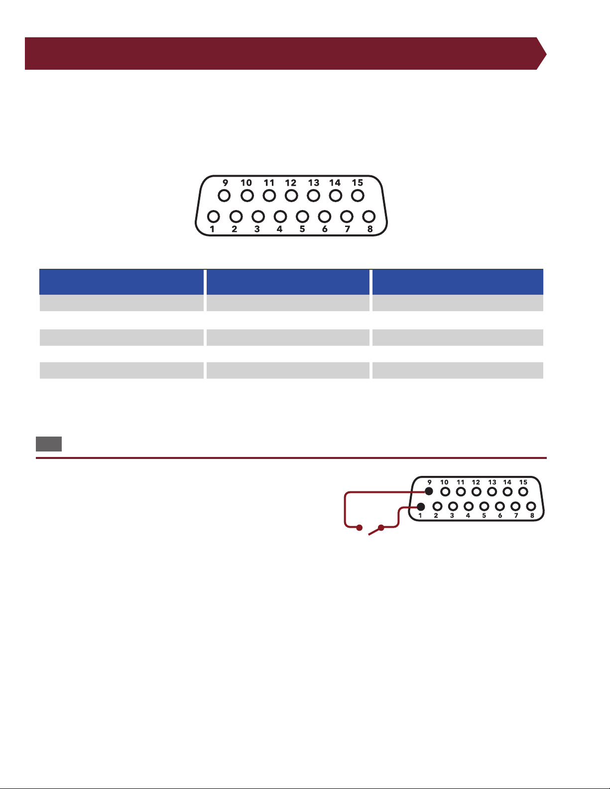
With digital I/O, the tester can start a test based on input from an external switch, such as a foot pedal. Through its outputs,
the tester can also activate devices such as LEDs.
The digital I/O port is located on the back of the tester. The pinout is as follows:
Pin Function Pin Function Pin Function
1 Input Switch LV Start 6 Output 11 Output
2 Input Switch HV Start 7 Output for good test 12 Power + 10 VDC, 100 mA max.
3 Input 8 Output for bad test 13 N/A
4 Input 9 Power + 5 VDC, 100 mA max 14 Ground
5 Output 10 Output 15 Ground
To use the External Switch input, you must set the test program’s Start Condition to Press Button.
12.1 Inputs
The 4250 tester has two inputs, pins 1 and 2. The low voltage input is
on pin 1 of the digital I/O connector. If a DC +5 volt (logic high) is applied to pin 1, the tester behaves as if START TEST were pressed. You can
use the DC +5 volt power source on the digital I/O connector to supply
the DC +5 voltages through the switch circuit. Make sure you wire your
external switch so it is normally open. Do not apply an AC voltage to
the input.
Example of Digital I/O input wired with start switch.
26
Cirris 4200 Series User Manual
Page 27
12.2 Outputs
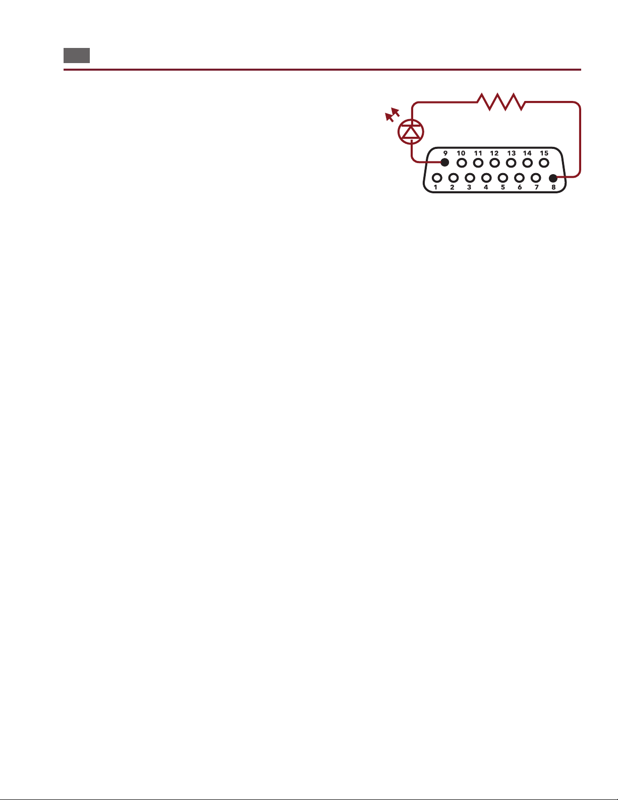
The tester’s outputs are “sinking” (open collector) outputs. When activated they will connect (or sink) to ground, in eect turning ON the output
circuit. The outputs can sink up to a nominal 24 volts at 500 milliamps.
To limit the output current, always ensure adequate resistance between
power supply and the output.
As an example, let’s say you want to light an LED to indicate a bad test.
You will want to connect the LEDs to pins 8 (output for bad test) and 9
(+5V). The LED requires only 20 mA, so we can use the +5 DC volt supply
on the digital I/O port to power the circuit. Use a resistor in series with the
LED to limit the current going through it. How do you choose the resistor?
The LED in this instance has a forward bias voltage drop of two volts; therefore, three volts must drop across the current limiting resistor. Knowing the
voltage drop is three volts across the resistor and the desired current is 20
mA, Ohms Law can be used to determine the resistor value.
V/I = R
3V/20mA = 150 Ohms
In this example, you would use a 150 Ohms resistor to limit the current through the LED.
Example of Digital I/O outout wired with LED.
When a test completes, the tester will pull the output to ground allowing current to ow in the circuit, and the LED will
turn on. If the test fails, pin 8 will be pulled low. Pin 7 will be pulled low when a test passes. These results will only activate
when all tests nish (including after the intermittents test is complete).
Digital I/O
27
Page 28
13. Components (New test program)
Edit Learn Components
OK
Cancel
Learn Resistors:
OFF
Learn Capacitors:
OFF
Learn Four-Wire:
OFF
Learn Twisted Pair:
OFF
Learn Diodes:
OFF
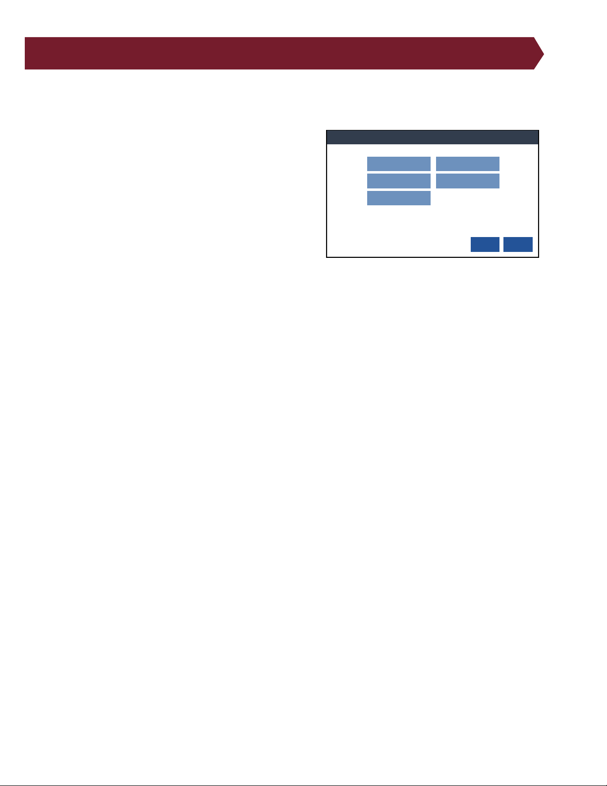
Components can be automatically added to a test program during the Learn process for a new test program. If not originally Learned, the test program can be edited wtih a text editor. The 4200 Series can Learn the following components:
● Resistors
● Capacitors
● Diodes
● Four-Wire
● Twisted Pair – 4250 only
Select the required component to add it to the test program.
● On: The component type will be Learned by the tester and
added to the test program.
● O: The test program will not include the component.
Although tolerences that are automatically set during the Learn, review the test program to verify that the measured
value of the components is the nominal vaue. One way to review the values is through a text editor such as in Cirris Hub
Software.
28
Cirris 4200 Series User Manual
Page 29
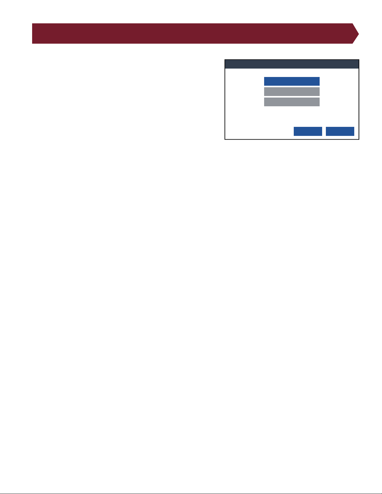
14. Edit Data Collection Settings
Edit Data Collection Settings
OK Cancel
Data Collection: OFF
Measured Values: OFF
Error Text: OFF
When turned ON, Data Collection allows you to store important
information.
The following data elements are always stored:
● Run Number
● Analyzer Serial number
● Cable Description (if dened)
● Cable File Name
● Operator Name (if dened)
● Date and time tested
Data Collection:
● Total Tested
● Total Good
● Total Bad
● Error Types Summary
● Custom, per group (if stored in Scripting)
● Custom, per Cable (if stored in Scripting)
Measured Values:
● Net or Instruction Label
● Net or Instruction Measurement
Error Text:
● Error Number
● Error Code
● Error Type
● Error Text
The data is stored in the le [tester serial number].c_d and can be accessed through a text editor or SPC Link included
in the SPC Data Collection software from Cirris. Use a USB cable, ash drive, or network cable to open the folder on a PC.
Instructions are included with the software. Once imported into SPC Data Collection, the le is deleted.
Edit Data Collection Settings
29
Page 30
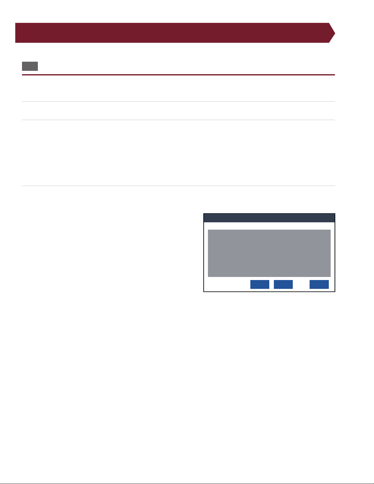
15. Perform a Learn
Verify and Save Learned Test Program
Cancel
Learned Test Program
(A93484-00000
J1 03FAC1
J2 03FAC1
CONNECTION RESIS 10.0 ohm
LV INSULATION RESIS 100 K ohm
DWV VOLTAGE 300 V
DWV MAX CURRENT .1mA
INSULATION VOLTAGE 300 v
INSULATION RESIS 10.0 M ohm
C:\NewTest.wir
Save
Save As...
15.1 Perform a Learn
The 4200 Series tester creates test programs by scanning a cable and forming a list of instructions based on the cable and
test settings.
1. From the Main Menu, press Learn New Test to reach the Create New Test screen.
2. After editing the Learn settings, make sure the cable is attached and press Learn Attached Device. The tester will scan
the attached cable and create a test program.
Note: If there were any errors during the Learn, you will be alerted with a Learn Failed notication. Check the Learn/Test
settings for errors. Also check the cable that was used during the Learn. Once you have made adjustments to either the
settings or the cable, press Learn Attached Device once more. If the Learn fails again, repeat this process to nd the cause
of the failure.
3. In the Learned Test Program window, verify the test instructions match the required specications.
If the test program is correct, select one of the following options:
● Save: By pressing Save, the tester will name the test program
“NewTest.wir” and will store it in a default location. The next
time a Learn is performed, selecting Save will overwrite the
test program saved in the default location.
If you save the test location in the default location, the test program
will be overwritten the next time you press Save when creating a new
test program.
● Save As...: By pressing Save As, you will be able to select a storage
location and name for the test program.
a. Navigate to a location within the directory to save the test
program. If you are using Cirris Hub Software, you can
choose a location on the network. This will allow other networked testers to use the test program as well.
b. To name the new test program, select New... Type in a name and press Done.
Once you have selected a location, you will be brought to the same location where the test was saved the next time you save or load a
test.
● Cancel: Return to the Learn screen without saving.
If the test program is not correct, press Cancel to return to the Learn menu. From there you can adjust the test settings
and perform a new Learn.
30
Cirris 4200 Series User Manual
Page 31
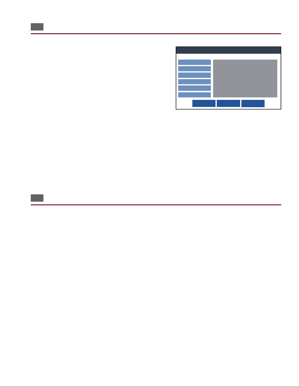
15.2 Edit a Test Program
Edit Test Settings
Save Save As ... Cancel
Preferences
Reports
Data Collection
High Voltage (Hipot)
Low Voltage
Digital I/O
Test Settings
Loaded Test: NewTest
Preferences
Low Voltage Start: Start Button
High Voltage Start: Start Button
Intermittents Test: For Duration
Intermittents Test Duration: 2 S
External Start Switch: OFF
External Safety Switch: OFF
Error Location: ON
Low Voltage
Connection Resistance: 5 ohm
LV Insulation Resistance: 100 k ohm
Load an existing test program and select Edit. The options allowed
for revision are the same as those explained in their sections. Alter
the specications for the Test Program, including:
● Test Preferences
● Reports
● High Voltage (Hipot) – 4250 only
● Low Voltage
● Digital I/O
Components cannot be revised at this point on the tester. If you need
to revise components, you can edit a test program using a text editor on a computer. One way to do this is using Cirris
Hub Software (see page 13).
After revising a test, you have the option to Save, Save As, or Cancel the changes.
● Save: Saves the test program with a default name and location and returns to the main menu.
● Save As: Allows you to choose a name and location for the test program.
● Cancel: Return to the previous screen without saving.
15.3 Edit Test Programs on a PC
Test programs can be edited on a PC using a text editor.
1. Using the provided USB cable, connect the tester to a PC. Make sure the tester is turned o.
2. Connected to a computer, the tester will behave like a ash drive. In File Explorer, navigate to the tester labelled 4200
SERIES.
3. Test Programs are visible inside the tester le. Open the test program in a text editor such as Notepad.
4. You can edit the test name, change point labels, modify component test values and links, and add components.
5. Save the le and close the program.
6. After editing the test program, turn on the tester. Load the edited test program. From the Main Menu press View to see
the changes to the test program.
Perform a Learn
31
Page 32

15.3.1 Edit Point Labels
Create labels for points using a text editor.
1. Open the test program in a text editor.
2. Beneath the test program, create a LABELS header.
3. Under the header, type the original point name and the new point name, as shown in the example.
LABELS
J1-001 = Point_01
J1-002 = Point_02
J1-003 = Point_03
J1-004 = Point_04
J1-005 = Point_05
J1-006 = Point_06
J1-007 = Point_07
J1-008 = Point_08
J1-009 = Point_09
J1-010 = Point_10
J1-011 = Point_11
4. Save the le and close the program.
5. Turn on the tester. Load the edited test program. From the Main Menu press View to see the changes to the test
program.
32
Cirris 4200 Series User Manual
Page 33
16. Run a Test
Ready to Test
Not Tested
Start Test
Abort
Print
Done
Lot:
Passed: 0, Failed: 0
Total: 0
Test: NewTest
The tester performs three tests in the following order:
● Low Voltage Test: Tests for continuity and basic isolation.
● High Voltage Test – 4250 only: Tests for thorough isolation.
● Intermittents Test: Tests for intermittent errors that could arise while the cable is being moved.
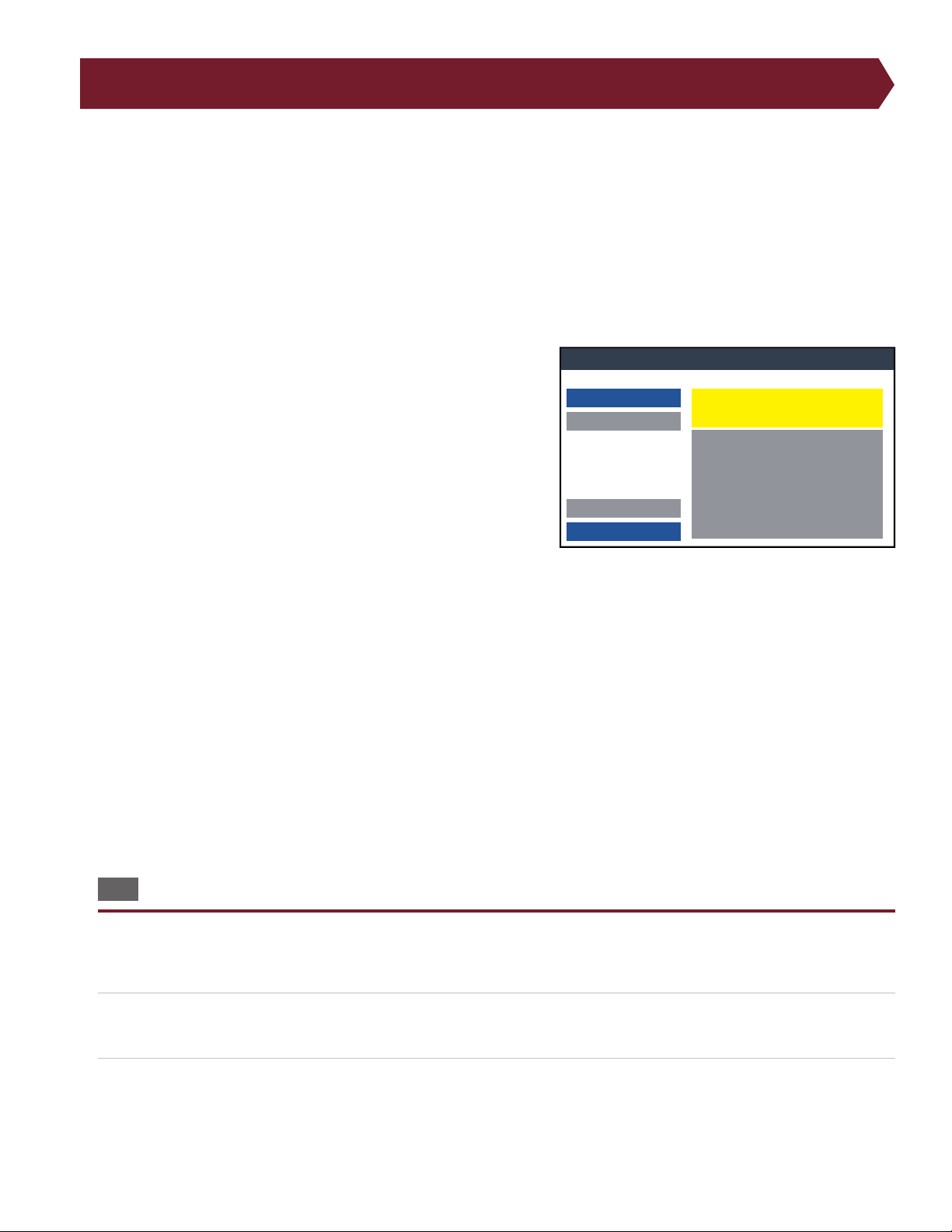
■ Test Window Overview
The test window displays user instructions, test results, and other information.
User Instruction/Test Status: The box at the top of the screen
displays instructions for the user or shows the status of the tester.
Test name: The name given when the test program was created will
display here.
Start Test button: This button is active when the Start Condition is
set to Start Button.
Abort button: Ends test at any point. The aborted test will not be
recorded as though it were never tested.
Lot: The Lot ID will act as an identier to the batch of cables being
tested. If turned o, the space next to Lot ID will be left empty.
Good/Bad/Total: Tracks number of cables tested including how many cables passed and failed.
Print: Press button to print test results if a report was selected for the test.
Test Results: This box will display one of three statuses:
● Not Tested
● Passed
● Failed
Result Details: Passes, fails, and error details from each test (Low Voltage, High Voltage, Intermittent) will appear in this
window including error details.
16.1 Perform a Test
1. From the Main Menu, verify the required test program is loaded (the name of the test program is found at the top of the
main menu screen) and then press Test.
2. If Lot ID is turned on, you may be prompted to enter an identifying series of numbers or letters. The Lot ID will be used
to identify the batch of cables being tested. For more information on Lot ID, see page 27.
3. Depending on the chosen Start Condition, attach a cable or press Start. (The bar at the top of the window will prompt
which action to take.)
Run a Test
33
Page 34
16.1.1 Low Voltage Test
Testing...
Not Tested
Start Test
Abort
Print
Done
Lot:
Passed: 0, Failed: 0
Total: 0
Test: NewTest
Testing High Voltage...
Not Tested
Start Test
Abort
Print
Done
Lot:
Passed: 0, Failed: 0
Total: 0
Test: NewTest
High Voltage (Hipot) Test
** Caution - High Voltage **
Start Test Abort
Testing for Intermittents...4
Not Tested
Start Test
Abort
Print
Done
Lot:
Passed: 0, Failed: 0
Total: 0
Low Voltage Test: Passed
High Voltage Test: Passed
Test: NewTest
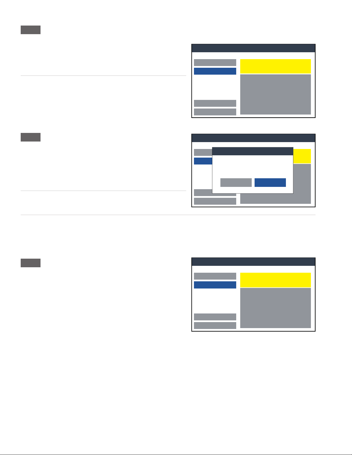
4. The tester will perform a low voltage test, checking for opens
and shorts. For some cables, this test can take less than a second.
Don’t be alarmed if the test passes without ever seeing the Low
Voltage testing screen.
5. When the low voltage test nishes, either the intermittents test
will begin, or if you are using the 4250, a window will prompt
you to begin the High Voltage (Hipot) Test (if a High Voltage test
was included in the test program).
16.1.2 High Voltage Test – 4250 only
6. Depending on the chosen start method, press Start Test or wait
for the test to automatically begin.
WARNING! To prevent an electrical shock to the operator, do not
touch the assembly during the high voltage test.
7. The tester will perform a high voltage test, checking for current
leakage and dielectric failures.
8. When the High voltage (hipot) test nishes, the Intermittents Test will begin (if an Intermittents Test was included in the
test program).
16.1.3 Intermittents Test
9. The Intermittents Test allows the user to check for potential
defects. Flex and move the cable while the tester continuously
checks continuity. If any failure is detected—even momentarily
— the test will fail.
34
Cirris 4200 Series User Manual
Page 35
16.1.4 Finishing a Test
Ready to Test
PassedTest: NewTest
Start Test
Abort
Print Done
Lot:
Passed: 1
Failed: 0
Total: 1
Test: NewTest
Low Voltage Test: Passed
High Voltage Test: Passed
Intermittents Test: Passed 276 Cycles
Ready to Test
Passed
Start Test
Abort
Print
Done
Lot:
Passed: 1 Failed: 0
Total: 1
Test: NewTest
Low Voltage Test: Passed
High Voltage Test: Passed
Intermittents Test: Passed 276 Cycles
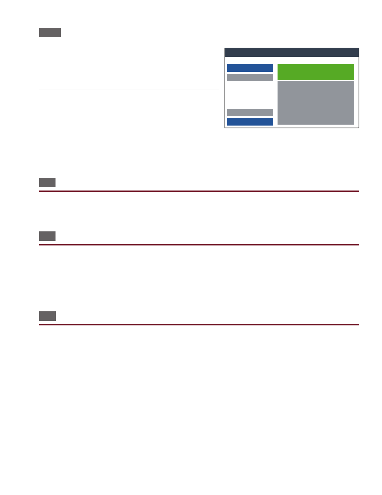
10. Upon completing the test(s), you may want a printed report
summarizing the results. If auto-print was selected from the
System Settings menu, a report will print automatically, or you
can press the Print button to print the report (see page 38 for
printing instructions).
11. If attach cable has been selected, remove the cable to complete
the test. The results of the test will remain on the screen until the
next cable is attached. The Lot information will update to show
the results of the test.
12. At the end of the test—pass or fail—you have the option to retest the cable. Make any necessary adjustments to the
hardware and press Retest. Pressing retest will remove the last recorded test from the Lot information. The retest option
is only available until the cable has been removed.
16.2 Test Results
Test results are displayed in the box on the right side of the screen. If an error occurred, the details of the error will be displayed. See page 36 to learn about interpreting test results.
16.3 Printing Reports
In order for reports to print, the report must be added to the test program during setup.
When you press the Print button, a list of available reports will appear in a window. Select the report you wish to print and
press OK.
If Auto-Print is set up, the report will print automatically upon the predetermined event.
16.4 Using the Probe
In the test window, probe any point on the attached connector to show information pertaining to the probed point. Release
the probe to hide the window. This will help you locate errors within the cable.
Run a Test
35
Page 36

17. Interpreting Test Results
Failed
Failed
Low Voltage Test: Failed
Net 1: OPEN
J1-001 to J1-014
Failed
Failed
Low Voltage Test: Failed
Net 1: OPEN
J1-001 to J1-014
MISWIRE to J1-002
When an assembly fails a test, the Test window will display information about the errors that caused the failure. The following examples show frequent errors operators may encounter:
■ Low Voltage Errors
Low voltage errors identify errors in the cable wire pattern. When
the tester detects a low voltage error, the screen will display detailed
information about the error.
The rst line shows that the low voltage test failed.
The second line describes the type of error.
● OPEN: The intended electrical path contains a gap across
which electric current cannot pass.
● SHORT: An unintended connection between 2 or more points.
This failure indicates insucient insulation between unintended connections.
The third line denes the location of the error. For example, the above image shows an Open error between test points J1-
001 and J1-014.
In the case of a miswire, a fourth line will provide the third point in the
error.
● MISWIRE: An unintended connection which is the result of
unexpected contact. This error is often referred to as an Open
and a Short combined.
The example to the right shows an Open error between test points
J1-001 and J1-014 and a short from J1-014 to J1-002.
■ Component Errors
When the tester creates a new test program containing a component,
it will measure the component value in the sample device and assign
a default tolerance range. During a test, if the tester measures a value
outside of the tolerance range, the component instruction will fail
with an error message that indicates the value measured, as well as the expected value.
Note: You can change the expected component value and the tolerance range by editing the test program in a text editor.
■ High Voltage Errors – 4250 only
Overcurrent Error:
● An overcurrent error occures when the current has exceeded an internal limit during the ramp phase for the net
or point given in the error message. This often means that there is an unintended connection in the device so that
more current is owing than expected as the tester ramps up to the test voltage.
● This error could also be caused when the tester is charging the net or point given in the error message and the
capacitance in the DUT is too high. A limit is in place to ensure safety while testing, so testing is immediately halted
when the limit is reached.
36
Cirris 4200 Series User Manual
Page 37
Dielectric Failure Error:
● This error indicates that an arc occurred during the high voltage test to the net or point given in the error message.
This error will occur anytime the current exceeds the ‘DW Max Current’ test setting.
● This error most often occurs in pairs—Two dierent nets will fail. This generally means that the arc is occurring be-
tween these two nets. If the error occurs only on a single net, it may be the result of a highly capacitive net such as a
shield. The 4250 tester has a setting that can overcome an error caused by highly capacitive shields. See page 20.
■ Leakage Error
This error is an indication that the measured insulation resistance is lower than specied by the IR Resistance test setting.
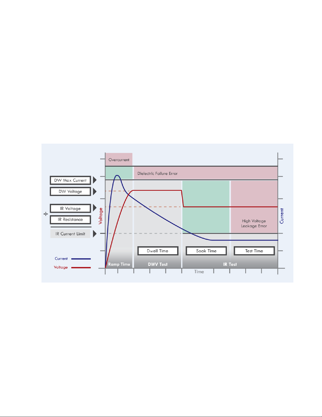
■ HV Errors Graph
The graph represents a normal, good set of high voltage tests. The red line represents voltage while the blue line represents
current. If the blue current line ever enters one of the pink regions, the specied error will result. You can see how high voltage errors, like those descibed above, occur during a high voltage test.
Interpreting Test Results
37
Page 38

18. Printing
The 4200 Series can print full reports or labels. While a label printer can connect direcly to the tester, fullpage reports will
need to be printed from a network printer.
For information on customizing templates, see Reports on page 23.
18.1 Network Printing
The 4200 Series can print from any network printer. This is possible through Cirris Hub Software on a network PC. Once you
install Cirris Hub Software, you will be able to print to any printer connected to the network. See the Cirris Hub Software
Installation Guide for more information.
18.2 Label Printing
4200 Series testers print labels using any Zebra Programming Language (ZPL) capable printer. The printer connects directly
to the 4200 Series tester’s built-in port using a serial cable.
38
Cirris 4200 Series User Manual
Page 39
19. Manage Files
Manage Files
Done
*Double tap folder to open
Delete
New Folder
Copy / Move
NewTest.wir
C:\C:
*
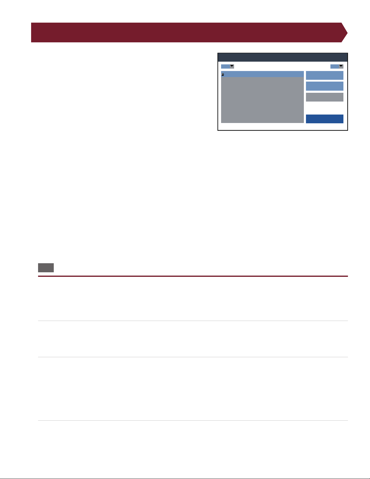
All test programs, report templates, and other les can be accessed
through the Manage Files menu. From this menu, test programs can
be organized, copied, and deleted.
Filter les: Use the drop-down list to lter les. The * symbol shows
all les.
Open a folder: Double-tap on a folder to open it.
Create a new folder: Press the New Folder button, type the name of
the new folder, and press Done.
Return to the previous folder: Double-tap the top folder in the list
labeled with “< >” to return to the previous folder.
Copy a test program: Select a test program and press the Copy/Move button. Navigate to the folder where you wish to
save the copied test program and press Copy. The test program can now be found in both the previous location and the
new location.
Move a test program: Select a test program and press the Copy/Move button. Navigate to the folder where you wish to
save the test program and press Move. The test program will no longer reside in the previous location but will only be found
in the new location.
Delete a test program: Select a program or le and press Delete. Conrm that you want to delete the program or le by
pressing Continue.
WARNING! There is no recovery option after a test program or folder is deleted. Verify the le selected before you delete
any les.
19.1 Test Program Backup via PC Connection
By connecting your tester to a PC, you can move les to and from the PC like you would with a USB ash drive. This allows
you to back up test programs, organize les, and customize labels and reports.
1. Use the PC cable to connect your tester to your PC.
2. Make sure the tester is turned o.
Note: If the tester is running, you will not be able to access it through a PC.
3. When connected to the PC, the tester will behave like a USB drive. You will be able to view and organize les using your
computer’s le management system. With your tester connected to the PC, you can do the following:
a. Organize test programs into folders for easy access.
b. Backup your test programs to your PC.
c. Edit test programs using a text editor and save the revised test program to your tester.
4. When nished, remove the PC cable, or turn the tester back on. Either action will disconnect the tester from the PC.
Manage Files
39
Page 40

WARNING! Do not format your drive. Formatting your drive will permanently erase all test programs and test settings. If
this happens, you must contact Cirris to make your tester operational again.
19.2 Local Test Program Backup via USB Drive
To back up test programs:
1. Insert a USB drive into the USB port on your tester.
2. Copy your test programs onto the USB drive.
3. Remove the USB. With the test programs on the USB drive, you can save them onto a PC for safe keeping or for editing
through a text editor.
Other USB drive uses:
● Update Firmware.
● Copy test programs between 4200 Series testers.
● Copy test programs between the tester and a PC.
40
Cirris 4200 Series User Manual
Page 41
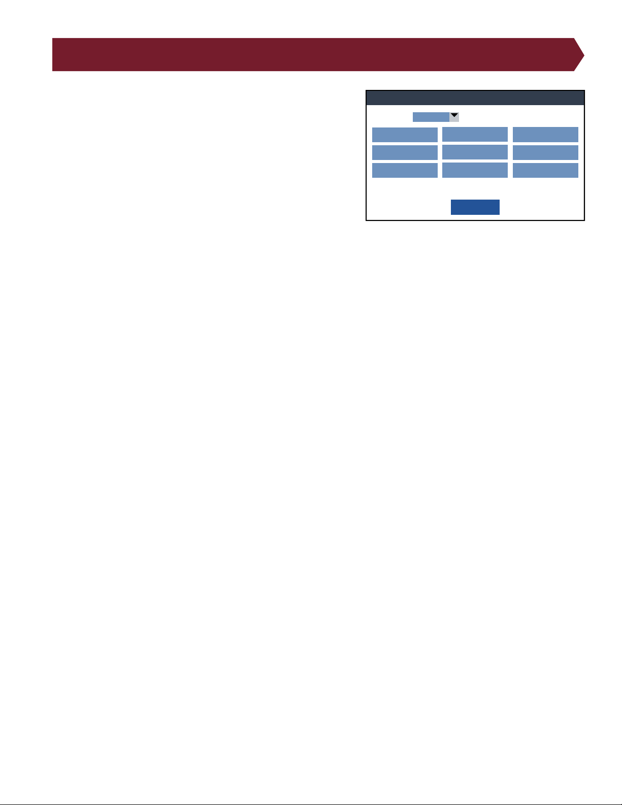
20. System Settings
System Settings
Done
Volume:
20%
Legacy Defaults Network Settings
Date:
MM-DD-YY
Mains Frquency:
60 Hz
Features
Time:
HH:MM:SS
System Diagnostic About
Language:
English
•
● Change Language: Change the language of the Cirris OS
software.
● Volume: Adjust tester volume.
● Date: Set the date and adjust the date layout.
● Time: Set the clock for your local time and adjust the clock
layout.
● Legacy Defaults: Reproduces the 1100 Series behavior on a
4200 Series. See page 42.
● Mains Frequency: Also known as Power Line Frequency, you
will want to set this value to 50 or 60Hz depending on your
country’s AC line frequency. The Correct selection will improve test measurement accuracy.
● System Diagnostic: Upon startup, the tester will run a self-test to verify that the system is functioning correctly. If
you suspect anything wrong with the tester, you can run a self-test. If the tester fails a self-test, a window will open
with a description of the details of the failure. Note the details of the failure and contact Cirris Tech Support.
● Network Settings: Adjust settings to connect to a network. For more information, see the Cirris Hub Software Man-
ual.
● Features: After purchasing a new feature from Cirris, enter the feature key into this menu to access that feature.
● About: Access and Edit information about your tester such as the station name, serial number, and more.
System Settings
41
Page 42

21. Legacy Defaults
On legacy CIrris testers such as the 1100 Series, test preferences, settings, reports, and digital I/O were controlled on a
tester level. This means changes aected all test programs globally. On the 4200 Series, settings are controlled on a testby-test basis. If you change one test program, it has no eect on other test programs.
To use test programs from a legacy tester, set the Legacy Defaults on your 4200 Series tester to match the system settings
of your legacy Cirris tester.
Once a legacy test program has been edited and saved on a 4200 Series tester, the new test-level settings will be applied.
The same test program can still beused on an legacy Cirris tester with the legacy tester applying its own system settings.
42
Cirris 4200 Series User Manual
Page 43
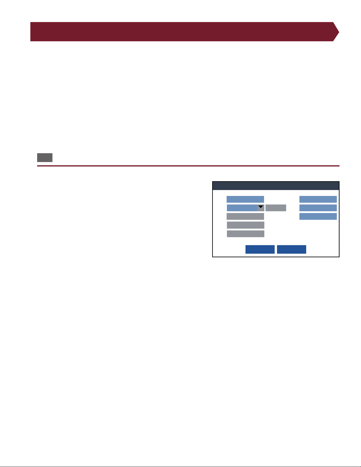
22. Network Settings
Network Settings
Cancel
Done
None
Refresh
Ethernet
Mode:
SSID:
Enter Username
Pre-Shared Key
Auth Mode:
Username:
Enter Password
Password:
Enter Server Port
Enter Server IP
Server:
Port:
Add CA Cert
In order to print, the 4200 Series must be connected to a network running Cirris Hub Software. To set this up, from the
Main Menu, select System Settings, and then Network Settings. The options on this screen will allow your tester to communicate with a network running Cirris Hub Software.
Note: An IT professional will likely need to help you in setting up your tester network settings.
■ Choosing between Ethernet or Wi-Fi
Ethernet is the most reliable method for connecting your tester to the Hub network. Once you have entered the settings for
Ethernet and Wi-Fi, you may switch between one or the other by simply by changing the Mode in Network Settings.
22.1 Ethernet
Cirris suggests using Ethernet whenever possible to ensure a reliabel
connection.
1. Using an Ethernet cable, connect your tester to the same network
router or switch that is connected to the PC running Cirris Hub
Software.
2. On the Network Settings screen:
● Mode: Ethernet.
● Server: IP address for the computer running Cirris Hub Soft-
ware.
○ The tester will automatically detect the IP address of the
computer running Cirris Hub Software If the tester is on the same subnet.
○ Enter the IP address or host name of the computer running Cirris Hub Software if the network service is not de-
tected.
Note: Generally, you will want to have a static IP address assigned to the computer running Cirris Hub Software.
● Port: You do not have to enter a port if the tester automatically detects the Cirris Hub Server on its subnet. The de-
fault port is 12568 or enter the port number as set up by the IT administrator.
3. Press Done. The tester should say Connecting to the Hub then return to the System Settings screen. When you load a
test from the Main Menu, you will notice that you can select F: drive.
Your tester should now appear on the list of available testers in Cirris Hub Software. See the Cirris Hub Software Installation
Guide for more information.
Network Settings
43
Page 44
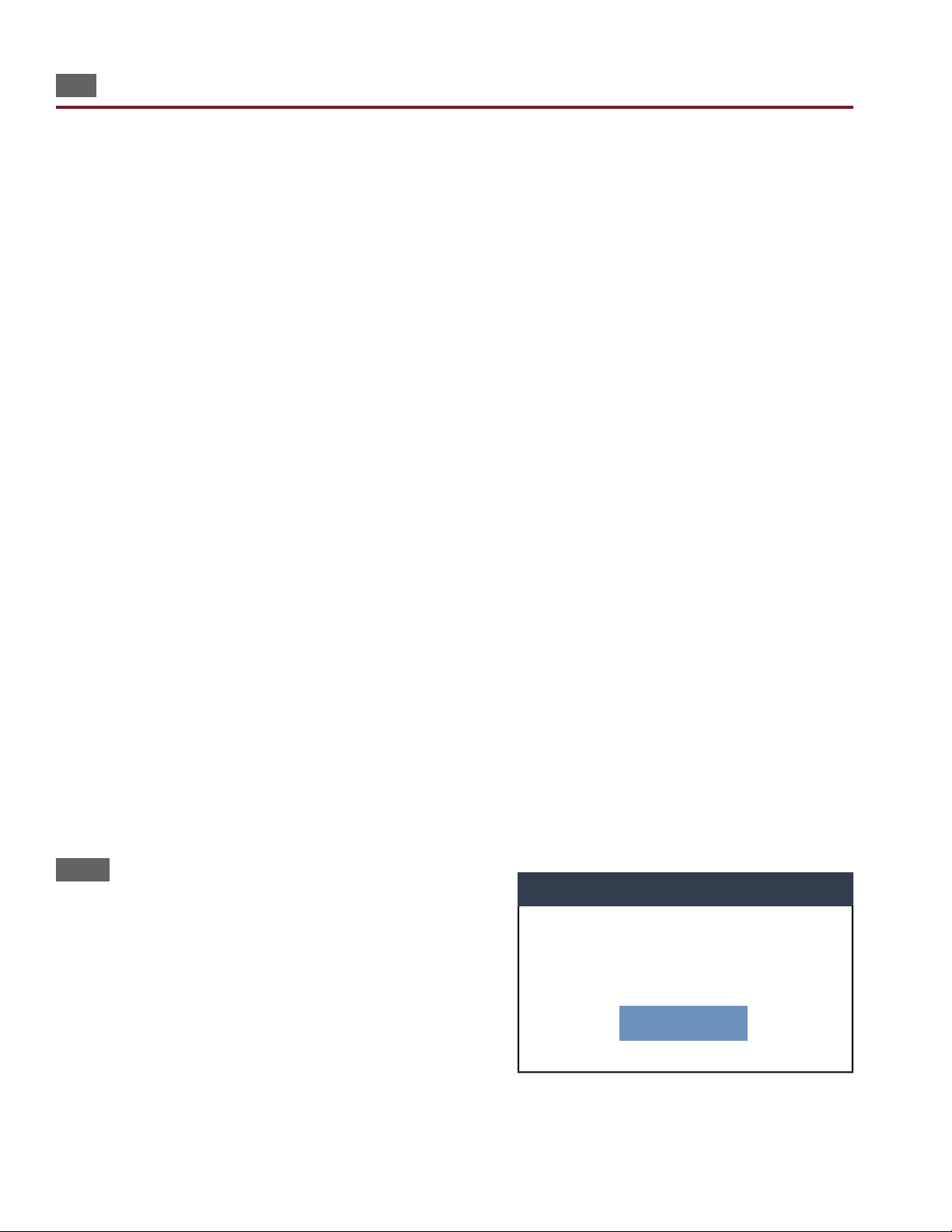
22.2 Wi-Fi
Network Settings
Connecting to Cirris Hub...
Initializing ...
Cancel
Warning: When using Wi-Fi, you may on occasion notice the tester pause to reestablish network communication. Cirris
recommends using a wired connection.
1. On the Network Settings screen:
● Mode: WiFi
● SSID: Press Refresh then select the wireless network from the dropdown list.
Note: The name of the wireless network must be broadcast. The tester is not capable of connecting to a non-broadcast
wireless network.
● Auth Mode: Select Enterprise or Pre-shared Key depending on your network environment.
● Username: Enter the Username if using the Enterprise mode.
● Password: Enter the password to connect to the network.
● Server: Server: IP address for the computer running Cirris Hub Software.
○ The tester will automatically dtetct the IP address of the computer running Cirris Hub Software If the tester is on
the same subnet.
○ Enter the IP address or host name of the computer running Cirris Hub Software if the network service is not de-
tected.
● Port: You do not have to enter a port if the tester automatically detects the Cirris Hub Server on its subnet. The de-
fault port is 12568 or enter the port number as set up by the IT administrator.
● If a client CA Certicate is required, insert a USB drive containing the certicate into the USB port on the back of the
tester. Press Add CA Cert to access the certicate.
2. Press Done. The tester should say Connecting to the Hub then return to the System Settings screen. When you load a
test from the Main Menu, you will notice that you can select F: drive.
Your tester should now appear on the list of available testers in Cirris Hub Software. See the Cirris Hub Software Installation
Guide for more information.
22.2.1 Connecting to Cirris Hub...
Depending on your environment, network, and other conditions, you
may experience occasional pauses when using Wi-Fi. These pauses
can last several seconds while a window blocks the tester screen. Do
not press cancel. Wait for the tester to connect to the network. Once
the tester reconnects, the window will disappear and the test process
can resume.
44
Cirris 4200 Series User Manual
Page 45

23. High Voltage Guidelines (4250 only)
Use the following considerations to determine high voltage specications:
● Customer needs, engineering necessities, or manufacturer’s specications for wires and connectors.
Note: Do not confuse the rated running voltage with a maximum hipot value.
● Voltage applied to a cable which may be limited by the spacing between pins in a connector and the separation of
the conductors in a cable.
● Available high voltage selections for the Insulation Resistance Settings (see page 21) see the table below.
● Highly capacitive cables that the amount of high voltage that can be applied to the cable.
■ HV Insulation Resistance Table
The “HV Insulation Resistance” settings are limited by the high voltage settings. The table below shows the available
Insulation Resistance settings at each of the high voltage settings.
Voltage Min IR (Meg) Max IR
100 V 10 100
200 V 20 200
300 V 30 300
400 V 40 400
500 V 50 500
600 V 60 600
700 V 70 700
800 V 80 800
900 V 90 900
1000 V 100 1000
■ HV Insulation Resistance Guidelines
IR Settings may be based on any of the following factors:
● Contamination: Fingerprints and mold release on your DUT may require you to lower the IR threshold.
● Humidity: A humid environment can aggravate the eects of contamination between contacts and aect insulation.
■ High Voltage Duration:
Insulation Resistance Duration may be set using the following guidelines:
High Voltage Guidelines (4250 only)
45
Page 46

● The default setting of 0.010 seconds (10 milliseconds) should be adequate to test most cables. A longer duration will
increase the high voltage test time.
● Since absorbed moisture may not have time to be “dried out” before the Insulation Resistance Test, consider using
the advaned Soak setting to “dry out” your insulation. A shorter soak time or not having soak time is more likely to
fail due to humidity related problems
Dielectric Withstand Duration
● A longer duration provides a more stringent test for predicting dielectric failures (exhibited as sudden arcs); howev-
er, equivalent dielectric errors can be found by compensating a shorter duration with a higher high voltage setting.
● A longer duration may be better for predicting some types of insulation failures and may increase the chance of
detecting a breakdown condition.
46
Cirris 4200 Series User Manual
Page 47
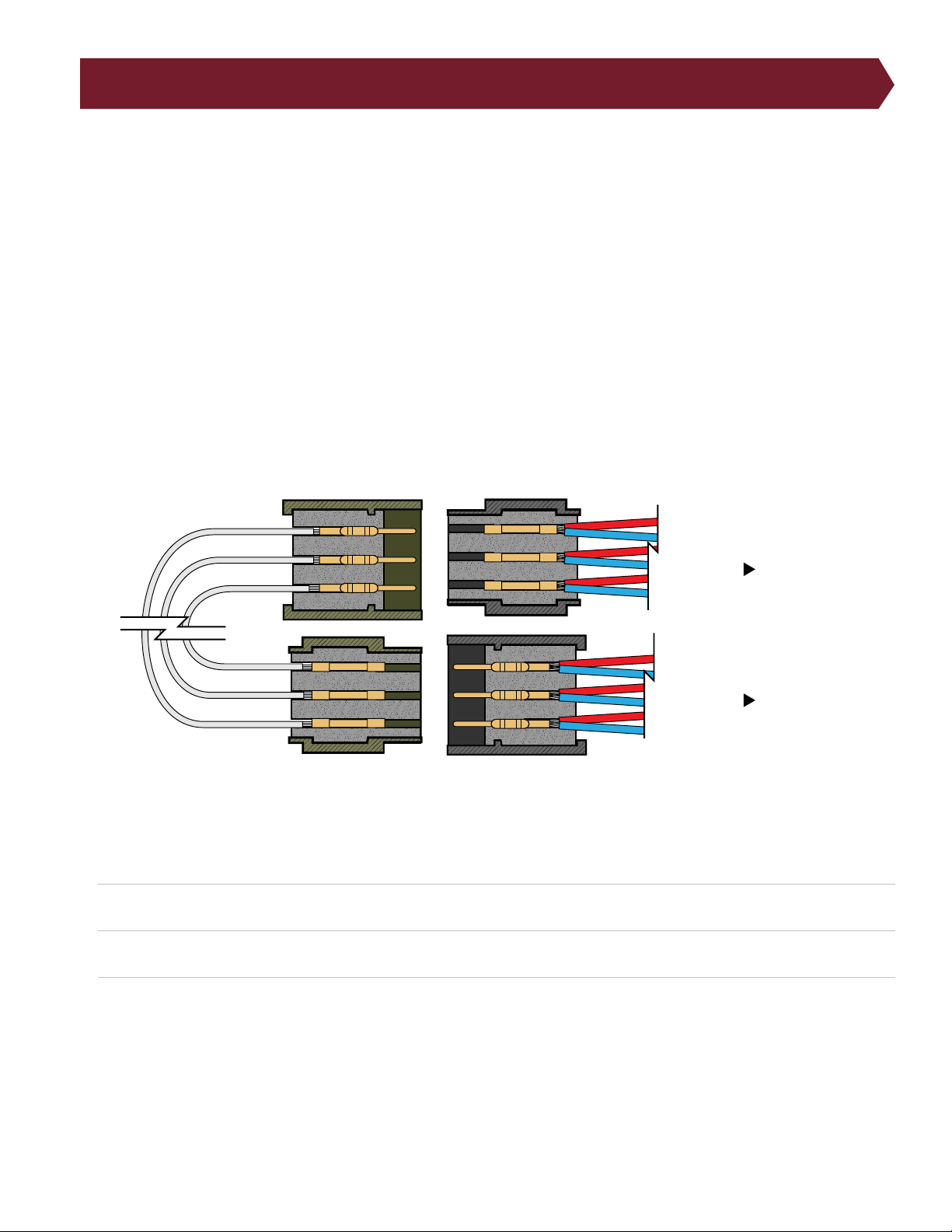
24. Four-Wire Kelvin Testing
To measure resistance, the tester sends a current through a wire and measures how much the voltage drops. It then
calculates the resistance using Ohm’s Law. Since voltage is measured through the xturing, any resistance caused by
xturing is included within that measurement. four-wire Kelvin testing eliminates the resistance of xturing and can
measure resistances down to .001 Ohm. The cost of this measurement accuracy is that twice as many test points are
required.
The four-wire measurement requires two correctly paired test points for every connection.
● One test point supplies current (referred to as “force”)
● The other senses voltage (referred to as “sense”)
For the purpose of four-wire testing using the 4200 Series, test points are considered either Type 1 (T1) or Type 2 (T2) points.
The tester uses T1 points as either force or sense; it uses T2 points as the compliment. Each four-wire pair from the tester
must have one of each point.
The following illustration shows a common way wires attached to the T1 and T2 test points could connect to the pins and
cavities in the mates-to-DUT connector.
Device Under Test
On a 4200 Series tester, you can tell which type each test point is by probing the point while setting up a Learn.
1. From the Main Menu, press Create New.
2. From the Learn menu, press Edit Learn Settings, then press Components.
Fixturing
to tester
to tester
3. In the Components menu, press Learn Four-Wire and press OK. (Press OK again to return to the Learn menu.)
4. With only the xturing attached to the tester, press Learn Attached Device. A window will appear instructing you to
Attach Four Wire Fixture. When this window appears, touch the tip of the probe to a pin on your connector. You will
hear a tone and see a window specifying if the point is Type 1 or Type 2.
Note: Once the test program is Learned with four-wire included, the netlist will only show one test point of each four-wire
pair. It will count the rst test point it nds. This means If the points are wired in numerical order, the tester will count every
other point. (J1-001, J1-003, J1-005…) If you want the tester to list each test point in numerical order, you will need to
Four-Wire Kelvin Testing
47
Page 48

make sure that each four-wire pair contains the test point you want to be numbered and a separate test point elsewhere
on the tester (for example, on a dierent connector).
The location where the four-wire pair physically joins the test point connection of the device-under-test should be placed
as close to the device-under-test as possible. The tester will measure any resistance from the xturing exposed after the
four-wire pair joins together.
For more information on four-wire testing, visit cirris.com.
48
Cirris 4200 Series User Manual
Page 49

25. Calibration
Every Cirris tester leaves the factory callibrated according to industry standards. Every two years, the tester will need to be
checked to ensure it still meets calibration requirements.
Cirris sells Performance Check Kits that run a series of tests to determine if your tester meets calibration standards. If the
tester passes the performance check, your tester is certied to run for another two years.
If your tester fails the performance check, speak to your Cirris sales rep. Cirris or a third party lab can calibrate your tester. No
external adjustments can be made to x the tester’s calibration.
Do not open the tester chassis or make any attempt to calibrate the tester yourself. This action will void your tester’s
warranty.
Calibration
49
Page 50

26. Connecting to Easy-Wire™
You can operate your 4200 Series tester from a PC using Cirris Easy-Wire Software. Use the provided USB cable to connect
your tester to a PC that is running Easy-Wire. Contact your sales representative for information on obtaining a software
license.
Easy-Wire Software provides extra features and benefits such as:
● More reporting options
● Compatibility with other Cirris testers
● More detailed test creation
● And other features
See cirris.com for more information.
50
Cirris 4200 Series User Manual
Page 51
27. Frequently Asked Questions
How can I know what values to use in each test setting?
If settings are not specied in the cable build instructions and you are hesitant about using the default settings in the software, you can turn to the industry accepted wire assembly guide, A-620. More information about this guide can be found
by visiting cirris.com.
You can also calculate some settings using tools such as the Cirris calculators found at cirris.com.
Is high voltage testing dangerous?
Cirris testers are designed to comply with product safety regulations and are thus intrinsically safe. However, during a high
voltage test, there may be some risk. Children, women who are pregnant, and people with pacemakers should not perform
high voltage testing. For more ideas on high voltage safety, visit cirris.com.
How do I calibrate my tester?
The act of calibrating a tester should only be performed by Cirris or a third-party calibration lab. To verify calibration and
functionality, you can purchase a Performance Check Kit from Cirris.
Every Cirris tester that leaves our factory is calibrated in compliance with ANSI/NCSL Z540-1-1994 and ISO-10012 to standards traceable to the NIST in the United States. For more information, visit cirris.com.
The calibration of the tester should be veried annually.
Where do I nd current manuals?
The most current manuals can be found by contacting your Cirris representative or visiting cirris.com.
27.1 Service and Maintenance
■ General Maintenance
Do not open the tester chassis. Opening the chassis will void your warranty. The 4200 Series tester contains no internal user
serviceable parts. Cleaning or routine maintenance of internal parts should be done at Cirris.
Do not try to replace the lithium battery on the MCAN board. Should this battery, or any internal parts malfunction, contact
Cirris for a repair.
Any exterior cleaning should be done using a clean, damp rag. Avoid using cleaning agents or chemicals on any part of the
unit.
27.2 Connector Maintenance
The DB-25 Connectors on the front of your tester are made to be durable, but over time the connectors can be damaged
either from age or abuse/misuse. To protect your tester’s connectors:
● Never insert foreign objects into your connectors.
● Keep the connectors free of dust and debris.
● Be mindful of bent pins or other problems with mating connectors.
Frequently Asked Questions
51
Page 52

27.3 Repair
Should your tester require repair, contact your Cirris representative for a free estimate. Depending on the extent of the damage, you may have to send your tester to Cirris headquarters.
52
Cirris 4200 Series User Manual
Page 53
28. Factory Defaults
The following table lists the settings for the 4200 Series testers and their corresponding factory defaults.
Preferences
Low Voltage Start Cable Attach
High Voltage Start Start Button
HV Auto Start Delay 1.0 S
Intermittents Test For Duration
Intermittents Test Duration 2 S
Enter Lot ID OFF
External Start Switch OFF
External Safety Switch OFF
LV Settings
Connection Resistance 10.0 ohm
LV Insulation Resistance 100 k ohm
High Voltage - 4250 only
High Voltage ON
HV Basic Settings
High Voltage 50 V
Insulation Resistance 5 M ohms
Dwell Time 2 mS
HV Advanced Settings
DW Voltage 50 V
DW Max Current 0.1 mA
DW Dwell Time 10 mS
Factory Defaults
53
Page 54

HV Advanced Settings
AC Frequency 60Hz
Cycles 1 Cycle
IR Voltage 50 V
IR Minimum Resistance 50 M ohm
IR Dwell Time 2 mS
IR Soak Time 0 S
Soak Until Good OFF
Components Settings
All OFF
Data Collection
Data Collection OFF
Measured Values OFF
Error Text OFF
System Settings
Volume 20
Date MM_DD_YY
Time 24
Mains Frequency 60 Hz
54
Cirris 4200 Series User Manual
Page 55

29. Troubleshooting
Visit www.cirris.com/learning-center for articles on troubleshooting. If you need additional help, contact Cirris Technical
Support at [email protected] or 1-800-441-9910 ext 666.
■ A high percentage of tests fail
Too many tests failing could be caused by several possibilities.
● Error in the Learned device: If a cable with mistakes or defects is used as the primary cable to create the test pro-
gram, then all good cables will fail because they are tested using bad test instructions.
● Fixturing: Failures can occur if the xturing is not built and connected correctly. See the Fixturing section of this
manual for help (page 12).
● Tester Interface/Unit: A problem with the tester may occur on the tester interface (the part of the tester visible
to the user), or within the tester unit (the wiring and other pieces contained inside the chassis). Problems with the
tester interface might be repairable by the user while problems with the tester unit should be evaluated by the
tester manufacturer. If you suspect a problem with your tester unit, verify your tester is calibrated. You can purchase
a verication kit from Cirris. If necessary, you may have to send the tester to Cirris for repair.
● High Voltage – 4250 only: To troubleshoot a high voltage failure such as a dielectric failure, remove the DUT and
Learn a new test program with the same high voltage settings. The tester may display a warning indicating no
connections are found. Proceed to perform the Learn and test. If the same dielectric failure occurs, the problem is
either with the test xture or the tester interface. If possible, try testing the same device with dierent xturing. If the
problem still occurs, the error is the most likely source of the problem.
● Environment: Occasionally failures can be caused by factors in the environment such as humidity and materials. For
example:
○ Humidity: Humidity related IR failures will usually report as an IR or HV leakage failure. High humidity can allow
moisture paths for small amounts of current to ow between unintended connections.
○ Materials: Consider the materials selected, the type of environment you operate in, and the number of cycles the
xturing can endure. If there is any question of suitability in materials, try looking at the manufacturer’s specications.
■ No Sound
The tester uses sound prompts to provide feedback to the operator. If the tester is not making any sound, check the tester
volume.
1. From the Main Menu, press System Settings.
2. Press the Volume button.
3. If the volume is set to 0, the tester will not make any sounds. Enter a number between 1-100.
Troubleshooting
55
Page 56

30. Glossary
Adapters: Interchangeable devices with connectors that attach the the cable being tested to the tester
Connections: The continuous electrical path between 2 or more points wherein current ows. The path is constructed with
metal parts, such as copper wire, contacts, terminations, splices, and mating contacts of connectors.
Device-Under-Test (DUT): The cable, harness, or other assembly that is being tested by the cable tester.
Dielectric Withstand (DW): The tester applies the required voltage for the determined amount of time and watches for
current ow. Ideally, no current ows and the cable is not harmed.
Fixturing: The test interface or adapter cables that connect the device-under-test to the tester.
Hipot/High Voltage Test: A high voltage or hipot test checks for “good isolation.” This test checks that no current ows
between points where there should be no current.
Intermittent Errors: Errors that occur sporadically or inconsistently.
Intermittents Test: Gives the operator a chance to move and ex the cable, searching for intermittent errors.
Insulation Resistance (IR): The test applies a voltage and measures the current to determine if the resistance of the
insulation is high enough.
Had Leakage error: Occurs because more current than is acceptable leaks between unconnected points.
Learn: The process of the tester scanning a known-good cable to create a test program.
Low Voltage Test: The tester applies a current to the wire and measures the voltage. If the wire is connected correctly,
the test will read low resistance, meaning current is owing through the wire as expected and reaching the required
connections.
Miswire: An unintended connection which is the result of a misplaced contact within a connector.
Net: Two or more interconnected points in a cable or harness.
Open: The intended electrical path contains a gap across which electric current cannot pass.
Overcurrent error: A larger amount of the current is able to ow through the wire than the tester expects.
Short: An unintended connection between 2 or more parts. This failure indicates insucient insulation between metal
conductors which were not intended to be connected.
Test Program: The list of instructions used to test cables and harnesses.
56
Cirris 4200 Series User Manual
Page 57

31. Specifications
■ Test Points
128 points; expandable to 1024 points in 128-point increments
■ Low Voltage Test
2 Wire
● Voltage: 4 V max
● Current: 3 A to 6 mA
● Resistance: 0.1 to 100 k ± 1% ± 0.1 , 100k to 5 M ± 10%
4 Wire
● Voltage: 4 V max
● Current: 1 mA to 1 A
● Resistance: 0.001 to 10 ± 2% ± 0.001
Component Tests
● Diodes: Silicon, LEDs, zeners with breakdown > 4V
● Resistors: 0.1 to 100k ± 1% ± 0.1 , 100 k to 5 M ± 10%
● Capacitors: 5 nF to 100 F ±10% ± 0.02 nF
● Twisted Pairs: Verify proper pairing in twisted pair cables
■ High Voltage Test – 4250 only
Insulation Resistance Test
● Voltage: 50 to 1500 VDC ± 5% ± 5 V (2000 VDC optional)
● Resistance: 5M to 1000 M ± 10%
Dielectric Withstand Test
● Voltage: 50 to 150 VDC ± 5% ± 5 V (2000 VDC optional, 50 to 1000 VAC optional)
● Current Limit: 0.1 mA to 1.5 mA
● Max Capacitance Per Net: 150 nF @ 300 VDC, 90 nF @ 500 VDC,
45 nF @ 1000 VDC, 30 nF @ 1500 VDC, 9.5 nF @ 1000 VAC
● HV Energy Limit: 35 mJ
● HV Charge Limit: 45 C
■ Max Points per Net
100
Specications
57
Page 58

■ Digital Input/Output
4 Inputs / 6 Outputs, 24 V Open collector, +10 V and +5 V each current limited to 100 mA
■ Test Point Interface
Cirris Adapter System
■ User Interface
● Display: 7 x 3.5" color graphical display with capacitive touch screen (800 X 480-pixel resolution).
● Localization: English, German, Spanish with ability to translate to other languages as needed.
● Memory: Internal memory for test program storage (8 GB or more).
● File transfer: Transfer test programs either by connecting directly to a PC or using a USB ash drive.
● Printing: Local label printing via serial ports. Network printing via Cirris Hub™ Software.
● Optional PC control: Additional advanced features via Easy-Wire™ Software.
■ Power
105 -135 V, 60 Hz, 210 -260 V, 50 Hz
■ Size
● Main Unit: 17.35" x 6.47" x 7.08" (44.07 cm x 16.43 cm x 17.98 cm)
● Add-on Box: 6.24" x 5.22" x 7.08" (15.85 cm x 13.26 cm x 17.98 cm)
■ Weight
● Main Unit: 11.35 lb (5.15 kg)
● Add-on Box: 5.00 lb (2.27 kg)
All Cirris products are manufactured in Salt Lake City, Utah, United States of America.
58
Cirris 4200 Series User Manual
Page 59

Specications
59
Page 60

Cirris 4200 Series User Manual
Version 2019.2.1
© 2018 Cirris Systems Corporation
401 North 5600 West
Salt Lake City, Utah 84116
U.S.A.
www.cirris.com
 Loading...