

Page 1
Maximum demand control
MDC-4
INSTRUCTION MANUAL
(M013B01-03-15C)
Page 2

MDC-4
2
Instruction Manual
Page 3
MDC-4
SAFETY PRECAUTIONS
Follow the warnings described in this manual with the symbols shown below.
DANGER
Warns of a risk, which could result in personal injury or material damage.
ATTENTION
Indicates that special attention should be paid to a speci c point.
If you must handle the unit for its installation, start-up or maintenance, the following
should be taken into consideration:
Incorrect handling or installation of the unit may result in injury to personnel as well as damage
to the unit. In particular, handling with voltages applied may result in electric shock, which may
cause death or serious injury to personnel. Defective installation or maintenance may also
lead to the risk of re.
Read the manual carefully prior to connecting the unit. Follow all installation and maintenance
instructions throughout the unit’s working life. Pay special attention to the installation standards of the National Electrical Code.
Refer to the instruction manual before using the unit
In this manual, if the instructions marked with this symbol are not respected or carried out correctly, it can
result in injury or damage to the unit and /or installations.
CIRCUTOR, SA reserves the right to modify features or the product manual without prior noti cation.
DISCLAIMER
CIRCUTOR, SA reserves the right to make modi cations to the device or the unit speci ca-
tions set out in this instruction manual without prior notice.
CIRCUTOR, SA on its web site, supplies its customers with the latest versions of the device
speci cations and the most updated manuals.
www.circutor.com
Instruction Manual
3
Page 4

MDC-4
CONTENTS
SAFETY PRECAUTIONS ���������������������������������������������������������������������������������������������������������������������������������������3
DISCLAIMER ����������������������������������������������������������������������������������������������������������������������������������������������������������3
CONTENTS ������������������������������������������������������������������������������������������������������������������������������������������������������������� 4
REVISION LOG �������������������������������������������������������������������������������������������������������������������������������������������������������5
1�- VERIFICATION UPON RECEPTION ����������������������������������������������������������������������������������������������������������������� 6
2�- PRODUCT DESCRIPTION �������������������������������������������������������������������������������������������������������������������������������� 6
3�- UNIT INSTALLATION ���������������������������������������������������������������������������������������������������������������������������������������� 7
3�1�- PRIOR RECOMMENDATIONS�������������������������������������������������������������������������������������������������������������������7
3�2�- INSTALLATION ������������������������������������������������������������������������������������������������������������������������������������������8
3�3�- UNIT TERMINALS �������������������������������������������������������������������������������������������������������������������������������������� 9
3�4�- CONNECTION DIAGRAM ������������������������������������������������������������������������������������������������������������������������ 10
3�4�1�- Three-phase network measurement with a 4-wire connection� ��������������������������������������������������� 10
3�4�2�- Three-phase network measurement with a 3-wire connection� ��������������������������������������������������� 11
3�4�3�- Single-phase network measurement� ���������������������������������������������������������������������������������������������12
4�- OPERATION ���������������������������������������������������������������������������������������������������������������������������������������������������13
4�1�- OPERATING PRINCIPLE ������������������������������������������������������������������������������������������������������������������������� 13
4�2�- PARAMETERS �����������������������������������������������������������������������������������������������������������������������������������������14
4�3�- KEYS FUNCTIONS ����������������������������������������������������������������������������������������������������������������������������������15
4�4�- DISPLAY ���������������������������������������������������������������������������������������������������������������������������������������������������15
4�5�- LED INDICATORS ������������������������������������������������������������������������������������������������������������������������������������ 16
4�6�- DISPLAY IMPROVEMENTS ���������������������������������������������������������������������������������������������������������������������17
4�6�1�- Maximum demand screens� ������������������������������������������������������������������������������������������������������������17
4�6�2�- Measuring screens� ��������������������������������������������������������������������������������������������������������������������������18
4�7�- OUTPUT RELAYS ������������������������������������������������������������������������������������������������������������������������������������19
4�8�- PROGRAMMING �������������������������������������������������������������������������������������������������������������������������������������� 19
4�8�1� Current primary ���������������������������������������������������������������������������������������������������������������������������������19
4�8�2� Selecting the maximum demand variable ��������������������������������������������������������������������������������������� 20
4�8�3� Period of maximum demand integration �����������������������������������������������������������������������������������������20
4�8�4� Contracted power ������������������������������������������������������������������������������������������������������������������������������ 20
4�8�5� Deleting the maximum demand maximum value� ������������������������������������������������������������������������� 20
4�8�6� Deleting the energy value ����������������������������������������������������������������������������������������������������������������� 21
4�8�7� Deleting the output relay disconnection times� �����������������������������������������������������������������������������21
4�8�8� Level of output relay no� 1 ���������������������������������������������������������������������������������������������������������������� 21
4�8�9� Hysteresis of output relay no� 1 ������������������������������������������������������������������������������������������������������� 21
4�8�10� Delay in connecting output relay no� 1 �����������������������������������������������������������������������������������������22
4�8�11� Delay in disconnecting output relay no� 1 ������������������������������������������������������������������������������������22
4�8�12� Status of the contacts for output relay no� 1 �������������������������������������������������������������������������������� 22
4�9�- PROGRAMMING THE CURRENT DATE AND TIME ������������������������������������������������������������������������������23
4�9�1� Day ������������������������������������������������������������������������������������������������������������������������������������������������������ 23
4�9�2� Month ��������������������������������������������������������������������������������������������������������������������������������������������������23
4�9�3� Year ����������������������������������������������������������������������������������������������������������������������������������������������������� 24
4�9�4� Time ���������������������������������������������������������������������������������������������������������������������������������������������������� 24
4�9�5� Minutes ����������������������������������������������������������������������������������������������������������������������������������������������� 24
5�- TECHNICAL FEATURES ��������������������������������������������������������������������������������������������������������������������������������25
6�- MAINTENANCE AND TECHNICAL SERVICE ������������������������������������������������������������������������������������������������27
7�- GUARANTEE ���������������������������������������������������������������������������������������������������������������������������������������������������27
8�- CE CERTIFICATE �������������������������������������������������������������������������������������������������������������������������������������������� 28
4
Instruction Manual
Page 5

MDC-4
REVISION LOG
Table 1: Revision log�
Date Revision Description
09/14 M013B01-03-14A Initial Version
03/15 M013B01-03-15A
04/15 M013B01-03-15B
06/15 M013B01-03-15C
Changes in the following sections:
3.4. - 4.1. - 4.8.7.
Changes in the following sections:
4.2.- 4.6.1.- 4.6.2 - 4.8
Changes in the following sections:
4.8 - 5
Note: Unit images are for illustrative purposes only and may differ from the actual unit.
Instruction Manual
5
Page 6
MDC-4
1�- VERIFICATION UPON RECEPTION
Check the following points upon receiving the unit:
a) The unit meets the specications described in your order.
b) The unit has not suffered any damage during transport.
c) Perform an external visual inspection of the unit prior to switching it on.
d) Check that it has been delivered with the following:
- An installation guide.
If any problem is noticed upon reception, immediately contact the transport
company and/or CIRCUTOR's after-sales service.
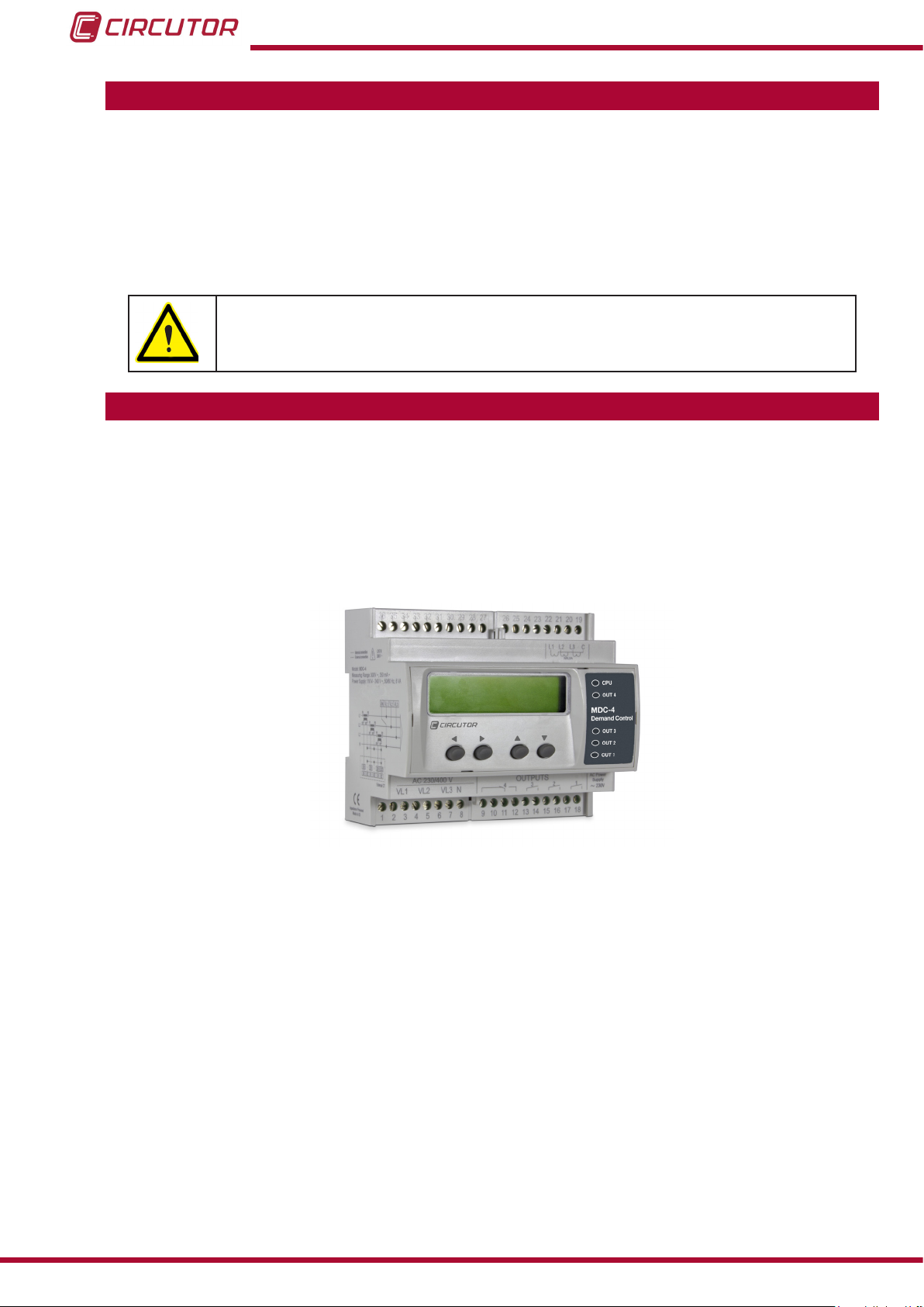
2�- PRODUCT DESCRIPTION
The MDC-4 unit controls maximum power demand, both in single and three-phase installations
with and without neutral. The unit is equipped with a power analyzer that measures electrical
parameters at the connection point. The measurement is taken in RMS, via four AC voltage
inputs and four current inputs.
The current is measured indirectly with efcient transformers of the MC1 and MC3 series.
The unit features:
- 4 output relays, to disconnect and connect the loads.
- 4 keys, to browse through the different screens.
- 5 indicator LEDs, to show the status of the loads and the CPU.
- 1 Display, for viewing all the parameters.
6
Instruction Manual
Page 7
MDC-4
3�- UNIT INSTALLATION
3.1.- PRIOR RECOMMENDATIONS
In order to use the unit safely, it is critical that individuals who handle it follow
the safety measures set out in the standards of the country where it is being
used, use the necessary personal protective equipment, and pay attention to
the various warnings indicated in this instruction manual.
The MDC-4 unit must be installed by authorised and qualied staff.
The power supply plug must be disconnected and measuring systems switched off before handling, altering the connections or replacing the unit. It is dangerous to handle the unit while it is
powered.
Also, it is critical to keep the cables in perfect condition in order to avoid accidents, personal
injury and damage to installations.
The manufacturer of the unit is not responsible for any damage resulting from failure by the
user or installer to observe the warnings and/or recommendations set out in this manual, nor for
damage resulting from the use of non-original products or accessories or those made by other
manufacturers.
If an anomaly or malfunction is detected in the unit, do not use it to take any measurements.
Inspect the work area before taking any measurements. Do not take measurements in dangerous areas or where there is a risk of explosion.
Disconnect the unit from the power supply (unit and measuring system power
supply) before maintaining, repairing or handling the unit's connections.
Please contact the after-sales service if you suspect that there is an operational
fault in the unit.
Instruction Manual
7
Page 8
MDC-4
3.2.- INSTALLATION
The unit is installed on a DIN rail.
The unit must be mounted inside an electric panel.
The unit must be connected to a power circuit that is protected with gL fuses (IEC 269) or M
fuses, with a rating of 1 to 2 A. It must be tted with a circuit breaker or equivalent device for
disconnecting the unit from the power supply mains.
The power and voltage measuring circuit must be connected with cables that have a minimum
cross-section of 1mm2.
Terminals, opening covers or removing elements can expose parts that are
hazardous to the touch while the unit is powered. Do not use the unit until it is
fully installed.
8
Instruction Manual
Page 9
MDC-4
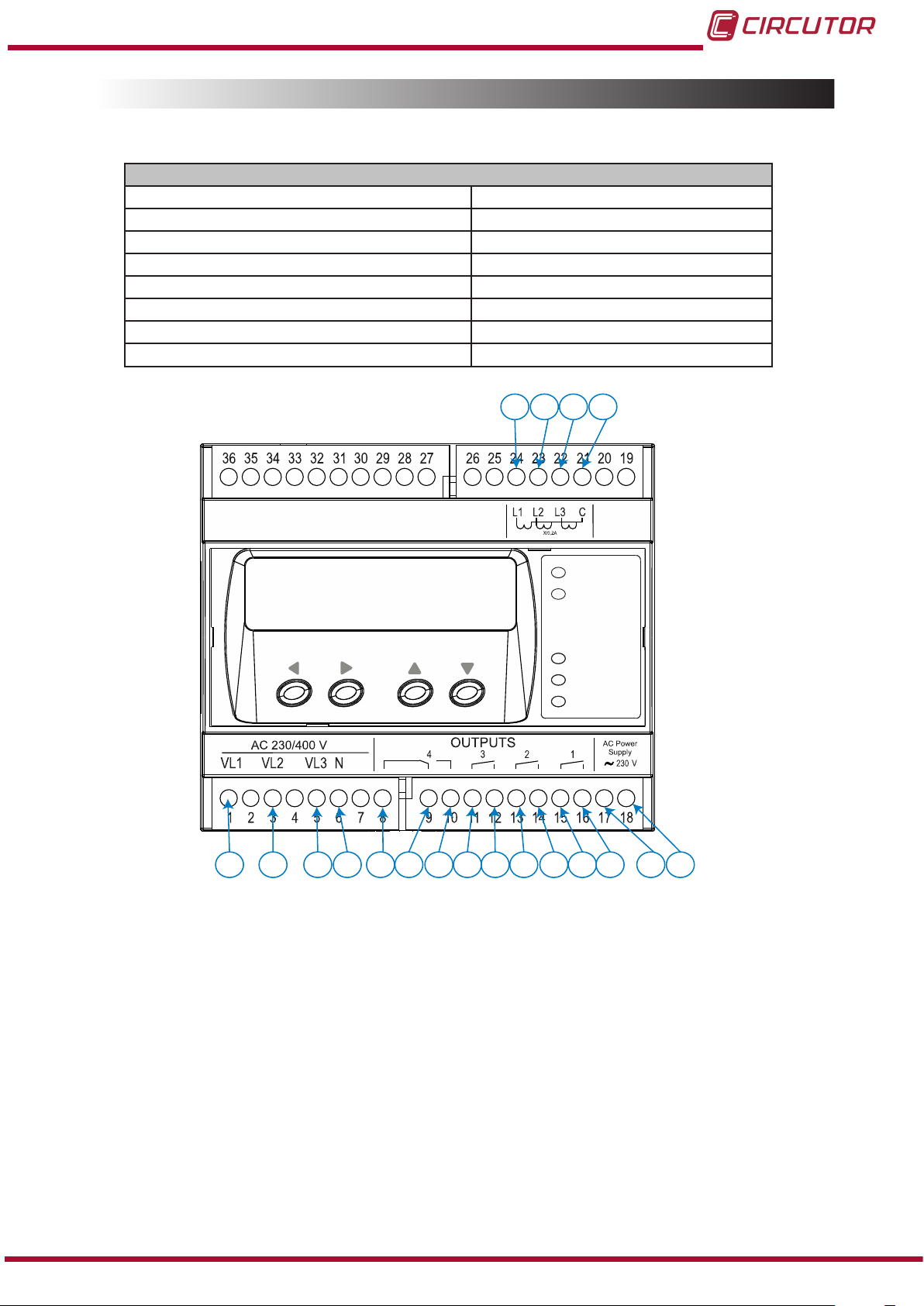
3.3.- UNIT TERMINALS
1: VL1, Voltage input L1 13, 14: Relay output 2
3: VL2, Voltage input L2 15, 16: Relay output 1
5: VL3, Voltage input L3 17: Auxiliary Power Supply
6: N, Voltage input neutral 18: Auxiliary Power Supply
8: Relay output 4, NC 21: COM, Common current inputs
9: Relay output 4, C 22: S1, Current input L3
10: Relay output 4, NO 23: S1, Current input L2
11, 12: Relay output 3 24: S1, Current input L1
Table 2:List of MDC-4 terminals
Unit terminals
24 2123 22
1
3 5 6 9
8
Figure 1:MDC-4 terminals�
10 11
12
13 14
CPU
OUT 4
MDC-4
OUT 3
OUT 2
OUT 1
15 16
17
18
Instruction Manual
9
Page 10
3.4.- CONNECTION DIAGRAM
MDC-4
CPU
OUT 4
OUT 3
OUT 2
OUT 1
Power
Supply
V
L1
L1
L2
L3
3P1
2P1 1P1
3P2
2P2 1P2
N
V
L2
V
L3
N
LOAD
Brown / Green
Grey / Pink
Green / White
Red / Blue
OUT 1OUT 2OUT 3OUT 4
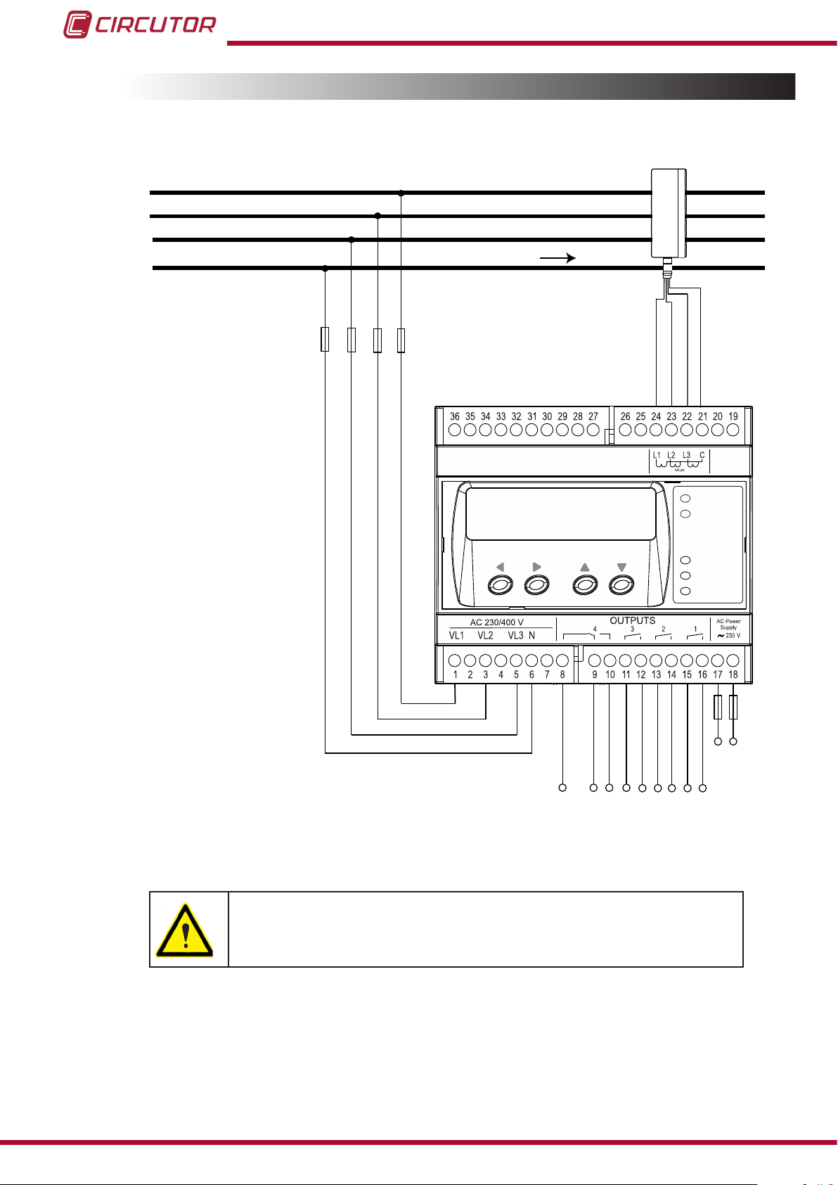
3�4�1�- Three-phase network measurement with a 4-wire connection�
MDC-4
Figure 2: Three-phase network measurement with a 4-wire connection�
The MC3 transformer secondary value is set to 0.250 A.
10
Instruction Manual
Page 11

MDC-4
CPU
OUT 4
OUT 3
OUT 2
OUT 1
Power
Supply
V
L1
L1
L2
L3
3P1
2P1 1P1
3P2
2P2 1P2
V
L2
V
L3
LOAD
Brown /Green
Grey / Pink
Green /White
Red /cBlue
OUT 1OUT 2OUT 3OUT 4
MDC-4
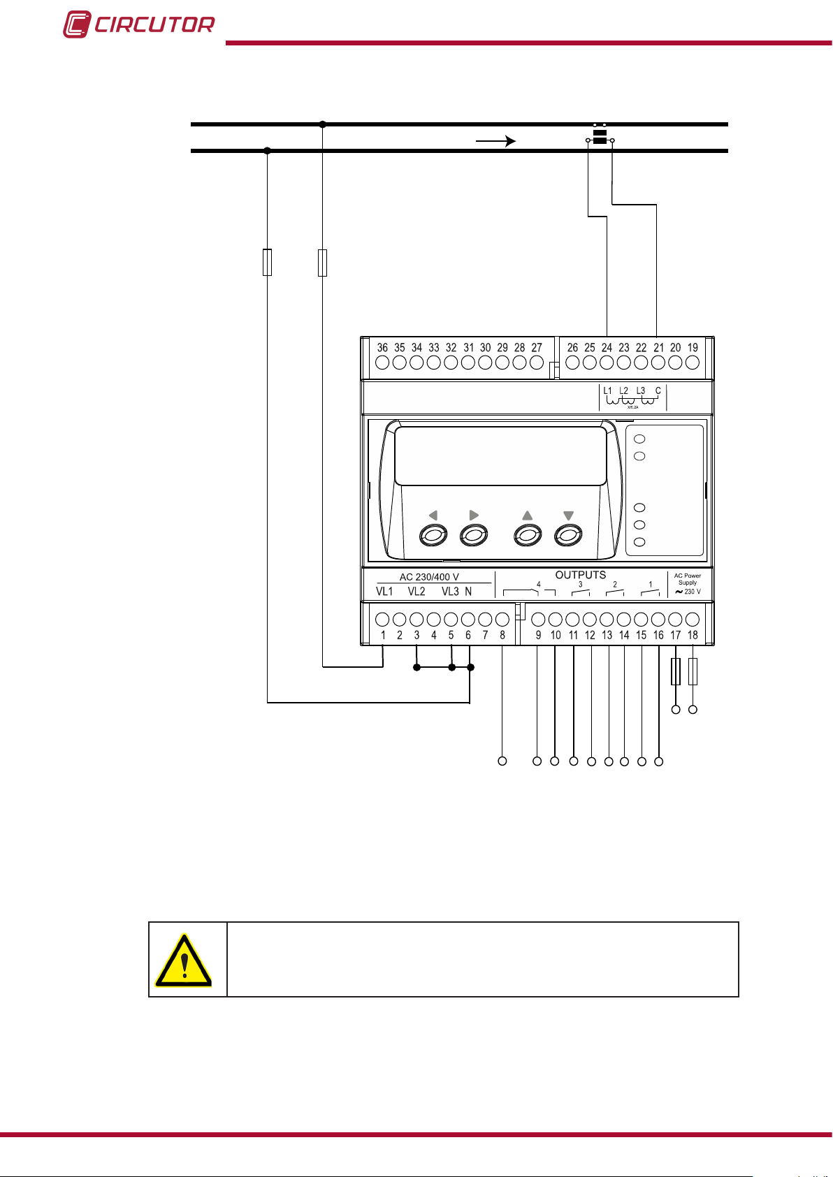
3�4�2�- Three-phase network measurement with a 3-wire connection�
Figure 3: Three-phase network measurement with a 3-wire connection�
The MC3 transformer secondary value is set to 0.250 A.
Instruction Manual
11
Page 12
3�4�3�- Single-phase network measurement�
MDC-4
CPU
OUT 4
OUT 3
OUT 2
OUT 1
Power
Supply
V
L1
L1
N
S1
S2
P1 P2
N
LOAD
OUT 1OUT 2OUT 3OUT 4
MDC-4
Figure 4: Single-phase network measurement�
12
The MC1 transformer secondary value is set to 0.250 A.
Instruction Manual
Page 13
MDC-4
4�- OPERATION
4.1.- OPERATING PRINCIPLE
The MDC-4 has been designed to control the maximum demand of an installation.
The unit is equipped with a power analyzer that measures electrical parameters at the connection point.
The unit calculates the maximum demand by scrolling window, do not need a sync pulse.
Depending on the unit's conguration and bearing in mind the calculated maximum demand,
the unit connects and disconnects the installation's electrical loads (which should not be priority
loads) in order to avoid exceeding the congured maximum power. Load connection or disconnection depends on the instantaneous level of maximum demand. This system proceeds to
disconnect the loads in accordance with the % maximum demand value measured.
The load control by level ensures that the user does not exceed the contracted power, which
generally implies having to pay high penalties. At the same time, it enables adjusting the contract to the real power each installation needs and managing the punctual disconnection of
some non-priority loads, which also results in important power savings in the electricity bill.
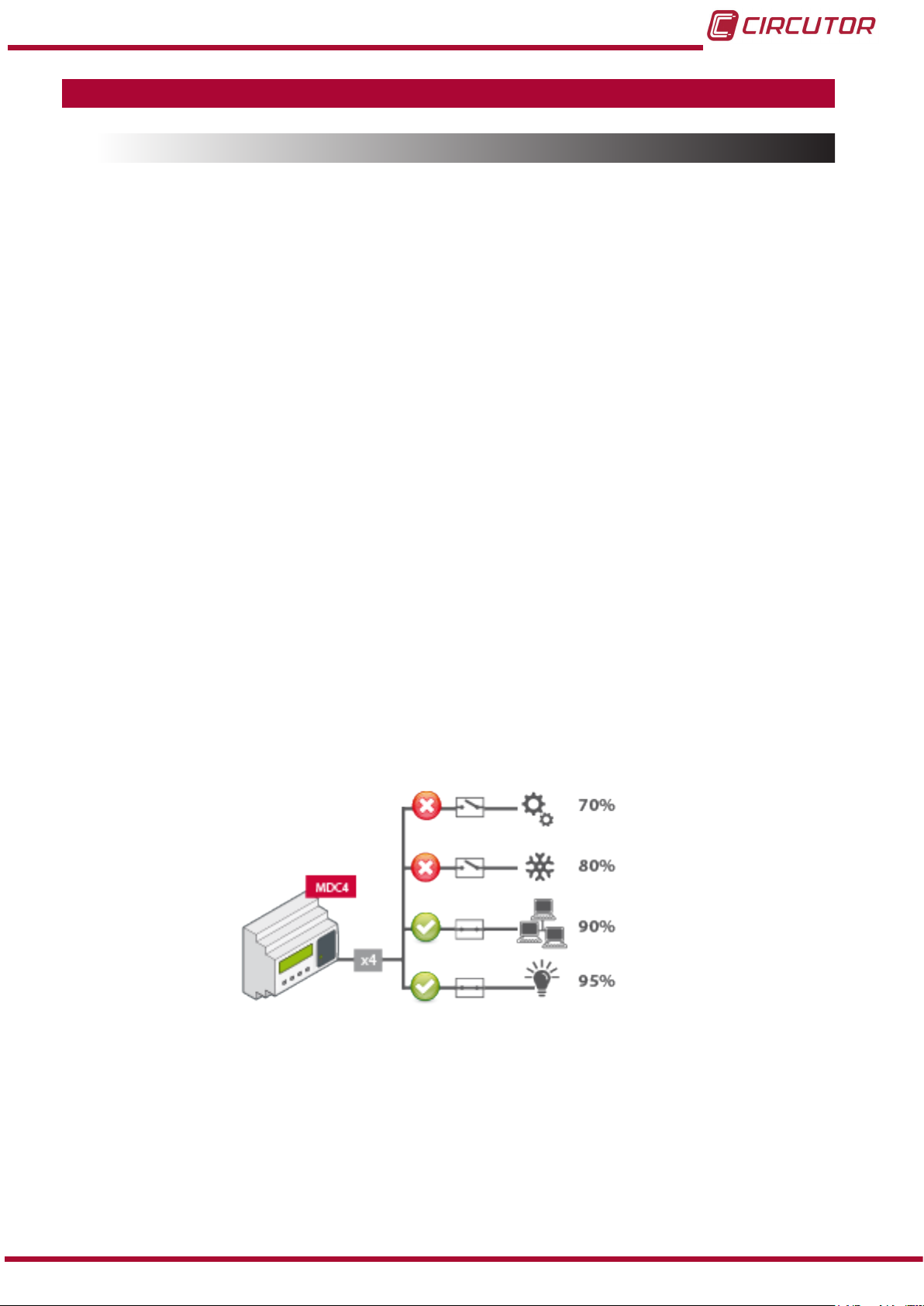
The unit is equipped with relay outputs for the management of up to 4 electrical loads or load
groups.
Example: Let's take an installation such as that shown in Figure 5, in which the level of each
of the output relays has been programmed as follows:
OUT1: 70% of the contracted power.
OUT2: 80% of the contracted power.
OUT3: 90% of the contracted power.
OUT4: 95% of the contracted power.
Instruction Manual
Figure 5: MDC-4 installation�
13
Page 14

The graph in Figure 6 shows the unit's response:
MDC-4
Figure 6: Graph with the response of the MDC-4
4.2.- PARAMETERS
The unit displays the electrical parameters shown in Table 3.
Table 3: MDC-4 measuring parameters�
Measuring parameter Units
Phase-neutral voltage V
Phase-phase voltage V
Current A
Active power W
Reactive power var
Apparent power VA
Cos φ φ
Active Energy kW·h
Current Date and Time -
Maximum demand parameters Units
Contracted power W / VA / mA
Instantaneous maximum demand W / VA / mA
Status of the output relays Maximum demand maximum value W / VA/ mA
The % of time that each output relay has been disconnected
Phases
L1-L2-L3
%
Total
III
14
Instruction Manual
Page 15

MDC-4
4.3.- KEYS FUNCTIONS
The MDC-4 has 4 keys that allow you to browse the various screens and program the unit.
Key functions on the measuring screens (Table 4):
Table 4: Key functions on measuring screens�
Key Short keystroke
Previous Measuring screen
Next Measuring screen
Long keystroke
(2 s)
Previous Maximum demand screen
Next Maximum demand screen
Key functions in the programming menus (Table 5):
Table 5: Function of keys�
Key Keystroke
Moves an editable digit
Go to programming screen
Increases the digits (0-9) or rotates between the different options.
Viewing the maximum demand maximum value.
Opens the programming menu
Opens the menu for programming the
current Date and Time.
4.4.- DISPLAY
The unit has a display of two lines each containing 20 characters, on which all the measuring
parameters are viewed, in addition to specic information for the control of the unit's relay outputs and the operation time of each of the loads.
Instruction Manual
15
Page 16

4.5.- LED INDICATORS
The MDC-4 unit features:
- A CPU LED, which indicates that the unit is working correctly when it ashes for 1 sec-
ond.
- Four LEDs (OUT 1, OUT 2, OUT 3, OUT 4), which indicate whether the load is connected or disconnected. If the LED is on, this indicates that the load is disconnected.
MDC-4
CPU
Figure 7: LED indicators�
OUT 4
OUT 3
OUT 2
OUT 1
16
Instruction Manual
Page 17

MDC-4
4.6.- DISPLAY IMPROVEMENTS
The unit has two types of screens for viewing:
Maximum demand screens. Measuring screens.
4�6�1�- Maximum demand screens�
Use keys and to browse the various screens.
The measuring screens are viewed by pressing the or keys.
Table 6: Maximum demand screens�
Screen Parameters (units)
Pc: Power contracted by the user (W or VA or mA).
Pd: Instantaneous calculated maximum demand
:60000 :56687
: : : :
(W or VA or mA).
o1 ...o4: Status of the output relays:
0 : Load connected
1 : Load disconnected
Holding down the key (2 seconds).
d max:
// ::
% % % %
Pd max: Maximum demand maximum value
Date and time when maximum value occurred.
It returns to the contracted power screen after 10
seconds.
The % of time that each output relay has been disconnected since it was connected to the unit or since
the last reset.
The % of time that each output relay has been disconnected and the maximum demand maximum value that can be reset in the programming menu.
Instruction Manual
17
Page 18

4�6�2�- Measuring screens�
Use keys and to browse the various screens.
The maximum demand screens are viewed by pressing the or keys.
Table 7: Measuring screens�
Screen Parameters (units)
MDC-4
vL12 vL23 vL31
519.3 519.8 519.6
vL1 vL2 vL3
299.9 300.0 300.0
a1 A2 a3
62.82 62.99 63.05
W1 W2 W3
18868 18893 18912
va1 va2 va3
-25 -81 -207
VL12: Phase-Phase Voltage L1-L2 (V).
VL23: Phase-Phase Voltage L2-L3 (V).
VL31: Phase-Phase Voltage L3-L1 (V).
VL1: Phase-Neutral Voltage L1 (V).
VL2: Phase-Neutral Voltage L2 (V).
VL3: Phase-Neutral Voltage L3 (V).
A1: Current L1 (A).
A2: Current L2 (A).
A3: Current L3 (A).
W1: Active power L1 (W).
W2: Active power L2 (W).
W3: Active power L3 (W).
VAr1: Reactive power L1 (Var).
VAr2: Reactive power L2 (Var).
VAr3: Reactive power L3 (Var).
COs1 COS2 COS3
-0.99 -0.99 -0.99
COs III VAIII
-0.99 -5
W III KW
56624 00000122.637
VA Iii AIII
0 0.00
DATE TIME
28/04/2014 14:08:54
COS 1: Cos φ L1
COS 2: Cos φ L2
COS 3: Cos φ L3
COS III: Cos φ III
VArIII: Reactive power III (Var).
W III: Active power III (W).
kWh: Active energy III (kWh).
VA III: Apparent power III (VA).
AIII: Current III (A).
Current date and time.
18
The active energy III value can be reset in the programming menu.
Instruction Manual
Page 19

MDC-4
4.7.- OUTPUT RELAYS
The unit has four relays (terminals 8, 9, 10, 11, 12, 13, 14, 15 and 16 in Figure 1) for connecting
and disconnecting the installation's loads, to ensure that the programmed maximum power is
not exceeded.
4.8.- PROGRAMMING
From the programming menu you can:
Program the current primary.
Program the maximum demand period.
Program the contracted power.
Delete the value for energy, the load disconnection times and the maximum demand
maximum value.
Congure the output relays.
The MDC-4 does not record the programming changes until all parameters have been programmed. If the unit is RESET before programming all parameters or no key is pressed for 60
seconds, the conguration will not be stored in the memory and relays return to its resting state
for a short time.
To enter the programming menu, hold the and keys for two seconds; the main programming screen will be displayed.
SETUP
Press the key to enter the rst programming screen.
4�8�1� Current primary
In this step the current primary value is pro-
Set P. A
063
When the desired value is shown on the screen, move onto the next digit by pressing the key
to modify the remaining values.
grammed.
Press the
currently ashing.
button to increase the digit that is
Maximum value: 250 A.
Minimum value: 1 A.
Press the key to access the next programming step.
Instruction Manual
19
Page 20

)
MDC-4
4�8�2� Selecting the maximum demand variable
In this step the variable for calculation the maxi-
SET PD V
P (W)
W: Active power.
VA: Apparent power.
mA: Current III
Press the key to access the next programming step.
4�8�3� Period of maximum demand integration
Set PD
015
When the desired value is shown on the screen, move onto the next digit by pressing the key
mum demand is programmed.
Press the
sible options:
In this step the maximum demand integration
period is programmed.
Press the
currently ashing.
button to select between the pos-
button to increase the digit that is
to modify the remaining values.
Maximum value: 60 minutes.
Minimum value: 1 minute.
Press the key to access the next programming step.
4�8�4� Contracted power
In this step the contracted power for the installa-
Set (W/v/m
_05000
When the desired value is shown on the screen, move onto the next digit by pressing the key
to modify the remaining values.
Maximum value: 500,000 (W /VA / mA)
Minimum value: 0 (W /VA / mA)
tion is programmed.
Press the
currently ashing.
button to increase the digit that is
20
Press key to access the next programming step.
4�8�5� Deleting the maximum demand maximum value�
In this step you select whether or not to delete
Clea PD mAX
NO
the maximum demand maximum value.
Press the
possible options: No or Yes.
button to select between the two
Instruction Manual
Page 21

out % Time
MDC-4
Press key to access the next programming step.
4�8�6� Deleting the energy value
In this step you select whether or not to delete
Clea Energy
NO
Press key to access the next programming step.
4�8�7� Deleting the output relay disconnection times�
Clea
the energy value.
Press the
possible options: No or Yes.
In this step you select whether or not to delete
the % of time that each output relay has been
disconnected.
button to select between the two
NO
Press key to access the next programming step.
4�8�8� Level of output relay no� 1
out1 Level (%)
Press the button to select between the two
possible options: No or Yes.
In this step you program the value (%) of contracted power from which the output relay is
disconnected.
75
Example: If OUT1 is programmed to 75%, when the maximum demand value reaches 75%
of the contracted power in the installation, output relay no.1 will be disconnected, thus disconnecting all the corresponding loads.
Press the key to increase the digit that is currently ashing.
When the desired value is shown on the screen, move onto the next digit by pressing the key
to modify the remaining values.
Maximum value: 99%.
Minimum value: 0 %.
Default: OUT1 : 75% , OUT2 : 80%, OUT3 : 90%, OUT4 : 95%
Press key to access the next programming step.
4�8�9� Hysteresis of output relay no� 1
The hysteresis value, i.e., difference between the
out1 Hyst (%)
05
relay connection and disconnection point, in %,
is programmed in this step.
Press the
currently ashing.
button to increase the digit that is
Instruction Manual
21
Page 22

)
MDC-4
When the desired value is shown on the screen, move onto the next digit by pressing the key
to modify the remaining values.
Maximum value: 99 %.
Minimum value: 0 %.
Press key to access the next programming step.
4�8�10� Delay in connecting output relay no� 1
In this step the delay in connecting the output
out1 Delay ON (s)
05
When the desired value is shown on the screen, move onto the next digit by pressing the key
to modify the remaining values.
relay is programmed.
Press the
currently ashing.
button to increase the digit that is
Maximum value: 99 seconds.
Minimum value: 0 seconds.
Press key to access the next programming step.
4�8�11� Delay in disconnecting output relay no� 1
In this step the delay in disconnecting the output
out1 Delay OFF (s
05
When the desired value is shown on the screen, move onto the next digit by pressing the key
to modify the remaining values.
Maximum value: 99 seconds.
Minimum value: 0 seconds.
Press key to access the next programming step.
relay is programmed.
Press the
currently ashing.
button to increase the digit that is
22
4�8�12� Status of the contacts for output relay no� 1
In this step the status of the output relay contact
out1 Contact
N.C.
N.C. normally closed.
N.O. normally open.
Press key to access the next programming step.
is selected.
Press the button to select between the two
possible options:
Instruction Manual
Page 23

MDC-4
In the next steps, the level, hysteresis and connection and disconnection delays are programmed, as well as the status of the contactors for output relays 2, 3 and 4.
The programming is identical to that of sections 4�8�8, 4�8�9, 4�8�10, 4�8�11 and 4�8�12�
4.9.- PROGRAMMING THE CURRENT DATE AND TIME
The MDC-4 does not record the programming changes until all parameters have been programmed. If the unit is RESET before programming all parameters or no key is pressed for 60
seconds, the conguration will not be stored in the memory.
To enter the programming menu for the current date and time, hold the and key for 2
seconds; the main programming screen will be displayed.
SETUP DATE
Press the key to enter the rst programming step.
4�9�1� Day
In this step the day of the month is programmed.
SET DAY
_8
When the desired value is shown on the screen, move onto the next digit by pressing the key
to modify the remaining values.
Press key to access the next programming step.
4�9�2� Month
SET MONTH
04
When the desired value is shown on the screen, move onto the next digit by pressing the key
Press the
currently ashing.
In this step the current month is programmed.
Press the
currently ashing.
button to increase the digit that is
button to increase the digit that is
to modify the remaining values.
Press key to access the next programming step.
Instruction Manual
23
Page 24

4�9�3� Year
MDC-4
SET YEA
2014
When the desired value is shown on the screen, move onto the next digit by pressing the key
to modify the remaining values.
Press key to access the next programming step.
4�9�4� Time
SET Hours
_4
When the desired value is shown on the screen, move onto the next digit by pressing the key
to modify the remaining values.
In this step the current year is programmed.
Press the
currently ashing.
In this step the current hour is programmed.
Press the
currently ashing.
button to increase the digit that is
button to increase the digit that is
Press key to access the next programming step.
4�9�5� Minutes
SET minutes
15
When the desired value is shown on the screen, move onto the next digit by pressing the key
to modify the remaining values.
Press key to access the next programming step.
NB: The unit does not automatically change from summer time to winter time.
In this step the minutes are programmed.
Press the
currently ashing.
button to increase the digit that is
24
Instruction Manual
Page 25

MDC-4
5�- TECHNICAL FEATURES
AC power supply
Rated voltage 110 ...240 V ~
Frequency 50 / 60Hz
Consumption 4...6 VA
Installation category CAT III 300 V
Voltage measurement circuit
Rated voltage (Un) 300 V P-N, 520 V P-P
Voltage measurement margin 5 ... 120% Un
Frequency measurement margin 45 ... 65Hz
Input impedance 400kΩ
Minimum measurement voltage (Vstart) 15 V
Installation category CAT III 300 V
Current measurement circuit
Nominal current (In) ... / 0.250 A
Current measurement margin 5 ... 100% In
Minimum measurement current (Istart) 10 mA
Installation category CAT III 300 V
Measurement accuracy
Accuracy in voltage measurement 0.5%
Accuracy in current measurement 0.5%
Accuracy in power measurement 1%
Relay outputs
Quantity 4
Maximum voltage, open contacts 250 ~
Maximum current 6 A
Maximum switching power 750 W
Electrical working life (250 VAC / 5A) 60x103 cycles
Mechanical working life 10x106 cycles
User interface
Display Alphanumeric LCD screen,
2 lines each containing 20 characters
Keys 4 keys
LED 5 LEDs
Environmental features
Operating temperature 0ºC ... +50ºC
Storage temperature -10ºC ... +60ºC
Relative humidity (non-condensing) 5 ... 95%
Maximum altitude 2,000 m
Protection degree
IP20
Mechanical features
Dimensions Figure 8
Weight 250 gr
Enclosure UL94-V0 self-extinguishing plastic
Instruction Manual
25
Page 26

105
MDC-4
65
44
5 25
90
Figure 8: Dimensions of the MDC-4�
35.5
45
Standards
UNE-EN 61010-1:2011 Safety requirements for electrical equipment for measurement, con-
trol and laboratory use -- Part 1: General requirements
UNE-EN 61000-4-2:2010 Electromagnetic compatibility (EMC) -- Part 4-2: Testing and measu-
rement techniques - Electrostatic discharge immunity test
UNE-EN 61000-4-3: 2007 Electromagnetic compatibility (EMC) -- Part 4-3: Testing and measu-
rement techniques - Radiated, radio-frequency, electromagnetic eld
immunity test
UNE-EN 61000-4-4: 2013
UNE-EN 61000-4-5: 2007
Electromagnetic compatibility (EMC) - Part 4-4: Testing and measurement techniques - Electrical fast transient/burst immunity test
Electromagnetic compatibility (EMC) -- Part 4-5: Testing and measurement techniques - Surge immunity test
Electromagnetic compatibility (EMC) -- Part 4-11: Testing and mea-
UNE-EN 61000-4-11:2005
surement techniques - Voltage dips, short interruptions and voltage
variations immunity tests
UNE-EN 61000-6-4:2007/A1:2011 Electromagnetic compatibility (EMC) -- Part 6-4: Generic standards -
Emission standard for industrial environments
65
26
Instruction Manual
Page 27

MDC-4
6�- MAINTENANCE AND TECHNICAL SERVICE
In the case of any query in relation to unit operation or malfunction, please contact the
CIRCUTOR, SA Technical Support Service.
Technical Assistance Service
Vial Sant Jordi, s/n, 08232 - Viladecavalls (Barcelona)
Tel: 902 449 459 ( España) / +34 937 452 919 (outside of Spain)
email: sat@circutor.es
7�- GUARANTEE
CIRCUTOR guarantees its products against any manufacturing defect for two years after the
delivery of the units.
CIRCUTOR will repair or replace any defective factory product returned during the guarantee
period.
• No returns will be accepted and no unit will be repaired or replaced if it is not accompanied by a report indicating the defect detected or the reason for the return.
•The guarantee will be void if the units has been improperly used or the storage, installation and maintenance instructions listed in this manual have not been
followed. “Improper usage” is de ned as any operating or storage condition contrary to the national electrical code or that surpasses the limits indicated in the
technical and environmental features of this manual.
• CIRCUTOR accepts no liability due to the possible damage to the unit or other
parts of the installation, nor will it cover any possible sanctions derived from a possible failure, improper installation or “improper usage” of the unit. Consequently,
this guarantee does not apply to failures occurring in the following cases:
- Overvoltages and/or electrical disturbances in the supply;
- Water, if the product does not have the appropriate IP classi cation;
- Poor ventilation and/or excessive temperatures;
- Improper installation and/or lack of maintenance;
- Buyer repairs or modi cations without the manufacturer’s authorisation.
Instruction Manual
27
Page 28
8�- CE CERTIFICATE
MDC-4
28
Instruction Manual
Page 29

MDC-4
Instruction Manual
29
Page 30

CIRCUTOR, SA
Vial Sant Jordi, s/n
08232 -Viladecavalls (Barcelona)
Tel.: (+34) 93 745 29 00 - Fax: (+34) 93 745 29 14
www.circutor.es central@circutor.es
 Loading...