

Page 1
MCB.P y MCB.T
Disyuntor + Control remoto
El MCB.P ó el son disyuntores que combinan
las funciones de magnetotérmico y contactor en un mismo
elemento. La versión MCB.T, incorpora además dos
contactos auxiliaresque indican el estado dela entrada de
control remoto y del magnetotérmico.
Tanto en la versión MCB.P como en la MCB.T, se
puede incorporar un contacto auxiliar para indicar el
disparo por magnetotérmico o por la actuación manual
sobre el disyuntor.
Como disyuntor tiene dos condiciones de disparo:
Disparo por sobrecalentamiento , retardado,
!
( protección de sobrecarga).
Disparo rápido, electromagnético ( protección contra
!
cortocircuito).
La función de control remoto actúa sobre los mismos
contactos que el magnetotérmico, garantizando la
desconexión encualquiera de loscasos y no permitiendo la
conexión, por control remoto, después de un disparo
manual o magnetotérmico
La función de control remoto se realiza
electromagnéticamente , aplicando una tensión de control,
de duración 20 ms, a los bornes ON ( bornes 1-3) y OFF
( bornes 2-3).
Incorpora una indicación óptica del estado del sistema
( rojo = ON , verde = OFF), indistintamente del origen del
disparo.
El mecanismotienetres posiciones, dependiendo dela
condición de disparo:
!
Posición RESET ( intermedia entre ON y OFF) .
Disyuntor abierto Disparo por sobrecarga o
cortocircuito, no permite rearme por control remoto.
Para la reconexión manual se debera llevar la
palanca a la posición OFF y subirla a la posición ON.
!
Posición ON.
remoto.
!
Posición OFF.
No permite control remoto
MCB.T
.
Disyuntor cerrado. Permite el control
Disyuntor abierto. Por disparo manual.
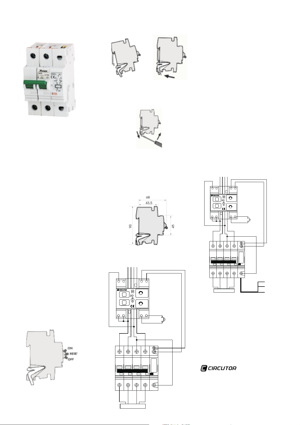
Instalación
El disyuntor puede ser montado en rail EN 50 022 (35 mm).
Para su instalación, colocar sobre el rail, ajustar a la
posición y fijar mediante el sistema de fijación (ver fig. 1 y
2)
fig. 1 fig. 2
El equipo puede ser extraido fácilmente, si es necesario,
con la ayuda de un destornillador, tal como se muestra en
la fig. 3
Conexiones
El MCB dispone de bornes con cabezal combinado, tanto
en entrada com en salida, de sección1a25mm para
cables trenzados como para conductores rígidos.Par de
apriete aconsejado: 2 Nm.
El módulo de control dispone de bornes de contacto,y
la sección máxima del cable que pueden acoger es de
2
2
2,5 mm . El par de apriete aconsejado es de 0,8 Nm.
.
Esquema conexión MCB.P con relé diferencial
WRKRT-25T
L3L2L1N
2 1A1
0.5
0.3
0.75
0.1
1
0.02
T
R
Un230VUn230V type WRKRT-25Ttype WRKRT-25T
COMA2
T
E
S
T
R
E
S
E
T
s
DELAY
0.5
0.3
1
0.1
30.03
POWER
A
R1 R2
RESET
EXTERNO
2
1
MCB.T
El modelo , incorpora en el módulo de control
remoto dos contactos auxiliares, libres de tensión,
mediante una manguera de tres hilos ( blanco , verde ,
marrón) referidos aun mismopuntocomún:
Cable , común.
!
Cables y (información del control remoto)
!
ON contacto cerrado (control remoto ON )
OFF contacto abierto (control remoto OFF )
Cables y ( información de la palanca ON
!
RESET-OFF)
ON contacto cerrado ( palanca en ON )
OFF contacto abierto ( palanca en RESETo OFF)
Cables y (Informacióndisparopordiferencial
!
o magnetotérmico)
ON contacto cerrado ( No hay disparo )
OFF contacto abierto (Disparo por diferencial o
magnetotérmico)
Tener en cuenta que el contacto del control remoto
indica las órdenes recibidas independientemente del
estado del magnetotérmico ( posición ON , OFF, RESET).
El MCB.T sólo será controlable mediante señales
del tipo impulso (duración 20 ms ). El no respetar
esta consideración dañará irreversiblemente el
módulo de control remoto. El MCB-T sólo será
aplicable a relés diferenciales de la serie WRKRT-25T.
Los contactos auxiliares permiten una corriente
máxima permanente de 0.5 A a una tensión de 230 V c.a.
Esquema conexión MCB.T con relé diferencial
WRKRT-25T
Un230VUn230V type WRKRT-25TtypeWRKRT-25T
Características técnicas
Tensión de control
Corriente de control nominal
Frecuencia
Duración pulso on
Número de conmutaciones
Frecuencia de cambio
Bornes
Protección (
MCB.T
blanco
verde blanco
marrón blanco
marrón verde
L3L2L1N
2 1A1
0.5
0.3
0.1
0.75
1
0.02
T
s
E
S
T
R
COMCOMA2
T
R
E
S
POWER
E
T
CARGA
0.1
0.3
0.5
R1 R2
DELAY
1
30.03
A
RESET
EXTERNO
2
1
3
Contactos auxiliares
(Blanco). COMÚN
(Marrón) Estado
magnetotérmico
(Verde) Estado
diferencial
210 V.....240 V c.a.
1.5 A
50Hz/60Hz
>20 ms
>20.000
12/min max.
protegidos según
DIN VDE 0106,parte 100
DIN 40 050 ) IP 20
CARGA
Vial Sant Jordi, s/n
08232 Viladecavalls
3
Barcelona (Spain)
Tel. (+34) 93 745 29 00
Fax 93 745 29 13 (export)/ 93 745 29 05
(+34)
e-mail: central@circutor.es
web: www.circutor.com
Cód: M98138201-20-03A
Page 2
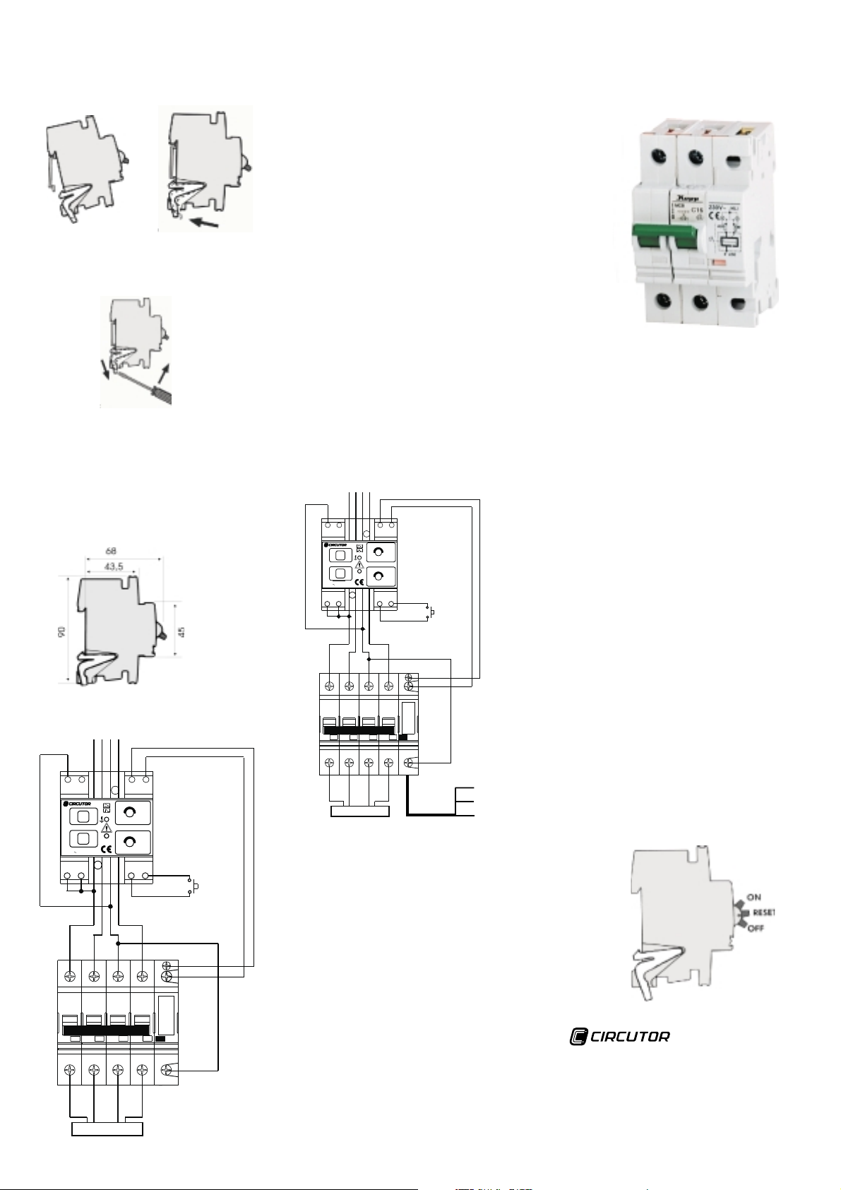
Installation
The breaker can be mounted in any position on an EN 50
022 (35 mm wide) top-hat rail..
To install, place the MCB.P with remote control mechanism
on the rail, adjust to the desired position, then lock the rapid
fastening system (see fig.1y2)
fig. 1 fig. 2
The unit caneasily be removed from its mounting position
retrospectively, if required, by releasing the rapid fastening
system with a screwdriver (see fig. 3)
fig. 3
Connection
The MCB is equipped with open, combination-type box
terminals with multo-slot screws on the input and output
sides, permitting the connection of fine-strand or solid
conductor with a cross section of 1-25 mm . Specified
tightening torque, 2Nm.
The remote control mechanism is provided with screw
terminals, suitable for the connection of conductors up to
max. 2.5 mm .Specified tightening torque, 0.8 Nm.
2.
2
.
MCB.P - WRKRT-25T diagramm connection
L3L2L1N
2 1A1
0.50.5
0.3
0.75
0.1
1
0.02
T
E
S
T
T
R
E
S
R
E
T
typeWRKRT-25Ttype WRKRT-25T
Un230VUn230V
COMA2
s
DELAY
0.5
0.3
1
0.1
30.03
POWER
A
R1 R2
EXTERNAL
RESET
2
1
MCB.T
The MCB.T model incorporates two free-voltage
auxiliary contacts in the remote control module.
connector (white, green and brown cables) referred to a
same common point:
White cable: common
!
!
Green white
control state.
!
Brown white
lever position ON RESET-OFF.
!
Brown green
earth leakage trip.
commands regardless the circuit breaker state (ON, OFF,
RESET position).
signals (20 ms of duration), otherwise, the control
remote module might suffer irreparable damage. The
MCB.T will only be applicable to WRKRT-25T series
differential relays.
Rated voltage
Exciting current
Frequency
Exciting current duration >
Nr. of operations >
Switching changes
Connecting terminals
Type of protection
These contacts leave through a tree-cable
and cables: information about the remote
ON: closed contact (remote control ON )
OFF: open contact (remote control OFF )
and white cablse: information about the
ON: closed contact (lever at ON )
OFF: open contact (lever at RESET or OFF)
and cables: information of overcurrent or
ON: closed contact (No trip)
OFF: open contact (earth leakage or overcurrent trip)
Take into account that:
The remote control contact indicates the received
The MCB.T must be only controlled by pulse type
MCB.T - WRKRT-25T diagramm connection
L3L2L1N
2 1A1
0.3
0.5
0.1
0.75
1
0.02
T
s
E
S
T
R
Un230VUn230V type WRKRT-25TtypeWRKRT-25T
COMA2
T
R
E
S
E
T
LOAD
DELAY
0.3
0.5
0.1
1
POWER
30.03
A
2
1
3
EXTERNAL
RESET
Auxiliary contacts
(White) COMMON
(Brown )
ON-OFF-
RESET level
(Green ) Remote
control state inf.
state inf.
R1 R2
Technical Data:
210 V ....230 V a.c.
1.5 A
50Hz/60Hz
20 ms
20.000
max. 12/min
Shock protected to
DIN VDE 0106,part 100
DIN 40 050 IP 20
MCB.P and MCB.T
Miniature circuit breaker
with remote-control
The MCB.PorMCB.T are circuit breakersthat provides
a combination of overcurrent protection and contactor
functions into the same element. The MCB.T version
incorporates two auxiliary contactsthat indicatethe state of
the remote control input and of the overcurrent protection.
For theMCB.Pand MCB.T version, an auxiliarycontact
can be added to the instrument for the indication of an
overcurrent trip or a manual action over the circuit breaker.
As a circuit breaker operation, two trip conditions are
set:
Delayed thermal trip (overload protection).
!
Quick electromagnetic trip (short-circuit protection).
!
The remote control function operates over the same
contacts that the circuit breaker does, guarantying the trip
for anycase,and avoiding a remote controlconnectionafter
a manual or overcurrent trip occurrence.Theremote control
function is electro-magnetically carried out by the
application of an excitation voltage during 20 ms between
terminals ON (terminals 1-3) and OFF (terminals 2-3).
A built-in optical indication permits to know the system
state (red = ON, green = OFF) regardless the trip cause.
The protection set has three different positions
according to the trip condition:
!
RESET position (intermediate between ON & OFF).
Open circuit breaker. Trip due to overload or short-circuit
event; remote control switchingon action not allowed. Fora
manual switching on, the lever must be moved to the OFF
position and then raised to the ON position.
!
ON position.
allowed.
!
OFF position.
control is not allowed.
Closed circuit breaker. A remote control is
Open circuit breaker. Manual trip.A remote
LOAD
Vial Sant Jordi, s/n
3
08232 Viladecavalls
Barcelona (
Tel. (+34) 93 745 29 00
Fax 93 745 29 13 (export)/ 93 745 29 05
(+34)
e-mail: central@circutor.es
web: www.circutor.com
Spain)
Cód: M98138201-20-03A
 Loading...