

Page 1
LM50-TCP+
UNIT CENTRALIZATOR LM50-TCP+
The LM50-TCP+ is an instrument equipped with 50
voltage-free digital inputs. Through these inputs, using
a master communications software, the user can detect
the logical state of the inputs (open or closed contact),
or otherwise know the number of impulses or
manoeuvres received by an outside impulses emitter
(energy, water, gas meter, etc).
The recorded parameters are shown in the following
variables table (see section 2.3.-).
The purpose of this document is to be a user and operation
manual for LM50-TCP+. It can be downloaded from
CIRCUTOR's website:
Before performing any maintenance operations,
connection modifications, repairs, etc., the unit
must be disconnected from the power supply. If
protection system, remove the unit from service. The design of
the unit makes it easy to replace in the event of a fault.
you suspect an operational fault in the unit or in its
www.circutor.es
1.- DESCRIPTION
The electronic meters have an impulses output that is
proportional to the recorded power. The LM50-TCP+ is
a unit centralizator, equipped with 50 digital inputs
(opto-coupled) for reading the impulses coming from
the meters for electric power, water, gas, etc. The
value of these impulses is associated with 50 memory
records, stored in a non-volatile memory.
Each record has 32 bits (4 bytes), so it can be counted
up to FFFF FFFF hexadecimal, i.e., a total of
4,294,967,295 impulses. When a memory record
reaches this value, the meter is reset back to zero.
The minimum duration of the status change of the
digital input must be of 50 ms. The minimum time
between two successive impulses must also have a
minimum duration of 50 ms. This represents a
maximum sampling frequency of 10 Hz.
2.- COMMUNICATION
For reading or writing the 50 internal records, the
device is equipped with a 10BaseT/100BaseTX selfdetectable Ethernet communication port. The device
has an internal webpage from which the user can
define the network protocol used to communicate with
the management software.
The network protocols that are available and integrated
in the device are: UDP, TCP and Modbus/TCP and to a
completely configurable port (with the exception of
Modbus/TCP that uses port 502 by default).
The device attends to the Modbus/RTU communication
protocol (in TCP and UDP mode) and Modbus/TCP.
In addition to the Ethernet connection, the device is
fitted with an RS485 expansion bus, in order to behave
like an RS485/Ethernet gateway. A maximum of 31
Modbus/RTU slave devices can be connected to this
bus.
2.1.- Ethernet addressing
As the connection from the device to the master
communication system is made using an IP
connection, the addressing parameters must be set.
The setup mode will either by the assignment of a fixed
IP, or by setting a DHCP name.
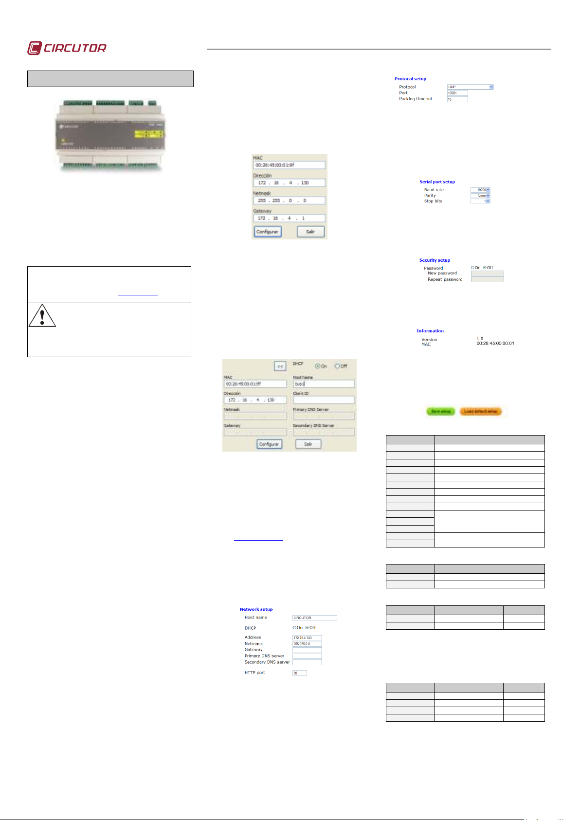
2.1.1.- Ethernet addressing assignment
For setting up the IP addressing in any of the available
formats, run program IPSetup.exe that is supplied with
the equipment.
2.1.2.- Fixed IP assignment
To assign the fixed IP address enter the MAC address
shown on the indelible side label attached to the device
with a format of the type 00:26:45:XX:XX:XX. In the
Address field enter the IP address; do the same with the
(Netmask) and the (Gateway) port if necessary. After
entering the device settings, press “Setup” to send the
configuration to the equipment.
2.1.3.- DHCP IP assignment
To assign the DHCP name, activate this option by
means of the upper right-hand date and select On.
Once the setup fields have been enabled, enter the
MAC address that can be seen on the indelible side
label attached to the device with a format of the type
00:26:45:XX:XX:XX. In the Address field, enter a
temporary free IP address that is within the working
range of your computer. In Host Name enter the DHCP
name to be assigned to the machine. Optionally, the
user may even set the parameters of the ClientID field.
The device's default VendorID is circutor.
2.2.- Setup webpage
Once connected to the Local Area Network (LAN), and
the IP address or the DHCP name have been set up,
the machine has an internal webpage where all the
parameters relating to the network protocols and
communication speeds of the RS485 bus, can be set
up. To access this internal webpage, it is sufficient to
use a conventional Internet browser and enter the IP
address or the name assigned to the device (for
example
http://172.16.4.130
)
2.2.1.- IP address or DHCP name
By means of the internal webpage, the user can make
any change to the DHCP name or to the IP address
previously assigned to the device, and even change the
http setup access port.
2.2.2.- Network protocol
The equipment can be connected to the master
communications system by means of three types of
network protocol and to a configurable (TCP, UDP or
Modbus/TCP) port. In the case of the Modbus/TCP
protocol the modification of the port will remain
disabled, staying fixed at 502.
2.2.3.- Setup of the RS485 serial bus
The communications parameters of the RS485
expansion bus are totally configurable for transmission
speed (from 4800 bps to 115.2 kbps), parity (none, odd
or even) and stop bit (1 or 2). Only devices that work
with the Modbus/RTU protocol and a peripheral
number other than 1 can connect to this slave port.
2.2.4.- Setting the setup password
Password can be activated to enable the edition
password. In case to use, the access user is “admin”
and the setup password introduced.
2.2.5.- Device information
The firmware version and the machine address of the
device are shown on the lower part.
2.2.6.- Save changes
Once any change has been made to the
aforementioned sections, the information must be
saved using the “Save Setup” option. If you wish to
return to the default setup, select “Load default setup”.
2.3.- Modbus memory map
Modbus Address Variable
0000 Bits 15…0 – Status of inputs 1 to 16 (Binary)
0001 Bits 15…0 – Status of inputs 17 to 32 (Binary)
0002 Bits 15…0 – Status of inputs 33 to 48 (Binary)
0003 Bits 15…0 – Status of inputs 49 to 50 (Binary)
0080 Value of the meter assigned to input 1
0082 Value of the meter assigned to input 2
0084 ... .... 00DE 2 bytes per input value (from 2 to 48)
00E0 Value of the meter assigned to input 49
00E2 Value of the meter assigned to input 50
0578
0579
057A
2710
2711
Shows the version of the equipment. The format
is the following “V1.10” in ASCII values and the
last byte is always 0.
Serial number, always starts with
900 XXX XXX
2.3.1.- Modbus functions
(HEX) function Description
03 / 04 Reading of input records
10 Writing of several records
2.3.2.- Reading of Modbus records
(HEX) function
AAAA Reading starting address 0082
BBBB Number of records 0002
Example of the reading command relating to the value of the
record belonging to digital input 2 (0082Hex).
TX: 01 04 AAAA BBBB CRC
RX: 01 04 04 0000 0000 CRC
2.3.3.- Writing of Modbus records
(HEX) function Description
AAAA Reading starting address 0082
BBBB Number of records 0004
CC Number of bytes sent 08
DDDD DDDD Value of each record 0000 0064 …
Example of writing command for digital inputs 2 and 3,
recording a value of 100 and 200 in each of them (0000 0064
and 0000 00C8 Hexadecimal)..
TX:
RX: 01 10 0082 0004 CRC
Description Example
Example
01 10 AAAA BBB B CC DDDDDDDD DDDDDDDD
CRC
M98231601-03-11A.doc1A
Page 2
LM50-TCP+
3.- MBUS testing software
The LM50-TCP+ device is supplied with MSDOS
software which has the main purpose of testing the
communications with the device. The software, just
like the device setup, can work with different
networking protocols and to a specific port. Its name
is MBUS.
To use the program, save the mbus.exe file to a
folder that can be accessed from MSDOS and use
this application paying attention to the networking
protocol requirements set up in the device.
3.1.- Warnings
To start communication with the LM50-TCP+ device,
ensure that the equipment is powered on and
connected to the Local Area Network (LAN) from
which the sending of the Modbus frames will be
made. Similarly, check that your computer or
Ethernet network does not have a firewall or a
security system that could prevent the said network
protocols and the ports set up in the device from
working.
Below, examples are shown in italics of the sending
of Modbus commands using the different network
protocols (UDP/TCP/ModbusTCP).
4.- TECHNICAL SPECIFICATIONS
Power circuit:
- Single-phase (phase – neutral) A1 – A2 :
- Frequency:
- Maximum consumption:
- Working temperature:
- Water content (non-condensing):
Mechanical features:
- Case material:
- Degree of protection of the equipment:
- Dimensions (mm):
- Weight:
- Maximum operating height:
Network interface:
- Type:
- Connector:
- Network protocols:
Serial interface:
- Type:
- Transmission speed (configurable):
- Data bits:
- Parity:
- Stop bit
3.2.- UDP Communications (u)
With the LM50-TCP+ device set up for the UDP
protocol and a specific port (in the example 10001), an
example of sending the Modbus command is shown
below.
Example of the reading command relating to the value of the
record corresponding to digital input 2 (0082Hex).
c:\>mbus u172.16.4.130 p10001 010400820002
010400820002 CRC
01040400000000 CRC 100.00%
where: 172.16.4.130 LM50-T CP+ IP address
10001 LM50-TCP+ UDP port
100% Response OK
3.3.- TCP communication (t)
With the LM50-TCP+ device has been set up for the
TCP protocol and a specific port (in the example
10001), an example of sending the Modbus command
is shown below.
Example of the reading command relating to the value of the
record corresponding to digital input 2 (0082Hex).
c:\>mbus t172.16.4.130 p10001 010400820002
010400820002 CRC
01040400000000 CRC 100.00%
85…265 VAC / 120…374 VDC
47…63 Hz
5 …8 V·A
-10 …..+ 60 ºC
5 ….. 95%
UL94 - V0 self-extinguishing plastic
IP 20
158.2 x 57.75 x 90 mm (8 modules)
320 grams
2,000 metres
Ethernet 10BaseT / 100BaseTX self-detectable
RJ45
TCP / UDP / MODBUS TCP / HTTP
RS485 three wires (A/B/S)
4800, 9600, 19,200, 34,800, 57,600, 115,200 bps
8
No parity, odd, even
1 / 2
Safety:
where: 172.16.4.130 LM50-T CP+ IP address
10001 LM50-TCP+ TCP port
100% Response OK
3.4.- Modbus/TCP communication (x)
With the LM50-TCP+ device set up for the
Modbus/TCP protocol and port 502, an example of
sending the Modbus command is shown below.
Example of the reading command relating to the value of the
record corresponding to digital input 2 (0082Hex).
c:\>mbus x172.16.4.130 p502 010400820002
1F1000000006010400820002 CRC
1F100000000701040400000000 CRC 100.00%
where: 172.16.4.130 LM50-T CP+ IP address
502 Modbus/TCP por t
100% Response OK
3.5.- Power Studio Scada software
CIRCUTOR provides the PowerStudio software,
from which all the data coming from the LM50-TCP+
device can be viewed in real-time. Download it from
www.circutor.com.
Inputs features:
- Type:
- Maximum activation current:
- Minimum Ton / Toff:
LED symbols:
- Power
- RX in blinking
- TX in blinking
- FULL/HALF (Ethernet)
- ACTIVITY
- 10M/100M
- LINK
Installation category Class III / EN61010 Protection against electric shock with class II
double insulation. The equipment must be connected to a power supply circuit protected with
type gl fuses as per IEC 269 or type M, with values comprised between 0.5 and 1A. It must
be fitted with a circuit breaker switch or an equivalent device, in order to be able to
disconnect the equipment from the power supply grid. The minimum section of the power
supply cable shall be of 1mm
Standards:
IEC 60664, VDE 0110, UL 94, EN61010-1, EN55011, EN 61000-4-2, EN 61000-4-3,
61000-4-11, EN 61000-6-4, EN 61000-6-2, EN 61000-6-1, EN 61000-6-3, EN 61000-4-5
EC
Free of opto-insulated voltage (dry contact)
50 mA
50 ms / 50 ms
Equipment power supply and CPU activity
Activity in the receipt of RS485 frames
Activity in the emission of RS485 frames
Green: Full Duplex connection / Yellow: Half Duplex
Activity in the Ethernet port
Green: Speed 100 Mbps / Yellow: 10 Mbps
A physical connection has been made with the Ethernet
network
2
.
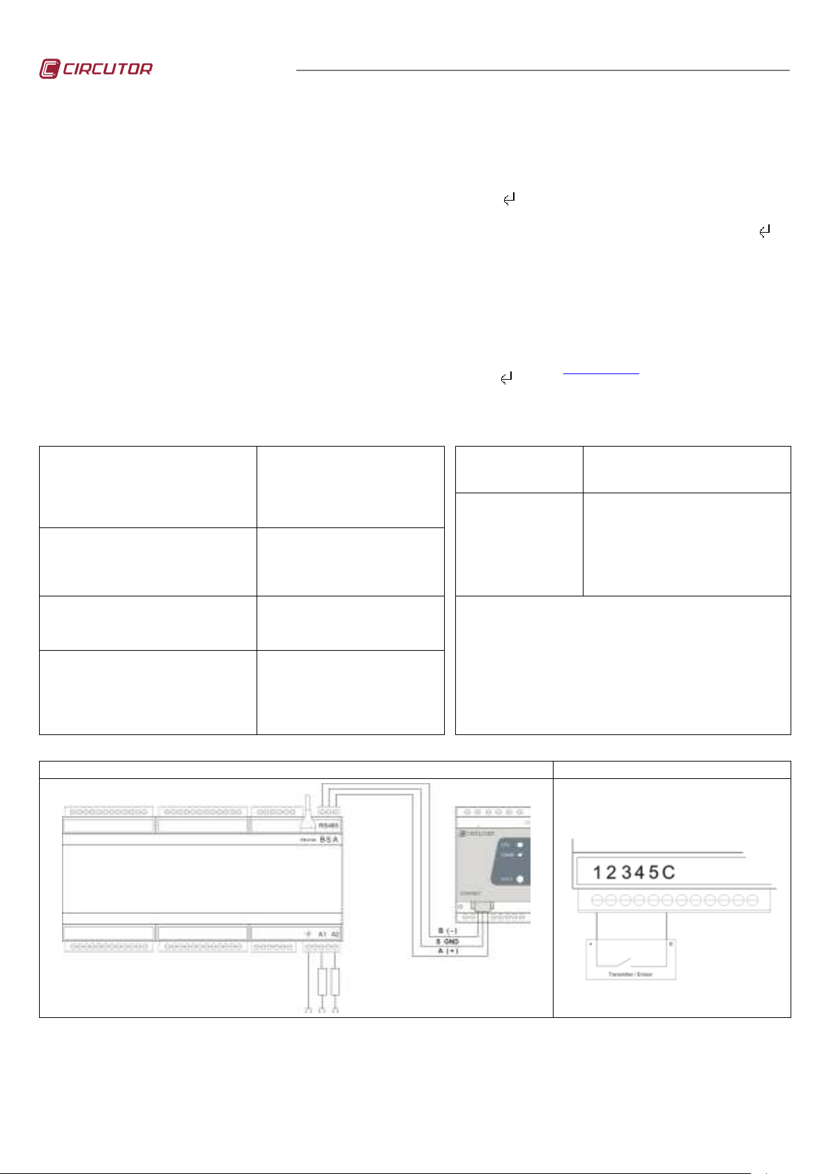
5.- CONNECTIONS
DETAIL OF POWER SUPPLY AND RS485 CONNECTIONS (SLAVE DEVICES) DETAIL OF DIGITAL INPUT 1 ACTIVATION
6.- TECHNICAL SERVICE
If you have any doubts about the operation of the unit or any malfunction, contact our service staff at CIRCUTOR, SA
CIRCUTOR, SA - Technical Assistence
Vial Sant Jordi, s/n
08232 – Viladecavalls (Barcelona), SPAIN
Tel: (+34) 93 745 29 00
email:
sat@circutor.es
M98231601-03-11A.doc1A
 Loading...