

CIRCUTOR CEM-C31-T1, CEM-C31-T1-MID, CEM-C31-485-T1, CEM-C31-485-T1-MID, CEM-C31-485-DS Instruction Manual
...Page 1
Multifunctional energy meter
CEM-C31-T1, CEM-C31-T1-MID
CEM-C31-485-T1, CEM-C31-485-T1-MID
CEM-C31-485-DS, CEM-C31-485-DS-MID
INSTRUCTION MANUAL
(M017B01-03-20B)
Page 2

CEM-C31
2
Instruction Manual
Page 3
CEM-C31
SAFETY PRECAUTIONS
Follow the warnings described in this manual with the symbols shown below.
DANGER
Warns of a risk, which could result in personal injury or material damage.
ATTENTION
Indicates that special attention should be paid to a speci c point.
If you must handle the unit for its installation, start-up or maintenance, the following
should be taken into consideration:
Incorrect handling or installation of the unit may result in injury to personnel as well as damage
to the unit. In particular, handling with voltages applied may result in electric shock, which may
cause death or serious injury to personnel. Defective installation or maintenance may also
lead to the risk of re.
Read the manual carefully prior to connecting the unit. Follow all installation and maintenance
instructions throughout the unit’s working life. Pay special attention to the installation standards of the National Electrical Code.
Refer to the instruction manual before using the unit
In this manual, if the instructions marked with this symbol are not respected or carried out correctly, it can
result in injury or damage to the unit and /or installations.
CIRCUTOR, SA reserves the right to modify features or the product manual without prior noti cation.
DISCLAIMER
CIRCUTOR, SA reserves the right to make modi cations to the device or the unit speci ca-
tions set out in this instruction manual without prior notice.
CIRCUTOR, SA on its web site, supplies its customers with the latest versions of the device
speci cations and the most updated manuals.
www.circutor.com
CIRCUTOR, recommends using the original cables and accessories that are
supplied with the device.
Instruction Manual
3
Page 4

CEM-C31
CONTENTS
SAFETY PRECAUTIONS ���������������������������������������������������������������������������������������������������������������������������������������3
DISCLAIMER ����������������������������������������������������������������������������������������������������������������������������������������������������������3
CONTENTS ������������������������������������������������������������������������������������������������������������������������������������������������������������� 4
REVISION LOG �������������������������������������������������������������������������������������������������������������������������������������������������������5
SYMBOLS ��������������������������������������������������������������������������������������������������������������������������������������������������������������� 5
1�- VERIFICATION UPON RECEPTION ����������������������������������������������������������������������������������������������������������������� 6
2�- PRODUCT DESCRIPTION �������������������������������������������������������������������������������������������������������������������������������� 6
3�- DEVICE INSTALLATION ����������������������������������������������������������������������������������������������������������������������������������� 7
3�1�- PRELIMINARY RECOMMENDATIONS ����������������������������������������������������������������������������������������������������7
3�2�- INSTALLATION �����������������������������������������������������������������������������������������������������������������������������������������8
3�3�- DEVICE TERMINALS �������������������������������������������������������������������������������������������������������������������������������� 8
3�3�1� MODEL CEM-C31-T1 �������������������������������������������������������������������������������������������������������������������������8
3�3�2� MODEL CEM-C31-485-T1 ������������������������������������������������������������������������������������������������������������������ 9
3�3�3� MODEL CEM-C31-485-DS �����������������������������������������������������������������������������������������������������������������9
3�4�- CONNECTION DIAGRAM ����������������������������������������������������������������������������������������������������������������������� 10
3�5�- CONNECTIONS ��������������������������������������������������������������������������������������������������������������������������������������� 11
4�- OPERATION ���������������������������������������������������������������������������������������������������������������������������������������������������13
4�1�- BUTTON FUNCTIONS ����������������������������������������������������������������������������������������������������������������������������13
4�2�- DISPLAY ��������������������������������������������������������������������������������������������������������������������������������������������������14
4�3�- LED INDICATORS ����������������������������������������������������������������������������������������������������������������������������������� 15
4�4�- IMPULSE OUTPUT (CEM-C31-T1 and CEM-C31-485-T1 models) ������������������������������������������������������15
4�5�- DIGITAL INPUT (CEM-C31-485-DS) ������������������������������������������������������������������������������������������������������� 16
5�- DISPLAY ����������������������������������������������������������������������������������������������������������������������������������������������������������17
5�1�- DISPLAY IN STANDBY MODE ����������������������������������������������������������������������������������������������������������������17
5�2�- DISPLAY IN READING MODE ����������������������������������������������������������������������������������������������������������������20
5�3�- INSTANTANEOUS VALUE DISPLAY ������������������������������������������������������������������������������������������������������21
5�4�- PARTIAL ENERGY DISPLAY ������������������������������������������������������������������������������������������������������������������ 23
5�5�- IMPULSE COUNT DISPLAY (CEM-C31-485-DS) ����������������������������������������������������������������������������������� 26
5�6�- MANUFACTURER INFORMATION SCREEN ����������������������������������������������������������������������������������������� 27
6�- CONFIGURATION ����������������������������������������������������������������������������������������������������������������������������������������29
6�1�- RELEVANT PARAMETERS CONFIGURATION ������������������������������������������������������������������������������������� 29
6�1�1� VOLTAGE PRIMARY TRANSFORMATION RATIO ������������������������������������������������������������������������� 29
6�1�2� VOLTAGE SECONDARY TRANSFORMATION RATIO ������������������������������������������������������������������� 30
6�1�3� CURRENT PRIMARY TRANSFORMATION RATIO ������������������������������������������������������������������������30
6�1�4� CURRENT SECONDARY TRANSFORMATION RATIO ������������������������������������������������������������������ 31
6�1�5� EXITING THE SETUP MENU �����������������������������������������������������������������������������������������������������������31
6�2�- GENERAL CONFIGURATION MENU ����������������������������������������������������������������������������������������������������� 32
6�2�1� IMPULSE OUTPUT WEIGHT ����������������������������������������������������������������������������������������������������������� 32
6�2�2� IMPULSE OUTPUT TYPE ���������������������������������������������������������������������������������������������������������������� 33
6�2�3�- DIGITAL INPUT TYPE ��������������������������������������������������������������������������������������������������������������������� 33
6�2�4� PERIPHERAL ADDRESS ����������������������������������������������������������������������������������������������������������������� 34
6�2�5� TRANSMISSION SPEED ( BAUD RATE) ���������������������������������������������������������������������������������������� 35
6�2�6� TYPE OF COMMUNICATIONS �������������������������������������������������������������������������������������������������������� 35
6�2�7� DISPLAY ������������������������������������������������������������������������������������������������������������������������������������������� 36
6�2�8� BACKLIGHT ������������������������������������������������������������������������������������������������������������������������������� 38
6�2�9� ENERGY COST ��������������������������������������������������������������������������������������������������������������������������������38
6�2�10� CO2 EMISSIONS ����������������������������������������������������������������������������������������������������������������������������� 39
6�2�11� PARTIAL ENERGY METER DELETION ����������������������������������������������������������������������������������������40
6�2�12� EXITING THE SETUP MENU ���������������������������������������������������������������������������������������������������������40
7�- COMMUNICATIONS ���������������������������������������������������������������������������������������������������������������������������������������� 41
7�1�- INFRARED COMMUNICATIONS PORT (Model CEM-C31-T1) ������������������������������������������������������������� 41
7�2�- RS-485 COMMUNICATIONS PORT (Models CEM-C31-485-xx)����������������������������������������������������������� 41
7�2�1�- CONNECTION ��������������������������������������������������������������������������������������������������������������������������������� 41
7�2�2�- MODBUS PROTOCOL �������������������������������������������������������������������������������������������������������������������� 42
7�2�3�- VARIABLES MODBUS �������������������������������������������������������������������������������������������������������������������� 43
8�- TECHNICAL FEATURES �������������������������������������������������������������������������������������������������������������������������������� 48
9�- MAINTENANCE AND TECHNICAL SERVICE ������������������������������������������������������������������������������������������������ 51
10�- GUARANTEE �������������������������������������������������������������������������������������������������������������������������������������������������51
11�- CE CERTIFICATE ������������������������������������������������������������������������������������������������������������������������������������������ 52
4
Instruction Manual
Page 5
CEM-C31
REVISION LOG
07/14 M017B01-03-14A Initial Version
11/14 M017B01-03-14B
06/15 M017B01-03-15A
01/17 M017B01-03-17A
10/17 M017B01-03-17B
07/18 M017B01-03-18A
10/19 M017B01-03-19A
01/20 M017B01-03-20A
05/20 M017B01-03-20B
Table 1: Revision log�
Date Revision Description
Changes in the following sections:
4.2. - 4.6
Changes in the following sections:
2 - 3.5. - 4.4.1. - 4.4.2. - 4.5. - 4.6. - 4.7. - 5
Changes in the following sections:
2 .- 5. - 8.
Changes in the following sections:
5.
Changes in the following sections:
2.- 3.3. - 4.7.3. - 4.7.4. - 4.7.5. - 4.8. - 4.12. - 5.
Changes in the following sections:
2. - 3.3. - 3.5. - 4.2. - 4.5. - 5.1. - 5.2. - 5.3. - 5.4. -
5.5. - 5.6. - 6.2. - 7.2.2.2. - 7.2.3. - 8.
Changes in the following sections:
3.2. - 3.5.
Changes in the following sections:
8.
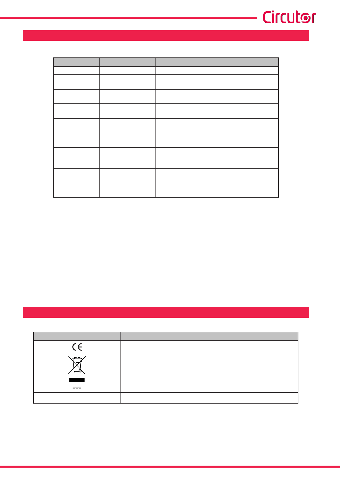
SYMBOLS
Table 2: Symbols�
Symbol Description
Compliant with the relevant European standards.
Device covered by European directive 2012/19/EC. At the end of its useful
life, do not leave the unit in a household waste container. Follow local regulations on electronic equipment recycling.
DC current
~
AC current
Note: The images of the devices are solely for the purpose of illustration and may differ from
the original device.
Instruction Manual
5
Page 6
1�- VERIFICATION UPON RECEPTION
Check the following points upon receiving the device:
a) The device meets the specications described in your order.
b) The device has not suffered any damage during transport.
c) Perform an external visual inspection of the device prior to switching it on.
d) Check that it has been delivered with the following:
- An installation guide.
- Safety label (terminal cover).
If any problem is noticed upon reception, immediately contact the transport
company and/or CIRCUTOR's after-sales service.
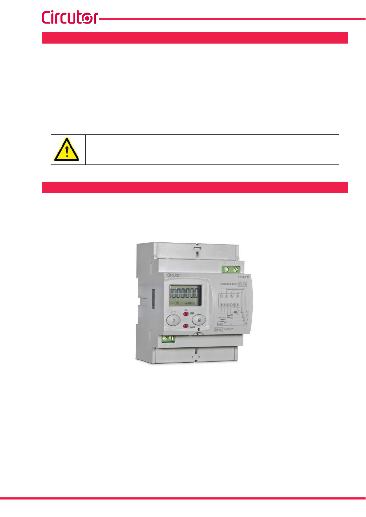
2�- PRODUCT DESCRIPTION
CEM-C31
The CEM-C31 static three-phase energy meter measures class B active energy (EN50470) /
class 1(IEC 62053-21) and (optional) class 2 reactive energy (IEC 62053-23).
The current is measured with the transformer.
The device features:
- 2 buttons that allow you to browse the different screens and program the device.
- 2 Verication LEDs.
- LCD display, displays all parameters,
- 2 connection seals,
- 2 terminal covers, to cover the top of the terminal box and the xing screws.
- RS-485 communications (CEM-C31-485-xx models).
- Optical communications port for communications with other modules installed on a
DIN rail with a service port (CEM-C31-T1 model).
- Impulse output (models CEM-C31-T1 and CEM-C31-485-T1).
- Digital input (model CEM-C31-485-DS).
6
Instruction Manual
Page 7
CEM-C31
3�- DEVICE INSTALLATION
3.1.- PRELIMINARY RECOMMENDATIONS
In order to use the device safely, it is critical that individuals who handle it follow
the safety measures set out in the standards of the country where it is being used,
use the necessary personal protective equipment, and pay attention to the various warnings indicated in this instruction manual.
The CEM-C31 device must be installed by authorised and qualied staff.
The power supply plug must be disconnected and measuring systems switched off before
handling, altering the connections or replacing the device. It is dangerous to handle the device
while it is powered.
Also, it is critical to keep the cables in perfect condition in order to avoid accidents, personal
injury and damage to installations.
The manufacturer of the device is not responsible for any damage resulting from failure by the
user or installer to observe the warnings and/or recommendations set out in this manual, nor for
damage resulting from the use of non-original products or accessories or those made by other
manufacturers.
If an anomaly or malfunction is detected in the device, do not use the device to take any measurements.
Inspect the work area before taking any measurements. Do not take measurements in dangerous areas or where there is a risk of explosion.
Disconnect the device from the power supply (device and measuring system
power supply) before maintaining, repairing or handling the device's connections.
Please contact the after-sales service if you suspect that there is an operational fault in the device.
Instruction Manual
7
Page 8
CEM-C31
3.2.- INSTALLATION
On the side of the device are all of the indications adjusted to the CEI 62052-11 standard.
The device is installed on a DIN rail. All electrical con nections must be covered by the plastic
covers, and only the display and keypad should remain exposed.
Terminals, opening covers or removing elements can expose parts that are
hazardous to the touch while the device is powered. Do not use the device
until it is fully installed.
3.3.- DEVICE TERMINALS
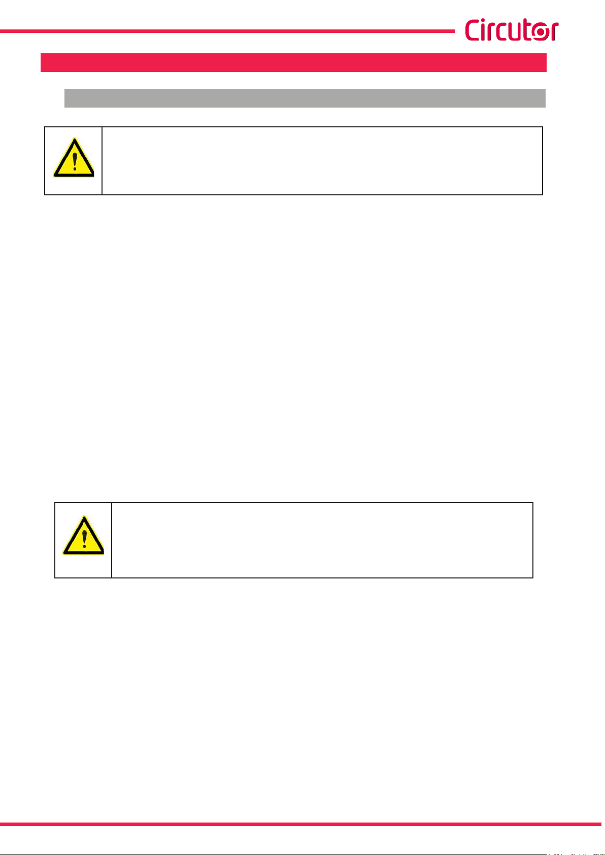
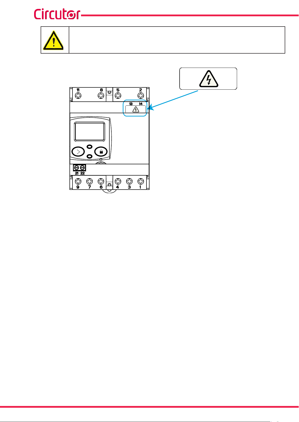
3�3�1� MODEL CEM-C31-T1
Table 3:List of CEM-C31-T1 terminals�
Device terminals
1 : S1, Current input L1 8 : L3, Voltage input L3
2 : L1, Voltage input L1 9 : S2, Current output L3
3 : S2, Current output L1 11 : N, Neutral connection
4 : S1, Current input L2 13 : Auxiliary Power Supply
5 : L2, Voltage input L2 14 : Auxiliary Power Supply
6 : S2, Current output L2 21 : Impulse output (Collector)
7 : S1, Current input L3 22 : Impulse output (Emitter)
Figure 1:Terminals of the CEM-C31-T1�
8
Instruction Manual
Page 9
CEM-C31
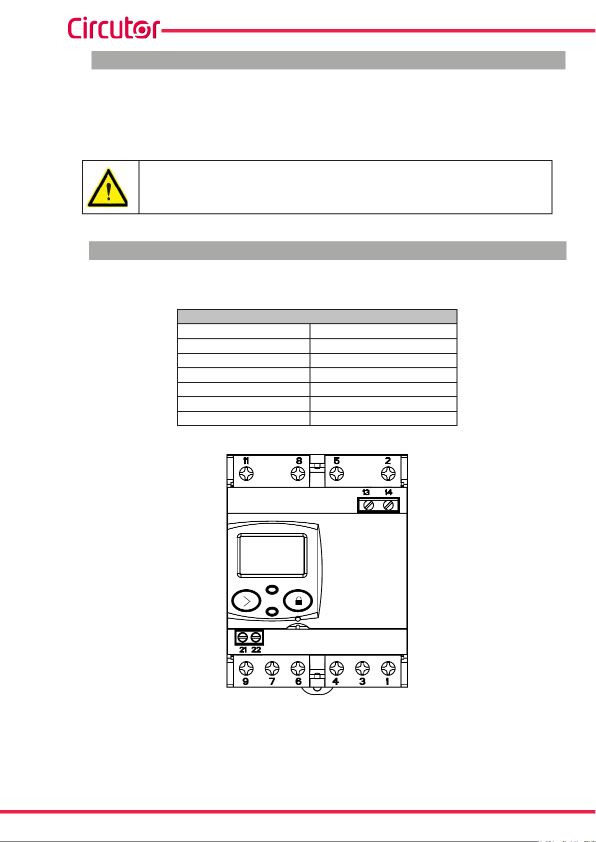
3�3�2� MODEL CEM-C31-485-T1
Table 4:List of CEM-C31-485-T1 terminals�
1 : S1, Current input L1 9 : S2, Current output L3
2 : L1, Voltage input L1 11 : N, Neutral connection
3 : S2, Current output L1 13 : Auxiliary Power Supply
4 : S1, Current input L2 14 : Auxiliary Power Supply
5 : L2, Voltage input L2 21 : Impulse output (Collector)
6 : S2, Current output L2 22 : Impulse output (Emitter)
7 : S1, Current input L3 23: B(-), RS-485
8 : L3, Voltage input L3 24: A(+), RS-485
Device terminals
Figure 2:Terminals of the CEM-C31-485-T1 and CEM-C31-485-DS�
3�3�3� MODEL CEM-C31-485-DS
Table 5:List of CEM-C31-485-DS terminals�
1 : S1, Current input L1 9 : S2, Current output L3
2 : L1, Voltage input L1 11 : N, Neutral connection
3 : S2, Current output L1 13 : Auxiliary Power Supply
4 : S1, Current input L2 14 : Auxiliary Power Supply
5 : L2, Voltage input L2 21: Digital input
6 : S2, Current output L2 22: Digital input (common)
7 : S1, Current input L3 23: B(-), RS-485
8 : L3, Voltage input L3 24: A(+), RS-485
Device terminals
Instruction Manual
9
Page 10
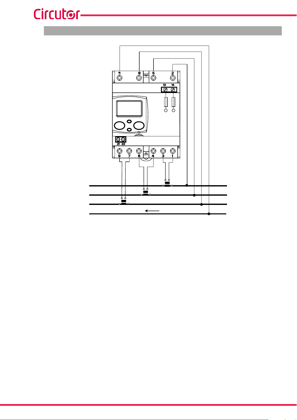
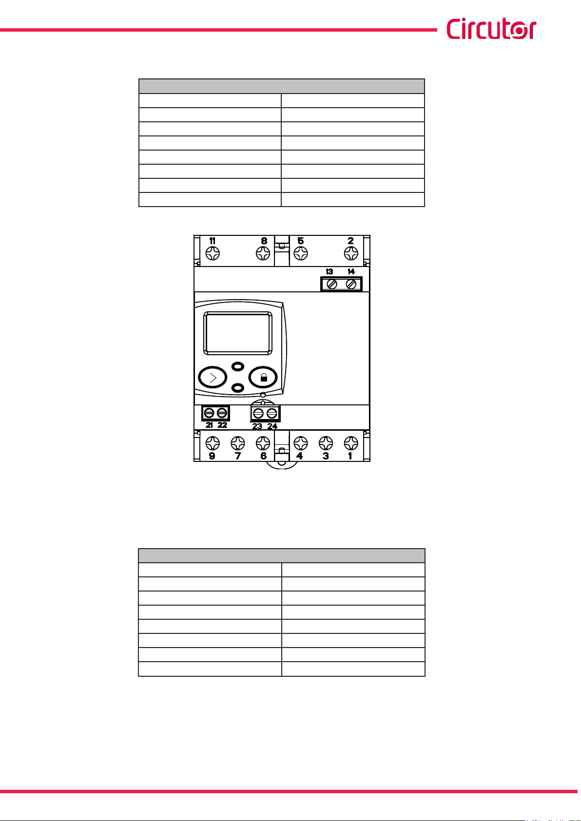
3.4.- CONNECTION DIAGRAM
CEM-C31
Power
Supply
LOAD
S2 S1
P1
P2
P1
S2 S1
P2
S2 S1
P2
P1
Figure 3: Connection diagram, CEM-C31�
L1
L2
L3
N
10
Instruction Manual
Page 11
CEM-C31
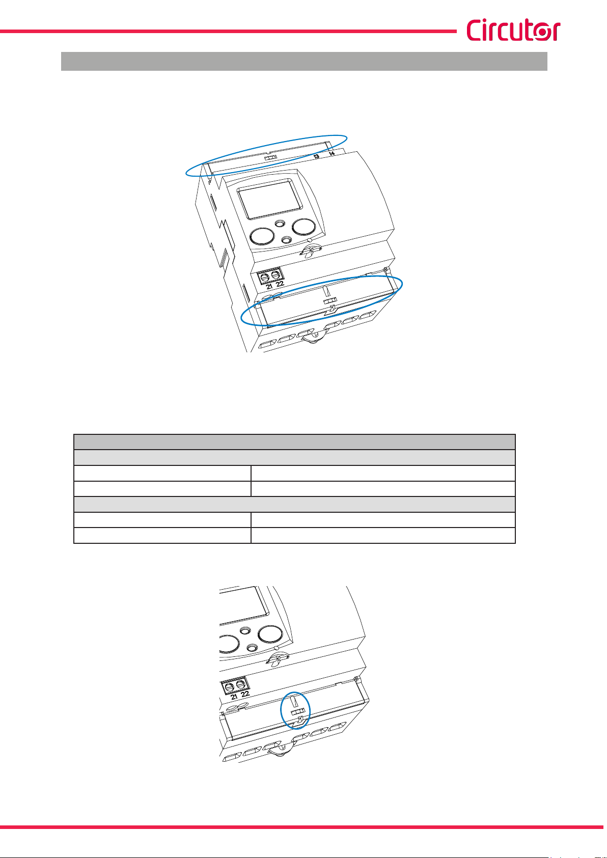
3.5.- CONNECTIONS
The CEM-C31 has terminal covers to cover the top of the terminal box and the xing screws
(Figure 4).
Figure 4: Terminal covers of the CEM-C31�
The xing screws are of the mixed type, allowing the use of PZ2 and at head screwdrivers.
Table 6:CEM-C31 connections�
Connections
Measurement terminals (1, 2� 3, 4, 5, 6, 7, 8, 9, 11)
Maximum cable cross-section 16 mm2 ( 10 mm2 with end sleeve ) ≤ 1.2 Nm
Screwdrivers head PZ2
Impulse output terminals / Digital input (21, 22), Power supply (13, 14) and RS-485 (23, 24)
Maximum cable cross-section 1.5 mm2 ( 1.5 mm2 with end sleeve ) ≤ 0.6 Nm
Screwdrivers head at head (3 x 0.5 mm)
Once connected, the device can be protected with two connection seals (Figure 5).
Instruction Manual
Figure 5: Seal of the CEM-C31�
11
Page 12
CEM-C31
Once the device is powered, attach the safety label (Figure 6) to terminals 13
and 14 to seal the device.
13 14
13 14
Figure 6: Attaching the safety label�
12
Instruction Manual
Page 13
CEM-C31
4�- OPERATION
The CEM-C31 is an energy meter capable of measuring:
Imported and exported active energy and reactive energy in the four quadrants.
(according to version).
Active, reactive and apparent power (according to version).
RMS voltage and current.
Power factor, PF
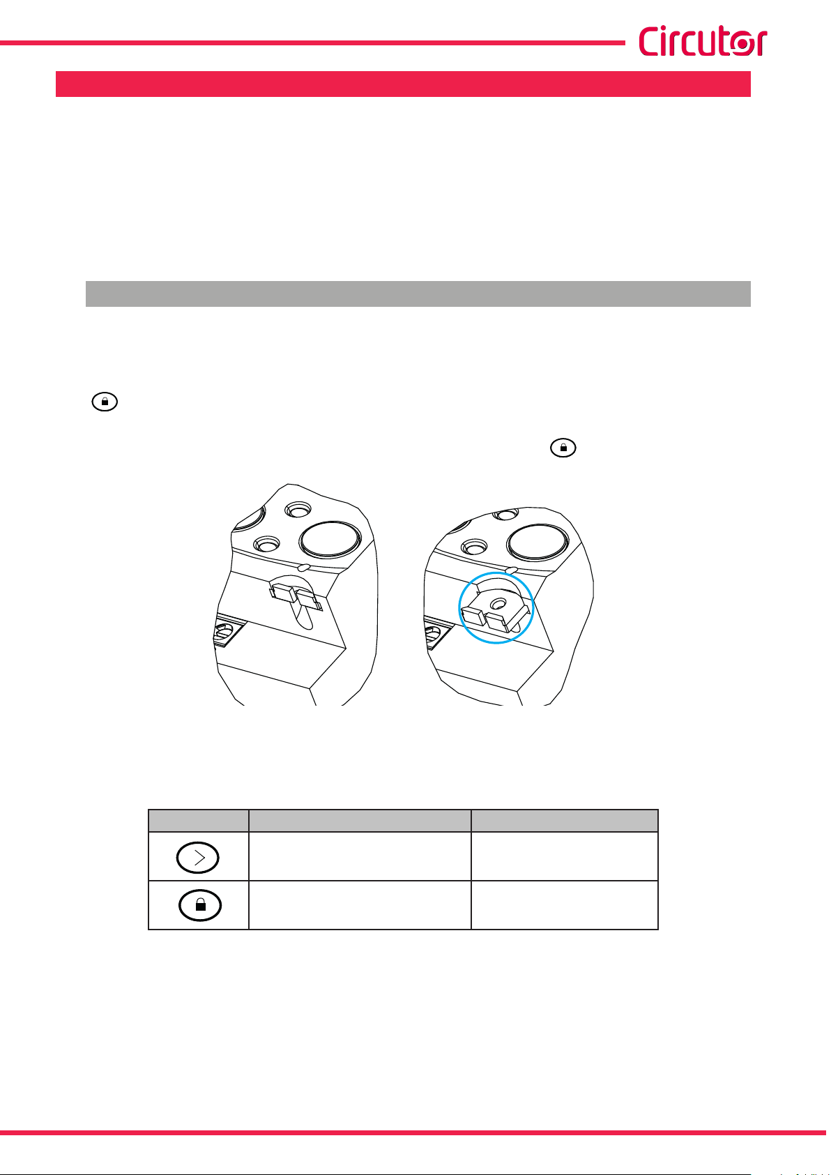
4.1.- BUTTON FUNCTIONS
The CEM-C31 has 2 buttons that allow you to browse the different screens and program the
device.
The button can be sealed to prevent access to the programming of the most relevant parameters.
To seal the button, insert the seal through the slot found under the button, Figure 7.
Figure 7: Sealing the button�
Button functions on the measuring screens (Table 7):
Table 7: Button functions on measuring screens�
Button Short press Long press (> 2 s)
For the cyclic movement.
Next screen.
Enters reading mode.
Instruction Manual
Enter the programming menu -
13
Page 14
CEM-C31
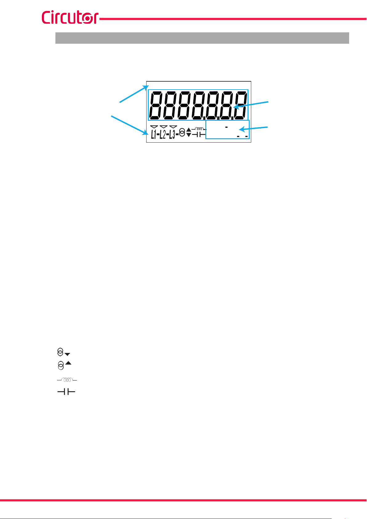
4.2.- DISPLAY
The device has an LCD where all parameters are displayed. The display is divided into three
areas (Figure 8):
COM MAX DEM
HOURS kgC0
2 COST PAR
T1 T2
Data line
Indicator
kWh
kVArh
Figure 8: CEM-C31 Display areas
Data line, displaying the values measured by the device.
Units, where the unit of the magnitude being viewed is shown.
Indicators, which shows other parameters:
COM, indicates that there is a communications module connected. It ashes when the
communications are established.
HOURS, displays the time in hours.
kgCO2, displays the quantity of kgCO2 released into the atmosphere according to the
energy consumed.
%
L
PF
C
Units
COST, indicates that the variable displayed in the data line is a cost.
PAR, indicates that the variable displayed in the data line is a partial meter.
T1 and T2, indicate the tariff corresponding to the on-screen information.
L1 - L2 - L3 - Indicates the presence of voltage in each phase, with its corresponding
current direction:
“ - “ is used to show the power yielded to the network.
“ “ is used to show the power absorbed by the network.
Indicates that the energy being viewed is generated.
Indicates that the energy being viewed is consumed.
Indicates that the energy is inductive.
Indicates that the energy is capacitive.
14
Instruction Manual
Page 15
Reactive LED
CEM-C31
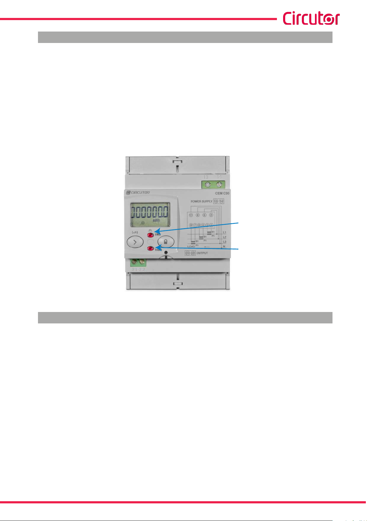
4.3.- LED INDICATORS
The device has two verication LEDs:
To verify the active energy�
To verify the reactive energy (according to version).
The weight of the LEDs is 20,000 imp/kWh (kvarh).
The LEDs will remain lit when the current is lower than the energy meter start-up current. Once
the start-up current is exceeded (due to active or reactive power consumption) the LEDs are
turned off and emit impulses that are proportional to the measured energy.
Active LED
Figure 9:LED Indicators of the CEM-C31�
4.4.- IMPULSE OUTPUT (CEM-C31-T1 and CEM-C31-485-T1 models)
The energy meter has optocoupler type outputs capable of generating impulses at a previously programmed rate. (See “6.2.1. IMPULSE OUTPUT WEIGHT” and ”6.2.2. IMPULSE OUTPUT
TYPE” )
Instruction Manual
15
Page 16
21
CEM-C31
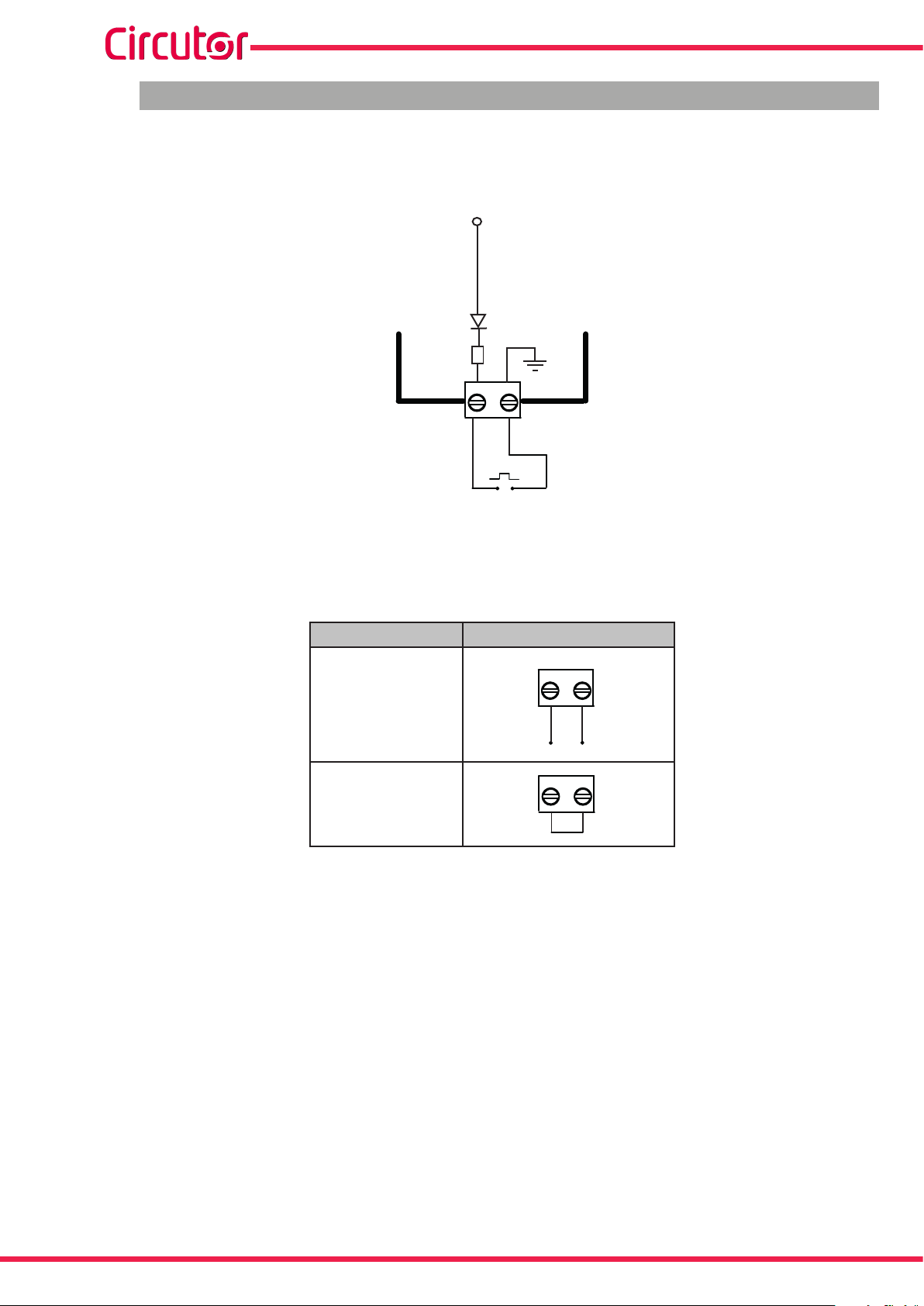
4.5.- DIGITAL INPUT (CEM-C31-485-DS)
The CEM-C31-485-DS model features a impulse input (terminals 21 and 22 in Table 5), to
calculate other supplies or select tariffs.
5 V DC
COMM
470 Ω
Active Tariff selection:
21
Figure 10: Digital input, CEM-C31-485-DS�
Table 8: Tariff selection�
Tariff Tariff selection
Tariff 1
21
22
22
22
Tariff 2
16
Instruction Manual
Page 17
CEM-C31
5�- DISPLAY
The CEM-C31 has 2 display modes:
Display in standby mode
Display in reading mode
5.1.- DISPLAY IN STANDBY MODE
With the display in standby mode, all of the information is presented in cyclic form without any
need to perform any action on the CEM-C31 buttons.
This mode displays different parameters, see Table 9 and Table 10, that alternate every 6
seconds.
The device is in this mode by default when none of the buttons are pressed.
Short press the button to stop the cyclic movement of the parameter being shown at the
time.
From then on, short press the button to browse all the parameters dened in Table 9 and
Table 10.
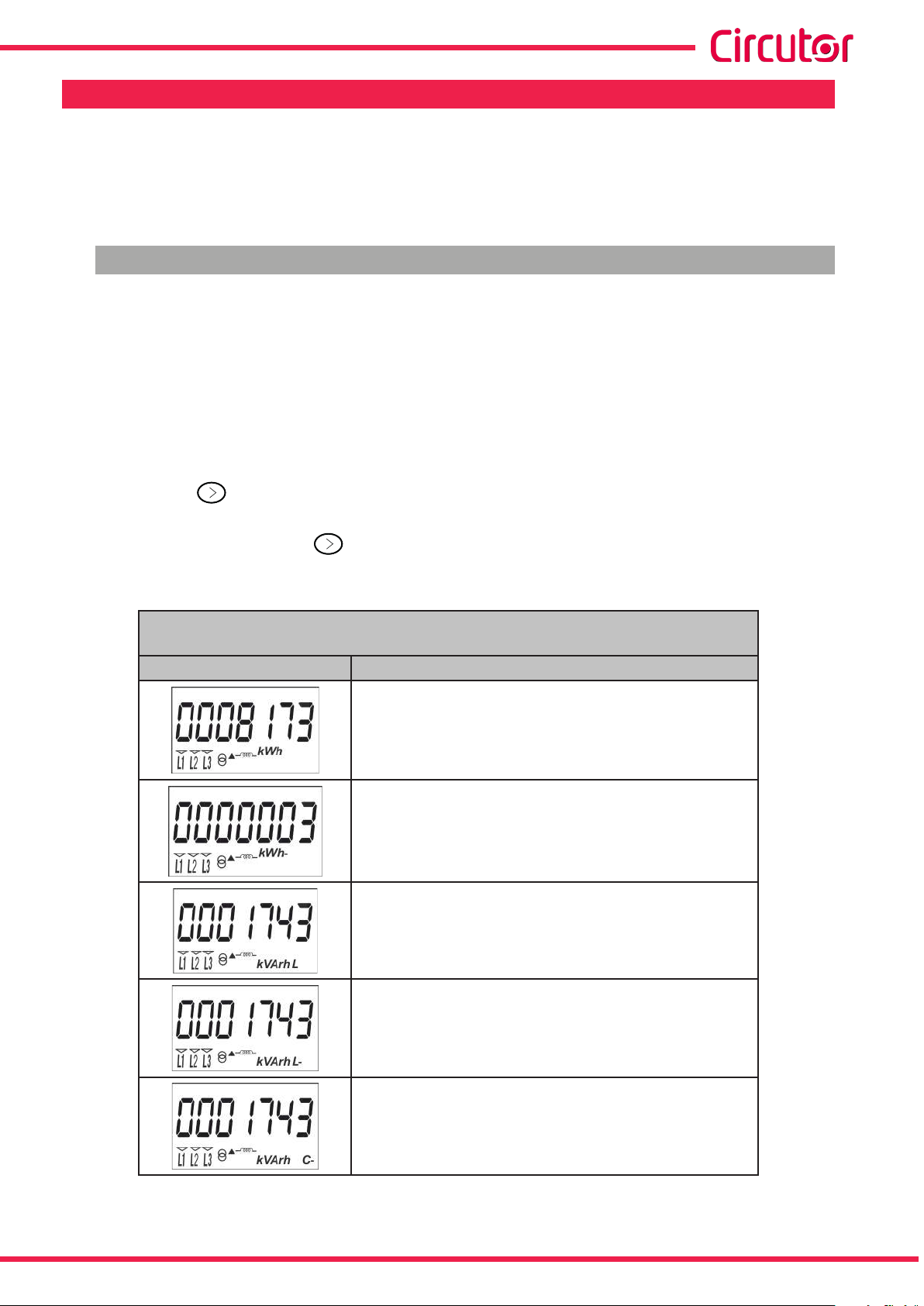
Table 9: Standby mode displays (Table 1)
Models CEM-C31-T1, CEM-C31-485-T1, CEM-C31-485-DS
(Impulse count option
Screen Parameters
Total imported active energy
Total exported active energy
Only displayed in the 4-quadrant version.
Reactive energy quadrant L+ total
(1)
)
(2)
Instruction Manual
Reactive energy quadrant L- total
(2)
Only displayed in the 4-quadrant version.
Reactive energy quadrant C- total
(2)
Only displayed in the 4-quadrant version.
17
Page 18
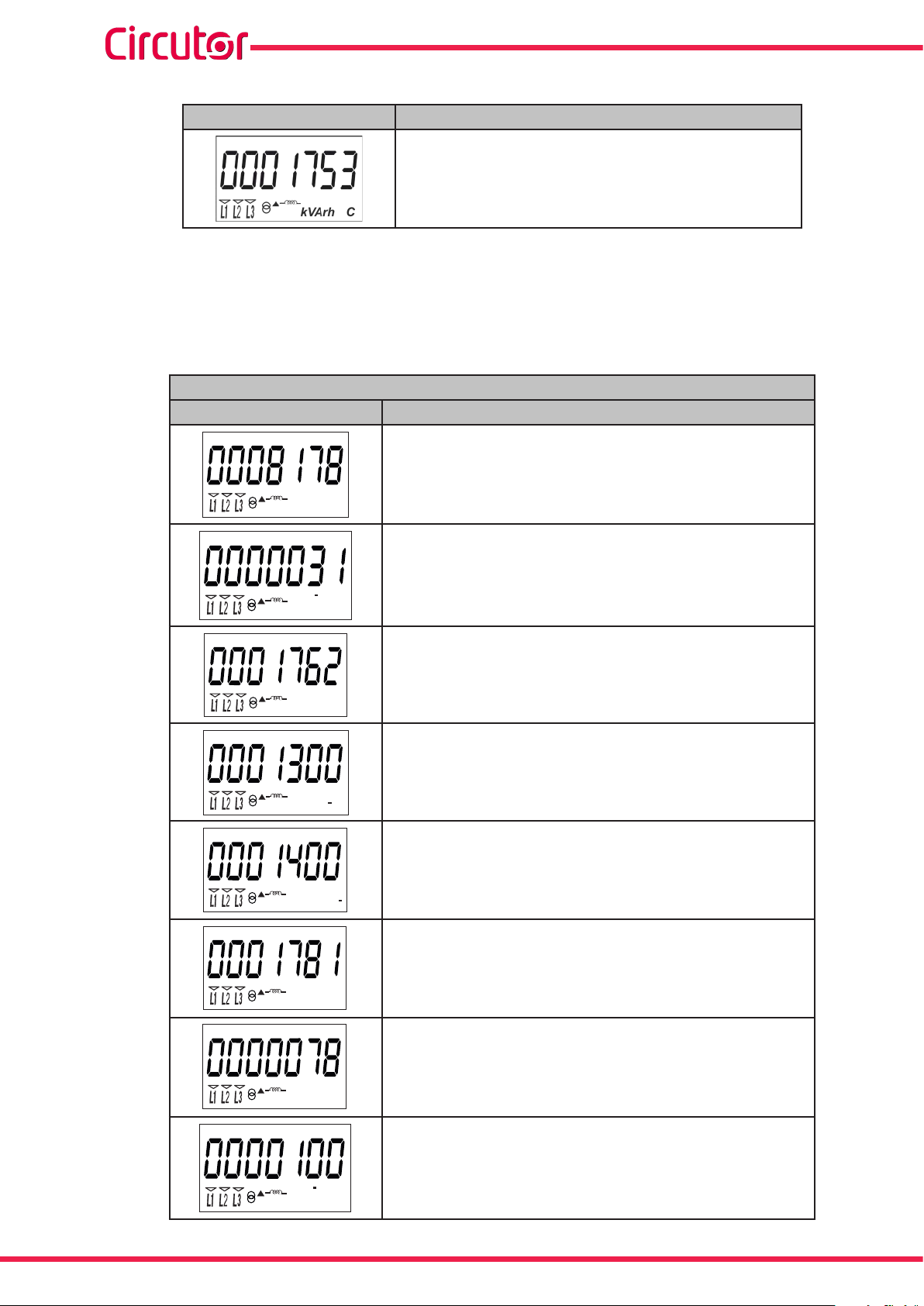
Table 9 (Continuation): Standby mode displays (Table 1)
Screen Parameters
CEM-C31
Reactive energy quadrant C+ total
(1)
The impulse count option for the CEM-C31-485-DS model can be congured in section “6.2.3.-
(2)
DIGITAL INPUT TYPE”
(2)
Only displayed if the reactive energy display option has been selected in the setup menu ( see
“6�2�7�2� REACTIVE ENERGY DISPLAY”).
Table 10: Standby mode displays (Table 2)�
Model CEM-C31-485-DS (Tariff option
(3)
)
Screen Parameters
T1
Imported active energy Tariff 1
kWh
T1
Exported active energy Tariff 1
kWh
Only displayed in the 4-quadrant version.
kVArh
kVArh
kVArh
kVArh
kWh
T1
Reactive energy quadrant L+ Tariff 1
L
T1
Reactive energy quadrant L- Tariff 1
(4)
(4)
Only displayed in the 4-quadrant version.
L
T1
Reactive energy quadrant C- Tariff 1
(4)
Only displayed in the 4-quadrant version.
C
T1
Reactive energy quadrant C+ Tariff 1
C
T2
(4)
Imported active energy Tariff 2
18
kWh
T2
Exported active energy Tariff 2
Only displayed in the 4-quadrant version.
Instruction Manual
Page 19

CEM-C31
Table 10 (Continuation) : Standby mode displays (Table 2)�
Screen Parameters
T2
(4)
(4)
kVArh
Reactive energy quadrant L+ Tariff 2
L
T2
Reactive energy quadrant L- Tariff 2
Only displayed in the 4-quadrant version.
L
kVArh
T2
Reactive energy quadrant C- Tariff 2
(4)
Only displayed in the 4-quadrant version.
C
kVArh
T2
Reactive energy quadrant C+ Tariff 2
C
kVArh
(3)
The impulse count option for the CEM-C31-485-DS model can be congured in section “6.2.3.-
(4)
DIGITAL INPUT TYPE”
(4)
Only displayed if the reactive energy display option has been selected in the setup menu ( see
“6.2.7.2. REACTIVE ENERGY DISPLAY”).
When the active Tariff does not match the Tariff being displayed, a ashing active Tariff indicator
is displayed.
The standby mode is activated again when no button is pressed for 60 seconds.
Instruction Manual
19
Page 20

CEM-C31
5.2.- DISPLAY IN READING MODE
The reading mode is activated by a long press on the button.
In reading mode you can:
View the voltage, current, active power, apparent power and power factor of the
installation.
View the energies of the partial energy meters.
Impulse count display (CEM-C31-485-DS model)
Enter the setup menu.
View the manufacturer information.
The navigation diagram is shown in Figure 11:
T1
kWh
> 2s
> 2s
Instantaneous Value
Partial energy
Impulse count (CEM-Cx1-485-DS)
General configuration
Manufacturer information
20
Figure 11: Navigation diagram in reading mode of the CEM-C31�
Instruction Manual
Page 21

CEM-C31
5.3.- INSTANTANEOUS VALUE DISPLAY
To open the screens where the instantaneous value are viewed, long press the key on the
display in standby mode. The home screen is displayed Figure 12 :
Figure 12: Instantaneous Value main screen�
Long press the button to open the different screens.
Short press the button to browse the different screens (see Table 11).
Long press the button to exit the instantaneous values screens.
The standby mode is activated again when no button is pressed for 60 seconds.
Table 11: Instantaneous value screens�
Screen Parameters
L1 Voltage
L2 Voltage
L3 Voltage
Instruction Manual
L1 Current
L2 Current
L3 Current
21
Page 22

Table 11 (Continuation): Instantaneous value screens�
Screen Parameters
Active three-phase power
CEM-C31
Reactive three-phase power
Apparent three-phase power
L1 Power Factor
L2 Power Factor
L3 Power Factor
(5)
CEM-C31-T1, CEM-C31-485-T1, CEM-C31-485-DS models
(6):
Hours of operation from manufacture
HOURS T1
CEM-C31-485-DS model
(7)
:
Tariff 1 operating hours, from manufacture
HOURS T2
CEM-C31-485-DS model
(7)
:
Tariff 2 operating hours, from manufacture
(5)
The device must be connected to the L1 phase to calculate the reactive power.
(6)
Visible display for the CEM-C31-485-DS model with impulse count option, see “6.2.3.- DIGITAL INPUT
TYPE”
(7)
Visible display for the CEM-C31-485-DS model with tariff option, see “6.2.3.- DIGITAL INPUT TYPE”
22
Instruction Manual
Page 23

CEM-C31
5.4.- PARTIAL ENERGY DISPLAY
Note: The partial energy display menu is only displayed if the partial energy display option has
been selected in the setup menu (see “6�2�7�1� PARTIAL ENERGY DISPLAY” )
Long press the key in the standby mode screen to open these display screens. Short press
the key to display the partial energy main screen, Figure 13.
Figure 13: Partial energy main screen�
Long press the button to open the different screens. Short press the button to browse the
different screens (see Table 12 and Table 13).
The PAR icon on the display indicates that you are viewing the partial energies.
Long press the button to exit the Partial energy screens.
The standby mode is activated again when no button is pressed for 60 seconds.
Table 12:Partial energy screens (Table 1)�
Models CEM-C31-T1, CEM-C31-485-T1, CEM-C31-485-DS
(Impulse count option
Screen Parameters
Partial imported active energy
Partial exported active energy
Only displayed in the 4-quadrant version.
(8)
)
Instruction Manual
Partial reactive energy, quadrant 1 (L+)
Partial reactive energy, quadrant 2 (L-)
Only displayed in the 4-quadrant version.
(9)
(9)
23
Page 24

Table 12 (Continuation): Partial energy screens (Table 1)�
Screen Parameters
CEM-C31
Partial reactive energy, quadrant 3 ( C-)
(9)
Only displayed in the 4-quadrant version.
Partial reactive energy, quadrant 4 ( C+)
(9)
Hours in partial operation
(since the last partial reset )
Cost of the partial active energy consumed
(since the last partial reset )
(10)
CO2 emissions into the atmosphere.
(since the last partial reset )
(10)
(8)
The impulse count option for the CEM-C31-485-DS model can be congured in section “6.2.3.-
DIGITAL INPUT TYPE”
(
9)
Only displayed if the reactive energy display option has been selected in the setup menu (see “6.2.7.2.
REACTIVE ENERGY DISPLAY”).
(10)
Only displayed if the efficiency factors display option has been selected in the setup menu
(see“6.2.7.3. EFFICIENCY FACTORS DISPLAY”).
Table 13: Partial energy screens (Table 2)�
Model CEM-C31-485-DS (Tariff option
(11)
)
Screen Parameters
PAR
T1
Partial imported active energy Tariff 1
kWh
PAR
T1
Partial exported active energy Tariff 1
kWh
PAR
T1
Only displayed in the 4-quadrant version.
24
kVArh
Partial reactive energy, quadrant 1(L+) Tariff 1.
L
(12)
Instruction Manual
Page 25

CEM-C31
Tabla 13 (Continuation) : Partial energy screens (Table 2)�
Screen Parameters
PAR
T1
Partial reactive energy, quadrant 2 (L-) Tariff 1.
Only displayed in the 4-quadrant version.
L
kVArh
PAR
T1
(12)
kVArh
kVArh
kWh
kWh
Partial reactive energy, quadrant 3 (C-) Tariff 1.
(12)
Only displayed in the 4-quadrant version.
C
PAR
T1
Partial reactive energy, quadrant 4 (C+) Tariff 1.
(12)
C
PAR
T2
Partial imported active energy Tariff 2
PAR
T2
Partial exported active energy Tariff 2
Only displayed in the 4-quadrant version.
PAR
T2
Partial reactive energy, quadrant 1 (L+) Tariff 2.
(12)
L
kVArh
PAR
kVArh
PAR
kVArh
PAR
kVArh
HOURS PAR T1
T2
Partial reactive energy, quadrant 2 (L-) Tariff 2.
(12)
Only displayed in the 4-quadrant version.
L
T2
Partial reactive energy, quadrant 3 (C-) Tariff 2.
(12)
Only displayed in the 4-quadrant version.
C
T2
Partial reactive energy, quadrant4 (C+) Tariff 2.
(12)
C
Hours in partial operation Tariff 1.
(since the last partial reset )
Instruction Manual
25
Page 26

Tabla 13 (Continuation) : Partial energy screens (Table 2)�
Screen Parameters
COST PAR T1
Cost of the partial active energy consumed Tariff 1
(since the last partial reset )
kgC02 PAR T1
CO2 emissions into the atmosphere Tariff 1
(since the last partial reset )
HOURS PAR T2
Hours in partial operation Tariff 2.
(since the last partial reset )
COST PAR T2
Cost of the partial active energy consumed Tariff 2
(since the last partial reset )
CEM-C31
(13)
(13)
(13)
kgC02 PAR T2
CO2 emissions into the atmosphere Tariff 2
(since the last partial reset )
(11)
The tariff option for the CEM-C31-485-DS model can be congured in section “6.2.3.- DIGITAL INPUT
TYPE”
(
12)
Only displayed if the reactive energy display option has been selected in the setup menu (see
“6.2.7.2. REACTIVE ENERGY DISPLAY”).
(13)
Only displayed if the efciency factors display option has been selected in the setup menu (see
“6�2�7�3� EFFICIENCY FACTORS DISPLAY”).
5.5.- IMPULSE COUNT DISPLAY (CEM-C31-485-DS)
(13)
Note: The impulse count display screens are only visible if the impulse count option has been
congured in the CEM-C31-485-DS model.
To access the pulse count screens, press the key for a prolonged time on the screen in
standby mode. Short presses will display the initial impulse count screen, Figure 14:
26
Figure 14: Main impulse count screen�
Instruction Manual
Page 27

CEM-C31
To access the different screens, press key for a prolonged time.
Short press the button to browse the different screens (Table 14).
To exit the impulse count screens, press key for a prolonged time.
The standby mode is activated again when no button is pressed for 60 seconds.
Table 14: Impulse count screens�
Screen Parameters
Total impulse count
PAR
Partial impulse count
(
14)
Only visible if the partial energy display has been selected in the setup menu (see “6.2.7.1. PARTIAL
ENERGY DISPLAY”).
5.6.- MANUFACTURER INFORMATION SCREEN
(14)
Long press the button in the standby mode screen to open these display screens. Short
press the button to display the manufacturer information home screen, Figure 15:
Figure 15: Manufacturer information home screen�
Long press the button to open the different screens.
Short press the button to browse the different screens (see Table 15).
Long press the button to exit the instantaneous values screens.
The standby mode is activated again when no button is pressed for 60 seconds.
Table 15: Manufacturer information screens�
Screen Parameters
Device model
Instruction Manual
27
Page 28

Table 15 (Continuation): Manufacturer information screens�
Screen Parameters
Version
CEM-C31
Communications protocol
(15)
Communications protocol
version
(15)
Active energy with resolution in Wh
Reactive energy with resolution varh
(15)
The screen is displayed if it is a CEM-C31-T1 and there is a CEM M-RS485 (communications inter-
32-bit CRC
face for the CEM family of devices) connected to the device.
28
Instruction Manual
Page 29

CEM-C31
6�- CONFIGURATION
The CEM-C31 have 2 conguration menus:
Metrologically relevant parameters configuration menu.
General configuration menu.
6.1.- RELEVANT PARAMETERS CONFIGURATION
The most relevant parameters in metrological terms are congured in the programming menu.
Short press the button to access this menu.
This button is sealable, see “4.1.- BUTTON FUNCTIONS”, to restrict access to the programming
procedures.
The standby mode is activated again when no button is pressed for 60 seconds or by short
pressing the button.
6�1�1� VOLTAGE PRIMARY TRANSFORMATION RATIO
This is the home screen for entering the voltage primary ratio.
Long press the button to view the value to be programmed.
To write or modify the value, short press the button
repeatedly, increasing the value of the ashing digit.
When the desired value is shown on the screen, move onto the next digit with a long press on
the button, allowing the remaining values to be modied.
To validate the data, move to the last digit and long press the button; the validation screen
will appear (Figure 16) indicating that the setup value has been saved.
Figure 16: Validation screen�
Instruction Manual
29
Page 30

CEM-C31
After a few seconds viewing the screen shown on Figure 16 , the system returns to the main
screen of the Primary voltage transformation ratio.
Short press the button to access the next programming step
6�1�2� VOLTAGE SECONDARY TRANSFORMATION RATIO
This is the home screen for entering the voltage secondary ratio.
Long press the button to view the value to be programmed.
To write or modify the value, short press the button
repeatedly, increasing the value of the ashing digit.
When the desired value is shown on the screen, move onto the next digit with a long press on
the button, allowing the remaining values to be modied.
To validate the data, move to the last digit and long press the button; the validation screen
will appear (Figure 16) indicating that the setup value has been saved.
After a few seconds viewing the screen shown on Figure 16 , the system returns to the main
screen of the Secondary voltage transformation ratio.
Short press the button to access the next programming step
6�1�3� CURRENT PRIMARY TRANSFORMATION RATIO
This is the home screen for entering the current primary ratio.
Long press the button to view the value to be programmed.
30
To write or modify the value, short press the button
repeatedly, increasing the value of the ashing digit.
Instruction Manual
Page 31

CEM-C31
When the desired value is shown on the screen, move onto the next digit with a long press on
the button, allowing the remaining values to be modied.
To validate the data, move to the last digit and long press the button; the validation screen
will appear (Figure 16) indicating that the setup value has been saved.
After a few seconds viewing the screen shown on Figure 16, the system returns to the main
screen of the Primary current transformation ratio.
Short press the button to access the next programming step
6�1�4� CURRENT SECONDARY TRANSFORMATION RATIO
This is the home screen for entering the current secondary ratio.
Long press the button to view the value to be programmed.
To write or modify the value, short press the button
repeatedly, increasing the value of the ashing digit.
When the desired value is shown on the screen, move onto the next digit with a long press on
the button, allowing the remaining values to be modied.
To validate the data, move to the last digit and long press the button; the validation screen
will appear (Figure 16) indicating that the setup value has been saved.
After a few seconds viewing the screen shown on Figure 16 , the system returns to the main
screen of the Secondary current transformation ratio.
6�1�5� EXITING THE SETUP MENU
When this screen is displayed:
Instruction Manual
Long press the button to exit the programming menu.
Short press the button to return to the rst programming
point ( “6.1.1. VOLTAGE PRIMARY TRANSFORMATION RATIO”)
31
Page 32

CEM-C31
6.2.- GENERAL CONFIGURATION MENU
Long press the button in the standby mode screen to open these setup screens. Short
press the button to display the home screen, Figure 17:
Figure 17: Programming home screen
In the setup menu you can:
Program the weight and type of impulse output
Program the digital input operating mode.
Program the communications.
Program the display screen.
Program the cost of the energy and the CO2. emissions
Delete the partial energy meters.
The standby mode is activated again when no button is pressed for 60 seconds.
Long press the button to access the rst programming step.
6�2�1� IMPULSE OUTPUT WEIGHT
Note: Screen only visible for CEM-C31-T1 and CEM-C31-485-T1 models.
This is the home screen for entering the weight of the impulse
output.
Long press the button to view the value to be programmed.
To write or modify the value, short press the button
repeatedly, increasing the value of the ashing digit.
32
When the desired value is shown on the screen, move onto the next digit with a long press on
the button, allowing the remaining values to be modied.
To validate the data, move to the last digit and long press the button; the validation screen
will appear (Figure 18) indicating that the programming value has been saved.
Instruction Manual
Page 33

CEM-C31
Figure 18: Validation screen�
After a few seconds viewing the screen shown on Figure 18 , the system returns to the Impulse
output weight programming main screen.
Minimum value: 99999.
Maximum value: 0.
Short press the button to access the next programming step.
6�2�2� IMPULSE OUTPUT TYPE
Note: Screen only visible for CEM-C31-T1 and CEM-C31-485-T1 models.
The impulse output type is selected on this screen, between:
kWh or KVArh�
Short press the button to browse the different options.
To validate the data, long press the button and the validation screen will appear
(Figure 18) indicating that the programming value has been saved.
After a few seconds viewing the screen shown on Figure 18 , the system returns to the Impulse
output type programming main screen.
Short press the button to access the next programming step.
6�2�3�- DIGITAL INPUT TYPE
Note: Screen only visible for the CEM-C31-485-DS model.
The digital input operation is selected from this screen: Count (as
impulse counter) or tariff (Tariff Operation).
Short press the button to browse the different options.
To validate the data, long press the button and the validation screen will appear
(Figure 18) indicating that the programming value has been saved.
After a few seconds displaying the screen in Figure 18, it returns to the main digital input Type
Instruction Manual
33
Page 34

CEM-C31
programming screen.
Short press the button to access the next programming step.
6�2�4� PERIPHERAL ADDRESS
Note: This is only displayed if it is a CEM-C31-485-T1 or CEM-C31-485-DS or if there is a CEM
M-RS485 (communications interface for the CEM family of devices) connected to the CEM-
C31-T1 model.
This is the home screen for entering the peripheral address.
Long press the button to view the value to be programmed.
To write or modify the value, short press the button
repeatedly, increasing the value of the ashing digit.
When the desired value is shown on the screen, move onto the next digit with a long press on
the button, allowing the remaining values to be modied.
To validate the data, move to the last digit and long press the button; the validation screen
will appear (Figure 18) indicating that the programming value has been saved.
After a few seconds viewing the screen shown on Figure 18, the system returns to the
Peripheral address programming main screen.
Minimum value: 1.
Maximum value: 254
Short press the button to access the next programming step.
34
Instruction Manual
Page 35

CEM-C31
6�2�5� TRANSMISSION SPEED ( BAUD RATE)
Note: This is only displayed if it is a CEM-C31-485-T1 or CEM-C31-485-DS or if there is a CEM
M-RS485 (communications interface for the CEM family of devices) connected to the CEM-
C31-T1 model.
This is the home screen for entering the transmission speed.
Long press the button to view the value to be programmed.
The transmission speed (Baud rate) is selected on this screen,
and may be: 9600, 19200 or 38400�
Short press the button to browse the different options.
To validate the data, long press the button and the validation screen will appear
(Figure 18) indicating that the programming value has been saved.
After a few seconds viewing the screen shown on Figure 18, the system returns to the
Transmission speed programming main screen.
Short press the button to access the next programming step.
6�2�6� TYPE OF COMMUNICATIONS
Note: This is only displayed if it is a CEM-C31-485-T1 or CEM-C31-485-DS or if there is a CEM
M-RS485 (communications interface for the CEM family of devices) connected to the CEM-
C31-T1 model.
This is the home screen for selecting the number of bits, the
parity and the number of stop bits of the communications frame.
Long press the button to view the value to be programmed.
Instruction Manual
35
Page 36

CEM-C31
This screen shows the different options:
8n1 : 8 bits, no parity, 1 stop bit.
8E1 : 8 bits, even parity, 1 stop bit.
8o1 : 8 bits, odd parity, 1 stop bit.
8n2 : 8 bits, no parity, 2 stop bits.
8E2 : 8 bits, even parity, 2 stop bits.
8o2 : 8 bits, odd parity, 2 stop bits.
Short press the button to browse the different options.
To validate the data, long press the button and the validation screen will appear
(Figure 18) indicating that the programming value has been saved.
After a few seconds viewing the screen shown on Figure 18, the system returns to the
Communications type programming main screen.
Short press the button to access the next programming step.
6�2�7� DISPLAY
This is the home screen for selecting the unit display options.
Long press to access the partial energy display selection screen:
6�2�7�1� Partial energy display
This is the home screen for selecting the partial energy display
view option.
Long press to view the options.
36
The possible options are:
Yes, if you want to view the partial energy.
No, if you select this option, the unit stops recording the partial
energy. A display view is not provided and the value displayed by
communications is 0.
Para saltar entre las diferentes opciones pulsar la tecla de con
pulsaciones cortas.
To validate the data, long press the button. The device will return to the main programming
screen of the Partial energy display.
Short press to access the reactive energy display selection screen.
Instruction Manual
Page 37

CEM-C31
6�2�7�2� Reactive energy display
This is the home screen for selecting the reactive energy log
display view option.
Long press to view the options.
The possible options are:
Yes, if you want a display view of the reactive energy screens.
No, a display view of the reactive energy screens is not provided,
but a communications view is possible.
Short press the button to browse the different options.
To validate the data, long press the button. The device will return to the main programming
screen of the Reactive energy display.
Short press to access the efciency factors display selection screen:
6�2�7�3� Efciency factors display
This is the home screen for selecting the display view of the
efciency factors: Cost of energy and CO2 emissions.
Long press to view the options.
The possible options are:
Yes, if you want a display view of the efciency screens (cost of
energy and CO2 emissions).
No, if you select this option, the unit stops recording the efciency
factors. A display view is not provided and the value displayed by
communications is 0.
Short press the button to browse the different options.
To validate the data, long press the button. The device will return to the main programming
screen of the Efciency factors display.
Short press to access the display menu output screen:
Instruction Manual
37
Page 38

When this screen is displayed:
Short press the button to return to the rst conguration
point of the display ( “ 6.2.7.1. PARTIAL ENERGY DISPLAY”)
Long press the button to jump to the next programming
point.
6�2�8� BACKLIGHT
This is the home screen for selecting the backlight operating mode
of the screen in those units that feature it.
Long press to view the different options:
CEM-C31
This screen shows the different options:
On : Backlight always ON.
Off : Backlight always OFF.
005 SEC ... 120 SEC: ON time after the last press of the buttons.
Short press the button to browse the different options.
To validate the data, long press the button and the validation screen will appear (Figure
18) indicating that the programming value has been saved.
After a few seconds viewing the screen shown in Figure 18, it returns to the main programming
screen of the Backlight.
Short press the button to access the next programming step.
6�2�9� ENERGY COST
Note: It is only displayed if the efciency factors display has been selected.
38
This is the home screen for entering the energy cost per kWh.
Long press the button to view the value to be programmed.
Instruction Manual
Page 39

CEM-C31
To write or modify the value, short press the button
repeatedly, increasing the value of the ashing digit.
When the desired value is shown on the screen, move onto the next digit with a long press on
the button, allowing the remaining values to be modied.
To validate the data, move to the last digit and long press the button; the validation screen
will appear (Figure 18) indicating that the programming value has been saved.
After a few seconds viewing the screen shown on Figure 18 , the system returns to the Energy
cost programming main screen.
Minimum value: 0.000
Maximum value: 9999.999
Short press the button to access the next programming step.
6�2�10� CO2 EMISSIONS
Note: It is only displayed if the efciency factors display has been selected.
This is the home screen for entering the ratio of the carbon
emissions.
The carbon emissions ratio is the amount of emissions released
into the atmosphere to produce a unit of electricity (1 kWh).
The European mix ratio is approximately 0.65 kgCo2 per kWh.
Long press the button to view the value to be programmed.
To write or modify the value, short press the button
repeatedly, increasing the value of the ashing digit.
When the desired value is shown on the screen, move onto the next digit with a long press on
the button, allowing the remaining values to be modied.
To validate the data, move to the last digit and long press the button; the validation screen
will appear (Figure 18) indicating that the programming value has been saved.
After a few seconds viewing the screen shown on Figure 18, the system returns to the CO2
emissions programming main screen.
Minimum value: 0.000
Instruction Manual
39
Page 40

CEM-C31
Maximum value: 9.000
Short press the button to access the next programming step.
6�2�11� PARTIAL ENERGY METER DELETION
Note: It is only displayed if the partial energy display has been selected.
On this screen you select whether or not to delete the partial
energy meters.
Long press the button to delete the energy meters. The
validation screen (Figure 18) will be displayed next, indicating that
the energy meters were deleted correctly.
After a few seconds viewing the screen shown on Figure 18, the system returns to the Partial
energy meter deletion programming main screen.
Short press the button to access the next programming step.
6�2�12� EXITING THE SETUP MENU
When this screen is displayed:
Long press the button to exit the setup menu.
Short press the button to return to the rst setup point.
40
Instruction Manual
Page 41

CEM-C31
7�- COMMUNICATIONS
7.1.- INFRARED COMMUNICATIONS PORT (Model CEM-C31-T1)
The CEM-C31-T1 model, in all versions, the has a serial optical communications port, in compliance with the UNE EN 62056-21:2003 Standard.
7.2.- RS-485 COMMUNICATIONS PORT (Models CEM-C31-485-xx)
The CEM-C31-485-T1 and CEM-C31-485-DS models has an RS-485 communication port, with
MODBUS RTU ® protocol.
7�2�1�- CONNECTION
The RS-485 cable must be made up of a twisted pair cable with a braided shield with a
maximum distance of 1,200 metres between the CEM-C31-485-xx and the master device.
A maximum of 32 devices can be connected to this bus.
Use an intelligent RS-232 to RS-485 network protocol converter to establish communications
with the master device.
PC
RS-232 / USB / Ethernet / Profibus ...
RS-232
USB
Ethernet
Profibus
...
RS-485
Instruction Manual
RS-485
RS-485
B(-)A(+)
Figure 19: CEM-C31-485-T1 and CEM-C31-485-DS connection diagram�
A(+)B(-)
41
Page 42

CEM-C31
7�2�2�- MODBUS PROTOCOL
The MODBUS protocol is a communication standard in the industry that enables the network
connection of multiple devices, where there is a master and multiple slaves. Within the
MODBUS protocol the CEM-C31-485-xx uses the RTU (Remote Terminal Unit) mode.
In RTU mode, message starts and ends are detected with silences of at least 3.5 characters,
and the 16-bit CRC error-detection method is used.
The MODBUS functions implemented in the device are:
Functions 03 and 04. Reading registers.
Function 10. Writing multiple registers.
7�2�2�1�- Read commands
The CEM-C31-485-xx supports integer type read functions: 0x03 and 0x04.
Example: Reading of the device’s serial number with peripheral number 01.
We will send the following Modbus frame:
Address Function
01 04 2710 0002 CRC
Initial
register
Register
no�
CRC
The device will respond to us with the next frame:
Address Function No� of bytes Serial no� CRC
01 04 04 XXXX XXXX CRC
Note: The values are shown in hexadecimal.
The number of requested registers must be the same as the size of the variable requested.
It is possible to read several consecutive addresses, if the request meets the correct format.
7�2�2�2�- Write commands
42
The CEM-C31-485-xx supports integer type write Functions: 0x10.
Example: Changing the Modbus address of peripheral 01 to the address 0x000A.
We will send the following Modbus frame:
Address Function
01 10 03E8 0001 02 000A CRC
Initial
register
Register
no�
No� bytes Data CRC
Instruction Manual
Page 43

CEM-C31
The device will respond to us with the next frame:
Address Function
01 10 03E8 0001 CRC
Initial
Register
Register
no�
CRC
Note: The values are shown in hexadecimal.
The number of registers to write must be the same as the size of the variable that is being
accessed.
It is possible to write several consecutive addresses, if the request meets the correct format.
7�2�3�- VARIABLES MODBUS
All MODBUS map addresses are hexadecimal.
7�2�3�1�- Energy
The Read function is implemented for these variables.
Table 16: Modbus variables: Energy (Table 1)�
Description Address Size Units
Total values
Imported active energy 0x0000 32 bits Wh
Exported active energy 0x0002 32 bits Wh
Q1 reactive energy 0x0004 32 bits varh
Q2 reactive energy 0x0006 32 bits varh
Q3 reactive energy 0x0008 32 bits varh
Q4 reactive energy 0x000A 32 bits varh
Partial values
Partial imported active energy 0x0030 32 bits Wh
Partial exported active energy 0x0032 32 bits Wh
Q1 partial reactive energy 0x0034 32 bits varh
Q2 partial reactive energy 0x0036 32 bits varh
Q3 partial reactive energy 0x0038 32 bits varh
Q4 partial reactive energy 0x003A 32 bits varh
Table 17 shows energies per tariff, only visible for the CEM-C31-485-DS model with the Tariff
option selected.(See “6.2.3.- DIGITAL INPUT TYPE”).
Table 17: Modbus variables: Energy (Table 2)�
Description
Total values
Imported active energy 0x0100 0x010C 32 bits Wh
Exported active energy 0x0102 0x010E 32 bits Wh
Q1 reactive energy 0x0104 0x0110 32 bits varh
Q2 reactive energy 0x0106 0x0112 32 bits varh
Q3 reactive energy 0x0108 0x0114 32 bits varh
Q4 reactive energy 0x010A 0x0116 32 bits varh
Instruction Manual
Address
Tariff 1 Tariff 2
Size Units
43
Page 44

Tabla 17 (Continuación): Variables Modbus : Energías (Tabla 2)�
Description
Partial values
Partial imported active energy 0x0120 0x012C 32 bits Wh
Partial exported active energy 0x0122 0x012E 32 bits Wh
Q1 partial reactive energy 0x0124 0x0130 32 bits varh
Q2 partial reactive energy 0x0126 0x0132 32 bits varh
Q3 partial reactive energy 0x0128 0x0134 32 bits varh
Q4 partial reactive energy 0x012A 0x0136 32 bits varh
Tariff 1 Tariff 2
7�2�3�2�- Partial energy reset
The 0x05 function is implemented for this variable.
Table 18: Modbus variables: Energy
Description Address Activation
Partial energy reset 0x0800 0xFF00
Address
CEM-C31
Size Units
7�2�3�3�- Instantaneous values
The Read function is implemented for these variables.
Table 19: Modbus variables: Instantaneous values�
Description Address Size Units
Phase 1 voltage 0x0732 32 bits V (1 primary decimal place)
Phase 2 voltage 0x0734 32 bits V (1 primary decimal place)
Phase 3 voltage 0x0736 32 bits V (1 primary decimal place)
Phase 1 current 0x0738 32 bits A (2 primary decimal places)
Phase 2 current 0x073A 32 bits A (2 primary decimal places)
Phase 3 current 0x073C 32 bits A (2 primary decimal places)
Phase 1 cos φ 0x073E 32 bits 2 decimal places
Phase 2 cos φ 0x0740 32 bits 2 decimal places
Phase 3 cos φ 0x0742 32 bits 2 decimal places
Phase 1 active power 0x0746 32 bits W
Phase 2 active power 0x0748 32 bits W
Phase 3 active power 0x074A 32 bits W
Total active power 0x074C 32 bits W
Phase 1 reactive power 0x074E 32 bits var
Phase 2 reactive power 0x0750 32 bits var
Phase 3 reactive power 0x0752 32 bits var
Total reactive power 0x0754 32 bits var
Phase 1 apparent power 0x0756 32 bits VA
Phase 2 apparent power 0x0758 32 bits VA
Phase 3 apparent power 0x075A 32 bits VA
Total apparent power 0x075C 32 bits VA
44
Instruction Manual
Page 45

CEM-C31
7�2�3�4�- Digital input (CEM-C31-485-DS)
The Read function is implemented for these variables.
Table 20: Modbus variables: Digital imput
Description Address Size
Digital Input status 0x0020 16 bits
Total impulse count 0x0180 32 bits
Partial impulse count 0x0182 32 bits
7�2�3�5�- Operating time, cost and KgCO2 atmospheric emissions
The Read function is implemented for these variables.
Table 21: Modbus variables: Operating time, costs and KgCO
Description Address Size Units
Cost of the partial consumption 0x00C0 32 bits -
KgCO2 atmospheric emissions of the partial consumption 0x00C2 32 bits -
Hours of partial operation in seconds 0x00C4 32 bits -
Hours of total operation in seconds 0x00C6 32 bits -
2
7�2�3�6�- Other parameters
The Read function is implemented for these variables.
Table 22: Modbus variables: Other parameters�
Description Address Size Units
Energy meter model
Serial no 0x0060 32 bits -
Identier ID no. 0x0068 32 bits
Higher rmware version 0x0050 16 bits -
Lower rmware version 0x0051 16 bits -
Revised rmware version 0x0052 16 bits -
(16)
Energy meter model description table, Table 23�
Options Description
Connection mode 4 wires 4
Accuracy
Measurement voltage
Current measurement
(16)
Energy meter rmware version
Table 23: Energy meter model description table�
Class B active / Does not measure
reactive energy
Class B active / Class 2.0 reactive 12
3x127/220 V N
3x230/400 V
3x57/100 ... 3x230/400 V V
3x57/100 V L
3x63.5/110 V M
Transformer 5(10) A
Transformer 5(6) A
0xF010 6x16 bits 12 bytes in ASCII format
bytes in ASCII
format
10
Q
T5
T6
Instruction Manual
45
Page 46

Table 23 (Continuation): Energy meter model description table�
Opciones
bytes en formato
50Hz
Frequency
60 Hz
Automatic (50/60Hz) C
Without communications 0
Communications
Side optical service port 1
RS-485 2
Expansion
Without inputs/outputs 0
Input/Output (Optocoupler) 1
Model Box for assembly on DIN rail E
2 quadrants 0
Number of quadrants
4 quadrants 1
Storage in both directions 2
Additional features No special features 0
CEM-C31
ASCII
A
B
7�2�3�7�- Conguration variables
The Read and Write functions are implemented for these variables.
Table 24:Modbus conguration variables CEM-C31-485-xx�
Description Address Size Valid data range
Voltage primary 0x044C 32 bits - -
Voltage secondary 0x044E 32 bits - -
Current primary 0x0450 32 bits - -
Current secondary 0x0452 32 bits - -
Impulse output weight 0x0081 16 bits Wh/impulse 0 ... 99999 -
Impulse output type 0x0080 16 bits 0: Active energy, 1: Reactive energy 0
Digital input type 0x0454 16 bits 0: Tariff, 1: impulse counter 0
Modbus address 0x03E8 16 bits 1 ... 254 1
Transmission speed
(Baudrate)
Communications conguration 0x03EA 16 bits
Display visualisation 0x00B4 16 bits The variable format is displayed in Table 25 -
Backlight 0x00B5 16 bits 0 ... 120 60 s
Cost per kWh 0x00B0 32 bits
KgCO
2
0x03E9 16 bits 0: 9600, 1:19200, 2: 38400 0: 9600
0: 8N1 ( 8 bits - No parity -1 stop bit)
1: 8E1 ( 8 bits - Even parity -1 stop bit)
2: 8O1 ( 8 bits - Odd parity -1 stop bit)
3: 8N2 ( 8 bits - No parity -2 stop bit)
4: 8E2 ( 8 bits - Even parity -2 stop bit)
5: 8O2 ( 8 bits - Odd parity -2 stop bit)
0.0000 ... 9999.9999 with 4 decimal places
of resolution
0x00B2 32 bits
0.0000 ... 9.0000 with 4 decimal places of
resolution
Default
value
0
-
-
46
Instruction Manual
Page 47

CEM-C31
Table 25: Variable format Display Visualisation�
Bit 4 Bit 3 Bit 2 Bit 1 Bit 0
1: Impulse 1: Tariffs
1: Efciency
factors
1: Reactive
Energy
1: Partial
Energies
Instruction Manual
47
Page 48

8�- TECHNICAL FEATURES
Power supply
Mode Auxiliary
CEM-C31
CEM-C31-T1-MID
Rated voltage
CEM-C31-485-T1-MID
CEM-C31-485-DS-MID
230 V ~ 230 V ~ / 400 V ~
Tolerance ± 20 %
Frequency 50...60Hz
Consumption
< 10VA (In, Vref (without auxiliary services))
< 2 W
Voltage Measurement
Connection
Three-phase
Reference voltages 3x57/100 ... 3x230/400V ~
Frequency
Self-consumption of the voltage
circuit
(17)
according to version.
(17)
50 Hz, 60 Hz or 50/60 Hz
< 10VA (In, Vref (without auxiliary services))
Current measurement
< 2 W
(17)
Current (Ib / Iref) 5 A
Maximum current (Imax) 10 A
Start-up current 0.04% de Itr
Self-consumption of the current circuit 0.3 VA @ 10 A
Itr 0.250 A
Ist 0.010 A
Imin 0.050 A
Maximum overcurrent time
( 20xImax) ( according to EN-50470-3)
500 ms
CEM-C31-T1
CEM-C31-485-T1
CEM-C31-485-DS
(17)
Accuracy
Active Energy
CEM-C31-T1-MID
CEM-C31-485-T1-MID
CEM-C31-485-DS-MID
CEM-C31-T1
CEM-C31-485-T1
CEM-C31-485-DS
Class B (EN 50470) Class 1 (IEC 62053-21)
Reactive Energy Class 2.0 (IEC 62053-23)
Insulation
AC voltage 4kV RMS 50Hz during 1 minute
Overimpulse
1�2/50ms 0R source impedance 6 kV at 60º and 240º, with positive and negative polarization
Calculation and processing
Microprocessor ARM
AD converter 16-bit
Impulse output (Models CEM-C31-T1 and CEM-C31-485-T1)
Type Optocoupler
Operation Emission of impulses proportional to the energy
Electrical features Max. 24V 50mA
48
Instruction Manual
Page 49

CEM-C31
(Continuation) Impulse output (Models CEM-C31-T1 and CEM-C31-485-T1)
CEM-C31-T1-MID
Impulse ON time
No� of maximum impulses per second 12
Digital input (Model CEM-C31-485-DS)
Type Self-powered a +5V (Vmax: 5.1V, Imax: 8.5 mA)
Operation Tariff selection
Maximum impedance 800 Ω
Pulse width Ton ≥ 30 ms, Toff ≥ 30 ms
IR port (service port) (Model CEM-C31-T1)
Hardware EN62056-21
Communications protocol Modbus
Baud rate 9600 bps
Data bits 8
Stop bits 1
Parity no parity
CEM-C31-485-T1-MID
40 ms 200 ms
CEM-C31-T1
CEM-C31-485-T1
RS-485 Communications (Models CEM-C31-485-T1 and CEM-C31-485-DS)
Hardware RS-485
Protocol Modbus
Baud rate 9600, 19200, 38400 bps
Data bits 8
Stop bits 1
Parity without -even - odd
User interface
Display LCD
Maximum counter value 999999.9 kWh
Buttons 2 buttons
LEDs
Environmental features
Operating temperature -25ºC... +70ºC
Storage temperature -35ºC... +80ºC
Relative humidity (non-condensing) 5 ... 95%
Maximum altitude 2,000 m
Mechanical features
Dimensions ( Figure 20) in mm. IEC60715
Weight
Enclosure EN50022
Protection degree
CEM-C31-T1 CEM-C31-485-xx
2 LED: kWh, 20000 imp/kWh
kvarh, 20000 imp/kvarh
230 g. 233.5 g.
IP 51 installed
IP40 in terminal area
Standards
Electrical energy metering equipment (AC)� Part 1: General requirements,
tests and test conditions� Metering equipment (indexes of classes A, B and C)UNE EN 50470-1
Instruction Manual
49
Page 50

(Continuation) Standards
Electrical energy metering equipment (AC)� Part 3: Particular requirements�
Static active energy meters (classication indexes A, B and C).
Electrical energy metering equipment (AC)� Particular requirements� Part
21: Static active energy meters (classes 1 and 2)
Electrical energy metering equipment (AC)� Particular requirements� Part
23: Static reactive energy meters (classes 2 and 3)�
64
CEM-C31
UNE EN 50470-3
IEC 62053-21
IEC 62053-23
90
70
Figure 20: Dimensions of the CEM-C31�
5 44
35.5
45
65
50
Instruction Manual
Page 51

CEM-C31
9�- MAINTENANCE AND TECHNICAL SERVICE
In the case of any query in relation to device operation or malfunction, please contact the
CIRCUTOR, SA Technical Support Service.
Technical Assistance Service
Vial Sant Jordi, s/n, 08232 - Viladecavalls (Barcelona)
Tel: 902 449 459 ( España) / +34 937 452 919 (outside of Spain)
email: sat@circutor.com
10�- GUARANTEE
CIRCUTOR guarantees its products against any manufacturing defect for two years after the
delivery of the units.
CIRCUTOR will repair or replace any defective factory product returned during the guarantee
period.
• No returns will be accepted and no unit will be repaired or replaced if it is not accompanied by a report indicating the defect detected or the reason for the return.
•The guarantee will be void if the units has been improperly used or the storage, installation and maintenance instructions listed in this manual have not been
followed. “Improper usage” is de ned as any operating or storage condition contrary to the national electrical code or that surpasses the limits indicated in the
technical and environmental features of this manual.
• CIRCUTOR accepts no liability due to the possible damage to the unit or other
parts of the installation, nor will it cover any possible sanctions derived from a possible failure, improper installation or “improper usage” of the unit. Consequently,
this guarantee does not apply to failures occurring in the following cases:
- Overvoltages and/or electrical disturbances in the supply;
- Water, if the product does not have the appropriate IP classi cation;
- Poor ventilation and/or excessive temperatures;
- Improper installation and/or lack of maintenance;
- Buyer repairs or modi cations without the manufacturer’s authorisation.
Instruction Manual
51
Page 52

11�- CE CERTIFICATE
CEM-C31
52
Instruction Manual
Page 53

CEM-C31
Instruction Manual
53
Page 54

CEM-C31
54
Instruction Manual
Page 55

CEM-C31
Instruction Manual
55
Page 56

CEM-C31
56
Instruction Manual
Page 57

CEM-C31
Instruction Manual
57
Page 58

CIRCUTOR, SA
Vial Sant Jordi, s/n
08232 -Viladecavalls (Barcelona)
Tel.: (+34) 93 745 29 00 - Fax: (+34) 93 745 29 14
www.circutor.com central@circutor.com
 Loading...