

Page 1
Multifunctional Energy Meter
CEM-C10
CEM-C10 MID
INSTRUCTION MANUAL
(M009B01-03-15A)
Page 2

CEM-C10
2
Instruction Manual
Page 3
CEM-C10
SAFETY PRECAUTIONS
Follow the warnings described in this manual with the symbols shown below.
DANGER
Warns of a risk, which could result in personal injury or material damage.
ATTENTION
Indicates that special attention should be paid to a speci c point.
If you must handle the unit for its installation, start-up or maintenance, the following
should be taken into consideration:
Incorrect handling or installation of the unit may result in injury to personnel as well as damage
to the unit. In particular, handling with voltages applied may result in electric shock, which may
cause death or serious injury to personnel. Defective installation or maintenance may also
lead to the risk of re.
Read the manual carefully prior to connecting the unit. Follow all installation and maintenance
instructions throughout the unit’s working life. Pay special attention to the installation standards of the National Electrical Code.
Refer to the instruction manual before using the unit
In this manual, if the instructions marked with this symbol are not respected or carried out correctly, it can
result in injury or damage to the unit and /or installations.
CIRCUTOR, SA reserves the right to modify features or the product manual without prior noti cation.
DISCLAIMER
CIRCUTOR, SA reserves the right to make modi cations to the device or the unit speci ca-
tions set out in this instruction manual without prior notice.
CIRCUTOR, SA on its web site, supplies its customers with the latest versions of the device
speci cations and the most updated manuals.
www.circutor.com
Instruction Manual
3
Page 4

CEM-C10
CONTENTS
SAFETY PRECAUTIONS ���������������������������������������������������������������������������������������������������������������������������������������3
DISCLAIMER ����������������������������������������������������������������������������������������������������������������������������������������������������������3
CONTENTS ������������������������������������������������������������������������������������������������������������������������������������������������������������� 4
REVISION LOG �������������������������������������������������������������������������������������������������������������������������������������������������������5
1�- VERIFICATION UPON RECEPTION ����������������������������������������������������������������������������������������������������������������� 6
2�- PRODUCT DESCRIPTION �������������������������������������������������������������������������������������������������������������������������������� 6
3�- UNIT INSTALLATION ���������������������������������������������������������������������������������������������������������������������������������������� 8
3�1�- PRELIMINARY RECOMMENDATIONS �����������������������������������������������������������������������������������������������������8
3�2�- INSTALLATION ������������������������������������������������������������������������������������������������������������������������������������������9
3�3�- UNIT TERMINALS �������������������������������������������������������������������������������������������������������������������������������������� 9
3�4�- CONNECTION DIAGRAM ������������������������������������������������������������������������������������������������������������������������ 10
3�5�- CONNECTIONS ���������������������������������������������������������������������������������������������������������������������������������������� 11
4�- OPERATION ���������������������������������������������������������������������������������������������������������������������������������������������������12
4�1�- KEYBOARD FUNCTIONS ������������������������������������������������������������������������������������������������������������������������12
4�2�- DISPLAY ���������������������������������������������������������������������������������������������������������������������������������������������������12
4�3�- LED INDICATORS ������������������������������������������������������������������������������������������������������������������������������������ 13
4�4�- DISPLAY MODES �������������������������������������������������������������������������������������������������������������������������������������14
4�4�1� STANDBY MODE DISPLAY �������������������������������������������������������������������������������������������������������������14
4�4�2� READING MODE DISPLAY ��������������������������������������������������������������������������������������������������������������16
4�5�- INSTANTANEOUS VALUE DISPLAY �������������������������������������������������������������������������������������������������������17
4�6�- PARTIAL ENERGY DISPLAY ������������������������������������������������������������������������������������������������������������������� 18
4�7�- CONFIGURATION ������������������������������������������������������������������������������������������������������������������������������������ 20
4�7�1� IMPULSE OUTPUT WEIGHT ����������������������������������������������������������������������������������������������������������� 20
4�7�2� IMPULSE OUTPUT TYPE ���������������������������������������������������������������������������������������������������������������� 21
4�7�3� PERIPHERAL ADDRESS ����������������������������������������������������������������������������������������������������������������� 21
4�7�4� TRANSMISSION SPEED ( BAUD RATE) ���������������������������������������������������������������������������������������� 22
4�7�5� TYPE OF COMMUNICATIONS ������������������������������������������������������������������������������������������������������� 23
4�7�6� DISPLAY ������������������������������������������������������������������������������������������������������������������������������������������� 23
4�7�7� BACKLIGHT ������������������������������������������������������������������������������������������������������������������������������������� 25
4�7�8� ENERGY COST ��������������������������������������������������������������������������������������������������������������������������������26
4�7�9� CO2 EMISSIONS ������������������������������������������������������������������������������������������������������������������������������� 26
4�7�10� DELETING THE PARTIAL ENERGY METERS ����������������������������������������������������������������������������� 27
4�7�11� EXITING THE SETUP MENU ��������������������������������������������������������������������������������������������������������� 27
4�8�- MANUFACTURER INFORMATION SCREEN ������������������������������������������������������������������������������������������ 28
4�9�- IMPULSE OUTPUT ����������������������������������������������������������������������������������������������������������������������������������29
4�10�- INFRARED COMMUNICATIONS PORT�������������������������������������������������������������������������������������������������29
5�- TECHNICAL FEATURES �������������������������������������������������������������������������������������������������������������������������������� 30
6�- MAINTENANCE AND TECHNICAL SERVICE ������������������������������������������������������������������������������������������������ 33
7�- GUARANTEE ���������������������������������������������������������������������������������������������������������������������������������������������������33
8�- CE CERTIFICATE �������������������������������������������������������������������������������������������������������������������������������������������� 34
NB: The images of the units are solely for the purpose of illustration and may differ from the
original unit.
4
Instruction Manual
Page 5

CEM-C10
REVISION LOG
Table 1: Revision log�
Date Revision Description
07/14 M009B01-03-14A Initial Version
11/14 M009B01-03-14B
06/15 M009B01-03-15A
Changes in the following sections:
4.2. - 5
Changes in the following sections:
2 - 3.5. - 4.4.1. - 4.4.2. - 4.5. - 4.6. - 4.7. - 5
Instruction Manual
5
Page 6

CEM-C10
1�- VERIFICATION UPON RECEPTION
Check the following points upon receiving the unit:
a) The unit meets the specications described in your order.
b) The unit has not suffered any damage during transport.
c) Perform an external visual inspection of the unit prior to switching it on.
d) Check that it has been delivered with the following:
- An installation guide,
If any problem is noticed upon reception, immediately contact the transport
company and/or CIRCUTOR's after-sales service.
2�- PRODUCT DESCRIPTION
The CEM-C10 static single-phase energy meter measures class B active energy (EN50470)
and (optional) class 2 reactive energy (IEC 62053-23), with optional optical communications for
expansion with other modules installed on a DIN rail with a service port.
The unit features:
- 1 key that allows you to browse the different screens and program the unit.
- 2 Verication LEDs.
- LCD display, displays all parameters,
- 2 connection seals,
- 2 terminal covers, to cover the top of the terminal box and the xing screws.
6
Instruction Manual
Page 7
CEM-C10
The CEM-C10 is offered in different versions; Table 2 shows all of the possible options of the
unit.
Table 2: Options of the CEM-C10�
Options CEM-C10 Code
Connection mode 2 wires 2
Accuracy Class B Active / Does not measure reactive energy 10
Class B Active/ Class 2.0 Reactive energy 12
Measurement voltage 1x230
1x127 B
Current measurement Shunt 10(60)A S4
Shunt 5(65)A S7
Frequency 50 Hz
60 Hz
Automatic (50/60Hz) C
Communications Without communications 0
Side optical service port 1
Expansion Without inputs/outputs 0
Input/Output (Optocoupler) 1
Model Box for assembly on DIN rail E
Number of quadrants 2 Quadrants 0
4 Quadrants 1
Storage in both directions 2
Additional features No special features 0
Backlight Backlight 8
E
A
B
Example: Code 212ES7A10E10 is an energy meter for assembly on a DIN rail, class B (active)
and class 2 (reactive); with 2-wire connection and 4-quadrant measurement; with 1x230V and
5(65)A measurement voltages on a 50Hz current measurement; with service optical communications; with optoisolated impulse output and no additional features.
Instruction Manual
7
Page 8
CEM-C10
3�- UNIT INSTALLATION
3.1.- PRELIMINARY RECOMMENDATIONS
In order to use the unit safely, it is critical that individuals who handle it follow
the safety measures set out in the standards of the country where it is being
used, use the necessary personal protective equipment, and pay attention to
the various warnings indicated in this instruction manual.
The CEM-C10 unit must be installed by authorised and qualied staff.
The power supply plug must be disconnected and measuring systems switched off before
handling, altering the connections or replacing the unit. It is dangerous to handle the unit
while it is powered.
Also, it is critical to keep the cables in perfect condition in order to avoid accidents, personal
injury and damage to installations.
The manufacturer of the unit is not responsible for any damage resulting from failure by the
user or installer to observe the warnings and/or recommendations set out in this manual, nor
for damage resulting from the use of non-original products or accessories or those made by
other manufacturers.
If an anomaly or malfunction is detected in the unit, do not use the unit to take any measurements.
Inspect the work area before taking any measurements. Do not take measurements in dangerous areas or where there is a risk of explosion.
Disconnect the unit from the power supply (unit and measuring system power
supply) before maintaining, repairing or handling the unit's connections.
Please contact the after-sales service if you suspect that there is an operational
fault in the unit.
8
Instruction Manual
Page 9
CEM-C10
3.2.- INSTALLATION
On the side of the unit are all of the indications adjusted to the CEI 62052-11 standard.
The unit is installed on a DIN rail. All connections are located inside the electric panel.
Terminals, opening covers or removing elements can expose parts that are
hazardous to the touch while the unit is powered. Do not use the unit until it is
fully installed.
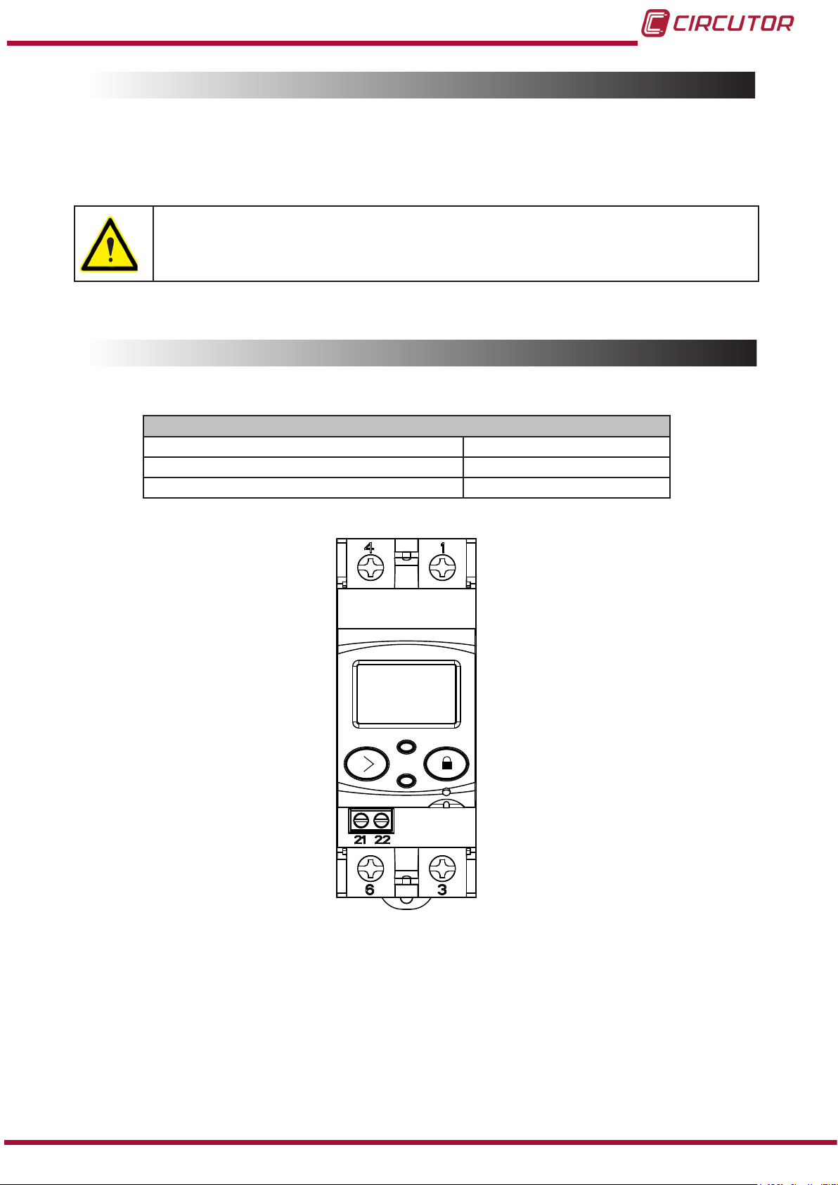
3.3.- UNIT TERMINALS
Table 3:List of CEM-C10 terminals�
Unit terminals
1 : L, Input, connected to the mains phase 6: LOAD, Output
3: LOAD, Output 21: impulse output (Collector)
4: N, Input, connected to neutral 22: Impulse output (Emitter)
Instruction Manual
Figure 1:Terminals of the CEM-C10�
9
Page 10
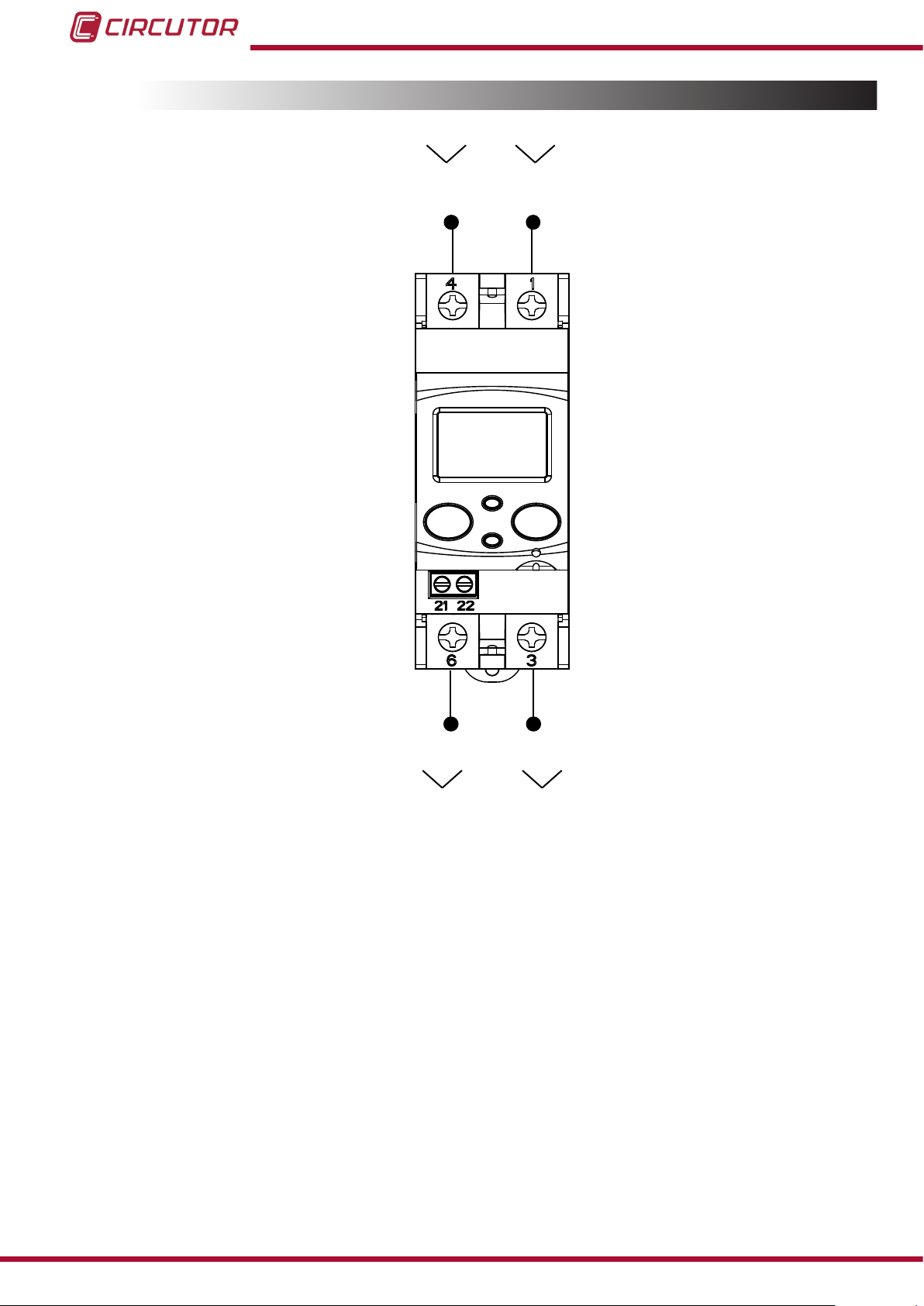
3.4.- CONNECTION DIAGRAM
CEM-C10
IN
N
L
LOAD
OUT
Figure 2: Connection diagram, CEM-C10�
10
Instruction Manual
Page 11
CEM-C10
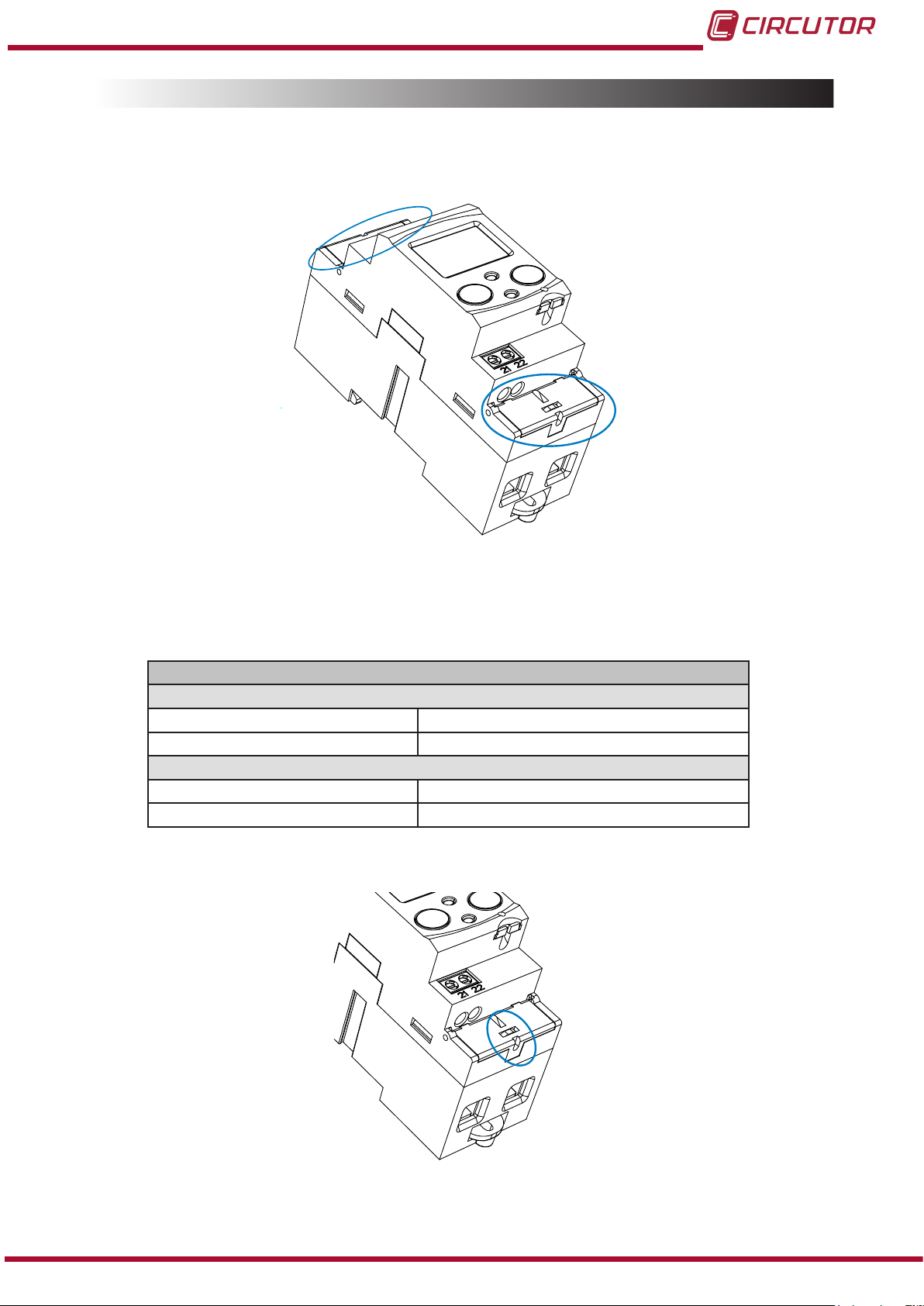
3.5.- CONNECTIONS
The CEM-C10 has terminal covers to cover the top of the terminal box and the xing screws
(Figure 3).
Figure 3: Terminal covers of the CEM-C10�
The xing screws are of the mixed type, allowing the use of PZ2 and at head screwdrivers.
Table 4:CEM-C10 connections�
Connections
Measurement terminals ( 1, 3, 4, 6)
Maximum cable cross-section 25 mm2 ( 16 mm2 with end sleeve) ≤ 1.2 Nm
Screwdrivers head PZ2
Impulse output terminals ( 21, 22 )
Maximum cable cross-section 1.5 mm2 ( 1.5 mm2 with end sleeve ) ≤ 0.6 Nm
Screwdrivers head at head ( 3 x 0.5 mm)
Once connected, the unit can be protected with two connection seals ( Figure 4).
Instruction Manual
Figure 4: Seal of the CEM-C10�
11
Page 12

CEM-C10
4�- OPERATION
The CEM-C10 is an energy meter capable of measuring:
Imported and exported active energy and reactive energy in the four quadrants.
(according to version).
Active and reactive power (according to version).
RMS voltage and current
Power factor, PF
4.1.- KEYBOARD FUNCTIONS
The CEM-C10 has 1 key that allows you to browse the different screens and congure the unit.
Key functions on the measuring screens (Table 5):
Table 5: Keys functions on measuring screens�
Key Short press
4.2.- DISPLAY
For the cyclic movement.
Next screen.
No function.
Enters reading mode.
The unit has an LCD where all parameters are displayed.
The display is divided into three areas (Figure 5):
Long press
(> 2 s)
12
Figure 5: CEM-C10 Display areas
Data line, displaying the values measured by the unit.
Instruction Manual
Page 13

CEM-C10
Units, where the unit of the magnitude being viewed is shown.
Indicators, which shows other parameters:
Indicates that the energy being viewed is generated.
Indicates that the energy being viewed is consumed.
Indicates that the energy is inductive.
Indicates that the energy is capacitive.
COM, indicates that there is a communications module connected. It ashes when the
communications are established.
L1 - L2 - L3 - Indicates the presence of voltage in each phase, with its corresponding
current direction:
“ - “ is used to show the power yielded to the network.
“ “ is used to show the power absorbed by the network.
4.3.- LED INDICATORS
The unit has two verication LEDs:
To verify the active energy�
To verify the reactive energy (according to version).
The weight of the LEDs is 1,000 imp/kWh(kvarh).
The LEDs will remain lit when the current lower than the energy meter start-up current. Once
the start-up current is exceeded (due to active or reactive power consumption) the LEDs are
turned off and emit impulses that are proportional to the measured energy.
Active LED
Instruction Manual
Reactive LED
Figure 6:LED Indicators of the CEM-C10�
13
Page 14

CEM-C10
4.4.- DISPLAY MODES
The CEM-C10 has 2 display modes:
Standby mode display
Reading mode display
4�4�1� STANDBY MODE DISPLAY
With the display in standby mode, all of the information is presented in cyclic form without any
need to perform any action on the CEM-C10 keyboard.
Six different parameters are viewed in this mode, see Table 6, in which they alternate every 6
seconds.
The unit is in this mode by default when none of the keys are pressed.
Short press the key to stop the cyclic movement of the parameter being shown at the time.
From then on, short press the key to browse all the parameters dened in Table 6.
Table 6: Standby mode displays
Screen Parameters
Total imported active energy
Total exported active energy
Only displayed in the 4-quadrant version.
Reactive energy quadrant L+ total
(1)
14
Reactive energy quadrant L- total
Only displayed in the 4-quadrant version.
Reactive energy quadrant C- total
Only displayed in the 4-quadrant version.
(1)
(1)
Instruction Manual
Page 15

CEM-C10
Table 6 ( Continuation ) : Standby mode displays
Screen Parameters
Reactive energy quadrant C+ total
(1)
Only displayed if the reactive energy display option has been selected in the setup menu. ( see
(1)
“4.7.6. Display”).
The standby mode is activated again when no key is pressed for 60 seconds.
Instruction Manual
15
Page 16

CEM-C10
4�4�2� READING MODE DISPLAY
The reading mode is activated by a long press on the key.
In reading mode you can:
View the voltage, current, active power, apparent power and power factor of the
installation.
View the energies of the partial energy meters.
Enter the programming menu.
View the manufacturer information.
The navigation diagram is shown in Figure 7:
16
Figure 7: Navigation diagram in reading mode of the CEM-C10�
NB: PC is a short press on the key (< 2 seconds).
PL is a long press ( > 2 seconds).
Instruction Manual
Page 17

CEM-C10
4.5.- INSTANTANEOUS VALUE DISPLAY
To open the screens where the instantaneous value are viewed, long press the key on the
display in standby mode.
The home screen is displayed Figure 8:
Figure 8: Instantaneous Value main screen�
Long press the key to open the different screens.
Short press the key to browse the different screens (see Table 7).
The standby mode is activated again when no key is pressed for 60 seconds.
Table 7: Instantaneous value screens
Screen Parameters
Voltage
Current
Active power
Reactive power
Instruction Manual
Apparent power
Power factor
17
Page 18

CEM-C10
Table 7 ( Continuation ) : Instantaneous value screens
Screen Parameters
Hours of operation from manufacture
4.6.- PARTIAL ENERGY DISPLAY
NB: The partial energy display menu is only displayed if the partial energy display option has
been selected in the setup menu ( see “4.7.6. Display” ).
Long press the key in the standby mode screen to open these display screens. Short press
the key to display the partial energy main screen, Figure 9:
Figure 9: Partial energy main screen�
Long press the key to open the different screens.
Short press the key to browse the different screens (see Table 8).
The PAR icon on the screen indicates that you are viewing the partial energies.
The standby mode is activated again when no key is pressed for 60 seconds.
Table 8:Partial energy screens�
Screen Parameters
Partial imported active energy.
Partial exported active energy.
Only displayed in the 4-quadrant version.
18
Partial reactive energy, quadrant 1 (L+).
Instruction Manual
(1)
Page 19

CEM-C10
Table 8 ( Continuation ) : Partial energy screens�
Screen Parameters
Partial reactive energy, quadrant 2 (L-).
(1)
Only displayed in the 4-quadrant version.
Partial reactive energy, quadrant 3 ( C-)
(1)
Only displayed in the 4-quadrant version.
Partial reactive energy, quadrant 4 (C+)
(1)
Hours in partial operation
(since the last partial reset )
Cost of the partial active energy consumed
(since the last partial reset )
(2)
CO2 emissions into the atmosphere.
(since the last partial reset )
(
1)
Only displayed if the reactive energy display option has been selected in the setup menu (see “4.7.6.
(2)
Display”).
(2)
Only displayed if the efciency factors display option has been selected in the setup menu (see
“4.7.6. Display”).
Instruction Manual
19
Page 20

CEM-C10
4.7.- CONFIGURATION
In the setup menu you can:
Program the weight and type of impulse output.
Program the communications.
Program the display screen.
Program the cost of the energy and the CO2. emissions
Delete the partial energy meters.
The standby mode is activated again when no key is pressed for 60 seconds.
Long press the key in the standby mode screen to open these setup screens. Short press
the key to display the home screen, Figure 10:
Figure 10: Programming home screen
Long press the key to access the rst programming step.
4�7�1� Impulse output weight
This is the home screen for entering the weight of the impulse
output.
Long press the key to view the value to be programmed.
To write or modify the value, short press the key repeatedly,
increasing the value of the ashing digit.
20
When the desired value is shown on the screen, move onto the next digit with a long press on
the key, allowing the remaining values to be modied.
To validate the data, move to the last digit and long press the key; the validation screen
will appear (Figure 11) indicating that the programming value has been saved.
Instruction Manual
Page 21

CEM-C10
Figure 11: Validation screen�
After a few seconds viewing the screen shown on Figure 11 , the system returns to the Impulse
output weight programming main screen.
Minimum value: 99999.
Maximum value: 0.
Short press the key to access the next programming step
4�7�2� Impulse output type
The impulse output type is selected on this screen, between:
kWh or KVArh�
Short press the
key to browse the different options.
To validate the data, long press the key and the validation screen will appear (Figure 11)
indicating that the programming value has been saved.
After a few seconds viewing the screen shown on Figure 11 , the system returns to the Impulse
output type programming main screen.
Short press the key to access the next programming step.
4�7�3� Peripheral address
NB : This is only displayed if there is a CEM M-RS485 (communications interface for the CEM
family of units) connected to the unit.
This is the home screen for entering the peripheral address.
Long press the key to view the value to be programmed.
Instruction Manual
21
Page 22

CEM-C10
To write or modify the value, short press the key repeatedly,
increasing the value of the ashing digit.
When the desired value is shown on the screen, move onto the next digit with a long press on
the key, allowing the remaining values to be modied.
To validate the data, move to the last digit and long press the key; the validation screen
will appear (Figure 11) indicating that the programming value has been saved.
After a few seconds viewing the screen shown on Figure 11 , the system returns to the
Peripheral address programming main screen.
Minimum value: 1.
Maximum value: 254
Short press the key to access the next programming step
4�7�4� Transmission speed ( Baud rate)
NB: This is only displayed if there is a CEM M-RS485 (communications interface for the CEM
family of units) connected to the unit.
This is the home screen for entering the transmission speed.
Long press the key to view the value to be programmed.
The transmission speed (Baud rate) is selected on this screen,
and may be: 9600, 19200 or 38400�
Short press the
key to browse the different options.
22
To validate the data, long press the key and the validation screen will appear (Figure 11)
indicating that the programming value has been saved.
After a few seconds viewing the screen shown on Figure 11, the system returns to the
Transmission speed programming main screen.
Short press the key to access the next programming step.
Instruction Manual
Page 23

CEM-C10
4�7�5� Type of communications
NB: This is only displayed if there is a CEM M-RS485 (communications interface for the CEM
family of units) connected to the unit.
This is the home screen for selecting the number of bits, the
parity and the number of stop bits of the communications frame.
Long press the key to view the value to be programmed.
This screen shows the different options:
8n1 : 8 bits, no parity, 1 stop bit.
8E1 : 8 bits, even parity, 1 stop bit.
8o1 : 8 bits, odd parity, 1 stop bit.
8n2 : 8 bits, no parity, 2 stop bits.
8E2 : 8 bits, even parity, 2 stop bits.
8o2 : 8 bits, odd parity, 2 stop bits.
Short press the key to browse the different options.
To validate the data, long press the key and the validation screen will appear (Figure 11)
indicating that the programming value has been saved.
After a few seconds viewing the screen shown on Figure 11 , the system returns to the
Communications type programming main screen.
Short press the key to access the next programming step.
4�7�6� Display
This is the home screen for selecting the unit display options.
Long press to access the partial energy display selection screen:
4�7�6�1� Partial energy display
This is the home screen for selecting the partial energy display
view option.
Instruction Manual
23
Page 24

Long press to view the options.
The possible options are:
Yes, if you want to view the partial energy.
No, if you select this option, the unit stops recording the partial
energy. A display view is not provided and the value displayed by
communications is 0.
CEM-C10
Para saltar entre las diferentes opciones pulsar la tecla de
pulsaciones cortas.
con
To validate the data, long press the button. The unit will return to the main programming
screen of the Partial energy display.
Short press to access the reactive energy display selection screen:
4�7�6�2� Reactive energy display
This is the home screen for selecting the reactive energy log
display view option.
Long press to view the options.
The possible options are:
Yes, if you want a display view of the reactive energy screens.
No, a display view of the reactive energy screens is not provided,
but a communications view is possible.
Short press the
button to browse the different options.
To validate the data, long press the button. The unit will return to the main programming
screen of the Reactive energy display.
Short press to access the efciency factors display selection screen:
4.7.6.3. Efciency factors display
This is the home screen for selecting the display view of the
efciency factors: Cost of energy and CO2 emissions.
Long press to view the options.
24
Instruction Manual
Page 25

CEM-C10
The possible options are:
Yes, if you want a display view of the efciency screens (cost of
energy and CO2 emissions).
No, if you select this option, the unit stops recording the efciency
factors. A display view is not provided and the value displayed by
communications is 0.
Short press the
button to browse the different options.
To validate the data, long press the button. The unit will return to the main programming
screen of the Efciency factors display.
Short press to access the display menu output screen:
When this screen is displayed:
Short press the
button to return to the rst conguration
point of the display ( “4.7.6.1. Partial energy display“)
Long press the
button to jump to the next programming
point.
4�7�7� Backlight
This is the home screen for selecting the backlight operating mode
of the screen in those units that feature it.
Long press to view the different options:
This screen shows the different options:
On : Backlight always ON.
Off : Backlight always OFF.
005 SEC ... 120 SEC: ON time after the last press of the buttons.
Short press the button to browse the different options.
To validate the data, long press the button and the validation screen will appear (Figure
11) indicating that the programming value has been saved.
After a few seconds viewing the screen shown in Figure 11 , it returns to the main programming
screen of the Backlight.
Short press the .button to access the next programming step.
Instruction Manual
25
Page 26

4�7�8� Energy cost
NB: It is only displayed if the efciency factors display has been selected.
This is the home screen for entering the energy cost per kWh.
Long press the key to view the value to be programmed.
To write or modify the value, short press the key repeatedly,
increasing the value of the ashing digit.
CEM-C10
When the desired value is shown on the screen, move onto the next digit with a long press on
the key, allowing the remaining values to be modied.
To validate the data, move to the last digit and long press the key; the validation screen
will appear (Figure 11) indicating that the programming value has been saved.
After a few seconds viewing the screen shown on Figure 11 , the system returns to the Energy
cost programming main screen.
Minimum value: 0.000
Maximum value: 9999.999
Short press the key to access the next programming step.
4�7�9� CO2 emissions
NB: It is only displayed if the efciency factors display has been selected.
This is the home screen for entering the ratio of the carbon
emissions.
The carbon emissions ratio is the amount of emissions released
into the atmosphere to produce a unit of electricity (1 kWh).
The European mix ratio is approximately 0.65 kgCo2 per kWh.
26
Long press the key to view the value to be programmed.
Instruction Manual
Page 27

CEM-C10
To write or modify the value, short press the key repeatedly,
increasing the value of the ashing digit.
When the desired value is shown on the screen, move onto the next digit with a long press on
the key, allowing the remaining values to be modied.
To validate the data, move to the last digit and long press the key; the validation screen
will appear (Figure 11) indicating that the programming value has been saved.
After a few seconds viewing the screen shown on Figure 11, the system returns to the CO2
emissions programming main screen.
Minimum value: 0.000
Maximum value: 9.000
Short press the key to access the next programming step.
4�7�10� Deleting the partial energy meters
NB: It is only displayed if the partial energy display has been selected.
On this screen you select whether or not to delete the partial
energy meters.
Long press the
validation screen (
key to delete the energy meters. The
Figure 11) will be displayed next, indicating that
the energy meters were deleted correctly.
After a few seconds viewing the screen shown on Figure 11 , the system returns to the Partial
energy meter deletion programming main screen.
4�7�11� Exiting the setup menu
When this screen is displayed:
Instruction Manual
Long press the
Short press the
Impulse output weight”
key to exit the setup menu.
key to return to the rst setup point ( “4.7.1.
).
27
Page 28

CEM-C10
4.8.- MANUFACTURER INFORMATION SCREEN
Long press the key in the standby mode screen to open these display screens. Short press
the key to display the manufacturer information home screen, Figure 12:
Figure 12: Manufacturer information home screen�
Long press the key to open the different screens.
Short press the key to browse the different screens (see Table 9).
The standby mode is activated again when no key is pressed for 60 seconds.
Table 9: Manufacturer information screens�
Screen Parameters
Unit model
Version
Communications protocol
Communications protocol
version
(1)
(1)
28
Active energy with resolution in Wh
Reactive energy with resolution varh
Instruction Manual
Page 29

CEM-C10
Table 9 ( Configuration ) : Manufacturer information screens�
Screen Parameters
(1)
The screen is displayed if there is a CEM M-RS485 (communications interface for units of the CEM
family) connected to the unit.
4.9.- IMPULSE OUTPUT
32-bit CRC (high and low-order)
The energy meter has optocoupler type outputs capable of generating impulses at a previously
programmed rate. (See “4.7.1. Impulse output weight” and ”4.7.2. Impulse output type” )
4.10.- INFRARED COMMUNICATIONS PORT.
In all versions, the unit has a serial optical communications port, in compliance with the UNE
EN 62056-21:2003 Standard.
Instruction Manual
29
Page 30

5�- TECHNICAL FEATURES
Power supply
Mode Self-powered
Rated voltage 230 V or 127 V ~ according to version
Tolerance ± 20 %
Frequency 50...60 Hz
CEM-C10
Consumption
Voltage Measurement
Connection Single-phase
Reference voltages 230 V or 127 V ~ according to version
Frequency 50 or 60Hz
Self-consumption of the voltage circuit
Current measurement
S7 S4
Current (Ib / Iref) 5 A 10 A
Maximum current (Imax) 65A 60 A
Starting current < 0.1% of In < 0.1% of In
Self-consumption of the current circuit 0.3 VA @ 10 A 0.3 VA @ 10 A
Itr 0.500 A 1.000 A
Ist 0.020 A 0.040 A
Imin 0.250 A 0.500 A
Maximum overcurrent time
( 30xImax) ( according to EN-50470-3)
< 10VA (In, Vref (without auxiliary services))
< 10VA (In, Vref (without auxiliary services))
50Hz 60Hz 50Hz 60Hz
10 ms 8 ms 10 ms 8 ms
< 2 W
< 2 W
Accuracy
Active Energy
Reactive Energy Class 2.0 (IEC 62053-23)
Insulation
Alternating voltage 4kV RMS 50Hz during 1 minute
Over pulse
1�2/50ms 0R source impedance 6 kV at 60º and 240º, with positive and negative polarization
Calculation and processing
Microprocessor 16-bit RISC
AD converter 16-bit
Impulse output
Type Optocoupler
Operation Emission of impulses proportional to the energy
Electrical features Max. 24V 50mA
Impulse ON/OFF time 40 ms
Programmed weight of the impulse 10 Wh / impulso
No� of maximum impulses per second 12
CEM-C10 MID CEM-C10
Class B (EN 50470) Class 1 (IEC 62053-21)
30
Instruction Manual
Page 31

CEM-C10
IR port (service port)
Hardware EN62056-21
Protocol Modbus
Baud rate 9600
Stop bits 1
Parity no parity
User interface
Display LCD
Maximum counter value 999999.9 kWh
Keys 2 keys
LED
Environmental features
Operating temperature -25ºC... +70ºC
Storage temperature -35ºC... +80ºC
Relative humidity (non-condensing) 5 ... 95%
Maximum altitude 2,000 m
2 LEDs: kWh, 1000 imp/kWh
kvarh, 1000 imp/kvarh
Mechanical features
Dimensions ( Figure 13) IEC60715
Weight 140 g
Enclosure EN50022
Protection degree
90
35
5 44
35.5
IP 51 installed
IP40 in terminal area
61
45
65
Instruction Manual
Figure 13: Dimensions of the CEM-C10�
31
Page 32

Standards
Electrical energy metering equipment (AC)� Part 1: General requirements, tests and test conditions� Metering equipment (indexes of classes A, B and C)
Electrical energy metering equipment (AC)� Part 3: Particular require-
ments. Static active energy meters (classication indexes A, B and C).
Electrical energy metering equipment (AC)� Particular requirements�
Part 21: Static active energy meters (classes 1 and 2)
Electricity metering equipment (a�c�) - Particular requirements�
Part 23: Static meters for reactive energy (classes 2 and 3)�
CEM-C10
UNE EN 50470-1:2007
UNE EN 50470-3:2007
IEC 62053-21:2003
IEC 62053-23:2003
32
Instruction Manual
Page 33

CEM-C10
6�- MAINTENANCE AND TECHNICAL SERVICE
In the case of any query in relation to unit operation or malfunction, please contact the
CIRCUTOR, SA Technical Support Service.
Technical Assistance Service
Vial Sant Jordi, s/n, 08232 - Viladecavalls (Barcelona)
Tel: 902 449 459 ( España) / +34 937 452 919 (outside of Spain)
email: sat@circutor.es
7�- GUARANTEE
CIRCUTOR guarantees its products against any manufacturing defect for two years after the
delivery of the units.
CIRCUTOR will repair or replace any defective factory product returned during the guarantee
period.
• No returns will be accepted and no unit will be repaired or replaced if it is not accompanied by a report indicating the defect detected or the reason for the return.
•The guarantee will be void if the units has been improperly used or the storage, installation and maintenance instructions listed in this manual have not been
followed. “Improper usage” is de ned as any operating or storage condition contrary to the national electrical code or that surpasses the limits indicated in the
technical and environmental features of this manual.
• CIRCUTOR accepts no liability due to the possible damage to the unit or other
parts of the installation, nor will it cover any possible sanctions derived from a possible failure, improper installation or “improper usage” of the unit. Consequently,
this guarantee does not apply to failures occurring in the following cases:
- Overvoltages and/or electrical disturbances in the supply;
- Water, if the product does not have the appropriate IP classi cation;
- Poor ventilation and/or excessive temperatures;
- Improper installation and/or lack of maintenance;
- Buyer repairs or modi cations without the manufacturer’s authorisation.
Instruction Manual
33
Page 34

8�- CE CERTIFICATE
CEM-C10
34
Instruction Manual
Page 35

CEM-C10
Instruction Manual
35
Page 36

CIRCUTOR, SA
Vial Sant Jordi, s/n
08232 -Viladecavalls (Barcelona)
Tel.: (+34) 93 745 29 00 - Fax: (+34) 93 745 29 14
www.circutor.es central@circutor.es
 Loading...