

Page 1
Dynamic power control
CDP- 0, CDP- G
INSTRUCTION MANUAL
(M98250001-03-15A)
Page 2

CDP
2 Instruction Manual
Page 3
CDP
Incorrect handling or installation of the unit may result in injury to personnel as well
Consult the instruction manual b efore using the unit
SAFETY PRECAUTIONS
Follow the warnings described in this manual with the symbols shown below.
DANGER
Warns of a risk, which could result in personal injury or material damage
.
ATTENTION
Indicates that special attention should be paid to a specific point.
If you must handle the unit for its installation, start-up or maint e nance, the following should be taken into consideration:
as damage to the unit. In particular, handling with voltage applied may result in electric shock, which may cause death or serious injury to personnel. Defective inst allation or maintenance may also lead to the risk of fire.
Carefully read the manual prior to connecting the unit. Follow all installation and
maintenance instructions throughout the unit's working life. Pay special attention to
the installation standards of the National Electrical Code.
In this manual, if the instructions marked with this symbol are not respected or carried out correctly, it can result in injury or damage to the unit and /or installations
CIRCUTOR, SA reserves the right to modify features or the product manual without prior notification.
DISCLAIMER
CIRCUTOR, SA
reserves the right to make modifications to the device or the
unit specifications set out in this instruction manual without prior notice.
CIRCUTOR, SA
, on its web site, supplies its customers with the latest versions
of the device specifications and the most updated manuals.
www.circutor.com
.
Instruction Manual 3
Page 4

CDP
CONTENTS
SAFETY PRECAUTIONS .................................................................................................................... 3
DISCLAIMER ........................................................................................................................................ 3
CONTENTS .......................................................................................................................................... 4
LOG OF REVISIONS ........................................................................................................................... 6
1.- VERIFICATION UPON RECEIPT .................................................................................................. 7
2.- PRODUCT DESCRIPTION ............................................................................................................ 7
3.- INSTALLATION OF THE UNIT ...................................................................................................... 8
3.1.- PRELIMINARY RECOMMENDATIONS ......................................................................................8
3.2.- INSTALLATION...............................................................................................................................9
3.3.- LASER MARKING ..........................................................................................................................9
3.4.- UNIT TERMINALS .......................................................................................................................10
3.5.- CONNECTION DIAGRAMS .......................................................................................................11
3.5.1. AUXILIARY POWER SUPPLY ............................................................................................11
3.5.2. COMMUNICATIONS CONNECTION .................................................................................11
3.5.3. VOLTAGE MEASUREMENT AND CURRENT CONNECTION .....................................14
4.- OPERATION .................................................................................................................................. 15
4.1.- OPERATING PRINCIPLE ...........................................................................................................15
4.1.1. DESCRIPTION OF THE MEASUREMENT SYSTEM .....................................................15
4.1.2. OPERATION OF THE GRID INJECTION PROTECTION RELAY.................................15
4.1.3. MANAGEMENT OF NON-CRITICAL LOADS (CDP-G Model) ......................................19
4.2.- APPLICATIONS ............................................................................................................................21
4.2.1. BASIC SINGLE-PH A SE C ON NEC T I O N ...........................................................................21
4.2.1.1. Voltage connection ............................................................................................................21
4.2.1.2. Current connection ............................................................................................................22
4.2.2. SINGLE-PHASE CONNECTION WITH MONITORING ..................................................22
4.2.2.1. Voltage connection ............................................................................................................23
4.2.2.2. Current connection ............................................................................................................23
4.2.3. BASIC THREE-PHASE CONNECTION ............................................................................23
4.2.4. THREE-PHASE CONNECTION WITH MONITORING ...................................................24
4.3.- OPERATING EXAMPLES FOR THE CDP-G MODEL ............................................................25
4.3.1. SINGLE-PHASE INSTALLATION WITH 1 LOAD TO BE CONNECTED .....................25
4.3.2. SINGLE-PHASE INSTALLATION WITH 3 LOADS TO BE CONNECTED ...................28
4.4.- KEY FUNCTIONS ........................................................................................................................34
4.5.- LED INDICATORS .......................................................................................................................35
4.6.- DISPLAY ........................................................................................................................................36
5.- DISPLAY AND CONFIGURATION .............................................................................................. 38
5.1. MEASURES MENU ......................................................................................................................38
5.2. NETWORK MENU ........................................................................................................................41
5.2.1. DHCP ASSIGNMENT ...........................................................................................................42
4 Instruction Manual
Page 5

CDP
5.2.2. DHCP OPTION: YES ............................................................................................................43
5.2.3. DHCP OPTION: NO ..............................................................................................................43
5.3. SYSTEM MENU ............................................................................................................................45
6.- COMMUNICATIONS..................................................................................................................... 46
6.1. CONFIGURATION WEB SITE .....................................................................................................46
6.1.1. CDP Setup..............................................................................................................................48
6.1.2. Power control & Data logger ................................................................................................50
6.1.2.1. Inverter ................................................................................................................................50
6.1.2.2. Control .................................................................................................................................51
6.1.2.3. Inverse current relay ..........................................................................................................54
6.1.2.4. Auxiliary load relays ...........................................................................................................54
6.1.2.5. Data logger .........................................................................................................................56
6.1.3. Analyzers setup .....................................................................................................................56
6.1.4. Network & Security Setup ....................................................................................................57
6.1.5. Save setup, Load default setup and Reset CDP ..............................................................58
6.2. DISPLAY WEB SITE .....................................................................................................................60
6.2.1. CDP AS A DATA LOGGER ..................................................................................................61
7.- TECHNICAL FEATURES ............................................................................................................. 67
8.- MAINTENANCE AND TECHNICAL SERVICE .......................................................................... 69
9.- GUARANTEE ................................................................................................................................ 69
10.- CE CERTIFICATE ....................................................................................................................... 70
APPENDIX A: M O DBUS MAP ......................................................................................................... 71
Instruction Manual 5
Page 6

CDP
Date
Revision
Description
M98250001-03-13A
Original version
07/14
M98250001-03-14A
General revision
09/14
M98250001-03-14B
Introduction model CDP-G
Changes in the following sections:
6.1.2.3.- 6.1.2.5.- 6.1.5. – Appendix A
LOG OF REVISIONS
Table 1: Log of revisions.
01/15 M98250001-01-15A
3.5.2.- 4.1.2.- 4.6.- 5 – 5.2.- 5.3. -6.1.1.- 6.1.2.1.-
Note: The images of the units are solely for the purpose of illustration and may
differ from the original uni t.
6 Instruction Manual
Page 7
CDP
1.- VERIFICATION UPON RECEIPT
Check the following points when you receive the unit:
a) The unit meets the specifications described in your order.
b) The unit has not suffered any damage during transport.
c) Perform an external visual inspection of the unit prior to switching it on.
d) Check that it has been deliv ered w i th the foll owing:
- An installation guide.
If any problem is noticed upon reception, immediately contact the
transport company and/or CIRCUTOR's after-sales service.
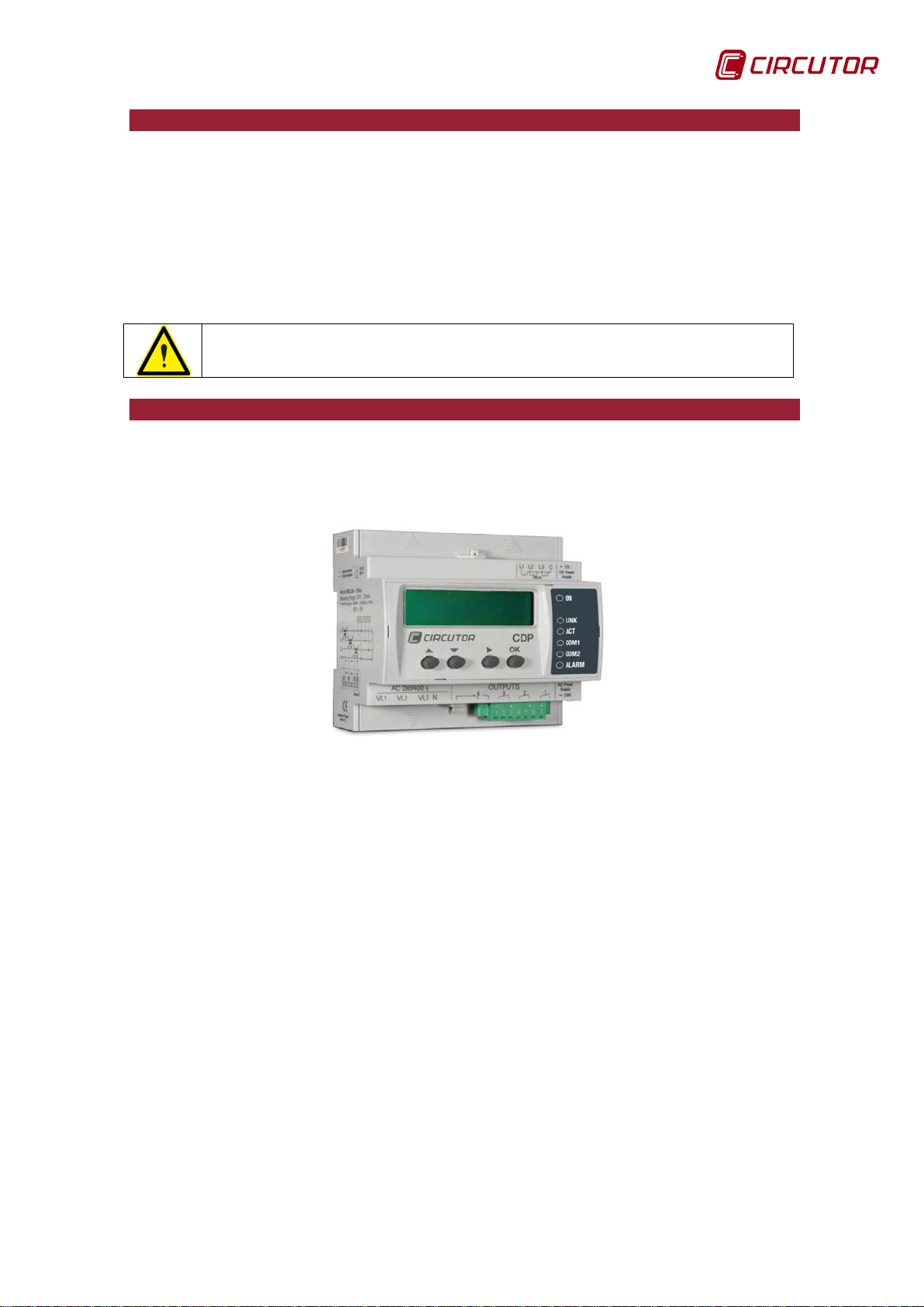
2.- PRODUCT DESCRIPTION
CDP units are a family of dynamic power controllers that shift the operating point
of the solar field, enabling regulation of the inverter's generation level based on
user consumption.
The unit features:
-1 Ethernet communications channel for Online monitoring from any PC or
mobile device with a web browser.
- 20-character, 2-line display for viewing all the electric variables measured by
the unit.
- 6 indicator LEDs indicating the communications and alarm status in real time.
- 4 keys to browse the menu.
The CDP-G model can manage up to 3 non-critical loads.
Instruction Manual 7
Page 8
CDP
In order to use the unit safely, it is critical that individuals who handle it
Disconnect the unit from the power supply (unit and measuring system
3.- INSTALLATIO N OF THE UNIT
3.1.- PRELIMINARY RECOMMENDATIONS
follow the safety measures set out in the standards of the country
where it is being used, use the necessary personal pr ot ecti ve equipment, and pay attention to the various warnings indicated in this instruction manual.
The
The power supply plug must be disconnected and measuring systems switched
off before handling, altering the connections or replacing the unit. It is dangerous
to handle the unit while it is powered.
Also, it is critical to keep the cables in perfect condition in order to avoid accidents, personal injury and damage to installations.
The manufacturer of the unit is not responsible for any damage resulting from
failure by the user or installer to observe the warnings and/or recommendations
set out in this manual, nor for damage resul ting from the use of non-original
products or accessories or those made by other manufacturers.
If an anomaly or malfunction is detected in the unit, do not use the unit to take
any measurements.
Inspect the work area before taking any measurements. Do not take measurements in dangerous areas or where there is a risk of explosion.
unit must be installed by author i sed and qual ified staff.
CDP
power supply) before maintaining, repairing or handling the unit's connections.
Please contact the after-sales service if you suspect that there is an
operational fault in the unit .
8 Instruction Manual
Page 9
CDP
Terminals, opening covers or removing elements can expose parts that
are hazardous to the touch while the unit is powered. Do not use the
3.2.- INSTALLATION
Install the unit on a DIN 46277 rail (EN 50022). All connections are located
inside the electric panel.
unit until it is fully installed.
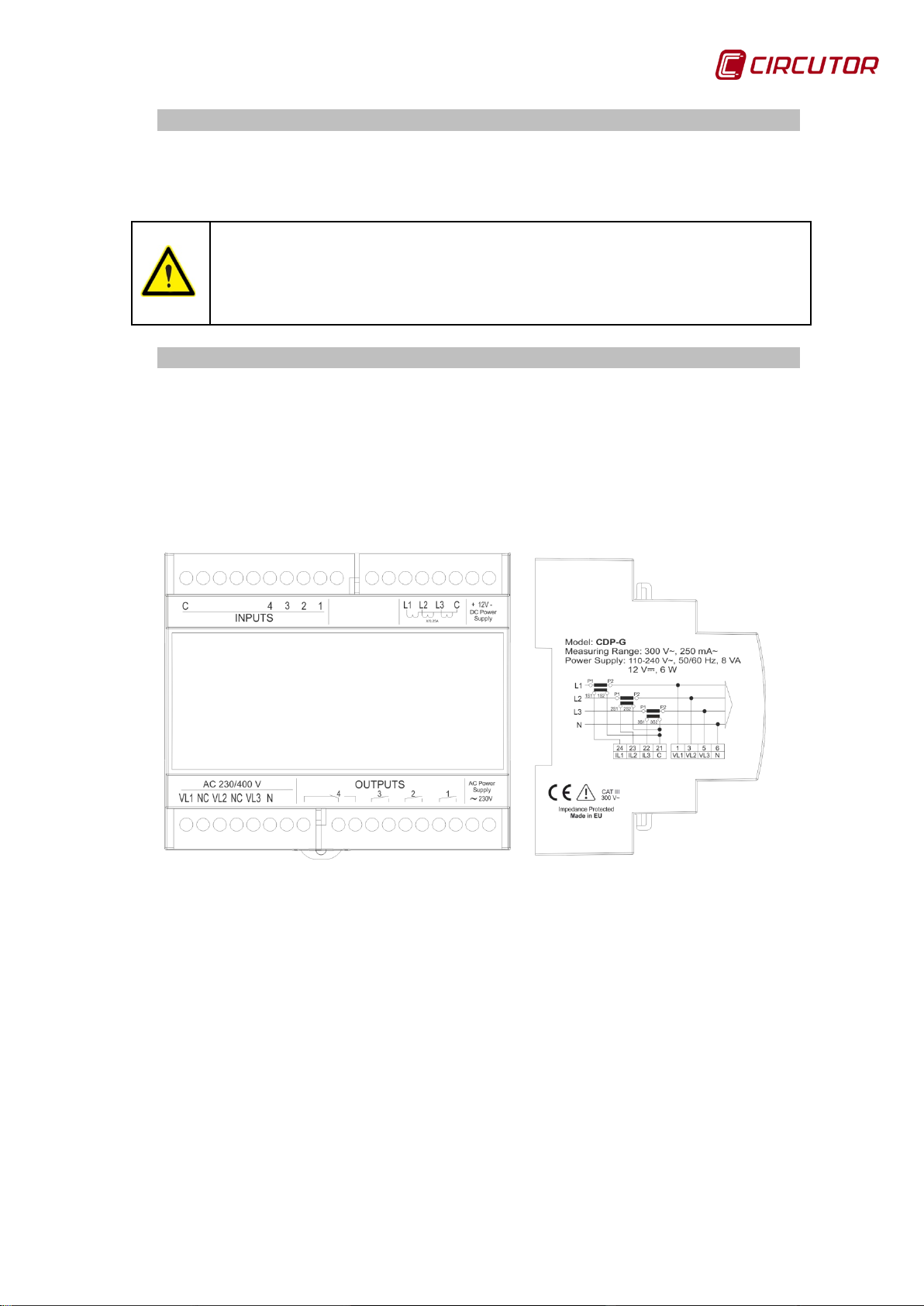
3.3.- LASER MARKING
The front view of the CDP shows that the numerical identification of the terminals
and symbols associated with their features have been marked with a laser.
The side view shows the electrical features of the unit and a diagram of its
single-phase connection, illustrating the user, grid and inverter power
measurement connection.
Figure 1: Description of the laser marking.
Instruction Manual 9
Page 10
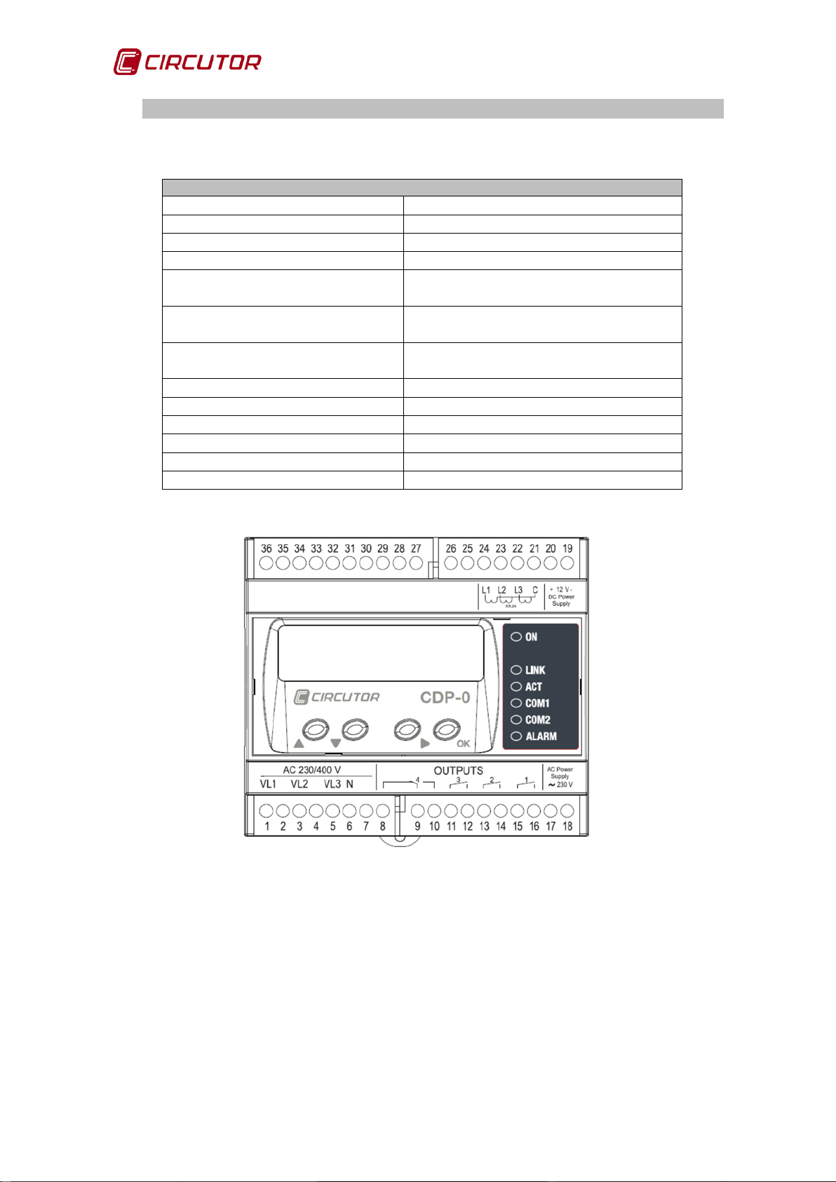
CDP
Unit terminals
1: Voltage measurement VL1
17: Auxiliary power supply
3: Voltage measurement VL2
18: Auxiliary power supply
5: Voltage measurement VL3
19: DC Auxiliary power supply (-)
6: Voltage measurement neutral
20: DC Auxiliary power supply (+)
8: Inverse current relay 4 /
Auxiliary relay 4 (NC)
9: Inverse current relay 4 /
Auxiliary relay 4 (COM)
10: Inverse current relay 4 /
Auxiliary relay 4 (NO)
11: Auxiliary relay 3
24: L1 current measurement
12: Auxiliary relay 3
28: Digital input 1
13: Auxiliary relay 2
29: Digital input 2
14: Auxiliary relay 2
30: Digital input 3
15: Auxiliary relay 1
31: Digital input 4
16: Auxiliary relay 1
36: Digital inputs common
3.4.- UNIT TERMINALS
Table 2: List of CDP terminals.
21: Current measurement common
22: L3 current measurement
23: L2 current measurement
Figure 2: CDP terminals
10 Instruction Manual
Page 11
CDP
Equivalence between the single-phase and three-phase connection
Connection
Single-phase connection
Three-phase connection
VL1 – IL1
User consumption
Phase 1 consumption
VL2 – IL2
Consumption from the grid
Phase 2 consumption
VL3 – IL3
Power injected by the inverter
Phase 3 consumption
AC power supply
DC power supply
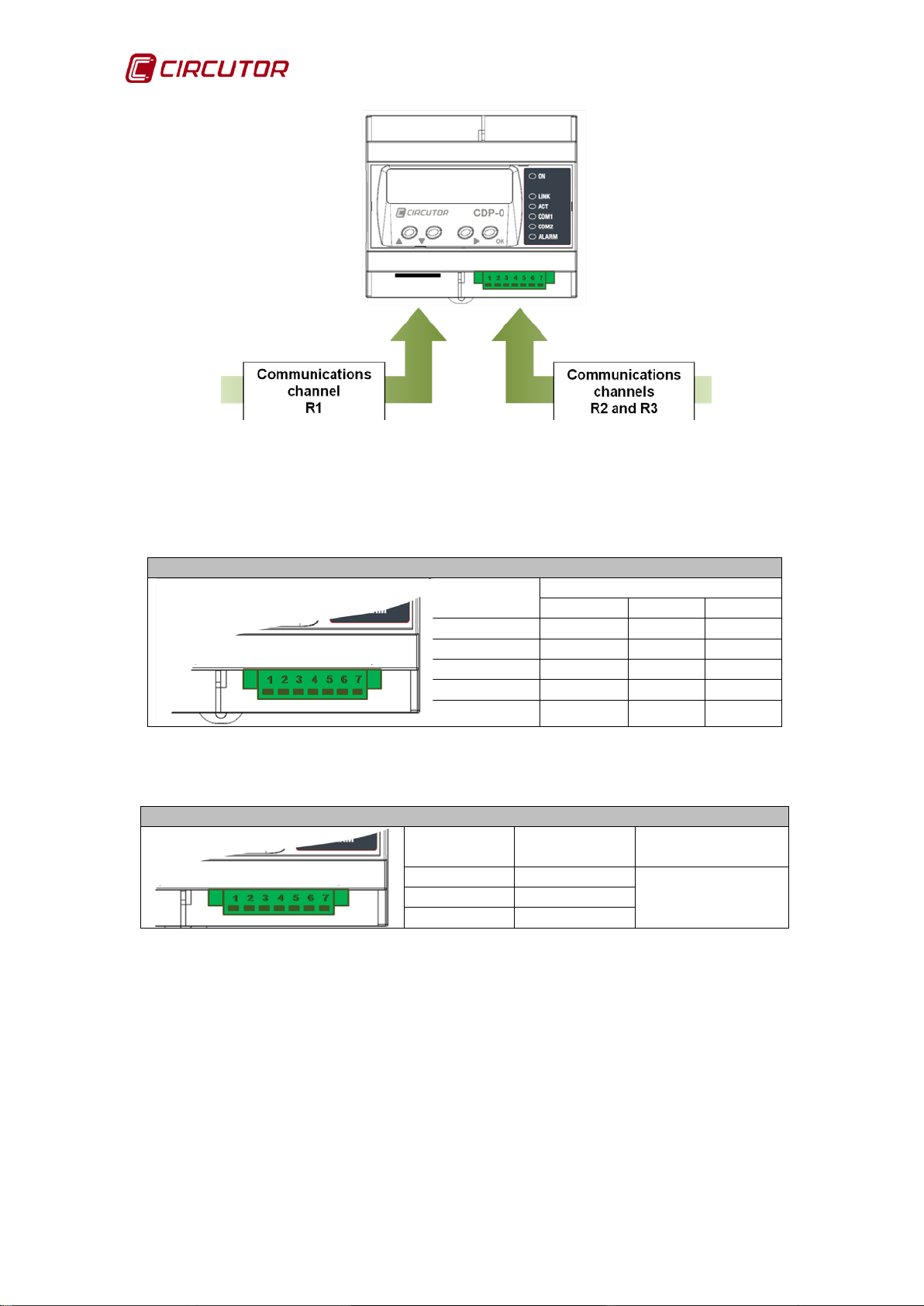
Description of the communications channels
Channel
Description of the channel
R1
Ethernet communications channel
Channel for communicating with the inverter:
RS422/RS485/RS232
Channel for communicating with the external measuring parts:
RS485
3.5.- CONNECTION DIAGRAMS
Table 3: Equivalences between the single-phase and three-phase connection.
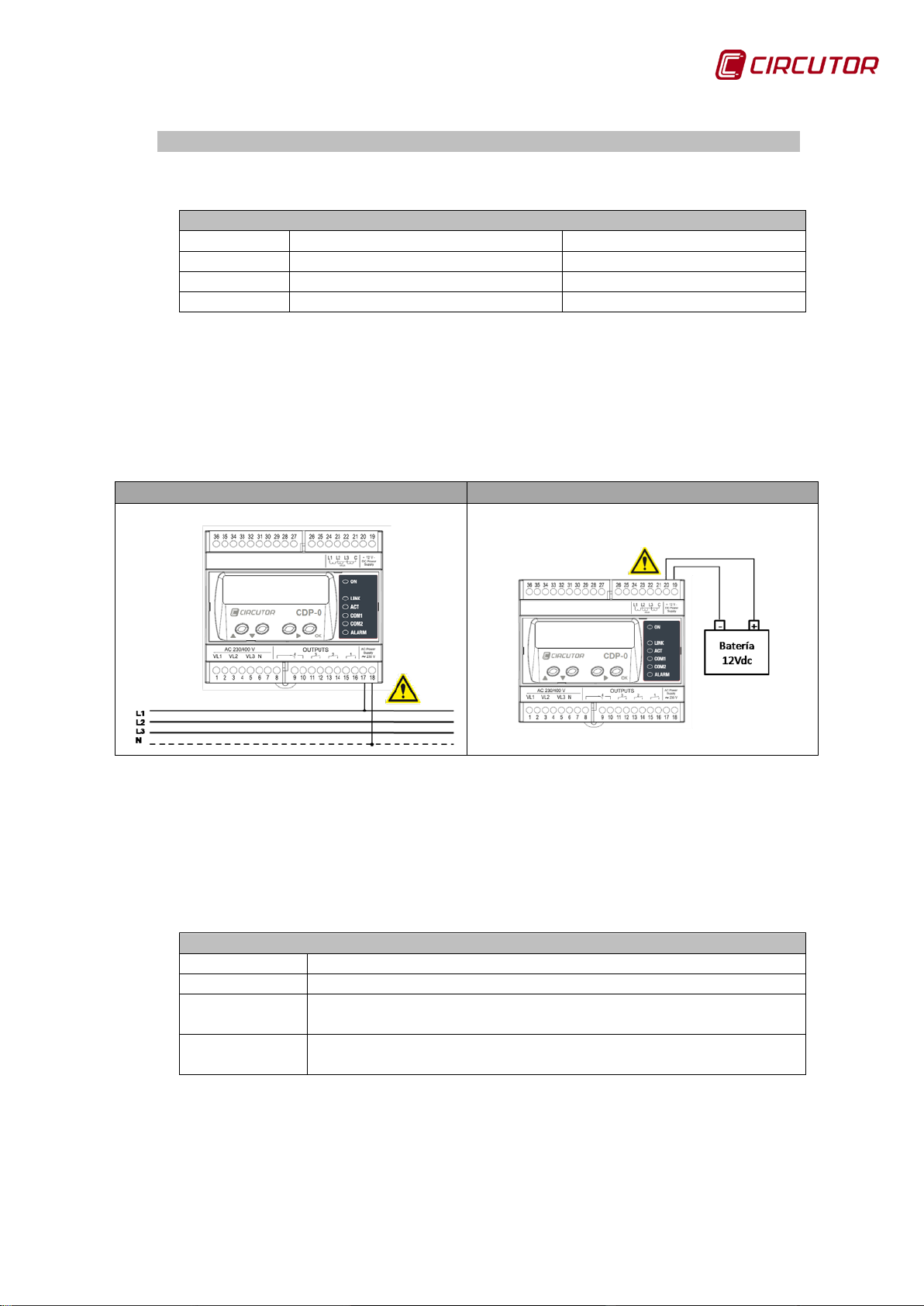
3.5.1. AUXILIARY POWER SUPPLY
The unit has terminals for supplying it either AC voltage (17-18) or DC voltage
(19-20):
Figure 3: AC and DC power supply connection.
3.5.2. COMMUNICATIONS CONNECTION The CDP has three communications channels referred to as R1, R2 and R3.
Table 4: Des cription of the communications channels.
R2
R3
Instruction Manual 11
Page 12
CDP
Description of the R2 communications channel connector
Description of terminal
RS-422
RS-485
RS-232
1
TxD +
A+
CTS
2
RxD –
NC
(1)
RTS
3
TxD -
B-
RX
4
RxD +
NC
(1)
TX
GND
GND
GND
Description of the R3 communications channel connector
Description
of terminal
Communication
s channel
5
GND
6
B- 7 A+
Figure 4: Communications channels.
The removable connector terminals are described as follows:
Table 5: Description of the R2 channel terminals.
Terminals
5
(1)
NC: Not connected.
Table 6: Des cription of the R3 channel terminals.
Terminals
RS-485
The R2 channel is used for communications with the inverter and the R3 to
create a network with the auxiliary units that help measure the power in threephase installations.
Note: For the proper working of RS-485 communications, always connect the
GND terminal.
12 Instruction Manual
Page 13
CDP
Correspondence between the CDP and CVM Mini connection
CDP
CVM MINI
Terminal
Description
Terminal
Description
5
GND
2
GND
6
B- 1 B-
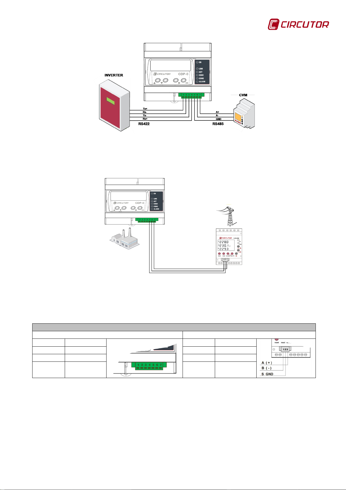
Figure 5: Communications with the inverter and the CVM Mini.
Connection diagram fo r CDP communications with the external CVM Mini:
Figure 6: CDP connection with the external CVM Mini.
Table 7: Connection of communications between the CDP and the CVM Mini.
7 A+ 3 A+
To ensure that the CDP can communicate with the external CVM Mini, this must
be configured as per Table 8:
Instruction Manual 13
Page 14
CDP
Configuration of the external CVM Mini.
Parameter
Value
Peripheral number
Configurable
Bauds
Configurable
Bits
8
Parity
NO
Stop bits
1 Stop bit
Transformer models
MC3 – three-phase
transformer
Models:
chosen ratio in the measuring unit.
Table 8: Configuration of the external CVM Mini.
It is recommended that a category 5e FTP cable or higher is used and a twisted
pair must be used for each earth leakage signal pair.
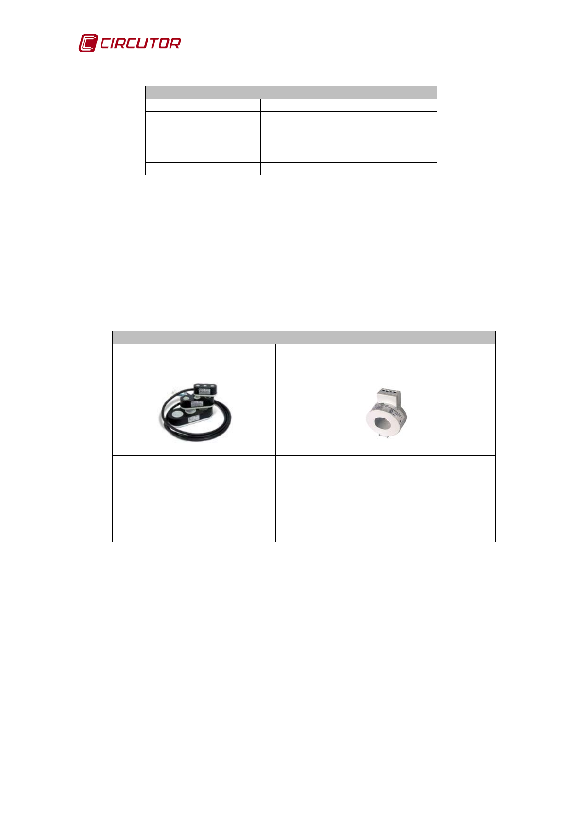
3.5.3. VOLTAGE MEASUREMENT AND CURRENT CONNECTION
The CDP measures current using the MC1 or MC3 transformers with a
secondary current of 250 mA
Table 9: Current measurement transformer models.
MC1- 1 transformer per phase
Models 63, 125 and 250 A.
150/200/250A, 250/400/500A,
50/100/150A, 500/1000/1500A,
1000/1500/2000 A
Each transformer has 3 ratio ranges,
changing a connection cable and the
14 Instruction Manual
Page 15

CDP
4.- OPERATION
4.1.- OPERATING PRINCIPLE
One of the main features of the CDP is that it can measure all the energy flows
of the installation:
Energy consumed by the user.
Energy generated by the inverter.
Energy consumed or injected into the grid.
The inverter power must be configured in the unit and, through a
communications channel, the CDP can adapt generation to energy consumption
with the aim of achieving zero grid injection
The CDP generates a database with all the power and energy information for
every measuring point, including the inverter's regulation percentage.
The following functions have also been implemented in the CDP:
• Grid injection alarm control.
• Management of non-critical loads, CDP-G model.
4.1.1. DESCRIPTION OF THE MEASUREMENT SYSTEM
The CDP measures the user's voltage and current and uses these values to
calculate the consumed power. If the power generated by the inverter differs
from that consumed, the unit changes the inverter's working setpoint to adjust it
to the real-time needs o f the inst al lat ion.
4.1.2. OPERATION OF THE GRID INJ ECTION PROTECTION RELAY
If measuring the power consumed from the grid, both in single-phase and threephase installations, the CDP can control a redundant grid current injection
protection relay. Relay number 4 is used for this function, by default the relay
status is NC (terminals 9-10).
Table 10 describes the parameters that can be configured in the CDP in relation
to the control tasks of this function:
Instruction Manual 15
Page 16
CDP
Configuration parameters for the grid injection protection relay
Name
Description
Units
Enable inverse
current relay
Activation of the inverse current
protection
Stop time
Grid injection validation time
Seconds
Reconnection time
Reclosing time
Seconds
Max. Disconnections
Maximum number of reconnections
-
Disconnect. Timeout
Maximum reconnection time
Seconds
Table 10: Configuration parameters for the grid injection protection relay.
-
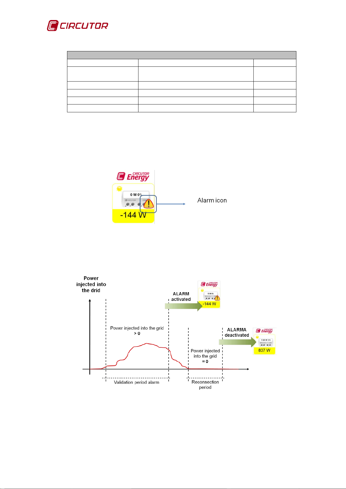
If power is injected into the grid during the period defined by the Stop time
parameter, relay number 4 (NO (terminals 9- 10)) is desactivated (If Stop time is
programmed with the value 0 this function remains deactivated). In addition, an
orange alarm icon appears on the web site, as shown in Figure 7:
Figure 7: Hardware control alarm activated.
When the current injected into the grid disappears, after the Reconnection
time, the alarm status is deactivated.
Figure 8: Inverse current relay reconnection time.
16 Instruction Manual
Page 17
CDP
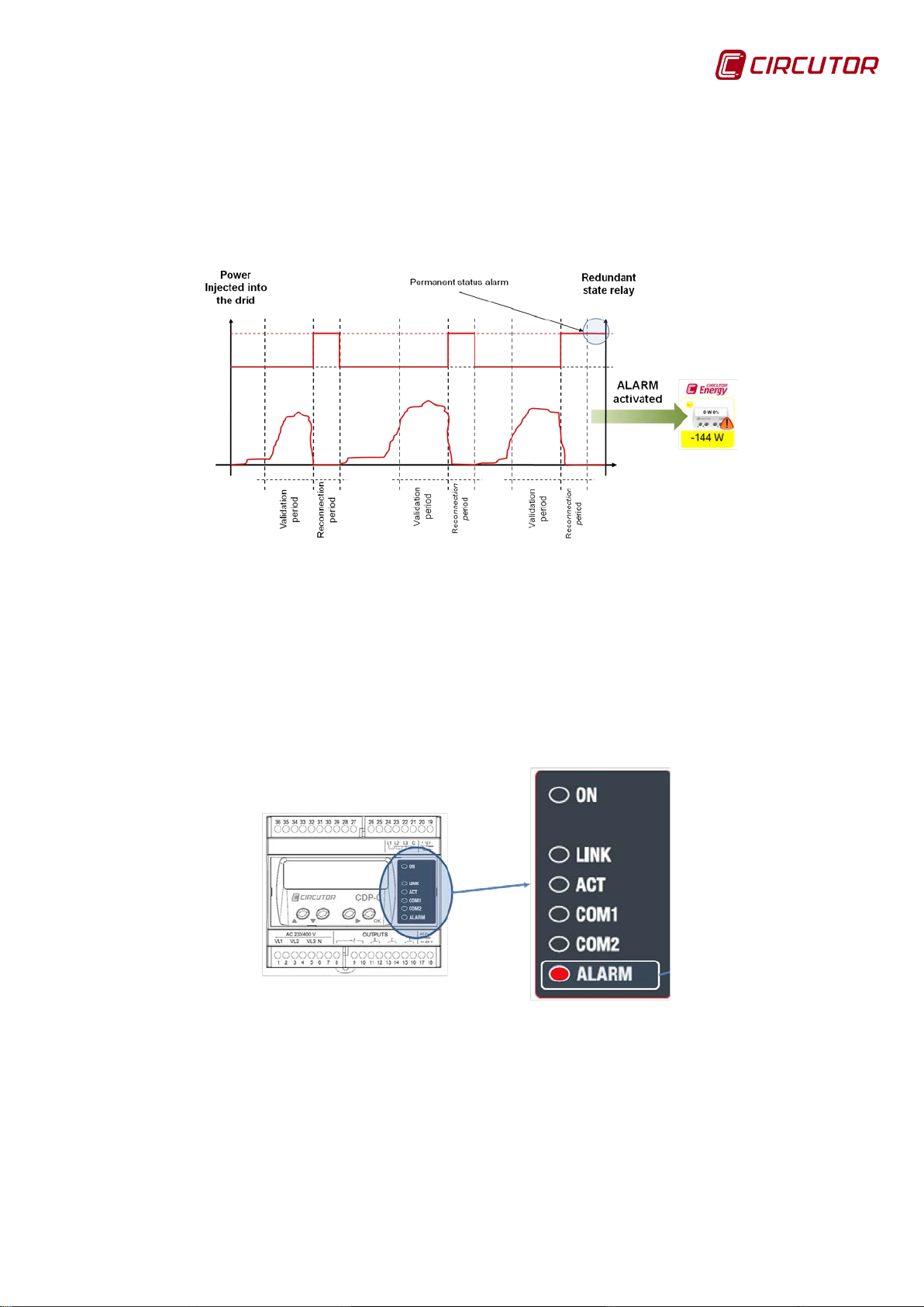
If the maximum number of reconnection attempts defined in the Max
Disconnections parameter is reached within the time defined in the maximum
reconnection period, Disconnect. Timeout parameter, the unit definitively
activates the alarm.
Figure 9: alarm reconnection sequence.
The following indications appear in the CDP when the reconnection sequence
has been completed:
• Alarm LED: The alarm LED is activated in the CDP indicating that power
is being injected into the grid and that the reconnection sequence is
complete.
Figure 10: Inverse current relay alarm.
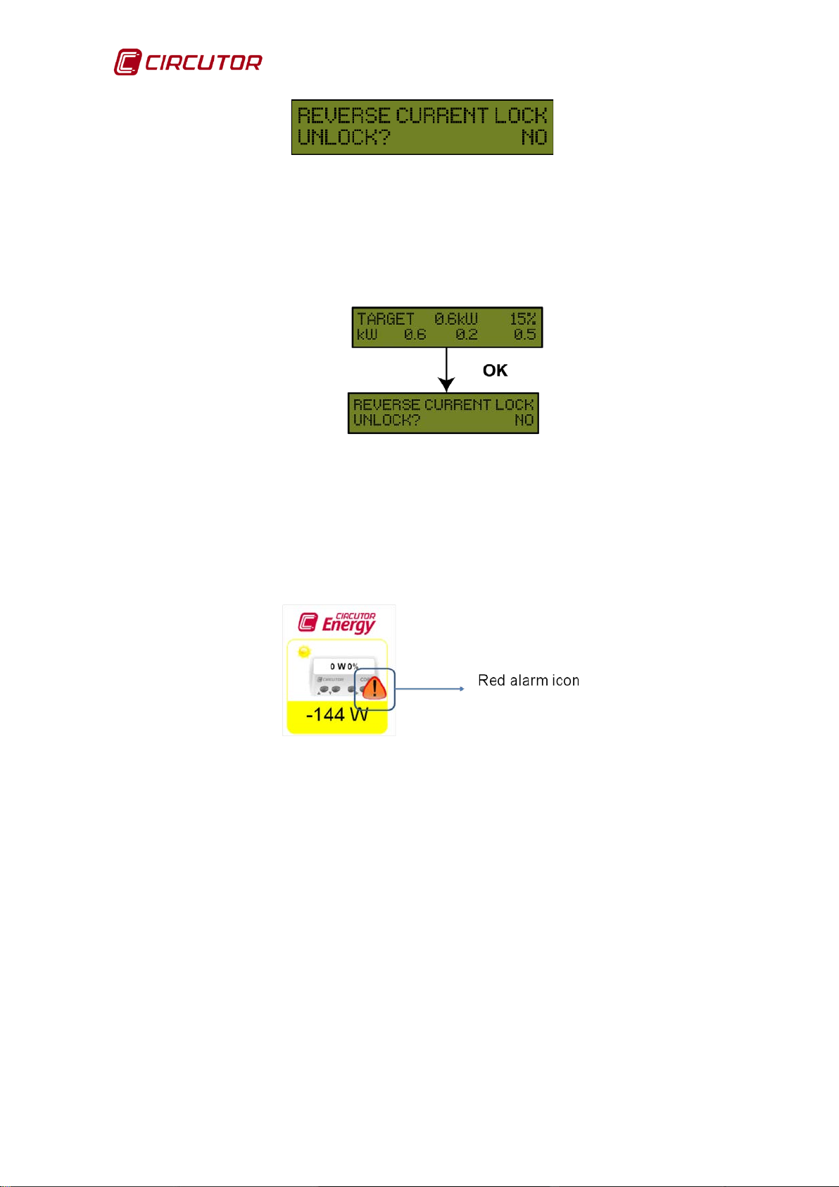
• Unit screen: A screen appears on the CDP indicating that the unit has
activated the inverse current protection relay, and there is an option to
unlock it. The option NO appears on the home screen; this can be
changed with the UP and DOWN keys to YES. Press the OK key to
validate the selected option.
Instruction Manual 17
Page 18
CDP
Figure 11: Inverse current alarm screen.
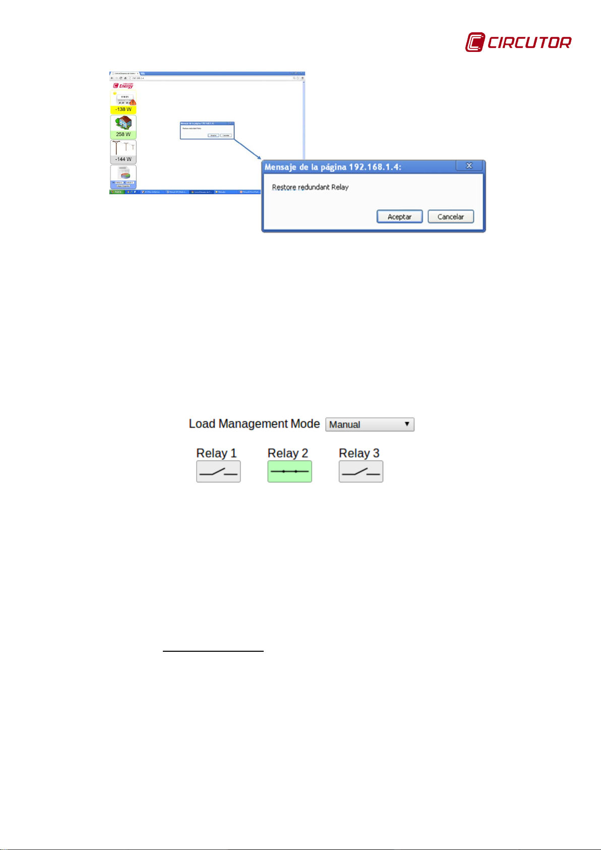
If NO is selected, the alarm remains permanently activated. If the OK key
is pressed on the main screen, the option to deactivate the inverse current
alarm is displayed.
Figure 12: Inverse current alarm display.
If the inverse current alarm is activated, although the unit turns off and on
again, this condition is memorised and the alarm notification will appear
on the screen indicating that it is possible to unlock it.
Web site: The icon is red indicating that the alarm has been activated.
Figure 13: Inverse current relay alarm activated.
If you press above the alarm icon a message will appear asking if you want
to deactivate the grid injection alarm. You can accept or cancel this option as
shown in Figure 14.
18 Instruction Manual
Page 19
CDP
Figure 14: Deactivating the alarm on the web site.
4.1.3. MANAGEMENT OF NON-CRITICAL LOADS (CDP-G Model)
This functionality allows you to add non-critical loads depending on if more
power can be obtained from the inverter. This management can be manual or
dynamic and is carried out through the use of the system's auxiliary relays
(Terminals 11 to 16 of Table 2).
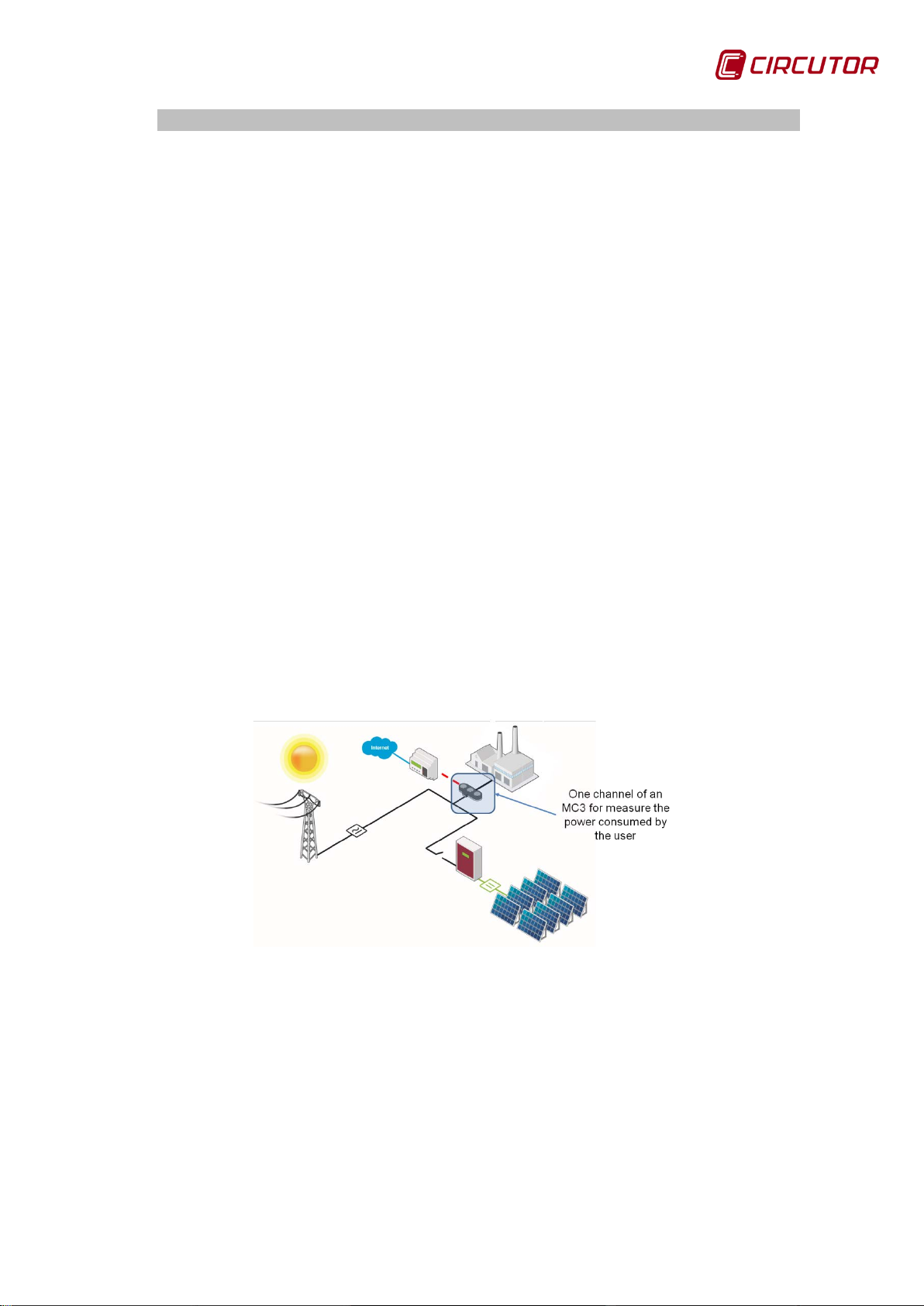
Manual management is performed from the configuration web site, from which
you can view and modify the status of the relays (Figure 15).
Figure 15: Manual management of no n-critical loads from the web site.
When managing dynamic control, the loads are connected based on having
met two conditions:
1.-
Setpoint value ≤ Maximum modulation value.
100 .
Equation 1: Condition 1 for load connection.
Where the Maximum modulation value is the ratio between the power
consumed by the user and the maximum power that can be obtained by the
configured inverters. In other words, the maximum modulation value (%) is:
Instruction Manual 19
Page 20

CDP
Equation 2: Maximum modulation value.
100
2.-
If Injection Margin = 0%
The Grid power < ( 2 x 0.03 x Consumed power)
Equation 3: Condition 2 for load connection (Injection Margin = 0%).
If Injection Margin ≠ 0%
The Grid power < ( 2 x Injection Margin x Consumed power)
Equation 4: Condition 2 for load connection (Injection Margin ≠ 0%).
As soon as conditions 1 and 2 are met, a new load will be added to the system
via the unit's auxiliary relays.
The loads will be disconnected, based on the maximum grid contribution. This
parameter is the ratio between the power supplied to the grid and the sum of the
powers of the loads managed by the system.
Grid
· 100
GC
Equation 5: Maximum grid contribution.
As soon as the value is greater than or equal to the value programmed by the
user, the last relay to be activated will be deactivated.
To ensure correct system stability, a minimum reclosing time (programmable by
the user) must pass between the activation and deactivation of two loads or a
single load.
The order in which loads are activated is another parameter that can be set by
the user. The order may be set as: connection by priority or rotating connection.
Connection by priority: In this case the user sets the order in which
loads are to be activated.
Rotating conne ction: Each connection cycle begins with a different load.
In other words, the first connection cycle begins by connecting load 1,
then 2 and finally 3. The following connection cycle will begin with the load
from relay 2, then 3 and finally 1, and so on and so forth.
The disconnection order for both modes is based on a LIFO system in which the
last load connected to the system will be the first load to be disconnected.
20 Instruction Manual
Page 21
CDP
4.2.- APPLICATIONS
The CDP is the ideal unit for managing photovoltaic installations for selfconsumption with and without grid injection.
Four types of configurations can be distinguished depending on the type of grid
connection:
Basic single-phase connection, in which the CDP only measures the
power consumed by the user.
Single-phase connection with monitoring, the CDP measures the
power consumed by the user, the power generated by the inverter and the
power consumed from the gri d.
Basic three-phase connection, in which the CDP only measures the
power consumed by the user.
Three-phase connection with monitoring, the CDP measures the
power consumed by the user, the power consumed from the grid and
calculates the power generated by the inverter.
The different configurations are described below.
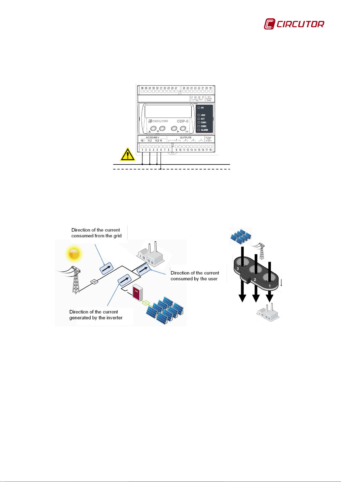
4.2.1. BASIC SINGLE-PHASE CONNECTION
The CDP has a voltage measuring channel (VL1) and a current measuring
channel (IL1) and measures the single-phase power consumed by the user
using a current transformer (an MC1 or channel of an MC3). In this case, since it
does not measure the grid power, it cannot have the grid injection protection
relay function.
Figure 16: Connection diagram for the single-phase measurement system.
4.2.1.1. Voltage connection
For the basic single-phase connection, terminals VL1 and N must be connected
to the single-phase grid (it is recommended that VL2 and VL3 are connected to
N to avoid false measurement s due to noi s e) .
Instruction Manual 21
Page 22

CDP
Figure 17: Voltage connection diagram.
4.2.1.2. Current connection
Only one MC3 channel must be used to measure the current, in this case
number 1. The cable direction is that indicated in Figure 18.
Figure 18: Current connection diagram.
4.2.2. SINGLE-PHASE CONNECTION WITH MONITORING
The CDP has three voltage measuring channels (VL1, VL2 and VL3) and three
current measuring channels (IL1, IL2 and IL3) and uses an MC3 current
transformer to measure the power consumed by the user (VL1, IL1), the power
consumed from the grid (VL2, IL2) and the power generated by the inverter
(VL3, IL3).
Figure 19: Connection diagram for the single-phase measurement system with
monitoring.
22 Instruction Manual
Page 23
CDP
4.2.2.1. Voltage connection
For the single-phase connection with monitoring, the terminals VL1, VL2 and
VL3 must be connected and bridged and connected to the single-phase grid
phase and terminal N to the neutral.
Figure 20: Voltage connection diagram,
4.2.2.2. Current connection
The three channels of the MC3 must be used to measure the current. The cable
direction is that indicated in Figure 21.
Figure 21: Current connection diagram.
4.2.3. BASIC THREE-PHASE CONNECTION
The CDP has three voltage measuring channels (VL1, VL2 and VL3) and three
current measurement channels (IL1, IL2 and IL3), and will measure the threephase power consumed by the user using an MC3 current transformer. In this
case, since it does not measure the grid power, it cannot use the grid injection
protection relay funct ion.
Instruction Manual 23
Page 24

CDP
Figure 22: Connection diagram for the basic three-phase system.
Since this is a three-phase installation connection, each of the measuring
channels VL1, VL2 and VL3 are connected to their corresponding phase of the
three-phase grid.
4.2.4. THREE-PHASE CONNECTION WITH MONITORING
Figure 23 shows a three-phase installation in which the CDP directly measures
the user's consumption, in this case a small-scale industry, by connecting an
MC3 current measurement transformer. The power control uses its RS485
channel to communicate with a CVM type three-phase measuring unit. This unit
is responsible for measuring the power consumed by the grid.
Figure 23: Connection diagram for the three-phase system with monitoring.
Since this is a three-phase installation connection, each of the measuring
channels VL1, VL2 and VL3 are connected to their corresponding phase of the
three-phase grid.
24 Instruction Manual
Page 25
CDP
Loads
4.3.- OPERATING EXAMPLES FOR THE CDP-G MODEL
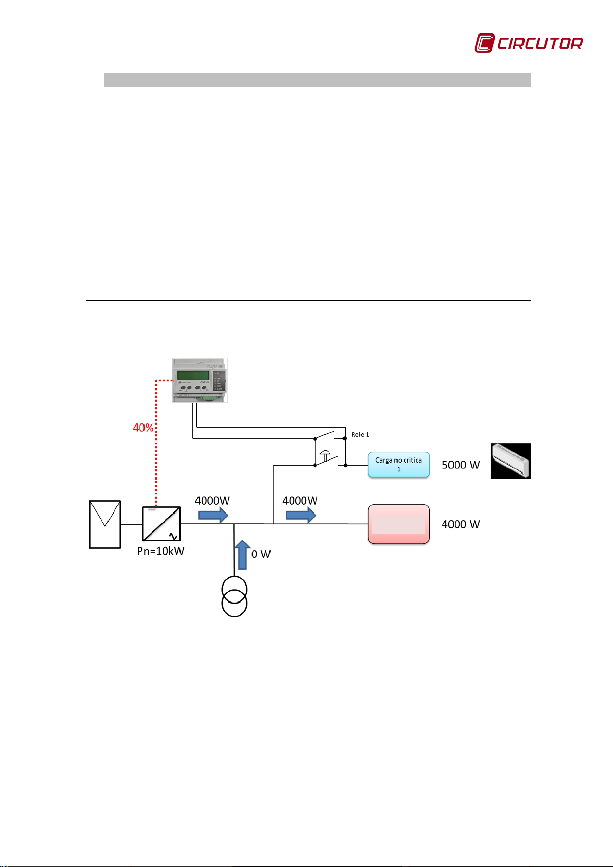
4.3.1. SINGLE-PHASE INSTALLATION WITH 1 LOAD TO BE CONNECTED
We start with a single-phase installation in which we want to use the excess
photovoltaic production to supply 1 non-critical load, such as a heat pump.
• Load 1: 5000 W heat pump
The goal is to activate these loads during times in which there is a production
excess, thus reducing energy costs.
This is the baseline data:
Phase P. Inverter Consumption Setpoint Current production
L1 10000 W 4000 W 40% 4000 W (40% of the nominal)
Figure 24: Single-phase installation with 1 load to connect.
The CDP-G programming is shown in Table 11 :
Instruction Manual 25
Page 26

CDP
VARIABLE
VALUE
Inverter power
10000 W
Number of inverters
1
Phase control
Single-phase
Injection margin
0 %
Load management Mode
Dynamic
Max. modulation value
90 %
Max. grid contribution
20 %
Reconnecting time
5 minutes
Relay 1
Relay 2
Relay 3
Power
5000 W
Power
Power
Min.
time
Min.
time
Min.
time
Table 11: CDP-G programming (Single-phase installation with 1 load to connect).
connection
90 minutes
connection
connection
• Max. modulation value = 90%. This means that as long as the ratio be-
tween Pconsumed/Available PV Power is below 90%, the CDP-G will try to
connect the associated loads.
• Max. grid contribution = 20% This means that as long as the load can op-
erate with less than 20% of the power in the distribution lines, the CDP-G will
keep the loads connected. If the load needs more than 20% of the grid power, the CDP-G will disconnect the load once the Min. disconnection time has
passed.
In this situation, the CDP-G checks its working conditions:
• Condition 1:
100 .
(
100 = 40%) 40% ≤ 90% this condition is met
• Condition 2:
-If Injection Margin = 0% It checks whether:
Pgrid < 2 x (0.03) x Pconsumed
-If Injection Margin ≠ 0% It checks whether:
Pgrid < 2 x Injection Margin x Pconsumed
0 < 2 x 0.03 x 4000 this condition is met
If the 2 conditions are met, the relay closes and connects
the load. (Figure 25)
26 Instruction Manual
Page 27

CDP
Loads
Figure 25: Single-phase installation with 1 load to connect (Load Connected).
In this situation the CDP-G maintains the system without adding or removing any
loads for a time equalling the longer of the configured “Reconnection time” and
“Min. disconnection time” variables, in order to achieve system stability (in this
case 90 minutes).
To check if this load must be disconnected, the CDP-G waits for the amount of
time programmed in the “Min. connection time” variable and then checks if the
following condition is met:
• Disconnection condition:
< .
(
= 60%) 60% ≤ 20%
this condition is NOT met the CDP-G open the relay.
Instruction Manual 27
Page 28
CDP
Loads
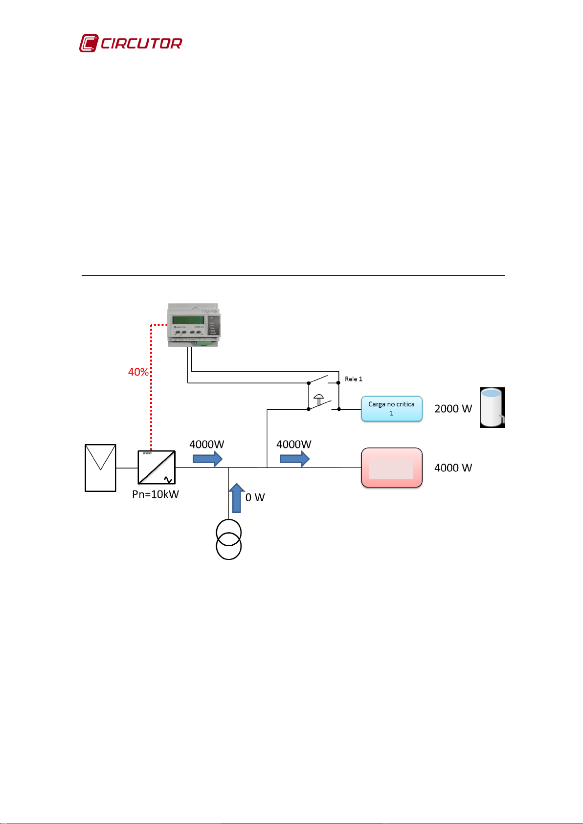
4.3.2. SINGLE-PHASE INSTALLATION WITH 3 LOADS TO BE CONNECTED
We start with a single-phase installation in which we want to use the excess
photovoltaic production to supply 3 non-critical loads:
• Load 1: 2000 W water pump
• Load 2: 2000 W heat pump
• Load 3: 1000 W washing machine
The goal is to activate these loads during times in which there is a production
excess, thus reducing energy costs.
This is the baseline data:
PhaseP. Inverter Consumption Setpoint Current production
L1 10000 W 4000 W 40% 4000 W (40% of the nominal)
Figure 26: Single-phase installation with 3 loads to be connected.
The CDP-G programming is shown in Table 12 :
28 Instruction Manual
Page 29

CDP
VARIABLE
VALUE
Inverter power
10000 W
Number of inverters
1
Phase control
Single-phase
Injection margin
0 %
Load management Mode
Dynamic
Max. modulation value
90 %
Max. grid contribution
50 %
Reconnecting time
5 minutes
Relay 1
Relay 2
Relay 3
Power
2000 W
Power
2000 W
Power
1000 W
Min.
time
2 minutes
Min.
time
2 minutes
Min.
time
90 minutes
Table 12: CDP-G programming (Single-phase installation with 3 loads to connect).
connection
connection
connection
• Max. modulation value = 90%. This means that as long as the ratio be-
tween Pconsumed/Available PV Power is below 90%, the CDP-G will try to
connect the associated loads.
• Max. grid contribution = 50%. This means that as long as the load can op-
erate with less than 50% of the power in the distribution lines, the CDP-G will
keep the loads connected. If it needs more than 50% of the grid power, it will
disconnect the loads connected to the relays.
In this situation, the CDP-G checks its working conditions to connect the first
load:
• Condition 1:
100 .
(
100 = 40%) 40% ≤ 90% this condition is met
• Condition 2:
-If Injection Margin = 0% It checks whether:
Pgrid < 2 x (0.03) x Pconsumed
-If Injection Margin ≠ 0% It checks whether:
Pgrid < 2 x Injection Margin x Pconsumed
0 < 2 x 0.03 x 4000 this condition is met
If the 2 conditions are met, the relay closes and connects
the load. (Figure 27)
Instruction Manual 29
Page 30

CDP
Loads
Figure 27: Single-phase installation with 3 loads to connect (Load 1 Connected).
In this situation the CDP-G maintains the system without adding or removing any
loads for a time equalling the longer of the configured “Reconnection time” and
“Min. disconnection time” variables, in order to achieve system stability (in this
case 5 minutes).
To check if this load must be disconnected, the CDP-G waits for the amount of
time programmed in the “Min. connection time” variable and then checks if the
following condition is met:
• Disconnection condition:
< .
Then, the CDP-G will check whether it can connect the next load. To do so, it
must verify whether the 2 connection conditions are met:
• Condition 1:
(
= 0%) 0% ≤ 50%
this condition is met relay 1 stays connected
(
100 = 60%) 60% ≤ 90% this condition is met
100 .
30 Instruction Manual
Page 31

CDP
Loads
• Condition 2:
-If Injection Margin = 0% It checks whether:
Pgrid < 2 x (0.03) x Pconsumed
-If Injection Margin ≠ 0% It checks whether:
Pgrid < 2 x Injection Margin x Pconsumed
0 < 2 x 0.03 x 6000 this condition is met
If the 2 conditions are met, the relay closes and connects the load.
So, the CDP-G will connect the second load, as shown in Figure 28:
Figure 28: Single-phase installation with 3 loads to connect (Load 1 and 2 Connected).
In this situation the CDP-G maintains the system without adding or removing any
loads for the amount of time configured in the “Reconnection time” variable, in
order to achieve system stability (in this case 5 minutes).
To check if this load must be disconnected, the CDP-G waits for the amount of
time programmed in the “Min. connection time” variable and then checks if the
following condition is met:
Instruction Manual 31
Page 32

CDP
• Disconnection condition:
< .
(
= 0%) 0% ≤ 50%
this condition is met relay 2 stays connected
At this point, the CDP-G will check whether it can connect the third load. To do
so, it must verify whether the connection condition is met:
• Condition 1:
(
100 = 80%) 80% ≤ 90% this condition is met
• Condition 2:
-If Injection Margin = 0% It checks whether:
Pgrid < 2 x (0.03) x Pconsumed
-If Injection Margin ≠ 0% It checks whether:
Pgrid < 2 x Injection Margin x Pconsumed
0 < 2 x 0.03 x 8000 this condition is met
If the 2 conditions are met, the relay closes and connects load number 3.
100 .
(Figure 29)
32 Instruction Manual
Page 33
CDP
Loads
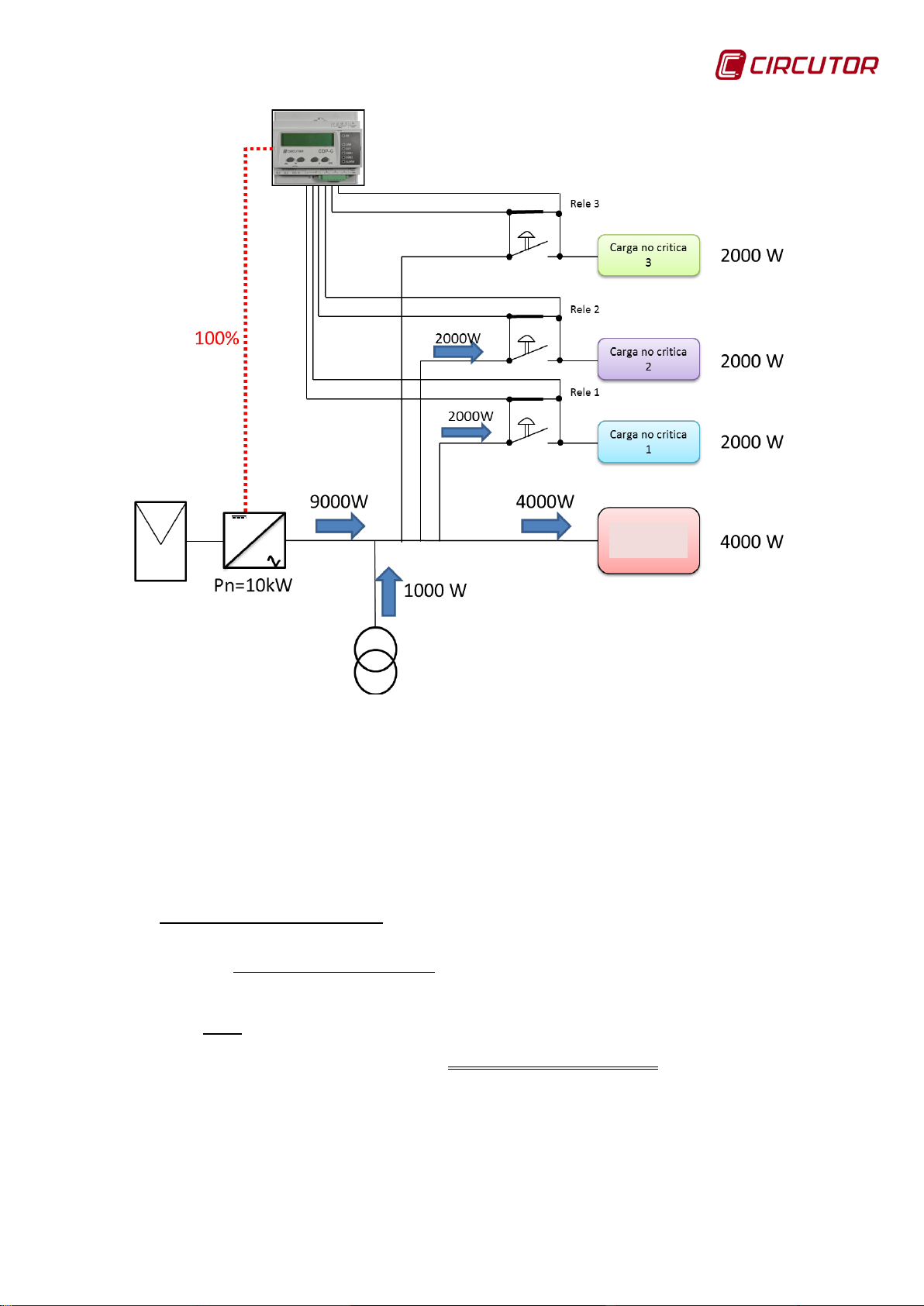
Figure 29: Single-phase installation with 3 loads to connect (Load 1, 2 and 3 Connected).
As shown in Figure 29, we can see that although the inverter is 10 kW the
existing radiation only allows it to produce 9 kW, so to get 10 kW of consumption
it will have to take 1 kW from the grid.
In this situation the CDP-G maintains the system without adding or removing any
loads for the amount of time configured in the “Reconnection time” variable, in
order to achieve system stability (in this case 5 minutes).
• Disconnection condition:
< .
this condition is met relay 3 stays connected
(
= 10%) 10% ≤ 50%
Instruction Manual 33
Page 34

CDP
Reference
name
4.4.- KEY FUNCTIONS
The CDP has four keys so that the user can browse through the different
screens on the unit.
Figure 30: Description of the keys.
Table 13: Description of the key operations.
Format Description FUNCTIONALITY IMPROVEMENTS
Scroll up
Scroll down
Scroll right
OK validation key
Allows you to go back through the
display of the unit's screens
Allows you to go forward through the
display of the unit's screens
Allows you to go forward in the list of
options on the menus.
Allows you to validate the parameter
entries.
DOWN
RIGHT
The reference name will be that used in the document to define the functions of
each key.
The keys must be held down for 1 second.
UP
OK
34 Instruction Manual
Page 35
CDP
Function
Description
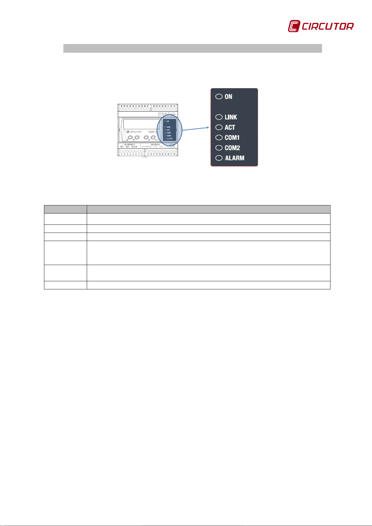
Flashing mode indicates that the unit is ON (flashes at a rate of 1 second).
LINK
Connection to the active Ethernet network (fixed value).
ACT
Communication frames are being sent (flashing)
Indicates the communications status of the R2 channel to which the inverters
inverters it has connected and responding.
Indicates the communications status of the R3 channel through which the
CDP communicates with the auxiliary CVM Mini units (flashing).
ALARM
Indicates the grid injection alarm status. (fixed value)
4.5.- LED INDICA TORS
The CDP has six LEDs so that it is easy for the user to identify the operating
status of the unit.
Figure 31: CDP LED indicators.
Table 14: Description of the LED operation.
ON
COM1
COM2
are connected. In 1 second, the unit flashes as many times as the number of
Instruction Manual 35
Page 36

CDP
4.6.- DISPLAY
The CDP includes a 20-character, two-line display which is used as a user
interface.
If the unit is configured to work in single-phase mode, the default screen is
shown in Figure 32.
The regulation percentage and corresponding power are indicated on the line
above; in the example shown in the figure below, the nominal power of the
inverter is 4.0 kW and the CDP is sending an order to inject 15%, corresponding
to 0.6 kW.
Figure 32: Description of the first line of the standby screen.
If the connection has been performed correctly, the three power values should
appear with a positive sign. If any of the values appear with a negative sign, this
means that the cable of the phase in question has been connected the other way
round and should there fore be tur ne d.
The power consumption for each of the three measuring channels is indicated
on the line below.
Figure 33: Description of the second line of the standby screen.
If the unit is configured to work in three-phase mode, the default screen is
shown in Figure 34.
The same information as the single-phase configuration is shown on the first
line.
The total three-phase power is shown on the second line.
36 Instruction Manual
Page 37

CDP
Figure 34: Home screen for the three-phase configuration.
When you pre ss the RIGHT key the menu is displayed with the following options
(Figure 35):
• Measures: Displays the electrical parameters measured by the unit.
• Network: Configuration of the unit's network.
• System: Displays the unit version and the date and time of configur ation.
Figure 35: Management of the main menus.
Press the UP or DOWN key to browse the options.
Press the RIGHT key to enter any of the two options.
Press the OK key to exit this menu.
Instruction Manual 37
Page 38

CDP
5.- DISPLAY AND CONFIGURATION
5.1. MEASURES MENU
The following screen sequence appears when you select the “Measures” option:
1- If the unit is configured in single-phase, the voltage and current for each
of the phases are displayed on this screen, the resolution is set with one decimal
place:
Figure 36: First screen of the measures menu in single-phase mode.
If the unit is configured in the three-phase, mode, the average of the
voltage and current for each of the three phases is displayed in the first
column, the resolution is set with one decimal place:
Figure 37: First screen of the measures menu in three-phase mode.
2- If the unit is configured in single-phase mode, the inductive reactive
power and voltage and three-phase capacitive power are displayed in the first
column, the resolution is set with one decimal place:
Figure 38: Second screen of the measures menu in single-phase mode.
If the unit is configured in three-phase mode, the inductive reactive
power and three-phase capacitive power are shown in the first column,
the resolution is set with one decimal place:
Figure 39: Second screen of the measures menu in three-phase mode.
Note: A negative sign indicates that the direction of the current is inversed.
3- Consumed active energy:
US corresponds to the user's energy, GR is the energy from the grid and
PV is that from the inverter.
The units are kWh and the resolution is set with one decimal place:
38 Instruction Manual
Page 39

CDP
Figure 40: Third screen on the measures menu.
4- Inductive reactive energy consumed.
US corresponds to the user's energy, GR is the energy from the grid and
PV is that from the inverter.
The units are kVArh and the resolution is set with one deci mal pl ace :
Figure 41: Fourth screen on the measures menu.
5- Capacitive reactive energy consumed.
US corresponds to the user's energy, GR is the energy from the grid and
PV is that from the inverter.
The units are kVA r h and the resolution is set with one decimal place:
Figure 42: Fifth screen on the measures menu.
6- Active energy generated by each of the three phases.
US corresponds to the user's energy, GR is the energy from the grid and
PV is that from the inverter.
The units are kWh and the resolution is set with one decimal place:
Figure 43: Sixth screen on the measures menu.
7- Inductive reactive energy generated.
US corresponds to the user's energy, GR is the energy from the grid and
PV is that from the inverter.
The units are kVArh and the resolution is set with one decimal place:
Figure 44: Seventh screen on the measures menu.
Instruction Manual 39
Page 40

CDP
8- Capacitive reactive energy generated.
US corresponds to the user's energy, GR is the energy from the grid and
PV is that from the inverter.
The units are kVArh and the resolution is set with one decimal place:
Figure 45: Eighth screen on the measures menu.
From the first screen using the UP and DOWN keys the following sequence
continues until the sequence of the rotating menu is complete and you return to
the first screen.
Press the OK key to exit this menu and return to the previous menu.
Figure 46 shows the screen sequence included in the Measures me nu, for the
single-phase and three-phase configuration.
40 Instruction Manual
Page 41

CDP
Figure 46: Measurement display menu
5.2. NETWORK MENU
The CDP unit has self-detecting Ethernet 10/100BaseTX connectivity which
means that, in order to integrate the device into a Local Area Network, it must be
provided with a previous IP addressing configuration.
The user can access the configuration parameters via the display and the
function keys on the front panel of the unit, or through the internal configuration
web site, which is accessible via a conventional Internet browser. (See section
6.1.SETUP WEB SITE)
Instruction Manual 41
Page 42
CDP
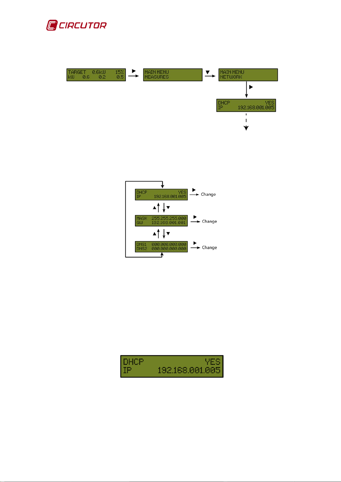
The following sequence must be completed to access the Ethernet channel's
setup menu, Figure 47:
Figure 47: Communications setup sequence.
Figure 48 shows the group of screens included in the setup of the Ethernet
communications channel communications.
Figure 48: Communications pa rameters to be configured on the CDP.
5.2.1. DHCP ASSIGNMENT
After entering the setup menu, the unit displays DHCP (Dynamic Host
Configuration Protocol), and by default shows the YES option. To modify the
option shown on the screen, press the RIGHT key and DHCP will b e displayed
intermittently, if you press the UP or DOWN key the NO option will be displayed.
Do this twice and the unit cyclically displays both options until one of them is
validated with the OK key.
Figure 49: First communications setup screen on the CDP.
42 Instruction Manual
Page 43

CDP
5.2.2. DHCP OPTION: YES
The unit will then display the parameters assigned by the DHCP server. The unit
will display the following fields which cannot be edited.
• IP Configuration
The second line shows the IP address than has been dynamically assigned.
Figure 50: First setup screen if DHCP is YES.
• NetMask and Gateway
The netmask is shown on the first line and the Gateway on the second.
Figure 51: Second setup screen if DHCP is YES.
• Primary DNP and Secondary DNS
The preferred DNS server is shown on the first line and the alternative on the
second.
Figure 52: Third setup screen if DHCP is YES.
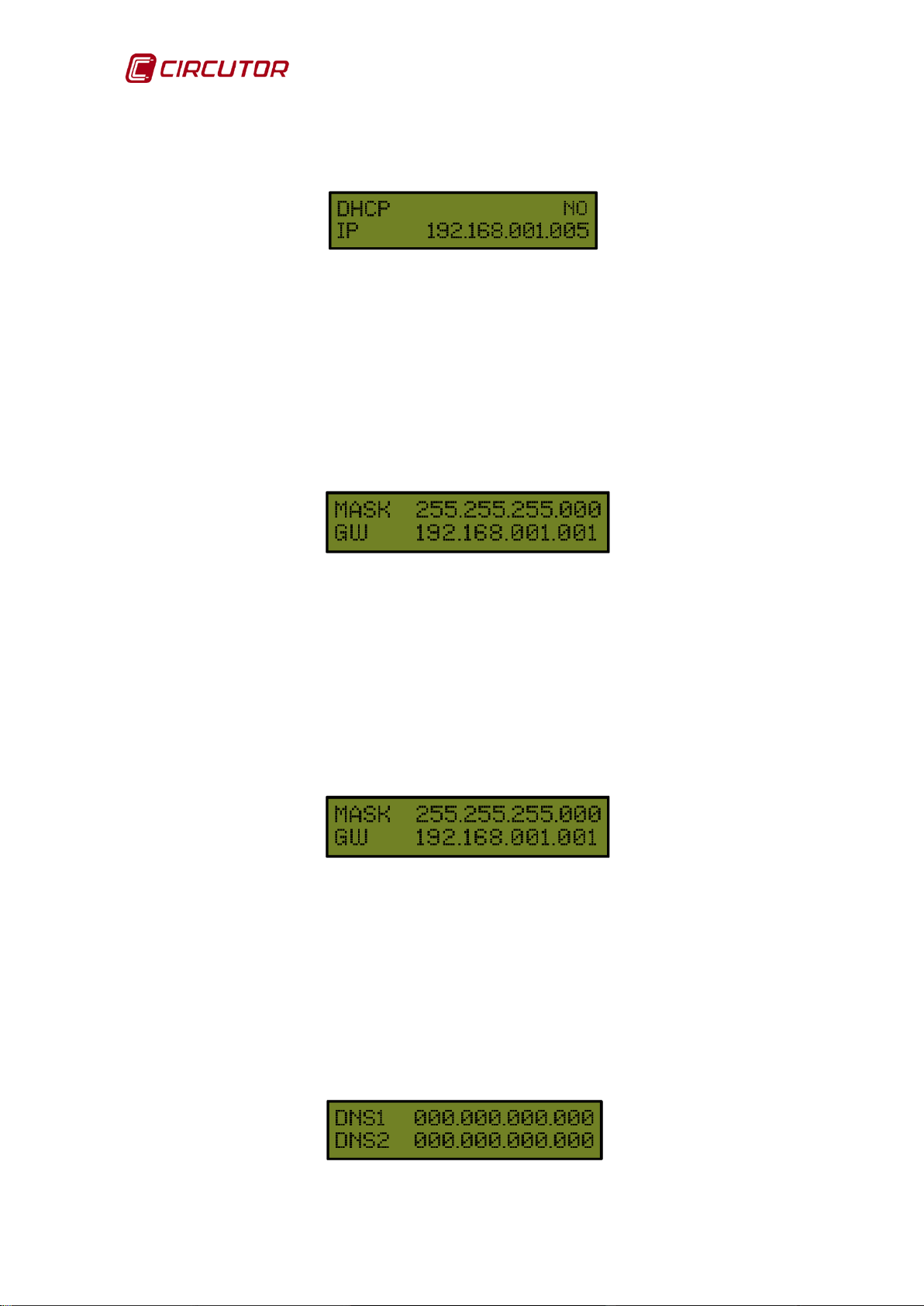
5.2.3. DHCP OPTION: NO
If the DHCP server is not activated, validate the NO option using the UP and
DOWN keys, moving to the next screen.
Figure 53: First setup screen if DHCP is NO.
Instruction Manual 43
Page 44
CDP
• IP
The user configures an IP address for the CDP unit using the setup optio n.
Figure 54: First setup screen if DHCP is NO.
• NetMask
To configure the NetMask, press the Scroll RIGHT key, activating the edit cursor
on the first digit. Press the UP and DOWN keys to establish the parameters of a
000.000.000.000 type numeric data entry. After establishing the parameters,
press the RIGHT key repeatedly until the edit cursor disappears and validate the
data with the OK key, moving to the next line.
Figure 55: Second setup screen if DHCP is NO.
• Gateway
To configure the Gateway, press the Scroll RIGHT key, activating the edit cursor
on the first digit. Press the UP and DOWN keys to establish the parameters of a
000.000.000.000 type numeric data entry. After establishing the parameters,
press the RIGHT key repeatedly until the edit cursor disappears and validate the
data with the OK key, moving to the next screen.
Figure 56: Second setup screen if DHCP is NO.
• Primary DNS
To conf igu re t he Pr imary DNS pre ss t he RIGHT key, activating the edit cursor on
the first digit. Press the UP and DOWN keys to establish the parameters of a
000.000.000.000 type numeric data entry. After establishing the parameters,
press the RIGHT key repeatedly until the edit cursor disappears and validate the
data with the OK key, moving to the next line.
Figure 57: Third setup screen if DHCP is NO.
44 Instruction Manual
Page 45
CDP
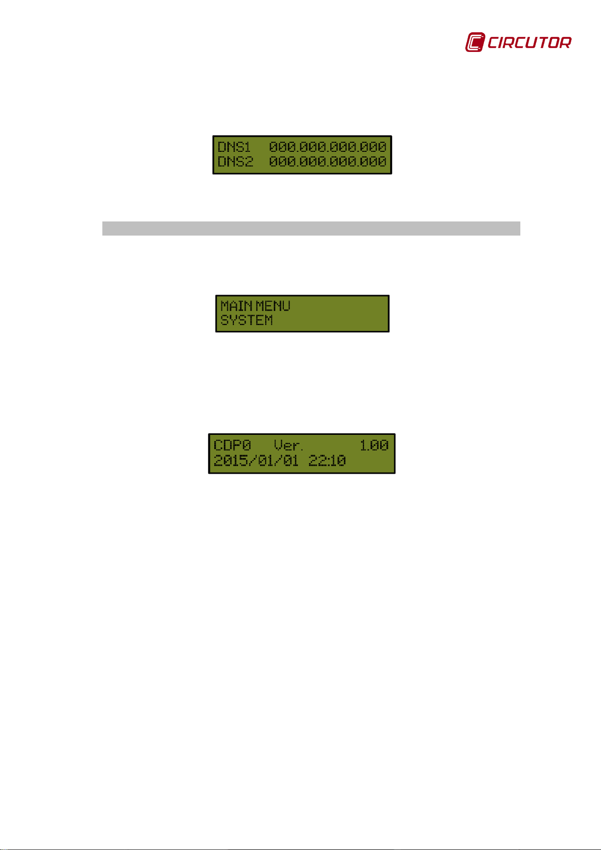
• Secondary DNS
To configure the Secondary DNS server, carry out the same procedure as with
the Primary DNS.
Figure 58: Third setup screen if DHCP is NO.
5.3. SYSTEM MENU
The SYSTEM option appears on the CDP's main menu and displays the
firmware version of the unit, allowing you to adjust the time.
Figure 59: Date and time setup me n u .
The firmware version of the unit is displayed on the first line.
The second line shows the date and time, if you press the RIGHT key the digits
will be displayed intermittently. Using the UP and DOWN, keys you can modify
any date and year value and the changes can be saved by pressing the OK key.
Figure 60: Date and time setup me n u .
Note: If the CDP is used as a data logger, check that the date and time are
correct.
Instruction Manual 45
Page 46
CDP
Default
value
Inverter power
W
1
Number of inverters
-
1
Work mode configuration
-
Single-phase
Activate compensation
-
0
No injection threshold
%
3
Permitted power to be injected
%
0
Activate the management of non-critical loa ds
-
disabled
Maximum modulation value
%
50
Relay connection order
-
Priority
Maximum grid contribution value
%
25
Minimum reconnection time
Minutes
5
Power to be consumed by eac h of the l oads connected
to the relays
Minimum time that the load must stay connected
Minutes
15
Activate reverse current relay
-
1
Grid injection validation time
Seconds
0
Reconnection time
Seconds
0
Maximum number of reconnections
-
0
Reconnection period
Seconds
0
Time between datalogger logs
Minutes
15
Activate external unit to measure the user's current
-
0
Transformation ratio for the current of L1 (Channel for
measuring the user's current in single-phase mode)
Peripheral number address
(External unit activated)
Transformation ratio for th e current of L2 (Channel for
measuring the grid's current in single-phase mode)
Peripheral number address
-
1
Activate external unit to measure the inverter's current
-
0
Transformation ratio for th e current of L3 (Channel for
measuring the inverter's current in single-phase mode)
Peripheral number address (External unit activated)
-
2
Communication speed with the grid ana lyzers.
Bauds
19200
6.- COMMUNICATIONS
The unit has two web sites:
Configuration web site.
Display web site.
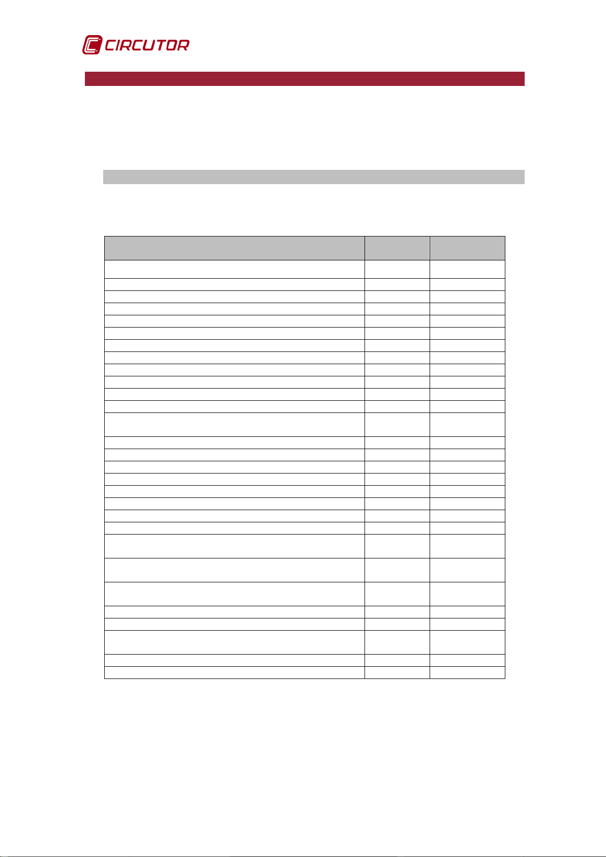
6.1. CONFIGURATION WEB SITE
The CDP can be used to configure the parameters of the Table 15, via Web.
Table 15: Configuration parameters.
Description Units
Inverter type - Fronius
W -
A/250 mA 1
- -
A/250 mA 1
A/250 mA 1
46 Instruction Manual
Page 47
CDP
You can enter the unit web site from any browser using the IP address.
https://xxx.xxx.xxx.xxx/setup/index.html
Where xxx.xxx.xxx.xxx is the IP address assigned by the user.
Note: Use Google Chrome.
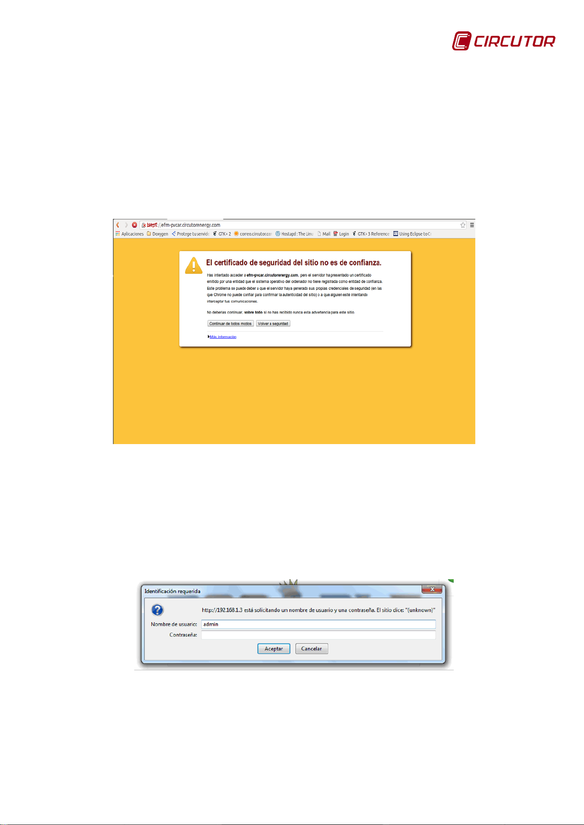
Note: When you access the CDP web site for the first time, you will have to
accept the security certificate so that you can use secure connections.
Figure 61: Acceptance alert for the SSL secure connection certificate.
Access via password
If a password has been parameterised, the unit requests these access
parameters when trying to access via the web site in the following pop-up screen
(username: admin):
Figure 62: Screen for enterin g u sername and password
Instruction Manual 47
Page 48

CDP
6.1.1. CDP Setup
The unit information is displayed in the upper part of the web site, Figure 63.
Figure 63: Setup web site: unit information.
• Firmware upgrade
It is possible to upgrade the firmware of the unit with the Upgrade button. The
upgrade file must be downloaded from the Circutor web site
( www.circutor.es).
When press ing the Upgrade button, the s creen in Figure 64 appears, where
you will need to find the upgrade file that you have downloaded onto the
computer and press the Upgr ade button.
Figure 64: Firmware upgrade screen.
During the upgrade process, you will see the screen in Figure 65.
Figure 65: Screen during the upgrade process.
.
48 Instruction Manual
Page 49

CDP
Note: If the CDP is upgraded with the wrong firmware version for the product,
a version error message will appear on the display as shown in Figure 66.
Figura 66: Version error screen.
• Date
The date on which the web site is updated is displayed in this parameter.
It is also possible to change the date and time of the unit, entering the
required value and pressing the Update button.
• Config File
When pres sing the Download button, the configuration file is downloaded in
.txt format.
• Data Logger
It is possible to reset the historical data stored in the data logger by pressing
the Reset button.
Instruction Manual 49
Page 50

CDP
6.1.2. Power control & Data logger
In this part, Figure 67, five groups of parameters are displayed:
Those related to the model and number of inverters: Inverter.
Those related to inverter control: Control.
Those related to the operation of the reverse current control relay:
Reverse current relay.
Those related to managing non-critical loads: Auxiliary load relays.
That related to the data log generated: Data logger.
Figure 67: Setup web site: Power control & Data logger.
6.1.2.1. Inverter
In this section you can select:
• Inverter type: Inverter model to be used in the installation. All inverters
connected to the CDP must be of the same type.
If you select the option Generic 4 inputs, the parameter Mode appears on the
screen with two possible options (Figure 68):
Discrete: this option allows 4 regulation stages: 0%, 30%, 60% and 100%.
50 Instruction Manual
Page 51

CDP
When the Binary option is activated, relay number 4 stops functioning
as a protection against reverse current and starts functioning like the
rest of the relays.
Binary: this option allows 16 regulation stages between 0% and 100% of the
inverter's nominal power. The relay combinations are done using binary logic.
Figure 68: Setup web site: detail of the inverter section.
If the SMA option is selected, the Inverter X S/N, Figure 69 parameter will
appear on the screen, where you will need to enter the serial numbers of
each of the inverters.
It is important to enter the serial number of each inverter in the phase in
which it was installed, so that the device can detect it.
Figure 69: Setup web site: detail of th e Inverter section (SMA).
• Inverter power: Total power to be controlled by the CDP. (in the event of two
2000 W inverters, enter 4000 W).
The power limit is 1 MW.
• Number of inverters: number of inverters to control.
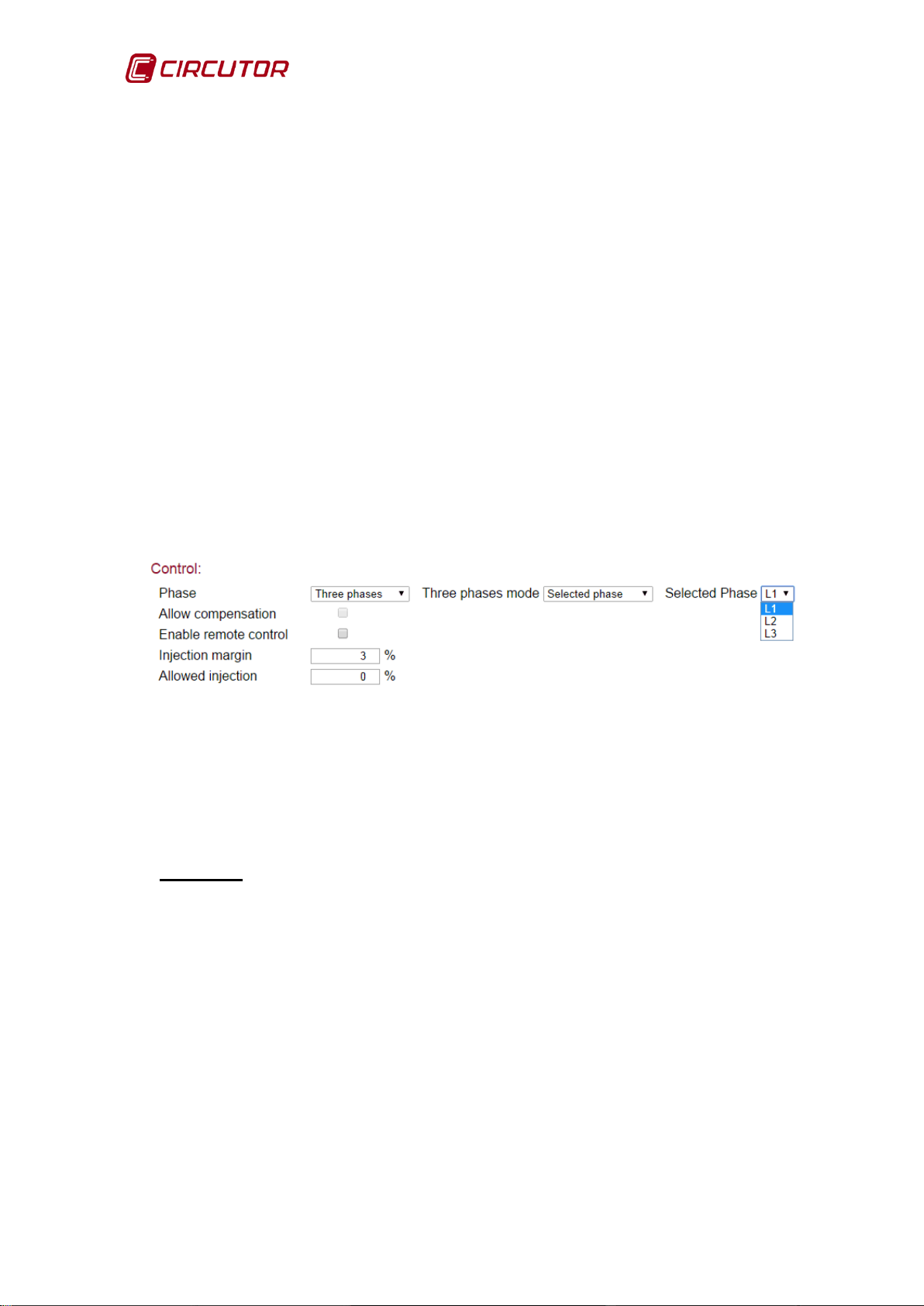
6.1.2.2. Control
Inverter control param eter s :
• Phase: the architecture of the inverter grid connection must be selected. The
available options are:
Single phase: single-phase installation with single-phase inverters.
Three phase: three-phase installation with three-phase inverters.
Three single phases: three-phase installation with three single-phase
inverters .
Instruction Manual 51
Page 52
CDP
If we select the Three phase option the parameter Three phases mode will
appear on the screen, allowing us to select the control mode. The options
are:
Min. power phase, control by minimum power: when this option is selected
the CDP sends a production setpoint based on the phase of the minimum
consumption.
Max. power phase, control by maximum power: the CDP sends a production
setpoint based on the phase of the maximum consumption.
Selected phase, control by set phase: this option allows the user to set a
phase such that the CDP will always send the production setpoint to the
inverter based on that phase's consumption. When this option is selected a
dropdown menu appears on the screen allowing you to select the phase
(Figure 70)
Average power, control by average power: this option takes an average of the
consumption of the three phases and sends a production setpoint to the
inverter with the value of the average power.
Figure 70: Setup web site: detail of the inverter section.
• Allow compensation (from 2 inverters): This function allows you to manage
several inverters independently to obtain the maximum generation fr om each
of them.
Example: For example, an installation with two 5 kW inverters connected to
2 strings of independent panels on a gabled roof in the east-west direction
and consumption of 4 k W.
If in the morning, inverter 1 can generate 5 kW but inverter 2 can only generate 1 kW, because the panels are not receiving sufficient radiation, rather
than requesting 2 kW from each inverter, the CDP will request the maximum
power from the inverter that generates the least (1 kW) and the remainder
will be requested from the inverter which generates more (3 kW), to try to
reach the required consumption.
To do this, it will gradually increase the regulation percentage of both inverters at the same time until both generate a total power equivalent to that required by the load.
Note: In three-phase systems, the connection of a CVM Mini is mandatory to
measure the power consumed/delivered to the mains.
52 Instruction Manual
Page 53

CDP
Digital input
Default value
1
0
2
30
3
60
4
100
• Enable remote control: on activating this option, the options injection mar-
gin and allowed injection are deactivated.
This option facilitates the remote control of the setpoint value, through the
unit's digital inputs.
The value of the digital input selected is a percentage that it added to the
fixed setpoint value.
By default, the value of the digital inputs are:
Table 16: Default values of the digital inputs.
Example: For a consumption of 600 W and a 4kW inverter
Under these conditions the CDP will calculate a setpoi nt of 15%.
No input activated: the CDP maintains the calculated setpoint.
Input 1 activated: the CDP maintains the calculated setpoint.
Input 2 activated: the CDP adds 30% to the calculated setpoint (the new set-
point will be 45%).
Input 3 activated: the CDP adds 60% to the calculated setpoint (the new set-
point will be 75%).
Input 4 activated: the CDP sends the 100% setpoint to the inverter. (100%
will be the maximum setpoint).
If several digital inputs are activated, the CDP will always take the highest as
a reference.
• Injection margin: Minimum contribution from the grid as a percentage of the
consumed power. Default value: 3%.
Example: if consumption is 3 kW, and the injection margin is 10%, the CDP
will try to take 300 W from the grid and will therefore send the inverter a setpoint so that it will provide 2700 W.
• Allowed injection: Percentage of injection in excess of the consumed
power.
This value can be positive or negative with respect to the photovoltaic power.
The negative values are used for hybrid networks, renewable and nonrenewable networks (UPS, generator set, grid, etc.), where it is important that
the non-renewable network is not permanently connecting and disconnecting.
A negative Allowed injection forces the non-renewable energy source to
constantly supply a residual percentage of the consumption.
Example: For example, an installation with one 5 kW inverter and a 100 kW
generator set.
Consumption is 4 kW and one of the loads needs to be permanently supplied.
Instruction Manual 53
Page 54

CDP
In this case, the variable Inverter power will be programmed to 5000 W and
the variable Allowed injection to a value of -1%. Therefore, the generator
set will always be connected, supplying 50 W.
6.1.2.3. Inverse current relay
Parameters for the inverse current control relay (see 4.1.2. OPERATION OF THE
GRID INJECTION PROTECTION RELAY):
• Enable inverse current relay: activates the inverse current relay protection.
If the unit measures a negative power value in the grid, it desactivates the
inverse current relay (relay no. 4, NO terminals 9-10) to disconnect the
inverter.
This relay acts as redundant protection against a possible grid injection.
The relay has 3 terminals and can be NO or NC, depending on how it is
connected.
In three-phase mode it is essential to install a CVM Mini to measure the grid.
• Stop time: time during which the grid injection condition must remain active
before activating the inverse current relay (seconds).
• Reconnection time: time the unit waits before deactivating relay no. 4
(seconds) when it stops measuring the inverse current.
• Max. Disconnections: number of disconnections the CDP can perform via
the inverse current before it is definitively locked.
• Disconnect. Timeout: once the maximum number of reconnections has
been reached, this is the time taken for the unit to secure the inverse current
relay. This value must be equal to or higher than:
Disconnect. Timeout > = ( Stop time+ Reconnection time) x (Max.Disconnections).
6.1.2.4. Auxiliary load relays
(see 4.1.3. MANAGEMENT OF NON-CRITICAL LOADS (CDP-G Model))
• Load Management Mode: allows you to select if you want to manage non-
critical loads:
Disabled : It does not manage non-critical loads.
Manual: It manages non-critical loads manual ly.
Dynamic : It manages non-critical loads dynamically.
If you select the Manual option, the 3 relays appear on the screen (Figure 71):
54 Instruction Manual
Page 55

CDP
Figure 71: Setup web site: Auxiliary load relays (Manual).
You can manually activate each relay by pressing the corresponding button for
each one.
If you select dynamic management of the loads (Figure 72), you have to program
the following parameters:
Figure 72: Setup web site: Auxiliary load relays (Dynamic).
• Max. modulation value: In this section you enter the maximum modulation
value and can add dynamic loads to the system below.
• Connection Order: Select how you are going to connect the relays: By pri-
ority or rotating
• 1st/2nd/3rd Priority: If you have selected priority connection, you will then
select the priority for each of the relays.
• Max. grid contribution: In this section you enter the value for maximum grid
contribution, which is the minimum value for deactivating loads.
• Reconnecting time: Minimum time to allow system stabilisation between:
- the activation of two loads.
- the deactivation of two loads.
- the deactivation of the last load and the activation of a new one.
Instruction Manual 55
Page 56

CDP
• Relay 1, Relay 2, Relay 3: Configuration of the relays.
- Power : Power to be consumed by the load. If it is zero, the load is
considered to be deactivated.
- Min. connection time: Minimum time that a load must stay connected
before it can be deactivated, if required.
6.1.2.5. Data logger
(see 6.2.1. CDP AS A DATA LOGGER)
• Time between logs: time to record logs in the Data Logger: 1, 5, 10, 15
or 60 minutes.
6.1.3. Analy zers setup
It is also possible to configure the communications between the CDP and the
CVM Mini or CVM Net power analyzers (Figure 73) on the web site.
Figure 73: Setup web site: Analyzers setup.
6.1.3.1. Load analyzer
• Enable external analyzer: facilitates the use of an external analyzer rather
than the CDP as a measuring unit.
• Primary current: primary value of the load analyzer of the current
transformer.
• Device number: Peripheral number of the external analyzer.
(Only activated when the “Enable external analyzer” option is activated).
6.1.3.2. Grid analy zer
• Primary current: primary value of the grid analyzer of the current
transformer.
• Device number: peripheral number of the CVM power analyzer installed to
measure the consumption of the grid.
56 Instruction Manual
Page 57

CDP
6.1.3.3. PV analy zer
(1)
• Enable external analyzer: facilitates the use of an external analyzer rather
than the CDP as a measuring unit to produce photovoltaic energy.
(Only in three-phase installations).
• Primary current: primary value of the PV analyzer of the current
transformer.
• Device number: Peripheral number of the external analyzer.
(Only activated when the “Enable external analyzer” option is activated).
(1)
The CDP automatically calculates the values of the photovoltaic production
using the consumption measurements (Load analyzer) and the grid (Grid
analyzer).
Therefore, enabling this option is only of interest in installations which already
have a CVM power analyzer installed, which is not communicating with any
system (software or automaton) and the user wants the CDP to read the values
measured by this analyzer.
6.1.3.4. Communications
This section can be used to configure the transmission speed of the RS-485 bus
(Baudrate).
6.1.4. Network & Security Setup (see 5.2.1. DHCP ASSIGNMENT)
6.1.4.1. Network
To assign the fixed IP address, enter the MAC address shown on the side label
attached to the unit, the format of which is 00:26:45:XX:XX:XX.
Enter the IP address that must be configured in the Address f ield; do the same
with the Netmask a nd the Gateway if necessary.
6.1.4.2. Security
This section allows you to enter or change a password to access the setup
menu. When this password is activated, the web browser will allow access to
monitoring, but the access password will be requested when a user wants to
enter the setup:
Instruction Manual 57
Page 58

CDP
Figure 74: Setup web site: Network & Security Setup.
6.1.5. Save setup, Load default setup and Reset CDP
There are 3 buttons at the bottom of the web sit e, Figure 75.
Figure 75: Setup web site: Save setup, Load default setup, Reset CDP.
58 Instruction Manual
Page 59

CDP
When all the changes have been made, select the SAVE SETUP option at the
bottom of the web site and the configuration will be saved in the CDP.
When selecting this button, the unit loads the default values.
When selecting this button, the CDP is reset.
Instruction Manual 59
Page 60
CDP
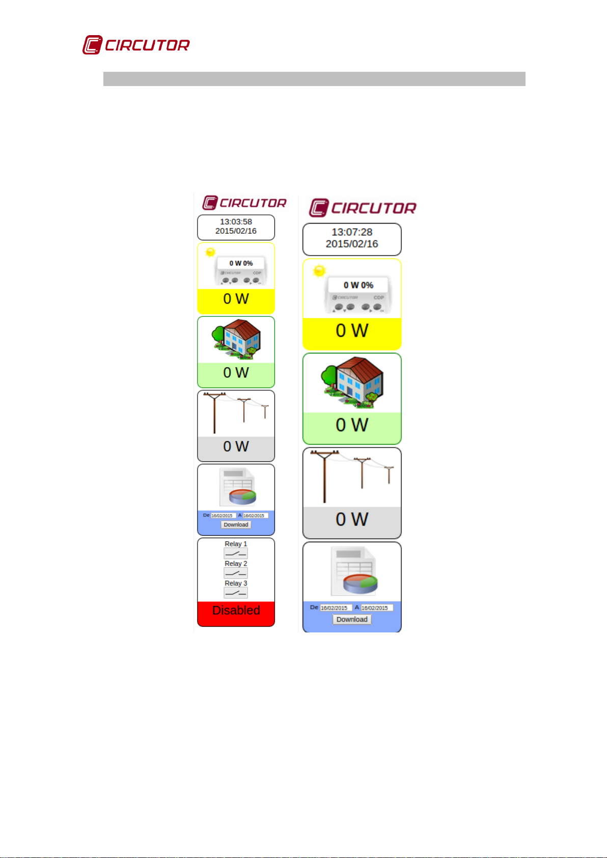
6.2. DISPLAY WEB SITE
The unit has a web site that can display the energy generated, the energy
consumed and the energy injected into the grid. Moreover, in the upper section,
the regulation percentage and the corresponding power with respect to the
inverter nominal power are displayed.
CDP-G CDP-0
Figure 76: Information that appears on the CDP web site.
60 Instruction Manual
Page 61
CDP
6.2.1. CDP AS A DATA LOGGER
This function allows you to install only the CDP in a first phase, without the
inverters and solar panels, so that you can regularly analyse the power
consumed and the energy accumulated, in order to analyse the performance of
the installation and thus design the future self-consumption installation.
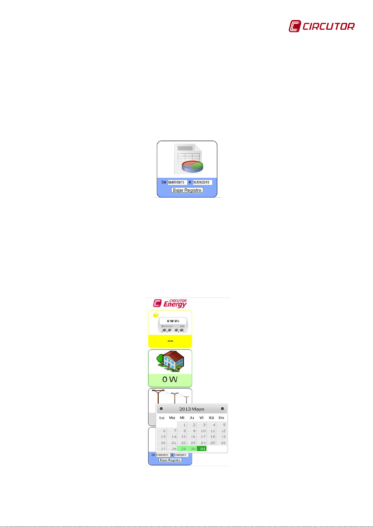
The data is downloaded by accessing the CDP web site. To download the data,
the user must select the days between which they want to download the file with
the data log.
Figure 77: Selecting the download period.
From, Start date for the download period. The download will start at
00:00.
To, End date for the download period. The download will end at 23:59.
On selecting the start or end date a calendar appears which allows you to select
the download period, Figure 78.
The days marked in green are days with a corresponding log.
Figure 78: Introducing the download start and end date.
Instruction Manual 61
Page 62

CDP
Once the start and end date are selected, press the “Download log” key and a
file with the name cdp.csv will be downloaded to the path configured in the web
browser.
The file is downloaded in CSV format and can be opened in Microsoft Excel.
CSV files ( comma-separated values) are a simple file format to represent data
in the form of a table, in which the columns are separated by commas (or a
semicolon in countries which use the comma as the decimal separator: Spain,
France, Italy, etc.) and rows are separated by line feeds.
The file size is 100 MBytes allowing users to save approximately 5200 days in
total. The memory is of the rotating type; when it is full the oldest value is
replaced with the newest one. The size of each log is approximately 200 bytes.
If the time is changed and delayed, the existing log is opened as well as the new
one.
The downloaded file is given the name cdp.csv. If another file is downloaded to
a directory which already contains a file, a new file is generated with the name
cdp (1).csv. The number in brackets increases with the number of successive
downloads in the same directory.
Figure 79: Example of download directory for CDP files.
The files are saved in the download directory selected in the browser.
Figure 80 shows the steps to be performed to configure the download in the
GOOGLE CHROME browser:
1. Select the browser customise icon.
2. Once the setup menu is open, select the "Settings" option.
3. In the setup menu, under the "show advanced settings" option, you can
select the folder in which you would like downloaded files to be saved.
62 Instruction Manual
Page 63

CDP
Figure 80: Selecting the download directory.
Figure 81: Selecting the download directory in Google Chrome.
The CDP can act as a Data Logger and record the electrical parameters that it
measures every 1, 5, 10 or 15 minutes.
If the CDP is configured to work in three-phase mode and the information from
the external CVM Minis is not available, “nan” appears in the corresponding
column.
Instruction Manual 63
Page 64
CDP
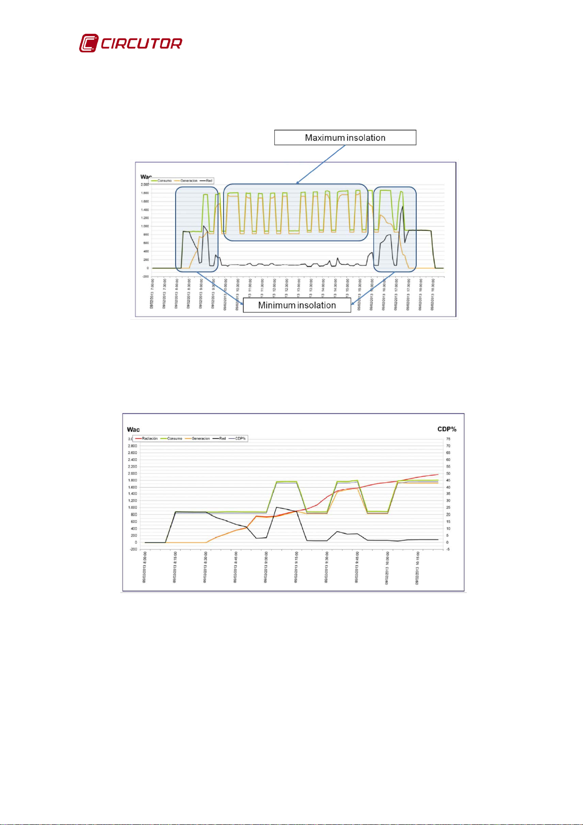
Figure 82 shows that during periods in which insolation is minimum, the user's
consumption is taken from the grid, however, it is the inverter that supplies
energy during periods with maximum insolation.
Figure 82: Graph showing the operation of the CDP based on insolation.
Figure 83 shows the above in more detail: as insolation increases (the red
curve), grid consumption (black line) decreases and the energy generated by the
inverter increases.
Figure 83: Detail of the CDP operation.
When the CDP is configured to work in three-phase mode and there is a
problem with the external CVM Minis or these have not been connected, dashes
appear in the corresponding power indication on the web site.
64 Instruction Manual
Page 65

CDP
Column
Name
(2)
Units
Resolution
Description
DD/MM/YY
HH:MM
Photovoltaic power
produced in L1
Photovoltaic power
produced in L2
Photovoltaic power
produced in L3
Power consumed by
phase 1 load
Power consumed by
phase 2 load
Power consumed by
phase 3 load
GRID
W L1
GRID
W L2
GRID
W L3
Figure 84: In the three-phase configuration there is no communication with the external
CVM Min i
The following table shows the fields recorded in the CDP file.
Table 17: Description of the columns in the CDP file.
1 Date and time
2
3
4
5
6
PV W L1
PV W L2
PV W L3
LOAD W L1
LOAD W L2
W 0.1 W
W 0.1 W
W 0.1 W
W 0.1 W
W 0.1 W
Minute Log date
7
8
9
10
Instruction Manual 65
LOAD W L3
CONSUMPTION
CONSUMPTION
CONSUMPTION
W 0.1 W
W 0.1 W
W 0.1 W
W 0.1 W
Power consumed by
the phase 1 grid.
Power consumed by
the phase 2 grid.
Power consumed by
the phase 3 grid.
Page 66

CDP
Column
Name
(2)
Units
Resolution
Description
GRID INJECTION
W L1
Power injected into
the phase 1 grid.
GRID INJECTION
W L2
Power injected into
the phase 2 grid.
Power injected into
the phase 3 grid.
Regulation
phase 1 inverter
Regulation
phase 2 inverter
Regulation
phase 3 inverter
Energy generated by
the inverter
Energy consumed by
the load
GRID
Wh
Wh
Energy injected into
the grid
Status of relay 1 for
loads
Status of relay 2 for
loads
Status of relay 3 for
loads
11
12
13
14
15
16
17
18
19
GRID INJECTION
W L3
PERCENT L1
PERCENT L2
PERCENT L3
PV Wh
LOAD Wh
CONSUMPTION
W 0.1 W
W 0.1 W
W 0.1 W
% 1%
% 1%
% 1%
Wh 1 Wh
Wh 1 Wh
Wh 1 Wh
percentage of the
nominal power of the
percentage of the
nominal power of the
percentage of the
nominal power of the
Energy consumed by
the grid
20
21
22
23
GRID INJECTION
R1 STATUS
R2 STATUS
R3 STATUS
Wh 1 Wh
Dis : Disabled
M0: Manual mode,relay deactivated.
M1: Manual mode, relay activated.
D0:Dynamic mode,relay deactivated.
D1: Dynamic mode, relay activated.
(2)
The sign criteria in the Data Logger file:
Positive power = consumption
Negative power = generation
managing non-critical
managing non-critical
managing non-critical
66 Instruction Manual
Page 67

CDP
AC power supply
Rated voltage
110…264 V
Frequency
50 … 60 Hz
Consumption
6 VA …10 VA
Installation category
CAT III 300 V
DC Power supply
Rated voltage
12 V
Consumption
4 W
Installation category
CAT III 300 V
Voltage measurement circuit
Voltage measurement margin
10…300 V
Frequency measurement margin
50 … 60 Hz
Input impedance
400 kΩ
Minimum measurement voltage (Vstart)
10 V
Installation category
CAT III 300 V
Current measurement circuit
Nominal current (In)
… / 250 mA
Overcurrent
105% In
Maximum current, impulse < 1s
According to the current sensor
Minimum measurement current (Istart)
10 mA
Installation category
CAT III 300 V
Measurement accuracy
Voltage measurement
0.5%
Current measurement
0.5%
Power measurement
0.5%
Energy measurement
1%
Relay outputs
Quantity
4
Maximum voltage, open contacts
250 V
Maximum current
6 A
Maximum switching power
1500 W
Electrical life
60x103 cycles
Mechanical working life
10x106 cycles
Digital inputs
Quantity
4
Type
Potential-free contact
Insulation
Optoisolated
Communications
User interface
Ethernet
Communications with the inverter
Field bus
RS-232/RS-485/RS-422
Depending on the inverter
(See application notes)
Stop bits
1
Parity
no parity
Communications with other units
Field bus
RS-485
Communications protocol
Modbus
Baud rate
4800-9600-19200-38400
Stop bits
1
Parity
no parity
7.- TECHNICAL FEATURES
Baud rate
Instruction Manual 67
Page 68
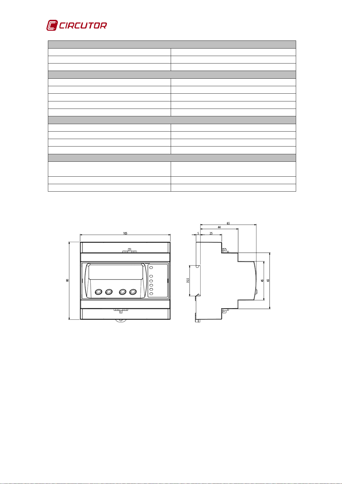
CDP
User interface
Display
Alphanumeric LCD
Keys
4 keys
LED
6 LEDs
Environmental features
Operating temperature
-25 … +70ºC
Storage temperature
-40 … +85 ºC
Relative humidity (without condensation)
95%
Maximum altitude
2,000 m
Protection degree
IP51
Mechanical features
Dimensions
105 x 90 x 70 mm
Weight
250 g
Enclosure
UL94 - V0 self-extinguishing plastic
Fixing
DIN rail
Standards
Safety of electrical measuring and control
units
Electromagnetic c ompat ibility
IEC 61000-6-2:2005
Electromagnetic c ompat ibility
IEC 61000-6-4:2011
IEC 61010-1:2010
Figure 85: CDP dimensions.
68 Instruction Manual
Page 69

CDP
• No returns will be accepted and no unit will be repaired or replaced if it is
not accompanied by a report indicating the defect detected or the reason
The guarantee will be void if the unit has been improperly used or the
ion and maintenance instructions listed in this manual
have not been followed. "Improper usage" is defined as any operating or
tal features of this
8.- MAINTENANCE AND TECHNICAL SERVICE
In the case of any query in relation to unit operation or malfunc tion, please contact the
CIRCUTOR, SA
Technical Assistance Service.
Technical Assistance Service
Vial Sant Jordi, s/n 08232 - Viladecavalls (Barcelona)
Tel.: 902 449 459 (Spain) / +34 937 452 900 (outside of Spain)
email: sat@circutor.es
9.- GUARANTEE
CIRCUTOR guarantees its products against any manufacturing defect for two
years after the delivery of the unit.
CIRCUTOR will repair or replace any defective factory product returned during
the guarantee period.
for th e return.
•
storage, installat
storage condition contrary to the national electrical code or that surpasses the limits indicated in the technical and environmen
manual.
CIRCUTOR
•
other parts of the installation, nor will it cover any possible sanctions derived from a possible failure, improper installation or "improper usage" of
the unit. Consequently, this guarantee does not apply to failures occurring in the following cases:
- Overvoltages and/or electrical disturbances in the supply;
- Water, if the product does not have the appropriate IP classification;
- Poor ventilation and/or excessive temperatures;
- Improper installation and/or lack of maintenance;
- Buyer repairs or modifications without the manufacturer's authorisation.
accepts no liability due to the possible damage to the unit or
Instruction Manual 69
Page 70
CDP
10.- CE CERTIFICATE
70 Instruction Manual
Page 71

CDP
Address
Phase 1
Phase 2
Phase 3
Three-phase
Active power of the grid
(4)
64-65
66-67
68-69
6A-6B
kW
Active power measured in
the load
Active photovoltaic power
74-75
76-77
78-79
7A-7B
kW
Address
Phase 1
Phase 2
Phase 3
Global
Regulation percentage
7D
7E
7F
7C
%
Active three-phase power measured in the load
80-81
kW·h
Active three-phase energy consumed from the grid
82-83
kW·h
Three-phase active photovoltaic energy consumed
84-85
kW·h
Active three-phase energy injected into the grid
86-87
kW·h
Address
Channel 1
Channel 2
Channel 3
CDP measurement current
88
89
8A
A
Voltage measured in the CDP
(7)
8B
8C
8D
V
Parameters measured in
the load
Address
Phase 1
Phase 2
Phase 3
Three-phase
Power Factor (PF)
(5)
8E-8F
90-91
92-93
94-95
-
Voltage THD
(7)
98-99
9A-9B
9C-9D
-
%
Current THD
(7)
9E-9F
A0-A1
A2-A3
-
%
Reactive power
(6)
A4-A5
A6-A7
A8-A9
-
kvar
Apparent power
(6)
AA-AB
AC-AD
AE-AF
-
kVA
Parameters measured in the load
(3)
Address
Units
Three-phase inductive reactive power
(6)
B0-B1
kvarL
Three-phase capacitive reactive power
(6)
B2-B3
kvarC
Three-phase apparent power
(6)
B4-B5
kVA
Frequency
(7)
96-97
Hz
L1-L2 voltage
(7)
B6-B7
V
L2-L3 voltage
(7)
B8-B9
V
L3-L1 voltage
(7)
BA-BB
V
Impor ted three-phase inductive energy
(6)
BC-BF
kvarLh
Impor ted three-phase capacitive energy
(6)
C0-C3
kvarCh
Impor ted three-phase apparent energy
(6)
C4-C7
kVAh
Exported three-phase inductive energy
(6)
C8-CB
kvarLh
Exported three-phase capacitive energy
(6)
CC-CF
kvarCh
Exported three-phase apparent energy
(6)
D0-D3
kVAh
APPENDIX A: MODBUS MAP
Note: All Modbus map addresses are shown in hex adec imal format.
Parameter
(3)
These parameters only accept the read function.
(4)
The sign indicates if it is consumed or generated.
(5)
Number of decimal places: 3
(3)(5)
6C-6D 6E-6F 70-71 72-73 kW
Parameter
Parameter
(3)
(3)(6)
Address Units
Units
Units
(6)
Number of decimal places: 3
Parameter
(7)
(3)
Number of decimal places: 1
(3)
Units
Units
Instruction Manual 71
Page 72
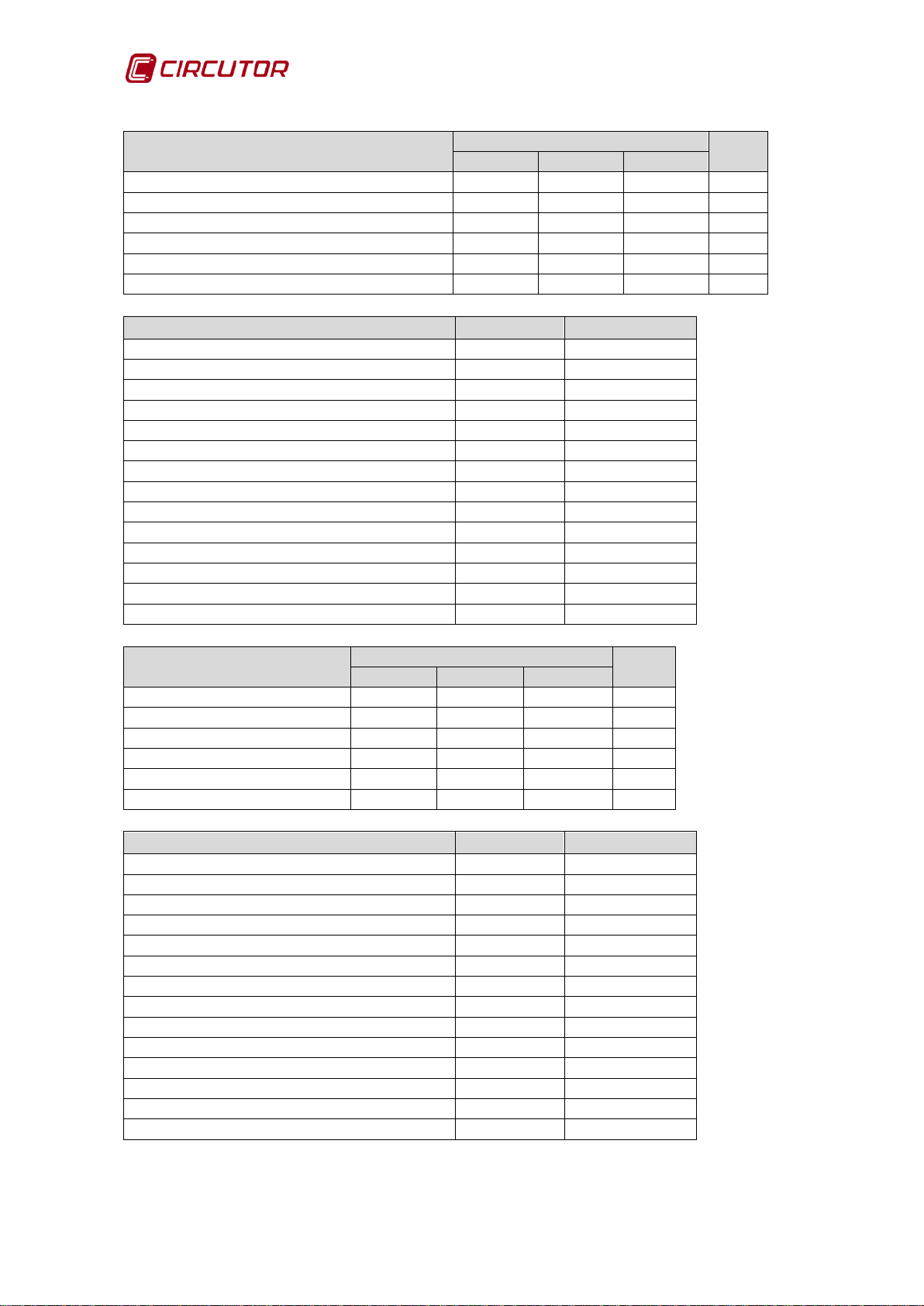
CDP
Address
Units
Phase 1
Phase 2
Phase 3
Voltage
(7)
12C-12D
134-135
13C-13D
V
Current
(7)
12E-12F
136-137
13E-13F
A
Reactive power
(6)
130-131
138-139
140-141
kvar
Power factor
(6)
132-133
13A-13B
142-143
-
Voltage THD
(7)
154-155
156-157
158-159
%
Current THD
(7)
15A-15B
15C-15D
15E-15F
%
Parameters measured in the network
(3)
Address
Units
Three-phase inductive reactive power
(6)
144-145
kvarL
Three-phase capacitive reactive power
(6)
146-147
kvarC
Apparent power
(6)
148-149
kVA
Three-phase power factor
(6)
14A-14B
-
Frequency
(7)
14C-14D
Hz
L1-L2 voltage
(7)
14E-14F
V
L2-L3 voltage
(7)
150-151
V
L3-L1 voltage
(7)
152-153
V
Impor ted three-phase inductive energy
(6)
160-163
kvarLh
Impor ted three-phase capacitive energy
(6)
164-167
kvarCh
Impor ted three-phase apparent energy
(6)
168-16B
kVAh
Exported three-phase inductive energy
(6)
16C-16F
kvarLh
Exported three-phase capacitive energy
(6)
170-173
kvarCh
Exported three-phase apparent energy
(6)
174-177
kVAh
Address
Phase 1
Phase 2
Phase 3
Voltage
(7)
190-191
198-199
1A0-1A1
V
Current
(7)
192-193
19A-19B
1A2-1A3
A
Reactive power
(6)
194-195
19C-19D
1A4-1A5
kvar
Power factor
(6)
196-197
19E-19F
1A6-1A7
-
Voltage THD
(7)
1B8-1B9
1BA-1BB
1BC-1BD
%
Current THD
(7)
1BE-1BF
1C0-1C1
1C2-1C3
%
Photovoltaic parameters
(3)
Address
Units
Three-phase inductive reactive power
(6)
1A8-1A9
kvarL
Three-phase capacitive reactive power
(6)
1AA-1AB
kvarC
Apparent power
(6)
1AC-1AD
kVA
Power factor
(6)
1AE-1AF
Frequency
(7)
1B0-1B1
Hz
L1-L2 voltage
(7)
1B2-1B3
V
L2-L3 voltage
(7)
1B4-1B5
V
L3-L1 voltage
(7)
1B6-1B7
V
Imported three-phase inductive energy
(6)
1C4-1C7
kvarLh
Impor ted three-phase capacitive energy
(6)
1C8-1CB
kvarCh
Impor ted three-phase apparent energy
(6)
1CC-1CF
kVAh
Exported three-phase inductive energy
(6)
1D0-1D3
kvarLh
Exported three-phase capacitive energy
(6)
1D4-1D7
kvarCh
Exported three-phase apparent energy
(6)
1D8-1DA
kVAh
Parameters measured in the network
(3)
Photovoltaic parameters
(3)
Units
72 Instruction Manual
Page 73

CDP
Version
2AF8
Parameter
Address
Status of relays 1, 2 and 3
BB8
Parameter
Address
(10)
Valid data margin
Relay 1
Bit 0
0: relay deactivated 1: relay activated
Relay 2
Bit 1
0: relay deactivated 1: relay activated
Relay 3
Bit 2
0: relay deactivated 1: relay activated
Status of relay 4
(reverse current relay)
0: relay disabled
1: relay activated
Parameter
(11)
Address
Injection Margin
E8
Parameter
Address
Activates remote control
E6
Allowed injection
E7
Parameter
(8)
These parameters only accept the read function.
(8)
Address
This parameter lets you read and modify the status of the relays
(9)
The status of the relays can only be modified when non-critical load management is in
manual mode.
(10)
Higher bits (bit 3, 4, etc.) must be 0 in the write function.
(9)
:
Parameter Address Valid data margin
1
(11)
To save in the memory the change in this parameter through Modbus, you
need to restart the unit.
Instruction Manual 73
Page 74

CIRCUTOR, SA
www.circutor.es central@circutor.es
Vial Sant Jordi, s/n
08232 -Viladecavalls (Barcelona)
Tel.: (+34) 93 745 29 00 - Fax: (+34) 93 745 29 14
 Loading...