

Page 1

REFERENCE MANUAL
9500PPC
MOBILE COMPUTER
DOC Version 2.02
Page 2

Copyright © 2007 CIPHERLAB CO., LTD.
All rights reserved
The software contains proprietary information of CIPHERLAB CO., LTD.; it is provided under a
license agreement containing restrictions on use and disclosure and is also protected by copyright
law. Reverse engineering of the software is prohibited.
Due to continued product development this information may change without notice. The
information and intellectual property contained herein is confidential between CIPHERLAB and the
client and remains the exclusive property of CIPHERLAB CO., LTD. If you find any problems in the
documentation, please report them to us in writing. CIPHERLAB does not warrant that this
document is error-free.
No part of this publication may be reproduced, stored in a retrieval system, or transmitted in any
form or by any means, electronic, mechanical, photocopying, recording or otherwise without the
prior written permission of CIPHERLAB CO., LTD.
For product consultancy and technical support, please contact your local sales representative. Also,
you may visit our web site for more information.
The CipherLab logo is a registered trademark of CIPHERLAB CO., LTD.
Microsoft, Windows, and the Windows logo are registered trademarks of Microsoft Corporation in
the United States and/or other countries.
Bluetooth is a trademark of Bluetooth SIG, Inc., U.S.A.
Other product names mentioned in this manual may be trademarks or registered trademarks of their
respective companies and are hereby acknowledged.
The editorial use of these names is for identification as well as to the benefit of the owners, with no
intention of infringement.
CIPHERLAB CO., LTD.
Website:
http://www.cipherlab.com
Page 3

IMPORTANT NOTICES
FOR USA
This equipment has been tested and found to comply with the limits for a Class B digital device,
pursuant to Part 15 of the FCC Rules. These limits are designed to provide reasonable protection
against harmful interference in a residential installation. This equipment generates, uses and can
radiate radio frequency energy and, if not installed and used in accordance with the instructions, may
cause harmful interference to radio communications. However, there is no guarantee that
interference will not occur in a particular installation. If this equipment does cause harmful
interference to radio or television reception, which can be determined by turning the equipment off
and on, the user is encouraged to try to correct the interference by one or more of the following
measures:
Reorient or relocate the receiving antenna.
Increase the separation between the equipment and receiver.
Connect the equipment into an outlet on a circuit different from that to which the receiver is
connected.
Consult the dealer or an experienced radio/TV technician for help.
This device complies with Part 15 of the FCC Rules. Operation is subject to the following two
conditions: (1) This device may not cause harmful interference, and (2) this device must accept any
interference received, including interference that may cause undesired operation.
FOR CANADA
This digital apparatus does not exceed the Class B limits for radio noise emissions from digital
apparatus as set out in the interference-causing equipment standard entitled "Digital Apparatus,"
ICES-003 of Industry Canada.
This device complies with Part 15 of the FCC Rules. Operation is subject to the following two
conditions: (1) This device may not cause harmful interference, and (2) this device must accept any
interference received, including interference that may cause undesired operation.
Cet appareil numerique respecte les limites de bruits radioelectriques applicables aux appareils
numeriques de Classe B prescrites dans la norme sur le material brouilleur: "Appareils Numeriques,"
NMB-003 edictee par l'Industrie.
FOR HAND-HELD PRODUCT WITH RF FUNCTIONS
This equipment complies with FCC radiation exposure limits set forth for an uncontrolled
environment. This equipment should be installed and operated with minimum distance 20cm
between the radiator & your body. It only operated in hand-held used. If you only transfer data to
Host by WLAN/Bluetooth, please keep the minimum distance 20cm between machine & your body.
Page 4

FOR PRODUCT WITH LASER
Per FDA and IEC standards, the scan engines described in this manual are not given a laser
classification. However, the following precautions should be observed:
CAUTION
This laser component emits FDA / IEC Class 2 laser light at the exit port. Do not stare
into beam.
SAFETY PRECAUTIONS
RISK OF EXPLOSION IF BATTERY IS REPLACED BY AN INCORRECT TYPE.
DISPOSE OF USED BATTERIES ACCORDING TO THE INSTRUCTIONS.
The use of any batteries or charging devices, which are not originally sold or manufactured by
CipherLab, will void your warranty and may cause damage to human body or the product itself.
DO NOT disassemble, incinerate or short circuit the battery.
DO NOT expose the scanner or the battery to any flammable sources.
For green-environment issue, it's important that batteries should be recycled in a proper way.
Under no circumstances, internal components are self-serviceable.
The charging and communication cradle uses an AC power adaptor. A socket outlet shall be
installed near the equipment and shall be easily accessible. Make sure there is stable power
supply for the mobile computer or its peripherals to operate properly.
CARE & MAINTENANCE
This mobile computer is intended for industrial use. The mobile computer is rated IP 64,
however, it may do damage to the mobile computer when being exposed to extreme
temperatures or soaked wet.
When the body of the mobile computer gets dirty, use a clean and wet cloth to wipe off the
dust. DO NOT use/mix any bleach or cleaner. Always keep the LCD dry.
For a liquid crystal display (LCD) or touch screen, use a clean, non-abrasive, lint-free cloth to
wipe dust off the screen. DO NOT use any pointed or sharp object to move against the surface.
If you want to put away the mobile computer for a period of time, download the collected data
to a host computer, and then take out the battery pack. Store the mobile computer and battery
pack separately.
When the mobile computer resumes its work, the main and backup batteries will take a certain
time to become fully charged.
If you shall find the mobile computer malfunctioning, write down the specific scenario and
consult your local sales representative.
Page 5

RELEASE NOTES
VERSION DATE NOTES
2.02 Nov. 22, 2007
2.01 Oct. 03, 2007 Minor changes
2.00 July 10, 2007 New Word template applied
Modified: section 4.4 – UI of ReaderCfg.exe changed
Modified: Appendix II~IV – default values updated
1.08 Feb. 26, 2007
1.07 Oct. 27, 2006
1.06 Sep. 27, 2006
Modified: sections 5.1.2~4 –
Windows Message & Event
Modified: section 1.5.9 List by standards for RFID tags
Modified: section 1.5.4, 1.5.5, and 1.5.7 regarding combination keys
with [Func]
General tab > Data Output >
Modified: section 1.5.9 add Symbologies Enabled
1.05 July 27, 2006
New: section 2.4 CF/SD Card illustrating installation procedure
Corrected: section 1.3.9 Reader – lParam instead of IParam
1.04 June 22, 2006
1.03 June 16, 2006
Modified: section 1.3.9 Reader – RFID
Modified: section 1.3.1 Battery
Modified: section 2.1 Main & Backup Batteries
Modified: Specifications re. Backup Battery
1.02 June 06, 2006
Modified: section 1.3.9 Reader
Modified: section 5.1 ReaderConfig
1.01 May 23, 2006 Company name changed to CIPHERLAB CO., LTD. since April 2006
Modified: section 1.2.3 Dimensions & Specifications
Modified: sections 1.3.4 & 1.3.5 – usage of [Func]
1.00 Mar. 22, 2006 Initial release
Page 6

Page 7

CONTENTS
IMPORTANT NOTICES ...................................................................................................................... - 3 -
For USA .......................................................................................................................................... - 3 -
For Canada .................................................................................................................................... - 3 -
For Hand-held Product with RF Functions ................................................................................... - 3 -
For Product with Laser .................................................................................................................. - 4 -
Safety Precautions ........................................................................................................................ - 4 -
Care & Maintenance ..................................................................................................................... - 4 -
RELEASE NOTES.............................................................................................................................. - 5 -
INTRODUCTION.................................................................................................................................... 1
Getting Familiarized with 9500PPC ................................................................................................. 2
Installing the Hand Strap............................................................................................................. 3
Installing the Pistol Grip............................................................................................................... 4
Dimensions........................................................................................................................................ 5
Features............................................................................................................................................. 5
Inside the Package............................................................................................................................ 6
Accessories........................................................................................................................................ 6
USING THE 9500PPC MOBILE COMPUTER......................................................................................... 7
1.1 Battery ......................................................................................................................................... 7
1.1.1 Installing the Battery.......................................................................................................... 7
1.1.2 Charging the Battery .......................................................................................................... 9
1.1.3 Understanding the Battery Icons....................................................................................... 9
1.1.4 Power Management........................................................................................................... 9
1.2 Memory .....................................................................................................................................10
1.2.1 Caution of Data Loss........................................................................................................11
1.2.2 Checking the Storage Space ...........................................................................................11
1.2.3 Inserting the SD or CF Card .............................................................................................12
1.3 Keypad ......................................................................................................................................13
1.3.1 Using the Keypad ............................................................................................................. 13
1.3.2 Alpha Key.......................................................................................................................... 14
1.3.3 Function Key..................................................................................................................... 14
1.3.4 Task Key ...........................................................................................................................15
1.4 Touch Screen ............................................................................................................................16
1.4.1 Adjusting the Backlight ....................................................................................................16
1.4.2 Re-calibrating the Screen ................................................................................................17
1.5 Notifications.............................................................................................................................. 17
1.5.1 Status LED ........................................................................................................................ 17
1.5.2 Audio ................................................................................................................................. 18
1.5.3 Vibrator .............................................................................................................................18
1.6 Data Capture............................................................................................................................. 18
1.7 Communications....................................................................................................................... 18
Page 8

9500PPC Mobile Computer Reference Manual
1.7.1 Using the Cradle...............................................................................................................
18
1.7.2 Using Wireless Networks ................................................................................................. 19
LEARNING POCKET PC BASICS .........................................................................................................21
2.1 Getting Started..........................................................................................................................21
2.1.1 Today Screen.................................................................................................................... 22
2.1.2 Navigation Bar.................................................................................................................. 23
2.1.3 Taskbar ............................................................................................................................. 24
2.1.4 Input Methods .................................................................................................................. 25
2.2 Finding out the Capabilities of Your Mobile Computer...........................................................26
2.3 Using ActiveSync.......................................................................................................................27
2.3.1 Synchronization with Your Computer..............................................................................28
2.3.2 Add/Remove Programs....................................................................................................28
2.3.3 Backup/Restore ...............................................................................................................29
2.4 Managing Programs .................................................................................................................30
2.4.1 Quick Launch a Program .................................................................................................30
2.4.2 Create a Folder................................................................................................................. 33
2.4.3 Locate a File .....................................................................................................................33
2.4.4 Switch among Programs.................................................................................................. 35
2.4.5 Close or Exit a Program.................................................................................................... 35
2.5 System Reset ............................................................................................................................36
2.5.1 Software Reset (Warm Reboot)....................................................................................... 36
2.5.2 Hardware Reset (Cold Reboot)........................................................................................36
PERSONALIZING THE 9500PPC MOBILE COMPUTER ......................................................................37
3.1 Changing Personal Settings..................................................................................................... 37
3.2 Changing System Settings .......................................................................................................38
3.3 Changing Connection Settings................................................................................................. 40
USING APPLICATIONS........................................................................................................................41
4.1 Wireless Power Manager .........................................................................................................41
4.2.1 Connectivity Status ..........................................................................................................42
4.2.2 Flight Mode.......................................................................................................................43
4.2 Bluetooth Manager...................................................................................................................44
4.2.1 Bluetooth Profiles Supported .......................................................................................... 44
4.2.2 Starting Bluetooth Services............................................................................................. 46
4.2.3 Discovering Bluetooth Devices........................................................................................ 47
4.2.4 Bluetooth ActiveSync .......................................................................................................50
4.2.5 PIM Item Transfer.............................................................................................................54
4.3 Wi-Fi Utility................................................................................................................................. 57
4.3.1 Starting Wi-Fi Networking ................................................................................................57
4.3.2 Monitoring Wireless Network Status ..............................................................................59
4.3.3 Performing a Site Survey ................................................................................................. 60
4.3.4 Configuring Roaming & Power-Saving ............................................................................60
4.3.5 Information Required for Reporting a Problem.............................................................. 61
4.4 Reader Configuration Utility .....................................................................................................62
4.4.1 Checking the Reader Status............................................................................................ 62
4.4.2 RFID Reader Settings....................................................................................................... 63
4.4.3 Data Output ...................................................................................................................... 64
4.4.4 Beeper / Vibrator .............................................................................................................65
Page 9

9500PPC Mobile Computer Reference Manual
4.4.5 Symbology Settings..........................................................................................................
66
4.5 Backup Utility ............................................................................................................................ 67
4.5.1 Backing up Files ...............................................................................................................67
4.5.2 Using Backups for Restore .............................................................................................. 68
4.6 Terminal Service Client ............................................................................................................68
SPECIFICATIONS................................................................................................................................ 69
Platform, Processor & Memory.......................................................................................................69
Communications & Data Capture ..................................................................................................69
Electrical Characteristics ................................................................................................................ 69
Physical Characteristics.................................................................................................................. 70
Environmental Characteristics .......................................................................................................70
Programming Support..................................................................................................................... 71
Accessories......................................................................................................................................71
SCAN ENGINE SETTINGS................................................................................................................... 73
Symbologies Supported ..................................................................................................................73
RFID Tags Supported ......................................................................................................................75
CCD/LASER SCAN ENGINE................................................................................................................77
Reader Settings Table..................................................................................................................... 77
Symbology Settings Table...............................................................................................................78
LR/ELR LASER SCAN ENGINE ...........................................................................................................83
Reader Settings Table..................................................................................................................... 83
Symbology Settings Table...............................................................................................................84
2D SCAN ENGINE...............................................................................................................................89
Reader Settings Table..................................................................................................................... 89
Symbology Settings Table...............................................................................................................90
Page 10

Page 11

INTRODUCTION
The 9500PPC Mobile Computer is the first in the line of CipherLab's Windows Mobile-based
products that runs Windows Mobile 2003; it integrates built-in wireless modules for Bluetooth and
802.11b technologies, as well as powerful utilities for data collection, processing, and transmission. Its
large color transflective TFT display guarantees ease in reading in all lighting conditions.
The 9500PPC Series is robust in construction to meet industry grade requirements, and has been
found durable and resistant to shock, water, and dust. It is specifically designed for all-day, everyday
use as well as for data-intensive applications in harsh environments.
This manual serves to guide you through how to install, configure, and operate the mobile computer.
The Care & Maintenance section is specifically prepared for those who are in charge of taking care of
the mobile computer.
We recommend you to keep one copy of the manual at hand for quick reference or maintenance
purposes. To avoid any improper disposal or operation, please read the manual thoroughly before
use.
Thank you for choosing CipherLab products!
1
Page 12
9500PPC Mobile Computer Reference Manual
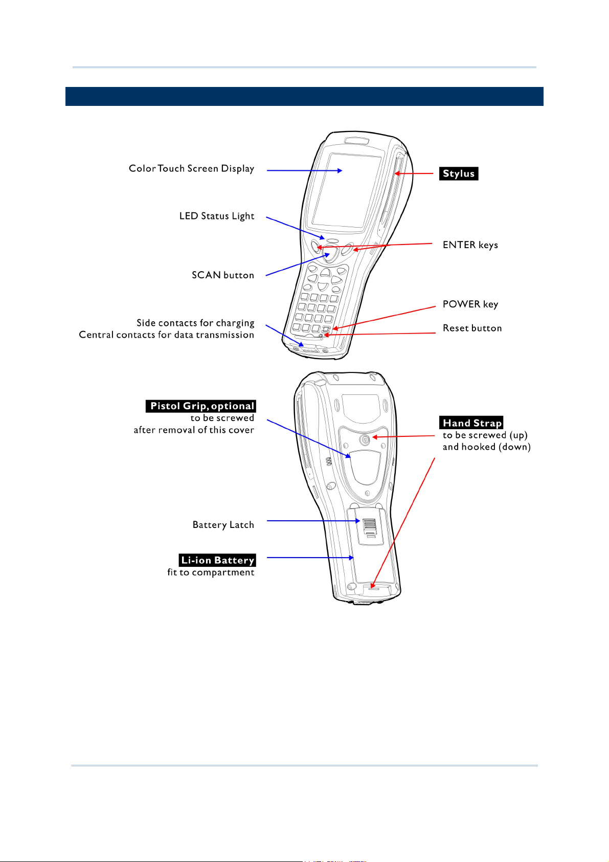
GETTING FAMILIARIZED WITH 9500PPC
Figure 1: Front / Back View
2
Page 13

Introduction
INSTALLING THE HAND STRAP
The hand strap is ideal for one-handed operation, which requires safe and convenient hold of the
mobile computer. Always make sure the hand strap is well hooked and screwed to the back of the
mobile computer. When the hand strap is desired, install it to the mobile computer by following
these steps:
1) Place the mobile computer face down on a flat and clean surface.
2) Screw one end of the hand strap to the shield-like cover on the back of the mobile computer.
3) Insert and hook the other end of the hand strap to the bottom of the mobile computer.
4) Make sure the hand strap is securely attached to the mobile computer.
5) Adjust the length of the hand strap to suit your handbreadth.
Figure 2: Installing the
Hand Strap
3
Page 14
9500PPC Mobile Computer Reference Manual
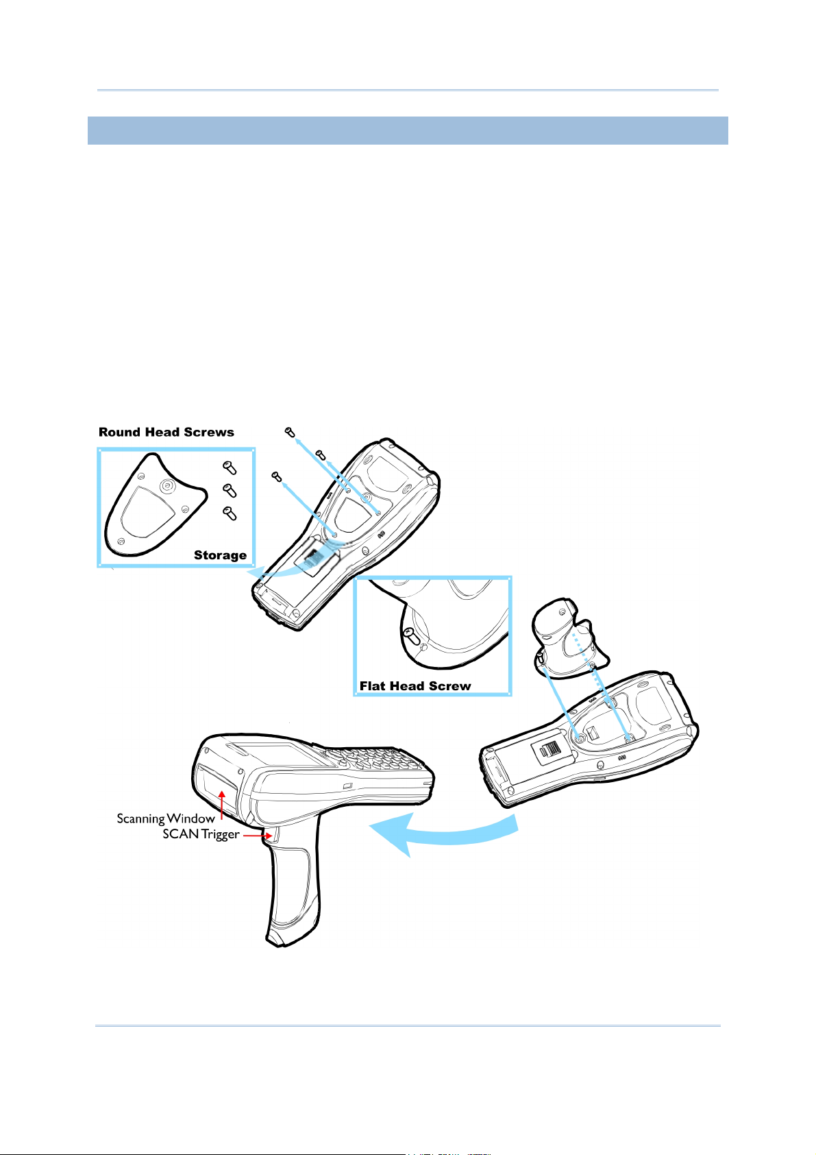
INSTALLING THE PISTOL GRIP
This contoured pistol grip enables intuitive trigger-and-scan operation, which is very helpful in scan
intensive applications. When a pistol grip is necessary, install it to the mobile computer by following
these steps:
1) Place the mobile computer face down on a flat and clean surface.
2) Remove the shield-like cover on the back of the mobile computer by unscrewing.
If the hand strap is installed, remove it first. Keep the cover and screws for future use when the
pistol grip is not desired.
3) Connect the power connector from the pistol grip to the receptacle on the mobile computer.
4) Screw the pistol grip to the shield-like cover.
5) Make sure all screws are tightened up.
6) Turn on the mobile computer and test the trigger.
Figure 3: Installing the
Pistol Grip
4
Page 15
Introduction
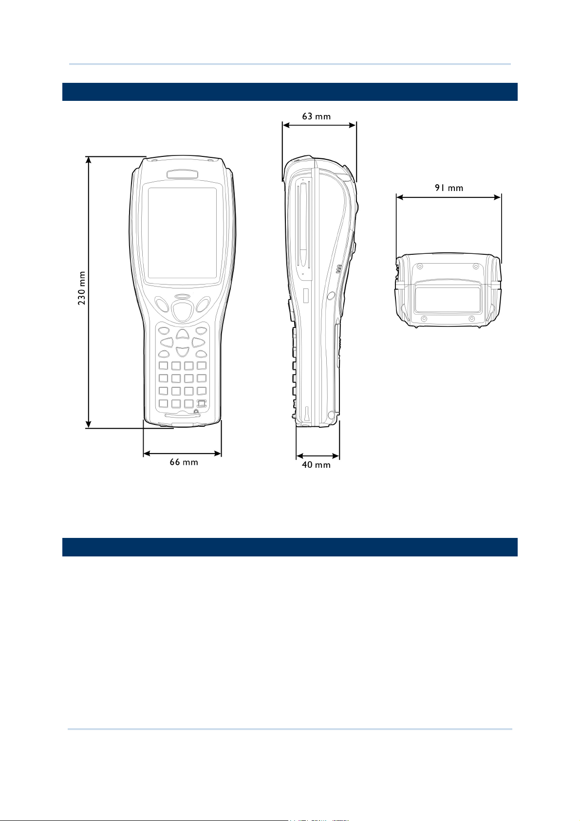
DIMENSIONS
Figure 4: Dimensions
FEATURES
Ergonomic design - ruggedized yet streamlined, with hand strap for secure hold.
Built tough to survive drop test and sealed against moisture/dust to industrial standard IP 64.
Microsoft Windows Mobile 2003 Second Edition operating system, 400 MHz Intel PXA255
processor
128 MB non-volatile NAND flash memory to store OS and software programs
(part of the free space is used as a storage card called DiskOnChip)
64 MB SDRAM to store and run programs, as well as store program data
5
Page 16

9500PPC Mobile Computer Reference Manual
Expansion slots for memory card and peripherals - One for CompactFlash (CF) Type II and the
other for Secure Digital (SD)
Dual mode support - One scan engine (integrated barcode scanner/imager) plus one RFID reader
Combo wireless solution - connectivity includes Bluetooth and 802.11b.
A 3.5" color transflective TFT display delivers excellent visibility in all lighting conditions.
Programmable feedback includes speaker and vibrator.
Built-in power tools include Reader Configuration Utility, Bluetooth Manager, etc.
Terminal Emulation client for VT100/220 and IBM 5250 enables a quick link to any backend
database.
Application Generator (AG*.exe for desktop PC) enables easy customization of data collection
applications.
Programming support includes Reader DLL and System API.
Accessories and peripherals include pistol grip, international AC charging cradle, etc.
INSIDE THE PACKAGE
The following items are included in the package. Save the box and packaging material for future use in
case you need to store or ship the mobile computer.
9500PPC Mobile Computer
Rechargeable Li-ion battery pack
Stylus
Hand Strap
Software & Manual CD
Note: For battery charging, you will need to purchase a charging cradle separately.
ACCESSORIES
Rich choices of optional accessories are available for you to enhance the total performance of the
mobile computer.
Pistol Grip (detachable)
Belt Holster
Protective Cover
Memory Card, SD or CF card
Spare rechargeable Li-ion battery
4-slot Battery Charger
Charging & Communication Cradle
6
Page 17

USING THE 9500PPC MOBILE COMPUTER
This chapter explains the features and usage of the 9500PPC Mobile Computer.
IN THIS CHAPTER
1.1 Battery ................................................................................................................7
1.2 Memory ........................................................................................................... 10
1.3 Keypad ............................................................................................................. 13
1.4 Touch Screen ................................................................................................. 16
1.5 Notifications ................................................................................................... 17
1.6 Data Capture.................................................................................................. 18
1.7 Communications............................................................................................ 18
1.1 BATTERY
Chapter 1
Main Battery
The 9500PPC Mobile Computer is powered by a rechargeable 3.7 V/4000 mAh Li-ion battery
pack, and it takes approximately 4 hours to fully charge it. However, the charging time may vary
by working condition. During normal operation, the mobile computer can work for up to 16
hours in batch mode. For non-stop power on the road, you may purchase a spare battery pack.
Backup Battery
The backup battery on the main board takes charge when the main battery is removed or
drained out. When fully charged, the 3.7 V/110 mAh rechargeable Lithium button cell helps retain
data in SRAM and maintain the system running in suspend mode for at least 6 hours without the
main battery. In the meantime, you have to replace the main battery as soon as possible.
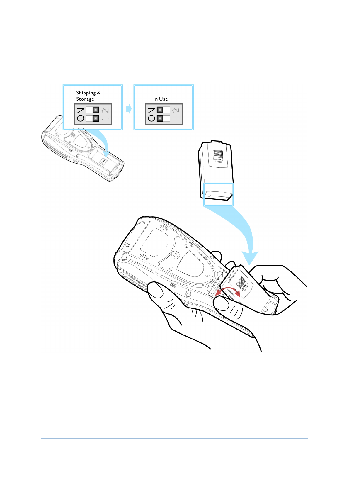
1.1.1 INSTALLING THE BATTERY
When you first receive the package, the rechargeable functionality of the backup battery is turned
off. It is controlled by a DIP switch inside the battery compartment as shown below.
For shipping and storage purposes, save the mobile computer and the main battery in separate
packages, and slide the DIP switch to the OFF position (to your right). This will keep both batteries
in good condition for future use.
Note: Any improper handling may reduce the battery life.
1) Use the stylus (or a sharp-pointed object, such as a pencil) to slide the DIP switch to the ON
position (to your left). Now the internal backup battery can be charged by the main battery.
2) Slide the battery pack into the battery compartment at a proper angle (30°~45°) so that the tabs
on the bottom of the battery are hooked in the grooves of the compartment. Make sure that the
battery is snugly fit into the compartment.
7
Page 18
9500PPC Mobile Computer Reference Manual
3) Hold the mobile computer still and slide the battery latch to lock the battery in the
compartment.
Figure 5: Adjusting DIP
Switch & Installing the
Main Battery
8
Page 19
Chapter 1 Using the 9500PPC Mobile Computer
1.1.2 CHARGING THE BATTERY
The main and backup batteries may not be charged to full for shipment. When you first receive the
package, you will need to charge batteries to full before using the mobile computer.
Note: To charge the batteries to full, it requires approximately 8 hours for the first time. After the
initial charging, it takes only 4 hours to charge the batteries to full.
Because the internal backup battery is constantly charged from the main battery, the initial charging
requires installing the battery pack to the mobile computer and then seating the mobile computer in
the cradle for charging. This will have both the main and backup batteries charged at the same time.
To charge the backup battery, make sure that you slide the DIP switch inside the battery
compartment to the ON position.
Note: For a new battery, make sure it is fully charged before use. Always prepare a spare battery
pack, especially when you are on the road.
1.1.3 UNDERSTANDING THE BATTERY ICONS
The battery pack is the only power source for the mobile computer to work. It also charges the
backup battery on the main board so that the data stored in SRAM can be retained properly.
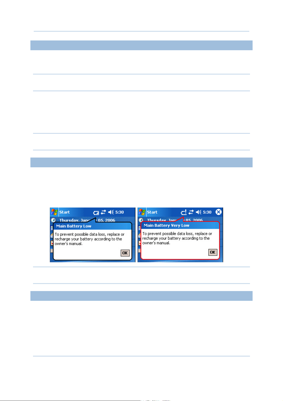
Therefore, when the main battery charge goes low (see below for battery status icon), you need to
replace the battery pack with a charged one or charge it as soon as possible. Most of all, always save
data before it is too late; you should backup important data on a regular basis.
Warning: Data loss may occur with SRAM during low battery condition. Always save data
before running out of power or keep a fresh battery for replacement.
1.1.4 POWER MANAGEMENT
For any portable device, power management is a critical issue especially when you are on the road.
Below are some tips to help you save battery power.
To speed up charging the mobile computer, turn off the mobile computer and seat it in the
cradle.
Bring a second battery pack on the road.
9
Page 20

9500PPC Mobile Computer Reference Manual
Stop wireless connectivity, Bluetooth or 802.11b that is not in use. Refer to the Wireless Power
Manager.
To save power, go to Start > Settings > System tab and select Backlight / Backlight
Control (for backlight settings) or select Power (for power schemes).
Warning: Using backlight, wireless connectivity, and peripherals while on battery power will
substantially reduce battery life.
START > SETTINGS > SYSTEM TAB AND TAP THE POWER ICON
In the Battery tab, you can always monitor the charging status. Watch out for a low battery
charge or discharged battery before you receive a warning message indicating a low battery
condition. A battery bar will show the progress of charging.
In the Wireless tab, you may configure these settings (Flight mode) to save battery power or
avoid causing radio interference, especially when on an airplane or in a hospital. The wireless
signals may come from Bluetooth, or 802.11b, or even both. Here you can select to turn off the
wireless signals from either of them or both. If both the check boxes are selected, it results in
the same behavior when you turn on/off the flight mode from the Connectivity button.
Note: The power to the wireless module is controlled by Wireless Power Manager. The
wireless power settings here are provided only when the wireless power is turned on
through Wireless Power Manager.
In the Advanced tab, you may specify automatic turn-off times for the mobile computer to
conserve power. When the mobile computer is turned off, it means the system is in Suspend
mode, which is ready for use but not in use.
START > SETTINGS > SYSTEM TAB AND TAP THE BACKLIGHT OR BACKLIGHT CONTROL ICON
To conserve more power, you may go to Start > Settings > System tab and select Backlight or
Backlight Control to configure the backlight setting. Refer to section 1.4.1
Adjusting the Backlight.
1.2 MEMORY
Read-only Memory (ROM)
128 megabytes flash memory for storing OS (Windows Mobile 2003SE) and custom application
programs. Yet a small portion of the memory is referred to as DiskOnChip, which can store data
and programs that you wish to retain even after a hardware reset.
Random-access Memory (RAM)
64 megabytes SDRAM for storing and running programs, as well as storing program data. Its
contents will be retained by the backup battery.
Expansion Slot
The mobile computer is equipped with two card slots, one SD and one CompactFlash Type II.
You may upgrade memory by inserting an optional SD or CF memory card.
10
Page 21

Chapter 1 Using the 9500PPC Mobile Computer
1.2.1 CAUTION OF DATA LOSS
When the main battery is removed or drained, the backup battery on the main board is to retain the
contents of SRAM and maintain the OS in suspend mode for at least 6 hours, on condition that the
backup battery has already been fully charged.
If you want to put away the mobile computer for a couple of days, you should be aware that data
loss occurs when both the main and backup batteries discharge completely. Therefore, it is necessary
to backup data and files before putting away the mobile computer!
1.2.2 CHECKING THE STORAGE SPACE
START > SETTINGS > SYSTEM TAB AND TAP THE MEMORY ICON
In the Main tab, it displays the current capacity and usage of the onboard SDRAM, 64 MB.
You may tap, hold, and drag the slider to re-allocate the memory.
SDRAM STORAGE MEMORY (LEFT) PROGRAM MEMORY (RIGHT)
64 MB onboard It refers to the memory allocated
for file and data storage.
It refers to the memory allocated
for running programs.
In the Storage Card tab, it displays the current capacity and usage of the selected memory type,
DiskOnChip, SD or CF card. The DiskOnChip is part of the onboard 128 MB flash memory.
Because the flash memory is non-volatile, data or programs stored in DiskOnChip will not be
erased after a hardware reset.
In the Running Programs tab, it displays the programs that are currently using the Program
memory as indicated in the Main tab. If you receive program errors or find the mobile computer
running slowly, you may need to free memory. Select from the list and stop any or all of the
running programs.
Warning: Always remember to save data before you stop a running program.
START > SETTINGS > SYSTEM TAB AND TAP THE SYSTEM CONSOLE ICON
In the Autorun tab, you may select whether to enable the autorun feature or not when a SD/MMC
card is present. When enabled, executable files stored on the memory card will be executed
automatically once the card is installed.
SD refers to Secure Digital, memory card format based on MMC.
MMC refers to Multi-Media Card, older memory card format.
11
Page 22
9500PPC Mobile Computer Reference Manual
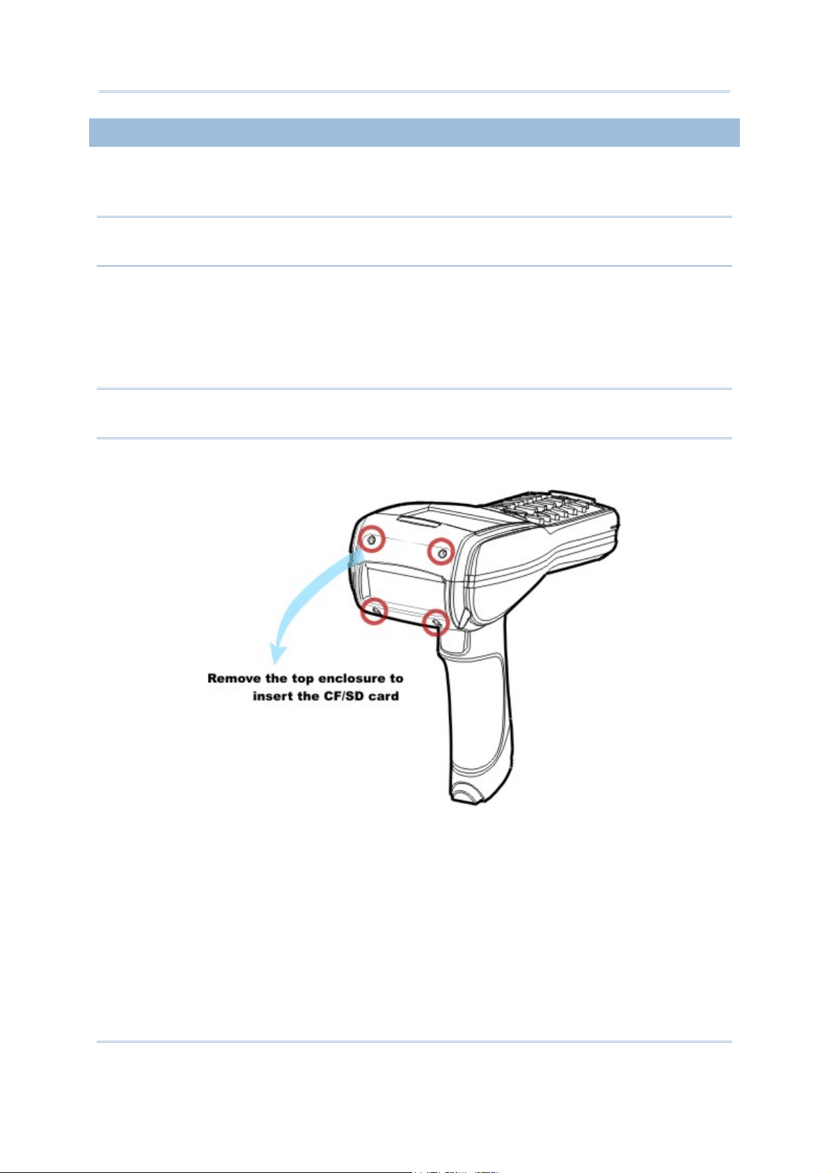
1.2.3 INSERTING THE SD OR CF CARD
When you need to expand memory or add a peripheral, take the following steps to install the CF or
SD card to the mobile computer:
Warning: If not factory-installed, the Ingress Protection rating of enclosures may not be the
same as claimed.
1) Press the [Power] key to turn off the mobile computer.
2) Remove the top enclosure of the mobile computer by unscrewing the four screws.
3) Insert your card properly.
4) Replace the top enclosure and tighten the screws.
Warning: Make sure the mobile computer is set to Suspend mode; otherwise, it may cause
damage to the mobile computer.
Figure 6: Inserting the SD
or CF Card
12
Page 23
Chapter 1 Using the 9500PPC Mobile Computer
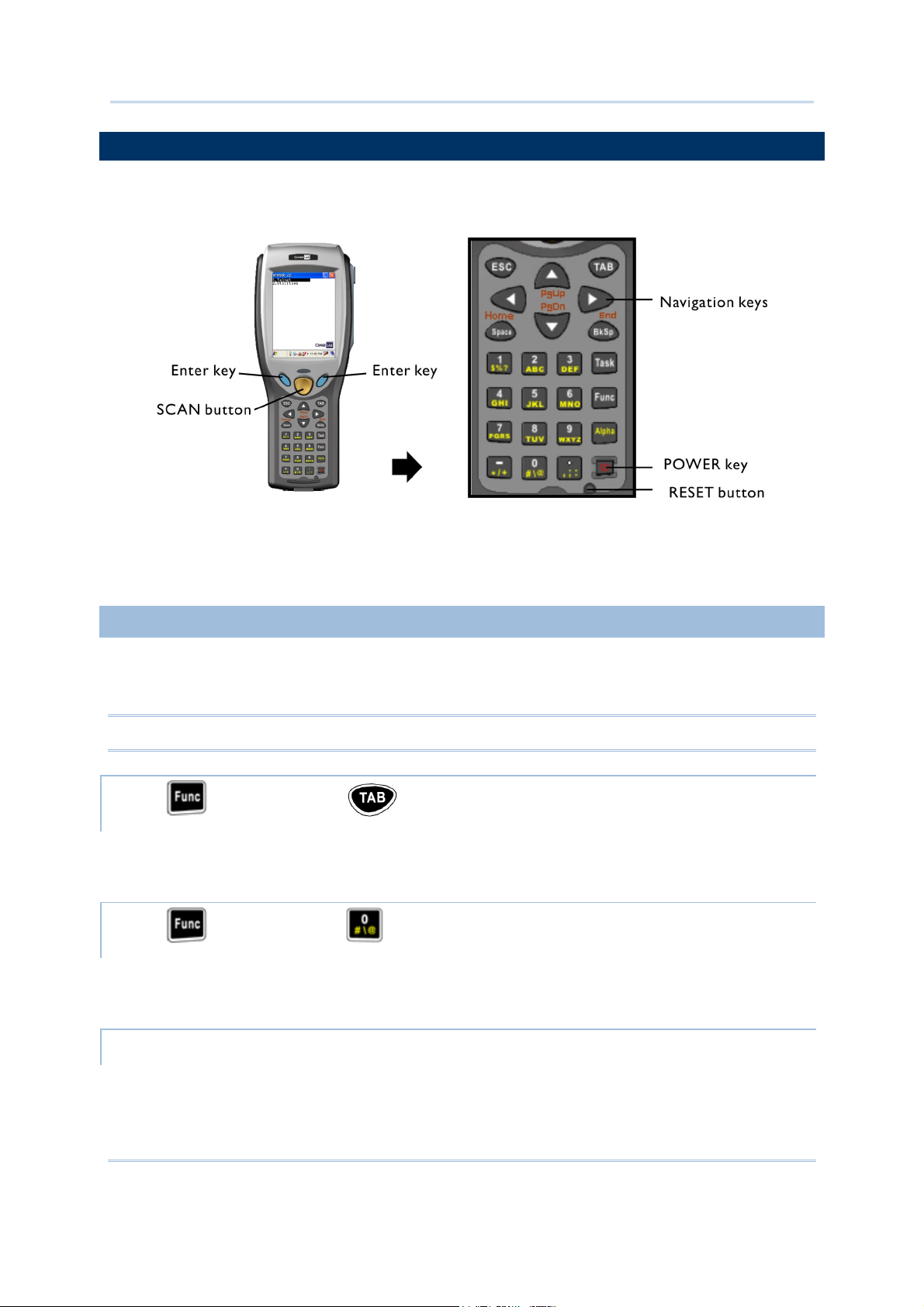
1.3 KEYPAD
The mobile computer is equipped with a physical keypad that consists of 27 keys. Silicon rubber has
been chosen for their durability and prompt feedback.
Figure 7: 27-key Layout
1.3.1 USING THE KEYPAD
The 27-key keypad includes alphanumeric, assorted characters, etc. This keypad is set to numeric
mode by default.
Note: Functionality of keys is application-dependent.
PRESS FIRST, AND THEN
The LED backlight of LCD as well as keypad can be controlled at the same time. It can be toggled
ON/OFF by the key combination: [Func] + [TAB].
PRESS
The LED backlight of keypad is turned off by default. It can be toggled ON/OFF by the key
combination: [Func] + [0].
FIRST, AND THEN
START > SETTINGS > PERSONAL TAB AND TAP THE SOUND & NOTIFICATIONS ICON
In the Sounds tab, select the Hardware buttons to enable the key click.
13
Page 24
9500PPC Mobile Computer Reference Manual
Warning: It is suggested to turn on the keypad backlight while working in a dark area;
however, using backlight while on battery power will substantially reduce battery life.
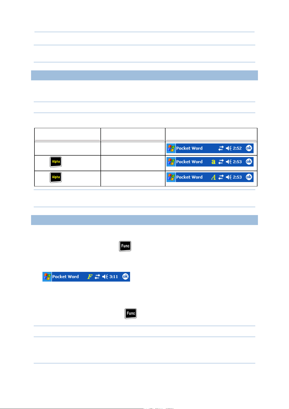
1.3.2 ALPHA KEY
This alphanumeric keypad is set to numeric mode by default. The Alpha key serves as a toggle among
numeric, alpha (lower-case alphabetic), and ALPHA (upper-case alphabetic) input modes.
Note: It is not necessary to hold down the [Alpha] key.
The alpha icon will appear on the navigation bar in a sequence as shown below.
ALPHA KEY INPUT MODE RESULT
N/A Numbers
Small letters
Press one time
Capital letters
Press two times
Note: If you are using the software keypad via SIP, tap CAP (Caps Lock) to toggle between upper
case and lower case alphabetic modes.
1.3.3 FUNCTION KEY
The [Func] (function) key serves as a modifier key.
1) To enable this modifier key, press
A yellow icon of the letter "F" will appear on the navigation bar. This modifier key is hold down
as long as the icon is displayed.
2) Now press another key to get the value of key combination (say, press [1] to get the value of
F1). The icon will go off now.
3) To get the value of another key combination modified by the [Func] key, repeat the above steps.
on the keypad.
4) To abort the key modification, press
again, and the icon will go off.
Note: It is not necessary to hold down the [Func] key.
14
Page 25
Chapter 1 Using the 9500PPC Mobile Computer
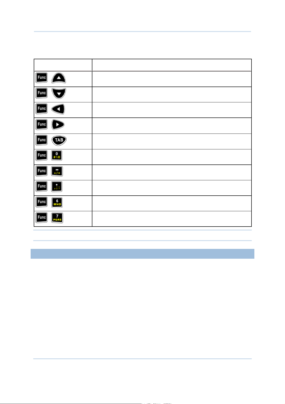
The functionality of each key combination is application-dependent. Below is a list of the factory
setting for a variety of key combinations.
KEY COMBINATION ACTION
PgUp (red-coded): move text up one screenful
,
PgDn (red-coded): move text down one screenful
,
Home (red-coded): move to the beginning of screen or document
,
End (red-coded): move to the end of screen or document
,
Toggle ON/OFF the backlight of LCD as well as keypad
,
Toggle ON/OFF the backlight of keypad only
,
Turn ON the backlight of LCD and decrease its luminosity
,
Turn ON the backlight of LCD and increase its luminosity
,
Increase volume
,
Decrease volume
,
Note: Press the [Func] key first, and then press the second key for a specific function.
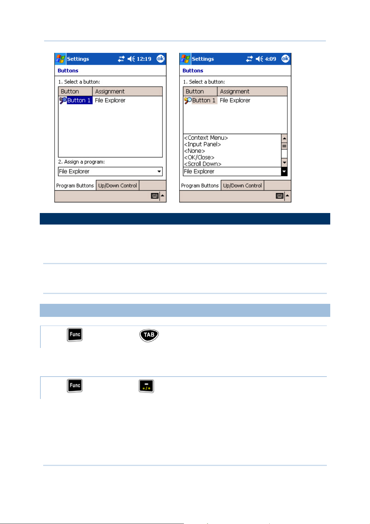
1.3.4 TASK KEY
The [Task] key, identified as “Button 1”, can be programmed as a shortcut key for a specific program
or action. By default, it is set to trigger File Explorer.
1) Tap Start > Settings > Personal tab and select Buttons.
2) In the Program Buttons tab, select Button 1 and assign it to trigger a different program, action,
or <None>.
15
Page 26
9500PPC Mobile Computer Reference Manual
Î
1.4 TOUCH SCREEN
The mobile computer comes with a 3.5" TFT graphic LCD, 320 by 240 pixels resolution (QVGA).
The LED backlight of screen, which helps ease reading under dim environments, can be controlled
manually and automatically.
Warning: Using backlight while on battery power will substantially reduce battery life. It is
suggested to dim the backlight while working in a well-lit area or automatically turn
off the mobile computer when not in use.
1.4.1 ADJUSTING THE BACKLIGHT
PRESS FIRST, AND THEN
The LED backlight of LCD as well as keypad can be controlled at the same time. It can be toggled
ON/OFF by the key combination: [Func] + [TAB].
PRESS
FIRST, AND THEN
The LED backlight of the screen can be turned on and adjusted decreasingly by the key combination:
[Func] + [-]. Keep pressing the key combination ([Func] first, and then [-]) until the luminosity is
decreased to a desired level.
16
Page 27
Chapter 1 Using the 9500PPC Mobile Computer
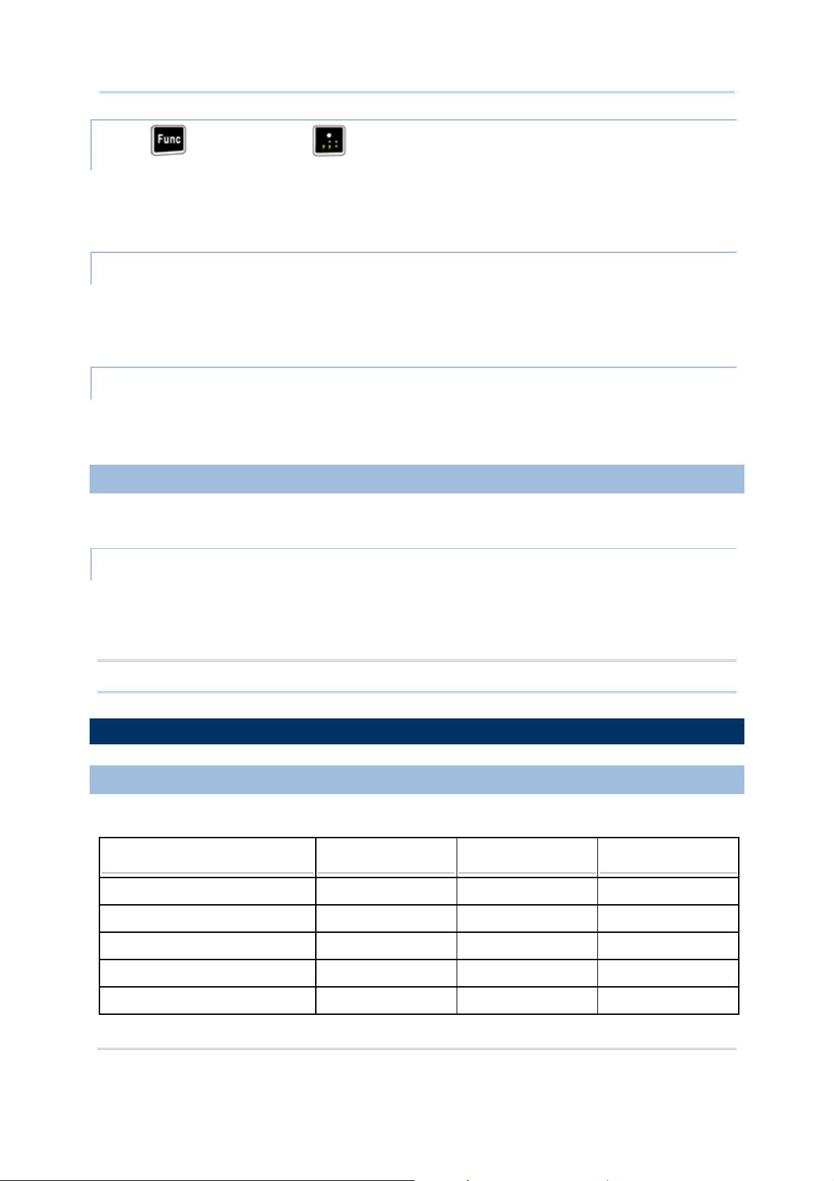
PRESS
FIRST, AND THEN
The LED backlight of the screen can be turned on and adjusted increasingly by the key combination:
[Func] + [.]. Keep pressing the key combination ([Func] first, and then [.]) until the luminosity is
increased to a desired level.
START > SETTINGS > SYSTEM TAB AND TAP THE BACKLIGHT ICON
The backlight can be toggled on and off automatically, either on battery or AC power. To conserve
more power, you may go to Start > Settings > System tab > Power to configure the auto
turn-off setting.
START > SETTINGS > SYSTEM TAB AND TAP THE BACKLIGHT CONTROL ICON
Tap, hold, and drag the slider to manually adjust the luminosity of backlight. Alternatively, you may
select to auto adjust backlight by the battery's capacity.
1.4.2 RE-CALIBRATING THE SCREEN
This LCD is also a touch screen that can be calibrated through screen alignment.
START > SETTINGS > SYSTEM TAB AND TAP THE SCREEN ICON
In the Alignment tab, tap [Align Screen] to start with screen alignment if necessary.
In the Clear Type tab, you may select Clear Type for fonts.
In the Text Size tab, you may tap, hold, and drag the slider to configure text size.
Warning: Do not use any pointed or sharp objects to move against the surface of the screen.
1.5 NOTIFICATIONS
1.5.1 STATUS LED
The dual-color LED on top is used to provide information on the charging status or wireless status.
TASKS GREEN LED RED LED GREEN & RED
Low battery charge --- Flashing ---
Charging 9500PPC --- On ---
Charging done On --- ---
Charging error --- --- Flashing
Wireless signal searching Flashing --- ---
17
Page 28

9500PPC Mobile Computer Reference Manual
1.5.2 AUDIO
The mobile computer is integrated with a mono speaker, a low power transducer type, used for
playing sounds applied to events in Windows and programs, as well as playing audio files such as
.WAV, .MP3 files. In addition, it can be programmed for status feedback.
PRESS
FIRST, AND THEN
The volume of the speaker can be turned on and adjusted increasingly by the key combination:
[Func] + [6]. Keep pressing the key combination ([Func] first, and then [6]) until the volume is
increased to a desired level.
PRESS
FIRST, AND THEN
The volume of the speaker can be turned on and adjusted decreasingly by the key combination:
[Func] + [7]. Keep pressing the key combination ([Func] first, and then [7]) until the volume is
decreased to a desired level.
1.5.3 VIBRATOR
The mobile computer is integrated with a vibrator, which is software programmable for feedback.
This can be helpful when working in noisy environments.
1.6 DATA CAPTURE
A wide variety of scan engines is available for delivering flexibility to meet different requirements.
Depending on the scan engine integrated (check the "Active Device" setting in ReaderConfig), the
mobile computer is capable of scanning barcodes of a number of symbologies that are enabled by
default. If you need to scan barcodes that are encoded in a different symbology, use the Reader
Configuration Utility to enable the symbology first.
Refer to Appendixes for details on scan engine settings.
Note: The mobile computer allows the co-existence of one integrated scan engine and the RFID
reader.
1.7 COMMUNICATIONS
1.7.1 USING THE CRADLE
The cradle is designed for charging and communications at the same time.
1) Place the cradle on a flat and clean surface.
18
Page 29
Chapter 1 Using the 9500PPC Mobile Computer
2) Connect the line of the power adaptor to the power jack on the back of the cradle.
3) Connect the power adaptor to a suitable power outlet.
4) The cradle is ready for charging.
5) Seat the mobile computer in the cradle.
If data communications are desired at the same time, you can establish a USB connection for
ActiveSync with your computer.
Make sure that you have Microsoft ActiveSync installed on your computer before you connect
the USB cable from the cradle to your computer.
Refer to section 2.3
Using ActiveSync.
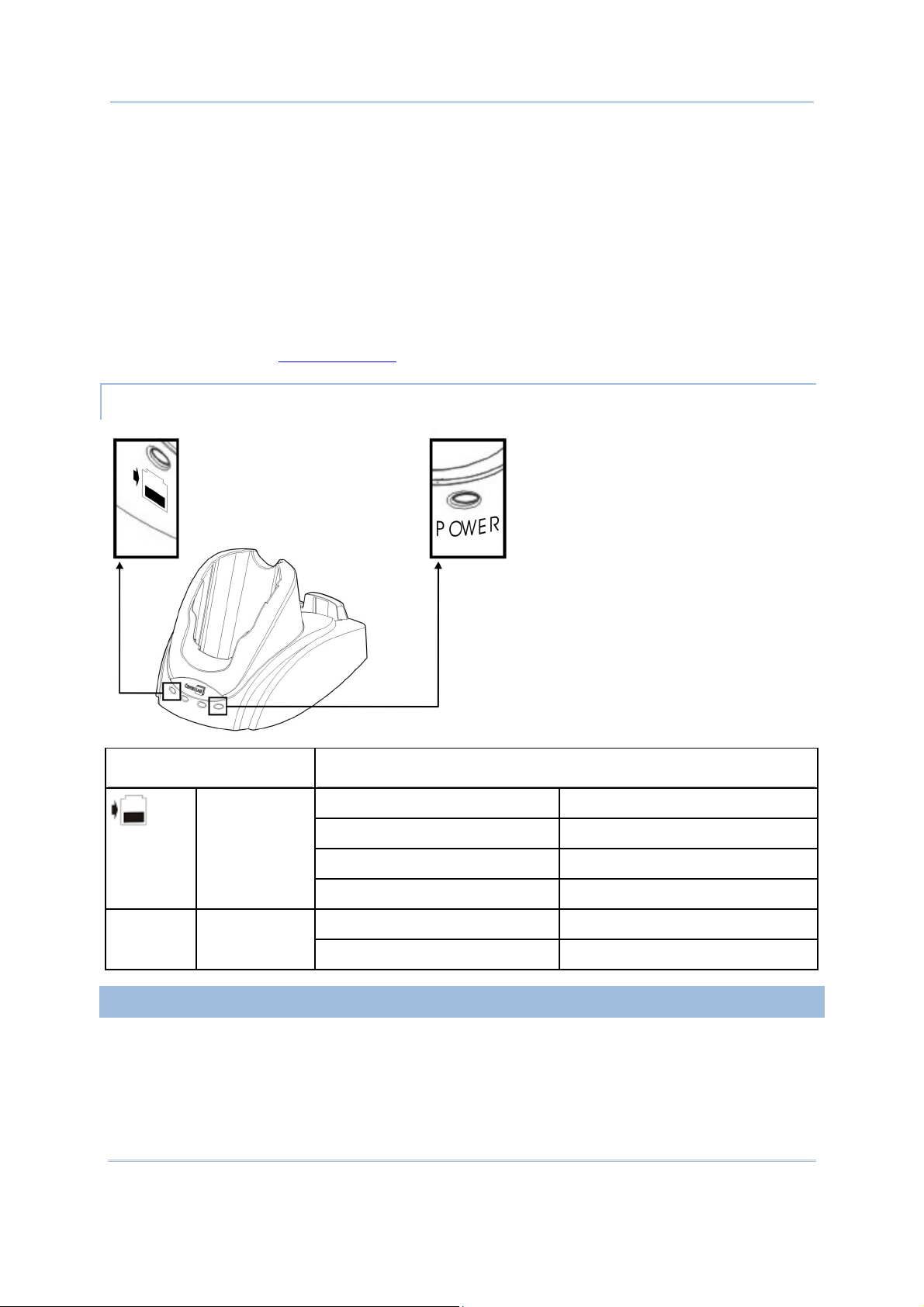
UNDERSTANDING THE STATUS INDICATORS
FRONT PANEL LEDS INDICATION OF CONNECTION STATUS
Charging Status
of Spare
Battery
Solid red Charging spare battery
Solid green Charging done
Flashing (red/green) Error occurs
Off Battery not ready
Solid green Power on POWER Cradle Power
Off Power off
1.7.2 USING WIRELESS NETWORKS
The mobile computer supports state-of-the-art wireless technologies, Bluetooth and 802.11b, so that
it is able to send/receive data in real time in an efficient way.
19
Page 30

9500PPC Mobile Computer Reference Manual
20
Page 31

Chapter 2
LEARNING POCKET PC BASICS
This chapter mainly describes the basic skills to work with the 9500PPC Mobile Computer. The
add-on utilities for applications regarding data collection, processing, and transmission, are
introduced in the following chapters.
The 9500PPC Mobile Computer is specifically designed for real-time data collection in the Windows
Mobile 2003 Second Edition environment. It won't take long for any Windows user to get
familiarized with it. Keep these basic skills in mind and explore this Windows Mobile device at ease.
Single-tap an item to select it.
Tap and hold an item to see a menu that enables tasks, such as cut, copy, rename, delete, etc.
Tap and drag to select multiple items.
To learn more about 9500PPC, go to Start > Help.
IN THIS CHAPTER
2.1 Getting Started ...............................................................................................21
2.2 Finding out the Capabilities of Your Mobile Computer .......................26
2.3 Using ActiveSync ............................................................................................27
2.4 Managing Programs........................................................................................30
2.5 System Reset...................................................................................................36
2.1 GETTING STARTED
When the 9500PPC Mobile Computer is fully charged, you may remove it from the cradle. Then,
press the [Power] key to turn on the mobile computer and wait for the Today screen to come up
after calibrating the screen with the stylus.
If you are using the mobile computer for the first time, there are a couple of things to do after the
desktop comes up.
To select your time zone and set the local time
To align the touch screen
Note: With a focus on delivering data collection and industrial requirements on a portable device,
the 9500PPC Mobile Computer is currently not equipped with an internal microphone and
the IrDA port. Therefore, voice recording and file transfer via infrared (Start > Settings >
Connections tab > Beam) are not supported.
21
Page 32

9500PPC Mobile Computer Reference Manual
SUSPEND MODE
The 9500PPC Mobile Computer functions when it is turned on. This is because the Windows Mobile
2003 Second Edition operating system eliminates the booting process and runs continuously.
Turn On (= Resume from Suspend)
To turn on the mobile computer, simply press the [Power] key.
Turn Off (= Suspend)
To turn off the mobile computer, press the [Power] key again, or select Suspend from the Start
Menu. The system is now ready for use but not in use. This is referred to as Suspend mode or
Standby mode. It means the system is in power-saving status and waiting for user interference.
Warning: In order to save battery power, it is suggested that the mobile computer is set to be
automatically turned off when not in use. Refer to section 1.1.4 Power Management
for more information about saving power.
2.1.1 TODAY SCREEN
The Today screen (desktop) appears when the mobile computer is turned on.
Alternatively, you may tap the Windows logo or the Start button on the top-left corner of the
screen, and then select Today.
Note: To customize the Today screen, go to Start > Settings > Personal tab > Today. In the Items
tab, [Today timeout] refers to the amount of hours of inactivity for the Today screen to
show up automatically.
22
Page 33

Chapter 2 Learning Pocket PC Basics
2.1.2 NAVIGATION BAR
The navigation bar is at the top of the Today screen, which consists of the Start button and a
number of status icons.
OPTIONS DESCRIPTION
Start button Tap to run a program or configure settings.
Start menu: list up to 7 programs
Recent programs: list up to 5 programs
Provides access to available programs in the directory: My Device\
Windows\Start Menu\Programs
Provides access to system settings
Status icons
Connectivity
Volume
Time and Next Appointment
Close button Tap to close an active window.
Tap to access settings of connections.
Turn on flight mode/Turn off flight mode
when wireless power is enabled
Tap to adjust volume or mute the mobile
computer.
Tap to view next appointment and battery
status.
Note: To configure the Start menu, go to Start > Settings > Personal tab and select Menus.
23
Page 34

9500PPC Mobile Computer Reference Manual
2.1.3 TASKBAR
The taskbar is at the bottom of the Today screen, where the New button allows the creation of
different jobs.
When in an application, part of the taskbar will become the Command Bar which contains buttons
and menus for performing tasks in the program.
Note: To configure the New menu, go to Start > Settings > Personal tab and select Menus.
UNDERSTANDING THE BUTTONS OR ICONS ON THE TASKBAR
From the Today screen, the taskbar also displays shortcuts to the following items.
BUTTON SHORTCUT TO MEANING
NEW
New menu Tap to create a job
Wireless Power
Manager
Tap to run Wireless Power Manager.
Options include WLAN Power and Bluetooth Power.
24
Page 35

Chapter 2 Learning Pocket PC Basics
Manager
Bluetooth
Bluetooth Power is turned off.
Bluetooth Power is turned on. Tap to run Bluetooth Manager.
Wi-Fi Utility WLAN Power is turned off (driver not loaded).
WLAN Power is turned on. Tap to run Wi-Fi Utility.
WLAN connected.
Reader Cfg Tap to configure the barcode or RFID reader.
Options include BC Reader and RFID Reader (if installed).
USB
Connected to
The mobile computer is connected to a computer via its USB
cradle. Tap to configure USB connection.
Note: If no Wi-Fi button, go to Start > Programs and run the program Swluce. If no barcode
button, go to Start > Programs and run the program ReaderCfg.
2.1.4 INPUT METHODS
Data entry can be performed by the following methods:
Type with the physical keypad.
Scan barcode or RFID tag in applications, e.g. Pocket Word, Pocket Excel, CipherLab's
Application Generator, etc.
Tap or write using SIP (Soft Input Panel)
Draw in some applications, e.g. Note and Pocket Word
USING THE SOFT INPUT PANEL (SIP)
Tap the SIP button on the Command Bar to select a SIP mode or hide the input panel. To select a
SIP mode, tap the arrow next to the SIP button.
In each mode, the characters appear as typed text on the screen.
25
Page 36

9500PPC Mobile Computer Reference Manual
OPTIONS DESCRIPTION
Block Recognizer To write in the input box.
Keyboard To type using the virtual keyboard.
Letter Recognizer To write in the input box.
Transcriber To write freely on the screen in applications, such as Notes, Pocket
Word, etc.
2.2 FINDING OUT THE CAPABILITIES OF YOUR MOBILE COMPUTER
1) Go to Start > Settings > System tab and select System Console to obtain essential system
information.
2) In the System Information tab, select an item to view from the drop-down menu.
Note: Not all the Bluetooth services listed in the system information are supported currently.
DEVICE CONFIGURATION CODE
The device configuration of 9500PPC Mobile Computer is displayed in 4 digits: xxxx
Take the screenshot of System Properties above for example. Its device configuration is “3410”,
which means the 27-key mobile computer has equipped with the following parts:
A scan engine that employs 2D imager
Integrated Bluetooth and Wi-Fi modules
An RFID reader
DEVICE CODE MODULAR COMPONENT TYPES
1st digit Reader module 0= none
1= CCD scan engine
2= Laser scan engine
3= 2D scan engine
4= Long Range Laser scan engine
5= Extra Long Range Laser scan engine
2nd digit Wireless module 4= Bluetooth + 802.11b
5= Bluetooth only
3rd digit RFID module 0= none
1= RFID reader
4th digit Reserved ---
26
Page 37

Chapter 2 Learning Pocket PC Basics
2.3 USING ACTIVESYNC
ActiveSync is used to synchronize information between the 9500PPC Mobile Computer and your
desktop computer, to install programs on the mobile computer, and to backup and restore the
mobile computer.
To download the up-to-date version of the program, you may need to go to Microsoft's official
web site for Windows Mobile devices as shown below.
http://www.microsoft.com/windowsmobile/default.mspx
After downloading and installation, run the program. For detailed information on the program,
you may click the Help menu, and then select the Microsoft ActiveSync Help.
The Microsoft ActiveSync program has to be installed on your desktop computer first.
1) Run the Microsoft ActiveSync program on your desktop computer.
2) On the File menu, click [Connection Settings]. If you want to skip settings, click [Get Connected]
instead.
3) Click to select the USB connection check box as shown above.
4) Click [OK] to go back to step 2. Click [Get Connected] now.
27
Page 38

9500PPC Mobile Computer Reference Manual
2.3.1 SYNCHRONIZATION WITH YOUR COMPUTER
1) Follow these instructions for initial ActiveSync operation:
Connect the USB cable from the cradle to your computer.
Connect the power cable from the cradle to a nearby power outlet.
Turn on the mobile computer and seat it in the cradle.
2) Your computer will automatically detect the USB device. Click [OK] when the connection is
established.
3) Select which partnership to set up. If you want to synchronize data between the mobile
computer and your personal computer, select Standard Partnership; otherwise, select Guest
Partnership.
4) Wait a few seconds for the mobile computer to get connected (and synchronized if a Standard
Partnership is selected).
Note: For ActiveSync via Bluetooth, refer to the Bluetooth Manager.
2.3.2 ADD/REMOVE PROGRAMS
Click [Add/Remove Programs] from the Tools Menu so that you can proceed to install a program
that is designed to be used on a mobile device. If a user program is no longer desired, you may
remove it from the system. Click [Add/Remove Programs] from the Tools Menu so that you can
un-install a program that is designed to be used on a mobile device.
ALTERNATIVE TO INSTALL NEW PROGRAMS (COPY & PASTE)
Alternatively, you may install a new program manually.
5) When connected, open the Microsoft ActiveSync window on your desktop computer.
6) Click the Explorer button from the toolbar.
7) Navigate to the target folder, e.g. the Programs folder (My Device\Windows\Start
Menu\Programs), depending on where you wish to access the program.
8) Navigate through file folders on your computer to find the new program (.CAB, .EXE, etc.)
28
Page 39

Chapter 2 Learning Pocket PC Basics
9) Right-click the program and select [copy] from the pop-up menu.
10) Back to the target folder in step 3. Right-click anywhere blank and select [Paste] from the pop-up
menu.
11) On the mobile computer, go to Start > Programs and the new program will appear.
ALTERNATIVE TO REMOVE PROGRAMS
When you install a program, it will appear in the list of installed programs as shown below. If a user
program is no longer desired, you may remove it from the system.
Note: If the program does not appear in the list of installed programs, you may use File Explorer to
locate it. Tap and hold the program, and select [Delete] from the pop-up menu.
1) Go to Start > Settings > System tab and select Remove Programs.
2) Tap the name of the program that you want to delete.
3) Tap [Remove].
4) Tap [Yes] to un-install the program.
If the program files are still in use, you need to stop the program first.
Go to Start > Settings > System tab and select Memory. Check the list in the Running
Programs tab.
Note: You may need to remove programs in order to free the storage memory.
2.3.3 BACKUP/RESTORE
To best protect your work, you should regularly back up information on your mobile computer. You
can perform a backup by during the ActiveSync operation. The backup file is stored on your desktop
computer.
The backup file contains all files, databases, personal information manager (PIM) information as well
as SDRAM-based programs.
29
Page 40

9500PPC Mobile Computer Reference Manual
Note: Alternatively, you can restore data using the Backup Utility program if a backup job is
carried out periodically.
2.4 MANAGING PROGRAMS
2.4.1 QUICK LAUNCH A PROGRAM
Tap the Start button to view the Start Menu. To quick launch a program, tap it.
If you wish to quick launch a new program, add it to the Start Menu directly or add it to the
directory My Device\Windows\Start Menu. To add a new program or subfolder to the Start
menu or Programs folder, you can either use File Explorer or ActiveSync.
File Explorer: to move the program by [Copy] and [Paste Shortcut].
ActiveSync on the desktop computer: to create a shortcut to the program, and place the
shortcut in the Programs folder.
Warning: To avoid making any changes to the program configurations by accident, we
recommend you to use [Copy] and [Paste Shortcut] rather than [Cut] and [Paste].
COSTOMIZING THE START MENU
1) Go to Start > Settings > Personal tab and select Menus. In the Start Menu tab, select from
the program list to add any desired program to the Start menu. Because the Start menu allows
seven programs at maximum, you may need to clear some check boxes before you can select
new programs.
2) Tap OK to save new settings. The rest on the list will appear in Start > Programs.
30
Page 41

Chapter 2 Learning Pocket PC Basics
3) Tap the Start button to verify if the program appears in the Start menu.
Note: The Start menu can list seven programs at most.
USING FILE EXPLORER TO ADD A PROGRAM TO START MENU
1) Go to Start > Programs and select File Explorer. Alternatively, you can press the [Task] key
on the keypad to launch File Explorer.
2) Navigate through file folders to find the program you desire.
3) Tap and hold the program to select [Copy] from the pop-up menu. (right below)
31
Page 42

9500PPC Mobile Computer Reference Manual
4) Navigate to the Programs folder (My Device\Windows\Start Menu\Programs).
5) Tap and hold anywhere blank on the screen to select [Paste Shortcut] from the pop-up menu.
(right above) The new program will be added to the Programs folder.
6) Go to Start > Settings > Personal tab and select Menus. The new program will appear now.
USING ACTIVESYNC TO ADD A PROGRAM TO START MENU
1) When connected, open the Microsoft ActiveSync window on your desktop computer.
2) Click the Explorer button from the toolbar.
3) Navigate through file folders to find the program you desire. (right above)
4) Right-click the program and select [Create Shortcut] from the pop-up menu.
5) Right-click the shortcut and select [Cut] from the pop-up menu.
6) Navigate to the Programs folder (My Pocket PC\Windows\Start Menu\Programs).
7) Right-click anywhere blank on the window and select [Paste] from the pop-up menu. The new
program will be added to the Programs folder.
32
Page 43

Chapter 2 Learning Pocket PC Basics
8) On the mobile computer, go to Start > Settings > Personal tab and select Menus. The new
program will appear now.
Note: [Create Shortcut], [Cut], and [Paste]: The same result can be performed by [Copy] and
[Paste Shortcut].
2.4.2 CREATE A FOLDER
USING FILE EXPLORER TO ADD A NEW FOLDER
1) Go to Start > Programs and select File Explorer. Alternatively, you can press the [Task] key
on the keypad to launch File Explorer.
2) Navigate through file folders to find where you wish to create a new folder.
3) Right-click anywhere blank on the window and select [New Folder] from the pop-up menu.
A subfolder will be created.
USING ACTIVESYNC TO ADD A NEW FOLDER
1) When connected, open the Microsoft ActiveSync window on your desktop computer.
2) Click the Explorer button from the toolbar.
3) Navigate to the target folder where you wish to create a new folder.
4) Right-click anywhere blank on the window and select [New Folder] from the pop-up menu.
A subfolder will be created.
2.4.3 LOCATE A FILE
START > PROGRAMS AND TAP THE FIND ICON
1) Go to Start > Programs and select Find to locate a file or an item.
2) In the Find box, enter the file name, word, or other information you want to search for.
If you have looked for this item before, tap the drop-down menu and select it.
3) In the Type box, select a data type to help narrow your search.
If the data type of your file is other than listed, you may try [Larger than 64 KB].
However, if such file is less than 64 KB, it will not be searchable.
4) Tap [Go]. It will start to search through My Documents folder and its subfolders, as well as
DiskOnChip.
5) In the Results list, tap the item you want to open.
In the sample screen below, the first file is stored in My Documents folder, and the second one is
in DiskOnChip as indicated by its icon.
33
Page 44

9500PPC Mobile Computer Reference Manual
USING FILE EXPLORER TO LOCATE A FILE OR AN ITEM
1) Go to Start > Programs and select File Explorer. Alternatively, you can press the Task key
on the keypad to quick launch File Explorer.
2) Tap the folder list, which is labeled My Documents by default, and then the folder that you want
to view, for example, DiskOnChip. (right above)
3) To open an item, tap it.
To quickly cut, copy, rename, delete, or move an item, tap and hold (right above).
To select multiple items, tap and drag.
34
Page 45

Chapter 2 Learning Pocket PC Basics
2.4.4 SWITCH AMONG PROGRAMS
To run a desired program or switch among programs, tap Start and select a program. Alternatively,
you may go to Start > Settings > System tab and select Memory. In the Running Programs tab,
select a program that you want to use and tap [Activate] now.
Warning: In order to use memory in a more efficient way, you are recommended to stop a
running program or exit a program when it is not desired any longer.
2.4.5 CLOSE OR EXIT A PROGRAM
In general, the system manages memory automatically, and there is no need to exit a program in
order to open another or to conserve memory. However, random access memory (SDRAM) may be
used up when running too many programs. As a result, it will slow down the operation or cause
program errors. In that case, you should stop one or more running programs to free memory.
Tap on the navigation bar to close an active window, a dialog box, or a running application.
Be aware that every time when you tap Close, it actually does not exit the program. The
program is still running on the background, and therefore, the memory is not freed.
Tap on the navigation bar to save the current settings and exit the application (or minimize
the window in some applications).
Note: Some programs, such as Swluce and the Reader Configuration Utility (ReaderCfg.exe), may
create an associated icon on the taskbar. You may tap the icon and select [Exit] from the
pop-up menu.
35
Page 46

9500PPC Mobile Computer Reference Manual
In order to use memory in a more efficient way, you are recommended to exit a program when it is
not desired any longer.
Warning: Always remember to save data or settings before you exit a program.
START > SETTINGS > SYSTEM TAB AND TAP THE MEMORY ICON
Go to Start > Settings > System tab and select Memory. In the Running Programs tab, select a
program that you do not want to use any more and tap [Stop]. Alternatively, you may select to stop
all the programs that are running.
2.5 SYSTEM RESET
Reset the mobile computer when it stops responding to input.
Software Reset: Simply press the [Reset] button.
Hardware Reset: Press the [Reset] button and the [Power] key at the same time.
Warning: Never perform a hardware reset unless a software reset cannot solve your
problems.
2.5.1 SOFTWARE RESET (WARM REBOOT)
A software reset, also known as a warm boot, will restart the mobile computer and keep all the
saved files. To perform a software reset, use the stylus to press the [Reset] button. During
operation, the removal of main battery will start a software reset too.
Warning: Data loss may occur when files are not properly closed before a software reset.
2.5.2 HARDWARE RESET (COLD REBOOT)
A hardware reset, also known as a cold boot, will restart the mobile computer too. However, it
performs a full restore of the mobile computer to its factory settings and initializes SDRAM. To
perform a hardware reset, press the [Power] key and [Reset] button at the same time. Data and
program files stored in SDRAM will be erased after a hardware reset. But you can restore data that
is previously synchronized with your computer by performing an ActiveSync operation. Alternatively,
you can restore data using the Backup Utility program if a backup job is carried out periodically.
Warning: Only the files stored in the Flash File System are retained during a hardware reset.
36
Page 47

t
Chapter 3
PERSONALIZING THE 9500PPC MOBILE COMPUTER
In this chapter, a brief on the system settings is provided for your reference.
Note: User settings are stored in SDRAM and will be overwritten by the system defaults after a
hardware reset.
IN THIS CHAPTER
3.1 Changing Personal Settings ......................................................................... 37
3.2 Changing System Settings ............................................................................ 38
3.3 Changing Connection Settings ................................................................... 40
3.1 CHANGING PERSONAL SETTINGS
Go to Start > Settings > Personal tab. Here you may set up your personal profile that includes
personal information, preferred configuration settings, etc.
ITEMS DESCRIPTION
Buttons
37
Program Buttons tab: Customize [Button 1],
keypad of your mobile computer, to open your most used program. By default,
pressing the [Task] key will invoke File Explorer.
he [Task] key on the physical
Page 48

9500PPC Mobile Computer Reference Manual
Up/Down Control tab: Adjust the delay and repeat rates of the Up/Down
control scrolls.
Input
Menus
Owner
Information
Password
Sounds &
Notifications
Today
Input Method tab: Customize the input method via soft input panel (SIP). The
same options can be accessed by tapping the arrow next to the SIP button and
then Options.
Word Completion tab: Make use of this feature to facilitate input.
Options tab: More general features. Voice recording is not applicable.
Start Menu tab: Select program shortcuts that will appear on the Start menu.
New Menu tab: Select items that will appear on the New button menu when it
is turned on.
Identification/Notes tab: Enter your contact information or notes.
Options tab: Select to display your identification information or notes when it is
turned on.
Password tab: Apply password protection to limit access to the mobile
computer.
Hint tab: Enter a password hint as a reminder.
Sounds tab: Configure sounds for specific actions, events, programs, etc.
Notifications tab: Select to play sounds as notifications for some events.
Appearance tab: Customize the theme and background of the Today screen.
Items tab: Select items that will appear on the Today screen, and configure
Today timeout.
3.2 CHANGING SYSTEM SETTINGS
38
Page 49

Chapter 3 Personalizing the 9500PPC Mobile Computer
Go to Start > Settings > System tab. Here you may verify, and sometimes make changes to,
system parameters. Tap an icon to configure system settings by category.
ITEMS
About
Backlight
BackLight
Control
Certificates
Clock &
Alarms
DESCRIPTION
Version tab: It displays information of OS software, processor, etc.
Device ID tab: You may enter a name and description for identifying the mobile
computer.
Copyrights tab: It displays important statements on copyrights.
Battery Power tab: You may configure when to turn on/off the backlight when
on battery power.
External Power tab: You may configure when to turn on/off the backlight when
on external power (the mobile computer
charging).
being seated in the cradle for
You may use the slider to adjust the brightness of the LCD backlight. In
addition, you may select to auto adjust it by the battery's capacity.
Personal tab: You may use personal certificates to establish your identity when
logging onto a secured network.
Root tab: You may use root certificates to establish the identity of other
computers such as servers.
Time tab: You may have at most two time zones, one is Home-based system
time, and the other can be the place you visit often.
Alarms tab: You may set up at most three alarms to wake you up or as a
reminder.
Memory
Power
Regional
Settings
Remove
Programs
Main tab: You may use the slider to adjust the SDRAM allocation.
Storage Card tab: You may view the memory occupation of DiskOnChip
(flash-based) or any storage card.
Running Programs tab: You may activate or stop any program from the list.
Battery tab: You may view the current charge of main and backup batteries.
Wireless tab: You may configure to turn on/off the wireless signals individually.
Advanced tab: You may configure to turn off the device when it is idle for a
specific period of time, either on battery or external power.
Region tab: You may customize the appearance and formatting to your
geographic region.
Number tab: You may further customize the number formats.
Currency tab: You may further customize the currency formats.
Time tab: You may further customize the time format.
Date tab: You may further customize the date format.
You may remove programs that are stored in SDRAM.
39
Page 50

9500PPC Mobile Computer Reference Manual
Screen
Alignment tab: You may perform screen alignment.
Clear Type tab: You may apply Clear Type fonts.
Text Size tab: You may use the slider to adjust the text size.
System
Console
System Information tab: It displays important system information, such as
software version, supported Bluetooth profiles, etc.
Power Manager tab: You may change the CPU speed and apply Key Lock to
prevent unintended operation.
Autorun tab: You may configure the autorun feature of SD/MMC card.
3.3 CHANGING CONNECTION SETTINGS
Go to Start > Settings > Connections tab. Here you may verify or manually set up connections.
Tap an icon to configure network settings by category.
ITEMS DESCRIPTION
Beam
Connections
It is not applicable because the mobile computer
port.
Tasks tab: You may configure two groups of connections settings, My ISP and
My Work Network.
is not equipped with any IrDA
Advanced tab: More options.
Network
Cards
Wireless tab (if Wi-Fi power is enabled): You may configure wireless networks.
Network Adapters tab: You may configure network adapters.
40
Page 51

Chapter 4 Using Applications
Chapter 4
USING APPLICATIONS
The 9500PPC Mobile Computer provides several utilities and key applications which are made
accessible from the Today screen or the taskbar.
Wireless Power Manager lets you determine whether the power is supplied to the Bluetooth
or WLAN module, along with its associated driver installed.
Bluetooth Manager lets you configure the Bluetooth settings and use the Bluetooth services
provided on the remote devices.
Wi-Fi Utility lets you configure WLAN settings and perform a site survey.
ReaderCfg lets you manage the barcode or RFID reader.
Backup Utility lets you manipulate the way to backup programs and data.
IN THIS CHAPTER
4.1 Wireless Power Manager............................................................................. 41
4.2 Bluetooth Manager ........................................................................................44
4.3 Wi-Fi Utility.....................................................................................................57
4.4 Reader Configuration Utility.......................................................................62
4.5 Backup Utility.................................................................................................. 64
4.6 Terminal Service Client................................................................................68
4.1 WIRELESS POWER MANAGER
Wireless Power Manager is a control panel applet, which allows you to choose and enable the
wireless connectivity, WLAN (802.11b) and/or Bluetooth. That is, the power to the wireless module
is turned on and the software driver is installed. After the initialization process, run Bluetooth
Manager or Wi-Fi Utility for the use of Bluetooth services and 802.11b connectivity respectively.
However, when both Bluetooth and 802.11b are enabled on battery power, the main battery charge
will drop down substantially.
For up-to-date status information on connections, tap the Connectivity button at the top of the
Today screen.
Note: You may need to turn off the wireless power or simply stop the wireless signals at times, in
order to conserve battery power, or in situations where the use of radio is prohibited, such
as on airplanes, in hospitals, etc.
Tap on the taskbar and select [WLAN Power] or [Bluetooth Power]. If it is ticked, the specific
wireless connectivity is enabled. Otherwise, it is disabled.
41
Page 52

9500PPC Mobile Computer Reference Manual
START > SETTINGS > SYSTEM TAB AND TAP THE POWER ICON
It results in the same behavior as you go to Start > Settings > System tab and select Power.
In the Wireless tab, you may clear the check box of Bluetooth and/or 802.11b to disable the wireless
connectivity. To enable it again, select any of the check boxes and turn on the wireless signals.
Note: The wireless power settings are provided only when the wireless power is turned on through
the Wireless Power Manager.
4.2.1 CONNECTIVITY STATUS
For the Connectivity button, its icon may change to indicate different status. However, no specific
icon is used to indicate whether Bluetooth is enabled or not. Instead, you will need to check the
Bluetooth button on the taskbar.
ICON MEANING
USB Connected Bluetooth enabled Wi-Fi enabled
Yes N/A No
No N/A No
Depends N/A Yes
42
Page 53

Chapter 4 Using Applications
4.2.2 FLIGHT MODE
This flight mode setting is provided only when the wireless power is turned on through Wireless
Power Manager.
TURN ON FLIGHT MODE
When the flight mode is turned on, it immediately stops the use any wireless connections, Bluetooth
and Wi-Fi, which could possibly interfere with other equipment especially when on an airplane or in
a hospital. However, you will find that the wireless power is still enabled (ticked) in Wireless
Power Manager.
Tap the Connectivity button, and then tap Turn on flight mode. Wireless signals will be stopped
temporarily and can be recovered later by tapping Turn off flight mode.
It results in the same behavior as you go to Start > Settings > System tab, select Power, and in
the Wireless tab select Wireless signals off (Flight mode).
TURN OFF FLIGHT MODE
Tap the Connectivity button, and then tap Turn off flight mode to restart the wireless
connection.
It results in the same behavior as you go to Start > Settings > System tab, select Power, and in
the Wireless tab select Wireless signals on.
43
Page 54

9500PPC Mobile Computer Reference Manual
4.2 BLUETOOTH MANAGER
Bluetooth Manager is a utility that helps you access and manage the available Bluetooth services
efficiently.
When connecting two Bluetooth-enabled devices, one must discover the other first, and then a
passkey (or link key) is requested for pairing (or bonding). After pairing, a relationship is created for
quick connect in the future. Unless you unpair these two devices, there is no need to enter a passkey
every time they connect.
In order to successfully set up the Bluetooth connection between a Bluetooth device and the mobile
computer, you must make sure that:
The matching Bluetooth services are configured correctly on the Bluetooth device, such as
availability (Startup Automatically or Manually) and Secure Connection.
The Bluetooth power is enabled both on both devices.
The Bluetooth connection is initiated either by the Bluetooth device or the mobile computer
itself. For some Bluetooth Serial Port application, such as ActiveSync, the connection must be
initiated from the mobile computer.
4.2.1 BLUETOOTH PROFILES SUPPORTED
The supported Bluetooth profiles are:
Generic Object Exchange Profile (GOEP)
Serial Port Profile (SPP)
Object Push Profile (OPP)
File Transfer Profile (FTP)
Dial-Up Networking Profile (DUN)
Synchronization Profile (SP)
Note: The "Serial Port on COM8" is registered as a server port on the mobile computer by default,
and can be accessed only when the connection is initiated by the computer.
9500PPC AS A CLIENT
The mobile computer acts as a Client and connects to another Bluetooth device, e.g. your computer,
for available services.
The mobile computer is capable of the following tasks:
Synchronize with your computer by using ActiveSync via Bluetooth.
Send a PIM item, such as a contact, to your computer by using Beam Contact.
Send a file to your computer by using Beam File.
Receive a PIM item from your computer and store it in associated folder.
Receive a file or message from your computer and store it in My Documents folder.
44
Page 55

Chapter 4 Using Applications
9500PPC AS A SERVER
The mobile computer acts as a Server that provides services to another Bluetooth device.
For example, your computer is capable of the following tasks after having established a connection
with the mobile computer:
Connect to COM8 on the mobile computer for a serial link. (Serial Port on COM8)
Send a PIM item to the mobile computer. (OBEX Object Push service)
Send a file to the mobile computer. (FTP service)
Receive a PIM item from the mobile computer where Beam Contact is used.
Receive a file from the mobile computer where Beam File is used.
Note: A file or message received on the mobile computer will be stored in My Documents folder,
while a contact will be stored in the Contacts folder.
DISCOVERING BLUETOOTH SERVICES
You may discover the services by clicking My Bluetooth Places on the desktop of your computer.
Choose the following Bluetooth tasks: "Search for devices in range" or simply "View devices in
range". Click Entire Bluetooth Neighborhood and select the device name representing the
mobile computer. The services supported on the mobile computer will be displayed on the right
pane of the window.
Note: For ActiveSync operation, make sure the Bluetooth Serial Port service is provided on your
computer.
45
Page 56

9500PPC Mobile Computer Reference Manual
4.2.2 STARTING BLUETOOTH SERVICES
1) Tap the rocket button on the taskbar and select [Bluetooth Power].
2) When the Bluetooth button
becomes , it indicates the Bluetooth power is turned on.
Note: In Wireless Power Manager, Bluetooth is enabled if it is ticked; otherwise, it is disabled.
However, it may be interfered by the flight mode switching of Connectivity status.
3) Tap it to configure the Bluetooth settings.
POWER
This option is unavailable for it is controlled by Wireless Power Manager. It simply indicates
the Bluetooth power status.
DEVICE ID
You may rename the mobile computer. Usually a friendly Bluetooth name.
CONNECTIONS
[ON] is selected by default, for making connection to a remote device. (9500PPC as Client)
[DISCOVERABLE] must be selected if you wish the mobile computer to be discovered by
other devices. (9500PPC as Server)
Note: Select [DISCOVERABLE] if you want the mobile computer to provide the Bluetooth services
to a remote device at the same time. Any Bluetooth-enabled devices will be able to discover
the mobile computer within range.
46
Page 57

Chapter 4 Using Applications
STOPPING BLUETOOTH SERVICES
You may need to stop using the Bluetooth services, in order to conserve battery power, or in
situations where the use of radio is prohibited, such as on airplanes, in hospitals, etc.
Tap Wireless Power Manager and turn off the power to the Bluetooth module.
Tap the Connectivity button on the navigation bar and turn on Flight Mode to stop the Bluetooth
signals.
4.2.3 DISCOVERING BLUETOOTH DEVICES
Here is the Bluetooth paired device list. It shows any previously paired devices.
SEARCH NEW DEVICES
If it is blank, tap [Search New Device] to discover any Bluetooth-enabled devices within range. It will
generate a list of discovered devices. Select one device from the list. It will start the pairing
procedure to establish a trusted relationship between the device and the mobile computer.
1) In the Pair tab (left below), tap [Search New Device] to discover your computer.
2) It then displays discovered devices (right below). Tap your computer.
3) A Bluetooth status icon appears on the navigation bar, and a balloon pops up to ask permission.
Tap [Yes] to add your computer to the frequent device list.
47
Page 58

9500PPC Mobile Computer Reference Manual
PAIR DEVICES
1) In the Passkey box, enter your pass key for pairing with your computer. Tap [Next].
2) On your computer: a Bluetooth PIN Code Required balloon (right above) is displayed over the
notification area when a connection is attempted if Secure Connection is enabled. Click the
balloon to proceed.
3) On your computer: a Bluetooth PIN Code Request Dialog box is displayed. In the Bluetooth PIN
Code box, enter your passkey as in Step 4. Tap [OK].
48
Page 59

Chapter 4 Using Applications
4) After pairing successfully, a dialog box (left below) prompts whether you want to register a new
Bluetooth serial port for your computer. Tap [No] if you do not want to use the Bluetooth Serial
Port service.
If you do not want to change the name of your computer, tap [Finish]. (right below)
5) The Bluetooth connection has been set up successfully. Tap [ok] to close the window displaying
the discovered devices. (left below)
6) The paired device will be displayed on the frequent device list. Tap [ok] to close the window.
(right below)
49
Page 60

9500PPC Mobile Computer Reference Manual
7) You may proceed to run the application program, e.g. ActiveSync that wishes to use the
Bluetooth Serial Port service. If you want to use ActiveSync via Bluetooth, you must not register
a COM port in step 4.
Note: In case timeout occurs during pairing, try again.
REGISTERED BLUETOOTH SERIAL PORT
At the last stage of establishing a Bluetooth connection, a dialog box prompts to ask whether you
want to register a COM port for the Bluetooth Serial Port service. If you tap [No] to close that
dialog box, you may still register a serial port in this tab.
COM8 is registered as Server Port by default. The connection will be initiated by a remote
device.
Tap [Register New Client Port] for a connection initiated by the mobile computer.
If you want to delete the registry of a server or client port, select a Port Name from the list and
tap [Deregister Serial Port].
UNPAIR DEVICES
To unpair with a device from the paired device list, select the device and tap [Delete Device].
Note: The mobile computer must be unpaired on the remote device as well. (Both devices must be
unpaired!)
4.2.4 BLUETOOTH ACTIVESYNC
The connection of ActiveSync via Bluetooth must be initiated from the mobile computer.
50
Page 61

Chapter 4 Using Applications
Note: Microsoft ActiveSync must be installed on your computer.
1) Tap Start > Programs and select ActiveSync.
2) Tap [Tools] on the lower left corner and select [Connect via Bluetooth].
3) The [Options] command will be available now. Tap [Options]. (left below)
4) In the PC tab, tap [Options]. (right above)
5) Tap the drop-down menu to select [Bluetooth Sync] for PC synchronization. (left below)
6) Tap [ok].
51
Page 62

9500PPC Mobile Computer Reference Manual
7) Tap [Connect via Bluetooth]. (right above)
8) Tap a remote device, for example your computer, as the selected device to connect. On your
computer, click the Bluetooth Authorization Requested balloon when it pops up.
9) On your computer, the Bluetooth Service Authorization dialog box pops up. Click OK to allow
this action.
10) It will display "Connected" when the Bluetooth connection with your computer is set up
successfully.
52
Page 63

Chapter 4 Using Applications
COM PORT IN USE
In Microsoft ActiveSync, make sure the COM port it uses matches the one assigned to your
Bluetooth serial port. Otherwise, the connection will fail.
Microsoft ActiveSync on your computer (left below): File > Connection Settings
Bluetooth software installed on your computer (right below): Advanced Configuration >
Local Services tab
53
Page 64

9500PPC Mobile Computer Reference Manual
4.2.5 PIM ITEM TRANSFER
The mobile computer can send a PIM item to your desktop computer, such as a business card,
contact, email, etc., and vice versa.
BEAM FILE ON 9500PPC
1) Tap Wireless Power Manager and select Bluetooth Power from the pop-up menu.
2) Tap the [Task] key to launch File Explorer. Navigate to a desired file.
3) Tap the file and select [Beam File] from the pop-up menu. (left below)
4) Tap your computer as the device to connect. (right above)
5) On your computer, a message indicated the data has been received successfully.
SEND A PIM ITEM FROM COMPUTER
1) In Microsoft Outlook on your computer, you can send a PIM item by selecting [Send To
Bluetooth] > [CPT-9500] from the File menu.
2) This screen varies with the Bluetooth software installed on your computer. For example, some
may refer to a functionality called [Push] or [Pull] from the toolbar of Microsoft Outlook.
54
Page 65

Chapter 4 Using Applications
3) On 9500PPC, a Receiving Data balloon pops up to ask for your authorization. Tap [Yes] to save
data.
If the PIM item is an e-mail message, it will be saved in My Documents folder (My Device >
My Documents). Tap the [Task] key to launch File Explorer and view data.
If the PIM item is a contact, it will be saved in the Contacts folder.
SEND A FILE FROM COMPUTER
1) Navigate to a desired file on your computer.
55
Page 66

9500PPC Mobile Computer Reference Manual
2) Right-click the file and select [Send To] > [Bluetooth] > [CPT-9500] from the shortcut menu.
3) On 9500PPC, a Receiving Data balloon pops up to ask for your authorization. Tap [Yes] to save
data.
The file will be saved in My Documents (My Device > My Documents). Tap the [Task] key to
launch File Explorer and view data.
CONNECT TO SERIAL PORT (SERVER) FROM COMPUTER
By default, the mobile computer has COM 8 registered as a server port. It provides Bluetooth Serial
Port service for a connection initiated by a remote device, such as your computer.
Note: The Bluetooth settings on your computer must have the Bluetooth Serial Port service listed
on the Client Applications tab. Otherwise, the [Serial Port on COM8] on the mobile
computer will not be found.
Application programs on this computer that will use this service must be configured to use the
Bluetooth Serial Port COM port.
Determine the communications port used by this computer.
56
Page 67

Chapter 4 Using Applications
4.3 WI-FI UTILITY
Wi-Fi Utility is a simple tool that helps you configure WLAN settings and perform a site survey.
4.3.1 STARTING WI-FI NETWORKING
1) Tap the rocket button on the taskbar and select [WLAN Power].
Note: In Wireless Power Manager, WLAN is enabled if it is ticked; otherwise, it is disabled.
However, it may be interfered by the flight mode switching of Connectivity status.
2) When the Wi-Fi button becomes , it indicates the WLAN power is turned on.
Note: If no Wi-Fi button, go to Start > Programs and run the program Swluce. The associated icon
will appear on the taskbar again.
If you are connecting for the first time, wait for an antenna to appear and show the WLAN
(802.11b) networks detected. Otherwise, it will automatically connect to the network last time
you connected to.
3) Tap the Wi-Fi button and select from the pop-up menu:
OPTIONS DESCRIPTION
Utility Select [Utility] to launch Wi-Fi Utility for configuring WLAN settings.
Different approaches are available to access the WLAN configuration:
Go to Start > Settings > Connections tab > Network Cards.
57
Tap the Connectivity button and select [Settings]. Tap Network Cards.
Page 68

9500PPC Mobile Computer Reference Manual
Exit If the Wi-Fi button is not desired to be displayed in the Taskbar any more, you may
select [Exit] to remove the program shortcut.
CONNECTING TO DETECTED NETWORK
If you have configured WLAN settings before, you may select a network to connect now. When the
To create this button again, go to Start > Programs and select Swluce.
antenna and Connectivity icons
Meanwhile, the Wi-Fi button
get mixed as , it indicates a successful connection.
becomes .
1) Select an available network you want to connect.
2) Select the network you will be connected to through the access point.
Work: when connecting to a private network, such as a corporate network at work
The Internet: when connecting to your ISP at home
3) Tap [Connect].
Tap [Hide] if you do not want to be connected now.
4) After having established a connection successfully, you may proceed to run the application
program, e.g. Pocket Internet Explorer, Terminal Services Client, etc.
CONNECTED TO NEW NETWORK
If you want to connect to a new network, tap [Settings] in the balloon brought up by the antenna
icon
. It results in the same behavior when you go to Start > Settings > Connections tab >
Network Cards. In the Wireless tab, you may configure the following settings:
58
Page 69

Chapter 4 Using Applications
To add a new network: Tap [Add New].
To connect to an existing network: Tap and hold an available network to see a menu. Tap
[Connect].
To stop a connection: Tap and hold an available network to see a menu. Tap [Remove Settings].
STOPPING WI-FI NETWORKING
You may need to stop using wireless networks, in order to conserve battery power, or in situations
where the use of radio is prohibited, such as on airplanes, in hospitals, etc.
Tap Wireless Power Manager and turn off the power to the WLAN module.
Tap the Connectivity button on the navigation bar and turn on Flight Mode to stop the wireless
signals.
4.3.2 MONITORING WIRELESS NETWORK STATUS
For network configuration, tap [Configure]. You may tap [More] to examine signal strength and
network information.
It results in the same behavior when you take one of the following approaches:
Go to Start > Settings > Connections tab > Network Cards.
Tap the Connectivity button and select [Settings]. Tap Network Cards.
CONFIGURE WIRELESS NETWORKS
In the Wireless tab (left below), tap and hold a connected item to see a menu. To disconnect a
WLAN connection, select [Remove Settings].
59
Page 70

9500PPC Mobile Computer Reference Manual
CONFIGURE NETWORK ADAPTERS
In the Network Adapters tab (right below), you may tap an adapter to modify settings, such as IP
address and name servers. The adapter used for the 802.11b connection is [SAMSUNG WLAN CF
CARD (SWL-2455)].
MY NETWORK CARD CONNECTS TO:
Work: when connecting to a private network, such as a corporate network at work.
The Internet: when connecting to a web site.
TAP AN ADAPTER TO MODIFY SETTINGS:
Because most networks use DHCP, you should not change these settings unless your network
administrator instructs you to do so.
Note: If you select a wrong adapter, it will fail to make any connection.
4.3.3 PERFORMING A SITE SURVEY
Here lists available networks. For site survey, tap [Refresh]. See the screenshot below.
4.3.4 CONFIGURING ROAMING & POWER-SAVING
ROAMING TRIGGER
You may decide the time of roaming, whether when the signal gets poor or no signal at all.
60
Page 71

Chapter 4 Using Applications
POWER SAVE MODE
The Power Save Mode may be required to be disabled when connecting to a certain access point that
doesn't support any power-saving mode.
4.3.5 INFORMATION REQUIRED FOR REPORTING A PROBLEM
Here provides information of the Wi-Fi module (right above). The information is required when you
report a problem.
61
Page 72

9500PPC Mobile Computer Reference Manual
4.4 READER CONFIGURATION UTILITY
The Reader Configuration Utility is the control applet and tool to manage the barcode and RFID
readers integrated on the mobile computer.
1) Go to Start > Programs > ReaderConfig to open the Reader Configuration Utility.
The associated icon
2) Tap and hold the icon
will appear on the taskbar.
to access the menu that allows you to choose and enable one or both
of the readers. There will be a check mark in front of the reader if it is enabled.
If the RFID Reader is installed, the option will be available.
3) To meet your application requirements, proceed to configure associated reader settings as well
as barcode settings.
Note: (1) The ReaderCfg applet will automatically detect the reader module(s) that is currently
installed in the mobile computer.
(2) If you wish to reload the default settings, delete the ReaderCfgINI.txt file in DiskOnChip
or tap [Restore Defaults] on the General tab.
4.4.1 CHECKING THE READER STATUS
The barcode reader configurations depend on the scan engine(s) installed. You can tell which reader
is currently in use and make necessary changes on the General tab.
BARCODE READER DESCRIPTION
CCD/Laser Reader If enabled, tap the [Barcode Reader] button to configure the reader settings
for CCD or Laser scan engine.
62
Page 73

Chapter 4 Using Applications
Refer to the Reader Settings Table in Appendix II – CCD/Laser Scan
Engine.
(Extra) Long Range
Laser Reader
If enabled, tap the [Barcode Reader] button to configure the reader settings
for Long Range Laser or Extra Long Range laser scan engine.
Refer to the Reader Settings Table in Appendix III – LR/ELR Laser Scan
Engine.
2D Reader The 2D scan engine is capable of reading linear and 2D barcodes.
If enabled, tap the [Barcode Reader] button to configure the reader settings
for 2D scan engine.
Refer to the Reader Settings Table in Appendix IV – 2D Scan Engine.
4.4.2 RFID READER SETTINGS
If the RFID scan engine is present, configurable options will be displayed.
Note: Because it is possible to read barcode and RFID tag at the same time, it is recommended that
only one scan engine is enabled at a time to prevent from misreading.
Some RFID tags support both read/write operations, on a page-by-page basis. You may find it
necessary to define your own read/write operation. For reference only, the table below lists the start
page for read/write operation on a number of RFID tags.
START PAGE TAG TYPE
-1 Start from byte 0 of the default page (see below) for all tags
3 Mifare Ultralight (ISO 14443A)
4 SR176 (ISO 14443B)
3 ICODE SLI (ISO 15693)
0 LRI512 (ISO 15693)
3 SRF55VxxP (ISO 15693)
0 EM4135 (ISO 15693)
0 Tag-it HF-I (ISO 15693)
0 Others (ISO 15693)
5 ICODE (Phillips)
Note: Please refer to the specifications of your RFID tags for memory organization.
READ OPERATION
By default, the RFID tag is read from byte 0 of the default page. However, the default page, amount
of bytes and number of pages of each tag may be different.
63
Page 74

9500PPC Mobile Computer Reference Manual
Specify how many bytes of data you want to read from the tag.
Generally, the read data is user data obtained from the user block. If you are sure that the data is to
be read from a non-user block, such as the lock block, you need to select the check box of [Display
hex values] first.
WRITE OPERATION
Type the string that you want to write to a tag. By default, the string is written to the tag from byte 0
of the default page. However, the default page, amount of bytes and number of pages of each tag may
be different. Therefore, the input string will automatically be truncated to fit into pages, and data may
be discarded when it comes to the end of pages available.
Generally, it will write the input string to the user block, which is free for custom use. The string will
be displayed as “user data”. If you wish to write the string to a non-user block, such as the lock
block, you need to select the check box of [Use hex values] first.
Once you have selected to use hex values for the string, make sure the string length must be even.
For example, if you want to write 0x0A, 0x0B and 0x00 to a tag, the string you input must be
“0A0B00” instead of “AB0”.
4.4.3 DATA OUTPUT
Tap the [Data Output] button on the General tab to choose from the three options for data output
after decoding as well as configure associated settings
DATA OUTPUT DEFAULT
Keyboard
Emulation
Windows
Message
Data is emulated as typed text and sent to the active Window.
Simply run your application or Pocket PC built-in program,
such as Pocket Excel, to start with data collection.
When selected, a Windows message will be broadcasted after
decoding.
Enable
Disable
Intercept the decode message in your application.
Call Windows API (ReadMsgQueue) in your application to
retrieve the decoded data.
Windows
Event
When selected, a Windows event will be broadcasted after
decoding.
Disable
Intercept the decode event in your application.
Call Windows API (ReadMsgQueue) in your application to
retrieve the decoded data.
Note: (1) Refer to 9400/9500 Programming Guide for details on Windows Message and Windows
Event. Sample programs are provided by request.
(2) For the use of a different program rather than ReaderCfg, a dynamic-link library (DLL) file
is provided.
64
Page 75

Chapter 4 Using Applications
Auto ENTER This function can spare you the trouble of pressing the [Enter] key
Scan + ENTER
on the mobile computer to confirm each scan. It will automatically
add an ENTER character in front or to the end of one scan.
No
Scan + ENTER (time-saving)
ENTER + Scan (efficient for continuous scanning)
Auto ENTER
Character
*Auto ENTER must be enabled.
None
Carriage
Return
Carriage Return
Tab
Space
Comma
Semicolon
Prefix String 0~10 characters NULL
Suffix String 0~10 characters NULL
Display Code
Type
Display Code
Length
Select the check box to display the code type after decoding a
barcode.
Select the check box to display the code length after decoding a
barcode.
Disabled
Disabled
Display RFID
Select the check box to display UID after decoding an RFID tag. Enabled
UID
Display RFID
User Data
Use
Delimiter to
Select the check box to display user data after decoding an RFID
tag.
Decide whether or not to use a delimiter to separate UID from
user data when decoding an RFID tag.
Disabled
Disabled
separate UID
from data
4.4.4 BEEPER / VIBRATOR
Tap the [Beeper / Vibrator] button on the General tab to configure associated settings.
BEEPER / VIBRATOR DEFAULT
Good Read
Beep
Warning
Beep
Vibration
Duration
Mute, or Sound 1~9 Sound 1
Mute, or Sound 1~9 Sound 2
0~30 (sec.)
0 (= Disable)
0 = Disable the vibrator
65
Page 76

9500PPC Mobile Computer Reference Manual
4.4.5 SYMBOLOGY SETTINGS
For barcode settings, tap the Symbologies tab.
Refer to Appendix I – Scan Engine Settings for the symbologies or RFID tags supported by a scan
engine.
Refer to the Symbology Settings Table in Appendix II – CCD/Laser Scan Engine.
Refer to the Symbology Settings Table in Appendix III – LR/ELR Laser Scan Engine.
Refer to the Symbology Settings Table in Appendix IV – 2D Scan Engine.
66
Page 77

Chapter 4 Using Applications
4.5 BACKUP UTILITY
The Backup Utility is provided for performing a backup on the mobile computer. You may backup
your data and/or files to a specific location.
4.5.1 BACKING UP FILES
BACKUP OPTION
All data and files
PIM only
When you select to backup all data and files, it means the backup will cover all non-system files and
system registries as well as PIM (i.e. Personal Information Management database, containing
information such as appointments, contacts, and tasks.).
FILE NAME
The default file name is made up by year-month-day-hour&minute for the day.
For example, 06-01-05-1113.bak is a backup file created at 11:13 AM on Jan. 5th, 2006.
BACKUP TO
You may backup your work to one of the following folders.
DiskOnChip (Flash)
My Documents folder (SDRAM)
Memory card if installed (SD or CF)
67
Page 78

9500PPC Mobile Computer Reference Manual
Warning: If you select to backup to My Documents folder, you may risk having data erased
after a hard reset. It is suggested that you backup critical data to DiskOnChip.
1) Go to Start > Programs > Utilities folder and select Backup Utility.
2) Select to backup all or PIM only.
3) Give a new file name if necessary.
4) Select a destination folder for backup.
5) Tap the Backup button.
Warning: You may not be able to backup all data when programs are still running! It is
suggested that you exit all the applications before backup.
4.5.2 USING BACKUPS FOR RESTORE
If you ever backup your data and/or files, you are able to restore them to the mobile computer. This
is helpful when you find data or file damaged, or a hard reset is performed by accident.
1) Go to Start > Programs > Utilities folder and select Backup Utility.
2) Select to backup all or PIM only.
3) Give a new file name if necessary.
4) Select a destination folder for backup.
4.6 TERMINAL SERVICE CLIENT
The Terminal Services Client is a "thin client" that delivers 32-bit Windows 2000 functionality to a
wide range of legacy desktop hardware devices. The client displays as a window within the local
desktop environment and contains only the minimum amount of software necessary to establish a
connection to the server and present the user interface. All other operating system functions, as well
as applications, run on the server. The client can be run on a range of desktop hardware:
Windows-based Terminal devices (embedded).
Intel computers running Windows 95, Windows 98, Windows NT 3.51, Windows NT 4.0, and
Intel-based computers running Windows 2000.
Computers running Windows for Workgroups 3.11.
68
Page 79

69
SPECIFICATIONS
PLATFORM, PROCESSOR & MEMORY
OPERATING SYSTEM
Microsoft Windows Mobile 2003 Second Edition
CENTRAL PROCESSOR UNIT
Intel PXA255, up to 400 MHz
MEMORY
ROM 128 MB non-volatile NAND flash memory
RAM 64 MB on-board SDRAM memory, upgradeable
Ordering Option - Memory card, SD or CF Type II
COMMUNICATIONS & DATA CAPTURE
COMMUNICATIONS
USB via Cradle USB 1.1 Specification, Device port (type-B)
WPAN Built-in module for Bluetooth Class 2 connectivity
WLAN Built-in module for 802.11b networking
DATA & IMAGE CAPTURE
Barcode Reader Ordering options include
CCD (linear imager)
Standard Laser
Long Range Laser
Extra Long Range Laser
2D Imager
RFID Reader Frequency 13.56 MHz
ELECTRICAL CHARACTERISTICS
BATTERIES
Standard Battery Pack Rechargeable Li-ion battery - 3.7 V, 4000 mAh
Backup Battery Rechargeable Lithium battery - 3.7 V, 110 mAh
69
Data retention for at least 6 hours
Page 80

9500PPC Mobile Computer Reference Manual
POWER ADAPTER
For Cradle AC 110/220 V (Input) to DC 6 V, 3.3 A (Output)
WORKING TIME (LASER, ONE SCAN PER 5 SECONDS)
Batch Mode with backlight 16 hours
Wi-Fi Mode with backlight 10 hours
PHYSICAL CHARACTERISTICS
COLOR TOUCH SCREEN DISPLAY
Display 3.5" Transflective TFT-LCD, 65536 colors, LED backlit
Resolution
KEYPAD
QVGA (320 × 240 pixels)
Layout 27 keys for alphanumeric layout, LED backlit
NOTIFICATIONS
Status LED Dual-color LED - Red / Green
Audio Mono speaker integrated
Vibrator
EXPANSION SLOTS
9000 ± 2000 RPM, Max. 50 dB
Secure Digital One SD card slot, supports SDIO card
Compact Flash One CF Type II slot for inserting a memory card or peripheral card
ENCLOSURES
Materials Rubber & ABS plastic
Dimensions 230 mm (L) 91 mm (W) 63 mm (H)
Weight Approx. 600 g (including battery, Laser scan engine)
ENVIRONMENTAL CHARACTERISTICS
TEMPERATURE
Operating -10 °C to 50 °C
Storage -20 °C to 60 °C
HUMIDITY
Operating 10% to 90%, non-condensing
Storage 5% to 95%, non-condensing
70
Page 81

Specifications
RESISTANCE
Impact Resistance 1.5 m, 5 drops per 6 sides
Splash/Dust Resistance IP 64
Electrostatic Discharge ± 15 kV air discharge, ± 8 kV direct discharge
REGULATIONS
EMC Regulations FCC, CE, C-Tick, TELEC, RSS-210
PROGRAMMING SUPPORT
DEVELOPMENT ENVIRONMENT & TOOLS
Integrated Development
Environment
Visual Studio 2005
Visual Studio .NET 2003
eMbedded Visual C++ 4.0 SP3
Software Development Kit SDK for Windows Mobile 2003-based Pocket PCs
ReaderDLL for reader configuration
SOFTWARE & UTILITIES
Reader Configuration Utility
Terminal Emulation for VT100/220 or IBM 5250
Application Generator
STREAM Wireless Studio
Web Browser
ACCESSORIES
ACCESSORY OPTIONS
Memory Card, SD or CF
Pistol Grip
Belt Holster
Protective Cover
Spare rechargeable battery pack
4-slot Battery Charger
Charging & Communication Cradle
Vehicle Cradle
71
Page 82

9500PPC Mobile Computer Reference Manual
72
Page 83

Appendix I
SCAN ENGINE SETTINGS
The Reader Configuration Utility (ReaderCfg.exe) allows configuring the following reader types,
depending on the module equipped on your mobile computer:
1D CCD scan engine
1D Laser scan engine
1D Long Range Laser scan engine
1D Extra Long Range Laser scan engine
2D scan engine
RFID reader
Options of different reader combination are allowed, such as 1D+RFID and 2D+RFID. For each
combination, both readers can be initialized and ready for scanning at the same time (dual mode
operation). For example, if you press the [Scan] button while running the ReaderCfg applet on the
mobile computer, it will read a barcode in position or an RFID tag in proximity depending on which
one comes first.
Note: You cannot have 1D+2D scan engines installed on the mobile computer because they are
both barcode readers!
SYMBOLOGIES SUPPORTED
Varying by the scan engine installed, the supported symbologies or tag types are listed below. For
details on configuring associated settings, please refer to each Appendix separately.
SYMBOLOGY CCD, LASER LR, ELR 2D
Codabar
Code 11
Code 93
Composite
Code
MSI
Plessey
Postal Codes
9 9 9
8 8 9
9 9 9
8 8 9
9 9 9
9 8 8
8 8 9
Telepen
Code 128 Code 128
73
EAN-128
9 8 8
9 9 9
9 9 9
Page 84

9500PPC Mobile Computer Reference Manual
ISBT-128
Code 2 of 5 Industrial 25 (i.e. Discrete 25)
Interleaved 25
Matrix 25
Code 3 of 9 Code 39
Trioptic Code 39
Italian Pharmacode (i.e. Code
32)
French Pharmacode
EAN/UPC EAN-8
EAN-13
Bookland EAN (i.e. ISBN)
UPC-E0
UPC-E1
UPC-A
RSS RSS-14
8 9 9
9 9 9
9 9 9
9 8 8
9 9 9
8 9 9
9 9 9
9 8 8
9 9 9
9 9 9
9 9 9
9 9 9
8 9 9
9 9 9
9 9 9
2D
Symbologies
RSS Limited
RSS Expanded
PDF417
MicroPDF417
Data Matrix
Maxicode
QR Code
9 9 9
9 9 9
8 8 9
8 8 9
8 8 9
8 8 9
8 8 9
74
Page 85

Appendix I Scan Engine Settings
RFID TAGS SUPPORTED
The RFID reader supports read/write operations depending on the tags. The supported labels include
ISO 15693, Icode®, ISO 14443A, and ISO 14443B.
Currently, the performance of some tags has been confirmed, and the results are listed below for
your reference. The results found with RFID module version 1.0 are different from those found with
version 0.9 or older versions.
Note: You should study the specifications of RFID tags before use. The "Write Page" functionality is
not supported in the ReaderCfg applet.
RFID MODULE VERSION 1.0
ISO 14443A Mifare Standard 1K
Mifare Standard 4K
Mifare Ultralight
Mifare DESFire
Mifare S50
SLE44R35
SLE66R35
ISO 14443B SRIX 4K
SR176
ISO 15693 ICODE SLI
SRF55V02P
SRF55V02S
SRF55V10P
TI Tag-it HF-I
UID ONLY
READ PAGE WRITE PAGE*
9 9 9
9 9 9
9 9 9
9
--- ---
9 9 9
9
--- ---
9 9 9
9 9 9
9 9 9
9 9 9
9
9
9
--- ---
--- ---
--- ---
9 9 9
ICODE®
ICODE
9 9 9
(Phillips)
RFID MODULE VERSION 0.9 UID ONLY READ PAGE WRITE PAGE*
ISO 14443A Mifare Standard 1K
75
Mifare Standard 4K
Mifare DESFire
Mifare S50
SLE44R35
SLE66R35
9
9
9
9
9
9
--- ---
--- ---
--- ---
--- ---
--- ---
--- ---
Page 86

9500PPC Mobile Computer Reference Manual
ISO 15693
Tagit® Tagit
ICODE®
(Phillips)
ICODE SLI
SRF55V02P
SRF55V02S
SRF55V10P
TI Tag-it HF-I
ST LRI64
ST LRI512
ICODE
9 9 9
9 9 9
9
9 9 9
9 9 9
9 9 9
9 9 9
9 9 9
9 9 9
--- ---
76
Page 87

Appendix II
CCD/LASER SCAN ENGINE
The tables below list reader settings as well as symbology settings for the CCD or Laser scan engine.
READER SETTINGS TABLE
CCD/LASER DESCRIPTION DEFAULT
Time-out 3 sec.
1~9 (second) for
ReaderCfg.exe
1~255 (second) for
programming
Scan Mode Laser mode
Continuous Mode Non-stop scanning
Test Mode Non-stop scanning
Repeat Mode Non-stop scanning
Momentary Mode Hold down the scan trigger to start with scanning.
Alternate Mode Press the scan trigger to start with scanning.
It applies to the following scan modes only:
Aiming mode
Laser mode
Auto Off mode
Auto Power Off mode
To decode the same barcode repeatedly, move away the scan beam and
target it at the barcode for each scanning.
Capable of decoding the same barcode repeatedly
Capable of re-transmitting barcode data if triggering within one second
after a successful decoding
The scanning won't stop until you release the trigger.
The scanning won't stop until you press the trigger again.
Aiming Mode Press the scan trigger to aim at a barcode. Within one second, press the
trigger again to decode the barcode.
The scanning won't stop until (a) a barcode is decoded or (b) the
pre-set timeout expires.
Laser Mode Hold down the scan trigger to start with scanning.
The scanning won't stop until (a) a barcode is read, (b) the preset
timeout expires, or (c) you release the trigger.
Auto Off Mode Press the scan trigger to start with scanning.
77
Page 88

9500PPC Mobile Computer Reference Manual
The scanning won't stop until (a) a barcode is read or (b) the preset
timeout expires.
Auto Power Off Mode Press the scan trigger to start with scanning.
The scanning won't stop until the preset timeout expires, and, the
preset timeout period re-counts after each successful decoding.
Read Redundancy None
None No redundancy means one successful decoding will make the reading valid
and induce the "READER Event".
One time, Two times,
or Three times
The higher the reading security is (that is, the more redundancy the user
selects), the slower the reading speed gets.
If "Three Times" is selected, it will take a total of four consecutive
successful decodings of the same barcode to make the reading valid.
SYMBOLOGY SETTINGS TABLE
CCD/LASER DESCRIPTION DEFAULT
Codabar Enable
Select Start/Stop
Characters
If "Transmit Start/Stop Characters" is desired, select one
set:
abcd / abcd
abcd / abcd
abcd / tn*e
ABCD / ABCD
ABCD / TN*E
Transmit Start/Stop
Characters
Code 128 / EAN-128 Enable
Transmit Code ID (for
EAN-128)
Industrial 25 (= Discrete 25) Enable
Start/Stop Selection This decides the readability of all 2 of 5 symbology variants.
Verify Checksum Decide whether to verify the checksum. If the checksum is
Transmit Checksum Decide whether to include the checksum in the data being
Decide whether to include the start/stop characters in the
data being transmitted.
Decide whether to include Code ID (“]C1”) will be
included in the data being transmitted.
For example, flight tickets actually use an Industrial 2 of 5
barcode but with Interleaved 2 of 5 start/stop pattern. In
order to read this barcode, the start/stop pattern selection
parameter of Industrial 2 of 5 should set to "Interleaved
25".
incorrect, the barcode will not be accepted.
transmitted.
No
No
Industrial 25
No
Yes
78
Page 89

Appendix II CCD/Laser Scan Engine
Select Length
One or two fixed lengths
1~127
Range
Interleaved 25 Enable
Start/Stop Selection Refer to Industrial 25. Interleaved
25
Verify Checksum Decide whether to verify the checksum. If the checksum is
incorrect, the barcode will not be accepted.
Transmit Checksum Decide whether to include the checksum in the data being
transmitted.
Select Length
One or two fixed lengths
No
Yes
1~126
Range
Matrix 25 Enable
Start/Stop Selection Refer to Industrial 25. Matrix 25
Verify Checksum Decide whether to verify the checksum. If the checksum is
incorrect, the barcode will not be accepted.
Transmit Checksum Decide whether to include the checksum in the data being
transmitted.
Select Length
One or two fixed lengths
No
Yes
1~127
Range
French Pharmacode Disable
*Transmit Start/Stop
Character
Transmit Checksum Decide whether to include the checksum in the data being
Italian Pharmacode (= Code 32) Disable
*Transmit Start/Stop
Character
Transmit Checksum Decide whether to include the checksum in the data being
Code 39 Enable
Transmit Start/Stop
Character
Verify Checksum Decide whether to verify the checksum. If the checksum is
Transmit Checksum Decide whether to include the checksum in the data being
Code 39 Full ASCII Code 39 Full ASCII includes all the alphanumeric and special
Controlled by the same setting of Code 39. No
Yes
transmitted.
Controlled by the same setting of Code 39. No
Yes
transmitted.
Decide whether to include the start/stop characters "*" in
the data being transmitted.
incorrect, the barcode will not be accepted.
transmitted.
characters.
No
No
Yes
Disable
79
Page 90

9500PPC Mobile Computer Reference Manual
Code 93 Enable
MSI Disable
Verify Checksum Select one of the three calculation formulas to verify the
checksum. If the checksum is incorrect, the barcode will not
be accepted.
Single
Modulo 10
Single Modulo 10
Double Modulo 10
Modulo 11 & 10
Transmit Checksum Decide whether to include the checksum in the data being
transmitted.
Both digits
transmitted
Last digit not transmitted
Both digits transmitted
Both digits not transmitted
Select Length
One or two fixed lengths
0~127
Range
Negative Barcode Disable
Plessey Disable
Convert to UK Plessey When applied, each occurrence of the character "A" in the
barcode data will be replaced by the character "X".
Transmit Checksum Decide whether to include the checksum (2 digits) in the
data being transmitted.
No
Yes
Telepen Disable
Original Telepen
(Numeric)
AIM Telepen (Full
ASCII)
RSS-14 Disable
Transmit Code ID Decide whether to include Code ID ("]e0") will be included
Transmit Application
ID
Transmit Checksum Decide whether to include the checksum in the data being
RSS Limited Disable
Transmit Code ID Refer to RSS-14. Yes
Transmit Application
ID
Transmit Checksum Refer to RSS-14. Yes
The original Telepen includes numeric characters. Yes
AIM Telepen (Full ASCII) includes all the alphanumeric and
special characters.
in the data being transmitted.
Decide whether to include the Application ID ("01") in the
data being transmitted.
transmitted.
Refer to RSS-14. Yes
No
Yes
Yes
Yes
80
Page 91

Appendix II CCD/Laser Scan Engine
RSS Expanded Disable
Transmit Code ID Refer to RSS-14. Yes
EAN-8 Enable
Convert to EAN-13 The EAN-8 barcode will be expanded into EAN-13, and the
No
next processing will follow the settings configured for
EAN-13.
Transmit Checksum Decide whether to include the checksum in the data being
Yes
transmitted.
Addon 2 / Addon 5 Decide whether to decode EAN-8 with supplementals. No
EAN-13 / UPC-A Enable
ISBN Conversion The EAN-13 barcode starting with 978 and 979 will be
No
converted to ISBN.
ISSN Conversion The EAN-13 barcode starting with 977 will be converted to
No
ISSN.
GTIN for EAN-13 The EAN-13 barcode will be expanded into 14-digit Global
No
Trade Item Number (GTIN).
Transmit Checksum Decide whether to include the checksum in the data being
Yes
transmitted.
Addon 2 / Addon 5 Decide whether to decode EAN-13/UPC-A with
No
supplementals.
(UPC-A) Convert to
EAN-13
The UPC-A barcode will be expanded into EAN-13, and the
next processing will follow the settings configured for
Yes
EAN-13.
(UPC-A) Transmit
Checksum
(UPC-A) Transmit
System Number
Decide whether to include the UPC-A checksum in the data
being transmitted.
Decide whether to include the UPC-A System Number in
the data being transmitted.
Yes
Yes
UPC-E Enable
Convert to UPC-A The UPC-E barcode will be expanded into UPC-A, and the
No
next processing will follow the settings configured for
UPC-A.
Transmit Checksum Decide whether to include the UPC-E checksum in the data
Yes
being transmitted.
Transmit System
Number
Decide whether to include the UPC-E System Number in
the data being transmitted.
No
Addon 2 / Addon 5 Decide whether to decode UPC-E with supplementals. No
*It cannot read UPC-E1 barcodes!
81
Page 92

9500PPC Mobile Computer Reference Manual
82
Page 93

Appendix III
LR/ELR LASER SCAN ENGINE
The tables below list reader settings as well as symbology settings for the Long Range Laser (LR) or
Extra Long Range Laser (ELR) scan engine.
READER SETTINGS TABLE
LR/ELR DESCRIPTION DEFAULT
Decode Time-out Set the maximum time for decoding to continue during a
scan attempt.
3 sec.
1~9 (second) for ReaderCfg.exe – default to 3
5~99 (0.1 second) for programming – default to 30
AIM Pattern Decide whether to have the aiming dot.
Off
When you press the [SCAN] button, the scan engine
will emit a red dot for aiming. It will stay on until you
press the [SCAN] button again to emit a scan beam.
Read Redundancy Level 1
Level 1 The following barcodes must be successfully read twice before being
decoded:
BARCODE TYPES CODE LENGTH
Codabar All
MSI 4 characters of less
Discrete 25 (=Industrial 25) 8 characters of less
Interleaved 25 8 characters of less
Level 2 All barcodes must be successfully read twice before being decoded.
Level 3 All barcodes except for the following barcodes must be successfully read
twice before being decoded. The following barcodes must be read three
times:
BARCODE TYPES “EXCLUDED” CODE LENGTH
MSI 4 characters of less
Discrete 25 (=Industrial 25) 8 characters of less
Interleaved 25 8 characters of less
Level 4 All barcodes must be successfully read three times before being decoded.
83
Page 94

9500PPC Mobile Computer Reference Manual
Scan Angle Select the scan angle for the Long Range Laser scan engine.
Narrow
“narrow” 30°
“wide” for 42°
SYMBOLOGY SETTINGS TABLE
LR/ELR/2D DESCRIPTION DEFAULT
Codabar Disable
CLSI Editing When applied, the CLSI editing strips the start/stop
characters and inserts a space after the first, fifth, and tenth
characters of a 14-character Codabar barcode.
No
The 14-character barcode length does not include
start/stop characters.
NOTIS Editing Decide whether to include the start/stop characters in the
data being transmitted.
No
NOTIS Editing is to strip the start/stop characters, i.e.
to disable "Transmit Start/Stop Characters".
Select Length
One or two fixed lengths
4~55
Range (1~55)
Code 128 ---
Code 128 Read standard Code 128 barcodes (=without leading FNC1
character).
UCC/EAN-128 Read UCC/EAN-128 barcodes with leading FNC1
character.
ISBT 128 Read ISBT 128 barcodes. Enable
Industrial 25 (= Discrete 25) Enable
Select Length
One or two fixed lengths
Enable
Enable
4~55
Range (1~55)
Interleaved 25 Enable
Convert to EAN-13 Convert a 14-character barcode into EAN-13 if the
following requirements are met:
No
The barcode must have a leading 0 and a valid EAN-13
check digit.
Verify Checksum Decide whether to verify the checksum. If desired, select
one of the algorithms below. If the checksum is incorrect,
the barcode will not be accepted.
No
No
USS algorithm
OPCC algorithm
84
Page 95

Appendix III LR/ELR Laser Scan Engine
Transmit Checksum Decide whether to include the checksum in the data being
transmitted.
No
"Verify Checksum" must be enabled so that the
checksum can be left out (= "Transmit Checksum"
disabled).
Select Length
One or two fixed lengths
4~55
Range (1~55)
Code 39 Enable
Convert to Code 32 Convert to Italian Pharmacode. No
Code 32 Prefix Prefix character "A" to Code 32 barcodes. No
Verify Checksum Decide whether to verify the checksum. If the checksum is
incorrect, the barcode will not be accepted.
Transmit Checksum Decide whether to include the checksum in the data being
transmitted.
No
No
"Verify Checksum" must be enabled so that the
checksum can be left out (= "Transmit Checksum"
disabled).
Code 39 Full ASCII Code 39 Full ASCII includes all the alphanumeric and special
characters.
Disable
Select Length
One or two fixed lengths
4~55
Range (1~55)
Trioptic Code 39 Disable
Code 93 Enable
Select Length
One or two fixed lengths
4~55
Range (1~55)
MSI Enable
Verify Checksum If Two Check Digits option is selected, an additional
verification is required to ensure integrity. Select one of the
algorithms below. If the checksum is incorrect, the barcode
will not be accepted.
CHECK DIGIT ALGORITHM
One Check Digit Single Modulo 10
Two Check Digits
Transmit Checksum Decide whether to include the checksum in the data being
transmitted.
Mod 10/Mod 11
Mod 10/Mod 10
Single
Modulo 10
No
Select Length
One or two fixed lengths
4~55
Range (1~55)
85
Page 96

9500PPC Mobile Computer Reference Manual
RSS ---
RSS-14 See below.
RSS Limited See below.
"Convert to UPC/EAN" only applies to RSS-14 and RSS
Limited barcodes not decoded as part of a Composite
barcode.
RSS Expanded See below.
Covnert RSS to
UPC/EAN
CONVERT TO EAN-13
Strip the leading "010" from barcodes.
No
"01" is the Application ID and must be followed by a
single zero (the first digit encoded)
CONVERT TO UPC-A
Strip the leading "0100" from barcodes.
"01" is the Application ID and must be followed by
two or more zeros (but not six zeros)
Note: (1) RSS-14, RSS Limited, RSS Expanded are all disabled for LR/ELR Laser scan engine.
(2) RSS-14, RSS Limited, RSS Expanded are all enabled for 2D scan engine.
EAN-8 Enable
Convert to EAN-13 The EAN-8 barcode will be expanded into EAN-13, and the
next processing will follow the settings configured for
EAN-13.
No
Addon 2 / Addon 5 Refer to UPC/EAN Addon setting.
EAN-13 Enable
Bookland EAN (=
ISBN)
The EAN-13 barcode starting with 978 will be converted to
ISBN.
No
Addon 2 / Addon 5 Refer to UPC/EAN Addon setting.
UPC-A Enable
Transmit Checksum Decide whether to include the UPC-A checksum in the data
Yes
being transmitted.
Transmit Preamble Decide whether to include the UPC-A preamble System
Number (and Country Code) in the data being transmitted.
System
Number
Addon 2 / Addon 5 Refer to UPC/EAN Addon setting.
UPC-E0 Enable
Transmit Checksum Decide whether to include the UPC-E0 checksum in the
Yes
data being transmitted.
Transmit Preamble Decide whether to include the UPC-E0 preamble System
Number (and Country Code) in the data being transmitted.
System
Number
Addon 2 / Addon 5 Refer to UPC/EAN Addon setting.
86
Page 97

Appendix III LR/ELR Laser Scan Engine
Convert to UPC-A The UPC-E0 barcode will be expanded into UPC-A, and the
next processing will follow the settings configured for
UPC-A.
UPC-E1 Disable
Transmit Checksum Decide whether to include the UPC-E1 checksum in the
data being transmitted.
Transmit Preamble Decide whether to include the UPC-E1 preamble System
Number (and Country Code) in the data being transmitted.
Addon 2 / Addon 5 Refer to UPC/EAN Addon setting.
Convert to UPC-A The UPC-E1 barcode will be expanded into UPC-A, and the
next processing will follow the settings configured for
UPC-A.
UCC Coupon Extended Code Disable
Read UPC-A barcodes starting with digit "5", EAN-13 barcodes starting with digits "99", and
UPC-A/EAN-128 Coupon Codes.
No
Yes
System
Number
No
UPC-A, EAN-13, and EAN-128 must be enabled first!
UPC/EAN Addon ---
Addon 2 / Addon 5 Decide whether to decode EAN-8, EAN-13, UPC-E0,
UPC-E1, UPC-A with supplementals.
Ignore...
Ignore Supplementals
Decode Only With Supplementals
Decode With Supplementals (= Auto-discriminate)
Addon Redundancy When "Decode with Supplementals" is applied, decide the
number of times of supplementary decoding the same
barcode that makes a valid reading.
10 times
87
Page 98

9500PPC Mobile Computer Reference Manual
88
Page 99

Appendix IV
2D SCAN ENGINE
The tables below list reader settings as well as symbology settings for the 2D scan engine.
READER SETTINGS TABLE
2D DESCRIPTION DEFAULT
Decode Time-out Set the maximum time for decoding to continue during a
scan attempt.
3 sec.
1~9 (second) for ReaderCfg.exe – default to 3
5~99 (0.1 second) for programming – default to 99
Focus Mode Select the focus mode to control the working range:
Far Focus
Far Focus – optimized to read at its far position
Near Focus – optimized to read at its near position
Smart Focus – toggles the focus position after every
frame
Decode Illumination Decide whether to flash illumination on every barcode
capture to aid decoding.
On
Turn On (Internal LED )
Turn Off
AIM Pattern Decide whether to project the aim pattern during barcode
capture.
On
Turn On
Turn Off
Read Redundancy Level 1
Level 1 The following barcodes must be successfully read twice before being
decoded:
BARCODE TYPES CODE LENGTH
Codabar 8 characters of less
MSI 4 characters of less
Discrete 25 (=Industrial 25) 8 characters of less
Interleaved 25 8 characters of less
Level 2 All barcodes must be successfully read twice before being decoded.
Level 3 All barcodes except for the following barcodes must be successfully read
twice before being decoded.
89
Page 100

9500PPC Mobile Computer Reference Manual
The following barcodes must be read three times:
BARCODE TYPES “EXCLUDED” CODE LENGTH
Codabar 8 characters of less
MSI 4 characters of less
Discrete 25 (=Industrial 25) 8 characters of less
Interleaved 25 8 characters of less
Level 4 All barcodes must be successfully read three times before being decoded.
Security Level
Select a decode security level appropriate for the barcode
Level 0
quality when reading delta barcodes such as Code 128,
Code 93, UPC/EAN.
Security Level 0 –
This default setting allows the scan
engine to operate in its most aggressive state, providing
sufficient security in decoding most “in-spec” barcodes.
Security Level 1 –
Select this option if misdecodes
occur. This level should eliminate most misdecodes.
Security Level 2 –
Select this option if Security Level 1
fails to eliminate misdecodes.
Security Level 3 –
Select this option if Security Level 2
also fails to eliminate misdecodes. However, selecting
this option impairs the decoding ability of the scan
engine. If this level of security is necessary, try to
improve the barcode quality.
SYMBOLOGY SETTINGS TABLE
The symbology settings for the LR/ELR scan engine are all supported on the 2D scan engine. In
addition, the 2D scan engine supports the following symbology settings:
2D DESCRIPTION DEFAULT
Code 11 Enable
Verify Checksum Decide whether to verify the checksum. If the checksum is
No
incorrect, the barcode will not be accepted.
No verification
One Check Digit
Two Check Digits
Transmit Checksum Decide whether to include the checksum in the data being
transmitted.
No
"Verify Checksum" must be enabled so that the
checksum can be left out (= "Transmit Checksum"
disabled).
90
 Loading...