

Page 1

REFERENCE MANUAL
9400CE
MOBILE COMPUTER
DOC Version 1.02
Page 2

Copyright © 2007 CIPHERLAB CO., LTD.
All rights reserved
The software contains proprietary information of CIPHERLAB CO., LTD.; it is provided under a
license agreement containing restrictions on use and disclosure and is also protected by copyright
law. Reverse engineering of the software is prohibited.
Due to continued product development this information may change without notice. The
information and intellectual property contained herein is confidential between CIPHERLAB and the
client and remains the exclusive property of CIPHERLAB CO., LTD. If you find any problems in the
documentation, please report them to us in writing. CIPHERLAB does not warrant that this
document is error-free.
No part of this publication may be reproduced, stored in a retrieval system, or transmitted in any
form or by any means, electronic, mechanical, photocopying, recording or otherwise without the
prior written permission of CIPHERLAB CO., LTD.
For product consultancy and technical support, please contact your local sales representative. Also,
you may visit our web site for more information.
The CipherLab logo is a registered trademark of CIPHERLAB CO., LTD.
Microsoft, Windows, and the Windows logo are registered trademarks of Microsoft Corporation in
the United States and/or other countries.
Bluetooth is a trademark of Bluetooth SIG, Inc., U.S.A.
Other product names mentioned in this manual may be trademarks or registered trademarks of their
respective companies and are hereby acknowledged.
The editorial use of these names is for identification as well as to the benefit of the owners, with no
intention of infringement.
CIPHERLAB CO., LTD.
Website:
http://www.cipherlab.com
Page 3

IMPORTANT NOTICES
FCC REGULATIONS
This equipment has been tested and found to comply with the limits for a Class B digital device,
pursuant to Part 15 of the FCC Rules. These limits are designed to provide reasonable protection
against harmful interference in a residential installation. This equipment generates, uses and can
radiate radio frequency energy and, if not installed and used in accordance with the instructions, may
cause harmful interference to radio communications. However, there is no guarantee that
interference will not occur in a particular installation. If this equipment does cause harmful
interference to radio or television reception, which can be determined by turning the equipment off
and on, the user is encouraged to try to correct the interference by one or more of the following
measures:
Reorient or relocate the receiving antenna.
Increase the separation between the equipment and receiver.
Connect the equipment into an outlet on a circuit different from that to which the receiver is
connected.
Consult the dealer or an experienced radio/TV technician for help.
SAFETY PRECAUTIONS
RISK OF EXPLOSION IF BATTERY IS REPLACED BY AN INCORRECT TYPE
DISPOSE OF USED BATTERIES ACCORDING TO THE INSTRUCTIONS
The use of any batteries or charging devices, which are not originally sold or manufactured by
CipherLab, will void your warranty and may cause damage to human body or the product itself.
The charging and communication cradle uses an AC power adaptor. A socket outlet shall be
installed near the equipment and shall be easily accessible. The power adaptor should comply
with L.P.S test. Make sure there is stable power supply for the mobile computer or its
peripherals to operate properly.
DO NOT disassemble, incinerate or short circuit the battery pack.
DO NOT expose the mobile computer or the battery pack to any flammable sources.
Under no circumstances, internal components are self-serviceable.
Per FDA and IEC standards, the scan engines described in this manual are not given a laser
classification. However, the following precautions should be observed:
CAUTION
This laser component emits FDA / IEC Class 2 laser light at the exit port. Do not
stare into beam.
Page 4

CARE & MAINTENANCE
This mobile computer is intended for industrial use. The mobile computer is rated IP 64,
however, it may do damage to the mobile computer when being exposed to extreme
temperatures or soaked wet.
When the body of the mobile computer gets dirty, use a clean and wet cloth to wipe off the
dust. DO NOT use/mix any bleach or cleaner. Always keep the LCD dry.
For a liquid crystal display (LCD) or touch screen, use a clean, non-abrasive, lint-free cloth to
wipe dust off the screen. DO NOT use any pointed or sharp object to move against the surface.
Battery disposal - For green-environment issue, it is important that batteries should be recycled
in a proper way.
If you want to put away the mobile computer for a period of time, download the collected data
to a host computer, and then take out the battery pack. Store the mobile computer and battery
pack separately.
When the mobile computer resumes its work, the main and backup batteries will take a certain
time to become fully charged.
If you shall find the mobile computer malfunctioning, write down the specific scenario and
consult your local sales representative.
Page 5

RELEASE NOTES
VERSION DATE NOTES
1.02 Oct. 05, 2007
1.01 Oct. 03, 2007
1.00 Aug. 10, 2007 Initial release
Modified: Appendix I – RFID Tag Supported: table corrected
(TI_RFID Module 1.0.A)
Modified: Installing the Pistol Grip – No power connector required.
Page 6

Page 7

CONTENTS
IMPORTANT NOTICES .......................................................................................................................... 3
FCC Regulations ................................................................................................................................ 3
Safety Precautions ............................................................................................................................ 3
Care & Maintenance ......................................................................................................................... 4
RELEASE NOTES.................................................................................................................................. 5
INTRODUCTION.................................................................................................................................... 1
Getting Familiarized with 9400CE ................................................................................................... 2
Installing the Hand Strap............................................................................................................. 3
Installing the Pistol Grip............................................................................................................... 4
Dimensions........................................................................................................................................ 5
Features............................................................................................................................................. 5
Inside the Package............................................................................................................................ 6
Accessories........................................................................................................................................ 6
USING THE 9400CE MOBILE COMPUTER........................................................................................... 7
1.1 Battery ......................................................................................................................................... 7
1.1.1 Inserting the Battery .......................................................................................................... 7
1.1.2 Charging the Battery .......................................................................................................... 9
1.1.3 Understanding the Battery Icons....................................................................................... 9
1.1.4 Power Management........................................................................................................... 9
1.2 Memory .....................................................................................................................................11
1.2.1 Caution of Data Loss........................................................................................................11
1.2.2 Checking the Storage Space ...........................................................................................11
1.2.3 Inserting the miniSD Card ...............................................................................................12
1.3 Keypad ......................................................................................................................................13
1.3.1 Using the Keypad ............................................................................................................. 14
1.3.2 Alpha Key.......................................................................................................................... 14
1.3.3 Function Key..................................................................................................................... 14
1.3.4 Programmable Keys.........................................................................................................15
1.4 Touch Screen ............................................................................................................................15
1.4.1 Adjusting the Backlight ....................................................................................................16
1.4.2 Re-calibrating the Screen ................................................................................................17
1.5 Notifications.............................................................................................................................. 17
1.5.1 Status LED ........................................................................................................................ 17
1.5.2 Audio ................................................................................................................................. 18
1.5.3 Vibrator .............................................................................................................................18
1.6 Data Capture............................................................................................................................. 18
1.6.1 Barcode & RFID Reader................................................................................................... 18
1.6.2 Digital Camera..................................................................................................................19
1.7 Communications....................................................................................................................... 19
1.7.1 Using the Cradle............................................................................................................... 19
1.7.2 Inserting the SIM Card ..................................................................................................... 20
Page 8

9400CE Mobile Computer Reference Manual
1.7.3 Turn off the Wireless Networks .......................................................................................
21
1.7.4 Using the Headset............................................................................................................21
LEARNING WINDOWS CE BASICS...................................................................................................... 23
2.1 Getting Started..........................................................................................................................23
2.1.1 Desktop............................................................................................................................. 24
2.1.2 Taskbar ............................................................................................................................. 25
2.1.3 Start Menu........................................................................................................................27
2.1.4 Input Methods .................................................................................................................. 27
2.2 Finding out the Capabilities of Your Mobile Computer...........................................................28
2.3 Using ActiveSync.......................................................................................................................29
2.3.1 Synchronization with Your Computer..............................................................................29
2.3.2 Add/Remove Programs....................................................................................................30
2.3.3 Backup/Restore ...............................................................................................................31
2.4 Managing Programs .................................................................................................................31
2.4.1 Quick Launch a Program .................................................................................................31
2.4.2 Create a Folder................................................................................................................. 34
2.4.3 Switch among Programs and Desktop............................................................................34
2.4.4 Exit a Program .................................................................................................................. 34
2.5 System Reset & Auto Run ........................................................................................................35
2.5.1 Software Reset (Warm Reboot)....................................................................................... 35
2.5.2 Hardware Reset (Cold Reboot)........................................................................................35
2.5.3 Auto Run ........................................................................................................................... 35
2.6 Updating OS Image...................................................................................................................36
PERSONALIZING THE 9400CE MOBILE COMPUTER ........................................................................39
3.1 Changing System Settings .......................................................................................................39
3.2 Changing Connection Settings................................................................................................. 42
3.2.1 USB Connection ...............................................................................................................44
3.2.2 GPRS .................................................................................................................................45
3.2.3 WLAN................................................................................................................................. 48
3.2.4 BTPAN ............................................................................................................................... 51
USING APPLICATIONS........................................................................................................................ 53
4.1 Wireless Power Manager .........................................................................................................54
4.2 Bluetooth Manager...................................................................................................................55
4.2.1 Bluetooth Profiles Supported .......................................................................................... 55
4.2.2 Bluetooth Toolbar............................................................................................................. 55
4.2.3 Starting Bluetooth Services............................................................................................. 59
4.2.4 Discovering Bluetooth Devices........................................................................................ 59
4.2.5 Pairing ............................................................................................................................... 60
4.2.6 Connecting........................................................................................................................ 61
4.3 Reader Configuration Utility .....................................................................................................65
4.3.1 Barcode Reader Settings.................................................................................................66
4.3.2 RFID Reader Settings....................................................................................................... 66
4.3.3 Data Output ...................................................................................................................... 67
4.3.4 Beeper / Vibrator .............................................................................................................68
4.3.5 Symbology Settings.......................................................................................................... 69
4.4 Inbox.......................................................................................................................................... 69
4.4.1 Creating an E-mail Box..................................................................................................... 69
Page 9

9400CE Mobile Computer Reference Manual
4.4.2 Synchronizing Inbox ......................................................................................................... 71
4.5 Backup Utility ............................................................................................................................ 72
4.5.1 Managing the Registry .....................................................................................................72
4.5.2 Getting Ready for Backing up Files................................................................................. 73
4.5.3 Backing up Files ...............................................................................................................74
4.5.4 Using Backups for Restore .............................................................................................. 74
4.6 Button Assignment Utility......................................................................................................... 76
SPECIFICATIONS................................................................................................................................ 79
Platform, Processor & Memory.......................................................................................................79
Communications & Data Capture ..................................................................................................79
Electrical Characteristics ................................................................................................................ 80
Physical Characteristics.................................................................................................................. 80
Environmental Characteristics .......................................................................................................81
Programming Support..................................................................................................................... 81
Accessories......................................................................................................................................82
SCAN ENGINE SETTINGS................................................................................................................... 83
Symbologies Supported ..................................................................................................................83
RFID Tags Supported ......................................................................................................................85
CCD/LASER SCAN ENGINE................................................................................................................87
Reader Settings Table..................................................................................................................... 87
Symbology Settings Table...............................................................................................................88
2D SCAN ENGINE...............................................................................................................................93
Reader Settings Table..................................................................................................................... 93
Symbology Settings Table...............................................................................................................94
Page 10

Page 11

INTRODUCTION
The 9400CE Mobile Computer, running Windows CE 5.0 in palm size, is our first product line of
rugged PDA-style Mobile Computer. Light-weight, streamlined and ergonomic, it adds even more
powerful and handy tools to delivering the flexibility in customization.
Specifically designed to work as an industrial PDA, the 9400CE Mobile Computer provides rich
options of data collection, voice and data communications, long-lasting working hours, and so on. Its
large color transflective TFT display guarantees ease in reading in all lighting conditions. Integrated
with Bluetooth and 802.11b/g technologies, you may choose to add the GSM/GPRS module to gain
greater speeds and optimal mobility.
This manual serves to guide you through how to install, configure, and operate the mobile computer.
The Care & Maintenance section is specifically prepared for those who are in charge of taking care of
the mobile computer.
We recommend you to keep one copy of the manual at hand for quick reference or maintenance
purposes. To avoid any improper disposal or operation, please read the manual thoroughly before
use.
Thank you for choosing CipherLab products!
1
Page 12
9400CE Mobile Computer Reference Manual
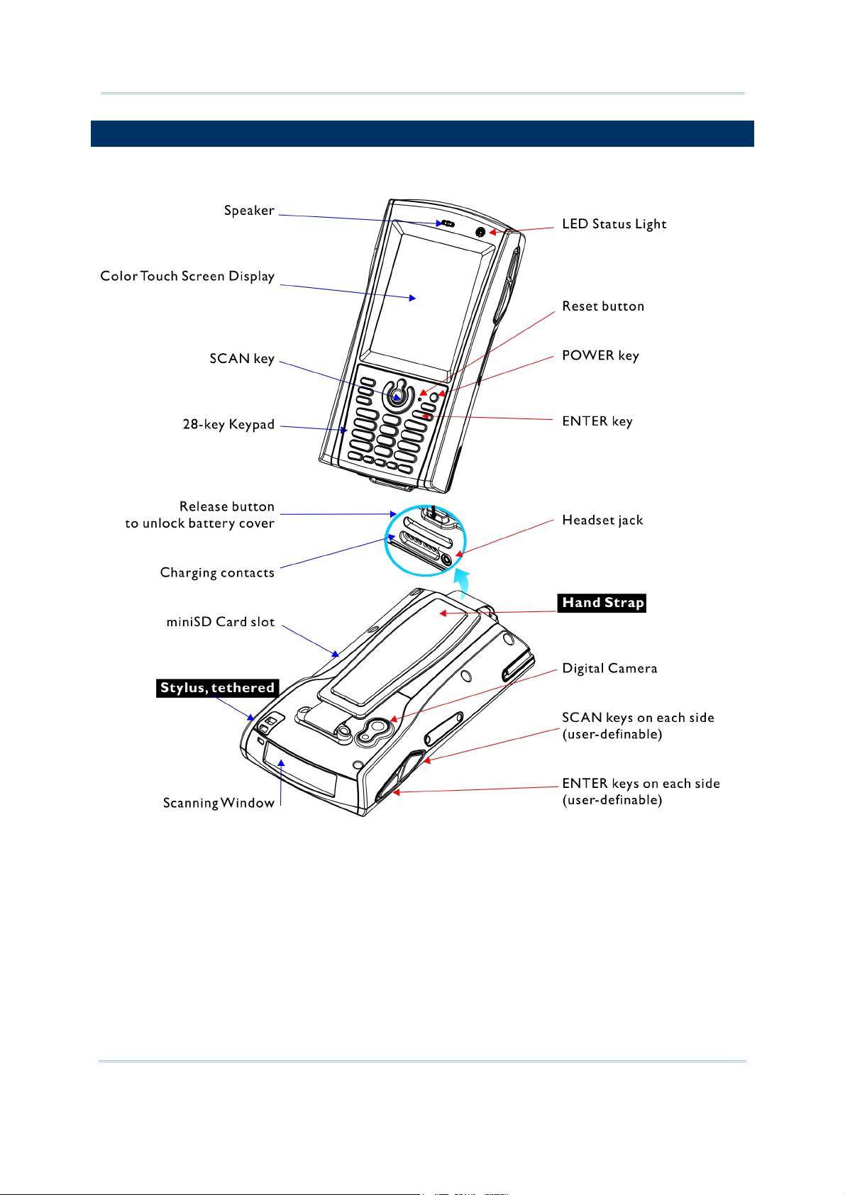
GETTING FAMILIARIZED WITH 9400CE
Figure 1: Front / Back View
2
Page 13
Introduction
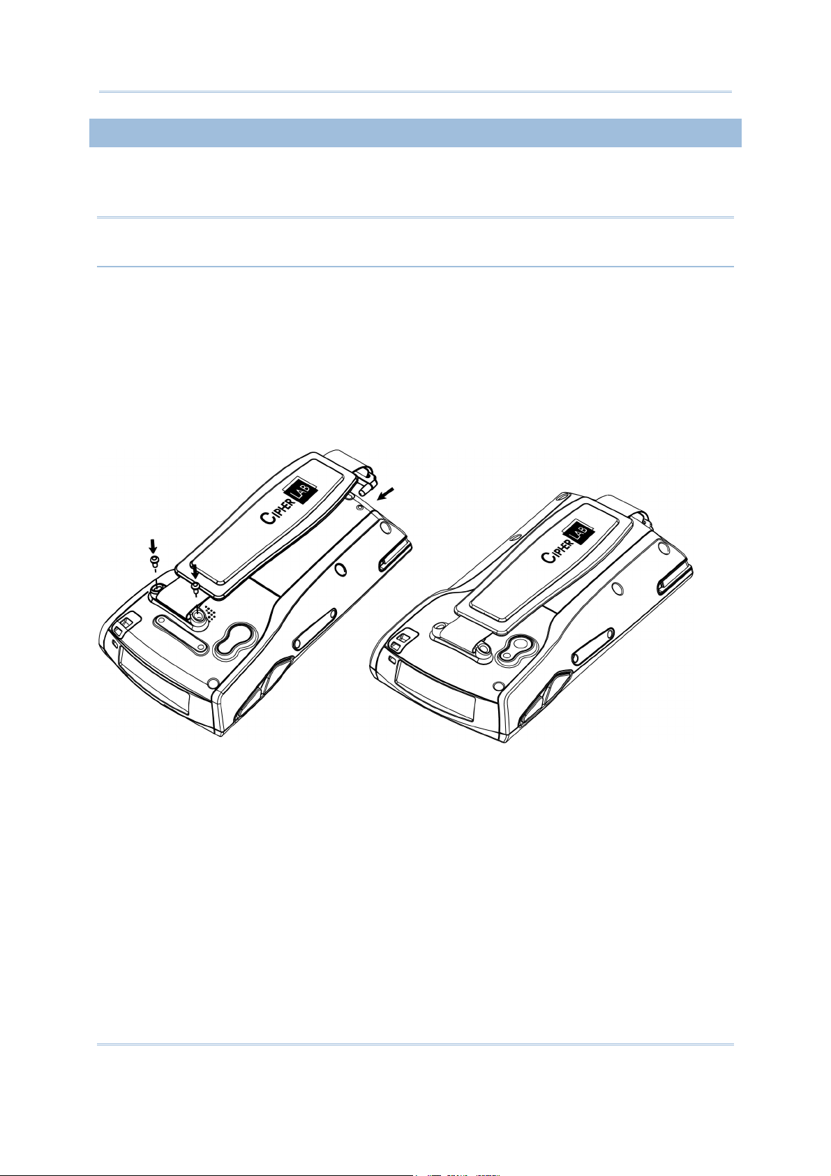
INSTALLING THE HAND STRAP
The hand strap is ideal for one-handed operation, which requires safe and convenient hold of the
mobile computer.
Warning: Always make sure the hand strap is well hooked and screwed to the back of the
mobile computer before use.
When the hand strap is desired, install it to the mobile computer by following these steps:
1) Place the mobile computer face down on a flat and clean surface.
2) Screw one end of the hand strap to the back of the mobile computer.
3) Insert and hook the other end of the hand strap to the bottom of the mobile computer.
4) Make sure the hand strap is securely attached to the mobile computer.
5) Adjust the length of the hand strap to suit your handbreadth.
Figure 2: Installing the
Hand Strap
3
Page 14

9400CE Mobile Computer Reference Manual
INSTALLING THE PISTOL GRIP
This contoured pistol grip enables intuitive trigger-and-scan operation, which is very helpful in scan
intensive applications.
When a pistol grip is necessary, install it to the mobile computer by following these steps:
1) Press
for the mobile computer to enter suspend mode.
2) Place the mobile computer face down on a flat and clean surface.
3) Remove the hand strap as well as the side plates as shown below.
4) Screw the pistol grip to the back of the mobile computer.
5) Make sure all screws are tightened up.
6) Turn on the mobile computer to test the trigger.
Figure 3: Installing the
Pistol Grip
4
Page 15
Introduction
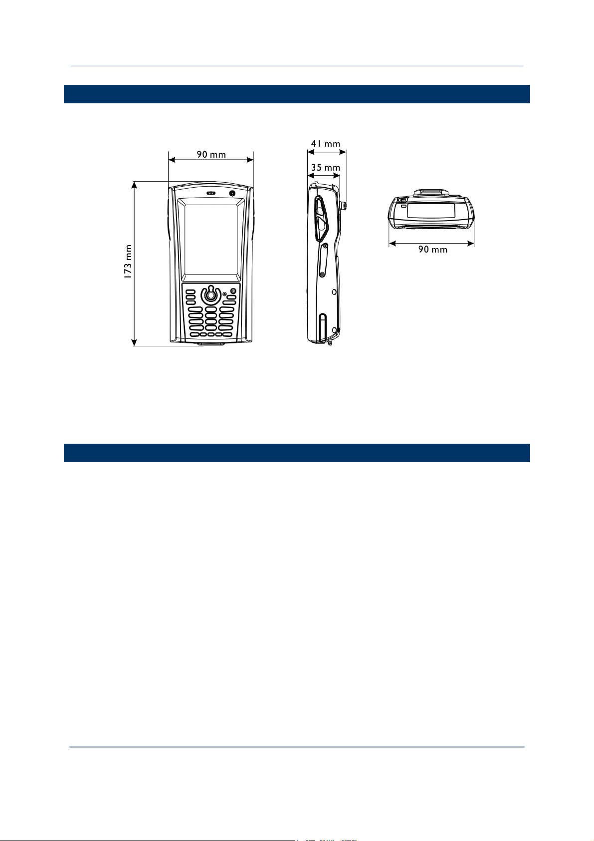
DIMENSIONS
Figure 4: Dimensions
FEATURES
Ergonomic design - ruggedized yet streamlined, with hand strap for secure hold.
Built tough to survive drop test and sealed against moisture/dust to industrial standard IP 64.
Microsoft Windows CE 5.0 operating system, 520 MHz Intel PXA270 processor
128 MB non-volatile NAND flash memory to store OS and software programs
(part of the free space is used as a storage card called DiskOnChip)
64 MB / 128 MB SDRAM to store and run programs, as well as store program data
One miniSD expansion slot for memory card
Dual mode support - One scan engine (integrated barcode scanner/imager) plus one RFID reader
Ambidextrous side triggers
Total wireless solution - connectivity includes Bluetooth, 802.11b/g and GSM/EDGE/GPRS.
A 3.5" color transflective TFT display delivers excellent visibility in all lighting conditions.
Programmable feedback includes speaker and vibrator.
Built-in power tools include Reader Configuration Utility, Backup Utility, etc.
Terminal Emulation client for VT100/220 and IBM 5250 enables a quick link to any backend
database.
5
Page 16

9400CE Mobile Computer Reference Manual
Application Generator (AG*.exe for desktop PC) enables easy customization of data collection
applications.
Programming support includes Reader DLL and System API.
Accessories and peripherals include pistol grip, international AC charging cradle, etc.
INSIDE THE PACKAGE
The following items are included in the package. Save the box and packaging material for future use in
case you need to store or ship the mobile computer.
9400CE Mobile Computer
Rechargeable Li-ion battery pack
Stylus
Hand Strap
Software & Manual CD
Note: For battery charging, you will need to purchase a charging cradle separately.
ACCESSORIES
Rich choices of optional accessories are available for you to enhance the total performance of the
mobile computer.
Pistol Grip (detachable)
Belt Holster
Protective Cover
miniSD Memory Card
Spare rechargeable Li-ion battery, standard or high capacity pack
4-slot Battery Charger
Charging & Communication Cradle
Vehicle Cradle
6
Page 17

USING THE 9400CE MOBILE COMPUTER
This chapter explains the features and usage of the 9400CE Mobile Computer.
IN THIS CHAPTER
1.1 Battery ................................................................................................................7
1.2 Memory ........................................................................................................... 11
1.3 Keypad ............................................................................................................. 13
1.4 Touch Screen ................................................................................................. 15
1.5 Notifications ................................................................................................... 17
1.6 Data Capture.................................................................................................. 18
1.7 Communications............................................................................................ 19
1.1 BATTERY
Chapter 1
Main Battery
The 9400CE Mobile Computer is powered by a rechargeable 3.7 V/1800 mAh Li-ion battery
pack, and it takes approximately 4 hours to fully charge it. However, the charging time may vary
by working condition. During normal operation, the mobile computer can work for up to 10
hours.
Backup Battery
The backup battery on the main board takes charge when the main battery is removed or
drained out. When fully charged, the 3.7 V/70 mAh rechargeable Lithium button cell helps retain
data in SRAM and maintain the system running in suspend mode for at least 20 hours without the
main battery. In the meantime, you have to replace the main battery as soon as possible.
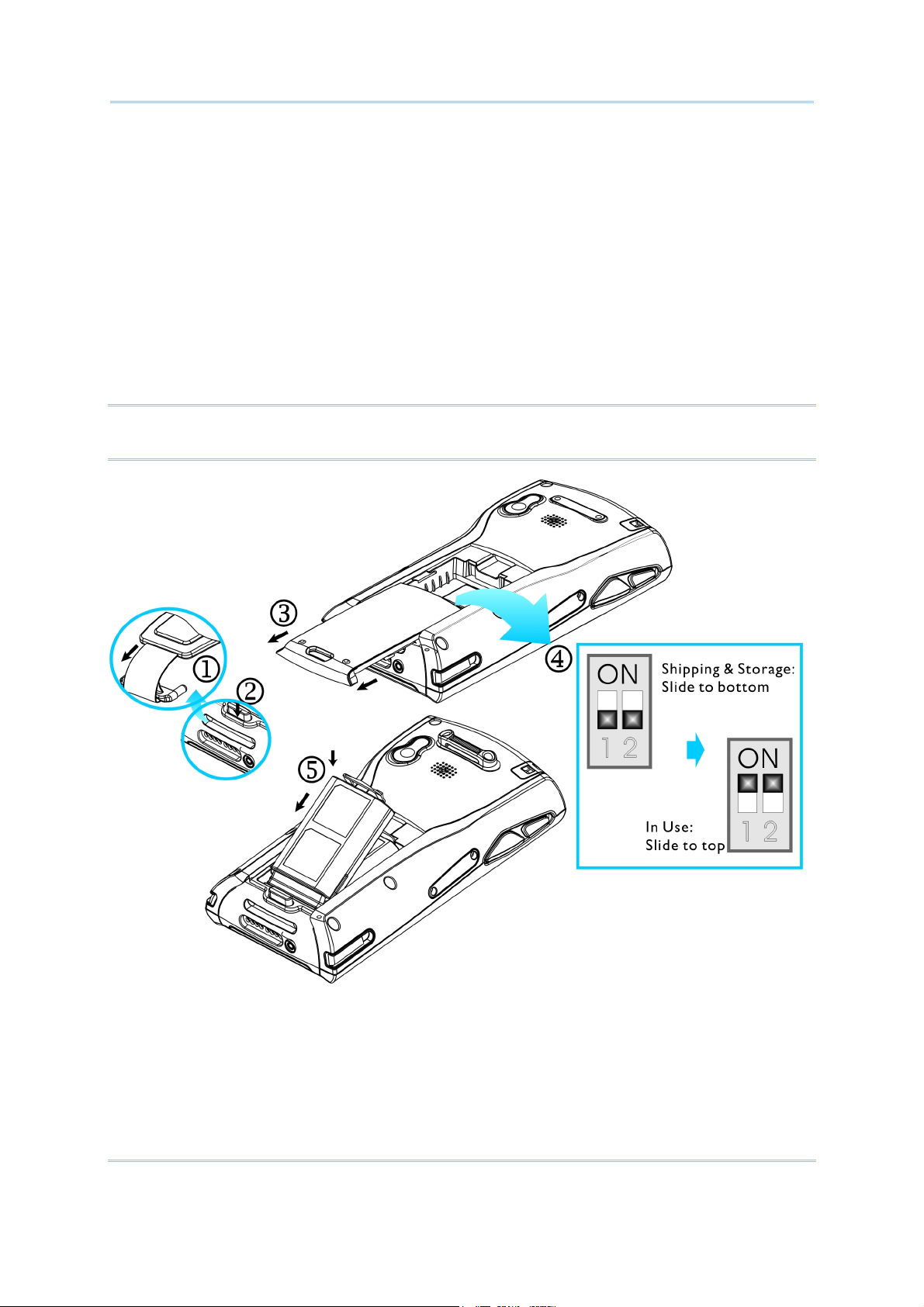
1.1.1 INSERTING THE BATTERY
When you first receive the package, the rechargeable functionality of the backup battery is turned
off. It is controlled by a DIP switch inside the battery compartment as shown below.
For shipping and storage purposes, save the mobile computer and the main battery in separate
packages, and adjust the DIP switch to the OFF position (bottom). This will keep both batteries in
good condition for future use.
Note: Any improper handling may reduce the battery life.
1) Press for the mobile computer to enter suspend mode.
2) Remove the hand strap.
7
Page 18
9400CE Mobile Computer Reference Manual
3) Hold the mobile computer still and press the release button to unlock the battery cover.
4) Slide off the battery cover.
5) Use the stylus (or a sharp-pointed object, such as a pencil) to adjust the DIP switch to the ON
position (top). Now the internal backup battery can be charged by the main battery.
6) Insert the battery pack into the battery compartment at a proper angle (30°~45°) so that the
metal contacts on the battery are met with the charging contacts inside the compartment. Make
sure that the battery is snugly fit into the compartment.
7) Slide the battery cover back onto the mobile computer until it clicks into place.
8) If the battery is charged, the mobile computer turns on.
If the mobile computer does not turn on, charge the battery.
Note: For a new battery, make sure it is fully charged before use. Always prepare a spare battery
pack, especially when you are on the road.
Figure 5: Installing the
Main Battery
8
Page 19

Chapter 1 Using the 9400CE Mobile Computer
1.1.2 CHARGING THE BATTERY
The main and backup batteries may not be charged to full for shipment. When you first receive the
package, you will need to charge batteries to full before using the mobile computer.
Note: To charge the batteries to full, it requires approximately 8 hours for the first time. After the
initial charging, it takes only 4 hours to charge the batteries to full.
Because the internal backup battery is constantly charged from the main battery, the initial charging
requires inserting the battery pack to the mobile computer and then seating the mobile computer in
the cradle for charging. This will have both the main and backup batteries charged at the same time.
To charge the backup battery, make sure that you slide the DIP switch inside the battery
compartment to the ON position.
Note: For a new battery, make sure it is fully charged before use. Always prepare a spare battery
pack, especially when you are on the road.
1.1.3 UNDERSTANDING THE BATTERY ICONS
The battery pack is the only power source for the mobile computer to work. It also charges the
backup battery on the main board so that the data stored in SRAM can be retained properly.
Therefore, when the main battery charge goes low (see below for battery status icon), you need to
replace the battery pack with a charged one or charge it as soon as possible. Most of all, always save
data before it is too late; you should backup important data on a regular basis.
BATTERY STATUS ICONS DESCRIPTION
Main Battery
Main battery charge becomes low.
Main battery charge becomes very low.
Charging Main battery is ready for charging.
Warning: Data loss may occur with SRAM during low battery condition. Always save data
before running out of power or keep a fresh battery for replacement.
1.1.4 POWER MANAGEMENT
For any portable device, power management is a critical issue especially when you are on the road.
Below are some tips to help you save battery power.
To speed up charging the mobile computer, turn off the mobile computer and seat it in the
cradle.
Bring a second battery pack on the road.
9
Page 20
9400CE Mobile Computer Reference Manual
Stop wireless connectivity, Bluetooth, 802.11b/g or GSM/GPRS that is not in use. Refer to the
Wireless Power Manager.
To save power, go to Start > Settings > Control Panel and select Display (for backlight
settings) or select Power (for power schemes).
Warning: Using backlight, wireless connectivity, and peripherals while on battery power will
substantially reduce battery life.
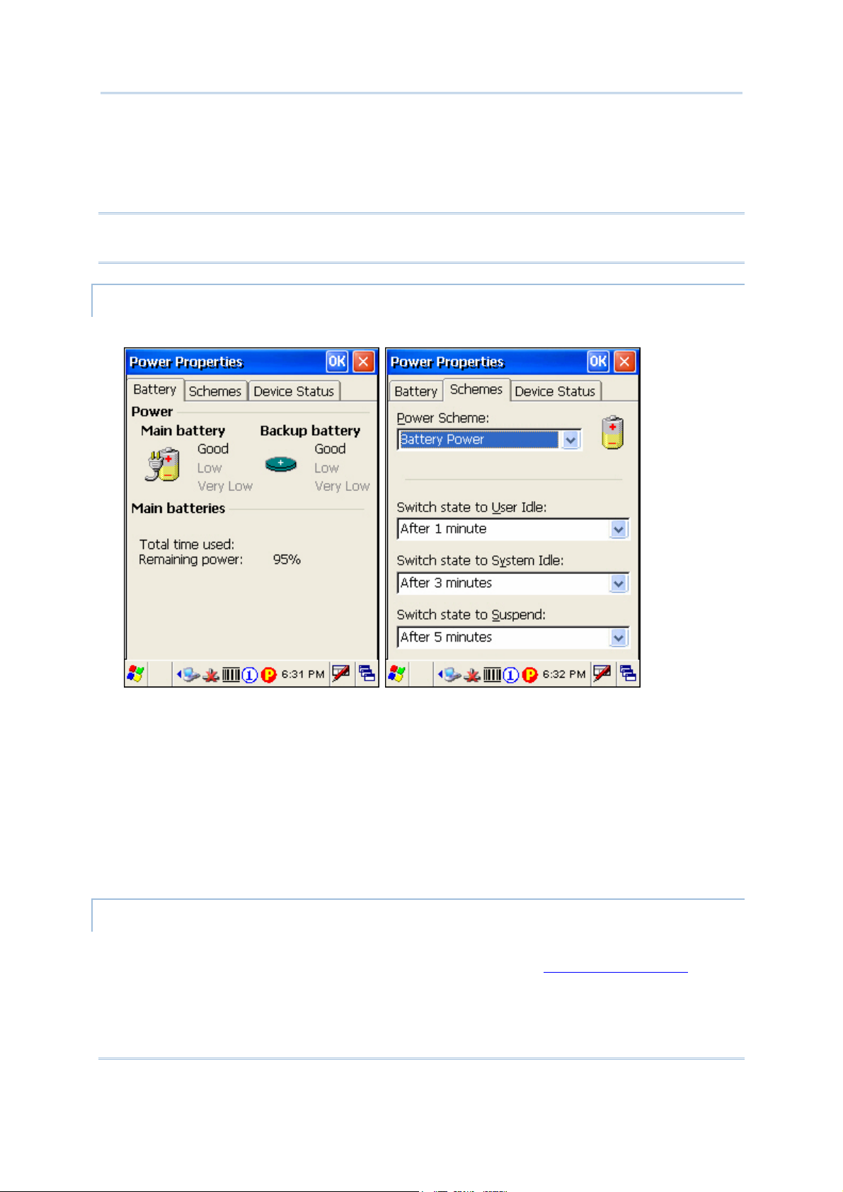
START > SETTINGS > CONTROL PANEL AND DOUBLE-TAP THE POWER ICON
1) In the Battery tab (left below), you can always monitor the charging status.
2) Tap the Schemes tab (right above).
3) Select the desired power scheme and options for suspending operation when not in use. The
system can be set to three different states to conserve power:
User Idle state
System Idle state
Suspend state
The time choices represent the amount of time that must pass before the system will switch to
the next power conservation state.
START > SETTINGS > CONTROL PANEL AND DOUBLE-TAP THE DISPLAY ICON
To conserve more power, you may go to Start > Settings > Control Panel and double-tap the
Display icon to configure the backlight setting. Refer to section 1.4.1
Adjusting the Backlight.
10
Page 21

Chapter 1 Using the 9400CE Mobile Computer
1.2 MEMORY
Read-only Memory (ROM)
128 megabytes flash memory for storing OS (Windows CE 5.0) and custom application programs.
Yet a small portion of the memory is referred to as DiskOnChip, which can store data and
programs that you wish to retain even after a hardware reset.
Random-access Memory (RAM)
64 or 128 megabytes SDRAM for storing and running programs, as well as storing program data.
Its contents will be retained by the backup battery.
Expansion Slot
The mobile computer is equipped with one miniSD card slot, which is user accessible. You may
upgrade memory by inserting an optional miniSD memory card.
1.2.1 CAUTION OF DATA LOSS
When the main battery is removed or drained, the backup battery on the main board is to retain the
contents of SRAM and maintain the OS in suspend mode for at least 20 hours, on condition that the
backup battery has already been fully charged.
If you want to put away the mobile computer for a couple of days, you should be aware that data
loss occurs when both the main and backup batteries discharge completely. Therefore, it is necessary
to backup data and files before putting away the mobile computer!
1.2.2 CHECKING THE STORAGE SPACE
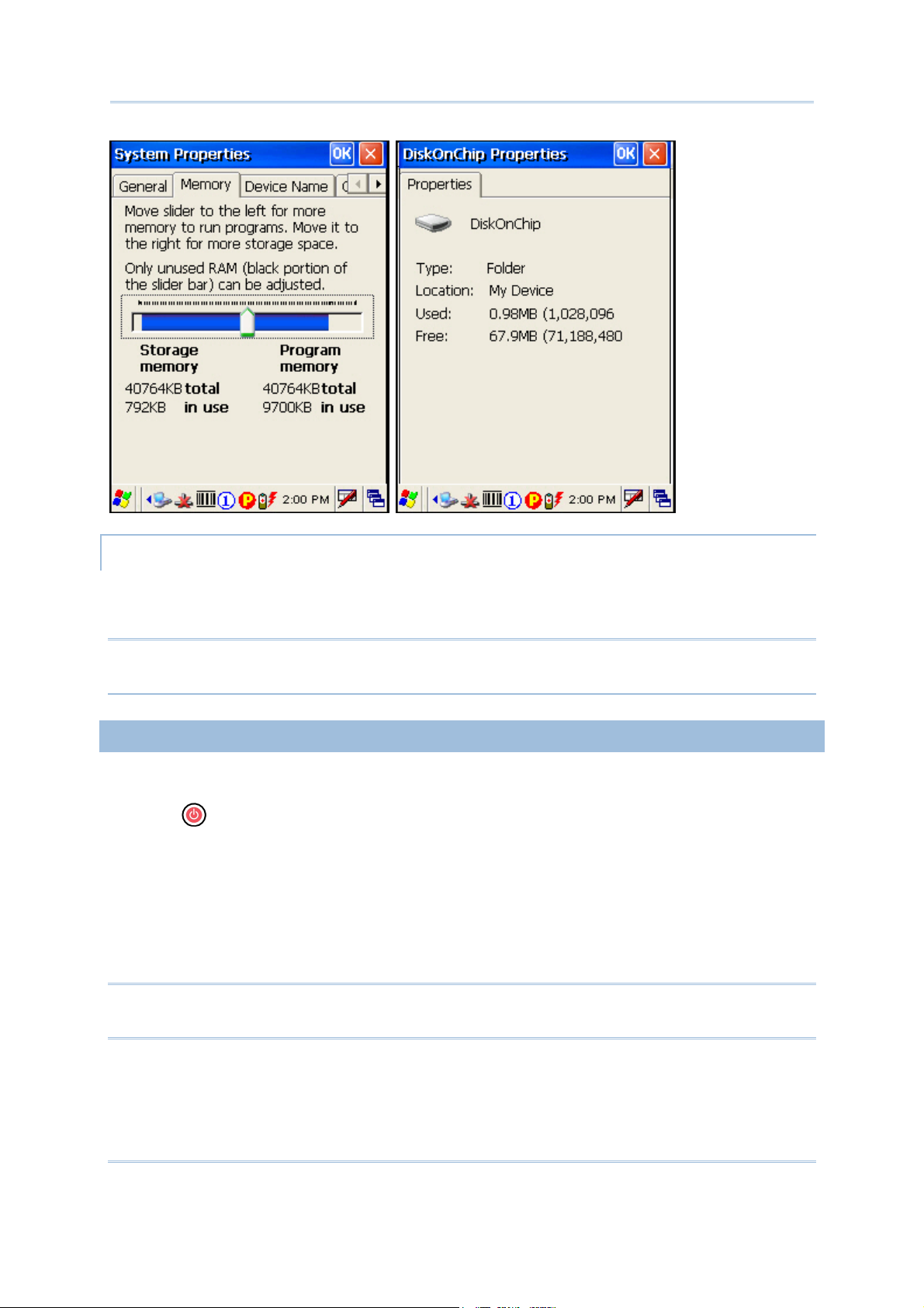
START > SETTINGS > CONTROL PANEL AND DOUBLE-TAP THE SYSTEM ICON
1) In the Memory tab (left below), it displays the current capacity and usage of the onboard
SDRAM, 64 MB / 128 MB.
2) You may tap, hold, and drag the slider to re-allocate the memory.
SDRAM STORAGE MEMORY (LEFT) PROGRAM MEMORY (RIGHT)
64 MB / 128 MB
onboard
(DESKTOP) MY DEVICE > DISKONCHIP
The DiskOnChip is part of the onboard 128 MB flash memory. Because the flash memory is
non-volatile, data or programs stored in DiskOnChip will not be erased after a hardware reset.
It refers to the memory allocated
for file and data storage.
It refers to the memory allocated
for running programs.
Tap and hold the DiskOnChip icon to select Properties from the pop-up menu. In the Properties tab
(right below), it displays the current capacity and usage of DiskOnChip.
11
Page 22
9400CE Mobile Computer Reference Manual
START > SETTINGS > CONTROL PANEL AND DOUBLE-TAP THE STORAGE MANAGER ICON
Here provides a tool for administrators to reformat the DiskOnChip folder or storage card
(miniSD).
Warning: This tool is for the use of system administrators only. Everything on the storage
device will be permanently erased after reformatting.
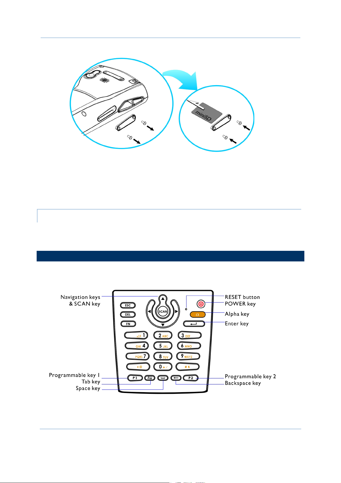
1.2.3 INSERTING THE MINISD CARD
If you wish to expand memory, follow these steps to insert a memory card into the miniSD card slot:
1) Press
2) Place the mobile computer face down on a flat and clean surface.
3) Remove the side plate by unscrewing the two screws (on the right side when you place the
mobile computer face down) as shown below.
4) Insert the miniSD card properly.
5) Replace the side plate and tighten the screws.
Warning: Make sure the mobile computer is set to Suspend mode; otherwise, it may cause
for the mobile computer to enter suspend mode.
damage to the mobile computer.
12
Page 23
Chapter 1 Using the 9400CE Mobile Computer
Figure 6: Inserting the
miniSD Card
REMOVING THE MINISD CARD
If you wish to remove the miniSD card, simply push the card after removing the side plate. The
miniSD card will be rejected automatically.
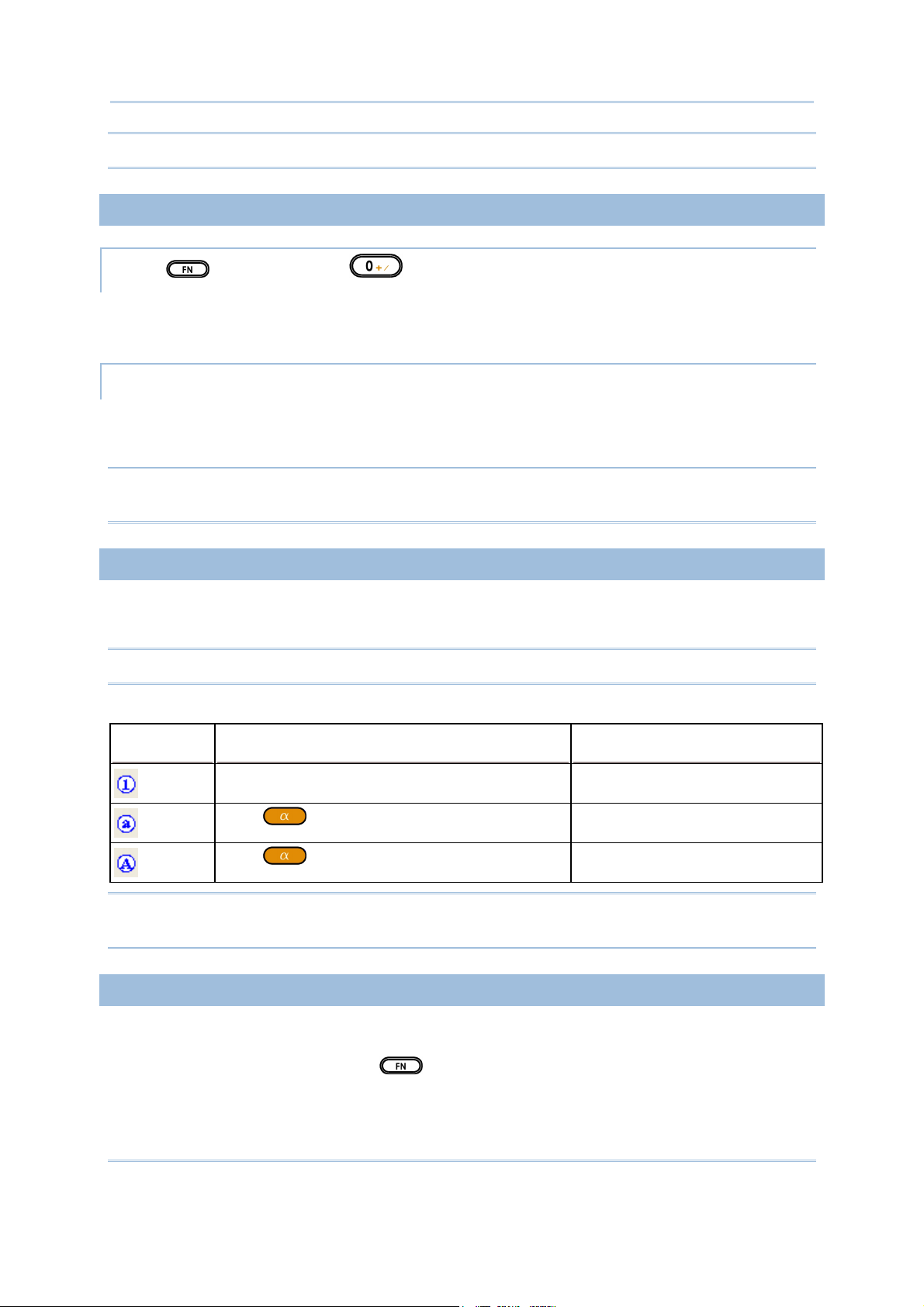
1.3 KEYPAD
Silicon rubber has been chosen for their durability and prompt feedback. The 28-key keypad includes
alphanumeric, navigation, function keys, and so on. This keypad is set to numeric mode by default.
Figure 7: 28-key Layout
13
Page 24
9400CE Mobile Computer Reference Manual
Note: Functionality of keys is application-dependent.
1.3.1 USING THE KEYPAD
PRESS FIRST, AND THEN
The LED backlight of keypad is turned off by default. It can be toggled ON/OFF by the key
combination: [Func] + [0].
START > SETTINGS > CONTROL PANEL AND DOUBLE-TAP THE KEYBOARD ICON
The Character Repeat functionality is enabled by default. You may cancel the check box to disable it.
When enabled, tap, hold, and drag the slider for a desired Repeat Delay and Repeat Rate.
Warning: It is suggested to turn on the keypad backlight while working in a dark area;
however, using backlight while on battery power will substantially reduce battery life.
1.3.2 ALPHA KEY
This alphanumeric keypad is set to numeric mode by default. The Alpha key serves as a toggle among
numeric, alpha (lower-case alphabetic), and ALPHA (upper-case alphabetic) input modes.
Note: It is not necessary to hold down the [Alpha] key.
The alpha icon will appear on the status bar in a sequence as shown below.
STATUS ICON ALPHA KEY INPUT MODE
N/A Numbers
Press
one time
Small letters
Press
two times
Capital letters
Note: If you are using the software keypad via SIP, tap CAP (Caps Lock) to toggle between upper
case and lower case alphabetic modes.
1.3.3 FUNCTION KEY
The [Func] (function) key serves as a modifier key.
1) To enable this modifier key, press
on the keypad.
14
Page 25
Chapter 1 Using the 9400CE Mobile Computer
A circular icon of the letter "F" will appear on the status bar. This modifier key is hold down as
long as the icon is displayed.
2) Now press another key to get the value of key combination (say, press [1] to get the value of
F1). The icon will go off now.
3) To get the value of another key combination modified by the [Func] key, repeat the above steps.
4) To abort the key modification, press
again, and the icon will go off.
Note: It is not necessary to hold down the [Func] key.
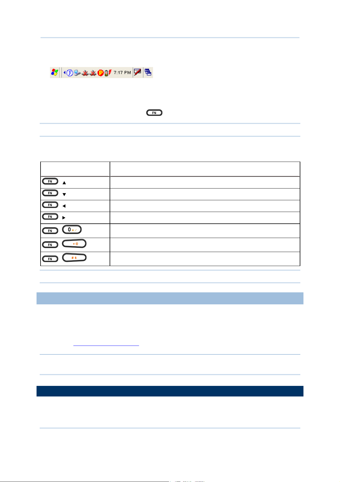
The functionality of each key combination is application-dependent. Below is a list of the factory
setting for a variety of key combinations.
KEY COMBINATION ACTION
,
,
,
,
,
,
,
PgUp (red-coded): move text up one screenful
PgDn (red-coded): move text down one screenful
Home (red-coded): move to the beginning of screen or document
End (red-coded): move to the end of screen or document
Toggle ON/OFF the backlight of keypad only
Turn ON the backlight of LCD and decrease its luminosity
Turn ON the backlight of LCD and increase its luminosity
Note: Press the [Func] key first, and then press the second key for a specific function.
1.3.4 PROGRAMMABLE KEYS
Two user-definable keys, named P1 and P2, are provided on the keypad. Together with the SCAN
key as well as the four side triggers on each side of the touch screen, they can be re-defined as
another key or to serve as a shortcut key for launching a specific program.
Refer to the
Button Assignment Utility.
Note: By default, the four side triggers are programmed to serve as ENTER keys (upper ones) as
well as SCAN keys (lower ones).
1.4 TOUCH SCREEN
The mobile computer comes with a 3.5" TFT graphic LCD, 320 by 240 pixels resolution (QVGA).
15
Page 26
9400CE Mobile Computer Reference Manual
The LED backlight of screen, which helps ease reading under dim environments, can be controlled
manually and automatically.
Warning: Using backlight while on battery power will substantially reduce battery life. It is
suggested to dim the backlight while working in a well-lit area or automatically turn
off the mobile computer when not in use.
1.4.1 ADJUSTING THE BACKLIGHT
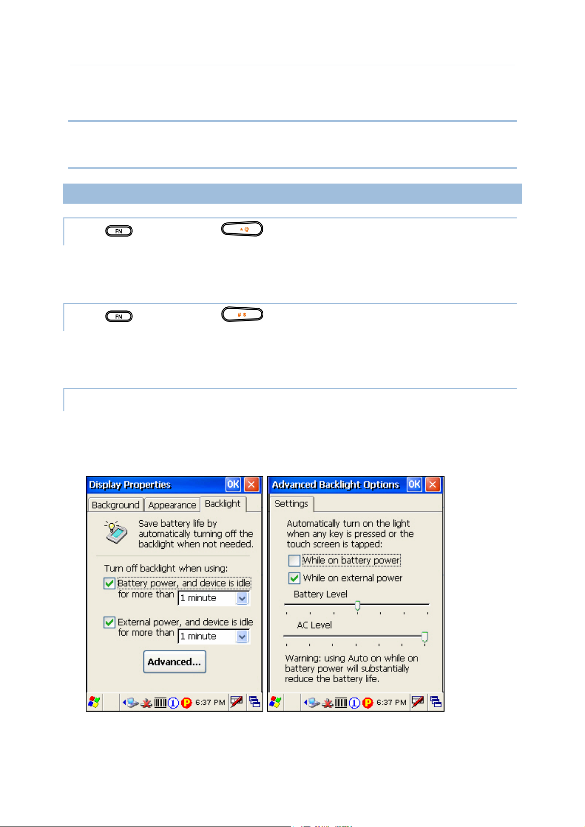
PRESS FIRST, AND THEN
The LED backlight of the screen can be turned on and adjusted decreasingly by the key combination:
[Func] + [-]. Keep pressing the key combination ([Func] first, and then [-]) until the luminosity is
decreased to a desired level.
PRESS
The LED backlight of the screen can be turned on and adjusted increasingly by the key combination:
[Func] + [.]. Keep pressing the key combination ([Func] first, and then [.]) until the luminosity is
increased to a desired level.
START > SETTINGS > CONTROL PANEL AND DOUBLE-TAP THE DISPLAY ICON
1) Tap the Backlight tab (left below).
2) Select one or both of the check boxes to automatically turn off the LCD backlight when using
batteries or external power. From the appropriate list, select the amount of time the device
should be idle before the backlight is turned off.
FIRST, AND THEN
16
Page 27
Chapter 1 Using the 9400CE Mobile Computer
3) Tap the [Advanced] button (right above).
4) In the Settings tab, you can select the luminosity of backlight when it is set to be automatically
turned on by pressing any key or tapping the screen. Tap, hold, and drag the slider for AC and
battery powered respectively. For more luminosity, move the slider to the right.
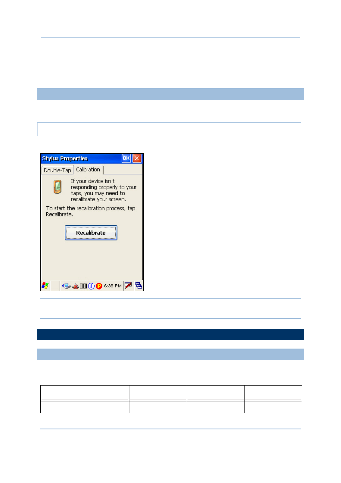
1.4.2 RE-CALIBRATING THE SCREEN
This LCD is also a touch screen that can be calibrated through screen alignment.
START > SETTINGS > CONTROL PANEL AND DOUBLE-TAP THE STYLUS ICON
Tap the Calibration tab, and then tap the [Recalibrate] button.
Warning: DO NOT use any pointed or sharp objects to move against the surface of the
screen.
1.5 NOTIFICATIONS
1.5.1 STATUS LED
The tri-color LED on top is used to provide information on the charging status or wireless power
status.
TASKS GREEN LED RED LED BLUE
Charging 9400CE --- On ---
17
Page 28

9400CE Mobile Computer Reference Manual
Charging done On --- ---
Good Read On --- ---
Bluetooth enabled --- --- On
Note: The green LED is also used for "Good Read" while collecting data.
1.5.2 AUDIO
Speaker
The mobile computer is integrated with a mono speaker, a low power transducer type, used for
playing sounds applied to events in Windows and programs, as well as playing audio files such as
.WAV files. In addition, it can be programmed for status feedback.
Headset
A headset jack is provided, which is a 2.5 mm DIA stereo earphone jack with microphone input.
Bluetooth headset is also supported.
1.5.3 VIBRATOR
The mobile computer is integrated with a vibrator, which is software programmable for feedback.
This can be helpful when working in noisy environments.
1.6 DATA CAPTURE
1.6.1 BARCODE & RFID READER
A wide variety of scan engines is available for delivering flexibility to meet different requirements.
Depending on the scan engine integrated (check the "Active Device" setting in ReaderConfig), the
mobile computer is capable of scanning barcodes of a number of symbologies that are enabled by
default. If you need to scan barcodes that are encoded in a different symbology, use the Reader
Configuration Utility to enable the symbology first.
Refer to Appendixes for details on scan engine settings.
Appendix I – Scan Engine Settings lists the symbologies and RFID tags supported.
Appendix II – CCD/Laser Scan Engine provides information on the reader settings as well as
symbology settings for the CCD or Laser scan engine.
Appendix III – 2D Scan Engine provides information on the reader settings as well as symbology
settings for the 2D scan engine.
Note: The mobile computer allows the co-existence of one integrated scan engine and the RFID
reader.
18
Page 29
Chapter 1 Using the 9400CE Mobile Computer
1.6.2 DIGITAL CAMERA
An integrated 2 mega-pixel CMOS camera inside the computer is specifically designed for collecting
image data. Refer to the Image Capture Utility.
1.7 COMMUNICATIONS
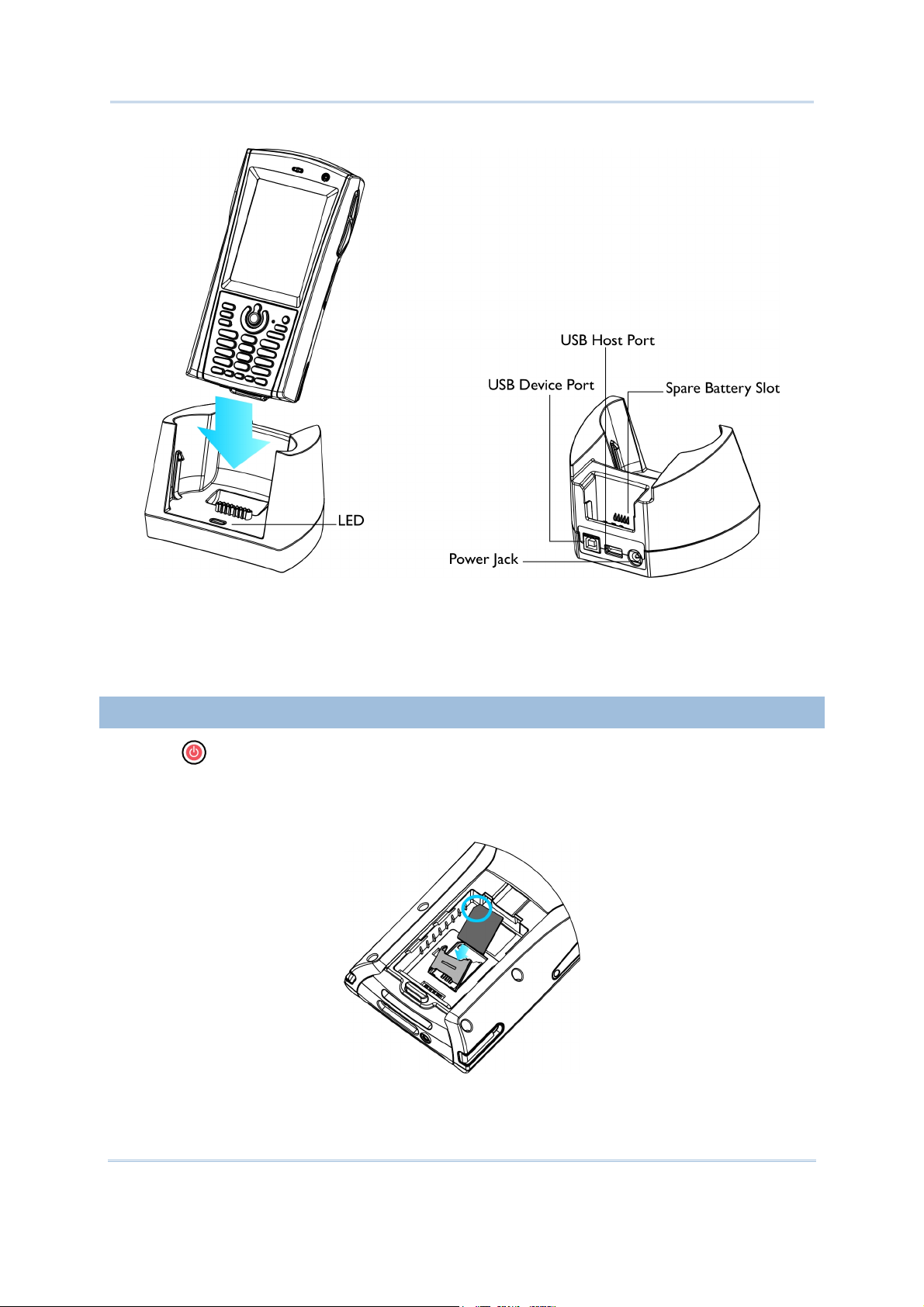
1.7.1 USING THE CRADLE
The cradle is designed for charging and communications at the same time.
1) Place the cradle on a flat and clean surface.
2) Connect the line of the power adaptor to the power jack on the back of the cradle.
3) Connect the power adaptor to a suitable power outlet.
4) The cradle is ready for charging.
5) Seat the mobile computer in the cradle.
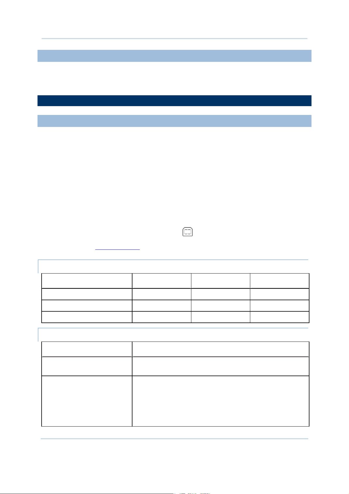
If data communications are desired at the same time, you can establish a proper connection with
a computer or remote host. For example, you may establish a USB connection for ActiveSync.
Make sure that you have Microsoft ActiveSync installed on your computer before you connect
the USB cable from the cradle's USB device port (
Refer to section 2.3
Using ActiveSync.
) to your computer.
UNDERSTANDING THE STATUS INDICATORS
TASKS GREEN LED RED LED BLUE
Power ON --- --- On
Charging Spare Battery --- On ---
Charging Done On --- ---
UNDERSTANDING THE COMMUNICATION PORTS
PORTS PURPOSE
USB Device Port This port is provided for connecting to your computer for
establishing a connection for ActiveSync.
USB Host Port This port is provided for connecting a USB device:
Keyboard
Mouse
Card reader
Storage device, such as a memory stick
19
Page 30
9400CE Mobile Computer Reference Manual
Figure 8: Understanding
the Cradle
1.7.2 INSERTING THE SIM CARD
1) Press for the mobile computer to enter suspend mode.
2) Hold the mobile computer still and remove the hand strap as well as the battery.
3) Use your finger to slide the locking plate towards its hinge to unlock the SIM card holder.
Figure 9: Inserting the SIM
Card
20
Page 31

Chapter 1 Using the 9400CE Mobile Computer
4) Flip up the SIM card holder.
5) Insert the SIM card to the SIM card holder, using the card orientation shown below.
6) Push the SIM card holder down.
7) Slide the locking plate away from its hinge to secure the SIM card holder.
1.7.3 TURN OFF THE WIRELESS NETWORKS
The mobile computer supports state-of-the-art wireless technologies, Bluetooth and 802.11b/g, so
that it is able to send/receive data in real time in an efficient way.
You may choose to have the GSM/GPRS module embedded for a total wireless solution for data and
voice communications.
Refer to the associated utilities.
1.7.4 USING THE HEADSET
Connect the headset to the headset jack (2.5 mm DIA) at the bottom of the mobile computer. You
can use the headset for audio playback or communication via Voice over IP (VoIP).
Bluetooth headset is supported, bringing you the freedom of cordless mobility.
21
Page 32

9400CE Mobile Computer Reference Manual
22
Page 33

Chapter 2
LEARNING WINDOWS CE BASICS
This chapter mainly describes the basic skills to work with the 9400CE Mobile Computer. The
add-on utilities for applications regarding data collection, processing, and transmission, are
introduced in the following chapters.
The 9400CE Mobile Computer is specifically designed for real-time data collection in the Windows
CE 5.0 environment. It won't take long for any Windows user to get familiarized with it. Keep these
basic skills in mind and explore this Windows CE device at ease.
Double-tap an item to select it.
Tap and hold an item to see a menu that enables tasks, such as cut, copy, rename, delete, etc.
Tap and drag to select multiple items.
Tap or on the toolbar to close an active window, a dialog box, or a running
application.
If the button is not displayed, press
on the physical keypad.
Tap on the toolbar to save the current settings and exit the application (or minimize the
window in some applications).
If the button is not displayed, press
on the physical keypad.
IN THIS CHAPTER
2.1 Getting Started .............................................................................................. 23
2.2 Finding out the Capabilities of Your Mobile Computer ...................... 28
2.3 Using ActiveSync ........................................................................................... 29
2.4 Managing Programs ....................................................................................... 31
2.5 System Reset & Auto Run........................................................................... 35
2.6 Updating OS Image ....................................................................................... 36
2.1 GETTING STARTED
When the 9400CE Mobile Computer is fully charged, you may remove it from the cradle. Then,
press
are using the mobile computer for the first time, there are a couple of things to do after the desktop
comes up.
to turn on the mobile computer and wait for the Windows CE desktop to come up. If you
To select your time zone and set the local time: Start > Settings > Control Panel and select
Date/Time.
To align the touch screen: Start > Settings > Control Panel and select Stylus.
23
Page 34

9400CE Mobile Computer Reference Manual
SUSPEND MODE
Like your PDA, Pocket PC and most handheld devices, the 9400CE Mobile Computer functions
when it is turned on. This is because the Windows CE operating system eliminates the booting
process and runs continuously.
Turn On (= Resume from Suspend)
To turn on the mobile computer, simply press
.
Turn Off (= Suspend)
To turn off the mobile computer, press
The system is now ready for use but not in use. This is referred to as Suspend mode or Standby
mode. It means the system is in power-saving status and waiting for user interference.
Warning: To save battery power, it is suggested that the mobile computer is set to be
automatically turned off when not in use. Refer to section 1.1.4 Power Management
for more information about saving power.
again, or select Suspend from the Start Menu.
2.1.1 DESKTOP
The desktop appears when the mobile computer is turned on (left below). Tap and hold anywhere
blank on the screen to manage or configure the desktop (right below).
Alternatively, you may tap
to the right of the taskbar, and then select Desktop.
24
Page 35

Chapter 2 Learning Windows CE Basics
Note: To customize the desktop, tap anywhere blank on the desktop and select Properties.
When you turn on the mobile computer and seat it in the cradle for the first time, you will find these
icons displayed on the taskbar. Refer to section 2.1.2
ICON DESCRIPTION SEE ALSO
Taskbar for more information on the icons.
This icon shows that your cradle is directly connected to a computer
via USB port.
Make sure you have Microsoft ActiveSync installed on your
1.7.1 Using the
Cradle
2.3 Using ActiveSync
computer.
This icon shows that BTPAN1 is disabled.
This icon is a shortcut to the Wireless Power Manager that controls
the power to GSM/GPRS and 802.11b/g modules.
This icon shows that the main battery is ready for charging. For
information on charging status, refer to the LEDs on the mobile
3.1 Changing System
Settings
4.1 Wireless Power
Manager
1.1.3 Understanding
the Battery Icons
computer as well as on the cradle.
This icon shows that numeric mode is in use for data input via keypad. 1.3.4 Alpha Key
2.1.2 TASKBAR
The taskbar is at the bottom of the screen for displaying the Start button, status icons for various
connections or programs, SIP button, Switch Task button, etc.
Note: To configure different connections, go to Start > Settings and select Network and
Dial-up Connections.
25
Page 36

9400CE Mobile Computer Reference Manual
UNDERSTANDING THE ICONS ON THE TASKBAR
ICON DESCRIPTION SEE ALSO
The USB connection for ActiveSync operation is successfully
established.
Double-tap it to view status. Tap [Disconnect] if necessary.
The Bluetooth PAN connection fails. (= disconnected)
The Bluetooth PAN connection is successfully established through the
Bluetooth Manager utility.
Double-tap it to view or renew IP Information.
It provides control of the power to the 802.11b/g and GSM/GPRS
modules.
Double-tap any of these icons to configure the power setting.
It indicates the GPRS module is enabled.
See GPRS status icon below.
It indicates the Wi-Fi module (802.11b/g) is enabled.
See WLAN1 status icons below.
The GPRS connection has been opened. If it fails, the icon will be gone.
If the icon persists, it means the GPRS connection is successfully
established.
3.2.1 USB
Connection (via
cradle)
3.2.4 BTPAN
4.1 Wireless Power
Manager
3.2.2 GPRS
Double-tap it to view status. Tap [Disconnect] if necessary.
The Wi-Fi connection fails. (= disconnected)
Double-tap it to access the Wireless Information tab for
establishing a new connection.
The Wi-Fi connection is successfully established.
3.2.3 WLAN
Double-tap it to view or renew IP & Wireless Information.
It provides access to the Bluetooth services.
Initially, you need to go to Start > Programs > BTManager to open
the Bluetooth Manager so that this icon will appear on the taskbar.
It provides access to the Reader Configuration Utility.
4.2 Bluetooth
Manager
Initially, you need to double -tap the ReaderConfig shortcut on the
desktop so that this icon will appear on the taskbar.
Tap it to change the input method. Software Input
Tap it to switch to desktop or any task, such as a running program or
window.
Panel (SIP)
Switch Task
26
Page 37

Chapter 2 Learning Windows CE Basics
It indicates the battery status. The other icons are
It indicates the current input mode of keypad. The other icons are
.
.
It indicates the modifier key is enabled. (= function mode) 1.3.5 Function Key
2.1.3 START MENU
Tap the Start button on the taskbar to open the Start Menu.
1.1.3 Understanding
the Battery icons
1.3.4 Alpha Key
OPTIONS DESCRIPTION
Programs Provides access to available programs in the directory: \Windows\Programs
Favorites Provides access to your favorites in the directory: \Windows\Favorites
Documents Provides access to recent opened documents in the directory: \Windows\Recent
Settings Provides access to
Control Panel
Network and Dial-up Connections
Taskbar and Start Menu
Run... Runs a program or application.
Suspend Enters the Suspend mode.
Note: To configure the Start menu and taskbar, go to Start > Settings and select Taskbar and
Start Menu.
2.1.4 INPUT METHODS
Data entry can be performed by the following methods:
Type with the physical keypad.
Scan barcode or RFID tag in applications, e.g. WordPad, CipherLab's Application Generator, etc.
Tap or write using SIP (Soft Input Panel)
27
Page 38

9400CE Mobile Computer Reference Manual
USING THE SOFT INPUT PANEL (SIP)
Tap the SIP button on the taskbar to select a SIP mode or hide the input panel.
In each mode, the characters appear as typed text on the screen.
OPTIONS DESCRIPTION
Keyboard To type using the virtual keyboard.
Transcriber To write freely on the screen in applications, such as WordPad, Inbox, etc.
2.2 FINDING OUT THE CAPABILITIES OF YOUR MOBILE COMPUTER
1) Go to Start > Settings > Control Panel and select System to obtain essential system
information.
2) Select the Device Name tab to change the identification for the mobile computer.
DEVICE CONFIGURATION CODE
The device configuration of the 9400CE Mobile Computer is displayed in 5 digits: xxxx-x
Take the screenshot of System Properties below for example. Its device configuration is “2410-0”,
which means the 28-key mobile computer has equipped with the following parts:
A scan engine that employs Laser scan engine
Integrated Bluetooth and Wi-Fi modules
An RFID reader
DEVICE CODE
MODULAR COMPONENT
1st digit Reader module 0= none
TYPES
1= CCD scan engine
2= Laser scan engine
3= 2D scan engine
2nd digit Wireless module 3= Bluetooth + GSM/GPRS
4= Bluetooth + 802.11b/g
5= Bluetooth only
7= Bluetooth + GSM/GPRS + 802.11b/g
28
Page 39

Chapter 2 Learning Windows CE Basics
3rd digit RFID module 0= none
1= RFID reader
4th digit Reserved ---
5th digit Keypad module 0= 28-key
2.3 USING ACTIVESYNC
ActiveSync is used to synchronize information between the 9400CE Mobile Computer and your
desktop computer, to install programs on the mobile computer, and to backup and restore the
mobile computer.
The Microsoft ActiveSync program has to be installed on your desktop computer first.
To download the up-to-date version of the program, you may need to go to Microsoft's official
web site for Windows Mobile devices as shown below.
http://www.microsoft.com/windowsmobile/default.mspx
After downloading and installation, run the program. For detailed information on the program,
you may click the Help menu, and then select the Microsoft ActiveSync Help.
2.3.1 SYNCHRONIZATION WITH YOUR COMPUTER
1) Follow these instructions for initial ActiveSync operation:
Connect the USB cable from the cradle's USB device port ( ) to your computer.
Connect the power cable from the cradle to a nearby power outlet.
Turn on the mobile computer and seat it in the cradle.
29
Page 40

9400CE Mobile Computer Reference Manual
2) Your computer will automatically detect the USB device. Click [OK] when the connection is
established.
3) Select which partnership to set up. If you want to synchronize data between the mobile
computer and your personal computer, select Standard Partnership; otherwise, select Guest
Partnership.
4) Wait a few seconds for the mobile computer to get connected (and synchronized if a Standard
Partnership is selected).
Note: (1) For ActiveSync via Bluetooth, refer to the Bluetooth Manager.
(2) We recommend that you have ActiveSync 3.7.1 installed on your computer because
ActiveSync 4.x does not officially support Windows CE 5.0 devices.
2.3.2 ADD/REMOVE PROGRAMS
Click [Add/Remove Programs] from the Tools Menu so that you can proceed to install a program
that is designed to be used on a mobile device running Windows CE.
If a user program is no longer desired, you may remove it from the system. Click [Add/Remove
Programs] from the Tools Menu so that you can proceed to un-install a program that is designed to
be used on a mobile device running Windows CE.
ALTERNATIVE TO INSTALL NEW PROGRAMS (COPY & PASTE)
Alternatively, you may install a new program manually.
1) When connected, open the Microsoft ActiveSync window on your desktop computer.
2) Click the Explorer button from the toolbar.
3) Navigate to the target folder, e.g. the Programs folder, depending on where you wish to access
the program.
4) Navigate through file folders on your computer to find the new program (.CAB, .EXE, etc.)
5) Right-click the program and select [copy] from the pop-up menu.
6) Back to the target folder in step 3.
Right-click anywhere blank and select [Paste] from the pop-up menu.
30
Page 41

Chapter 2 Learning Windows CE Basics
7) On the mobile computer, go to Start > Programs and the new program will appear.
ALTERNATIVE TO REMOVE PROGRAMS (CONTROL PANEL)
Alternatively, you may un-install a new program manually.
1) Go to Start > Settings > Control Panel and select Remove Programs.
2) Tap the name of the program that you want to delete.
3) Tap [Remove].
4) Tap [Yes] to un-install the program.
Note: If the program does not appear in the list of installed programs, you may use Windows
Explorer to locate it. Tap and hold the program to select [Delete] from the pop-up menu.
2.3.3 BACKUP/RESTORE
To best protect your work, you should regularly back up information on your mobile computer. You
can perform a backup by during the ActiveSync operation. The backup file is stored on your desktop
computer.
2.4 MANAGING PROGRAMS
2.4.1 QUICK LAUNCH A PROGRAM
Tap the Start button to view the Start Menu. To quick launch a program, tap it from the Programs
folder.
Note: Alternatively, you may tap Start and select Run to run a specific program or open a
document.
31
Page 42

9400CE Mobile Computer Reference Manual
If you wish to quick launch a new program, add it to the Programs folder: My
Device\Windows\Programs. The program will become available in the Start Menu. To add a
new program or subfolder to the Programs folder, you can either use Windows Explorer or
ActiveSync.
Windows Explorer: to move the program by [Copy] and [Paste Shortcut].
ActiveSync on the desktop computer: to create a shortcut to the program, and place the
shortcut in the Programs folder.
Warning: To avoid making any changes to the program configurations by accident, we
recommend you to use [Copy] and [Paste Shortcut] rather than [Cut] and [Paste].
USING WINDOWS EXPLORER TO ADD A PROGRAM TO START MENU
1) Go to Start > Programs and select Windows Explorer.
2) Navigate through file folders to find the program you desire.
3) Tap and hold the program to select [Copy] from the pop-up menu (left below).
4) Navigate to the Programs folder – My Device\Windows\Programs (right above).
32
Page 43

Chapter 2 Learning Windows CE Basics
5) Tap and hold anywhere blank on the screen to select [Paste Shortcut] from the pop-up menu.
The new program will be added to the Programs folder.
6) Go to Start > Programs and the new program will appear now.
USING ACTIVESYNC TO ADD A PROGRAM TO START MENU
1) When connected, open the Microsoft ActiveSync window on your desktop computer.
2) Click the Explorer button from the toolbar.
3) Navigate through file folders to find the program you desire.
4) Right-click the program and select [Create Shortcut] from the pop-up menu.
33
Page 44

9400CE Mobile Computer Reference Manual
5) Right-click the shortcut and select [Cut] from the pop-up menu.
6) Navigate to the Programs folder – My Device\Windows\Programs.
7) Right-click anywhere blank on the window and select [Paste] from the pop-up menu. The new
program will be added to the Programs folder.
8) On the mobile computer, go to Start > Programs and the new program will appear now.
Note: [Create Shortcut], [Cut], and [Paste]: The same result can be performed by [Copy] and
[Paste Shortcut].
2.4.2 CREATE A FOLDER
USING WINDOWS EXPLORER TO ADD A NEW FOLDER
1) Go to Start > Programs and select Windows Explorer.
2) Navigate through file folders to find where you wish to create a new folder.
3) Right-click anywhere blank on the window and select [New Folder] from the pop-up menu.
A subfolder will be created.
USING ACTIVESYNC TO ADD A NEW FOLDER
1) When connected, open the Microsoft ActiveSync window on your desktop computer.
2) Click the Explorer button from the toolbar.
3) Navigate to the target folder where you wish to create a new folder.
4) Right-click anywhere blank on the window and select [New Folder] from the pop-up menu.
A subfolder will be created.
2.4.3 SWITCH AMONG PROGRAMS AND DESKTOP
Tap to the right of the taskbar and select a running program.
2.4.4 EXIT A PROGRAM
In general, the system manages memory automatically, and there is no need to exit a program in
order to open another or to conserve memory. However, random access memory (SDRAM) may be
used up when running too many programs. As a result, it will slow down the operation or cause
program errors. In that case, you should stop one or more running programs to free memory.
In order to use memory in a more efficient way, you are recommended to exit a program when it is
not desired any longer.
Warning: Always remember to save data or settings before you exit a program.
34
Page 45

Chapter 2 Learning Windows CE Basics
Tap
not displayed on the toolbar, press
Tap
applications). If the button is not displayed on the toolbar, press
Note: Some programs, such as the Reader Configuration Utility (94ReaderCfg.exe), may create an
or to close an active window, a dialog box, or a running application. If the button is
on the physical keypad.
to save the current settings and exit the application (or minimize the window in some
on the physical keypad.
associated icon on the taskbar. You may tap the icon and select [Exit] from the pop-up menu.
2.5 SYSTEM RESET & AUTO RUN
Reset the mobile computer when it stops responding to input.
Software Reset: Simply press the [Reset] button.
Hardware Reset: Press the [Reset] button and at the same time.
Warning: Never perform a hardware reset unless a software reset cannot solve your
problems.
2.5.1 SOFTWARE RESET (WARM REBOOT)
A software reset, also known as a warm boot, will restart the mobile computer and keep all the
saved files. To perform a software reset, use the stylus to press the [Reset] button.
During operation, the removal of main battery will start a software reset too.
Warning: Data loss may occur when files are not properly closed before a software reset.
2.5.2 HARDWARE RESET (COLD REBOOT)
A hardware reset, also known as a cold boot, will restart the mobile computer too. However, it
performs a full restore of the mobile computer to its factory settings and initializes SDRAM. To
perform a hardware reset, press
stored in SDRAM will be erased after a hardware reset. But you can restore data that is previously
synchronized with your computer by performing an ActiveSync operation.
Warning: Only the files stored in the Flash File System are retained during a hardware reset.
and [Reset] button at the same time. Data and program files
2.5.3 AUTO RUN
Upon a hardware or software reset, the OS shall automatically execute AutoRun.exe and/or
AutoRun.ini if any of the two files can be found in the “\DiskOnChip” folder or on miniSD card.
35
Page 46

9400CE Mobile Computer Reference Manual
IF AUTORUN.EXE EXISTS
Upon cold boot, the OS shall automatically execute AutoRun.exe
Upon warm boot, the OS shall automatically execute AutoRun.exe
IF AUTORUN.INI EXISTS
Upon cold boot, the OS shall automatically check the contents of AutoRun.ini and execute
them (if there is any).
Any line prefixed with a semicolon “;” is supposed to be a comment line only; otherwise it is an
executable file or command and shall be executed (line by line).
Upon warm boot, the OS shall automatically check the contents of AutoRun.ini and execute
any line that is prefixed with a colon “:”.
Any line prefixed with a semicolon “;” is supposed to be a comment line only.
2.6 UPDATING OS IMAGE
The OS update utility is available on the CD-ROM. To re-install or update the OS image on your
mobile computer, run the program "DLDR.exe" on the desktop of your computer.
Warning: The OS update should be performed with great caution because everything on the
mobile computer will be erased. Backup user-installed applications and files to your
computer first only.
1) Install Microsoft ActiveSync on your computer. For initial ActiveSync operation, refer to section
Using ActiveSync for details.
2.3
Now, you must disable the ActiveSync operation as shown below.
2) Run DLDR.exe on your computer.
36
Page 47

Chapter 2 Learning Windows CE Basics
3) Press [Reset] +
4) Press
+ simultaneously in three seconds so that 9400CE can enter the "Download"
to perform a hardware reset on 9400CE.
mode.
5) Seat 9400CE in the cradle.
6) Press
on 9400CE to start image update.
It will take approximately 5 minutes to update the image. A message will be displayed on the
mobile computer to indicate the OS update is completed successfully.
7) Wait a few seconds for a software reset that will be performed automatically.
8) Press [Reset] +
to perform a hardware reset on 9400CE again.
Warning: Do not press any key on the mobile computer while updating OS image. Once the
OS update is completed, you cannot reload any older image.
37
Page 48

9400CE Mobile Computer Reference Manual
38
Page 49

Chapter 3
PERSONALIZING THE 9400CE MOBILE COMPUTER
In this chapter, a brief on the system settings is provided for your reference.
Note: User settings are stored in SDRAM and will be overwritten by the system defaults after a
hardware reset. However, you can use the CipherLab Backup Utility to backup the current
registry for restore purpose.
IN THIS CHAPTER
3.1 Changing System Settings ............................................................................ 39
3.2 Changing Connection Settings ................................................................... 42
3.1 CHANGING SYSTEM SETTINGS
Go to Start > Settings > Control Panel.
ITEMS DESCRIPTION
In the [Accessibility] dialog box, you may use these options to customize the way an
external keyboard, display, or mouse functions. Many of these features are useful to
people without disabilities.
39
Page 50

9400CE Mobile Computer Reference Manual
Keyboard tab: Select StickyKeys to enable simultaneous keystrokes while pressing
one key at a time; select ToggleKeys to emit sounds when certain locking keys are
pressed.
Sound tab: Select SoundSentry to provide visual warnings for system sounds.
Display tab: Select High Contrast to improve screen contrast with alternative
colors.
Mouse tab: Select MouseKeys to enable the keyboard to perform mouse functions
General tab: Select Automatic Reset if you wish to turn off accessibility features
after a specific period of time; select Notification if you wish to hear a sound when
turning a feature on or off.
In the [Certificates] dialog box, you may view or modify digital certificates that some
application use to establish trust for secure connections.
In the [Date/Time] dialog box, you may change date, time, and time zone settings.
In the [Dialing Properties] dialog box, you may configure settings for modem
communications, such as the GPRS modem.
In the [Display Properties] dialog box,
Background tab: Select an image for the background.
Appearance tab: Select a desired color scheme for windows, dialog boxes, and
items.
Backlight tab: Specify for how long the mobile computer is idle and then the
backlight will be automatically turned off while on battery power and external
power (in the charging cradle) respectively. Tap the [Advanced] button to move
the slider and adjust the brightness of the LCD backlight when it is set to be
automatically turned on once a key is pressed or you tap the touch screen.
In the [Input Panel Properties] dialog box, you may configure how the Soft Input Panel
(SIP) works.
In the [Internet Options] dialog box, you may configure how the mobile computer
connects to the Internet.
Connect an external keyboard to the cradle via the USB Host port.
In the [Keyboard Properties] dialog box, you may configure settings for character
repeat.
Connect a mouse to the cradle via the USB Host port.
In the [Mouse Properties] dialog box, you may configure and test your double-click
settings.
40
Page 51

Chapter 3 Personalizing the 9400CE Mobile Computer
In the [Network and Dial-up Connections] window, you may configure settings for the
mobile computer connects to a network directly or through a modem. Alternatively,
you may tap Start > Settings > Network and Dial-up Connections.
USB Connection (via USB device port on the cradle)
GPRS (through a GPRS modem)
WLAN (via 802.11b/g)
BTPAN (via Bluetooth)
In the [Owner Properties] dialog box,
Identification/Notes tab: Type your contact information or notes.
Network ID tab: Type the user name, password, and domain name used to log on
to the remote network.
In the [Password Properties] dialog box, you may apply password protection to limit
access to the mobile computer.
In the [PC Connection Properties] dialog box, you may disable the direct connection
between the mobile computer and a desktop computer.
By default, the mobile computer is enabled to directly connect to a desktop
computer via the cradle's USB port. Alternatively, you may tap Start > Settings >
Network and Dial-up Connections and select USB Connection.
You may change to use Bluetooth if ActiveSync via Bluetooth has been enabled in
the Bluetooth Manager
In the [Power Properties] dialog box,
Battery tab: You may view the current status of main and backup batteries.
Schemes tab: You may configure the power scheme and switching.
Device Status tab: You may view the devices that are consuming power.
In the [Regional and Language Settings] dialog box,
Region tab: You may customize the appearance and formatting to your geographic
region.
Language tab: By default, it is set to English (United States).
Input tab: By default, it is set to English (United States)-US.
In the [Remove Programs] dialog box, you may remove any program that is installed
earlier.
In the [Storage Properties] dialog box,
Storage Manager tab: You may reformat the available storage device, either the
41
DiskOnChip folder or storage card. Actions include "Dismount the storage
device", "Format the storage device", and "Set up disk partitions". The Storage
Manager is for the use of system administrators only.
Page 52

9400CE Mobile Computer Reference Manual
In the [Stylus Properties] dialog box,
Double-Tap tab: You may configure and test your double-tap settings.
Calibration tab: You may need to re-calibrate the touch screen if it is not
responding properly to your taps.
In the [System Properties] dialog box,
General tab: You may view the system information.
Memory tab: You may move the slider and adjust the SDRAM allocation.
Device Name tab: You may type a name and description for identifying the mobile
computer.
Copyrights tab: You may view the important statements on copyrights.
Client access licenses (CALs) issued by the Terminal Server license server allow clients
to connect to the terminal server.
Use Remote Desktop Connection to log onto a Windows Terminal Server or a
computer remotely. You may access all of the programs, files, and network resources
on the remote host or terminal server.
In the [Volume & Sounds Properties] dialog box,
Volume tab: You may move the slider and adjust the volume and select to play
sounds for Events, Applications or Notifications.
Sounds tab: You may configure sounds for different Windows events.
3.2 CHANGING CONNECTION SETTINGS
There are two ways to access the connections settings:
Go to Start > Settings > Control Panel and select Network and Dial-up Connections.
Go to Start > Settings > Network and Dial-up Connections.
42
Page 53

Chapter 3 Personalizing the 9400CE Mobile Computer
CONNECTIONS DESCRIPTION SEE ALSO
This is a shortcut to USB Connection, and the
Start > Settings > Control
selected interface is USB for factory setting. This
connection is reflected in the control panel for
direct PC connection.
Panel >
This is a shortcut to GPRS connection. Note that
the power to the GPRS module must be turned on
through the Wireless Power Manager for
establishing a connection.
This is the control of 802.11b/g module for wireless
local area networking (WLAN) connection, which is
disabled by default.
This is the control of Bluetooth module for wireless
personal area networking (WPAN) connection,
CONNECTIONS DESCRIPTION SEE ALSO
which is not available until the Bluetooth
Manager is executed.
Tap this button to open the Connection menu. The
available options depend on the connection you
select.
Tap this button to toggle on/off the connection you
select. The toggle is used for Enable/Disable or
Tap and hold the icon of a
desired connection type.
Then, select an option from
its associated menu.
Connect/Disconnect.
/
Tap this button to delete the connection you select.
Tap this button to view the properties of the
connection you select.
43
Page 54

9400CE Mobile Computer Reference Manual
3.2.1 USB CONNECTION
The USB connection is specifically for performing the ActiveSync operation via the cradle. Generally,
it will automatically establish the connection and start the ActiveSync operation when you seat the
mobile computer in the cradle. To stop the ActiveSync operation, simply remove the mobile
computer.
Tap and hold "USB Connection". The pop-up menu provides a number of options.
Note: Please ignore [Properties] as the associated settings will not take effect.
STATUS - DISCONNECT
If you want to stop the ActiveSync operation without removing the mobile computer from the
cradle, select [Status] and tap [Disconnect]. Alternatively, you may double-tap
from the taskbar
and tap [Disconnect].
When connected, the status icon will appear on the taskbar.
When disconnected, this icon will disappear.
44
Page 55

Chapter 3 Personalizing the 9400CE Mobile Computer
3.2.2 GPRS
Tap and hold "GPRS". The pop-up menu provides a number of options.
Refer to section 1.7.2
Inserting the SIM Card.
CONNECT/DISCONNECT
1) Turn on the power to the GPRS module through the Wireless Power Manager. Its associated
icon
on the taskbar will become .
45
Page 56

9400CE Mobile Computer Reference Manual
2) If the default PIN code does not match the one of your SIM card, the SIM PIN CODE dialog box
(above) will appear to request the correct PIN code. You will have two chances to enter the
correct PIN code.
Note: The PIN verification on the mobile computer only allows two attempts because the system
will always process the default number first ("1234" for factory setting). Unless it matches the
PIN code of your SIM card, you will have to manually input the correct PIN code. If you
succeed, the PIN code you input will overwrite the factory setting and become the default
PIN code. If you fail two times, the PIN will be blocked.
3) Go to Start > Settings > Network and Dial-up Connections. Tap and hold "GPRS" to
select [Connect] from the pop-up menu. If your dial-up configuration is correct, simply tap the
[Connect] button in the Dial-Up Connection dialog box. If you need to configure the dial-up
settings, tap the [Dial Properties] button.
Alternatively, you may go to Start > Settings > Control Panel and select Dialing.
46
Page 57

Chapter 3 Personalizing the 9400CE Mobile Computer
4) After you tap the [Connect] button, the GPRS status will go through opening port, user
authenticated, device connected until it is connected finally.
The status icon
successfully. If you want to disconnect, double-tap the icon and tap the [Disconnect] button.
will appear on the taskbar to indicate the GPRS connection is established
GPRS PROPERTIES
When selected, you can configure the GPRS properties. Once the SIM card is inserted, the default
GPRS modem will appear as shown below. Tap [Configure].
Select the Call Options tab. The special modem commands inserted into the dial string must be
[+CGDCONT=1,,"AP name"]. For example, change "INTERNET" below to the name of your GPRS
AP.
47
Page 58

9400CE Mobile Computer Reference Manual
3.2.3 WLAN
Tap and hold "WLAN1". The pop-up menu provides a number of options.
CONNECT/DISCONNECT
Turn on the power to the 802.11b/g module through the Wireless Power Manager. Wait a few
seconds for the mobile computer to automatically connect to the preferred network you have
configured.
CONNECTION ICONS DESCRIPTION
By default, the 802.11b/g module is disabled. No status icon.
Enable the 802.11b/g module through the Wireless Power Manager. The icon
on the taskbar will become , and the status icon will appear.
When successfully connecting to an access point or other Wi-Fi enabled
device, the status icon
will become .
Note: By default, DHCP is enabled. Instead of using DHCP, select [Properties] and specify a static IP
address to the mobile computer. Only change these settings according to your network
administrator's instructions.
48
Page 59

Chapter 3 Personalizing the 9400CE Mobile Computer
INITIAL CONNECTION
1) For initial connection, turn on the power to the 802.11b/g module through the Wireless
Power Manager first.
2) Double-tap
on the taskbar.
3) Select an available network and tap [Connect].
Otherwise, you may double-tap [Add New...] and add a new network option.
For more network settings, tap [Advanced] on the Wireless Information tab.
If you need to change the network settings, double-tap the selected network, and the
49
Wireless Properties dialog box appears for configuration.
Page 60

9400CE Mobile Computer Reference Manual
RSSI TRIGGER
RSSI stands for Received Signal Strength Indication. Use an RSSI value to determine when it comes
below a certain threshold at which point the mobile computer will seamlessly switch the network
connection, for example, while moving in and out of range between different access points. Select
[Adaptive Connection] and pick up a suitable value.
Cancel the selection of [Adaptive Connection] when you are using a third-party application capable
of configuring the switching itself in order to maintain a constant connection to the network.
50
Page 61

Chapter 3 Personalizing the 9400CE Mobile Computer
3.2.4 BTPAN
Tap and hold "BTPAN1". The pop-up menu provides a number of options.
ENABLE/DISABLE
CONNECTION ICONS DESCRIPTION
This is the control of Bluetooth module for wireless personal area
networking (WPAN) connection, which is not available until the Bluetooth
Manager is executed. When enabled, the status icon
will become .
Tap and hold "BTPAN1" to select [Disable] from the pop-up menu. The
status icon will disappear.
Note: By default, DHCP is enabled. Instead of using DHCP, select [Properties] and specify a static IP
address to the mobile computer. Only change these settings according to your network
administrator's instructions.
51
Page 62

9400CE Mobile Computer Reference Manual
52
Page 63

Chapter 4
USING APPLICATIONS
The 9400CE Mobile Computer provides several utilities and key applications which are made
accessible from the desktop or the taskbar.
Wireless Power Manager lets you determine whether the power is supplied to the GPRS or
WLAN module, along with its associated driver installed.
Bluetooth Manager lets you configure the Bluetooth settings and use the Bluetooth services
provided on the remote devices.
94ReaderCfg lets you manage the barcode or RFID reader.
Inbox lets you send and receive e-mail by connecting to a POP3 or IMAP4 server.
Backup Utility lets you manipulate the way to backup programs and data.
Button Assignment Utility lets you assign a specific button as a hot key for launching a
program or performing a certain action.
IN THIS CHAPTER
4.1 Wireless Power Manager ............................................................................ 54
4.2 Bluetooth Manager........................................................................................ 55
4.3 Reader Configuration Utility ...................................................................... 65
4.4 Inbox................................................................................................................. 69
4.5 Backup Utility ................................................................................................. 72
4.6 Button Assignment Utility ........................................................................... 76
53
Page 64

9400CE Mobile Computer Reference Manual
4.1 WIRELESS POWER MANAGER
Wireless Power Manager is a control panel applet, which allows you to choose and enable
802.11b/g or GPRS card.
Note: Meanwhile, you may enable Bluetooth connectivity through the Bluetooth Manager.
1) Double-tap the associated icon on the taskbar to run Wireless Power Manager.
2) Select the wireless connectivity you desire, and then tap
.
It takes several seconds to turn on the power to the wireless module and install the driver.
When both GPRS and 802.11b/g are enabled on battery power, the main battery charge will drop
down substantially.
Double-tap any of the following icons to access power management.
The icon indicates that GPRS Power is turned on.
The icon indicates that 802.11b/g Power is turned on.
Note: You may need to turn off the wireless power or simply stop the wireless signals at times, in
order to conserve battery power, or in situations where the use of radio is prohibited, such
as on airplanes, in hospitals, etc.
54
Page 65

Chapter 4 Using Applications
4.2 BLUETOOTH MANAGER
Bluetooth Manager is a utility that helps you access and manage the available Bluetooth services
efficiently.
4.2.1 BLUETOOTH PROFILES SUPPORTED
The supported Bluetooth profiles are:
Serial Port Profile (SPP)
Object Push Profile (OPP)
File Transfer Profile (FTP)
Dial-Up Networking Profile (DUN)
Synchronization Profile (SP)
PAN Service Profile (PAN)
Human Interface Device Profile (HID)
4.2.2 BLUETOOTH TOOLBAR
BUTTONS DESCRIPTION SEE ALSO
Tap this button to view shortcuts to preferred Bluetooth services, which may
be provided on different Bluetooth devices. Then tap a desired Bluetooth
service to establish a quick link.
You will have to make a connection and created a shortcut to a specific
Bluetooth service first.
Tap this button to view the Bluetooth devices discovered during this session.
If you tap the button for the first time, it will start the inquiry process to
discover nearby Bluetooth devices.
Tap this button to view the Bluetooth services provided.
By default, these services are all available, and therefore, displayed along
with a plug icon "
".
To view properties of a service, tap and hold it to select [Properties] from
the pop-up menu.
To disable a service, tap and hold it to select [Stop].
55
Page 66

9400CE Mobile Computer Reference Manual
Serial
Port
Properties
If "Auto Server COM Port" is enabled, the COM port providing Serial Port
service will be assigned automatically (COM6 by default).
If "Auto Server COM Port" is disabled, you can select a COM port by
following these steps:
File
Transfer
Properties
Object
Push
Properties
You can change the FTP folder.
By default, uploading files to the mobile computer is allowed. You can
cancel the check box to prohibit uploading.
You can change the Bluetooth exchange folder.
56
Page 67

Chapter 4 Using Applications
General
tab
Tap this button to view Bluetooth properties.
It displays device name, MAC address, as well as the device type.
Security
tab
If you wish to change the device name of the mobile computer, go to Start >
Settings > Control Panel and select System.
Authentication Setting: It is disabled by default. When enabled, PIN code is
required.
Discoverability: It is set discoverable by default. If you do not wish to
provide Bluetooth services to other remote devices, cancel the check
box.
Default PIN: It is disabled by default. You may set a link key to skip the
PIN code input.
57
Page 68

9400CE Mobile Computer Reference Manual
Options
tab
Start minimized: When selected, once you run the Bluetooth Manager
program, its window will be minimized to an icon
which serves as a toggle to open or close the Bluetooth Manager window.
It works the same as the "Minimized" button below.
on the taskbar,
Auto Client COM Port: When enabled, the default COM port for remote
Serial Port service will be assigned automatically. When disabled, you can
select a COM port.
Auto Server COM Port: When enabled, the COM port for local Serial
Port service will be assigned automatically.
Tap this button and tap [Connect via Cradle] to stop ActiveSync via
Bluetooth.
Tap this button to minimize the Bluetooth Manager window.
Tap this button to exit the Bluetooth Manager.
Tap this button to stop inquiring.
Tap this button to refresh the device list.
When using the File Transfer service on a remote device, you can tap this
button to move up one level if a subfolder exists.
Tap this button to view the Bluetooth profiles supported -
SPP for Serial Port Profile
OPP for Object Push Profile
FTP for File Transfer Profile
58
Page 69

Chapter 4 Using Applications
DUN for Dial-Up Networking Profile (supports Client only)
Note that the mobile computer also supports the following profiles -
PAN Service Profile
Human Interface Device (HID) Profile
4.2.3 STARTING BLUETOOTH SERVICES
1) Go to Start > Programs > BTManager to open the Bluetooth Manager.
2) It takes several seconds to enable the Bluetooth services. The associated icon
the taskbar. Meanwhile, the LED on the mobile computer will turn blue.
will appear on
STOPPING BLUETOOTH SERVICES
You may need to stop using the Bluetooth services, in order to conserve battery power, or in
situations where the use of radio is prohibited, such as on airplanes, in hospitals, etc.
Tap on the toolbar of the window to stop all Bluetooth connections and exit the
application. The LED on the mobile computer will go off.
When the Bluetooth window is minimized, tap on the taskbar to maximize the window.
4.2.4 DISCOVERING BLUETOOTH DEVICES
Tap to discover nearby Bluetooth devices, and it will list the discovered devices.
59
Page 70

9400CE Mobile Computer Reference Manual
4.2.5 PAIRING
When authentication is enabled on the target device, you will have to pair with it before starting a
connection.
1) From the device list, tap and hold the desired device to select [Pair] from the pop-up menu. (left
below)
2) Enter the PIN code that is specified on the remote device. (right above)
60
Page 71

Chapter 4 Using Applications
3) Once paired successfully, the paired device will be displayed along with a lock icon "
UNPAIR DEVICES
".
To unpair with a device from the device list, you will have to tap and hold the desired device to
select [Unpair] from the pop-up menu.
Note: The mobile computer must be unpaired on the remote device as well. (Both devices must be
unpaired!)
4.2.6 CONNECTING
1) From the device list above, double-tap a device to find out the available Bluetooth services.
2) Tap and hold a desired Bluetooth service, e.g. Serial Port Service, to select [Connect] from the
pop-up menu. Once the connection has been established, the connected service will be displayed
along with a plug icon "
3) If you wish to add a service to the Q_Link list for establishing a quick connection in the future,
tap and hold the service to select [Create Shortcut] from the pop-up menu.
".
61
Page 72

9400CE Mobile Computer Reference Manual
BLUETOOTH ACTIVESYNC
For ActiveSync via Bluetooth, tap and hold Serial Port Service to select [Connect to Activesync]
from the pop-up menu. It uses COM8 to connect to your computer by default.
To stop ActiveSync via Bluetooth, tap
and then tap [Connect via Cradle].
62
Page 73

Chapter 4 Using Applications
USING SERIAL PORT SERVICE
Tap and hold Serial Port Service to select [Connect] from the pop-up menu. If "Auto Client COM
Port" is disabled in
established, the connected service will be displayed along with a plug icon "
, you will need to select a COM port. Once the connection has been
".
USING OBJECT PUSH SERVICE
1) Tap and hold the Object Push service.
2) Select [Push file] to send a file or PIM item, e.g. a business card. (left below)
3) Choose the file you wish to send. (right below)
4) The mobile computer will start transferring the file.
USING FILE TRANSFER SERVICE
1) Tap and hold the File Transfer service.
2) Select [Connect] (and assign COM port if necessary).
63
Page 74

9400CE Mobile Computer Reference Manual
3) Tap and hold anywhere blank to select [Add file] from the pop-up menu.
4) Choose the file you wish to upload to the remote device.
5) The mobile computer will start transferring the file.
6) To download a file from the remote device, tap and hold a desired file to select [Get file] from
the pop-up menu.
64
Page 75

Chapter 4 Using Applications
4.3 READER CONFIGURATION UTILITY
The Reader Configuration Utility is the control applet and tool to manage the barcode and RFID
readers integrated on the mobile computer.
1) Go to Start > Programs > 94ReaderConfig to open the Reader Configuration Utility.
The associated icon
2) Tap and hold the icon
will appear on the taskbar.
to access the menu that allows you to choose and enable one or both
of the readers. There will be a check mark in front of the reader if it is enabled.
If the RFID Reader is installed, the option will be available.
3) To meet your application requirements, proceed to configure associated reader settings as well
as barcode settings.
Note: (1) The 94ReaderCfg applet will automatically detect the reader module(s) that is currently
installed in the mobile computer.
(2) If you wish to reload the default settings, delete the ReaderCfgINI.txt file in DiskOnChip.
65
Page 76

9400CE Mobile Computer Reference Manual
4.3.1 BARCODE READER SETTINGS
The barcode reader configurations depend on the scan engine(s) installed. You can tell which reader
is currently in use and make necessary changes on the General tab.
BARCODE READER DESCRIPTION
CCD/Laser Reader If enabled, tap the [Barcode Reader] button to configure the reader settings
for CCD or Laser scan engine.
Refer to the Reader Settings Table in Appendix II – CCD/Laser Scan
Engine.
2D Reader The 2D scan engine is capable of reading linear and 2D barcodes.
If enabled, tap the [Barcode Reader] button to configure the reader settings
for 2D scan engine.
Refer to the Reader Settings Table in Appendix III – 2D Scan Engine.
4.3.2 RFID READER SETTINGS
If the RFID scan engine is present, configurable options will be displayed.
Note: Because it is possible to read barcode and RFID tag at the same time, it is recommended that
only one scan engine is enabled at a time to prevent from misreading.
Some RFID tags support both read/write operations, on a page-by-page basis. You may find it
necessary to define your own read/write operation. For reference only, the table below lists the start
page for read/write operation on a number of RFID tags.
START PAGE TAG TYPE
-1 Start from byte 0 of the default page (see below) for all tags
3 Mifare Ultralight (ISO 14443A)
4 SR176 (ISO 14443B)
3 ICODE SLI (ISO 15693)
0 LRI512 (ISO 15693)
3 SRF55VxxP (ISO 15693)
0 EM4135 (ISO 15693)
0 Tag-it HF-I (ISO 15693)
0 Others (ISO 15693)
5 ICODE (Phillips)
Note: Please refer to the specifications of your RFID tags for memory organization.
66
Page 77

Chapter 4 Using Applications
READ OPERATION
By default, the RFID tag is read from byte 0 of the default page. However, the default page, amount
of bytes and number of pages of each tag may be different. Specify how many bytes of data you want
to read from the tag.
Generally, the read data is user data obtained from the user block. If you are sure that the data is to
be read from a non-user block, such as the lock block, you need to select the check box of [Display
hex values] first.
WRITE OPERATION
Type the string that you want to write to a tag. By default, the string is written to the tag from byte 0
of the default page. However, the default page, amount of bytes and number of pages of each tag may
be different. Therefore, the input string will automatically be truncated to fit into pages, and data may
be discarded when it comes to the end of pages available.
Generally, it will write the input string to the user block, which is free for custom use. The string will
be displayed as “user data”. If you wish to write the string to a non-user block, such as the lock
block, you need to select the check box of [Use hex values] first.
Once you have selected to use hex values for the string, make sure the string length must be even.
For example, if you want to write 0x0A, 0x0B and 0x00 to a tag, the string you input must be
“0A0B00” instead of “AB0”.
4.3.3 DATA OUTPUT
Tap the [Data Output] button on the General tab to choose from the three options for data output
after decoding as well as configure associated settings
DATA OUTPUT DEFAULT
Keyboard
Emulation
Windows
Message
Data is emulated as typed text and sent to the active Window.
Simply run your application or Pocket PC built-in program,
such as Pocket Excel, to start with data collection.
When selected, a Windows message will be broadcasted after
decoding.
Enable
Disable
Intercept the decode message in your application.
Call Windows API (ReadMsgQueue) in your application to
retrieve the decoded data.
Windows
Event
When selected, a Windows event will be broadcasted after
decoding.
Disable
Intercept the decode event in your application.
Call Windows API (ReadMsgQueue) in your application to
retrieve the decoded data.
67
Page 78

9400CE Mobile Computer Reference Manual
Note: (1) Refer to 9400CE Programming Guide for details on Windows Message and Windows
Event. Sample programs are provided by request.
(2) For the use of a different program rather than 94ReaderCfg, a dynamic-link library (DLL)
file is provided.
Auto ENTER This function can spare you the trouble of pressing the [Enter] key
on the mobile computer to confirm each scan. It will automatically
add an ENTER character in front or to the end of one scan.
Scan + ENTER
No
Scan + ENTER (time-saving)
ENTER + Scan (efficient for continuous scanning)
Auto ENTER
Character
*Auto ENTER must be enabled.
None
Carriage
Return
Carriage Return
Tab
Space
Comma
Semicolon
Prefix String 0~10 characters NULL
Suffix String 0~10 characters NULL
Display Code
Type
Display Code
Length
Select the check box to display the code type after decoding a
barcode.
Select the check box to display the code length after decoding a
barcode.
Disabled
Disabled
Display RFID
UID
Display RFID
User Data
Use
Delimiter to
separate UID
from data
Select the check box to display UID after decoding an RFID tag. Enabled
Select the check box to display user data after decoding an RFID
tag.
Decide whether or not to use a delimiter to separate UID from
user data when decoding an RFID tag.
Disabled
Disabled
4.3.4 BEEPER / VIBRATOR
Tap the [Beeper / Vibrator] button on the General tab to configure associated settings.
BEEPER / VIBRATOR DEFAULT
Good Read
Beep
Mute, or Sound 1~9 Sound 1
68
Page 79

Chapter 4 Using Applications
Warning
Mute, or Sound 1~9 Sound 2
Beep
Vibration
Duration
0~30 (sec.)
0 = Disable the vibrator
0 (= Disable)
4.3.5 SYMBOLOGY SETTINGS
For barcode settings, tap the Symbologies tab.
Refer to Appendix I – Scan Engine Settings for the symbologies or RFID tags supported by a scan
engine.
Refer to the Symbology Settings Table in Appendix II – CCD/Laser Scan Engine.
Refer to the Symbology Settings Table in Appendix III – 2D Scan Engine.
4.4 INBOX
You can send and receive e-mail by connecting to a POP3 or IMAP4 server. Inbox provides an
e-mail service for each method you use.
In addition, you can synchronize the e-mail messages in Inbox with either Microsoft Outlook or
Microsoft Exchange Server on your computer through the default ActiveSync mail service.
4.4.1 CREATING AN E-MAIL BOX
1) Go to Start > Programs > Inbox to open the Inbox application.
Tap and drag the toolbar handle to move it under the menu bar.
2) Select Services > Options from the menu bar. (left below)
69
Page 80

9400CE Mobile Computer Reference Manual
3) Tap and drag the dialog box to show the right edge. Tap [Add] to create an e-mail service.
4) In the Service Name dialog box, select POP3 Mail or IMAP4 Mail for the service type. (right
below) Change the name of e-mail service if necessary. Tap [OK].
5) Proceed with the POP3 or IMAP4 Mail Service Definition (from 1/3 to 3/3).
GPRS: Send and Receive e-mail through GPRS connection.
Network Connection: Send and Receive e-mail through Ethernet, 802.11b/g or Bluetooth
PAN connection.
USB Connection: Send and Receive e-mail through USB connection via the cradle.
6) After you have successfully created an e-mail service, you may start using it now.
70
Page 81

Chapter 4 Using Applications
TOOLBAR
BUTTON DESCRIPTION SEE ALSO
Compose a new message Compose > New Message
Reply to sender Compose > Reply to Sender
Reply to all Compose > Reply to All
Forward this message Compose > Forward
Delete this message File > Delete
Synchronize folders (multiple mailboxes for IMAP4) Services > Synchronize
Folders
Send and receive mail manually Services > Send/Receive Mail
Connect or disconnect
Services > Connect
When connected, it will send and receive mail
automatically.
4.4.2 SYNCHRONIZING INBOX
71
Page 82

9400CE Mobile Computer Reference Manual
When you seat the mobile computer in the cradle and connect it to your computer for the first
time, ActiveSync 3.7.1 will guide you through setting up a partnership between the mobile computer
and your desktop computer. Refer to ActiveSync with a Computer.
Select the check box of Inbox as shown above, and click [Settings] to configure it.
Note: ActiveSync 4.x does not support Inbox Synchronization. We recommend that you have
ActiveSync 3.7.1 installed on your computer.
4.5 BACKUP UTILITY
The CipherLab Backup Utility is provided to help you easily make copies of data and restore
your mobile computer's specific registry settings, install applications, user data, etc.
Find out your OS version: go to Start > Settings > Control Panel and select System. Select
the Device Name tab.
You may use the backups (.bkp) for these purposes:
Full Restore Operation
Backup all necessary files here (you don't have to select "Registry") so that you can restore your
mobile computer to an operational state following a disaster.
Partial Restore Operation
Backup a few specific files here so that you can restore small numbers of files after you have
deleted them by accident or found them corrupted.
Easy Cloning
Backup everything (including "Registry") necessary for cloning other 9400CE Mobile Computers.
Now go to Start > Programs > BackupUtility to open the CipherLab Backup Utility.
4.5.1 MANAGING THE REGISTRY
If you are using this backup utility for the first time, you must manually save the system registry to
the DiskOnChip folder first! Tap [Save] now to save the current system registry to
"\DiskOnChip\Sysbak\Registry.dat".
Warning: As long as you make any changes to the system configurations and settings, you must
tap [Save] to update the system registry here. Otherwise, it will reload the old
registry values in use after a cold boot.
If you wish to reset the current system configurations and settings to defaults, tap [Reset] to delete
the current system registry "\DiskOnChip\Sysbak\Registry.dat". It will then reload the default registry
values after a cold boot.
72
Page 83

Chapter 4 Using Applications
4.5.2 GETTING READY FOR BACKING UP FILES
Tap the Backup tab and it will automatically start scanning the file system. Within a few minutes, it
will generate a list for the backup operation.
IF THE ITEMS "WIFI" AND "REGISTRY" ARE NOT LISTED...
This means no Registry.dat and Wifi.dat are found in "\DiskOnChip\Sysbak\". Take necessary steps
before you tap [Refresh] to refresh the list of available items.
73
Page 84

9400CE Mobile Computer Reference Manual
WiFi - Turn on the power to the 802.11b/g module through the Wireless Power Manager,
and then select an available network to connect.
Registry - Go to the Registry tab and tap [Save].
Warning: You may not be able to backup all data when programs are still running! It is
suggested that you exit all the applications before backup.
4.5.3 BACKING UP FILES
1) Select the items you wish to backup, and tap [Backup].
2) Tap
if you need to save the backup to a different directory or file name (.bkp).
By default, it will save the selected items to the DiskOnChip folder by the current date - the
format of filename is "Backup_(4-digit year)(2-digit month)(2-digit date)".
3) Tap [Start] to pack all the selected items into one .bkp file.
4) Once the backup process is completed, tap [Report] to view the log file if necessary.
5) Tap [OK] to close the current window.
Note: If you wish to backup files to this new directory or file name in future runs, you must tap
on the toolbar to save the current settings and exit the application.
4.5.4 USING BACKUPS FOR RESTORE
After the backup operation, tap the Restore tab and specify how to use these backups for automatic
or manual restore operation.
74
Page 85

Chapter 4 Using Applications
FILE MANIPULATION
Tap [Refresh] to refresh the list of available backups. If a backup file is not desired any more, select it
and tap [Delete].
AUTO RESTORE
Select a desired backup file from the list and tap [AutoRestore]. It will prefix an asterisk to the
selected file, indicating the specific file will be used in the restore process that starts automatically
right after a cold boot.
Note: For the Auto Restore setting to take effect, you must tap
current settings and exit the application.
MANUAL RESTORE
on the toolbar to save the
Full Restore Operation
1. Select a desired backup file from the list.
2. Tap [Restore].
3. Tap [Start] to run the restore process.
4. Once the restore process is completed, you will be asked to perform a warm boot. Tap [No]
if you wish to warm boot later. You may tap [Report] to view the log file if necessary.
Partial Restore Operation
1. Double-tap a desired backup file from the list.
2. Select the desired items.
75
Page 86

9400CE Mobile Computer Reference Manual
3. Tap [Restore].
4. Tap [Start] to run the restore process.
5. Once the restore process is completed, you will be asked to perform a warm boot. Tap [No]
if you wish to warm boot later. You may tap [Report] to view the log file if necessary.
Warning: You must perform a warm boot after the restore operation!
4.6 BUTTON ASSIGNMENT UTILITY
The CipherLab Button Assignment Utility allows the following keys to be re-defined as another
key or to serve as a shortcut key for launching a specific program.
P1 and P2 on the keypad (Programmable key 1 & key 2)
SCAN key on the keypad
Side triggers on each side of the touch screen – Left-Up, Left-Down, Right-Up, and Right-Down
keys
Note: By default, the four side triggers are programmed to serve as ENTER keys (upper ones) as
well as SCAN keys (lower ones).
Now go to Start > Programs > Buttons to open the CipherLab Button Assignment Utility.
1) Tap the label of one of these seven keys.
For example, tap [Left Up] to configure the upper-left side trigger.
76
Page 87

Chapter 4 Using Applications
2) You may assign one of the following key values to the upper-left side trigger or have it serve as a
shortcut key to launch a specific program.
Enter
Scan
Esc
Delete
Backspace
Space
Tab
F1 ~ F12
3) Tap [OK] for the change to take effect.
4) Tap
on the toolbar to save the current settings and exit the application.
77
Page 88

9400CE Mobile Computer Reference Manual
78
Page 89

79
SPECIFICATIONS
PLATFORM, PROCESSOR & MEMORY
OPERATING SYSTEM
Microsoft Windows CE 5.0
CPU
Intel PXA270 at 520 MHz
MEMORY
ROM 128 MB non-volatile NAND flash memory
RAM 128 MB on-board SDRAM memory
Ordering Option - 64 MB on-board SDRAM memory
Expansion Slot One miniSD card slot for inserting memory card, optional
COMMUNICATIONS & DATA CAPTURE
COMMUNICATIONS
USB via Cradle USB 1.1 Specification
Host port (type-A) / Device port (type-B)
WPAN Built-in module for Bluetooth Class 2 connectivity
WLAN Built-in module for 802.11b/g networking
WWAN
Ordering Option - built-in module for GSM/GPRS/EDGE
Quad-Band - 900, 1800 MHz (Europe); 850, 1900 MHz (U.S.)
DATA & IMAGE CAPTURE
Digital Camera 2 mega-pixel CMOS type
Barcode Reader Ordering options include
CCD (linear imager)
Standard Laser
2D Imager
RFID Reader Frequency 13.56 MHz
79
Page 90

9400CE Mobile Computer Reference Manual
ELECTRICAL CHARACTERISTICS
BATTERIES
Main Battery Pack Rechargeable Li-ion battery – 3.7 V, 1800 mAh
Backup Battery Rechargeable Lithium battery – 3.7 V, 70 mAh
Data retention for at least 20 hours
POWER ADAPTER
For Cradle AC 110/220 V (Input) to DC 6 V, 3.3 A (Output)
For 4-Slot Battery
AC 110/220 V (Input) to DC 6 V, 6 A (Output)
Charger
WORKING TIME (LASER, ONE SCAN PER 5 SECONDS)
Batch Mode with
10 hours
backlight
Wi-Fi Mode with
backlight
8 hours
PHYSICAL CHARACTERISTICS
COLOR TOUCH SCREEN DISPLAY
Display 3.5” Transflective TFT-LCD, 65536 colors
Resolution
KEYPAD
QVGA (320 × 240 pixels)
Layout 28 keys for alphanumeric layout
Ordering Option –QWERTY keypad
Backlight White LED backlight for display and keypad
NOTIFICATIONS
Status LED Triple-color LED – Red / Green / Blue
Audio Mono speaker integrated
Headset jack – 2.5 mm DIA stereo earphone jack with microphone input
Bluetooth headset supported
Vibrator
9000 ± 2000 RPM, Max. 50 dB
80
Page 91

Specifications
ENCLOSURES
Materials Rubber & ABS plastic
Dimensions 170 mm (L) 90 mm (W) 38 mm (H)
Weight Approx. 400 g (configuration-dependent)
ENVIRONMENTAL CHARACTERISTICS
TEMPERATURE
Operating -10 °C to 50 °C
Storage -20 °C to 60 °C
HUMIDITY
Operating 10% to 90%, non-condensing
Storage 5% to 95%, non-condensing
RESISTANCE
Impact Resistance 1.5 m, 5 drops per 6 sides
Tumble Test 50 cm, 2000 drops
Splash/Dust
IP 64
Resistance
Electrostatic
± 15 kV air discharge, ± 8 kV direct discharge
Discharge
REGULATIONS
EMC Regulations FCC, CE, C-Tick, TELEC, RSS-210
PROGRAMMING SUPPORT
DEVELOPMENT ENVIRONMENT & TOOLS
Integrated
Development
Environment
Development Kit
Visual Studio 2005
Visual Studio .NET 2003
eMbedded Visual C++ 4.0 SP4
9400CE SDK or Windows CE 5.0 Standard SDK Software
System API (static and DLL) for system configuration
ReaderDLL for reader configuration
81
Page 92

9400CE Mobile Computer Reference Manual
SOFTWARE & UTILITIES
Reader Configuration Utility
Terminal Emulation for VT100/220 or IBM 5250
Application Generator
STREAM Wireless Studio
Web Browser
Third-party software –
Wavelink Avalanche Enabler & Telnet Client
MCL Collection - MCL Client
ACCESSORIES
ACCESSORY OPTIONS
miniSD Memory Card
Pistol Grip
Belt Holster
Protective Cover
Spare rechargeable battery pack, standard or high capacity pack
4-slot Battery Charger
Charging & Communication Cradle
Vehicle Cradle
82
Page 93

Appendix I
SCAN ENGINE SETTINGS
The Reader Configuration Utility (94ReaderCfg.exe) allows configuring the following reader
types, depending on the module equipped on your mobile computer:
1D CCD scan engine
1D Laser scan engine
2D scan engine
RFID reader
Options of different reader combination are allowed, such as 1D+RFID and 2D+RFID. For each
combination, both readers can be initialized and ready for scanning at the same time (dual mode
operation). For example, if you press the [Scan] button while running the 94ReaderCfg applet on the
mobile computer, it will read a barcode in position or an RFID tag in proximity depending on which
one comes first.
Note: You cannot have 1D+2D scan engines installed on the mobile computer because they are
both barcode readers!
SYMBOLOGIES SUPPORTED
Varying by the scan engine installed, the supported symbologies or tag types are listed below. For
details on configuring associated settings, please refer to each Appendix separately.
Codabar
Code 11
Code 93
Composite Code
MSI
Plessey
Postal Codes
Telepen
CCD, LASER 2D
9 9
8 9
9 9
8 9
9 9
9 8
8 9
9 8
Code 128 Code 128
83
EAN-128
ISBT-128
9 9
9 9
8 9
Page 94

9400CE Mobile Computer Reference Manual
Code 2 of 5 Industrial 25 (i.e. Discrete 25)
Interleaved 25
Matrix 25
Code 3 of 9 Code 39
Trioptic Code 39
Italian Pharmacode (i.e. Code 32)
French Pharmacode
EAN/UPC EAN-8
EAN-13
Bookland EAN (i.e. ISBN)
UPC-E0
UPC-E1
UPC-A
RSS RSS-14
RSS Limited
9 9
9 9
9 8
9 9
8 9
9 9
9 8
9 9
9 9
9 9
9 9
8 9
9 9
9 9
9 9
RSS Expanded
2D Symbologies PDF417
MicroPDF417
Data Matrix
Maxicode
QR Code
9 9
8 9
8 9
8 9
8 9
8 9
84
Page 95

Appendix I Scan Engine Settings
RFID TAGS SUPPORTED
The RFID reader supports read/write operations depending on the tags. The supported labels include
ISO 15693, Icode®, ISO 14443A, and ISO 14443B.
Currently, the performance of some tags has been confirmed, and the results are listed below for
your reference.
Note: You should study the specifications of RFID tags before use.
TI_RFID MODULE VERSION 1.0.A
ISO 14443A Mifare Standard 1K
Mifare Standard 4K
Mifare Ultralight
Mifare DESFire
Mifare S50
SLE44R35
SLE66R35
UID ONLY
9
9
9
9
9
9
9
READ PAGE WRITE PAGE*
--- ---
--- ---
--- ---
--- ---
--- ---
--- ---
--- ---
ISO 14443B SRIX 4K --- --- ---
ISO 15693 ICODE SLI
SR176 --- --- ---
9 9 9
SRF55V02P
SRF55V02S
SRF55V10P
TI Tag-it HF-I
9 9 9
9
--- ---
9 9 9
9 9 9
ICODE®
ST LRI512
9
--- ---
ICODE --- --- ---
(Phillips)
85
Page 96

9400CE Mobile Computer Reference Manual
86
Page 97

Appendix II
CCD/LASER SCAN ENGINE
The tables below list reader settings as well as symbology settings for the CCD or Laser scan engine.
READER SETTINGS TABLE
CCD/LASER DESCRIPTION DEFAULT
Scan Mode Laser mode
Continuous Mode Non-stop scanning
To decode the same barcode repeatedly, move away the scan beam and
target it at the barcode for each scanning.
Test Mode Non-stop scanning
Capable of decoding the same barcode repeatedly
Repeat Mode Non-stop scanning
Capable of re-transmitting barcode data if triggering within one second
after a successful decoding
Momentary Mode Hold down the scan trigger to start with scanning.
The scanning won't stop until you release the trigger.
Alternate Mode Press the scan trigger to start with scanning.
The scanning won't stop until you press the trigger again.
Aiming Mode Press the scan trigger to aim at a barcode. Within one second, press the
trigger again to decode the barcode.
The scanning won't stop until (a) a barcode is decoded or (b) the
pre-set timeout expires.
Laser Mode Hold down the scan trigger to start with scanning.
The scanning won't stop until (a) a barcode is read, (b) the preset
timeout expires, or (c) you release the trigger.
Auto Off Mode Press the scan trigger to start with scanning.
The scanning won't stop until (a) a barcode is read or (b) the preset
timeout expires.
Auto Power Off Mode Press the scan trigger to start with scanning.
The scanning won't stop until the preset timeout expires, and, the
preset timeout period re-counts after each successful decoding.
87
Page 98

9400CE Mobile Computer Reference Manual
Read Redundancy None
Level 0 = None No redundancy means one successful decoding will make the reading valid
and induce the "READER Event".
Level 1 = One time
Level 2 = Two times
Level 3 = Three times
The higher the reading security is (that is, the more redundancy the user
selects), the slower the reading speed gets.
If "Three Times" is selected, it will take a total of four consecutive
successful decodings of the same barcode to make the reading valid.
Time-out 3 sec.
1~255 (second) It applies to the following scan modes only:
Aiming mode
Laser mode
Auto Off mode
Auto Power Off mode
SYMBOLOGY SETTINGS TABLE
CCD/LASER DESCRIPTION DEFAULT
Codabar Enable
Select Start/Stop
Characters
If "Transmit Start/Stop Characters" is desired, select one
set:
abcd / abcd
abcd / abcd
abcd / tn*e
ABCD / ABCD
ABCD / TN*E
Transmit Start/Stop
Characters
Decide whether to include the start/stop characters in the
data being transmitted.
No
Code 128 / EAN-128 Enable
Transmit Code ID (for
EAN-128)
Decide whether to include Code ID (“]C1”) will be
included in the data being transmitted.
No
Industrial 25 (= Discrete 25) Enable
Start/Stop Selection This decides the readability of all 2 of 5 symbology variants.
Industrial 25
For example, flight tickets actually use an Industrial 2 of 5
barcode but with Interleaved 2 of 5 start/stop pattern. In
order to read this barcode, the start/stop pattern selection
parameter of Industrial 2 of 5 should set to "Interleaved
25".
Verify Checksum Decide whether to verify the checksum. If the checksum is
No
incorrect, the barcode will not be accepted.
88
Page 99

Appendix II CCD/Laser Scan Engine
Transmit Checksum Decide whether to include the checksum in the data being
transmitted.
Select Length
One or two fixed lengths
Yes
4~127
Range (1~127)
Interleaved 25 Enable
Start/Stop Selection Refer to Industrial 25. Interleaved
25
Verify Checksum Decide whether to verify the checksum. If the checksum is
incorrect, the barcode will not be accepted.
Transmit Checksum Decide whether to include the checksum in the data being
transmitted.
Select Length
One or two fixed lengths
No
Yes
4~127
Range (1~127)
Matrix 25 Disable
Start/Stop Selection Refer to Industrial 25. Matrix 25
Verify Checksum Decide whether to verify the checksum. If the checksum is
incorrect, the barcode will not be accepted.
Transmit Checksum Decide whether to include the checksum in the data being
transmitted.
No
Yes
Select Length
One or two fixed lengths
4~127
Range (1~127)
French Pharmacode Disable
*Transmit Start/Stop
Character
Transmit Checksum Decide whether to include the checksum in the data being
Italian Pharmacode (= Code 32) Disable
*Transmit Start/Stop
Character
Transmit Checksum Decide whether to include the checksum in the data being
Code 39 Enable
Transmit Start/Stop
Character
Verify Checksum Decide whether to verify the checksum. If the checksum is
Transmit Checksum Decide whether to include the checksum in the data being
Controlled by the same setting of Code 39. No
Yes
transmitted.
Controlled by the same setting of Code 39. No
Yes
transmitted.
Decide whether to include the start/stop characters "*" in
the data being transmitted.
incorrect, the barcode will not be accepted.
transmitted.
No
No
Yes
89
Page 100

9400CE Mobile Computer Reference Manual
Code 39 Full ASCII Code 39 Full ASCII includes all the alphanumeric and special
characters.
Code 93 Enable
MSI Disable
Verify Checksum Select one of the three calculation formulas to verify the
checksum. If the checksum is incorrect, the barcode will not
be accepted.
Disable
Single
Modulo 10
Single Modulo 10
Double Modulo 10
Modulo 11 & 10
Transmit Checksum Decide whether to include the checksum in the data being
transmitted.
Both digits
transmitted
Last digit not transmitted
Both digits transmitted
Both digits not transmitted
Select Length
One or two fixed lengths
4~127
Range (1~127)
Negative Barcode Disable
Plessey Disable
Convert to UK Plessey When applied, each occurrence of the character "A" in the
barcode data will be replaced by the character "X".
Transmit Checksum Decide whether to include the checksum (2 digits) in the
data being transmitted.
Telepen Disable
Original Telepen
(Numeric)
AIM Telepen (Full
ASCII)
RSS-14 Disable
Transmit Code ID Decide whether to include Code ID ("]e0") will be included
Transmit Application
ID
Transmit Checksum Decide whether to include the checksum in the data being
RSS Limited Disable
The original Telepen includes numeric characters. Yes
AIM Telepen (Full ASCII) includes all the alphanumeric and
special characters.
in the data being transmitted.
Decide whether to include the Application ID ("01") in the
data being transmitted.
transmitted.
No
Yes
No
Yes
Yes
Yes
Transmit Code ID Refer to RSS-14. Yes
90
 Loading...