

Page 1

8700 Series Mobile Computer
8700/8770/8790
Versi on 1.00
Page 2

Copyright © 2011 CIPHERLAB CO., LTD.
All rights reserved
The sof tware con tains proprietary in formation of CIPHERLAB C O., LTD.; it is provided
under a license agreement co ntaining restri ctions o n use and disclosure and is also
protected by copyright law. Reverse engineering of the software is prohibited.
Due to continued product development this information may change without notice. The
information and intellectual property contained herein is confidential between CIPHERLAB
and t he clie nt an d remain s t he exclusive pro perty of C IPHERLAB CO., LTD. If you fi nd
any problems in t he documentation, please report them t o u s in w riting. CIPHERLAB
does not warrant that this document is error-free.
No part of t his pu blication may be reprodu ced, st ored in a ret rieval sy stem, or
transmitted in any form or by any mea ns, electronic, mecha nical, photocopying,
recording or otherwise without the prior written permission of CIPHERLAB CO., LTD.
For produc t con sultancy and t echnical su pport, please contac t yo ur local sales
representative. Also, you may visit our web site for more information.
The CipherLab logo is a registered trademark of CIPHERLAB CO., LTD.
All brand, product and service, and trademark names are the property of their registered
owners.
The editorial use of these name s i s for i dentification as wel l as t o the benefit of the
owners, with no intention of infringement.
CIPHERLAB CO., LTD.
Website:
http://www.cipherlab.com
Page 3

IMPORTANT NOTICES
FOR USA
This equipment has been tested and found to comply with the limits for a Class B digital
device, pur suant to Part 15 of the FCC Rule s. These l imits are designed to provide
reasonable prot ection again st harmful in terference in a residen tial in stallation. This
equipment generates, uses a nd can radiate r adio f requency en ergy an d, if not in stalled
and used in ac cordance with the instr uctions, may cause harmful interference to radio
communications. How ever, th ere i s n o gu arantee th at in terference w ill n ot occu r in a
particular i nstallation. If t his equ ipment does cau se harmf ul in terference t o radio or
television reception, which can be det ermined by turning the equi pment off and on, the
user is encouraged to try to correct the in terference by one or more of the following
measures:
Reorient or relocate the receiving antenna.
Increase the separation between the equipment and receiver.
Connect t he equi pment i nto an o utlet on a circuit di fferent from t hat to which t he
receiver is connected.
Consult the dealer or an experienced radio/TV technician for help.
This device complies with Part 15 of the FCC Rules. Operation is su bject to the following
two conditions: (1) This device may not cause harmful interference, and (2) thi s device
must accep t any interference received, incl uding interference that may cause undesired
operation.
FOR CANADA
This digital apparatus does not exceed the Class B limits for radio noise emission s from
digital apparatus as set ou t i n the i nterference-causing equipmen t stan dard entitled
"Digital Apparatus," ICES-003 of Industry Canada.
This device complies with Part 15 of the FCC Rules. Operation is su bject to the following
two conditions: (1) This device may not cause harmful interference, and (2) thi s device
must accep t any interference received, incl uding interference that may cause undesired
operation.
Cet appareil n umerique respect e les l imites de bru its radioe lectriques applicables au x
appareils numeriques de Classe B prescrites dans la norme su r le mat erial brou illeur:
"Appareils Numeriques," NMB-003 edictee par l'Industrie.
FOR HAND-HELD PRODUCT WITH RF FUNCTIONS
This equipment complies with FCC radiation exposure limits set forth for an un controlled
environment. This equipment should be installed and operated with minimum distance 20
cm between the radiator & your body. It only operated in hand-held used.
Page 4

If you only transfer data to the host wirelessly, please keep the minimum distance 20 cm
between machine & your body.
FOR PRODUCT WITH LASER
CAUTION
This laser component emits FDA / IEC Class 2 laser light at the exit port. Do not
stare into beam.
SAFETY PRECAUTIONS
RISK OF EXPLOSION IF BATTERY IS REPLACED BY AN INCORRECT TYPE.
DISPOSE OF USED BATTERIES ACCORDING TO THE INSTRUCTIONS.
The use of any bat teries or ch arging dev ices, which are n ot origin ally sold or
manufactured by CipherLab, will void your warrant y and may cause dama ge to
human body or the product itself.
DO NOT disassemble, incinerate or short circuit the battery.
DO NOT expose the scanner or the battery to any flammable sources.
For green -environment issu e, it 's important th at batteries sh ould be recy cled in a
proper way.
Under no circumstances, internal components are self-serviceable.
The charging and communication cradle uses an A C power adapter. A socket o utlet
shall be ins talled near the equipm ent and sh all be easily accessible. Make sure there
is stable power supply for the mobile computer or its peripherals to operate properly.
CARE & MAINTENANCE
This mobile compu ter is in tended for in dustrial logist ics u se. T he mobil e compu ter is
rated IP 64, however, it may do damage to the mobile computer when being exposed
to extreme temperatures or soaked wet.
When the body of the mobile computer gets dirty, use a clean and wet cloth to wipe
off the dust. DO NOT use/mix any bleach or cleaner. Always keep the LCD dry.
For a l iquid crystal display (LCD) or touch screen, use a clean, non-abrasive, lint-free
cloth to wip e dust off the screen. DO NOT use any pointed or s harp object to move
against the surface.
If yo u want to p ut a way the m obile computer for a period of ti me, dow nload t he
collected d ata to a host comp uter, an d then take out the bat tery pack. Store t he
mobile computer and battery pack separately.
When the mobile computer resumes its work, the main and backup batteries will take
a certain time to become fully charged.
If you shall find the mobile computer malfunctioning, write down the specific scenario
and consult your local sales representative.
Page 5

RELEASE NOTES
Version Date Notes
1.00 Dec. 22, 2011
Initial release
Page 6

Page 7

CONTENTS
IMPORTANT NOTICES ...................................................................................................................... - 3 -
For USA .......................................................................................................................................... - 3 -
For Canada .................................................................................................................................... - 3 -
For Hand-held Product with RF Functions ................................................................................... - 3 -
For Product with Laser .................................................................................................................. - 4 -
Safety Precautions ........................................................................................................................ - 4 -
Care & Maintenance ..................................................................................................................... - 4 -
RELEASE NOTES.............................................................................................................................. - 5 -
INTRODUCTION.................................................................................................................................... 1
Getting Familiarized with 8700........................................................................................................ 2
Features............................................................................................................................................. 3
Inside the Package............................................................................................................................ 3
Accessories........................................................................................................................................ 4
Getting Started .................................................................................................................................. 5
Inserting Battery & Memory Card................................................................................................ 5
Inserting SIM Card........................................................................................................................ 7
Initial Charging ............................................................................................................................. 9
Setting Local Time........................................................................................................................ 9
Power Management..................................................................................................................... 9
USING MOBILE COMPUTER............................................................................................................... 11
1.1 Battery ....................................................................................................................................... 11
1.1.1 Main Battery .....................................................................................................................11
1.1.2 Backup Battery.................................................................................................................12
1.1.3 Caution of Low Battery Charge........................................................................................12
1.2 Memory .....................................................................................................................................13
1.2.1 Read-only Memory (ROM)................................................................................................13
1.2.2 Random-access Memory (RAM) ......................................................................................13
1.2.3 SD Card.............................................................................................................................13
1.3 Keypad ......................................................................................................................................14
1.3.1 24-key Layout................................................................................................................... 14
1.3.2 44-key Layout................................................................................................................... 18
1.4 LCD ............................................................................................................................................22
1.4.1 Adjusting the Backlight ....................................................................................................22
1.4.2 Calibrating the Screen .....................................................................................................23
1.5 Notifications.............................................................................................................................. 24
1.5.1 Status LED ........................................................................................................................ 24
1.5.2 Audio .................................................................................................................................24
1.5.3 Vibrator .............................................................................................................................24
1.6 Data Capture............................................................................................................................. 25
1.6.1 Symbologies Supported...................................................................................................25
1.6.2 RFID Tags Supported .......................................................................................................28
Page 8

8700 Series Mobile Computer Reference Manual
1.7 Charging & Communications ...................................................................................................30
1.7.1 Interface Cable Options ...................................................................................................32
1.7.2 Charging & Communication Cradle................................................................................. 32
1.7.3 Understanding the LED Indicators ..................................................................................35
1.8 SD Card .....................................................................................................................................36
1.8.1 File System .......................................................................................................................36
1.8.2 Directory............................................................................................................................36
1.8.3 File Name.......................................................................................................................... 38
LEARNING SOFTWARE ARCHITECTURE.............................................................................................39
2.1 Application Module...................................................................................................................41
2.1.1 FORGE Application Generator (AG) .................................................................................41
2.1.2 MIRROR Emulator (CipherNet) ........................................................................................42
2.1.3 User Program.................................................................................................................... 42
2.2 System Configuration & Core...................................................................................................43
2.2.1 System Menu.................................................................................................................... 43
2.2.2 Kernel ...............................................................................................................................43
2.2.3 Program Manager ............................................................................................................43
SYSTEM MENU...................................................................................................................................45
3.1 Information................................................................................................................................46
3.1.1 Understanding Device Code ............................................................................................47
3.2 Settings .....................................................................................................................................48
3.2.1 Clock .................................................................................................................................48
3.2.2 Backlight ........................................................................................................................... 48
3.2.3 Auto Off ............................................................................................................................. 49
3.2.4 Power On (& Wakeup Event) Options..............................................................................49
3.2.5 Key Click ...........................................................................................................................49
3.2.6 System Password ............................................................................................................. 49
3.2.7 Font ...................................................................................................................................50
3.2.8 Screen Calibration............................................................................................................ 50
3.2.9 USB VCOM No...................................................................................................................50
3.2.10 USB Charge Current....................................................................................................... 50
3.2.11 Default Set .....................................................................................................................51
3.2.12 Reset Reader .................................................................................................................51
3.2.13 Contrast.......................................................................................................................... 51
3.3 Tests ..........................................................................................................................................52
3.3.1 Reader ..............................................................................................................................52
3.3.2 Buzzer ...............................................................................................................................52
3.3.3 LCD & LED ........................................................................................................................52
3.3.4 Keyboard...........................................................................................................................52
3.3.5 Memory............................................................................................................................. 52
3.3.6 Touch Screen.................................................................................................................... 53
3.3.7 Vibrator .............................................................................................................................53
3.3.8 Echo Test ..........................................................................................................................53
3.3.9 RFID ..................................................................................................................................53
3.3.10 GPS .................................................................................................................................54
3.4 Memory .....................................................................................................................................55
3.4.1 Size information ...............................................................................................................55
3.4.2 Initialize............................................................................................................................. 55
3.5 Power......................................................................................................................................... 56
Page 9

8700 Series Mobile Computer Reference Manual
3.6 Load Program ...........................................................................................................................57
3.7 Bluetooth Menu ........................................................................................................................60
3.7.1 Information .......................................................................................................................60
3.7.2 Connect Setting................................................................................................................61
3.7.3 Security .............................................................................................................................62
3.7.4 Echo Tests ........................................................................................................................62
3.7.5 Pairing Test.......................................................................................................................65
3.7.6 Frequent Devices ............................................................................................................. 66
3.8 SD Card Menu........................................................................................................................... 67
3.8.1 Run as USB Disk ..............................................................................................................67
3.8.2 Access SD Card ................................................................................................................ 67
3.9 Serial PPP Menu .......................................................................................................................69
3.9.1 Information .......................................................................................................................69
3.9.2 Connection Set ................................................................................................................. 70
3.9.3 Echo Test ..........................................................................................................................70
3.10 Wi-Fi Menu.............................................................................................................................. 71
3.10.1 Information.....................................................................................................................72
3.10.2 Network Setting .............................................................................................................73
3.10.3 WLAN Setting .................................................................................................................74
3.10.4 Security...........................................................................................................................76
3.10.5 Echo Tests ...................................................................................................................... 77
3.11 DoFTP Menu ...........................................................................................................................80
3.11.1 Local ...............................................................................................................................81
3.11.2 Manual............................................................................................................................81
3.12 3.5G Menu..............................................................................................................................82
3.12.1 Information.....................................................................................................................82
3.12.2 Security...........................................................................................................................83
3.12.3 3.5G Setting ...................................................................................................................84
3.12.4 3.5G Tests ...................................................................................................................... 85
PROGRAM MANAGER & KERNEL...................................................................................................... 87
4.1 Program Manager.....................................................................................................................87
4.1.1 Download..........................................................................................................................88
4.1.2 Activate .............................................................................................................................90
4.1.3 Upload...............................................................................................................................91
4.2 Kernel........................................................................................................................................ 92
4.2.1 Kernel Information ...........................................................................................................93
4.2.2 Kernel Update ..................................................................................................................94
4.2.3 Burn-In Test ...................................................................................................................... 97
4.2.4 System Menu.................................................................................................................... 97
SPECIFICATIONS................................................................................................................................ 99
DOWNLOAD UTILITY.........................................................................................................................101
File Types .......................................................................................................................................101
Font File ....................................................................................................................................101
C Programs ...............................................................................................................................101
BASIC Programs .......................................................................................................................102
ProgLoad.exe .................................................................................................................................103
Page 10

8700 Series Mobile Computer Reference Manual
TROUBLESHOOTING ........................................................................................................................105
Cannot turn on when pressing Power key ...................................................................................105
Charging error................................................................................................................................105
Buzzer seems not working............................................................................................................105
LED indicator seems not working.................................................................................................105
LCD touch screen seems not working .........................................................................................105
Keypad seems not working ..........................................................................................................106
Vibrator seems not working..........................................................................................................106
Mobile computer seems not working...........................................................................................106
Cannot scan barcodes ..................................................................................................................106
Low battery condition...............................................................................................................106
Barcode or RFID reader problem ............................................................................................106
Cannot decode data after scanning.............................................................................................106
Unreadable barcode ................................................................................................................106
Un-programmed to read ..........................................................................................................106
Dirty scan window ....................................................................................................................106
Out of scanning range..............................................................................................................107
Cannot transmit/receive data ......................................................................................................107
Using RS-232 cable .................................................................................................................107
Using USB cable .......................................................................................................................107
Via Bluetooth ............................................................................................................................107
Via Wi-Fi ....................................................................................................................................108
KEY REFERENCE TABLES ................................................................................................................109
24-key Keypad...............................................................................................................................109
System Defaults .......................................................................................................................109
44-key Keypad...............................................................................................................................110
System Defaults .......................................................................................................................110
Page 11

INTRODUCTION
Answering the industrial demands for versatile, reliable and high-performance computers,
CipherLab has developed the 8700 Mobile Computer, a heavyweight for your all-day and
all-intensive data collections in harsh environments.
The whole 8700 lineup comes with Bluetooth integrated and provides you with 802.11b/g
and 3. 5G con nectivity to opt f or, en abling more soph isticated applicat ions an d k eeping
your business online all the time.
The 8700 Mobile Computer is provided with powerful features to ensure your timely data
processing and dispatching even in rigorous industrial en vironments. It makes an ideal
choice for total wireless solution that meets challenges. Being programmable, this handy
device works with custom applications or terminal emulators.
This manu al gu ides y ou through the in stallation, co nfiguration, a nd operati on of t he
mobile computer. We recommend t hat you keep one co py o f the manual at hand for
quick reference or maintena nce purposes. To avoid any improper disposal or o peration,
read the manual thoroughly before use.
Thank you for choosing CipherLab products!
1
Page 12

8700 Series Mobile Computer Reference Manual
GETTING FAMILIARIZED WITH 8700
Figure 1: Overview
No. Description No. Description
1 Scanni ng window 2 Styl us
3 LCD touch screen 4 LED for Good Read, battery charging and
wireless data connections
5 Keypad, 24 or 44 keys 6 Battery Latch
7 Li-ion Battery, fit to compartment 8 Direct data-transmission/charging port
Warning: Always make su re the hand strap is well hooked and screwed to the back
of the mobile computer before use.
2
Page 13

Introduction
FEATURES
Ergonomic design — rugged yet streamlined, with hand strap for secure hold
Built tough to survive drop test and sealed against moisture/dust to IP 64
Dual mode support — one barcode scan engine plus the RFID reader
High capacity memory card (microSDHC) supported
Flexible wi reless sol utions — Bluetooth i ntegrated, with con nectivity opti ons for
802.11b/g and 3.5G
FTP client support via 802.11b/g
Graphic monochrome L CD touch s creen supports double-byte characters and bitmap
graphics
Programmable feedback includes buzzer, LED indicator, and vibrator
Quick l ink to an y b ackend dat abase thro ugh MIRROR Em ulator programs fo r
VT100/220 and IBM 5250 emulation
Easy cu stomization of dat a coll ection applicat ions t hrough F ORGE Applicat ion
Generator (AG) programs for preloaded AG Runtime, batch a nd WLAN versions
available
Programming support includes BASIC & C compilers
Accessories include RS-232 cable, pistol grip, charging and communication cr adle,
etc.
INSIDE THE PACKAGE
The following items are included in the package. Save the box and packaging material for
future use in case you need to store or ship the mobile computer.
8700 Series mobile computer
Rechargeable Li-ion battery pack
Hand strap
Stylus
Stylus tether
USB Cable
Utility CD
Quick Start Guide
5V Power Adapter
3
Page 14

8700 Series Mobile Computer Reference Manual
ACCESSORIES
Rich c hoices of op tional accessories are ma de available for yo u to enhance t he general
performance of the mobile computer.
Pistol Grip
Protective Cover
Spare rechargeable Li-ion battery
Standard USB cable
RS-232 Cable
Universal power adapter
308 USB Virtual COM Interface Cable (convert RS-232 to USB)
Charging & Communication Cradle
4
Page 15

Introduction
GETTING STARTED
INSERTING BATTERY & MEMORY CARD
For shipping and s torage purposes, save the mobile co mputer and the main battery in
separate packages. This will keep both batteries in good condition for future use.
Note: Any improper handling may reduce the battery life.
To set up the mobile computer to work:
1) Hold t he mobil e compu ter st ill an d release t he h and strap f rom the bot tom of th e
mobile computer. Remove the battery pack to see the socket for an external SD card.
The socket has a hinged cover.
2) Slide-release the hinged cover.
3) Flip up the hinged cover.
4) Fit your memory card (microSD or microSDHC) into the socket.
5) Put down the hinged cover.
6) Slide-lock the hinged cover.
7) Reinstall the battery pack into the battery compartment at a proper angle (30°~45°)
that the metal contacts can meet. Make sure the battery is installed in place.
8) Slide the battery latch to the lock position.
9) Re-join the unfastened end of the hand stra p to the mobile computer. Make sure the
hand strap is securely attached to the mobile computer before use.
10) The hand strap is ideal for one-hand operation and ensures safe a nd convenient hold
of the mobile computer.
Note: For a new battery, ma ke sure it is fu lly char ged before use. Alwa ys prepare a
spare battery pack, especially when you are on the road.
5
Page 16

8700 Series Mobile Computer Reference Manual
Unlock
Lock
6
Page 17

Introduction
Figure 2: Installing Memory Card & Battery
INSERTING SIM CARD
The 8790 mobile computer is capable of data communications over free air, right on the
road.
To insert a SIM card:
1) Turn off the mobile computer.
2) Remove the top shield by unfastening the four screws.
3) Find the SIM card slot inside the top of the mobile computer.
4) Insert the SIM card and make sure its gold contacts and notc hed corner are
positioned correctly as shown.
5) Restore the top shield by re-fastening the 4 screws.
7
Page 18

8700 Series Mobile Computer Reference Manual
Figure 3: Inserting SIM Card
8
Page 19

Introduction
INITIAL CHARGING
Due t o sh ipment, it is likely t he main bat tery an d backu p bat tery aren’t fully charged
when you receive the package. B efore setting the mobi le computer to work , charge the
main battery to full by direct charging using the power adapter (with the help of the USB
Charging & Communication Cable or Cradle). Refer to
Since the main battery i s the onl y source that the backup battery taps po wer from, be
sure to install the main battery when you first charge the mobile computer so both main
battery and backup battery get charged.
Some key facts about charging the batteries:
1.7 Charging & Communications
.
Battery charging stops when the temperature drops below 0°C or exceeds 40°C . It is
recommended the battery be charged at room temperature (18°C to 25°C) for the
optimal performance.
For in itial c harging, it takes approx imately 5 h ours for the power adapter to charge
the battery to full on condition that the mobile computer is turned off.
It takes at l east 24 hours to f ully charge the backup battery. Ho wever, it is not
necessary to fully charge the backup battery for the mobile computer to work.
Note: In order to charge the backup battery to full, you must insert the main battery and
leave it for at least 24 hours, whether the mobile computer is in use or not.
SETTING LOCAL TIME
If you need to set your local time, go to System Menu | 2. Settings | 1. Clock. Refer
to 3.2.1 Clock
.
POWER MANAGEMENT
For any portable device, power management is a critical issue especially when you are on
the road. Some tips are listed below to help you save battery power.
Warning: Using backl ight, wireless co nnectivity, an d perip herals on ba ttery power
will substantially reduce battery power.
To speed up charging the mobile computer, turn off the mobile computer and seat it
in the cradle or use the charging/communication cable.
Bring a second battery pack on the road.
Disable wireless connectivity, Bluetooth, 802.11b/g or 3.5G when it isn’t in use.
Go to System Menu | 2. Settings | 2. Backlight, and configure backlight duration
and brightness. Refer to 3.2.2 Backlight
.
Go to System Menu | 2. Settings | 3. Auto Off, an d configure th e idle t ime (by
minute) before the system shuts down automatically. Refer to 3.2.3 Auto Off
.
9
Page 20

8700 Series Mobile Computer Reference Manual
10
Page 21

Chapter 1
USING MOBILE COMPUTER
This chap ter walks you through the features and the functions that 8700 mobile
computers deliver. The 8700 lineup includes the following variations:
8700 Bluetooth Class 2
8770 Bluetooth Class 2 + 802.11b/g
8790 Bluetooth Class 2 + 802.11b/g + 3.5G
IN THIS CHAPTER
1.1 Battery..................................................................... 11
1.2 Memory.................................................................... 13
1.3 Key
1.4 LCD ......................................................................... 22
1.5 Notifications.............................................................. 24
1.6 Data Capture ............................................................ 25
1.7 Charging & Comm
1.8 SD Card ................................................................... 36
pad..................................................................... 14
nications........................................ 30
u
1.1 BATTERY
1.1.1 MAIN BATTERY
The mobile computer is fed by a rechargeable 3.7 V/4000 mAh Li-ion battery pack. When
the mobile computer is turned off, it t akes approx . 5 hours t o ch arge it to full f rom t he
power adapter (using RS-232 cable or cradle) or approx. 14 hours from the USB cable (at
500 mA).
For power-saving purpose, always turn off the backlight while working in a w ell-lit area.
When the backlight is on for extended periods of time, the main battery will become low
sooner than expected.
The smart battery icon on the LCD screen shows the status of power consumption. There
are two ways to monitor the battery charge:
Examine the level of the 4-bar battery icon on the screen
Check up the voltage level by System Menu (see 3.5 Power)
11
Page 22

8700 Series Mobile Computer Reference Manual
1.1.2 BACKUP BATTERY
The backup battery o n the main board take s the respo nsibility to s upply po wer to the
mobile computer when the main battery is re moved or drained out. When fully charged,
the 3.0 V/7 mAh rechargeable Lithium button cell helps retain data in SRAM and maintain
the r unning of t he real-time clock and calendar for at l east 25 days without the mai n
battery. In the meanti me, you ha ve to repl ace the main battery as soon as possible. It
takes at least t wenty-four h ours t o f ully ch arge t he back up batt ery. How ever, it is n ot
necessary to fully charge the backup battery for the mobile computer to work.
Monitor voltage level by System Menu (see 3.5 Power)
1.1.3 CAUTION OF LOW BATTERY CHARGE
The battery pack is the only power source for the mobile computer to work. It also
charges the backup b attery on the main bo ard so the data stored in SRAM can be
retained properly. Therefore when the main battery charge goes low, you need to replace
the ba ttery pack with a charged one or charge it as soon as possible. Most of all, you
should upload important data on a regular basis.
Warning: Data loss may occur with SRAM durin g low battery condition. Always save
data before running out of power or keep a fresh battery for replacement.
12
Page 23

Chapter 1 Using mobile computer
1.2 MEMORY
The collected data ca n be sent ba ck to a host computer immediately over wireless data
connections, or st ored in memory ( SRAM) for a later upload. T he mobil e compu ter is
equipped with a calendar chip for accurate time/date logging. When the main battery is
removed or drained, the bac kup battery on the mai n b oard takes over to ret ain the
contents of SRAM and keep the real-time clock and calendar running. When fully charged,
it keeps said jobs up for at least 25 days.
If you want to put away the mobile computer for a couple of days, you should be aware
that data l oss occ urs when bo th the mai n a nd back up batteries di scharge completely.
Therefore i t i s necessary to upl oad data a nd files before pu tting awa y the mobile
computer!
1.2.1 READ-ONLY MEMORY (ROM)
8 megabytes flash memory for storing core, OS, application programs, fonts, etc.
1.2.2 RANDOM-ACCESS MEMORY (RAM)
Options include 4 or 16 megabytes SRAM for storing data. Its contents will be retained by
the backup battery.
1.2.3 SD CARD
Secure Di gital (SD) car d is a fl ash memory data storage device. Hi gh capacity memory
card (microSDHC) is supported. R efer to Inserting Battery & Memory Card
insert the microSD or microSDHC card. For more details, refer to 1.8 SD Card
Note: (1) When SD card is present, the card icon will appear on the screen and flash
while being accessed.
(2) For an SD card tha t has never been used on the mobile computer, a message
like “ Found N ew SD Card” w ill be display ed all owing u sers t o scan t he card for
memory check. If you don’t feel the need for an instant check on the memory, you
can select cancellation and perfor m the me mory check later thro ugh System
Menu. See
3.8 SD Card Menu
.
fo r how to
.
13
Page 24

8700 Series Mobile Computer Reference Manual
1.3 KEYPAD
For input d evice, the mobile computer keeps 2 keypad layouts optional, either a 24- key
type or a 44-key one. Both keypad gets programmable LED backlight as the screen does.
Refer to
1.4 LCD
for screen & backlight settings.
Silicon rubber has been chose n fo r the keys due to dura bility and easy activation. The
key cl ick sound i s configurable t hrough pro gramming or vi a System Menu. Ref er t o
3.2.5 Key Click
.
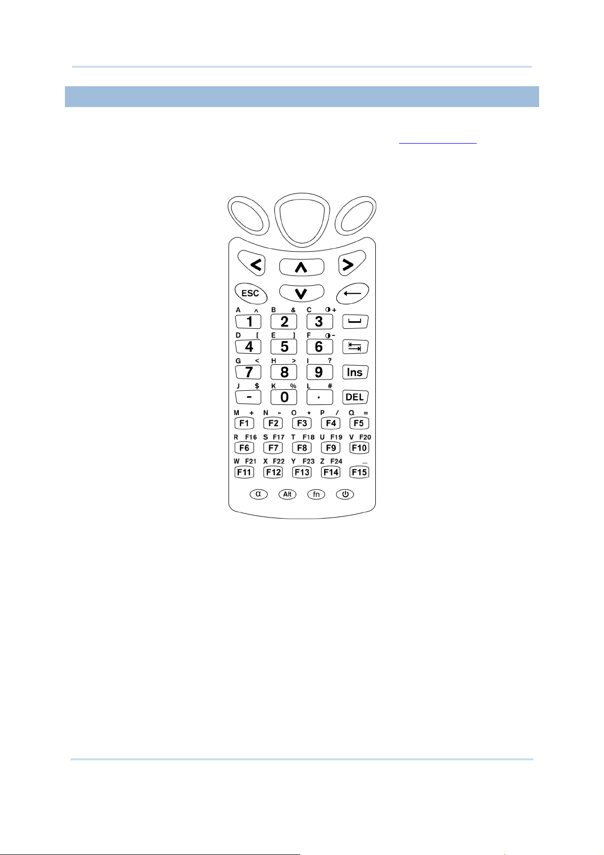
1.3.1 24-KEY LAYOUT
The l ayout of t he 2 4-key ke ypad i s si milar to a tel ephone keypad. It wedges
alphanumeric, navigation, function keys, and a few symbol keys. Refer to Appendix III —
Key Reference Tables
for all the characters it enters.
Figure 4: 24-key Layout
14
Page 25

Chapter 1 Using mobile computer
This 24-key alphanumeric keypad enters num bers by default. The ke ypad’s alphabet key
switches the keypad to al phabetic input. A few sy mbols are supp orted when the
keypad sits in alphabetic input, whether uppercase or lowercase.
Press the [α] key (repeatedly) until the mob ile computer shows a n “A”, whi ch we
might as well call “the alphabet icon”, at the lower-left of the screen. The keypad starts
to enter all caps and a few symbols without holding down the [α] key.
Press the [α] key
(repeatedly) until the mo bile computer shows a n “a”, whi ch we
might as well call “the alphabet icon”, at the lower-left of the screen. The keypad starts
to enter all lowercase letters and a few symbols without holding down the [α] key.
Note the letter case doesn’t impact the symbols.
An overview of the alphabet icons and the keypad’s input mode:
Alphabet Icons
None Numbers, hyphen minus “-”, and dot “.”
A All uppercase letters and symbols
a All lowercase letters and symbols
Keypad’s Input Mode
When inputting alphabetic characters, the l etters and the number printed on a k ey take
turn to show where the cursor is when you keep pressing that key; each press must not
exceed one second. Fo r example, when you keep press the num ber key [2], the letters
“A”, “B”, “C” and the number “2” take turn to show for uppercase while “a”, “b” , “c” and
“2” will take turn to show for lowercase.
When you first press the number key [2], the letter “A” or “a” is produced.
When yo u press the n umber key [2] t wice (t he ti me i nterval must not exceed one
second), the letter “B” or “b” is produced.
When yo u press the number key [2] three times (the ti me i nterval between each
press must not exceed one second), the letter “C” or “c” is produced.
When you press the number key [2] four times (the time interval between each press
must not exceed one second), the number “2” is produced.
In order to get the desired character, you ne ed to press the same key one to four times
(the time interval between each press must not exceed one seco nd). Only when the
pressing stops for longer than one second or another key is pressed will the system send
out the due key code or change over to send another key code to the active application
program.
The [f n] key
associated icon F
is pressed with a nu mber key . Upon you r pressing [f n] k ey, it s
displays at the bottom-left of the screen of the mobile computer. Press
the second key, sa y [ 5], to com plete the key combi nation and pr oduce [F5] fu nction.
Then the icon F
goes off automatically.
15
Page 26

8700 Series Mobile Computer Reference Manual
Functions of the common keys are briefly described as below:
SCAN
Triggers the scan engine so it reads a barcode when reader function is enabled.
ENTER
The two [Ent er] keys on both si des of the [S CAN] key are use r-friendly and
convenient for both right-handed and left-handed operators.
Both keys execute commands or confirm input.
Press the [fn] key the pre ss either of these [Enter] keys to turn on/off
backlight for the LCD and keypad.
Navigation Keys
These keys move the cursor left, up, down, or right.
Press the [fn] key then press either of up/down key to decrease/increase
LCD contrast.
Press th e [fn ] key then press either of l eft/right key to decrease/increase
the LCD backlight brightness.
the
ESC (Escape)
← (Backspace)
α (Alphabet Key)
Stops and quits the current operation.
Deletes the precedi ng character where the cursor is. If this key is pressed and
held, a clear code is sent.
This key is a modif ier k ey that requ ires a second key pressed to get th e
yellow-engraved letters (A~Z) and symbols.
Icon Description
A This icon appears at t he lo wer-left o f t he s creen to in dicate keypad
set to enters all uppercase letters and symbols.
a This icon appears a t t he lo wer-left o f t he s creen to in dicate the
keypad set to enters all lowercase letters and symbols.
16
Page 27

Chapter 1 Using mobile computer
fn (Function Key)
This key is a modif ier key that requir es a second key ([0] ~ [ 9]) pressed to
deliver the value of key combination.
Icon Description
F In default state, the functi on toggl e i s set to “Auto Resume” and
operates as described below:
This icon appears when you press the function key [fn], indicating
the keypad s et to the functi on key input. Press a second key to
get the desired function.
POWER Key
In order to prevent an ac cidental press of the PO WER key, you need to press
and hold this key for approxi mately 1.5 seconds to turn on/ off the mobil e
computer.
Note: (1) Fu nctionality of keys i s appli cation-dependent. The system will send the
associated key code to the application pr ogram, an d it is u p t o t he applicat ion
program to interpret the key code.
(2) As long as a status icon appears on the screen, it indicates a certain mode has
been activated and it isn’t necessary to hold the modifier key.
Once the second key is pressed, the icon goes off automatically.
17
Page 28
8700 Series Mobile Computer Reference Manual
1.3.2 44-KEY LAYOUT
The 44- key keypad wedges numeric, al phabetic, navi gation, f unction keys and the
modifier keys. Refer to Appendix III — K ey Reference Tables: 44-key Keypa d
characters it enters.
for all the
Figure 5: 44 key Layout
18
Page 29

Chapter 1 Using mobile computer
In default state, this 44-key alphanumeric keypad enters numbers and launches the
functions of F1 through F15.
THE [ALPHA] KEY
Press the blue modifier key [ α] to toggle the keypad among numeric, uppercase
alphabetic, and lowercase alphabetic modes.
Press the [ α] key
(repeatedly) until the mob ile computer shows an “ A”, whi ch we
might as well call the “alphabet icon”, at the lower-left of the screen. The keypad starts
to enter all uppercase letters without the need to hold down the [α] key.
Press the [ α] key
(repeatedly) until the mobile co mputer shows an “ a”, wh ich we
might as well call the “alphabet icon”, at the lower-left of the screen. The keypad starts
to enter all lowercase letters without the need to hold down the [α] key.
An overview of the alphabet icons and the keypad’s input modes:
Alphabet Icons
None Enters numbers, hyphen minus “-”, and dot “.”
Keypad’s Input Mode
Launches F1 through F15.
A All uppercase letters
a All lowercase letters
THE [FN] KEY
The orange [fn] key makes the ke ypad enter the orange-engraved characters. After the
[fn] key is pressed, it requires you to press a second key to complete the action.
Here are the basi cs how this [fn] key works: You first press the orange [fn] key
see an ico n F
sh ows at th e low er-left of th e screen. T hen you press another ke y
engraved with an orange-colored character/graphic to produce the following:
and
1) Entering that orange-colored character (mostly symbols).
2) Launching the functions of F16 through F24.
3) Increasing/decreasing backlight brightness for the screen and the keypad.
The [fn] ke y is set to “Auto Resu me” by default, which mean s the [ fn] k ey is en abled
once pressed, and becomes disabled once the second key is pressed.
Here’s an example how you produce the function of [F16]:
1) Press the orange [fn] key
The mobile computer’s screen shows an F
.
at the lower-left of the screen.
2) Press the key [F6], which is engraved with the orange-colored “F16”.
The system produces the function of [F16].
The icon F
goes off.
19
Page 30

8700 Series Mobile Computer Reference Manual
Functions of the common keys are briefly described as below.
SCAN
Triggers the scan engi ne so i t reads a barcod e when the re ader functi on i s
enabled.
ENTER
The two [Ent er] keys on both si des of the [S CAN] key are use r-friendly and
convenient for both right-handed and left-handed operators.
Both of them execute commands or confirm input.
Press the [fn] key then press either of these [Enter] keys to turn on/off
backlight of LCD and keypad.
Navigation Keys
These keys move the cursor left, up, down, or right.
Press the [fn] key then press either of up/down key to decrease/increase
LCD contrast.
Press th e [fn ] key then press either of l eft/right key to decrease/increase
the LCD backlight brightness.
the
ESC (Escape)
← (Backspace)
9
(Space)
) (Tab)
Ins (Insert)
DEL (Delete)
Stops and quits the current operation.
Deletes the p receding character where the cursor i s. If thi s key is pressed and
held, a clear code is sent.
Inserts a blank space at the position where the cursor is.
Moves the cursor to the next tab stop.
Switches the keypad between the overtype mode and insert mode. This key
helpful when the mobile computer is working on terminal emulation.
In overtype mode, when you are typi ng, the curs or overwri tes any character
that is right after its current position. In insert mode, when you are typing, the
cursor inserts a character at its current position.
Deletes the character at the back of the cursor.
is
20
Page 31

Chapter 1 Using mobile computer
α (Alphabet Key)
Alt Key
This key is a modif ier key that requ ires a second key presse d to produce
blue-engraved letters (A~Z).
Icon Description
A This icon appears at the lo wer-left o f t he s creen t o in dicate ke ypad
set to enter all uppercase letters.
a This icon appears at the lo wer-left o f t he s creen t o in dicate ke ypad
This key is a modif ier key that alters the next key pressed. The functiona lity
depends on the application that is active at the moment.
set to enter all lowercase letters.
Icon Description
A This icon a ppears wh en yo u press [Alt] to enter the special function
mode.
the
fn (Function Key)
This key is a modif ier k ey that requ ires a second key pressed to enter the
orange-engraved characters (mostly symbols) and produce the function of F16
through F24.
Icon Description
F The function toggle is set to “Auto Resume” by default which operates
as described below:
This i con ap pears when you press th e orange mo difier key [fn],
indicating the keypad set to function key input. Then you press a
second key to enter the desi red symbol s or produce the desired
function.
Once the second key is presse d, the icon F goes
Power Key
In order to p revent an ac cidental press of the PO WER key, you need to pr ess
and hold down this key for approximately 1.5 seconds to turn on/off the mobile
computer.
Note: (1) Functionality of key s is applicat ion-dependent. T he sy stem will sen d th e
associated key code to the a pplication pr ogram, an d it is u p t o the applicat ion
program to interpret the key code.
(2) Wh en a st atus icon appears on th e low er-left of the screen, it in dicates a
certain mode is activated and it is not necessary to hold down the modifier key.
automatically.
off
21
Page 32

8700 Series Mobile Computer Reference Manual
1.4 LCD
The mobile computer ships with a 3” FSTN graphic LCD, 160 by 16 0 pixels res olutions,
which can be programmed to display text or graphics such as specific font and company
logo to meet various applications.
Options
English font Font size 6×8 (pixels)
Chinese font Font size 12×12 (pixels)
Other language fonts, company logo… Programmable
Font Size (pixels) Characters by lines
26 characters by 19 lines
Font size 8×16 (pixels)
Font size 16×16 (pixels)
20 characters by 9 lines
13 characters by 12 lines
10 characters by 9 lines
Note: The bot tom lin e ( ICON_ZONE) is reserved t o display st atus icon s, su ch as th e
battery icon.
1.4.1 ADJUSTING THE BACKLIGHT
The backl ight of s creen and keypad makes i t easier to operate the mobile computer in
dim envi ronments. By pressi ng t he fol lowing key com binations, L CD ba cklight ca n be
turned o n/off a nd t he brightness can be adj usted. Kee p pressing the key co mbination
until the br ightness or contras t d ecreases or increases to a desired level. Alt ernatively
the brightness and contrast are controllable through programming or via System Menu.
Refer to
3.2.2 Backlight
Note: Using back light on batt ery pow er w ill su bstantially redu ce bat tery pow er. We
suggest th at y ou dim the back light while work ing in a w ell-lit area or set it to
automatic power off when the computer isn’t actively used.
and 3.2.13 Contrast.
Use the following key combinations to adjust the backlight for the mobile computer’s LCD
and keypad, and also the contrast for the LC D. Combine the keys by pressing the [fn]
key first and then pressing the second key.
Key Combination
24-key 44 key
+ [Enter]
+ [Up]
+ [Down]
+ [Right]
+ [Left]
+ [3] Same as + [Up]
+ [Enter] Toggles on/off the backlight
+ [Up] Increases the contrast of LCD
+ [Down] Decreases the contrast of LCD
+ [Right] Turns on the backl ight a nd i ncreases the bri ghtness of
+ [Left] Turns on the backl ight and decr ease the bri ghtness of
Action
LCD/keypad backlight.
LCD/keypad backlight.
22
Page 33

Chapter 1 Using mobile computer
+ [6] Same as + [Down]
1.4.2 CALIBRATING THE SCREEN
This LC D i s a touc h s creen that supports to uch control by a stylus. It also f eatures
signature c apture so signatures can be saved to serve as receipt confirmation whe n
goods are delivered to door.
Refer to
3.2.8 Screen Calibration
for screen calibration.
Warning: DO NOT contact the screen surface with any pointed or sharp object.
23
Page 34

8700 Series Mobile Computer Reference Manual
1.5 NOTIFICATIONS
1.5.1 STATUS LED
A LED indic ator is recessed above the [SCAN ] button. It presents d ual modes and each
mode presents dual colors. This LED indicator can be programmed to provide information
that helps di agnosing the stat us of the mobile computer. For exampl e, if you are usi ng
AG Ru ntime, y ou w ill b e in formed of t he scann ing resu lt immediately. LE D1 is u sed f or
"Good Read" and will become solid green upon reading a barcode successfully.
LED1 provides the information on the charging status and barcode reading.
LED2 provides the information on wireless communications.
LED1: Red/Green
User Power ON User definable User definable
Red Green
Solid green for Good Re ad by
default
Power Off, B attery
Charging
Charging Error System default
System default
Flashing red: Charging
System default
Flashing green: Charging done
Flashing red and green: Charging error occurs
LED2: Blue/Green Blue Green
Bluetooth System default
---
Flashing b lue, q uickly: W aiting fo r
connection or connecting
Flashing blue, slowly: Connected
Wi-Fi --- System default
Flashing g reen, quickly: W aiting
for connection or connecting
Flashing green, sl owly:
Connected
1.5.2 AUDIO
The mobile computer has a low power transd ucer type buzzer that is programmable for
status feed back. I n pa rticular, its freque ncy and duration can be programmed for the
alert of Good Read in the provided terminal emulation programs.
1.5.3 VIBRATOR
The mobile compu ter is integrated with a vibrator t hat is programmable f or status
feedback. It mak es t he mobi le co mputer applicable t o w ork in noisy environments. In
particular, the vibrator can be programmed fo r the alert of Good Read in the provided
terminal emulation programs.
24
Page 35

Chapter 1 Using mobile computer
1.6 DATA CAPTURE
Options of different reader combination are supported including 1D+RFID and 2D+RFID.
For each combination, both readers can be initialized and ready for scanning at the same
time (dual mode operation). For example, if you press the [SCAN] trigger while running
the preloaded AG runtime on the mobile computer, it will read a barcode in position or an
RFID tag in proximity depending on which one comes first.
Note: You can not have 1D +2D scan e ngines i nstalled on the mobile computer because
they are both barcode readers.
Varying by the reader type installed, the supported sym bologies or tag types a re listed
below:
1D CCD scan engine
1D Laser scan engine
1D Long Range Laser scan engine (LR)
2D scan engine
RFID reader
1.6.1 SYMBOLOGIES SUPPORTED
A w ide v ariety of scan en gines is av ailable f or deliv ering f lexibility t o meet dif ferent
requirements. Depending on the scan engine integrated, the mobile computer is capable
of scanning barcodes of a number of symbol ogies that are enabled by defa ult while
running the preloaded AG runtime. Refer to
If you need to scan barcodes that are encoded in a symbology that is disabled by default
in AG run time, FORGE Application Generator ( ForgeAG.exe) ca n help you configure
symbology settings and reader settings. First, enable the desired symbolog ies in FORGE
Application Generator, and then do wnload the appl ication setti ngs to the mobi le
computer.
Note: In AG or C ipherNet run time, n ot all of the symbologies are enabled by defa ult.
Instead of r unning any of them, you can develop your own applications to control
the scan engine for data collection. For d etails on c onfiguring reader and
symbology settings, please refer to the documentation of the software you use.
Symbologies Supported (Default Setting: Enable/Disable) CCD/Laser LR 2D
Codabar Enabled Enabled Enabled
Code 11 Disab led Disabled
3.3.1 Reader
for functional test.
Code 93 Enabled Enabled Enabled
Composite
Code
25
CC-A/B Disabled
CC-C Disabled
TCIF Linked Code 39 Enabled
Page 36

8700 Series Mobile Computer Reference Manual
MSI Disab led Disabled Disabled
Plessey Disabled
Postal Codes Enabled
Telepen Disabled
Code 128
Code 2 of 5
Code 3 of 9
EAN/UPC
Code 128 Enabled Enabled Enabled
GS1-128 (EAN-128) Enabled Enabled Enabled
ISBT 128 Enabled Enabled Enabled
Industrial 25 (Discrete 25) Enabled Enabled Enabled
Interleaved 25 Enabled Enabled Enabled
Matrix 25 Disabled Disabled
Chinese 25 Disabled
Coop 25 Disabled
Code 39 Enabled Enabled Enabled
Trioptic Code 39 Disabled Disabled
Italian Pharmacode (Code 32) Disabled Disabled Disabled
French Pharmacode Disabled
EAN-8 Enabled Enabled Enabled
EAN-8 Addon 2 Disabled Disabled Disabled
EAN-8 Addon 5 Disabled Disabled Disabled
EAN-13 Enabled Enabled Enabled
EAN-13 & UPC-A Addon 2 Disabled Disabled Disabled
GS1 DataBar
(RSS)
EAN-13 & UPC-A Addon 5 Disabled Disabled Disabled
Bookland EAN (ISBN) Disabled Disabled Disabled
UPC-E0 Enabled Enabled Enabled
UPC-E1 Disab led Disabled Disabled
UPC-E Addon 2 Disabled Disabled Disabled
UPC-E Addon 5 Disabled Disabled Disabled
UPC-A Enabled Enabled Enabled
GS1 Dat aBar Om nidirectional
(RSS-14)
GS1 DataBar Truncated Disabled Enabled Enabled
GS1 DataBar Stacked Disabled Enabled Enabled
GS1 DataBar Stacked Omnidirectional Disabled Enabled Enabled
GS1 DataBar Limited (RSS Limited) Disabled Enabled Enabled
GS1 D ataBar Expanded (RS S
Expanded)
GS1 DataBar Expanded Stacked Disabled Enabled Enabled
Disabled Enabled Enabled
Disabled Enabled Enabled
26
Page 37

Chapter 1 Using mobile computer
2D
Symbologies
PDF417 Enabled
MicroPDF417 Enabled
Data Matrix Enabled
Maxicode Enabled
QR Code Enabled
27
Page 38

8700 Series Mobile Computer Reference Manual
1.6.2 RFID TAGS SUPPORTED
The RFID reader supports read/write operat ions depend ing on the tags. The s upported
labels include ISO 15 693, Icode ®, IS O 14 443A, a nd ISO 1444 3B. Currently, the
performance of some tags has been confirmed, and the results are listed below for yo ur
reference. Refer to
3.3.9 RFID
Note: You should study the specifications of RFID tags before use.
HF Tag Protocol UID Read/Write
ISO 14443A
ISO 14443B
ISO 15693
Mifare Standard 1K (Mifare S50)
Mifare Standard 4K (Mifare S70)
Jcop41 (Mifare 1K & 4K compatible)
Mifare Ultralight
Mifare Ultralight C
Mifare ProX
Mifare DESFire
Mifare Plus
Mifare Mini (Mifare S20)
SLE66CLX320P
SLE55R04 / 08
Smart MX
Jewel
Topaz
SLE6666CL160S
SR176
SRIX4K
SLIX4K
ISO 14443A Compliant
ISO 14443B Compliant
EM4135
ICODE SLI
LRI12
LRI64
LRI128
LRI2K
SRF55V**P
SRF55V**S
for functional test.
9 9
9 9
9 9
9 9
9 9
9 9
9 9
9 9
9 9
9
9
9
9 9
9 9
9
9 9
9 9
9 9
9
9
9 9
9 9
9 9
9 9
9 9
9 9
9 9
9 9
--
--
--
--
-- Dual
--
28
Page 39

Chapter 1 Using mobile computer
Tag-it HF-I Std
TempSense
ICODE1 with EAS&AFI
ICODE
9 9
9
--
9 9
9 9
29
Page 40

8700 Series Mobile Computer Reference Manual
1.7 CHARGING & COMMUNICATIONS
Normally the mobile computer ships with a USB cable for charging and communi cations.
A variety of cradles are also developed and made available to you to meet your needs.
USB Interface Cable
Task USB Cable
Charging USB direct charging
500 mA: USB icon
0 mA: Disable charging for 8700
5 V charging from the adapter (Plug icon)
Communications USB Virtual COM — If you have FORG E Application Generator instal led on
your PC, you may use a download ut ility to receive data from your PC; or
you can run HyperTerminal.exe to receive data directly.
USB HID — Run a text editor on your PC to receive data directly.
USB Virtual COM_CDC —If you have FORGE Application Generator installed
on your PC, you may use a download utility to receive data fro m your PC;
or you can run HyperTerminal.exe to receive data directly.
Note: (1) If you are u sing USB Virt ual COM for the first time, you must install its driver
from t he CD -ROM. Driver v ersion 5. 3 or lat er is requ ired. P lease remov e old er
versions! The virtual COM port will not be assigned until the USB port is in use.
(2) If y ou are u sing USB Virt ual C OM_CDC for t he first t ime, y ou mu st in stall it s
driver from the CD-ROM. USB CDC driver installer can be f ound in the “Windows”
folder. It will proceed to install the driver to your PC.
(3) A standard USB cabl e releases a COM por t in the fol lowing conditions: (i) the
cable is det ached from t he mobil e compu ter direct ly, (ii) t he cable is det ached
from t he cradle direct ly, (iii) t he cable is at tached t o t he cradle, bu t the mobi le
computer is removed from the cradle, (iv) the mobile computer is powered off, (v)
no application that requires a virtual COM port is running on the mobile computer.
(4) For an application program that requir es a COM port to be oc cupied all t he
time, it is suggested that you use a 308 USB Virtual COM Interface cable instead.
30
Page 41

Chapter 1 Using mobile computer
RS-232 Interface Cable
Task RS-232 Cable + 5V Power Adapter
Charging 5 V charging from the adapter (Plug icon)
Communications If you have FORGE Appl ication Generator i nstalled on your PC, you may
use a down load utili ty t o recei ve da ta from your PC; or you can run
Cradle
Task Cradle Interface + 5V Power Adapter
Charging 5 V charging from the adapter (Plug icon)
HyperTerminal.exe to receive data directly.
Communications Depends on the cradle type and its associated settings —
USB
RS-232
Note: Battery ch arging stops wh en the temperature drops below 0°C or e xceeds 40°C .
It is recommended that the battery be charged at roo m temperature (18 °C to
25°C) for optimal performance.
31
Page 42

8700 Series Mobile Computer Reference Manual
1.7.1 INTERFACE CABLE OPTIONS
When charging by the USB cable, the standard charging current is 500 mA. However, it is
recommended that yo u charge the mobile computer b y the exte rnal power source
through the power adapter to speed up charging the battery.
If you want to disable char ging for 8700, change the cha rging current to 0 mA after
connecting the USB cable. Refer to 3.2.10 USB Charge Current
.
Push & release
Universal Power Adapter
Figure 6: Using USB/RS-232 cable
Warning: It is not allow ed f or the mobile compu ter to run solely by USB power
without a battery l oaded. It will di splay a war ning message “ Battery
Missing” along with an audible a lert. In th is case, y ou should in stall t he
battery before restarting.
1.7.2 CHARGING & COMMUNICATION CRADLE
The cradle supports charging and data connection at the same time.
1) Seat the mobile computer in the cradle.
2) Connect the power supply cord to the power receptacle on the cradle.
3) Connect the adapter’s wall-wart plug to a power outlet.
32
Page 43

Chapter 1 Using mobile computer
4) Connect the charging & communication cable if data connection is required.
Note: (1) Tighten the two screw-in connectors to secure the cable.
(2) As the mobile computer will be charged via cradle, the power receptacle on the
charging & communication cable is inefficacious.
Figure 7: Setting up cradle
33
Page 44

8700 Series Mobile Computer Reference Manual
Charging & Communication Cradle
No. Description No. Description
1 LED Indicators (from left to right):
2 Charging Slot for the mobile computer
Charge
USB
TX/RX
Power
Refer to 1.7.3 Understandi ng the LED
Indicators
3 Charging Slot for Spare Battery 4 Cable Connector (USB or RS-232)
5 Power Jack
.
34
Page 45

Chapter 1 Using mobile computer
1.7.3 UNDERSTANDING THE LED INDICATORS
The LED indicators on the cradle deliver the cradle’s status. For the charging status of the
mobile computer’s main battery pack, check out the device’ screen.
Figure 8: Cradle LEDs
Indicator
Charge
Status Description
Off Charging failed
Red, solid Charging spare battery
Green, solid Charging done
Off No USB connection USB
Green, solid USB plug-in
Off No activity TX/RX
Green, flashing Transmitting data via RS-232
Off No power POWER
Red, solid Power ON
Warning: Charging e rror may occur due to a power failure or defected battery
contacts.
35
Page 46

8700 Series Mobile Computer Reference Manual
1.8 SD CARD
A SD card i nserted in the mobil e c omputer is direct ly acc essible for user’s applications.
Yet when the mobile c omputer connects to the host computer via a USB cable, the SD
card can work as a removable disk (USB mass storage device) as long as it is conf igured
properly through programming or via System Menu | 8. Next Page | 1. SD Card
Menu | 1. Run As USB Disk. Refer to
Note: While running BASIC application, the size of DAT files on SD card can be calibrated.
Go to System Menu | 8. Next Page | 1. SD Card Menu | 2. Access SD Card | 4.
Check File Size to refresh the size of “A:\BASICRUN\TXACTn.DAT” (n=1~6).
3.8 SD Card Menu
.
1.8.1 FILE SYSTEM
For 8700 Series, SD cards of FAT12/FAT16/FAT32 file systems are sup ported and card
formatting through C programming or via System Menu | 8. Next Page | 1. SD Card
Menu | 2. Access SD Card is supported. Based on the capacity of the car d, it will
automatically decide the FAT format:
Card Capacity
> 8 GB
≦ 32 MB
≦ 1 GB
≦ 2 GB
≦ 8 GB
FAT Format Sectors per Cluster
FAT32 16
FAT12 32
FAT16 32
FAT16 64
FAT32 8
1.8.2 DIRECTORY
Unlike the file system on SRAM , the file system on SD ca rd suppor ts hierarchical tree
directory structure and allows creating sub-d irectories. Seve ral directories are reserved
for particular use.
Reserved Directory
\Program
Related Application or Function Remark
System Menu | Load Program
Program Manager | Download
Program Manager | Activate
Kernel Menu | Kernel Update
This di rectory stores the programs t hat are
downloadable to the mobile computer:
C program — *.SHX
BASIC program — *.INI and *.SYN
UPDATE_BASIC()
\BasicRun BASIC Runtime This directory stores the DAT and DBF fil es
that are cr eated an d accessed i n BASIC
runtime.
They are assi gned the permanent filenames
as follows:
36
Page 47

Chapter 1 Using mobile computer
DAT Filename
DAT file #1 TXACT1.DAT
DAT file #2 TXACT2.DAT
DAT file #3 TXACT3.DAT
DAT file #4 TXACT4.DAT
DAT file #5 TXACT5.DAT
DAT file #6 TXACT6.DAT
DBF Filename
DBF file #1
DBF file #2
Record file F1.DB0
System De fault
Index
Index file #1 F1.DB2
Index file #2 F1.DB3
Index file #3 F1.DB4
Record file F2.DB0
System De fault
Index
Index file #1 F2.DB2
F1.DB1
F2.DB1
DBF file #3
DBF file #4
DBF file #5
Index file #2 F2.DB3
Index file #3 F2.DB4
Record file F3.DB0
System De fault
Index
Index file #1 F3.DB2
Index file #2 F3.DB3
Index file #3 F3.DB4
Record file F4.DB0
System De fault
Index
Index file #1 F4.DB2
Index file #2 F4.DB3
Index file #3 F4.DB4
Record file F5.DB0
System De fault
Index
Index file #1 F5.DB2
F3.DB1
F4.DB1
F5.DB1
Index file #2 F5.DB3
Index file #3 F5.DB4
37
Page 48

8700 Series Mobile Computer Reference Manual
\AG\DBF
\AG\DAT
\AG\EXPORT
\AG\IMPORT
Application Generator (a.k.a. AG) This di rectory stores the DAT, DBF, and
Lookup fil es that are created and/or
accessed in Application Generator.
1.8.3 FILE NAME
A f ile n ame mu st follow 8. 3 f ormat ( = sh ort filenames) — at most 8 c haracters for
filename, and at most three characters for filename ex tension. T he following characters
are unacceptable: “ * + , : ; < = > ? | [ ]
On 8700 Se ries, it can only display a filename of 1 ~ 8 characters (the null character
not in cluded), and f ilename ex tension w ill b e display ed if prov ided. If a f ile n ame
specified is longer than eight characters, it will be truncated to eight characters.
Long filenames, at most 255 characters, are allowed when using the mobile computer
equipped with SD card as a mass storag e devi ce. For exampl e, you may ha ve a
filename “123456789.txt” created from yo ur PC. However, whe n the same file is
directly ac cessed on the mobile computer, the filename wi ll be tru ncated to
“123456~1.txt”.
If a file name is not specified in ASCII characters, in order for the mobile computer to
display it c orrectly, y ou may n eed t o dow nload a mat ching f ont f ile t o t he mobile
computer first.
The file name is not case-sensitive.
38
Page 49

Chapter 2
LEARNING SOFTWARE ARCHITECTURE
This chap ter describes the softwar e preinsta lled on the mobile computer — the Kernel,
System, and Application, and each has its own function menu.
When a menu displays, select an item by either of the following ways:
Press t he navigation k eys [Up ] a nd [Down] to move be tween the menu items and
press [Enter] to select one.
Press the number key that corresponds to the menu item to select it.
Use a stylus to tap an item from the menu to select it.
Follow the on-screen instructions to change a setti ng, or press [ ESC] to return to a
previous page or menu.
39
Page 50

8700 Series Mobile Computer Reference Manual
On each screen, the bottom line displays status icons, such as:
The 4-bar battery icon indicates the current power status.
The status icon of input mode is controlled by the modifier key: or
The status icon of function mode is controlled by the modifier key: or
The turn-page icon ( ) indicates there is a previous page or menu.
To return to a previous page or menu, yo u may press [ESC], touch the menu title, or
follow the on-screen instructions.
Figure 9: Software Architecture
IN THIS CHAPTER
2.1 Application Module..................................................... 41
2.2 System Configuratio
n & Core....................................... 43
40
Page 51

Chapter 2 Learning Software Architecture
2.1 APPLICATION MODULE
The mobile computer ships with the software package on the CD-ROM. It includes
FORGE Application Generator (batch- an d WLAN- versions), MIRROR Emulator (V T
and 5250 versions), download utilities, etc.
2.1.1 FORGE APPLICATION GENERATOR (AG)
For t he easy dev elopment of applicat ions, the mobile computer is preloaded with AG
runtime. Wh en y ou turn on the mobile com puter, it di splays u ser application’s main
menu as below.
Batch AG
WLAN AG
Note: Batch AG s upports a utomatically uploading data to a h ost comput er when t he
upload interface is properly configured. Once the mobile computer co nnects to the
host via a RS-232 or USB Virtual COM cable, a moving hourglass icon displays on
the upper-r ight corner of the scr een to i ndicate the mobile computer ready for
auto upload.
Before you proceed to collect data with the mobile computer, conf igure the applicat ion
with t he co mpanion to ol on your PC. T his time-saving development tool hel ps create
mobile computer’s application templates on your PC.
For details on the AG application, refer to related user manual.
Application Generator
Batch AG U8700.SHX ForgeA G.exe
WLAN AG WU8700.SHX A G8700WLAN.exe
AG Runtime on mobile computer Companion Tool on PC
Note: FORGE Application Generator (AG) software package includes
(1) a companion tool for quickly developing your application — Batch or WLAN AG;
(2) several download utilities to make it versatile in use.
41
Page 52

8700 Series Mobile Computer Reference Manual
2.1.2 MIRROR EMULATOR (CIPHERNET)
The mobile computer supports VT100/220 and IBM 5250 ter minal emulation for
accessing a backe nd d atabase. I nstead of using FORGE Application Generator, y ou
may downl oad the ter minal emu lation program, i.e. C ipherNet Runtime, to the mobile
computer. Refer to
3.6 Load Program
. T hen ru n i ndividual compani on tool on yo ur
computer.
For details on the MIRROR Emulator application, refer to associated user manuals.
Terminal Emulation CipherNet Runtime on mobile computer Companion Tool on PC
VT100/220 87xx-VT.SHX CipherNet-VT.exe
IBM 5250 87xx-5250.SHX Ci pherNet-5250.exe
2.1.3 USER PROGRAM
You may need to d evelop your own app lication program. For devel oping cus tom
applications, C ipherLab prov ides BASIC and C compilers through licen sing. For detailed
information, contact your sales representative.
42
Page 53

Chapter 2 Learning Software Architecture
2.2 SYSTEM CONFIGURATION & CORE
For managi ng s ystem confi gurations an d m ultiple programs, each mobi le computer
comes with System Menu, Program Manager, an d Kernel Menu. Th e following
chapters gu ide you to how the mobile computer is configured for system operation and
program download.
2.2.1 SYSTEM MENU
System Menu is bundled with BASIC Runtime or user programs that are written in “C”. It
is prov ided f or sy stem con figuration, fu nctionality t esting, dow nloading f ont f ile an d
program.
2.2.2 KERNEL
Kernel is the innermost core of the OS. It pro vides services f or u pdating the kernel and
bootloader, and repairing the system.
2.2.3 PROGRAM MANAGER
Program Manager is part of the kernel. You may download as many as seven applicat ion
programs.
43
Page 54

8700 Series Mobile Computer Reference Manual
44
Page 55

Chapter 3
SYSTEM MENU
System Menu is a powerful utility that offers an interface for engineers (programmers or
system integrators) to view sys tem inform ation, cha nge t he co nfiguration par ameters,
download programs and run diagnostics.
As System Menu is intended for engineers’ te sts and maintenance ONLY, pa ssword
protection is provided to pr event unauthorized users from accidentally changing system
settings.
Warning! System Menu is NO T for the use of any e nd users. The system password
helps ensure system safety and integrity.
How to access the System Menu?
1) Turn off the mobile computer.
2) Press [7] + [9] + [Power]
simultaneously.
45
Page 56

8700 Series Mobile Computer Reference Manual
IN THIS CHAPTER
3.1 Information............................................................... 46
3.2 Settings ................................................................... 48
3.3 Tests
3.4 Memory....................................................................
....................................................................... 52
55
3.5 Power ...................................................................... 56
3.6 Load Program
............................................................
3.7 Bluetooth Menu
......................................................... 60
57
3.8 SD Card Menu ........................................................... 67
Men
3.9 Serial PPP
u......................................................... 69
3.10 Wi-Fi Menu.............................................................. 71
3.11 DoFTP Menu ............................................................ 80
3.12 3.5G Menu .............................................................. 82
3.1 INFORMATION
Select this command to generate the critical system information that helps diagnose the
system.
System Menu | 1. Information
H/W Hardware version
S/N A serial number assigned to the mobile computer
M/D Manufacturing date
KNL Kernel version
LIB
BSC
USR Application program version
DEV 5-digit code for the recognition of the embedded hardware modules
C library version
BASIC R un-time ve rsion. This entry is only present when a BASIC a pplication h as
been downloaded
For example, 1410-1 indicates the 44-key mobile computer is equipped with the
CCD scan engine, RFID reader, Bluetooth module, and 802.11b/g connectivity.
rd
RFID This RFID m odule ve rsion is only p resent when t he 3
above appears 1.
di git of the D evice Code
46
Page 57

Chapter 3 System Menu
3.1.1 UNDERSTANDING DEVICE CODE
The device code covers a few pieces of information about the hardware housed inside the
mobile computer. The coding rule is tabulated as follows:
Device Code
1st digit Reader module 0= none
2nd digit Wireless module 4= Bluetooth + 802.11b/g
3rd digit RFID, GPS module 0= none
4th digit Reserved 0
5th digit Keypad layout 0= 24-key
Modular Component Coding
1= CCD scan engine
2= Laser scan engine
3= 2D scan engine
4= Long Range Laser scan engine
5= Bluetooth only
7= Bluetooth + 3.5G + 802.11b/g
1= RFID reader
2= GPS
1= 44-key
(8770)
(8700)
(8790)
47
Page 58

8700 Series Mobile Computer Reference Manual
3.2 SETTINGS
This subm enu access es the mobile compu ter’s syste m settings and c hanges their
defaults.
An overview of the defaults:
System Settings
Clock Current time
Backlight 20 seconds, Level 2
Auto Off 10 minutes
Power On Options Resume
Key Click Tone 2
System Password Open access
Font System font
Screen Calibration Select thi s command to align the co ordinates of the touch
USB VCOM No. Fixed
USB Charge Current 500 mA
Default Set (=Reset to Default) Restores your mobile computer to default state.
Reset Reader Restores the reader to default state.
Contrast Level 4
Default Values
screen wi th those of the di splay underneath i t, so as to make
the touch control precise.
3.2.1 CLOCK
Sets the clock / calendar time for the mobile computer. Enter two digits for the year, e.g.
04 for 2004.
3.2.2 BACKLIGHT
Sets the backlight duration for the keypad and LCD.
Enter a value between 0 and 9999 (seconds).
Press the navigation keys [Up] and [Down] to adjust the backlight level (4 levels).
48
Page 59

Chapter 3 System Menu
3.2.3 AUTO OFF
Sets the m obile computer to automatically power off after idleness for a period of time.
Enter a value between 0 and 999 (minute).
Note: To disable this function, enter 0.
3.2.4 POWER ON (& WAKEUP EVENT) OPTIONS
This i s a su bmenu t hat confi gures how the mobile computer starts up a nd what event
wakes up the mobile computer:
Power On Options
Press the na vigation keys [Up] and [D own] to sel ect betwee n “Resume” and “Restart ”. Press
[Enter] to select it.
Resume: When the mobile computer is powered on, it resumes the last session of the program
that was run before it is turned off.
Restart: When the mobile computer is powered on, the system restarts over.
WakeUp Events
The events set can wake up the mobi le computer when i t takes place. Pres s the navi gation keys
[Up] and [Down] to move between the events, and press [Enter] to configure it to enforce the
wake-up of the mobile computer or not.
PwrKey: If set to yes, the mobile computer wakes up when the power key is pressed.
RS232: If se t to yes, the mobi le computer wakes up when connected to a RS-232 por t (by
RS232 cable).
USB: If set to yes, the mobi le computer wakes up when connected wi th to a USB port (by a
USB cable).
Charging: If set to yes, the mobile computer wakes up when getting charged via the cradle or
direct charging.
Charged: If set to yes, the mobile computer wakes up when charging completes.
Alarm: If set to yes, the mobi le computer wakes up when the alarm time is up. Alarm can be
set up through programming only.
3.2.5 KEY CLICK
Sets the audible signal the mobile computer produces when a key is pressed on the
keypad. Select a desired tone for the buzzer or mute it.
3.2.6 SYSTEM PASSWORD
Sets a password to control over user’s access to the System Menu, Program Manager
and Kernel Menu. The password allows up to eight alphanumeric characters.
49
Page 60

8700 Series Mobile Computer Reference Manual
Note: The password is case-sensitive. To disable a previous password, press both [Enter]
when you are asked to "Input new password" and "Verify password".
3.2.7 FONT
Shows the font information. It displays “System Font” if no custom font file is a ctive on
the mobile computer. If a multi-language font file is downloaded, you are able to select a
font from the list.
3.2.8 SCREEN CALIBRATION
When a to uch screen has served for a period of t ime, it n eeds calibrat ion t o w ork
accurately. C alibration improv es t he accu racy of t he touc h scr een by al igning the
coordinates of the touch panel and the LCD underneath it.
“Screen Cal ibration” i s a command that launches the mobile computer’s acti on directly.
Upon your selecting this command, the screen di splay four cross marks, one at a time at
the fo ur co rners of the screen. A ccurately and firmly tap on the centers of these cross
marks using the stylus to follow through the calibration.
Warning: DO NOT use any pointed or sharp object to tap on the screen.
3.2.9 USB VCOM NO.
USB VC OM N o. is set t o “ Fixed” by def ault. “Fixed” m eans the m obile computer will
always connect to a host computer (such a s your PC) by the same USB Vi rtual COM port
regardless of how many mobile computers are connected to it earlier or later.
When the USB VCOM No. is set to “Fixed”, yo u can only connect one mobile computer to
your P C at one time. Such setting i s hel pful to configure a great amou nt of mobil e
computers (for administrators’ or factory use).
While in oth er cases, y ou may n eed t o set USB VC OM No. to “Change with S/N”, which
means the number of th e virtual COM port in use will vary by the serial number of each
mobile computer connected to your PC.
Press the n avigation k eys [U p] and [Down] to select be tween “Fixe d” a nd “Change
with Serial Number”.
3.2.10 USB CHARGE CURRENT
By default, the USB charging curr ent is se t to 500 mA. For direct charging via the USB
cable without a power adapter, the standard charging current is 500 mA.
Press the navigation keys [Up] and [Down] to select between “500 mA” and “0 mA”.
To disable charging the mobile computer, select “0 mA”.
50
Page 61

Chapter 3 System Menu
Note: (1) USB direct charging, 500 mA: USB icon
(2) 5V charging from the adapter: Plug icon
3.2.11 DEFAULT SET
Restores the system settings to default factory state, except for the reader settings.
3.2.12 RESET READER
Restores the reader settings to factory default state.
3.2.13 CONTRAST
Sets the contrast level for the LCD.
Press the navigation keys [Up] and [Down] to adjust the contrast level (7 levels).
51
Page 62

8700 Series Mobile Computer Reference Manual
3.3 TESTS
Provides a variety of functional tests on the mobile computer’s key parts.
3.3.1 READER
Launches the test on the scanner’s reading performance. Symbologies supported depend
on the scan engine you use. Refer to 1.6 Data Capture
default. Symbologies disabled by default can only be enabled through programming.
for the symbologies enabled by
Press the [SCAN] key to start testing. To stop and quit the test, press any key.
3.3.2 BUZZER
Launches the buzzer test with different frequency/duration combinations.
To stop and quit the test, press any key.
3.3.3 LCD & LED
Launches the test on the LCD display and LED indicator.
To stop and quit the test, press any key.
3.3.4 KEYBOARD
Launches t he test o n the keyp ad’s rubberized keys. Press any key to see if the
corresponding character display on the screen.
To stop and quit the test, press [ESC].
3.3.5 MEMORY
Launches the test on the mobi le computer’s data me mory (SRA M). The re sults wi ll
display on the screen.
To stop and quit the test, press [ESC].
Warning! The contents of the data memory (SRAM) will be wiped out after test.
52
Page 63

Chapter 3 System Menu
3.3.6 TOUCH SCREEN
Launches the test on the mobile computer’s signature capture with the help of the stylus.
To stop and quit the test, press [ESC] or tap [OK] on the screen.
3.3.7 VIBRATOR
Launches the test on the mobile computer’s vibrator.
To stop and quit the test, press [ESC].
3.3.8 ECHO TEST
Launches t he test on the mobi le computer ’s data con nection est ablished th rough the
physical USB cable or a RS-232 cable. Run the test utility on your PC while launching this
test on the mobile computer. Select a desired baud rate if necessary.
To stop and quit the test, press [ESC].
Interface
RS-232 This echo te st i s to veri fy the connectivity via the RS -232
USB
Description Test Utility
EchoTest.exe
cable between the mobile computer and a host computer.
This echo test is to verify the connectivity via the USB cable
between the mobile computer and a host computer.
USB VCOM Echo —
generic USB device.
The mo bile c omputer wo rks a s a
USB HI D — T he mo bile c omputer wo rks a s a n in put
device; sel ect keyboard t ype and Ca ps Lock statu s for
running a test.
USB VCOM_CDC Echo —
a generic USB device.
The mobile computer works as
EchoTest.exe for
Virtual COM
Any text editor for
HID
EchoTest.exe for
Virtual COM
3.3.9 RFID
Launches the test o n the RFID re ader’s reading performance whe n a proximity card is
present. Refer to 1.6.2 RFID Tags Supported
for the supported RFID tags.
To stop and quit the test, press [ESC].
Note: This test is available only when the RFID module is present.
53
Page 64

8700 Series Mobile Computer Reference Manual
3.3.10 GPS
Launches t he test on the mobi le computer’s GPS receiver. It gives a general review of
the mobile computer’s real t ime s peed an d posit ion in formation, and also t he sat ellite
count and signal strength.
To stop and quit the test, press [ESC].
Note: This test is available only when the GPS module is present.
54
Page 65

Chapter 3 System Menu
3.4 MEMORY
Delivers t he in formation about th e mobile compu ter’s memory . It also in itializes the
memory.
3.4.1 SIZE INFORMATION
Delivers an overview of memory information:
RAM — onboard SRAM for data memory
Flash — program memory
3.4.2 INITIALIZE
Initializes the data memory.
Warning! The con tents of th e data memory (SRAM) w ill be w iped out after memory
initialization.
55
Page 66

8700 Series Mobile Computer Reference Manual
3.5 POWER
Delivers the mobile computer’s current voltage consumption.
Main (battery)
Shows the dynamic status of the battery pack, which is the main power source.
Backup (battery)
Shows the dynamic status of the button cell, which supplies power to retain data in SRAM.
Warning! Always ex amine t he b attery icon on the de vice screen so you wi ll be
alerted for a low battery condition.
56
Page 67

Chapter 3 System Menu
3.6 LOAD PROGRAM
Launches t he mobi le computer’s L oad Program serv ice provided by the kernel. After a
program is downloaded to the mobile comp uter, you won’t be abl e to return to System
Menu by pressing [ESC] as the kernel will take over the job. In this case, restart the
mobile computer to activate the new program. Refer to Appendix I
Note: When RS-232 is selected for the transmission interface, the mobile computer stays
in download mode for about 30 seconds only. The preparation (such as connecting
the RS-232 cable) and the kernel update s hould be done before the download
mode expires.
Download Utility.
The following files are downloadable by Load Program command:
.SHX Program
Program File
Font File Refer to the Font Files folder on CD-ROM.
Downloadable C program files and/or font file:
AG Runtime:
CipherNet Runtime:
BASIC Runtime
Note
:
User program
U8700.shx (Batch AG)
WU8700.shx (WLAN AG)
87xx-5250.shx (CipherNet-5250)
87xx-VT.shx (CipherNet-VT)
B8700.shx
If you have downloaded a BASIC Runtime program, you will be able to select whether to
download a C program (.SHX) or BASIC prog ram (.S YN) the next ti me you acc ess t he
Load Program command.
Note: (1) “Load Basic” menu is on ly av ailable af ter y ou h ave down loaded a BASIC
Runtime program.
(2) In add ition to the sys tem font, t here can be on ly on e more font f ile
downloaded to the mobile computer.
57
Page 68

8700 Series Mobile Computer Reference Manual
SETTINGS
Interface
Options Description
RS232 Loading programs from RS232-interfaced devices such as your PC. The
mobile computer nee ds t o connect to your PC with a RS 232 cable.
Baud rate setti ngs are necessary o n both your PC and the mobile
computer.
USB VCOM Loading programs from USB-i nterfaced devi ces such as Your P C. Th e
mobile computer needs to connect to your PC with a USB cable.
Bluetooth Loading programs from Bluetooth-enabled devices.
SD Card Loading p rograms d irectly fr om t he SD Ca rd in serted in t he mo bile
computer.
USB VCOM_CDC Loading prog rams from US B-interfaced devi ces such as Your P C. Th e
Baud Rate
Available baud rate options: 115200/57600/38400/19200/9600 bps
mobile computer needs to connect to your PC with a USB cable.
LOAD PROGRAM VIA BLUETOOTH
3) Go to System Menu | 7. Bluetooth Menu | 3. Security, a nd configure the
following Bluetooth settings first.
Authentication
PIN code
4) Go to System Menu | 6. Load Program and select Bluetooth.
5) Have y our PC in itiate t he pairin g w ith the mobile computer by clicking [Pair Device]
and/or [Connect Bluetooth Serial Port].
6) On y our PC, run the download utility ProgLoad.exe. In [C omm set ting] group box,
make the following settings:
- Select RS-232 for [Comm type], so as to access Bluetooth SPP.
- Configure [C OM port] properties according to the Bluetooth COM port generated
on your PC. Go to start | Control Panel | System | Hardware | COM & LPT to
check it up.
58
Page 69

Chapter 3 System Menu
LOAD PROGRAM VIA SD CARD
Press the navigation keys to move between
the files. Press [Enter] to select and view
the information of the selected program
file.
1) If you have copied the desired program file(s) to your SD card, go to System Menu |
6. Load Program and select SD Card. Yo u will s ee a list of all the files under the
directory “\Program”, as shown above.
2) Press the navigation keys [Up] and [Down] to move between the listed files.
3) Press [Enter] to view information of the program file.
4) Press [Enter] to confirm downloading the program file to the mobile computer.
Press [ESC] to abort the download task.
59
Page 70

8700 Series Mobile Computer Reference Manual
3.7 BLUETOOTH MENU
Sets the mobile computer to work with other Bluetooth devices. It takes correct settings
to enable the Bluetooth communication.
Bluetooth Settings
Connect Setting Items Need to Be Checked
Local Name
Remote Name
Broadcast Me
Power Saving
BT-GPRS AP Name
DHCP
Local IP Address
Security Items Need to Be Checked
Authentication
PIN Code
Default Value HID SPP DUN
Model no. + Serial no.
---
Enable
Enable
---
Enable
0.0.0.0
Disable
---
v
---
v
v
---
---
---
v
v
v
---
v
v
---
---
---
v
v
v
---
v
v
(v)
(v)
(v)
v
v
Note
Note
Note
Note: BT-GPRS AP Name, DHC P and local IP Address are required for DUN-GPRS m ode
only.
3.7.1 INFORMATION
Delivers the mobile computer’s Bluetooth network configuration.
Bluetooth Menu | 1. Information
LIB Kernel version
MAC MAC address of the Bluetooth module
IAM A name given to the mobile computer for identification
By defaul t, it i s comprised of the model number and the serial numb er.
(Identical to Bluetooth Menu | 2. Connect Set | 1. Local Name)
60
Page 71

Chapter 3 System Menu
CTY "Normal" means all 79 channels are available for frequency-hopping.
There are ba ndwidth limitations for 2.4 GHz IS M band i n some countri es. F or
example, only 23 RF channels are def ined in stead of 7 9 R F channels in J apan,
Spain and France.
DHCP DHCP server in use or not
It will automatically become enabled while connecting to a BT-GPRS AP.
IP IP address of the mobile computer
3.7.2 CONNECT SETTING
Sets the necessary parameters for mobile computer’s Bluetooth networking.
Local Name
Enter a name for identifying the mobile computer.
By default, it is comprised of the model number and the serial number.
Remote Name
Leave it empty unless you want to make a specific connection.
Broadcast Me
Options — Enable or Disable
For in itial connection, b roadcasting mu st be e nabled s o
the mobile computer.
other Bl uetooth devi ces can d iscover
For security concerns, you may disable it in future use to hide the mobile computer from other
Bluetooth devices.
Power Saving
Sets the mobile computer to the low power consumption mode.
Options — Enable or Disable (Only the Sniff mode is supported.)
BT-GPRS AP Name
For DUN-GPRS mode, enter the AP name for connecting to the content server.
DHCP
Options - Enable or Disable
Local IP Address
61
Page 72

8700 Series Mobile Computer Reference Manual
Enter a new address for the mobile computer, if necessary.
Note: BT-GPRS AP Name, DHCP and local IP Address are required for DUN-GPRS m ode
only.
3.7.3 SECURITY
Sets or modifies the security parameters for the mobile computer’s Bluetooth connection.
Authentication
Such “Authe ntication” concerns the pre-pairing vali dation between two Bl uetooth devi ces befor e
they can communicate with each other. Options available are Enable and Disable.
PIN Code
Enter a “Pin Code” to function fo r the encryption key value. P airing is only a chievable when two
Bluetooth devices present the same Pin Code.
Up to 16 characters, in ASCII format.
Note: When authentication i s enabled without providing a pr e-set PIN c ode, the mobile
computer supports dynamic input of PIN code during pairing.
3.7.4 ECHO TESTS
Launches the echo tests that verify the mobile computer’s Bluetooth connectivity to make
sure it sits within the wireless transmission range. Press [ESC] to stop and quit the test.
Some key terms addressed in the submenu are defined as follows:
SPP: Serial Port Profile
Bluetooth SPP i s for Bl uetooth-enabled devi ces suc h as the mobile
computer to wirelessly connect to an ad hoc network.
DUN: Di al-Up Networking Profile
Bluetooth DUN i s for Bl uetooth-enabled devi ces such as the mobile
computer to access the Internet and other dial-up services.
62
Page 73

Chapter 3 System Menu
- DUN Modem – Select this com mand to have the m obile computer
access a Bluetooth mo dem or mobile phone to use it as a wireless
modem.
- DUN GPRS – Select this command to have the mobile computer access
a GPRS-enabled mobile phone to connect to a GPRS AP.
HID: Human Interface Device Profile
Bluetooth HID enables the mobile computer to function as an input device
(such as a keyboard) f or anot her Bluetooth e nabled devi ce suc h as your
PC.
63
Page 74

8700 Series Mobile Computer Reference Manual
SPP Master
Sets the mobile computer as a master device.
1. Pairing with your PC (slave) must be completed first.
2. Run the utility “EchoTest.exe” on your PC. Associated settings include:
- Select “RS-232” for interface.
- Use the (incoming) Bluetooth COM port that has been paired.
- Set Action Mode to “Passive”.
3. Start the echo test on both sides. The mobile computer will try to connect to PC (slave).
SPP Slave
Sets the mobile computer as a slave device.
1. Enable Authentication and set PIN code on the mobile computer.
2. Run the utility “EchoTest.exe” on your PC. Associated settings include:
- Select “RS-232” for interface.
- Use the Bluetooth COM port that has been configured as “outgoing”.
- Set Action Mode to “Passive”.
3. Start the echo test on both sides.
4. The mobile computer will wait for PC (master) to start the connection.
5. Enter the preset PIN code for authentication on your PC.
DUN Modem
Sets the mobile computer to connect to a Bluetooth modem or mobile phone.
1. Pairing with that mobile phone must be completed first.
Select “DialUp Network” for Target Machine options.
2. Run the utility “EchoTest.exe” on your PC. Associated settings include:
- Select “Modem” for interface.
- Set Action Mode to “Passive”.
3. Start the echo test on both sides.
4. The mobile computer will connect to the mobile phone that dials up to your PC.
HID Test
Sets the mobile computer as an input device for another Bluetooth-enabled device.
1. Pair the mobile computer with another Bluetooth-enabled device (such as your PC) first
2. On the mobil e computer, sel ect HID Test. Configure keyboa rd type and upper/l ower case
mode when you are prompted to. Then the mobile computer enters HID test mode and tries to
make up B luetooth connection with your PC.
display a ready message on the screen. (It is suggested to that you disable the Authentication
on the mobile computer.)
3. On your PC, run a text editor.
4. You can proceed to input data via the mobile computer’s keypad.
As soon as the co nnection is reached, 8700 wil l
64
Page 75

Chapter 3 System Menu
DUN GPRS
Sets the mobile computer to connect to a mobile phone with 3.5G functionality.
1. Pairing with that mobile phone must be completed first.
On the mobile computer, under when you are prompted to select the type of the target device,
select “DialUp Network”.
2. Under the mobi le computer’s Echo Tests | 5. DUN GPRS command, enter the IP and port
number of the server.
3. Run the utility “EchoTest.exe” on your PC. Associated settings include:
- Select “TCP/IP – Server” for interface.
- Set Action Mode to “Passive”.
4. Start the echo test on both sides.
5. The mobi le computer wi ll connect to the mobile phone that di als up a GPRS AP, and fi nally
connect to your PC (server) through the GPRS AP.
3.7.5 PAIRING TEST
Launches the t est if pair ing is ach ieved bet ween tw o Blu etooth-enabled dev ices. P airing
deals with the procedure whereby two Bluetooth-enabled devices accept each other’s
connection request by creating an d exch anging a lin k k ey. Such lin k k ey remains
efficacious for authentication when the two Bluetooth-enabled device s are exchanging
information in the future
1) As soon as P airing Test is select ed, th e mobile compu ter starts to inquire the
discoverable Bluetooth device(s) nearby, and the system will generate a list of them.
2) Select a target device to test connection.
For th e device n ame, it can on ly display a max imum len gth of 11 ch aracters. When
the device name is too long, it will be truncated automatically.
3) Select a Bluetooth service from the “Target Machine” menu. To stop and quit the test,
press [ESC].
After pairing succeeds, the target device will be added to the Frequent Devices list for
quick connection in the future.
Note: For t he in itial u se of Blu etooth n etworking, the pairin g procedu re must be done
before the Echo tests.
65
Page 76

8700 Series Mobile Computer Reference Manual
3.7.6 FREQUENT DEVICES
Lists the devices the mobile computer has recently Bluetooth-connected to. Such list gets
updated ea ch time pairing is achieved for the mobile co mputer with another Bluetooth
device.
Listed are the connected devices with any of the following services:
Serial Port (SPP)
Dial-Up Networking (DUN)
Human Interface Device (HID)
For the device name, maximum 11 characters are displayed. When the device name is
longer, it is truncated automatically.
Note: To unpair any device, simply delete the device from this list.
66
Page 77

Chapter 3 System Menu
3.8 SD CARD MENU
Sets the mobile computer to a removabl e disk when equipped with a SD card. The files
on the SD card can be accessed directly.
Note: (1) As soon as a SD card is installed in the mobile computer, the card icon appears
at the bottom of the screen. When the SD card is accessed, such icon starts to
blink.
(2) As long as the mobile computer is pre installed w ith Batch AG ru ntime, it w ill
automatically create tw o working directories “\AG\IMPORT” and “\AG\EXPORT” as
soon as a SD card is inserted.
3.8.1 RUN AS USB DISK
When the mobile computer is eq uipped with a SD card and connected to your PC via a
USB cable, it runs as a removable disk (U SB mass storage device) as long as it is
configured properly through programming or via your selection of [Run as USB Disk].
Note: The SD card must be properly configured through programming or the menu here.
3.8.2 ACCESS SD CARD
Edits the files on the SD card or formats the SD card.
Edit Files
Views and edits the files on the SD card.
Format
Formats the SD card and recreates file system.
If the current file system on the SD card isn’t desired any more, you can format the SD card.
If the capacity is 32 MB or less, the file system recreated will be FAT12.
If the capacity is 32 MB~2 GB, the file system recreated will be FAT16.
If the capacity is more than 2 GB, the file system recreated will be FAT32.
Warning! The contents on the SD card will be wiped out after formatting.
67
Page 78

8700 Series Mobile Computer Reference Manual
Check Memory
Checks the memory size of the SD card inserted.
For an SD card that has never been used on the mobile computer, a message like “Found New
SD Card” will di splay a llowing users to scan the c ard for mem ory check. However you can
select cancellation and run the memory check later.
Check File Size
Calibrates the size of the DAT files on the SD card when running BASIC application. This command
also refreshes the size of “A:\BASICRUN\TXACTn.DAT” (n=1~6).
Note: “Check File Size” is on ly available after a BASIC Runtime program is downloaded
to the mobile computer.
68
Page 79

Chapter 3 System Menu
3.9 SERIAL PPP MENU
Enables the mobile computer to connect to a generic modem by serial PPP to access the
Internet. The parameters must be correctly set to establish the connection.
Point-to-Point Protocol (PPP) is a method of connecting the mobile computer to t he
Internet over seria l lin ks. It send s TCP/I P p ackets to a server tha t connects to the
Internet.
3.9.1 INFORMATION
Delivers the serial PPP library version.
Serial PPP Menu | 1. Information
LIB Kernel version
All user libraries reside in Kernel; no external libraries are required.
69
Page 80

8700 Series Mobile Computer Reference Manual
3.9.2 CONNECTION SET
Sets the mobile computer’s serial PPP connection to a generic modem.
DialUp Number
Enter the number provided by your ISP.
Login Name
Enter the login name provided by your ISP.
Login Password
Enter the login password provided by your ISP.
Baud Rate
Select a desired baud rate.
3.9.3 ECHO TEST
Launches t he echo t ests that verify the mobile computer’s connectivity through
Point-to-Point Protocol.
Connect the mobile computer to a generic modem and start the test.
Note: In Server I P field, en ter the IP a ddress of the server to be connected via PPP
protocol. The mobile computer will try to connect to the server. After t he PPP
connection is established, run the utility “EchoTest.exe” on your PC. In the control
panel of Ec hoTest.exe, set the co mmunication port to “TCP/IP–Server”. Start the
test on the mobile computer.
70
Page 81

Chapter 3 System Menu
3.10 WI-FI MENU
Sets the mobile computer’s 802.11b/g connection.
Note: This menu item is available only when the Wi-Fi module is present.
Wi-Fi Settings Default Value Ad-hoc Infrastructure
Network Setting Items Need to Be Checked
DHCP
SubNet Mask
Local IP Address
Default Gateway
DNS Server
Domain Name
WLAN Setting
Local Name
SS ID
System Scale
Power Saving
Preamble
Ad-Hoc
Fixed BSSID
Security
Authentication
WEP Menu
EAP Menu
WPA Menu
Enabled
255.255.128.0
0.0.0.0
0.0.0.0
0.0.0.0
---
Model no. + Serial no.
---
Medium
Enabled
Long
Disabled
000000000000
Open System
Disabled
Disabled
Disabled
---
v
v
---
---
---
v
---
---
---
---
v
---
---
---
---
---
v
v
v
v
v
v
v
v
v
v
v
--v
v
v
v
v
71
Page 82

8700 Series Mobile Computer Reference Manual
3.10.1 INFORMATION
Delivers the mobile computer’s Wi-Fi networking configuration.
Wi-Fi Menu | 1. Information
Lib Kernel version
All user libraries reside in Kernel; no external libraries are required.
Ver Firmware version of the Wi-Fi module
MAC MAC address of the Wi-Fi module
IAM A name given to the mobile computer for identification.
By default, it is comprised of model number and the serial number.
(Identical to 3. WLAN Setting | 1. Local Name)
DHCP DHCP server in use or not
IP IP address of the mobile computer
Mask Subnet Mask
Gate Default Gateway
72
Page 83

Chapter 3 System Menu
3.10.2 NETWORK SETTING
Sets the mobile computer’s Wi-Fi networking parameters.
DHCP
Options — Enable or Disable
Subnet Mask
Enter a new Mask IP, if necessary.
Local IP Address
Enter a new address for the mobile computer, if necessary.
Default Gateway
Enter a new address for the default Gateway, if necessary.
DNS Server
Enter a new address for the DNS server, if necessary.
Domain Name
When DHCP server is enabled, the domain name of the host displays in this field.
Note: Normally, DHCP is enabled by default, an d all re lated settings can be obt ained
from the DHCP server.
73
Page 84

8700 Series Mobile Computer Reference Manual
3.10.3 WLAN SETTING
Sets the m obile computer’s Wi-Fi connection that works in ei ther mode – (1) Ad-hoc
mode: peer-to-peer, or (2) Infrastructure mode: point to mu lti-point th rough access
points.
Set the following parameters:
Local Name
Enter a name for identifying the mobile computer.
By default, the name is comprised of the model number and the serial number.
SS ID
“SS ID ” means “Service Set Identifier”. It coul d be the na me of the A P for remote device
association.
As l ong as a n SS I D is set, the mobile computer can ONLY communicate with the devices of
the same SS ID.
System Scale
This refers to Access Point density.
Options — [1] Low [2] Medium [3] High [4] Customized
The setting must be consistent with that of the access point.
Set to “Low”, “Medi um”, or “High” to have the mobi le computer scan for other access points
when data transmission rate drops below “1”, “2” or “5” Mbps respectively.
Set to “Customized” to have the mobi le computer scan for other access points when the data
transmission rate drops below the following configurable values —
802.11b: 1, 2, 5.5, 11 Mbps
802.11g: 1, 2, 5.5, 11 Mbps & 6, 9, 12, 18, 24, 36, 48, 54 Mbps
Power Saving
This refers to the low power consumption mode.
Options — Enable or Disable
The setting must be consistent with that of the access point.
Preamble
Options — [1] Long [2] Short [3] Both
The setting must be consistent with that of the access point.
74
Page 85

Chapter 3 System Menu
Ad-Hoc
This refers to peer-to-peer mode, without going through access points.
Options — Enable or Disable
Fixed BSSID
This refers to the use of a specific AP’s MAC address as the fixed Basic Service Set Identifier.
When a Fixed BSSID is set, the mobile computer can ONLY communicate with the one and only
access point.
75
Page 86

8700 Series Mobile Computer Reference Manual
3.10.4 SECURITY
Sets or modifies the security parameters for the mobile computer’s Wi-Fi connections.
WEP: Wired Equivalent Privacy
EAP: Extensible Authentication Protocol
WPA: Wi-Fi Protected Access
Authentication
[1] Open System
[0] Share Key
“Open S ystem” is the defaul t. Where i t is set to “Open S ystem”,
there is no authentication.
If it is set to “Share Key”, a WEP key needs to be set up. See WEP
Menu in the following for details.
WEP Menu
WEP Setting
Enabled (It must be enabled i f you will opt or have opte d
“Share Key” for authentication.)
for a
Disabled (default)
WEP Key Length
64 bits
128 bits (default)
Default Key As the mobil e computer can store up to four WEP Keys, you can
configure one WEP key to take force here in this submenu. If you don’t
assign one, WEP KEY1 will be the default.
WEP Key This submenu enables the configuration of WEP Keys 1 to 4 in either
the following format:
ASCII (up to 13 characters)
Hexadecimal (up to 26 characters)
EAP Menu (for associating to Cisco access points)
EAP Setting
Enabled
Disabled (default)
EAP ID Enter a user name (up to 32 characters)
EAP Password Enter a password (up to 32 characters)
WPA Menu (WPA-PSK)
WPA Setting
Enabled
Disable (default)
of
76
Page 87

Chapter 3 System Menu
WPA2 Setting
Enable
Disable (default)
WPA Passphrase Enter a phrase as your password (8 ~ 63 characters)
3.10.5 ECHO TESTS
Launches the echo tes ts that verify if the mobile computer sits within the coverage of a
WLAN. It al so hel ps esti mate the number of APs a nd mobile computers nee ded, a nd
helps with the topology of APs deployment.
Client Mode
Select this item to set the mobi le computer as a cli ent. Ente r the IP address of the server to
connect to. The mobile computer will proceed to connect to an AP.
1. Enter the server IP and server port number on the mobile computer.
2. Run the utility “EchoTest.exe” on your PC. Associated settings include the following:
- Select “TCP/IP – Server” for interface.
- Set Action Mode to “Passive”.
3. Start the echo test on both sides.
Server Mode
Select this item to set th e mobi le computer as a server. The mobile computer wi ll proceed to
connect to an AP.
1. Run the utility “EchoTest.exe” on your PC. Associated settings include the following:
- Select “TCP/IP – Client” for interface.
- Set Action Mode to “Passive”.
2. Start the echo test on both sides.
While running echo tests, if WPA setting is enabled for security, the SSID and Passphrase
will be processed to generate a pre-share key.
Note: Once the SSID or Passphrase is changed, the pre-share key will be regenerated.
77
Page 88

8700 Series Mobile Computer Reference Manual
1) If the mobile computer is associating with an access point for the first time, there will
be an antenna icon developing on the screen to i ndicate that the m obile computer is
processing a pre-share key.
2) After a pre-share key is generated, the mobile computer proceed s to establish a
connection with the access point, and you will see the whole antenna flashing.
3) As soon as the connection is successfully made between the mobile computer and the
access poin t, y ou will see t he w hole an tenna w ith th e indication of w ireless si gnal
strength.
The changing icon (antenna icon)
indicates 8700 is processing
a pre-share key.
The antenna icon becomes ready and
flashes to indicate 8700 is connecting
to an access point under the same SSID.
Once connected, the antenna icon stops
flashing. Next to the icon, the more
bars show for stronger signals.
Note: If you are programming in C or BASIC, note the ant enna icon will appear on the
screen after NetInit() or START TCPIP() is called. (WPA must be enabled first!)
78
Page 89

Chapter 3 System Menu
When the echo test is ongoing, the details display as illustrated below.
SNR (dB)
(Signal to Noise ratio) (Transmit Speed) (Received Signal
0 ~ 10
10 ~ 20
20 ~ 30
30 ~ 40
over 40
Very Poor
Poor
Fair
Good
Very
Good
T RSS (-dBm) NF (-dBm)
Strength Level)
1
2
5.5
11
6
9
12
18
24
36
48
54
Mbps
Mbps
Mbps
Mbps
Mbps
Mbps
Mbps
Mbps
Mbps
Mbps
Mbps
Mbps
0 ~ 60
60 ~ 75
over 75
Strong
Moderate
Weak
(Noise Floor Level)
0 ~ 92
92 ~ 98
over 98
Strong
Moderate
Weak
79
Page 90

8700 Series Mobile Computer Reference Manual
3.11 DOFTP MENU
Sets the mobile computer to log into an FTP server via Wi-Fi for the following tasks:
Execute an d/or up date “FTP.dat”, a scri pt file tha t keeps the hi story of the mo bile
computer’s program updates.
Download program update(s)
Note: Go to System Menu and configure the network settings first. Refer to 3.10 Wi-Fi
Menu.
.SHX Program
Program File
Font File Refer to the Font Files folder on CD-ROM.
Download one of the following C program files and/or font file, firmware file:
AG Runtime:
CipherNet Runtime:
BASIC Runtime:
User program
Kernel update:
Bootloader update:
U8700.shx (Batch AG)
WU8700.shx (WLAN AG)
87xx-5250.shx (CipherNet-5250)
87xx-VT.shx (CipherNet-VT)
B8700.shx
K8700.shx Firmware File
BL8700.shx
Note: (1) When more than one program files of the same type are specified in the script
file, only the last program file is used for update.
(2) The system will restart itself right after successful update and the downloaded
file(s) will then be removed.
80
Page 91

Chapter 3 System Menu
3.11.1 LOCAL
Sets the mobile computer to downl oad pr ogram update or updates the script file
“FTP.dat” according to the “FTP.dat” saved in the local storage of mobile computer.
Be sure to connect the mobile computer to a preset access point via Wi-Fi first.
3.11.2 MANUAL
Sets the mobile computer to update pro grams accordi ng to th e remote script fi le
“FTP.dat” on the FTP server the mobile comput er connects to. Note such script file won’t
be kept after the updating act, and it won’t replace the file saved on the mobile computer,
if there is any.
SETTINGS
Server IP
Specify the IP address or name of the FTP server.
Server Port
Specify the remote FTP server port.
By default, TCP port 21 is used on the server for the control connection.
Login Name
Specify the user name for logging onto the FTP server.
Login Password
Specify the password for logging onto the FTP server.
Interface
Connect the mobile computer to a preset access point via Wi-Fi.
81
Page 92

8700 Series Mobile Computer Reference Manual
3.12 3.5G MENU
Sets t he mobile computer’s HSDPA net working. T he i nformation requi red must be
obtained from your 3.5G network operator.
HSDPA service can be summarized as follows:
Receiving and sending data, including SMS (Short Message Service) and data call.
By HSDPA, the mobile computer can estab lish a con nection wi th a remote content
server that connects to the Internet. Only client-initiated connection is supported.
Note: The menu item is available only when the 3.5G module is present.
3.12.1 INFORMATION
Select this command to view the information of 3.5G network configuration.
3.5G Menu | 1. Information
3.5G Network Identification of 3.5G network operator
PIN Personal Identity Number of SIM card for security check
APN Access Point Name of your 3.5G operator
DHCP DHCP server in use or not
IP IP address of the mobile computer
82
Page 93

Chapter 3 System Menu
3.12.2 SECURITY
Sets up the security c heck for the SIM card inserted in th e mobile c omputer. Wit h t he
submenu featured, you can set up a PIN code for authentica ting the access to the SIM
card. You can also change the PIN code if necessary.
PIN Code Facility
Enabled (PIN Code check)
Disabled (default)
PIN Code
Change the SIM card’s PIN code.
83
Page 94

8700 Series Mobile Computer Reference Manual
3.12.3 3.5G SETTING
Sets the mobile computer to access 3.5G mobile network.
AP Name
Enter the AP name of your 3.5G operator.
DHCP
Options – Enable (default) or Disable
Local IP
Enter a new address for the mobile computer, if necessary.
CHAP Menu
“CHAP” is the acronym o f “Chall enge Handshak e Authentication Protocol ”. It deal s wi th a n
authentication measure used by Point to Point Protocol (PPP) servers to validate the identity of
remote clients.
Setting
Enable
Disable (default)
User Name Enter a user name (up to 32 characters)
Password Enter a password (up to 32 characters)
84
Page 95

Chapter 3 System Menu
3.12.4 3.5G TESTS
This submenu provides the test for mobile computer to access the Short Message Service
provided by the mobile network o perator an d also the tests on the mobile computer’ s
connectivity to a 3.5G wireless modem and HSDPA AP.
SMS Test
Select this command to send out a test message to verify the SMS. Enter a called number when
you are prompted to.
Modem Echo
Select this command to have the mobile computer test-connect to a 3.5G modem.
1. On your PC, run the utility “EchoTest.exe”. Associated settings include:
Select “Modem” for the communication interface.
Set Action Mode to “Passive”.
2. On the mobile computer, enter the mobile number of the modem to be call ed in the Dial Out
Setting field.
3. Start the echo test on both sides.
4. The mobile computer will proceed to connect to the 3.5G modem that dial-up connects to
PC.
your
Client Mode
Select this to have the mobile computer to connect to the HSDPA AP.
1. On your PC, run the utility “EchoTest.exe”. Associated settings include:
Select “TCP/IP – Server” for the communication interface.
Set Action Mode to “Passive”.
2. On the mobile computer, enter the ser ver IP and server port number
to.
3. Start the echo test on both sides.
4. The mobi le computer wi ll proceed to di al-up connect to a HS DPA A P to connect to yo ur PC
(server) through the HSDPA AP.
when you are prompte d
Note: After the HSDPA connection is est ablished properly, run the utility “EchoTest.exe”
on your PC (TCP/IP – Server), and then, start this test on the mobile computer.
85
Page 96

8700 Series Mobile Computer Reference Manual
86
Page 97

Chapter 4
PROGRAM MANAGER & KERNEL
This chapter will give you an account of th e mobile com puter’s Program Manager an d
Kernel that manage multiple programs and firmware upgrade.
IN THIS CHAPTER
4.1 Program Manager ...................................................... 87
4.2 Kernel ...................................................................... 92
4.1 PROGRAM MANAGER
The mobile computer supports mu ltiple app lications an d lan guages. By t he men u of
Program Manager, the mobile computer allows st oring up t o six programs plu s an
activated one currently in use.
If there is no application program stored in the mobile computer, the Program Manager
will display on the screen when the mobile computer is powered on.
Warning! Program Manager is provided for the program management in an
administrative l evel. Non-administrative access to this menu s hould be
properly warded off.
To access Program Manager:
1) Turn off the mobile computer.
2) Press [8] + [Power]
simultaneously.
87
Page 98

8700 Series Mobile Computer Reference Manual
4.1.1 DOWNLOAD
Select this item to loads programs for the mobile computer. When this item is selected, it
first lists the programs currently stored on the mobile computer with size information.
The program name allows up to 12 characters while program size is reflected in kilobytes.
Multiple application programs are downloadable to the mobile computer through a variety
of interfaces. When downloading finishes, you are prompted to input a new name for that
program. If there is no need to rename it, simply pres s [Enter] to leave the name
unchanged and quit the rename field.
Each en try list ed in th e Download s ubmenu represe nts a prog ram that has been
downloaded to the mobile computer. An entr y is comprised of t hree el ements: (1) The
numbering, (2) the file name, and (3) the file size. They are detailed as follows:
The numberings from 1 to 6:
Among the numberings from 1 to 6, each re presents a memory sector availab le o n
the mobile computer for a program to o ccupy. W hen a program is downloaded to
occupy a memory sector, a suffix letter will disp lay af ter th e numbering of t hat
memory sector to repr esent the file type of that progra m. There are two type s of
program:
- “b” for BASIC program (.SYN)
- “c” for C program (.SHX)
The file name: The file name of the downloaded program displays here.
The f ile siz e: The file size of the dow nloaded program display s h ere. It is giv en by
kilobytes.
At the bottom of this Download submenu, there are two lines:
88
Page 99

Chapter 4 Program Manager & Kernel
The line starting with “ACT” indicates the program that is activated and in use on the
mobile com puter at the moment. This is the program that is executed when the
mobile computer’s system starts up.
The line starting with the letter “f” is a reserv ed line to display the font file (.SHX) in
use by the mobile computer at the moment.
Note: For a custom font file (.SHX) or a BASIC program (.SYN), it can o nly b e
downloaded via System Menu | 6. Load Program.
MEMORY SECTOR (1 ~ 6)
A vacant cell in Download subme nu represents a memor y sector that is availa ble for a
program to occupy.
Download a program file to an available memory sector:
1. Press the navigation keys [Up] and [Down] to move between the items. Press [Enter] to select
one.
2. Select a desired interface for downloading.
3. Connect the interface cable if required.
4. On your PC, run the util ity ProgLoad.exe. Make nec essary configuration on its user’s i nterface,
select the pr ogram to do wnload, and press OK but ton to proce ed. The mobile computer will
start to download the selected program.
5. To abort the action, press [ESC]. Then press [ESC] again to return to the submenu.
Download a program file to an occupied memory sector:
If no more memory sect or is ava ilable, you have to remove a downloaded program t o make
storage space for the new one.
1. Press the navigation keys [Up] and [Down] to move between the downloaded programs. Press
[Enter] to select one to remove.
2. The program information displays on the screen.
Press the modifier key [α] to switch to upper-case alphabetic input mode:
Press the capital letter [C] and follow the steps below to download a program file.
Press the capital letter [D] if you simply want to delete the program.
3. Select a desired interface for downloading.
4. Connect the interface cable if required.
5. On your PC, run the util ity ProgLoad.exe. Make nec essary configuration on its user’s i nterface,
select the pr ogram to do wnload, and press OK button to proce ed. The mob ile computer will
start to download the assigned program.
6. To abort the action, press [ESC]. Then press [ESC] again to return to the submenu.
From the menu, you' ll s ee the progr am has b een del eted bu t no new program i s presen t
(because you have canceled the download action).
ACTIVE STORAGE MEMORY SECTOR (“ACT”)
Only the applicat ion program that n eeds to be ac tivated i mmediately should be
downloaded to this memory sector.
89
Page 100

8700 Series Mobile Computer Reference Manual
Download to Memory Sector “ACT”:
1. Press the navigation key [Down] to move down to the acti ve memory sector, “ACT”, whi ch
may be unoccupied already. Press [Enter] to select it.
2. Select a desired interface for downloading.
3. Connect the interface cable if required.
4. On your PC, run the util ity ProgLoad.exe. Make nec essary configuration on its user’s i nterface,
select the pr ogram to do wnload, and press OK button to proce ed. The mob ile computer will
start to download the assigned program.
If the acti ve memory sector has al ready been occu pied by an a pplication program, the newl y
downloaded program will overwrite the old one and come to activation immediately.
4.1.2 ACTIVATE
Select thi s i tem to acti vate a program on the mobile computer. When this item is
selected, it f irst list s all the spare programs stored on the mobile computer t hat i sn’t
active at the moment.
Select any one from the list (from 1 to 6) or select the SD card. T he selected program
will be copied to the active memory sector and replace the current one.
Note: A font file cannot be activated.
As soon as a program is activated, the mob ile computer shuts down. When you power it
on again, a screen appears sho wing the message <New Program Start>, take t he
following action to keep or clear out the files in the SRAM:
TO CLEAR FILE SYSTEM
Press [ES C] to clean out the files in the S RAM. In this case, no data (transactions,
settings, etc.) is kept on the mobile computer when the new program comes into play.
TO KEEP FILE SYSTEM
To keep the files, simply press any key other than [ESC].
90
 Loading...