

Page 1
8200 Series Terminal
8200/8230/8260/8231/8201
Version 1.05E
Page 2

Copyright © 2009~2014 CIPHERLAB CO., LTD.
All rights reserved
The software contains proprietary information of CIPHERLAB CO., LTD.; it is provided
under a license agreement containing restrictions on use and disclosure and is also
protected by copyright law. Reverse engineering of the software is prohibited.
Due to continued product development this information may change without notice. The
information and intellectual property contained herein is confidential between CIPHERLAB
and the cli ent and remains th e exclusive property of CIPHERLAB CO., LTD. If y ou find
any problems in the documentation, please report them to us in writing. CIPHERLAB
does not warrant that this document is error-free.
No part of this publication may be reproduced, stored in a retrieval system, or
transmitted in any form or by any means, electronic, mechanical, photocopying,
recording or otherwise without the prior written permission of CIPHERLAB CO., LTD.
For product consultancy and technical support, please contact your local sales
representative. Also, you may visit our web site for more information.
The CipherLab logo is a registered trademark of CIPHERLAB CO., LTD.
All brand, p roduct a nd s ervi ce, and t radem ark n ames a re th e prope rty of t hei r regi stered
owners.
The editorial use of these names is for identification as well as to the benefit of the
owners, with no intention of infringement.
CIPHERLAB CO., LTD.
Website: http://www.cipherlab.com
Page 3

FOR USA
FOR CANADA
FOR HAND-HELD PRODUCT WITH RF FUNCTIONS
IMPORTANT NOTICES
This equipment has been tested and found to comply with the limits for a Class B digital
device, pursuant to Part 15 of the FCC Rules. These limits are designed to provide
reasonable protection against harmful interference in a residential installation. This
equipment generates, uses and can radiate radi o frequency energy a nd, if not install ed
and used in accordance with the instructions, may cause harmful interference to radio
communications. However, there is no guarantee that interference will not occur in a
particular installation. If this equipment does cause harmful interference to radio or
television reception, which can be determined by turning the equipment off and on, the
user is encouraged to try to correct the interference by one or more of the following
measures:
Reorient or relocate the receiving antenna.
Increase the separation between the equipment and receiver.
Connect the equipment into an outlet on a circuit different from that to which the
receiver is connected.
Consult the dealer or an experienced radio/TV technician for help.
This device complies with Part 15 of the FCC Rules. Operation is subject to the following
two conditions: (1) This device may not cause harmful interference, and (2) this device
must accept any interferen ce received, including interference that may cause undesired
operation.
This digital apparatus does not exceed the Class B limits for radio noise emissions from
digital apparatus as set out in the interference-causing equipment standard entitled
"Digital Apparatus," ICES-003 of Industry Canada.
This device complies with Part 15 of the FCC Rules. Operation is subject to the following
two conditions: (1) This device may not cause harmful interference, and (2) this device
must accept any interferen ce received, including interference that may cause undesired
operation.
Cet appareil numerique respecte les limites de bruits radioelectriques applicables aux
appareils numeriques de Classe B prescrites dans la norme sur le material brouilleur:
"Appareils Numeriques," NMB-003 edictee par l'Industrie.
This equipment complies with FCC radiation exposure limits set forth for an uncontrolled
environment. This equipment should be installed and operated with minimum distance 20
cm between the radiator & your body. It only operated in hand-held used.
Page 4

If you only tra nsf er da ta to th e host wirelessly, please keep th e mi ni mum distance 20 cm
FOR PRODUCT WITH LASER
SAFETY PRECAUTIONS
CARE & MAINTENANCE
RELEASE NOTES
between machine & your body.
CAUTION
This laser component emits FDA / IEC Class 2 laser light at the exit port. Do not
stare into beam.
RISK OF EXPLOSION IF BATTERY IS REPLACED BY AN INCORRECT TYPE.
DISPOSE OF USED BATTERIES ACCORDING TO THE INSTRUC TIONS.
The use of any batteries or charging devices, which are not originally sold or
manufactured by CipherLab, will void your warranty and may cause damage to
human body or the product itself.
DO NOT disassemble, incinerate or short circuit the battery.
DO NOT expose the scanner or the battery to any flammable sources.
For green-environment issue, it's important that batteries should be recycled in a
proper way.
Under no circumstances, internal components are self-serviceable.
This Terminal is intended for enterprise logistics use. The Terminal is rated IP 52,
however, it may do damage to the Terminal when being exposed to extreme
temperatures or soaked wet.
When the body of the Terminal gets dirty, use a clean and wet cloth to wipe off the
dust. DO NOT use/mix any bleach or cleaner. Always keep the LCD dry.
For a liquid crystal display (LCD), use a clean, non-abrasive, lint-free cloth to wipe
dust off the screen. DO NOT use any pointed or sharp object to move against the
surface.
If you want to put away the Terminal for a period of time, download the collected
data to a host computer, and then take out the battery pack. Store the Terminal and
battery pack separately.
When the Terminal resumes its work, the main and backup batteries will take a
certain time to become fully charged.
Keep the Terminal away from any magnets and magnetic fields to prevent the laser
engine from malfunctioning.
If you shall find the Terminal malfunctioning, write down the specific scenario and
consult your local sales representative.
Page 5

CONTENTS
IMPORTANT NOTICES..................................................................................................................... - 3 -
RELEASE NOTES ............................................................................................................................ - 4 -
INTRODUCTION ................................................................................................................................. 1
USING 8200 TERMINAL .................................................................................................................... 9
For USA .......................................................................................................................................... - 3 -
For Canada .................................................................................................................................... - 3 -
For Hand-held Product with RF Functions ................................................................................... - 3 -
For Product with Laser .................................................................................................................. - 4 -
Safety Precautions ........................................................................................................................ - 4 -
Care & Maintenance ..................................................................................................................... - 4 -
Getting Familiarized with 8200 ........................................................................................................ 2
Features ............................................................................................................................................. 3
Inside the Package ............................................................................................................................ 3
Accessories ........................................................................................................................................ 3
Getting Started .................................................................................................................................. 4
Inserting Battery & Memory Card ................................................................................................ 4
Installing Pistol Grip ..................................................................................................................... 6
Initial Charging ............................................................................................................................. 7
Setting Local Time ........................................................................................................................ 7
Power Management ..................................................................................................................... 7
1.1 Battery ......................................................................................................................................... 9
1.1.1 Main Battery ....................................................................................................................... 9
1.1.2 Backup Battery ................................................................................................................. 10
1.1.3 Caution of Low Battery Charge ........................................................................................ 10
1.2 Memory ..................................................................................................................................... 11
1.2.1 Read-only Memory (ROM) ................................................................................................ 11
1.2.2 Random-access Memory (RAM) ...................................................................................... 11
1.2.3 SD Card ............................................................................................................................. 11
1.3 Keypad ...................................................................................................................................... 12
1.3.1 24-key Layout ................................................................................................................... 12
1.4 LCD ............................................................................................................................................ 16
1.4.1 Adjusting the Backlight .................................................................................................... 16
1.5 Notifications .............................................................................................................................. 17
1.5.1 Status LED ........................................................................................................................ 17
1.5.2 Audio ................................................................................................................................. 18
1.5.3 Vibrator ............................................................................................................................. 18
1.6 Data Capture ............................................................................................................................. 19
1.7 Charging & Communications ................................................................................................... 21
1.7.1 Interface Cable Options ................................................................................................... 22
1.8 SD Card ..................................................................................................................................... 24
Page 6

8200 Series Mobile Computer Reference Manual
1.8.1 File System ....................................................................................................................... 24
LEARNING SOFTWARE ARCHITECTURE .......................................................................................... 27
SYSTEM MENU ................................................................................................................................ 33
1.8.2 Directory ............................................................................................................................ 24
1.8.3 File Name .......................................................................................................................... 26
2.1 Application Module ................................................................................................................... 29
2.1.1 FORGE Application Generator (AG) ................................................................................. 29
2.1.2 MIRROR Emulator (CipherNet) ........................................................................................ 30
2.1.3 User Program .................................................................................................................... 30
2.2 System Configuration & Core ................................................................................................... 30
2.2.1 System Menu .................................................................................................................... 31
2.2.2 Kernel................................................................................................................................ 31
2.2.3 Program Manager ............................................................................................................ 31
3.1 Information ................................................................................................................................ 34
3.1.1 Understanding Device Code ............................................................................................ 35
3.2 Settings ..................................................................................................................................... 36
3.2.1 Clock ................................................................................................................................. 36
3.2.2 Backlight ........................................................................................................................... 36
3.2.3 Contrast ............................................................................................................................ 37
3.2.4 Auto Off ............................................................................................................................. 37
3.2.5 Power On (& Wakeup Event) Options.............................................................................. 37
3.2.6 Key Click ........................................................................................................................... 38
3.2.7 Speaker Volume ............................................................................................................... 38
3.2.8 USB VCOM No ................................................................................................................... 38
3.2.9 USB Charge Current ......................................................................................................... 38
3.2.10 Font ................................................................................................................................. 38
3.2.11 System Password ........................................................................................................... 39
3.2.12 Default Set ..................................................................................................................... 39
3.2.13 Reset Reader ................................................................................................................. 39
3.2.14 Upgrade Reader FW ....................................................................................................... 39
3.3 Tests .......................................................................................................................................... 40
3.3.1 Reader .............................................................................................................................. 40
3.3.2 Speaker ............................................................................................................................. 40
3.3.3 LCD & LED ........................................................................................................................ 40
3.3.4 Keyboard ........................................................................................................................... 40
3.3.5 Memory ............................................................................................................................. 40
3.3.6 Echo Test .......................................................................................................................... 41
3.3.7 Vibrator ............................................................................................................................. 41
3.4 Memory ..................................................................................................................................... 42
3.4.1 Size information ............................................................................................................... 42
3.4.2 Initialize ............................................................................................................................. 42
3.5 Power ......................................................................................................................................... 43
3.6 Load Program............................................................................................................................ 44
3.7 DoFTP Menu .............................................................................................................................. 47
3.7.1 Local .................................................................................................................................. 48
3.7.2 Manual .............................................................................................................................. 48
3.8 SD Card Menu ........................................................................................................................... 49
3.8.1 Run as USB Disk .............................................................................................................. 49
3.8.2 Access SD Card ................................................................................................................ 49
Page 7

8200 Series Mobile Computer Reference Manual
3.11 Bluetooth Menu ...................................................................................................................... 51
PROGRAM MANAGER & KERNEL .................................................................................................... 71
SPECIFICATIONS ............................................................................................................................. 81
3.11.1 Information ..................................................................................................................... 52
3.11.2 Connect Setting .............................................................................................................. 53
3.11.3 Security ........................................................................................................................... 54
3.11.4 Echo Tests ...................................................................................................................... 55
3.11.5 Pairing Test ..................................................................................................................... 58
3.11.6 Frequent Devices ........................................................................................................... 59
3.12 Wi-Fi Menu .............................................................................................................................. 60
3.12.1 Information ..................................................................................................................... 61
3.12.2 Network Setting ............................................................................................................. 62
3.12.3 WLAN Setting ................................................................................................................. 63
3.12.4 Security ........................................................................................................................... 65
3.12.5 Scan Devices .................................................................................................................. 66
3.12.6 Profile.............................................................................................................................. 67
3.12.7 Echo Tests ...................................................................................................................... 68
4.1 Program Manager ..................................................................................................................... 71
4.1.1 Download .......................................................................................................................... 72
4.1.2 Activate ............................................................................................................................. 74
4.1.3 Upload ............................................................................................................................... 75
4.2 Kernel ........................................................................................................................................ 76
4.2.1 Kernel Information ........................................................................................................... 77
4.2.2 Kernel Update .................................................................................................................. 78
4.2.3 Burn-In Test ...................................................................................................................... 80
4.2.4 System Menu .................................................................................................................... 80
Page 8

Page 9

Answering industrial demands for rugged, light-weight and versatile comput ers, t he 8200
INTRODUCTION
Series Terminal is specifically designed for enterprise logistics use.
This line of product comes with built-in Bluetooth technology and allows for optional
module for 802.11b/g/n connectivity, enabling real time sharing of performance.
The 8200 Series Terminal is bundled with powerful and rich features to ensure success in
timely processing of information, and thus, makes an ideal choice for inventory control,
shop floor management, warehousing and distribution operations. Being programmable,
this handy device can run cu stom a pplications or terminal emu lation applications.
This manual serves to guide you through how to install, configure, and operate the
Terminal. We recommend you to keep one copy of the manual at hand for quick
reference or maintenance purposes. To avoid any improper disposal or operation, please
read the manual thoroughly before use.
Thank you for choosing CipherLab products!
1
Page 10
8200 Series Mobile Computer Reference Manual
GETTING FAMILIARIZED WITH 8200
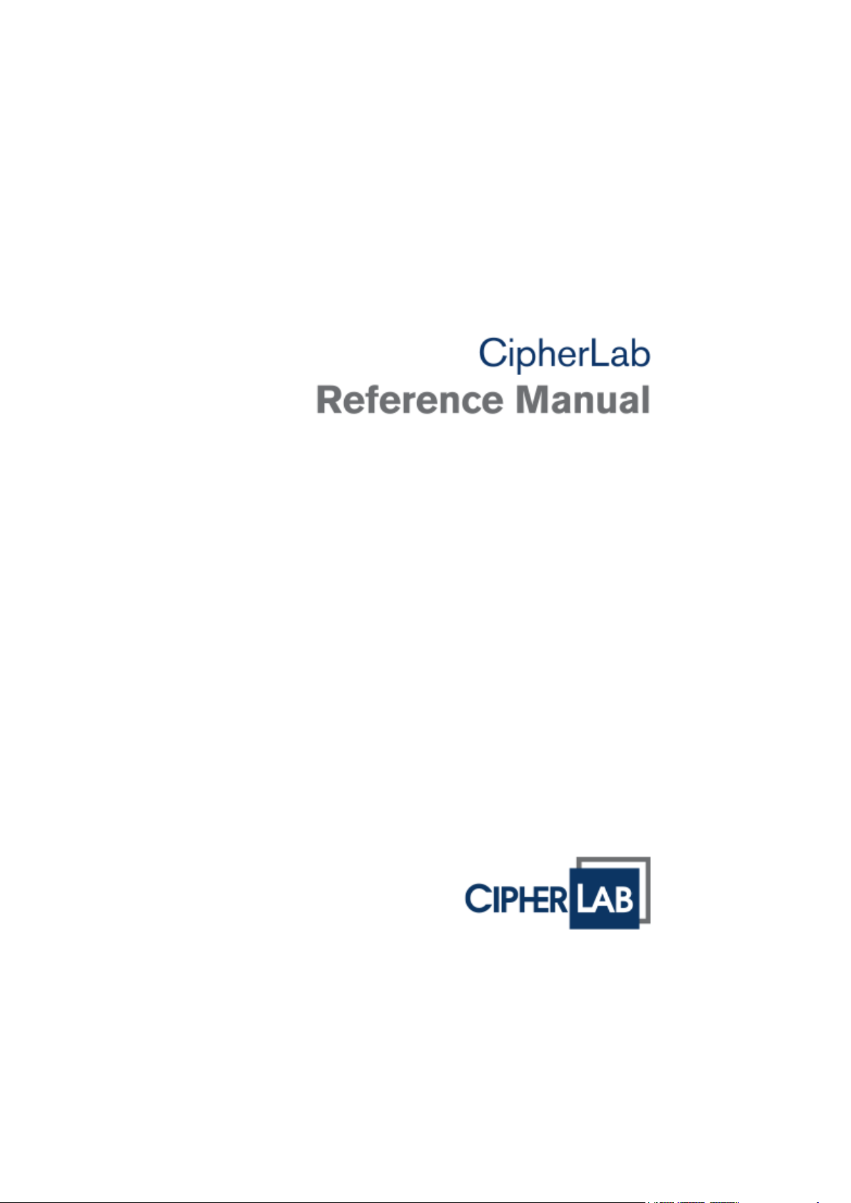
Figure 1: Overview
No. Description No. Description
1 Scanning window 2 LED for Good Read and battery charging
3 LED for wireless c om m unications 4 LCD screen
5 Keypad, 24 keys 6 Wristband
7 Communication/charging port 8 Battery compartment
2
Page 11

Introduction
FEATURES
INSIDE THE PACKAGE
ACCESSORIES
Ergonomic design — ruggedized yet streamlined, with wristband for secure hold
Built tough to survive drop test and sealed against moisture/dust to IP 52
Rich interface opt ions — USB
High capacity memory card (microSDHC) supported
Flexible wireless solutions — Bluetooth or 802.11b/g/n
FTP client support — 802.11b/g/n
Graphic monochrome LCD supports double-byte characters and bitmap graphics
Programmable feedback includes speaker, LED indicators and vibrator
Quick link to any backend database through MIRROR Emulator programs for
VT100/220 and IBM 5250 emulation
Easy customization of data collection applications through FORGE Application
Generator (AG) programs for preloaded AG Runtime, batch and WLAN versions
available
Programming support includes BASIC & C compilers
Accessories include pistol grip
The following items are included in the package. Save the box and packaging material for
future use in case you need to store or ship the Terminal.
8200 Series Terminal
Rechargeable Li-ion battery pack
Wristband
Standard USB cable
Universal power adaptor
Product CD
Quick Start Guide
Rich choices of optional accessories are available for you to enhance the total
performance of the Terminal.
Pistol Grip (detachable)
Protective Cover
Spare rechargeable Li-ion battery
3
Page 12
8200 Series Mobile Computer Reference Manual
GETTING STARTED
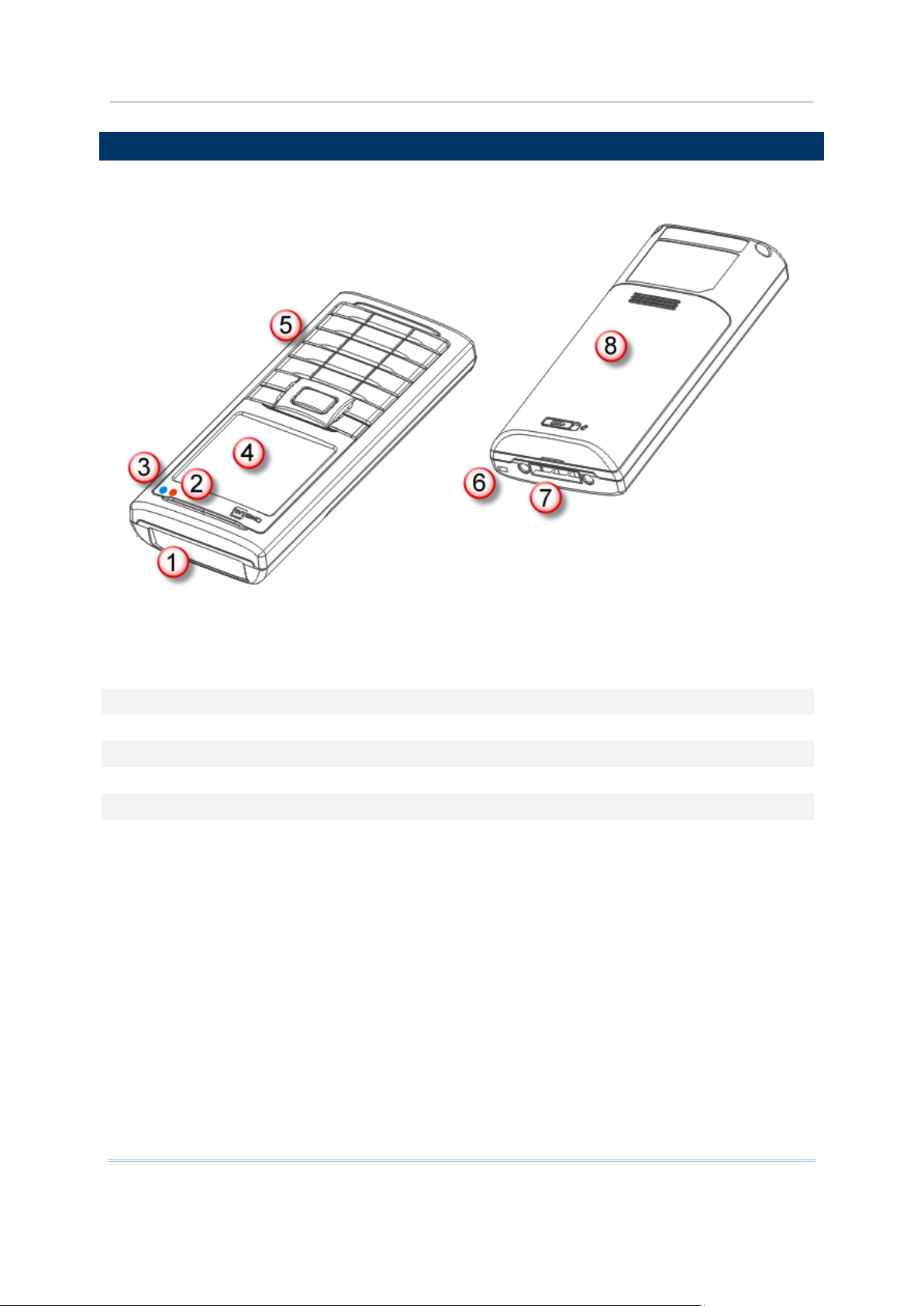
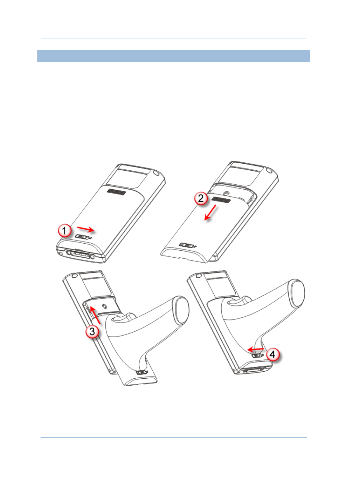
INSERTING BATTERY & MEMORY CARD
For shipping and storage purposes, save the Terminal and the main battery in sep arate
packages. This will keep both batteries in good condition for future use.
Note: Any improper handling may reduce the battery life.
1) Hold the Terminal still and slide the releas e latch to the ri ght to unlock the battery
cover.
2) Slide off the battery cover.
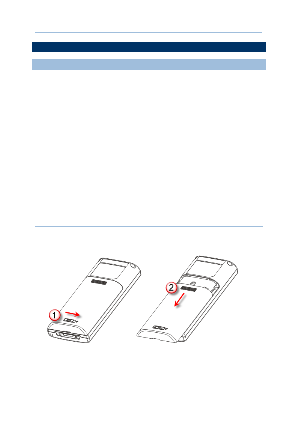
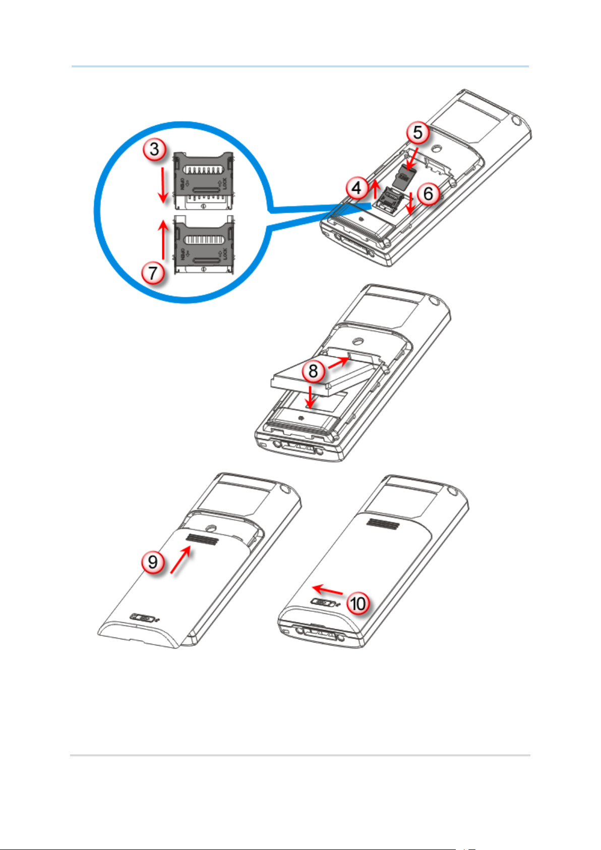
3) Use your finger to slide the locking plate towards its hinge to unlock the SD card
holder.
4) Flip up the SD card holder.
5) Insert your memory card (microSD or microSDHC) to the SD card holder.
6) Push the SD card holder down.
7) Slide the locking plate away from its hinge to secure the card.
8) Slide the battery pack into the battery compartment at a proper angle (30°~45°) so
that the metal contacts of the battery are met with the charging contacts inside the
compartment. Make sure that the battery is snugly fit into the compartment.
9) Replace the battery cover.
10) Slide the release latch to the left to lock it firmly.
Note: For a new battery, make sure it is fully charged before use. Always prepare a
spare battery pack, especially when you are on the road.
4
Page 13
Introduction
Unlock
Lock
Figure 2: Installing the Mai n Bat tery & Memory Card
5
Page 14
8200 Series Mobile Computer Reference Manual
INSTALLING PISTOL GRIP
This contoured pistol grip enables intuitive trigger-and-scan operation, which is very
helpful in scan intensive applications.
When a pistol grip is necessary, install it to the Terminal by following these steps:
1) Hold the Terminal still and slide the rel ease latch to the right to unlock the battery
cover.
2) Slide off the battery cover.
3) Insert the pistol grip into place (is like replacing the battery cover).
4) Slide the release latch to the left to lock it firmly, and turn on the Terminal to test the
trigger.
Figure 3: Installing the Pistol Grip
6
Page 15

Introduction
INITIAL CHARGING
SETTING LOCAL TIME
POWER MANAGEMENT
The main and backup batteries may not be charged to full for shipment. When you first
receive the package, you will need to charge the main battery to full before using the
Terminal. Instead of direct charging.
Note: Battery charging stops when the t emp e ra t u r e drops below 0°C or exceeds 40°C. It
is recommended to charge the battery at room temperature (18°C to 25°C) for
optimal performance. For initial charging, it takes approximately 2.5 hours to
charge the battery to full (from the adaptor).
Because the internal backup battery is constantly charged from the main battery, the
initial charging requires inserting the battery pack to the Terminal for ch arging. This will
have both the main and backup batteries charged at the same time. It takes at least 72
hours to fully charge the backup battery. However, it is not nec essa ry t o full y charg e th e
backup battery for the Terminal to work.
Note: In order to charge the backup battery to full, you must insert the main battery and
leave it for at least 72 hours, whether the Terminal is in use or not.
If you need to set your local ti me, go to System Menu | 2. S ettings | 1. Clock. Refer
to 3.2.1 Clock
.
For any port ab le device, p ower management is a critical is su e especially when you are on
the road. Below are some tips to help you save battery power.
Warning: Using backlight, wireless connectivity, and peripherals while on battery
power will substantially reduce battery power.
To speed up charging the Terminal, turn off the Terminal and use the
charging/communication cable.
Bring a second battery pack on the road.
Stop wireless connectivity, Bluetooth or 802.11b/g/n that is not in use.
Go t o System Menu | 2. Settings | 2. Backlight, and configure backlight period,
luminosity, as well as the shade effect. Refer to 3.2.2 Backlight
.
Go t o System Menu | 2. Settings | 4. Auto Off, and configure the amount of idle
time that must pass before the system will shut down automatically. Refer to
Auto Off.
3.2.4
7
Page 16

Page 17

This chapter explains the features and usage of the 8200 Series Terminal. The 8200
IN THIS CHAPTER
1.8 SD Card ..................................................................... 24
1.1 BATTERY
1.1.1 MAIN BATTERY
Chapter 1
USING 8200 TERMINAL
family in cludes :
8200 Batch type
8231 Bluetooth 2.1+EDR / BLE, Class 2; 802.11b/g/n
8260 Bluetooth 2.1+EDR, Class 2
1.1 Battery ........................................................................ 9
1.2 Memory ..................................................................... 11
1.3 Keypad ...................................................................... 12
1.4 LCD ........................................................................... 16
1.5 Notifications ............................................................... 17
1.6 Data Capture .............................................................. 19
1.7 Charging & Communications ......................................... 21
The Terminal is powered by a rechargeable 3.7 V/1200 mAh Li-ion battery pack. When
the Terminal is turn ed on, it takes approx. 2.5 hours to charge it to full from the power
adaptor (using cable) or approx. 4 hours from the USB cable (at 500 mA).
For power-saving purpose, always turn off the back light whil e working in a wel l-lit area.
When the backlight is on for extended periods of time, the main battery will become low
sooner than expected.
The smart battery icon on the LCD screen shows the status of power consumption. There
are two ways to monitor a low battery charge or discharged battery from the screen.
Examine the level of the 4-bar battery icon
Monitor voltage level (see 3.5 Power)
9
Page 18

8200 Series Mobile Computer Reference Manual
1.1.2 BACKUP BATTERY
1.1.3 CAUTION OF LOW BATTERY CHARGE
The backup battery on the main board takes charge when the main battery is removed or
drained out. When fully charged, the 3.0 V/18 mAh rechargeable Lithium button cell
helps retain data in SRAM and maintain the running of the real-time clock and cal endar
for at least 25 days wi thout the main battery. In the meantime, you ha ve to repl ace the
main battery as soon as possible. It takes at least 72 hours to fully charge the backup
battery. However, it is not necessary to fully charge the backup battery for the Terminal
to work.
Monitor voltage level (see 3.5 Power)
The battery p ack is the onl y power source for the Terminal to work. It also charges the
backup battery on the main board so that the data stored in SRAM can be retained
properly. Therefore, when the main battery charge goes low, you need to replace the
battery pack with a charged one or charge it as soon as possi ble. Mo st of all , you should
upload important data on a regular basis.
Warning: Data loss may occur with SRAM during low battery condition. Always save
data before running out of power or keep a fresh battery for replacement.
10
Page 19

Chapter 1 Using 8200 Terminal
1.2 MEMORY
1.2.1 READ-ONLY MEMORY (ROM)
1.2.2 RANDOM-ACCESS MEMORY (RAM)
1.2.3 SD CARD
The collected data can be sent back to a host computer immediately over wireless
networks, or stored in memory (SRAM) and upload later. The Terminal is equipped with a
calendar chip for accurate time/date logging. When the main battery is removed or
drained, the backup battery on the main board is to retain the contents of SRAM and
maintain the running of real-time clock and calendar for at leas t 25 days, on condition
that the backup battery has already been fully charged.
If you want to put away the Terminal for a couple of days, you should be aware that data
loss occurs when b oth t he main and ba ckup bat teries di scharg e compl etely. Th erefor e, it
is necessary to upload data and files before putting away the Terminal!
8 megabytes flash memory for storing core, OS, application programs, font, etc.
Options include 4 or 8 megabytes SRAM for storing data. Its contents will be retained by
the backup battery.
Secure Digital (SD) card is a flash memory data storage device. High capacity memory
card (microSDHC) is supported. Refer to Inserting Battery & Memory Card
insert the microSD or microSDHC card. For more details, refer to 1.8 SD Card.
Note: (1) When SD card is present, the card icon will appear on the screen and flash
while being accessed.
(2) For an SD card that has never been used on 8200, a messag e like “Found New
SD Card” wil l be displayed allowi ng users to scan the card f or memory check. If
the action is canceled then, memory check can still be performed via System
Menu —
3.8 SD Card Menu.
for how to
11
Page 20
8200 Series Mobile Computer Reference Manual
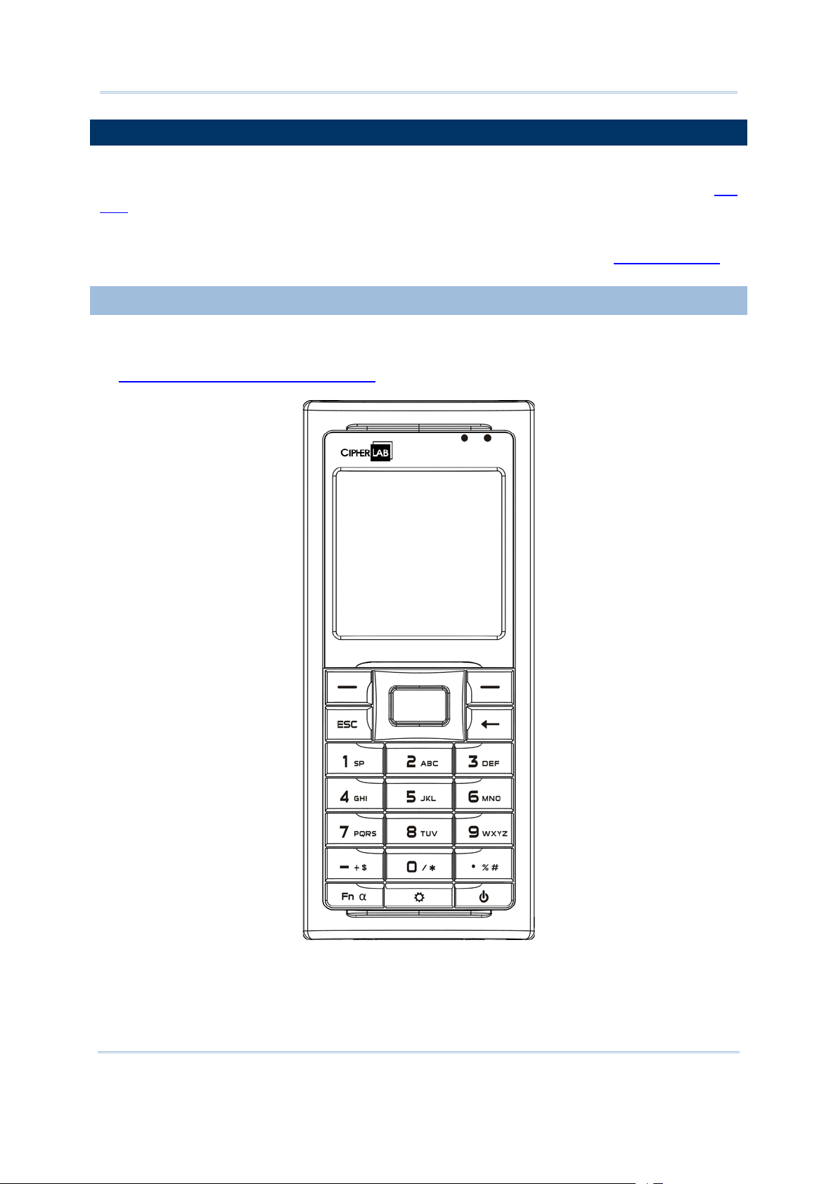
1.3 KEYPAD
1.3.1 24-KEY LAYOUT
The Terminal is equipped with a keypad of 24 ke ys for system s etup, user en try and so
on. The keypad comes with programmable LED backlight, like the screen. Refer to
LCD for screen & backlight settings.
Silicon rubber has been chosen for their durability and prompt feedback. The key click
can be configured through programming or via System Menu. Refer to 3.2.6 Key Click
1.4
.
The layout of the 24-key keypad is similar to that of a telephone, which includes
alphanumeric, navigation and function keys, as well as assorted characters. Refer
to Appendix III — Key Reference Table
for color-coded keys.
Figure 4: 24-key Layout
12
Page 21

Chapter 1 Using 8200 Terminal
This alph anumeric keypad i s set to n umeri c mode by defaul t. The [Fn α] key se rves as a
Status Icon
Function/Alpha Key
Input Mode
toggle among numeric, alpha (lower-case alphabetic), and ALPHA (upper-case alphabetic)
input modes, as well as function mode.
Note: It is not necessary to hold down the [Fn α] key.
The associated icon will appear on the lower-left corn er of the screen in a sequ ence as
shown below.
(none) N/A Numbers
A Press [Fn α] one time Upper-case alphabetic
a Press [Fn α] two times Lower-case alphabetic
F Press [Fn α] three times Function Mode
When in alpha mode, it takes turns to show alphabets and number when you keep
pressing the same key; each press must not exceed one second. For example, keep
pressing the number key [2], it will take turns to show “A”, “B”, “C” or “2” for upper-case,
and “a”, “b”, “c” or “2” for lower-case.
When you first press the number key [2], it will produce the letter “A” or “a”.
When you press the number key [2] twice (the time interval must not exceed one
second), it will produce the letter “B” or “b”.
When you press the number key [2] three times (the time interval between each
press must not exceed one second), it will produce the letter “C” or “c”.
Wh en you p ress t he n u mber k ey [2 ] f our t i mes (th e ti me in terval b etween ea ch p res s
must not exceed one second), it will produce the number “2”.
In order to get the desired charact er, you will need to p ress the same key , one to four
times (the ti me interval between each press must not exc eed one sec ond). Only when
you stop pressing the same key for longer than one second or you press another key, will
the system send the real key code to the application program.
When in function mode, the [ Fn α] key works with a number key. Pr ess the [Fn α] key
three times , and its associated icon F wil l be displayed on the screen. Press the secon d
key, say [5], to complete the key combination and access the function [F5]. Press [Fn α]
again and the icon F will go off.
13
Page 22
8200 Series Mobile Computer Reference Manual
Below briefly describes the functions of common keys on the Terminal.
SCAN
to trigger the scan engine so that it
ENTER
friendly and convenient for either
. Normally, it is used for command execution or input
ESC (Escape)
key. Normally, it is used to stop and exit the current
Navigation Pad
used to move the cursor left, up, down, or
luminosity and contrast of the screen
Backspace
by default. If this key is being held down for more than one second,
clear
Function/Alpha Key
(A~Z)
Icon
Description
, indicating it is set to
, indicating it is set to
set to the
To get the value of another key combination modified by the function key, keep
The yellow key is used to work as the ENTER key by default.
When the reader function is enabled, this yellow key is set
can read a barcode.
The two keys on each upper side of the SCAN key are userright-handed or left-handed operator
confirmation.
This key is on the left lower side of the SCAN
operation.
The 4-way navigation pad around the SCAN key is
right.
While pressing [ ], they can be used to adjust the
backlight.
This key is Backspace
a
This key is a modi fi e r ke y that requi res p ressing a second key to get the yellow-coded let ter
or symbol printed above the second key, or the function (F0~F9) of the secon d key.
A This icon appears when you press the [Fn α] key one time
a This icon appears when you press the [Fn α] key two times
F This icon appears when you press t he [Fn α] key three times, indicating it is
code will be sent.
alphabetic mode for typing upper-case alphabetic letters.
alphabetic mode f or typing lower-case alphabetic letters.
function mode. Then, press another key ([0] ~ [9]) to get the desired function.
pressing another key ([ 0] ~ [9]) to produce the result.
To exit the function mode, press [Fn α] again and the icon will go off.
14
Page 23

Chapter 1 Using 8200 Terminal
Backlight Configuration Key
This key is used to turn ON/OFF the backlight of the LCD and keypad. Also, while pressing [ ]
,
Key
Description
Power Key
In order to prevent an accidental press of the POWER key, you need to hold down this key for
the navigation k e ys can be used to adjust the luminosity and contrast of the screen backlight.
[ ] + [Right] Press these keys at the same time to increase the contrast.
[ ] + [Left] Press these keys at the same time to decr ea s e th e contrast.
[ ] + [Up] Press these keys at the same time to increase the luminosity.
[ ] + [Down] Press these keys at the same time to decrease the luminosity.
approximately 1.5 seconds to turn ON/OFF the Terminal.
Note: (1) Functionality of keys is application-dependent. The system will send the
associated key code to the application program, and it is up to the application
program to interpret the key code.
(2) When a status icon appears on the screen, it indicates a certain mode is
activated and it is not necessary to hold down the modifier key.
15
Page 24
8200 Series Mobile Computer Reference Manual
1.4 LCD
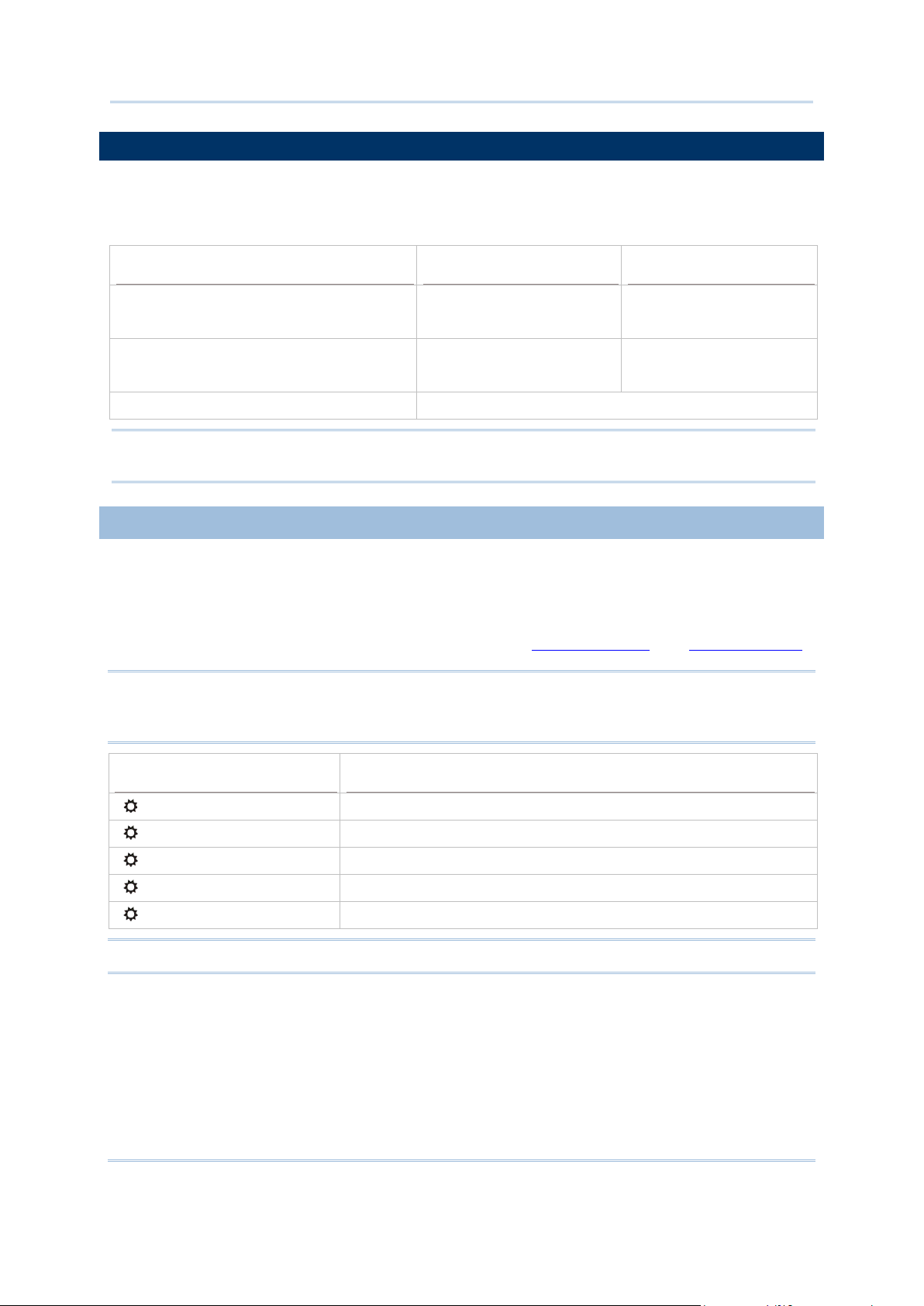
Options
Font Size (pixels)
Characters by lines
1.4.1 ADJUSTING THE BACKLIGHT
Key Combination
Action
The Terminal comes with a FSTN graphic LCD, 160 by 160 pixels resolutions, which can
be programmed t o display text or graphi cs, such as specific font and company logo, to
meet varying application needs.
English font Font size 6×8 (pixels)
Font size 8×16 (pixels)
Chinese font Font size 12×12 (pixels)
Font size 16×16 (pixels)
Other language fonts, company log o… Programmable
26 characters by 18 lines
20 characters by 9 lines
13 characters by 12 lines
10 characters by 9 lines
Note: The bottom line (ICON_ZONE) is reserved to display status icons, such as the
battery icon.
The backl ight of screen a nd keypad helps ea se reading under d im environments. It can
be turned on an d a d j u sted decrea singly or increasingly by the following key combinati on s.
Keep pressing the key combination until the luminosity or contrast is decreased or
increased to a d esired l evel. Alt ernativel y, the luminosity and contrast can be con figured
through programming or via System Menu. Refer to 3.2.2 Backlight and 3.2.3 Contrast
Note: Using backlight while on battery power will substantially reduce battery power. We
suggest that you dim the backlight while working in a well-lit area or have it set to
be automatically turned off when not in use.
.
[ ] Toggle ON/OFF the backlight
[ ] + [Up] Turn ON the backlight and increase the luminosity of LCD
[ ] + [Down] Turn ON the backlight and decrease the luminosity of LCD
[ ] + [Right] Turn ON the backlight and increase the contrast of LCD
[ ] + [Left] Turn ON the backlight and decrease the contrast of LCD
Note: Hold down the first key, and keep pressing the second key for adjustment.
16
Page 25
Chapter 1 Using 8200 Terminal
1.5 NOTIFICATIONS
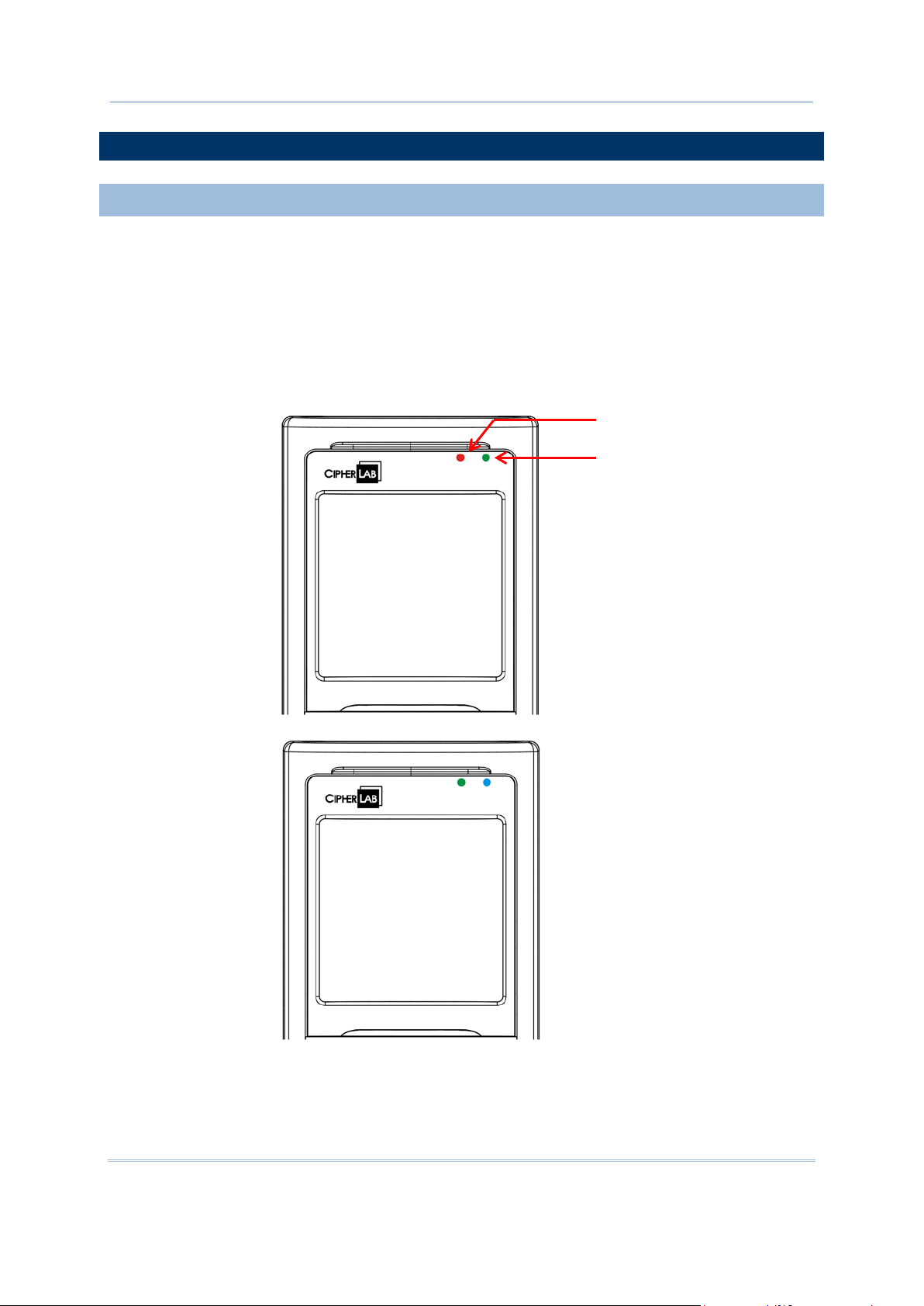
1.5.1 STATUS LED
LED1
LED2
There are tw o dual-color LED indicators above the screen. B oth can be progra mmed to
provide in format i on that helps diagnosing. For exam pl e, i f you are u si ng AG runtime, you
will be informed of the scanning result immediately. LED1 is used for "Good Read" and
will become solid green upon reading a barcode successfully.
LED1 is used to provide information on the charging status and barcode decoding.
LED2 is use d to provide informat ion on wireless communications.
Figure 5: LED Indicators
17
Page 26

8200 Series Mobile Computer Reference Manual
LED1: Red/Green
Red
Green
Solid green for Good Read by
Battery
LED2: Blue/Green
Blue
Green
Flashing blue, quickly: Waiting for
, quickly: Waiting
1.5.2 AUDIO
1.5.3 VIBRATOR
User Power ON User definable User definable
default
Power Off,
Charging
Charging Error System default
System default
Flashing red: Charging
Flashing red and green: Charging error occu rs
System default
Flashing green: Cha r gin g done
Bluetooth System default
---
connection or con necting
Flashing blue, s lowly: Connected
Wi-Fi --- System default
Flashing green
for connection or connecting
Flashing green, slowly:
Connected
The Terminal has a mono or stereo speaker at the bottom, whi ch can be programmed fo r
status feedback. It is used to play soun ds for events i n the programs, or play audio files
such as .WAV files. Its volume can be configured throug h programming o r via System
Menu. Refer to 3.2.7 Speaker Volume
. In particular, its frequency and duration are
software programmable for Good Read in the provided terminal emulation programs.
The Terminal is integrated with a vibrator, which can be p rog ram m ed f or st atu s f eedb ack .
It can be helpful when working in noisy environments. In particular, the vibrator is
software programmable for Good Read in the provided terminal emulation pro grams.
18
Page 27

Chapter 1 Using 8200 Terminal
1.6 DATA CAPTURE
Symbologies Supported (Default Setting: Enable/Disable)
CCD/Laser
2D
A wide variety of scan engines is available for delivering flexibility to meet different
requirements. Depending on the scan engine integrated, the Terminal is capable of
scanning barcodes of a number of symbologies that are enabled by default while running
the preloaded AG runtime. Refer to 3.3.1 Reader
for functional test.
If you need to scan barcodes that are encoded in a symbology, which is disabled by
default in AG runtime, FORGE Applicat ion Gene rator (ForgeAG.exe) allows configuring
symbology settings, as well as reader settings. First, enable the desired symbologies, and
then, download the application settings to the Terminal.
Note: For details on configuring reader and symbology settings, please refer to the
documentation of the software you use.
Varying by the scan engine installed, the supported sym bologies are listed below.
1D CCD scan engine
1D Lase r scan en g i n e
2D scan engine
Note: In AG or CipherNet runtime, not all of the symbologies are enabled by default.
Instead of running a ny of them , you ca n devel op your ow n appli cations to control
the scan engine for data collection.
Codabar Enabled Enabled
Code 11 Disabled
Code 93 Enabled Enabled
Composite
Code
MSI Disabled Disabled
Plessey Disabled
Postal Codes Enabled
Telepen Disabled
Code 128 Code 128 Enabled Enabled
Code 2 of 5 Industrial 25 (Discrete 25) Enabled Enabled
CC-A/B Disabled
CC-C Disabled
TCIF Linked Code 39 Enabled
GS1-128 (EAN-128) Enabled Enabled
ISBT 128 Enabled Enabled
Interleaved 25 Enabled Enabled
Matrix 25 Disabled Disabled
19
Page 28

8200 Series Mobile Computer Reference Manual
Chinese 25 Disabled
Coop 25 Disabled
Code 3 of 9 Code 39 Enabled Enabled
Trioptic Code 39 Disabled
Italian Pharm a c ode (Code 32) Disabled Disabled
French Pharmacode Disabled
EAN/UPC EAN-8 Enabled Enabled
EAN-8 Addon 2 Disabled Disabled
EAN-8 Addon 5 Disabled Disabled
EAN-13 Enabled Enabled
EAN-13 & UPC-A Addon 2 Disabled Disabled
EAN-13 & UPC-A Addon 5 Disabled Disabled
Bookland EAN (ISBN) Disabled Disabled
UPC-E0 Enabled Enabled
UPC-E1 Disabled Disabled
UPC-E Addon 2 Disabled Disabled
UPC-E Addon 5 Disabled Disabled
GS1 DataBar
(RSS)
2D
Symbologies
UPC-A Enabled Enabled
GS1 DataBar Omnidirectional (RSS-14) Disabled Enabled
GS1 DataBar Truncated Disabled Enabled
GS1 DataBar Stacked Disabled Enabled
GS1 DataBar Stacked Omnidirectional Disabled Enabled
GS1 DataBar Limited (RS S Limited) Disabled Enabled
GS1 DataBar Expanded (RSS Ex pa nded) Disabled Enabled
GS1 DataBar Expanded Stacked Disabled Enabled
PDF417 Enabled
MicroPDF417 Enabled
Data Matrix Enabled
Maxicode Enabled
QR Code Enabled
20
Page 29

Chapter 1 Using 8200 Terminal
1.7 CHARGING & COMMUNICATIONS
USB Interface Cable
Task
USB Cable
Application Generator software, you
may use a download utility to receive data on your computer; otherwise,
If using FORGE Application Generator software,
you may use a download utility to receive data on your computer;
Normally, the Terminal ships with a USB cable for charging and communications.
If y ou are using USB Virtual COM for th e first time, you mu st install its dri ver from
the CD-ROM. Driver version 5.3 or later is required. Please remove older versions!
The virtual COM port will not be assigned until the USB port is in use.
If you are using USB Virtual COM_CDC for the first time, you must install its driver
from the CD-ROM. USB CDC driver installer is available in the “Windows” folder,
which will copy a vendor-supplied INF file to Windows.
For Standard USB cable, it will release COM port in the following conditions:
(i) Detach the cable from the Terminal directly.
(ii) The Terminal is turned off.
(iii) No application is runnin g on the Terminal, or COM port is shut down.
Charging USB direct charging
500 mA: USB icon
100 mA: Highlighted USB icon
0 mA: Disable charging for 8200
5 V charging from the adaptor (Plu g ic on)
Communications USB Virtual COM — If using FORGE
run HyperTerminal.ex e to rec eive data directly.
USB HID — Run a text editor on your computer to receive data dir e ctly.
USB Virtual COM_CDC —
otherwise, run HyperTer minal.exe to receive data direc tly .
21
Page 30

8200 Series Mobile Computer Reference Manual
Note: Battery charging stops w h en t h e temperatur e drops bel ow 0 °C or exc e ed s 4 0°C. It
1.7.1 INTERFACE CABLE OPTIONS
Universal Power Adaptor
Push
is recommended to charge the battery at room temperature (18°C to 25°C) for
optimal performance.
For charging via the USB cable, the standard charging current is 500 mA. However, we
recommend you to connect the power adaptor to speed up charging the battery.
If you connect the Terminal to a USB hub, the charging current may be insufficient.
In that case, change the charging current to 100 mA after connecting the USB cable.
It will take a longer time to charge to full. Refer to 3.2.9 USB Charge Current
.
& release
22
Page 31

Chapter 1 Using 8200 Terminal
Figure 6: Using USB/RS-232 cable
Warning: The Terminal is not allowed to function when it is solely on USB power and
without a battery loaded. It will display a warning message “Battery
Missing” along with an audible alert. In that case, you should install the
battery before restarting.
23
Page 32

8200 Series Mobile Computer Reference Manual
1.8 SD CARD
1.8.1 FILE SYSTEM
Card Capacity
FAT Format
Sectors per Cluster
1.8.2 DIRECTORY
Reserved Directory
Related Application or Function
Remark
Store programs to this folder so that you can
Store DAT and DBF files that are created and
SD card can be accessed directly by using the provided functions in user application. Yet,
when 8200 is equipped with SD card and connected to your computer via the USB cable,
it can be treated as a removable disk (USB mass storage device) as long as it is
configured properly through programming or via System Menu | 8. Next Page | 1. SD
Card Menu | 1. Run A s USB Disk. Refer to 3.8 SD Card Menu
Note: While running B AS IC a pp l ication, th e si z e of D AT files on SD ca rd can be cal ibrated.
Go to System Menu | 8. Next Page | 1. SD C ard Menu | 2. Ac cess SD Card |
4. Check File Size
to refresh the size of “A:\BASICRUN\TXACTn.DAT” (n=1~6).
.
For 8200 Seri es, i t support s FAT12/FAT16/FAT32 and allows formatting the card through
C programming or via System Menu | 8. Next Page | 1. SD C ard Menu | 2. Access
SD Card. Based on the capacity of the card, it will automatically decide the FAT format:
≦ 32 MB
≦ 1 GB
≦ 2 GB
≦ 8 GB
FAT12 32
FAT16 32
FAT16 64
FAT32 8
Unlike the file system on SRAM, the file system on SD card supports hierarchical tree
directory structure and all ows creating sub-directories. Several directories are reserv ed
for particular use.
\Program
\BasicRun BASIC Runtime
System Menu | Load Program
Program Manager | Download
Program Manager | Activate
Kernel Menu | Kernel Update
UPDATE_BASIC()
download them to 8200:
C program — *.SHX
BASIC program — *.INI and *.SYN
accessed in BA SIC runtime to this folder .
Their permanent filenames are as follows:
24
Page 33

Chapter 1 Using 8200 Terminal
System Default
System Default
System Default
System Default
System Default
DAT Filename
DAT file #1 TXACT1.DAT
DAT file #2 TXACT2.DAT
DAT file #3 TXACT3.DAT
DAT file #4 TXACT4.DAT
DAT file #5 TXACT5.DAT
DAT file #6 TXACT6.DAT
DBF Filename
DBF file #1 Record file F1.DB0
F1.DB1
Index
Index file #1 F1.DB2
Index file #2 F1.DB3
Index file #3 F1.DB4
DBF file #2 Record file F2.DB0
F2.DB1
Index
Index file #1 F2.DB2
Index file #2 F2.DB3
Index file #3 F2.DB4
DBF file #3 Record file F3.DB0
F3.DB1
Index
Index file #1 F3.DB2
Index file #2 F3.DB3
Index file #3 F3.DB4
DBF file #4 Record file F4.DB0
F4.DB1
Index
Index file #1 F4.DB2
Index file #2 F4.DB3
Index file #3 F4.DB4
DBF file #5 Record file F5.DB0
F5.DB1
Index
Index file #1 F5.DB2
Index file #2 F5.DB3
Index file #3 F5.DB4
25
Page 34

8200 Series Mobile Computer Reference Manual
\AG\DBF
Store DAT, DBF, and Lookup files that are
created and/or accessed in Application
1.8.3 FILE NAME
\AG\DAT
\AG\EXPORT
\AG\IMPORT
Application Generator (a.k.a. AG)
Generator to this f older.
A file name must follow 8.3 format (= short filenames) — at most 8 characters for
filename, an d at most three cha racters for fil ename extension. Th e following ch aracters
are unacceptable: “ * + , : ; < = > ? | [ ]
On 8200 Series, it can only display a filename of 1 ~ 8 characters ( the nu ll chara cter
not included), and filename extension will be displayed if provided. If a file name
specified is longer than eight characters, it will be truncated to eight characters.
Long filen ames, at mos t 255 cha racters , are all owed when u sing 8200 equipped with
SD card as a mass storage device. For example, you may have a filename
“123456789.txt” created from your computer. However, when the same file is directly
accessed on 8200, the filename will be truncated to “123456~1.txt”.
If a file name is specified other i n ASCII characters, i n order for 8200 to display it
correctly, you may need to download a matching font file to 8200 first.
The file name is not case-sensitive.
26
Page 35

This chapter mainly describes the software inside the Terminal. It consists of three
Chapter 2
LEARNING SOFTWARE ARCHITECTURE
modules — Kernel, System, and Application; each has a function menu.
When a menu is displayed, you may select an item by either of the following ways:
Press the arrow keys [Up] and [Down] to move the highlight bar.
Press the number key that corresponds to the item number.
Follow the on-screen instructions to change a specific setting, or press [ESC] to
return to a previous page or menu.
On each screen, the bottom line displays status icons, such as:
The 4-bar battery icon indicates the current power status.
The status icon of input mode or function mode is controlled by the [Fn α] key.
27
Page 36

8200 Series Mobile Computer Reference Manual
IN THIS CHAPTER
2.2 System Configuration & Core ........................................ 30
Figure 7: Software Architecture
2.1 Application Module ...................................................... 29
28
Page 37

Chapter 2 Learning Software Architecture
2.1 APPLICATION MODULE
2.1.1 FORGE APPLICATION GENERATOR (AG)
Batch AG
WLAN AG
Application Generator
AG Runtime
Companion Tool on PC End
The Terminal ships with software package on the CD-ROM. It includes FORGE
Application Generator (batch and WLAN versions), MIRRO R Emulator (VT and 5250
versions), download utilities, etc.
For easy development of applications, the Terminal is preloaded with AG runtime. When
you turn on the Terminal, it displays the Main Menu of AG application, as shown below.
Note: Batch AG supports automatically uploading data to a host computer when the
upload interface is properly configured. Once the Terminal is connected via the
RS-232 or USB Virtual COM cable, there will be a moving hourglass icon displayed
on the upper-right corner of the scre en, indicating the Terminal i s ready for aut o
upload.
Before usin g the Terminal to collect data, you need to configure the application with the
companion tool on your computer. This time-saving development tool helps create
application templates on your computer.
For details on the AG application, please refer to separate user manual.
Batch AG U8200.SHX ForgeAG.exe
WLAN AG WU8200.SHX AG8200WLAN.exe
Note: FORGE Application Generator (AG) software package includes
(1) a companion tool for quickly developing your application — Batch or WLAN AG;
(2) several download utilities to make it versatile in use.
29
Page 38

8200 Series Mobile Computer Reference Manual
2.1.2 MIRROR EMULATOR (CIPHERNET)
Terminal Emulation
CipherNet Runtime
Companion Tool on PC End
2.1.3 USER PROGRAM
2.2 SYSTEM CONFIGURATION & CORE
The Terminal supports VT100/220 and IBM 5250 terminal emulation for accessing a
backend database. In ste ad of using FORGE A pplication Generator , you ma y dow nload
the terminal emulation program, i.e. CipherNet Runtime, to the Terminal. Refer to
Load Program. Then, run individual companion tool on your computer.
For details on the MIRROR Emulator application, please refer to separate user manuals.
VT100/220 82xx-VT.SHX CipherNet-VT.exe
IBM 5250 82xx-5250.SHX CipherNet-5250.exe
3.6
You may need to develop your own application program. For developing custom
applications, CipherLab provides BASIC and C compilers through licensing. For detailed
information, please contact your sales representative.
30
Page 39

Chapter 2 Learning Software Architecture
For managing system configurations an d multiple programs, ea ch Terminal comes with
2.2.1 SYSTEM MENU
2.2.2 KERNEL
2.2.3 PROGRAM MANAGER
System Menu, Program Manager, and Kernel Menu. Refer to t he followi ng chapters
on how to configure the 8200 Series Terminal, regarding system configurations and
program download.
System Men u is bundled with BASIC Runtime or user programs that are written in “C”. It
is provided for system configuration, functionality testing, downloading font file and
program.
Kernel i s the innerm ost core of t he OS. It p rovides se rvices for u pdating th e kernel and
bootloader, and repairing the system.
Program Man ager is part of the kernel. You may download as many as seven application
programs.
31
Page 40

8200 Series Mobile Computer Reference Manual
32
Page 41

System Menu is gener ated by a p owerful utility, wh ich off ers an in terface fo r engin eers
How to access System Menu?
Chapter 3
SYSTEM MENU
(programmers or system integrator) to view system information, change the
configuration parameters, download programs and run diagnostics.
This menu i s designed for engineeri ng tests and maintenance ONLY. For this reason, it
provides password protection to prevent unauthorized users from accidentally changing
system settings.
Warning! S ystem Menu is NOT fo r the use of any end users. The system p assword
helps ensure system safety and integrity.
5) Turn off the Terminal.
6) Press [7] + [9] + [Power].
33
Page 42

8200 Series Mobile Computer Reference Manual
IN THIS CHAPTER
3.1 Information ................................................................ 34
錯誤! 尚未定義書籤。
3.12 Wi-Fi Menu ............................................................... 60
3.1 INFORMATION
System Menu | 1. Information
scan engine
3.2 Settings ..................................................................... 36
3.3 Tests ......................................................................... 40
3.4 Memory ..................................................................... 42
3.5 Power ........................................................................ 43
3.6 Load Program ............................................................. 44
3.7 DoFTP Menu ............................................................... 47
3.8 SD Card Menu ............................................................ 49
3.10 Serial PPP Menu ................................
3.11 Bluetooth Menu ......................................................... 51
Here provides important system information to help d iagnose the system.
H/W Hardware version
S/N A serial number assigned to th e Terminal
M/D Manufacturing date
KNL Kernel version
LIB
BSC
USR Application program version
DEV 4-digit code for optional hardware configura tions
C library version
BASIC Run-time version, if a BASIC ap plication is downloaded
For example, 2800 indicates the Terminal is equipped with Laser
and combo module for wir ele s s connectivity (Bluetooth + 802.11b/g/n).
34
Page 43

Chapter 3 System Menu
3.1.1 UNDERSTANDING DEVICE CODE
Device Code
Modular Component
Types
1st digit Reader module 0= none
1= CCD scan engine
2= Laser scan engine
3= 2D scan engine
2nd digit Wireless module 0= none
5= Bluetooth only
8= Bluetooth + 802.11b/g/n
3rd digit Reserved 0
4th digit Reserved 0
(8200)
(8260)
(8231)
35
Page 44

8200 Series Mobile Computer Reference Manual
3.2 SETTINGS
System Settings
Default Values
3.2.1 CLOCK
3.2.2 BACKLIGHT
You can change the default settings here.
Clock Current time
Backlight 20 seconds at level 2, backlight shade enabled
Contrast Level 4
Auto Off 10 minutes
Power On Options Program Resume
Key Click Tone 2
Speaker Volume High volume level
USB VCOM No. Fixed
USB Charge Current 500 mA
System Password Open access
Font System font
Default Set (=Reset to Default) Load factory settings
Reset Reader Restore default reader settings
Upgrade Reader FW Upgrade 2D reader firmware (For maintenance use only)
Set date and time for Real Time Clock. Enter two digits for the year, e.g. 04 for 2004.
Set the backlight duration for the keypad and LCD.
Enter a value between 0 and 9999 (second).
Press the arrow keys [Up] and [Down] to adjust the backlight level (4 levels).
Press the [Left] key to adjust the shade effect.
36
Page 45

Chapter 3 System Menu
3.2.3 CONTRAST
3.2.4 AUTO OFF
3.2.5 POWER ON (& WAKEUP EVENT) OPTIONS
Power On Options
, and then
rogram
WakeUp Events
as a
the alarm time is up. Alarm can be set up
Set the contrast level for the LCD.
Press the arrow keys [Up] and [Down] to adjust the contrast level.
The Terminal will be turned off automatically when no operation is taking place during a
specified period of time. Enter a value between 0 and 999 (minute).
Note: To disable this function, enter 0.
Set the startup screen once the Terminal is turned on, and specify which events will wake
up the Terminal:
Press the arrow keys [Up] and [Down] to select “Program Resume” or “Program Restart”
press [ENTER].
Program Resume: When selected, the Terminal will start from the last session of p
before it is turn ed off.
Program Restart: When selected, the Terminal will start from the first session of the pr og r am.
The specified events can wake up the Terminal when the conditions are met. Press the arrow keys
[Up] and [Down] to select a specific event, and press [ENT ER] to determine when it is treated
wake-up event or not.
PwrKey: If yes, it will wake up the Terminal upon pressing the Power key.
USB: If yes, it will wake up the Terminal upon connecting the USB cable.
Charged: If yes, it will wake up the Terminal upon completion of charging.
Alarm: If yes, it will wake up the Terminal upon
through program m ing only.
37
Page 46

8200 Series Mobile Computer Reference Manual
3.2.6 KEY CLICK
3.2.7 SPEAKER VOLUME
3.2.8 USB VCOM NO
3.2.9 USB CHARGE CURRENT
3.2.10 FONT
The system will produce an audible signal when any key on the keyp ad is pressed . The
current value is highlighted. Select a desired tone for the speaker or mute it.
Set the speaker volume.
Pr ess the arrow keys [Up] and [Down] to adjust the volume level ( 3 levels) or mu te
it.
By default, it i s set t o use one virtual COM port for all (=FIXED), regardl ess of h ow man y
8200 Terminals are connected to PC when USB Virtual COM is in use. This setting
requires you to conne c t one 8200 at a ti me, and will facilitate configuring a great amount
of 8200 Terminals via the same virtual COM port (for administrators’ or factory use). If
necessary, you can have it set to use variable virtual COM port (=Change by Serial
Number), which will vary by the serial number of each different 8200.
Press the arrow keys [Up] and [Down] to select between “Fixed” and “Change by
Serial Number”.
By default, the USB charging current is set to 500 mA. For direct charging via the USB
cable without supplying a power adaptor, the standard charging current is 500 mA . I f you
connect the Terminal to a USB hub, the charging current may be insufficient. In that case,
change the charging current to 100 mA after connecting the USB cable. It will take a
longer time to charge to full.
Press the arrow keys [Up] and [Down] to select between “500 mA” and “100 mA”.
To disable charging for 8200, select “0 mA”.
Note: (1) USB direct charging, 500 mA: USB icon
(2) USB direct charging, 100 mA: Highlighted USB icon
(3) 5V charging from the adaptor: Plug icon
Font version information can be viewed here. It displays System Font if there is no
custom font file. If a multi-language font file is downloaded, you will be able to select a
font from the list.
38
Page 47

Chapter 3 System Menu
3.2.11 SYSTEM PASSWORD
3.2.12 DEFAULT SET
3.2.13 RESET READER
3.2.14 UPGRADE READER FW
Set a password to control user access to System Menu, Program Manager and Kernel
Menu. The password can be up to eight alphanumeric characters.
Note: The password is case-sensitive. To disable a previous password, enter blank on
the "Input new password" and "Verify password" screens.
Reset system settings to the default values, except for the re a der settings.
Reset reader settings to the default values.
Upgrade 2D reader firmware if necessary.
39
Page 48

8200 Series Mobile Computer Reference Manual
3.3 TESTS
3.3.1 READER
3.3.2 SPEAKER
3.3.3 LCD & LED
3.3.4 KEYBOARD
3.3.5 MEMORY
Here provides functional tests for key parts.
Test the re ading p erformance of the sc anner. The supported symbologies depend on the
scan engine you use. Refer to 1.6 Data Capture
default. For symbologies that are disabled by default, they must be enabled through
programming.
for symbologies that are enabled by
Press [SCAN] to start. To stop and exit the test, press any key.
Test the speaker with different volume levels.
To stop and exit the test, press any key.
Test the LCD display and LED indicators.
To stop and exit the test, press any key.
Test the rubb er ke ys. Press any ke y an d its corr esp on d i n g ch aract er will be shown on the
screen.
To stop and exit the test, press [ESC].
Test the data memory (SRAM), and the results will be shown on the screen.
To stop and exit the test, press [ESC].
Warning! The contents of the data memory (SRAM) will be wiped out after test.
40
Page 49

Chapter 3 System Menu
3.3.6 ECHO TEST
Interface
Description
Test Utility
cho test is to verify connectivity via the USB cable
works as a generic
works as an input device;
pe and Caps Lock status for running a
Any text editor for
works as a
3.3.7 VIBRATOR
After a physical connection is established properly, run a test utility on your computer
and start the test on your Terminal. Select a desired baud rate if necessary.
To stop and exit the test, press [ESC].
USB This e
between the Terminal and a host computer.
USB VCOM Echo — The Terminal
USB device.
USB HID — The Terminal
select keyboard ty
test.
USB VCOM_CDC Echo — The Terminal
generic USB device.
Test the vibrator.
To stop and exit the test, press [ESC].
EchoTest.exe for
Virtual COM
HID
EchoTest.exe for
Virtual COM
41
Page 50

8200 Series Mobile Computer Reference Manual
3.4 MEMORY
3.4.1 SIZE INFORMATION
3.4.2 INITIALIZE
Here p rovides information and initialization function of the memory.
RAM — onboard SRAM for data memory
Flash — program memory
Initialize the data memory.
Warning! The contents of the data memory (SRAM) will be wiped out after memory
initialization.
42
Page 51

Chapter 3 System Menu
3.5 POWER
Main (battery)
Backup (battery)
Here shows current voltage consumption.
It shows dynamic status of the battery pack, which is used as the main power source.
It shows dynamic status of the button cell, which is used to retain data in SRAM.
Warning! A lways examine the b attery icon on the d evice screen so tha t you will be
alerted for a low battery condition.
43
Page 52

8200 Series Mobile Computer Reference Manual
3.6 LOAD PROGRAM
.SHX Program
Download one of the following C program files and/or font file:
Here you can access the Load Program service provided by the kernel. Because the
kernel will take over the job, you will not be able to return to System Menu by p ressi ng
[ESC]. After downloading, restart the Terminal to activate the new program. Refer
to Appendix I Download Utility
Note: The Terminal will stay in download mode for approximately 30 seconds.
Program File
Font File Refer to the Font Files folder on CD -ROM.
.
AG Runtime:
CipherNet Runtime:
BASIC Runtime
User program
Note
U8200.shx (Batch AG)
WU8200.shx (WLAN AG)
82xx-5250.shx (CipherNet-5250)
82xx-VT.shx (CipherNet-VT)
:
B8200.shx
If you have downloaded a BASIC Runtime program, the next time you enter the Load
Program subm enu you will b e able to sel ect wh ether to d ownloa d a C prog ram (.SH X) or
BASIC program (.SYN).
Note: (1) “Load Basic” menu is only available after you have downloaded a BASIC
Runtime program.
(2) In addition to the system font, there can be only one font fil e downloaded to
the Terminal.
44
Page 53

Chapter 3 System Menu
SETTINGS
Interface
Options
Description
Baud Rate
LOAD PROGRAM VIA BLUETOOTH
USB VCOM Connect the USB cable between your computer and the Terminal.
Bluetooth Approach the target Bluetooth enabled device.
SD Card This option is ava ila b le only when the m emor y card is present.
USB VCOM_CDC Connect the USB cable between your computer and the Terminal.
Available baud rate options: 115200/57600/38400/19200/9600 bps
1) Go to System Menu | 8. Next Page | 5. Bluetooth Menu | 3. Security, and
configure the following Bluetooth settings first.
Authentication
PIN code
2) Go to System Menu | 6. Load Program and select Bluetooth.
3) Start the pairing procedure from your computer, for example, click [Pair Device]
and/or [Connect Bluetooth Serial Port].
4) Run the download utility: ProgLoad.exe
- Select interface RS-232 for using Bluetooth SPP.
- Select COM port properties that match with the serial port settings used on your
computer.
45
Page 54

8200 Series Mobile Computer Reference Manual
LOAD PROGRAM VIA SD CARD
Press the arrow keys to select a file. Then, press
[ENTER] to view information of the program file.
1) If you have c opied the d esired prog ram fil e(s) to y our SD card , go to System Menu
| 6. Load Program and s elect SD Card. You will s ee a list of all the files under the
directory “\Program”, as shown above.
2) Press the arrow keys [Up] and [Down] to select a file.
3) Press [ENTER] to view information of the program file.
4) Press [ENTER] to confirm downloading the program file to the Terminal.
Press [ESC] to abort the download task.
46
Page 55

Chapter 3 System Menu
3.7 DOFTP MENU
.SHX Program
Download one of the following C program files and/or font file, firmware file:
This submenu is for the FTP client connection. It will log the Terminal in to an FTP server
via Wi-Fi for the following tasks.
Execute and/or update the script file “FTP.dat”
Download the program update(s)
Program File
AG Runtime:
CipherNet Runtime:
BASIC Runtime:
User program
U8200.shx (Batch AG)
WU8200.shx (WLAN AG)
82xx-5250.shx (CipherNet-5250)
82xx-VT.shx (CipherNet-VT)
B8200.shx
Font File Refer to the Font Files folder on CD -ROM.
Firmware File
Note: (1) When m ore th an one p rogra m fi les of the s ame t ype are sp eci fied in the s crip t
file, only the last program file is used for update.
(2) The system will restart i tself ri ght after suc cessful u pdate and the downloaded
file(s) will then be removed.
Kernel update:
Bootloader update:
K8200.shx
BL8200.shx
47
Page 56

8200 Series Mobile Computer Reference Manual
3.7.1 LOCAL
SETTING
Interface
Options Supported
Description
3.7.2 MANUAL
SETTINGS
Server IP
Server Port
Login Name
Login Password
Interface
Options Supported
Description
Depending on the script file “FTP.dat” sa ved on the Terminal, you may update the script
file or download any program update from FTP server, if necessary.
Wi-Fi Connect the Terminal to an access point.
Note: This setting is available only when the Wi-Fi module is present.
You may log into an FTP server manually, and follow the script file on the server and
update pr ograms. However, this script file will not be k ept after execution , nor replace
the existing one on t he Terminal, if there is any.
Specify the IP address or name of the FTP server.
Specify the remote port nu m ber.
By default, TCP port 21 is us ed on the server for the control connection.
Specify the user name for loggin g on to FTP server.
Specify the password for logging onto FTP server.
Wi-Fi Connect the Terminal to an access point.
Note: This setting is available only when the Wi-Fi module is present.
48
Page 57

Chapter 3 System Menu
3.8 SD CARD MENU
3.8.1 RUN AS USB DISK
3.8.2 ACCESS SD CARD
Edit Files
Format
This submenu is for using the Terminal equipped with SD card as a removable disk, as
well as for directly accessing files on SD card.
Note: When SD card i s present , the card icon will appear flashing while being accessed.
If the Terminal is preloaded with Batch AG runtime, it will automatically create two
working directories “\AG\IMPORT” and “\AG\EXPORT” on SD card.
When the Terminal is equipped with SD card and connected to your computer via the
USB cable, it can be treated as a removable disk (USB mass storage device) as long as it
is configured properly through programming or via selecting [Run as USB Disk].
Note: The SD card must be properly configured through programming or user menu
before use.
Edit the file system or format the SD card.
View and edit the f ile s ystem on SD card.
If the file system is not desired any m or e , you may format the S D card.
If the capacity is 32 MB or under, the file sys tem w ill be FAT12.
If the capacity is 32 MB~2 GB, the file system will be FAT16.
If the capacity is la r g er than 2 GB, the file sy s te m will be FAT32.
Warning! The contents on SD card will be wiped out after formatting.
49
Page 58

8200 Series Mobile Computer Reference Manual
Check Memory
For an SD card that has never been used on 8200, a message like “Found New SD Card” will be
displayed allowing users to scan the card for memory check. If the action is canceled then,
memory check can still be performed here.
Check File Size
it will
You may calibrate the size of DAT files on SD card while running BASIC application, and
refresh the size of “A:\BASICRUN\TXACTn.DAT” (n=1~6) .
Note: “Check File Size” is only available after you have downloaded the BASIC Runtime.
50
Page 59

Chapter 3 System Menu
3.11 BLUETOOTH MENU
Bluetooth Settings
Default Value
HID, SPP, FTP Client
DUN
This submenu is for the Terminal, with built-in Bluetooth module, to work with other
Bluetooth enabled devices. You must configure these parameters correctly.
Connect Setting Items Need to Be Checked
Local Name
Remote Name
Broadcast Me
Power Saving
BT-GPRS AP Name
DHCP
Local IP Address
Security
Authentication
PIN Code
Model no. + Serial no.
--Enable
Enable
--Enable
0.0.0.0
Disable
---
v
--v
v
---
---
---
v
v
v
--v
v
(v)
(v)
(v)
v
v
Note
Note
Note
Note: BT-GPRS AP Name, DHCP and local IP Address are required for DUN-GPRS m ode
only.
51
Page 60

8200 Series Mobile Computer Reference Manual
3.11.1 INFORMATION
Bluetooth Menu | 1. Information
serial number. (Identical to
There are bandwidth limitations for 2.4 GHz ISM band in some countries. For
example, only 23 RF channels are defined instead of 79 RF channels in Japan,
Information of network configuration can be viewed here.
LIB Kernel version
All user librari es r es ide in Kernel; no external libraries are required.
MAC MAC address of the Bluetooth module
IAM A name given to th e Terminal for identific a tion
By default, it is made up of model number and the
2. Connect Set | 1. Local Name)
CTY "Normal" means all 79 channels are available for frequency-hopping
Spain and France.
DHCP DHCP server in use or not
It will automatically become enabled while connecting to a BT-GPRS AP.
IP IP a ddr es s of the Terminal
52
Page 61

Chapter 3 System Menu
3.11.2 CONNECT SETTING
Local Name
Remote Name
Broadcast Me
led so that other Bluetooth devices can
from other
Power Saving
BT-GPRS AP Name
DHCP
Local IP Address
Set the connection parameters if necessary.
Enter a name for identifying the Terminal.
By default, it is made up of model number and the serial number.
Leave it empty unless you want to make a specific connection.
Options — Enable or Disable
For initial connection, broadcasting must be enab
discover the Terminal.
For security concerns, you may disable it in future use to hide the Terminal
Bluetooth devic es .
This refers to th e low power consumption mode.
Options — Enable or Disable (Only the Sniff mode is supported.)
For DUN-GPRS mode, enter th e AP name for connectin g to the content server.
Options - Enable or Disable
Enter a new address for the Terminal, if necessary.
Note: BT-GPRS AP Name, DHCP and l ocal IP Address are required f or DUN-GPRS mode
only.
53
Page 62

8200 Series Mobile Computer Reference Manual
3.11.3 SECURITY
Authentication
PIN Code
Set or modify security parameters.
Options — Enable or Disable
Define the encryption key values.
Up to 16 characters, using ASCII code.
Note: When authentication is enabled without providing a pre-set PIN code, t he Terminal
supports dynamic input of PIN code during pairing.
54
Page 63

Chapter 3 System Menu
3.11.4 ECHO TESTS
These echo te sts are used f or verifyi ng connectivi ty to make sure t he Terminal is wi thin
coverage. Press [ESC ] to stop and exit the test.
SPP: Serial Port Profile
It is used for ad hoc networking.
DUN: Dial-Up Networking Profile
DUN Modem - It makes use of a Bl uetooth modem or m obile phone as a
wireless modem.
DUN GPRS – It makes use of a mobile phone with GPRS functionality and
connects to GPRS AP.
HID: Human Interface Device Profile
It is used for the Terminal to work as an input device, i.e. keyboard, for a
host computer.
FTP client: File Transfer Protocol Profile (FTP)
It is used for the Terminal to connect to a file server for file transfer.
55
Page 64

8200 Series Mobile Computer Reference Manual
SPP Master
Set the Terminal as a master device.
SPP Slave
DUN Modem
HID Test
1. Pairing with your computer (s la ve) must be completed first.
2. Run the utility “EchoTest.ex e ” on your computer. Associated settin g s include
- Select “RS-232” for interface.
- Use the Bluetooth COM port that has be en paired.
- Set Action Mode to “Passive”.
3. Start the echo test on both ends. The Terminal will try to conn ect to PC (slave).
Set the Terminal as a slave device.
1. Enable Authentication and set y our PIN code on the Terminal.
2. Run the utility “EchoTest.exe” on your computer. Associa ted settings include
- Select “RS-232” for interface.
- Use the Bluetooth COM port that has be en configured as “outgoing”.
- Set Action Mode to “Passive”.
3. Start the echo test on both ends.
4. The Terminal will wait for PC (master) to sta r t the connection.
5. Enter the preset PIN code for authentication on y our computer.
The Terminal will try to connect to a Bluetooth modem or mobile phone.
1. Pairing with your mobile phone mus t be completed first.
Select “DialUp Network” for Targe t Machine options.
2. Run the utility “EchoTest.exe” on your computer. Associa ted settings include
- Select “Modem” for interface.
- Set Action Mode to “Passive”.
3. Start the echo test on both ends.
4. The Terminal will connect to your mobile phone that dials up to your computer.
Set the Terminal as an input device.
1. The Terminal will wait for PC to start the connection.
It is suggested to disable Authentication on the Terminal.
2. Run a text editor on your computer.
3. Start to input data via the keypad on the Terminal.
56
Page 65

Chapter 3 System Menu
DUN GPRS
The Terminal will try to connect to a mobile phone with GPRS functionality.
will connect to your mobile phone that dials up a GPRS AP, and finally connect to
FTP Client
current working
1. Pairing with your mobile phone m ust be completed first.
Select “DialUp Network” for Targe t Machine options.
2. Run the utility “EchoTest.exe” on your computer. Associa ted settings include
- Select “TCP/IP – Server” for interface.
- Set Action Mode to “Passive”.
3. Start the echo test on both ends.
4. Enter the server IP on the Terminal.
5.
The Terminal
your computer (server) through the GPRS AP.
The Terminal (as a client) will try to connect to an FTP server.
1. Pairing with your FTP server must be completed first.
Select “FTP Server” for Target Machin e options.
2. The Terminal will try to connect to PC (server).
3. Enter the FTP Test submenu for FTP function test.
Change Directory:
Get Folder Listing:
Download File:
Upload File:
Disconnect:
Change the current working directory.
View a list of all the folder(s) and file(s) of the
directory.
Download a file from PC. The filename will be converted to “BTFTP01”
for testing.
Upload a file (i.e. BTFTP01) to PC.
Disconnect with the FTP server.
57
Page 66

8200 Series Mobile Computer Reference Manual
3.11.5 PAIRING TEST
The pairing procedure is for the creation and exchange of a link key between two
Bluetooth-en abled devices. The dev ices use the link key for future authentication when
exchanging information.
1) The Terminal will start with making an inquiry so that the system can generate a l ist
of device(s) that has been discovered nearby.
2) Select a desired target device.
For the device name, it can only display a maximum length of 11 characters. When
the device name is too long, it will be truncate d automatically.
3) Select a Bluetooth ser v ic e f rom the “Ta rg et Machin e” m en u . T o stop and exit the test,
press [ESC].
After pairin g successfull y, the target device will be added to the Frequent Devices list
for quick connection in t he future.
Note: For the initial use of Bluetooth networking, the pairing procedure must be done
before the Echo tests.
58
Page 67

Chapter 3 System Menu
3.11.6 FREQUENT DEVICES
Here is a list of devices that the Terminal has been connected to lately. After each
successful pairing, the system will update it.
This list can show information of one device that provides an y of the following services:
Serial Port (SPP)
Dial-Up Networking (DUN)
Human Interface Device (HID)
FTP Server (FTP)
For the device name, it can only display a maximum length of 11 characters. When the
device name is too long, it will be truncated automatically.
Note: To unpair any device, simply delete the device from this list.
59
Page 68

8200 Series Mobile Computer Reference Manual
3.12 WI-FI MENU
Wi-Fi Settings
Default Value
Ad-hoc
Infrastructure
This submenu accesses the settings of 802.11b/g/n wireless networking. You must
configure these parameters correctly to be able to make the connection.
Note: The menu is available only when the Wi-Fi module is present.
Network Setting Items Need to Be Checked
DHCP
SubNet Mask
Enable
255.255.128.0
--v
v
v
Local IP Address
Default Gateway
DNS Server
Domain Name
WLAN Setting
Local Name
SS ID
System Scale
Power Saving
Preamble
Ad-Hoc
Fixed BSSID
Security
Authentication
WEP Menu
EAP Menu
WPA Menu
0.0.0.0
0.0.0.0
0.0.0.0
---
Model no. + Serial no.
--Medium
Enable
Long
Disable
000000000000
Open System
Disable
Disable
Disable
v
---
---
---
v
---
---
---
--v
---
---
---
---
---
v
v
v
v
v
v
v
v
v
---
v
v
v
v
v
60
Page 69

Chapter 3 System Menu
3.12.1 INFORMATION
Wi-Fi Menu | 1. Information
Information of network configuration can be viewed here.
Lib Kernel version
All user librari es r es ide in Kernel; no external libraries are required.
Ver Firmware version of the Wi-Fi module
MAC MAC address of the Wi-Fi module
IAM A name given to th e Terminal for identific ation.
By default, it is made up of model number and the serial number.
(Identical to 3. WLAN Setting | 1. Local Name)
DHCP DHCP server in use or not
IP IP a ddr es s of the Terminal
Mask Subnet Mask
Gate Default Gateway
61
Page 70

8200 Series Mobile Computer Reference Manual
3.12.2 NETWORK SETTING
DHCP
Subnet Mask
Local IP Address
Default Gateway
DNS Server
Domain Name
Set parameters for IP networking.
Options — Enable or Disable
Enter a new Mask IP, if necessary.
Enter a new address for the Terminal, if necessary.
Enter a new address for the default Gateway, if necessary.
Enter a new address for the DNS server, if necessary.
The domain nam e of the host is displayed when DHCP server is enabled.
Note: Normally, DHCP is enabled and all of the settings can be obtained from the DHCP
server.
62
Page 71

Chapter 3 System Menu
3.12.3 WLAN SETTING
Local Name
SS ID
Roaming Setting
will search for other APs only when data
search for other APs whe n data
90 dBm. When the current AP signal
signal strength between the
or higher than
Wireless netw orki n g can operat e in tw o modes – (1) Ad-hoc mode: peer-to-peer, and (2)
Infrastructure mode: point to multi-point through access points.
Set the following parameters.
Enter a name for ide ntifying the Terminal.
By default, it is made up of model number and the serial number.
This refers to Service Set Identifier or AP nam e, which is used for rem ote de vice association.
The Terminal can ONLY communicate with access points that have the same SS ID.
This refers to Access Point Density.
System Scale options — [1] Low [2] Medium [3] High [4] Custom –Tx Rate [5] Custom -Rssi
The value you set must match th a t set for the access point.
“Low / Medium / High” means the Terminal
transmission ra te dr ops below “1 / 2 / 5” Mbps individually.
“Custom –Tx Rate” lets you set data rate for the Terminal to
transmission ra te dr ops below the spec ified value —
802.11b: 1, 2, 5.5, 11 Mbps
802.11g: 1, 2, 5.5, 11 Mbps & 6, 9, 12, 18, 24, 36, 48, 54 Mbps
“Custom –Rssi” lets you set the condition s for the Terminal to search for other APs —
RSSI Threshold: options including -50, -55, -60, …, -85, strength (RSSI) goes below the specified v a lue, the Terminal starts to search for other APs.
RSSI Delta: options including 0, 5, 10, 15, and 20. Compare the
current AP and the ne w one. If the s ignal d ifferent ial between them is equal to
the specified value, th e Terminal will connec t to the new AP.
Roaming Period options — 3 ~ 10 seconds
63
Page 72

8200 Series Mobile Computer Reference Manual
Power Saving
This refers to the low power consu m p tion mode.
Preamble
Ad-Hoc
Fixed BSSID
Scan Setting
(for
ch
Options — Enable or Disable
The value you se t m ust match that set for the access point.
Options — [1] Long [2] Short [3] Both
The value you se t m ust match that set for the access point.
This refers to peer-to-peer mode, without going through access points.
Options — Enable or Disable
This refers to the use of a specific AP’s MAC address as the fixed Basic Service Set Identifier.
The Terminal can ONLY communicate with this one and only access point.
Specify the scan time period an d c hannels.
Scan Time options — 60, 70, 80, 90, 100, 110 ms; and Disable or Enable “Double the time”
example, when scan time is set to 60 with Double the time enabled, the scan time period for ea
channel will be 120 ms)
Scan Channel options — 1 ~ 14 channel (multiple selection )
64
Page 73

Chapter 3 System Menu
3.12.4 SECURITY
Authentication
WEP Menu
EAP Menu (for associating to Cisco access points)
WPA Menu (WPA-PSK)
Set or modify security parameters.
WEP: Wired Equivalent Privacy
EAP: Extensible Authentication Proto col
WPA: Wi-Fi Protected Access
[1] Open System
[0] Share Key
Default authentication type
This requires implementing WEP key.
WEP Setting
WEP Key Length
Default Key WEP KEY1
WEP Key Enter WEP Keys 1 ~ 4 in one of the f ollowing input data type:
Enable (For Share Key, it must be enabled!)
Disable (default)
64 bits
128 bits (default)
ASCII (up to 13 characters)
Hexadecimal (up to 26 characters)
EAP Setting
EAP ID Enter a user name (up to 32 characters)
EAP Password Enter a password (up to 32 characters)
WPA Setting
WPA2 Setting
WPA Passphrase Enter a phrase as your password (8 ~ 63 characters)
Enable
Disable (default)
Enable
Disable (default)
Enable
Disable (default)
65
Page 74

8200 Series Mobile Computer Reference Manual
3.12.5 SCAN DEVICES
Label
Description
Function
The result screen
a secured network
channel
security
rssi, the “received signal strength indication”
Select an entry to view more details about it.
Select this command to launch the scanning for the Wi-Fi hotspots within range. The
Terminal will first produce a scanning screen and then a result screen that displays all the
WiFi hotspots discovered whether open or secured.
Select an entry on the result screen to see more details about it including the BSSID,
BSS Type, and the security framework it applies.
The screenshot below details the result screen:
CH channel Delivers the channel (f r equency range) in use by the network.
R rssi Delivers the “Received Signal Strength Indication”. See 3.12.7 Echo Te sts to
know how signal strength is rated by n umbers.
S security Delivers the security of the network. A secured network goes with an asterisk
sign (*) while an open network doesn’t.
66
Page 75

Chapter 3 System Menu
3.12.6 PROFILE
Up to 4 profiles can be used to save Wi-Fi connection options.
67
Page 76

8200 Series Mobile Computer Reference Manual
3.12.7 ECHO TESTS
Client Mode
as a client. Enter the IP address of a server with which a connection is desired.
Server Mode
This functi on is used t o measure t he covera ge of the range, e stimate t he number of APs
and Terminals needed, and determine the topology of deploying APs.
Set the Terminal
Then, it will try to connect to an AP.
1. Run the utility “EchoTest.exe” on your computer. Associated settings include
- Select “TCP/IP – Server” for interface.
- Set Action Mode to “Passive”.
2. Start the echo test on both ends.
3. Enter the server IP and port number on the Terminal.
Set the Terminal as a server. The Terminal will try to connect to an AP.
1. Run the utility “EchoTest.exe” on your computer. Associa ted settings include
- Select “TCP/IP – Client” for interface.
- Set Action Mode to “Passive”.
2. Start the echo test on both ends.
While running echo tests, if WPA setting is enabled for security, the SSID and Passphrase
will be processed to generate a pre-share key.
Note: If you change the SSID or Passphrase, it wi l l have to re-generate a pre-share key.
68
Page 77

Chapter 3 System Menu
1) For initial association with an access point, you will see an antenna icon developing on
Wait for a few seconds.
The antenna icon will become ready and
to an access point under the same SSID.
Once connected, the antenna icon will
more bars, the stronger the signal.
the screen to indicate that the Terminal is processing a pre-share key.
2) After having generated the pre-share key, the Terminal proceeds to establish a
connection with an access point, and you will see the whole antenna is flashing.
3) When the Terminal has been c onnected to the a ccess point su ccessfully, you will see
the whole antenna and the indication of wireless signal strength.
The changing icon indicates
8200 is processing a pre-share key.
flashes to indicate 8200 is connecting
stop flashing. Next to the icon, the
Note: If you are programming in C or BASIC, be aware that the antenna icon will appear
on the device screen after NetInit() or START TCPIP() is called. (WPA must be
enabled first!)
69
Page 78

8200 Series Mobile Computer Reference Manual
Once the connection of echo test is established, the details will be displayed as illustrated
SNR (dB)
T
RSS (-dBm)
NF (-dBm)
(Received Signal
below.
(Signal to Noise ratio) (Transmit Speed)
0 ~ 10
10 ~ 20
20 ~ 30
30 ~ 40
over 40
Very Poor
Poor
Fair
Good
Very
Good
1
2
5.5
11
6
9
12
18
24
36
48
54
Mbps
Mbps
Mbps
Mbps
Mbps
Mbps
Mbps
Mbps
Mbps
Mbps
Mbps
Mbps
Strength Level)
0 ~ 60
60 ~ 75
over 75
Strong
Moderate
Weak
(Noise Floor Level)
0 ~ 92
92 ~ 98
over 98
Strong
Moderate
Weak
70
Page 79

This chapter explains Program Manager and Kernel that manage multiple programs
IN THIS CHAPTER
4.2 Kernel ....................................................................... 76
4.1 PROGRAM MANAGER
How to access Program Manager?
Chapter 4
PROGRAM MANAGER & KERNEL
and firmware upgrade.
4.1 Program Manager ....................................................... 71
The Terminal supports multiple applications and languages. In the menu of Program
Manager, it allows storing up to six progr ams and has one activated for the current use.
If there is no application program exists, Program M anager will be display ed after you
turn on the Terminal.
Warning! Prog ram Manag er is provided for managing programs in an administrative
level.
1) Turn off the Terminal.
2) Press [8] + [Power].
71
Page 80

8200 Series Mobile Computer Reference Manual
4.1.1 DOWNLOAD
Here provides a full list o f programs th at are currently stored on the Terminal with size
information. Multiple application programs can be downloaded through a variety of
interfaces. Upon completion of downloading, you are allowed to input a name for the
program. If th er e i s n o n eed to ren am e t he pr og ram, si mply press [ENTER] to leave as it
is.
The length of program name can be up to 12 characters. Program size is in kilobytes.
A suffix letter after the memory sector (1 ~ 6) indicates the file type of program.
“b” for BASIC program (.SYN)
“c” for C program (.SHX)
The last l ine startin g with a prefi x letter “f” is rese rved to di splay the font fil e (.SHX) in
use on the Terminal.
Note: For a custom font file (.SHX) or a BASIC program (.SYN), it can only
downloaded via System Menu.
be
72
Page 81

Chapter 4 Program Manager & Kernel
SPARE MEMORY SECTORS (1 ~ 6)
Download a program file to an empty sector:
Download a program file to an occupied sector:
to select a program that you want to delete, and then
From the menu, you'll see the program has been deleted but no new program is present
ACTIVE MEMORY SECTOR (“ACT”)
Download to Memory Sector “ACT”:
select the memory sector “ACT” (may be unoccupied), and then
the newly
will replace the currently active program and come into effect
Additional program files can be directly downloaded to these sectors.
1. Press the arrow keys [Up] and [Down] to select an empty sector, and then press [ENTER].
2. Select a desired interface for downloading.
3. Connect the interface cable if required, and wait for a few seconds to establish a connec tion…
4. To abort the action, press [ES C]. Then press [ESC ] again to return to the menu.
If no available sectors, you'll have to repla ce one program with the new one.
1.
Press the arrow keys [Up] and [Down]
press [ENTER].
2. The program information is displayed on the screen.
Press the [Fn α] key to enter the Alpha mode:
Press the capital letter [C] and follow the ste ps b elow to download a pr og r am file.
Press the capital letter [D] if you simply want to delete the pr og r a m.
3. Select a desired interface for downloading.
4. Connect the interface cable if required, and wait for a few seconds to establish a connection…
5. To abort the action, press [ES C]. Then press [ESC ] again to return to the menu.
(because you have canceled th e d ownload action).
Only the application program, which needs to be activated immediately, can be
downloaded to the active memory sector.
1. Pre s s the arrow key [Down] to
press [ENTER].
2. Select a desired interface for downloading.
3. Connect the interface cable if r e quired, and wait f or a f ew seconds to establish a connection…
If the active memory sector has already been occupied by an application program,
downloaded program
immediately.
73
Page 82

8200 Series Mobile Computer Reference Manual
4.1.2 ACTIVATE
TO CLEAR FILE SYSTEM
TO KEEP FILE SYSTEM
The list shows the entire spare programs stored on the Terminal. From the list, you can
select from th e memory secto r (1 ~ 6) or SD card. The sel ected program w ill be copied
to the active memory sector and replace the current one.
Note: A font file cannot be activated.
When <New Program Start> screen appears, “Press [ESC] to clear file” means the file
system in the SRAM will be cleared out by pressing [ESC]. Then there will be no data
(transactions, settings, etc.) stored on the Terminal wh en the new program com es into
effect.
To keep the data, simply press any other key.
74
Page 83

Chapter 4 Program Manager & Kernel
4.1.3 UPLOAD
This screen is not available if you select
“2.All Programs” from the previous screen.
You may duplicate one or all of the programs from the Terminal to a host comput er or
another Terminal. This can be used to clone software on Terminals.
Note: To cl one all of the pr ograms, the t arget Terminal cannot have an y other program
downloaded except the active one; that is, Memory Sectors 1 ~ 6 must be empty!
The procedures are similar to that for downloading programs.
If the target i s “Terminal”, the interface opti ons “USB Virtual COM”, “SD Card” and
“USB Virtual COM_CDC” are unavailable.
If the target is “PC”, the interface option “SD Card” is unavailable.
75
Page 84

8200 Series Mobile Computer Reference Manual
4.2 KERNEL
How to access Kernel Menu?
, simply turn off the
The kernel resi des i n th e i nnerm ost c or e of th e s yste m. It h a s th e h i ghest s ecu ri ty an d i s
always protected by the system. When the application program is corrupted and System
Menu fails at the same time, Kernel Menu provides an access to fix the system.
Warning! Kernel Menu is NOT for the use of any end users.
1) When the last session is in System Menu or Program M anager
Terminal. Otherwise, you must reload the battery pack.
2) Press [1] + [7] + [Power].
76
Page 85

Chapter 4 Program Manager & Kernel
4.2.1 KERNEL INFORMATION
Kernel Menu | 1. Information
Here provides important system information to help diagnose the system.
H/W Hardware version
S/N Serial number of the Terminal
M/D Manufacturing date
BL Bootloader version
KNL Kernel version
DEV 4-digit code for optional hardware configura tions
Refer to Understanding Device Code
.
77
Page 86

8200 Series Mobile Computer Reference Manual
4.2.2 KERNEL UPDATE
.SHX Program
Download one of the following firmware files:
SETTINGS
Interface
Options
Description
Baud Rate
The kernel and bootloader might need to be updated to improve p erformance or due to
other considerations. Refer to Appendix I Download Utility
.
To d ownl oad a kern el (K8200.shx) or b ootloa der (BL8200.shx) update, th e pro cedu re
is the same as that for downloading a program.
Any attempt to download an older version of bootloader will be rejected.
The system will restart itself right after downloading.
Warning: Do not turn off the Terminal while downloading a kernel update or
re-starting the Terminal. Otherwise, it will crash the kernel forever.
Note: The Terminal will stay in download mode for approximately 30 seconds.
Firmware File
Kernel update:
Bootloader update:
K8200.shx
BL8200.shx
USB VCOM Connect the USB cable between your computer and the Terminal.
Bluetooth Approach the target Bluetooth enabled device.
SD Card This option is ava ila b le only when th e m e m or y card is present.
USB VCOM_CDC This option is ava ila b le only when USB Virtual COM_CDC is in use.
Available baud rate options: 115200/57600/38400/19200/9600 bps
78
Page 87

Chapter 4 Program Manager & Kernel
KERNEL UPDATE VIA BLUETOOTH
KERNEL UPDATE VIA SD CARD
Press the arrow keys to select a file. Then, press
[ENTER] to view information of the program file.
1) Go to Kernel Menu | 4. System Menu | 8. Next Page | 5. Bluetooth Menu | 3.
Security, and configure the followi ng Bluetooth settings first.
Authentication
PIN code
2) Go to Kernel Menu | 2. Kernel Update and select Bluetooth.
3) Start the pairing procedure from your computer, for example, click [Pair Device]
and/or [Connect Bluetooth Serial Port].
4) Run the download utility: ProgLoad.exe
- Select interface RS-232 for using Bluetooth SPP.
- Select COM port properties that match with the serial port settings used on your
computer.
1) If you have copied the desired program file(s) to your SD card, go to Kernel Menu
| 2. Kernel Update an d select SD Card . You will see a l ist of all the fil es under the
directory “\Program”, as shown above.
2) Press the arrow keys [Up] and [Down] to select a file.
3) Press [ENTER] to view information of the program file.
4) Press [ENTER] to confirm downloading the program file to the Terminal.
Press [ESC] to abort the download task.
79
Page 88

8200 Series Mobile Computer Reference Manual
4.2.3 BURN-IN TEST
4.2.4 SYSTEM MENU
This tool is provided for manufacturing use.
Warning! You should not perform this test.
Refer to System Menu for details. This submenu is the same as System Menu for
system configuration.
80
Page 89

Model Designation
8200/8201
8231/8230
8260
/ BLE dual mode,
160 x 160 pixels, FSTN with LED
SPECIFICATIONS
Wireless
Communications
Readers Barcode Reader
Electrical
Characteristics
Physical
Characteristics
Bluetooth 2.1+EDR
Class 2
Bluetooth
2.1+EDR, Class 2
802.11b/g/n − √ −
Main Battery Rechargeable Li-ion battery – 3.7 V, 1200 mAh
Working Time Laser, one scan per 5 seconds, without backlight:
Backup Battery
Power Adaptor
CPU 32-bit Toshiba CMOS type, 60 MHz
Memory
Display Graphic LCD,
Keypad 24 rubber keys, LED backlight programm a ble
− √ −
− − √
CCD (linear imager)
Standard Laser
2D Imager
124 hours in batch mode
40 hours in Bluetooth mode (8260 in power
saving mode)
20 hours in Wi-Fi mode (1 broadcast packet per
second)
Rechargeable Lithium bu tton cell – 3.0 V, 18 mAh
Data retention – at least 25 days
Input: AC 100~240 V, 50/60 Hz
Output: DC 5 V, 2 A
Operating Temperature: 0 °C to 40 °C
Program memory – 8 MB flash
Data me mory – onboard SRAM, options include 4
or 8 MB
backlight programmable
Font size 6x8: 26 characters by 18 lines
Font size 8x16: 20 characters by 9 lines
Font size 12x12: 13 characters by 12 lines
Font size 16x16: 10 character s by 9 lines
81
Indicators Two dual-color LEDs – red/green and blue/green,
programmable
Vibrator 0.45G, programmable
Audio Integrated with on e m ono or stereo speaker
Page 90

8200 Series Mobile Computer Reference Manual
Splash / Dust
VT100/220, IBM
Enclosure Material Rubber & ABS plastic
Expansion Slot microSDHC supported
Dimensions CCD:
Laser/2D:
Weight Approx. 150 g (Laser, battery included)
Environmental
Characteristics
Programming Development Tools C and BASIC
Temperature Operating:
Storage:
Humidity Operating:
Storage:
Impact Resistance 1.2 m, 5 drops per 6 sides
Tumble Test 1000 times at 1 meter
IP 52
Resistance
Electrostatic
Discharge
Software & Utilit ie s FORGE Application Generator (AG), AG utilities;
± 15 kV air discharge, ± 8 kV contact discharge
MIRROR Emulator (CipherNet) for
5250 emulation;
Download utilit ies , testing tools, etc .
136 mm (L) 58 mm (W) 25 mm (H)
136 mm (L) 58 mm (W) 32 mm (H)
-10 °C to 55 °C
-20 °C to 70 °C
10% to 90% non-condensing
5% to 95% non-condensing
Accessories
Pistol Grip
Spare rechargeable battery pack
82
Page 91

83
 Loading...