

Page 1
R599870
Page 2

Changes
Cineversum provides this manual ‘as is’ without warranty of any kind, either expressed or implied, including but
not limited to the implied warranties or merchantability and fitness for a particular purpose. Cineversum may make
improvements and/or changes to the product(s) and/or the program(s) described in this publication at any time
without notice.
This publication could contain technical inaccuracies or typographical errors. Changes are periodically made to
the information in this publication; these changes are incorporated in new editions of this publication.
Copyright
All right reserved. No part of this document may be copied, reproduced or translated. It shall not otherwise be
recorded, transmitted or stored in a retrieval system without the prior written consent of Cineversum.
Guarantee
Cineversum provides a guarantee relating to perfect manufacturing as part of the legally stipulated terms of
guarantee. On receipt, the purchaser must immediately inspect all delivered goods for damage incurred during
transport, as well as for material and manufacturing faults. Cineversum must be informed immediately in
writing of any complaints. If the purchaser or third party caries out modifications or repairs on goods delivered
by Cineversum, or if the goods are handle incorrectly, in particular if the systems are commissioned operated
incorrectly or if, after the transfer of risks, the goods are subject to influences not agreed upon in the contract, all
guarantee claims of the purchaser will be rendered invalid. Not included in the guarantee coverage are system
failures which are attributed to programs or special electronic circuitry provided by the purchaser, e.g. interfaces.
Normal wear as well as normal maintenance are not subject to the guarantee provided by Cineversum either.
The environmental conditions as well as the servicing and maintenance regulations specified in this manual must
be complied with by the customer.
Trademarks
Brand and product names mentioned in this manual may be trademarks, registered trademarks or copyrights of
their respective holders. All brands and product names mentioned in this manual serve as comments or examples
and are not to be understood as advertising for the products of their manufactures.
2
R599870 - Force 4K User Manual
Page 3

TABLE OF CONTENTS
1.0 SAFETY INSTRUCTIONS.....................................................................................................5
1.1 ImportantInformation....................................................................................................................5
1.2 ImportantSafeguards.....................................................................................................................5
1.3 LaserClassication........................................................................................................................6
1.4 EuropeanSpecicInformation.......................................................................................................7
1.5 USAandCanadaSpecicInformation..........................................................................................7
2.0 INSTALLATION GUIDELINES...........................................................................................8
2.1 Carryingandinstallingthisunit.....................................................................................................8
2.2 Precautionduringinstallation.........................................................................................................8
2.3 Maintainclearancefromthewall...................................................................................................8
2.4 Installingtheprojectionscreen.......................................................................................................9
2.5 WhentousetheHighAltitudemode.............................................................................................9
2.6 CeilingMountingtheUnit...........................................................................................................10
2.7 ProjectionDistance.......................................................................................................................10
2.8 SettingtheLensoffset..................................................................................................................11
3.0 REMOTE CONTROL UNIT (RCU)................................................................................. 13
4.0 GETTING STARTED
4.1 GeneralView................................................................................................................................14
4.2 ConnectingthePowerCord.........................................................................................................15
4.3 CautionwhenconnectingaDevicetoHDMIInput.....................................................................15
4.4 ConnectingaVideoSourcetotheProjector.................................................................................16
4.5 ConnectinganAutomationorControldevice..............................................................................16
4.6 BackPanelandOperatingButtons...............................................................................................17
4.7 Firststartup..................................................................................................................................17
4.8 TurnthePowerOff.......................................................................................................................17
5.0 MENU STRUCTURE............................................................................................................ 18
6.0 PICTURE ADjUST
6.1 PictureModesandColorProles.................................................................................................21
6.2 AdvancedPictureMode...............................................................................................................22
6.3 AdvancedColorProle................................................................................................................22
6.4 ColorTemperaturePresets...........................................................................................................22
6.5 AdvancedColorTemperature.......................................................................................................23
6.6 Gamma.........................................................................................................................................23
6.7 AdvancedGamma........................................................................................................................23
6.8 MultiplePixelControlLevel(MPCLevel).................................................................................24
6.9 BlurReduction.............................................................................................................................24
6.10 Contrast........................................................................................................................................25
6.11 Brightness.....................................................................................................................................25
6.12 Color.............................................................................................................................................25
6.13 Tint...............................................................................................................................................25
7.0 4K AND UHD SETTINGS................................................................................................... 25
7.1 ImportantInformation..................................................................................................................25
7.2 ChoosingthecorrectInputlevel..................................................................................................25
7.3 HighDynamicRangesources......................................................................................................25
7.4 ColorProles................................................................................................................................26
8.0 INPUT SIGNAL...................................................................................................................... 27
8.1 InputLevel...................................................................................................................................27
8.2 ColorSpace..................................................................................................................................27
8.3 Aspect...........................................................................................................................................27
8.4 HDMI2EDID...............................................................................................................................27
9.0 3D CONTENT AND 3D PROjECTION........................................................................... 27
9.1 GeneralInformationabout3Dplayback......................................................................................27
........................................................................................................... 14
............................................................................................................... 21
R599870 - Force 4K User Manual 3
Page 4

9.2 3DSettings...................................................................................................................................28
9.3 Operatingthe3DGlasses.............................................................................................................28
10.0 INSTALLATION.................................................................................................................... 29
10.1 InstallationMode..........................................................................................................................29
10.2 LensControl.................................................................................................................................29
10.3 PixelAdjust..................................................................................................................................30
10.4 Anamorphic..................................................................................................................................30
10.5 ScreenAdjustandScreenNo.......................................................................................................31
10.6 InstallationStyle...........................................................................................................................31
10.7 Keystone.......................................................................................................................................31
10.8 Pincushion....................................................................................................................................31
10.9 HighAltitudeMode......................................................................................................................31
11.0 DISPLAY SETUP................................................................................................................... 31
12.0 FUNCTION
12.1 Trigger..........................................................................................................................................32
12.2 Off-Timer......................................................................................................................................32
12.3 ECOMode....................................................................................................................................32
12.4 Network........................................................................................................................................32
12.5 RemoteCodeAorB.....................................................................................................................32
12.6 HideMode....................................................................................................................................32
12.7 FactoryReset................................................................................................................................32
12.8 SoftwareUpdate...........................................................................................................................32
.............................................................................................................................. 32
13.0 INFORMATION MENU...................................................................................................... 33
14.0 CINEMASCOPE SETUPS
14.1 LensZoomorStaticCinemascopekit.........................................................................................33
14.2 CinemascopesetupusingthelensZoom.....................................................................................33
14.3 Installinga2.35:1screenwiththeStaticCinemascopekit..........................................................34
................................................................................................... 33
15.0 MAINTENANCE................................................................................................................... 35
15.1 LEDsindicators............................................................................................................................35
15.2 CleaningdustFilter......................................................................................................................35
15.3 DirtontheLens............................................................................................................................36
16.0 APPENDIx.............................................................................................................................. 36
16.1 RS-232Cprotocol.........................................................................................................................36
16.2 LANControl.................................................................................................................................38
16.3 InfraRed,longhex-prontocompatibleRCU...............................................................................39
16.4 Specications................................................................................................................................40
4
R599870 - Force 4K User Manual
Page 5
SAFETY INSTRUCTIONS
1.0 SAFETY INSTRUCTIONS
1.1 Important Information
Information for Users on Disposal of Old Equipment
This symbol indicates that the electrical and electronic equipment should not be disposed as general
household waste at its end of life. Instead, the product should be handed over to the applicable
collection point for the recycling of electrical and electronic equipment for proper treatment, recovery
and recycling in accordance with your national legislation.
By disposing of this product correctly, you will help to conserve natural resources and will help
prevent potential negative effects on the environment and human health which could otherwise be caused by
inappropriate waste handling of this product.
For more information about collection point and recycling of this product, please contact your local municipal
office, your household waste disposal service or the shop where you purchased the product. Penalties may be
applicable for incorrect disposal of this waste, in accordance with national legislation.
1.2 Important Safeguards
Electrical energy can perform many useful functions. This unit has been engineered and manufactured to
assure your personal safety. IMPROPER USE CAN RESULT IN POTENTIAL ELECTRICAL SHOCK OR FIRE
HAZARD. In order not to defeat the safeguards incorporated into this product, observe the following basic rules
for its installation, use and service.
The power input is auto-ranging from 100 to 240 VAC.
• Place the projector near a wall outlet where the plug can be easily unplugged.
• Unplug this product from the wall outlet before cleaning. Do not use liquid cleaners or aerosol cleaners. Use
a damp cloth for cleaning.
• Do not use attachments not recommended by the product manufacturer as they may be hazardous.
• Do not use this product near water. Do not use immediately after moving from a low temperature to high
temperature, as this causes condensation, which may result in fire, electric shock, or other hazards.
• Do not place this product on an unstable cart, stand, or table. The product may fall, causing serious injury
to a child or adult, and serious damage to the product. The product should be mounted according to the
manufacturer’s instructions, and should use a mount recommended by the manufacturer.
• When the product is used on a cart, care should be taken to avoid quick stops, excessive force, and uneven
surfaces which may cause the product and cart to overturn, damaging equipment or causing possible injury
to the operator.
Slots and openings are provided for ventilation must not be blocked or covered. Do not place this unit on
a bed, sofa, rug or other similar surface.
• This product should be operated only with the type of power source indicated on the label. If you are not sure
of the type of power supply to your home, consult your product dealer or local power company.
• This product is equipped with a three-wire plug. This plug will fit only into a grounded power outlet. If you are
unable to insert the plug into the outlet, contact your electrician to install the proper outlet. Do not defeat the
safety purpose of the grounded plug.
• Power-supply cords should be routed so that they are not likely to be walked on or pinched by items placed
upon or against them. Pay particular attention to cords at doors, plugs, receptacles, and the point where they
exit from the product.
• For added protection of this product during a lightning storm, or when it is left unattended and unused for long
periods of time, unplug it from the wall outlet and disconnect the cable system. This will prevent damage to the
product due to lightning and power line surges.
• Do not overload wall outlets, extension cords, or convenience receptacles on other equipment as this can
result in a risk of fire or electric shock.
• Never push objects of any kind into this product through openings as they may touch dangerous voltage points
or short out parts that could result in a fire or electric shock. Never spill liquid of any kind on the product.
• Do not attempt to service this product yourself as opening or removing covers may expose you to dangerous
voltages and other hazards. Refer all service to qualified service personnel.
R599870 - Force 4K User Manual 5
Page 6
SAFETY INSTRUCTIONS
• Unplug this product from the wall outlet and refer service to qualified service personnel under the following
conditions:
a) When the power supply cord or plug is damaged.
b) If liquid has been spilled, or objects have fallen on the product.
c) If the product has been exposed to rain or water.
d) If the product does not operate normally by following the operating instructions. Adjust only those controls
that are covered by the Operation Manual, as an improper adjustment of controls may result in damage and
will often require extensive work by a qualified technician to restore the product to normal operation.
e) If the product has been dropped or damaged in any way.
f) When the product exhibits a distinct change in performance - this indicates a need for service.
• When replacement parts are required, be sure the service technician has used replacement parts specified
by the manufacturer or with same characteristics as the original part. Unauthorized substitutions may result in
fire, electric shock, or other hazards.
• Upon completion of any service or repairs to this product, ask the service technician to perform safety checks
to determine that the product is in proper operating condition.
• The product should be placed more than one foot away from heat sources such as radiators, heat registers,
stoves, and other products (including amplifiers) that produce heat.
• When connecting other products such as VCR’s, and personal computers, you should turn off the power of
this product for protection against electric shock.
• Do not place combustible behind the cooling fan. For example, cloth, paper, matches, aerosol cans or gas
lighters that present special hazards when over heated.
About the installation place
Do not install the projector in a place that cannot support its weight securely. If the installation place is not sturdy
enough, the projector could fall or overturn, possibly causing personal injury.
To reduce the risk of electric shock, do not remove cover. Refer servicing to qualified service personnel.
This projector is equipped with a 3 blades grounding type plug to satisfy FCC rule. If you are unable to
insert the plug into the outlet, contact your electrician
To prevent fire or shock hazards, do not expose this appliance to rain or moisture. This apparatus must
be earthed.
.
1.3 LaserClassication
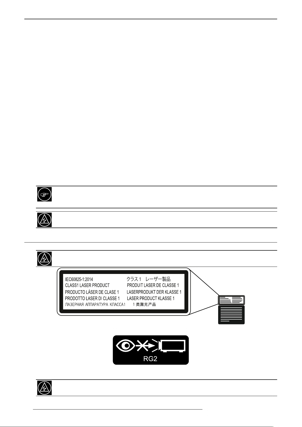
This unit is a CLASS 1 Laser Product that meets the standards IEC60825-1:2014. For more information,
please refer to the Caution label located at the rear of this unit
.
The Laser caution label is located at the rear of this unit.
IEC62471-5 labels located at the top front of this unit.
As with any bright light source, do not stare into the beam when this unit is operating. This unit is rated
RG2 from the IEC 62471-5 classification.
6
R599870 - Force 4K User Manual
Page 7
SAFETY INSTRUCTIONS
Laser Emission port
1.4 EuropeanSpecicInformation
CE mark and Directive 2011/65/EU - ROHS 2 (Europe only)
In accordance with Article 7 and the adoption into national law by 2nd January 2013, this product has been
designed and manufactured in accordance with Article 4. The technical documentation and the written declaration
of conformity that assesses the product conformity can be provided to the competent National Authority upon an
email request to: [email protected]
Other countries: if you wish to dispose of this product, please do so in accordance with applicable national
legislation or other rules in your country for the treatment of old electrical and electronic equipment.
1.5 USAandCanadaSpecicInformation
FCC Information
Changes or modification not approved by Cineversum could void the user’s authority to operate the equipment.
Note: This equipment has been tested and found to comply with the limits for Class B digital devices, pursuant to
Part 15 of the FCC Rules. These limits are designed to provide reasonable protection against harmful interference
in a residential installation. This equipment generates, uses, and can radiate radio frequency energy and, if not
installed and used in accordance with the instructions, may cause harmful interference to radio communications.
However, there is no guarantee that interference will not occur in a particular installation.
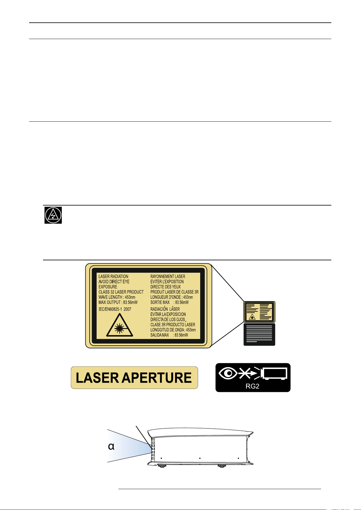
Laser Classification
This unit is a CLASS 3R Laser Product that meets the standards IEC/EN60825-1:2007. For more
information, please refer to the Caution label located at the rear of this unit
Laser radiations: avoid direct eye exposure CLASS 3R Laser Product. Do not look into the lens while in
use. Light source specifications:
-30W Laser diodes x6
-Wavelength 450-460 nm
-Maximum output is 64.12 W
The Laser caution label is located at the rear of this unit.
.
:
Beam divergence angle from lens of this unit
R599870 - Force 4K User Manual 7
LASER APERTURE and IEC62471-5 labels located at the top front of this unit.
α Wide = 71°, α Tele = 39°
Page 8
INSTALLATION GUIDELINES
2.0 INSTALLATION GUIDELINES
2.1 Carrying and installing this unit
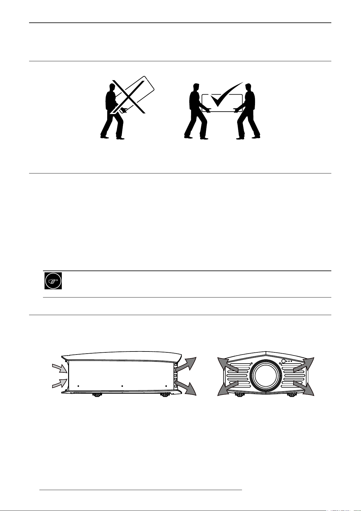
This unit is very heavy : at least two persons are necessary for carrying and installing.
Make sure have at least 2 persons to carry and install this unit
2.2 Precautionduringinstallation
Do not install in this following conditions
This unit is a precision device. Please refrain from installing or using it at the following locations. Otherwise, it may
cause fire or malfunction.
• Dusty, wet and humid places
• Places subject to oily smoke or cigarette smoke
• On top of a carpet or bedding, or other soft surfaces
• Places exposed to direct sunlight
• Places with a high or low temperature
• Do not install this unit in a room that is oily or subject to cigarette smoke. Even a small quantity of smoke or
oiliness can have a long-term impact on this unit.
This unit produces a great amount of heat, and is designed to take in cool air to cool its optical components.
Using the unit at the above locations may cause dirt to attach to the light path, thereby resulting in dark
images or dull colors. Dirt that sticks to the optical components cannot be removed
.
2.3 Maintainclearancefromthewall
Air flow
As the unit discharges a large amount of heat, install it with adequate clearance from the surroundings as shown
below.
B
A
B
Air ow: A air inlets, B air outlets.
B
8
R599870 - Force 4K User Manual
Page 9
INSTALLATION GUIDELINES
Space requirements
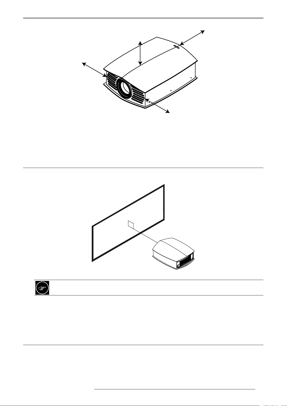
20 cm
15 cm
30 cm
30 cm
Space requirements: 15 cm above this unit, 20 cm at the rear and 30 cm on the left and right sides.
At the front of this unit
Leave the front area of the unit unblocked. If there is any obstructing object in front of the exhaust vent, hot air
will flow back to the unit and cause it to heat up. Hot air flowing out of the unit may cast shadows on the screen
(heat haze phenomenon).
2.4 Installingtheprojectionscreen
Install the projection screen and this unit such that they are perpendicular to each other as showed in the picture
below.
Place this unit perpendicular to the screen.
Use the electronic shift and zoom to correct the picture size and position as needed. You can also use the
feet to adjust the projected picture level.
Screen material suitable for 4K projection.
To optimize the sharpness and detailing of the picture, please choose a screen material optimized for ultra High
resolution (UHD 4K). Avoid any material with uniform patterns as checks that may cause interference artefacts to
occur. If this is the case, you can try to slightly change the size of the projected image to make the interference
patterns less noticeable.
2.5 When to use the High Altitude mode
When using this unit at a location that is higher than 900m above sea level and making the air pressure low
enough to decrease its efficacity cooling this unit, set the “High Altitude Mode” to “On”.
R599870 - Force 4K User Manual 9
Page 10
INSTALLATION GUIDELINES
d
2.6 Ceiling Mounting the Unit
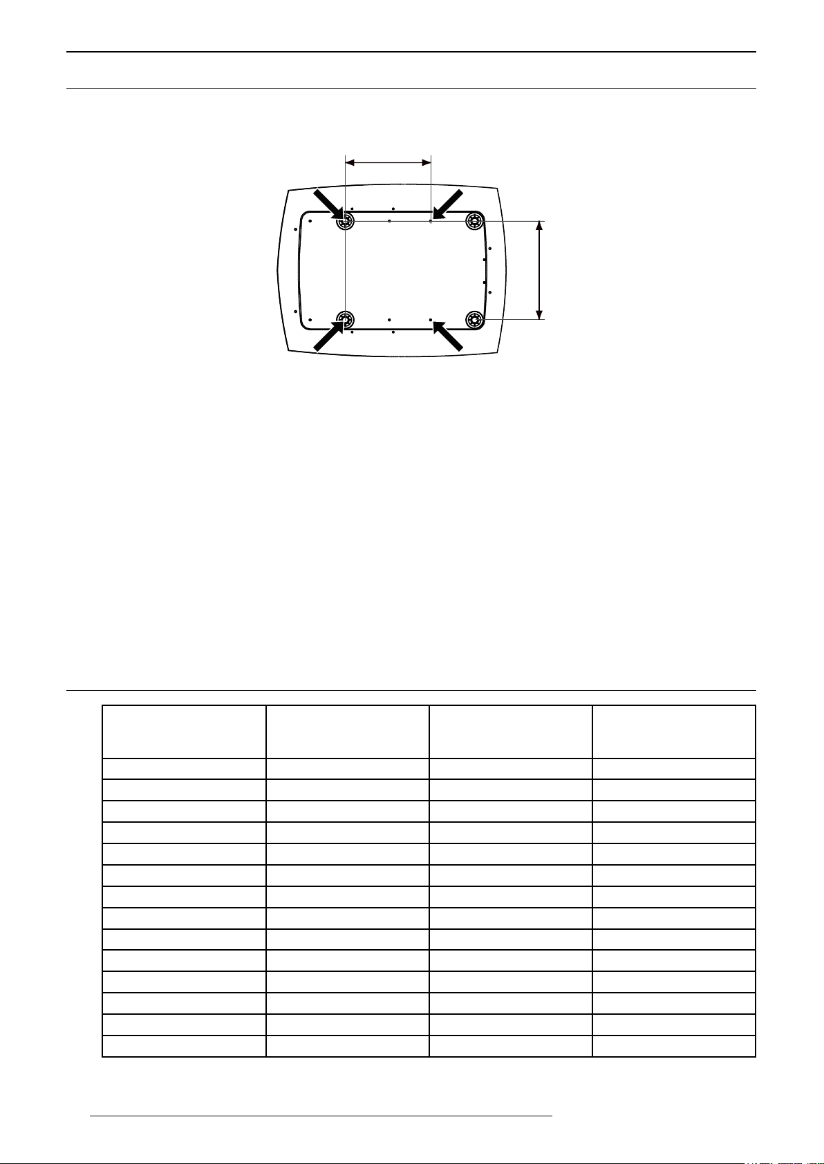
When mounting of this unit is required, make use of the 4 screw holes (M5x20 screws) at the bottom of this unit
indicated by the letter A and B. Note that the B holes are initially populated by the bottom feet, remove the feet
before installing.
B
B
Remove the rear feet to free the B holes when ceiling mounting this unit.
A
D
A
Precautions for Ceiling-mount
• To ceiling-mount this unit, special expertise and techniques are necessary. Be sure to ask your dealer or
specialist to perform mounting. If installation is performed by an unqualified person, it may cause personal
injury or electrical shock.
• Do not mount at places that may be subjected to vibration and shock.
• Depth of the screw holes (A) is 23 mm. Use at least 13 mm long screws but not longer than 23 mm as you
may damage inside the projector.
• Regardless whether the unit is still under guarantee, Cineversum is not liable for any product damage caused
by mounting the unit with third party ceiling mount or when the environment is not suitable for ceiling-mount.
Dimensions
• Distances between left and right holes is D = 337 mm / 13.26 inches.
• Distances between front and back holes is d = 290 mm / 11.42 inches.
2.7 ProjectionDistance
Projection Screen
Diagonal Size
(Aspect Ratio 16:9)
60” (152 cm) 52.3” (133 cm) 29.4” (747 cm) 1m75 - 3m60
70” (178 cm) 61.0” (155 cm) 34.3” (872 cm) 2m06 - 4m21
83” (211 cm) 72.3” (184 cm) 40.7” (103 cm) 2m45 - 5m01
100” (254 cm) 87.2” (221 cm) 49.0” (125 cm) 2m97 - 6m06
110” (279 cm) 95.9” (244 cm) 53.9” (137 cm) 3m27 - 6m67
138” (350 cm) 120.3” (306 cm) 67.7” (172 cm) 4m10 - 8m33
150” (350 cm) 130.7” (332 cm) 73.5” (187 cm) 4m50 - 9m13
180” (457 cm) 156.9” (306 cm) 88.2” (224 cm) 5m44 - 11m04
200” (508 cm) 174.3” (443 cm) 98.1” (249 cm) 6m02 - 12m21
220” (559 cm) 191.7” (487 cm) 107.9” (274 cm) 6m63 - 13m44
240” (610 cm) 209.2” (531 cm) 117.7” (299 cm) 7m24 - 14m67
260” (660 cm) 226.6” (575 cm) 127.4” (324 cm) 7m86 - 15m90
280” (711 cm) 244.0” (620 cm) 137.4” (349 cm) 8m47 - 17m13
300” (762 cm) 261.5” (664 cm) 147.1” (373 cm) 9m07 - 17m50
• The projection screen sizes and projecting distances in the table above are provided only as a guide. Please
use them as reference during installation.
Projection Screen
Base Size
(Aspect Ratio 16:9)
Projection Screen
Height
(Aspect Ratio 16:9)
Projection Distance
10
R599870 - Force 4K User Manual
Page 11
INSTALLATION GUIDELINES
Horizontal Shift
• The distances are calculated for a projection image of 16:9 aspect ratio
2.8 Setting the Lens offset
Adjust the picture position
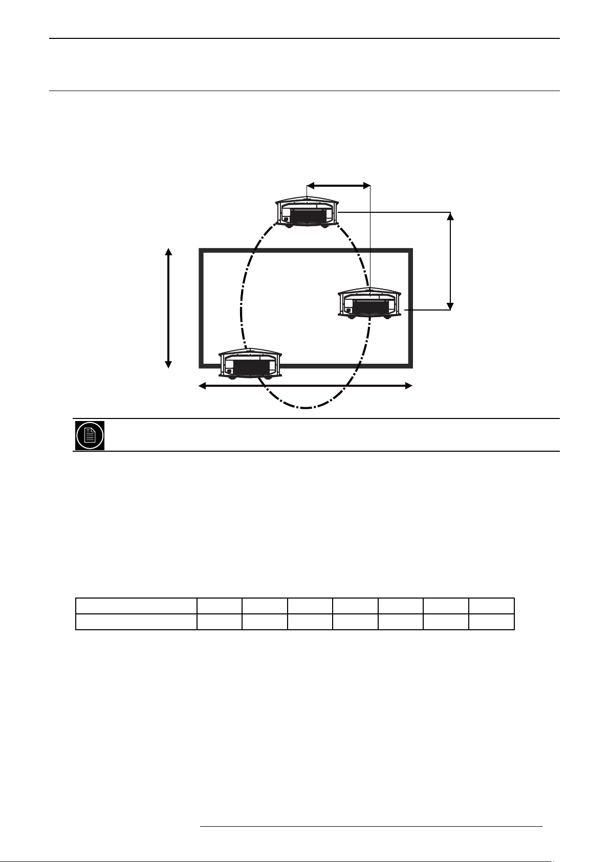
The optimum image can be obtained when the centre of this projector’s lens and the screen are placed
perpendicular to each other. Take note of the projection angle when placing them. You can also use up to +/- 15°
up and down position and configure trapezoidal correction.
+/- 43%
Vertical Shift
+/- 100%
Screen Height
(H)
Screen Base
(B)
This unit comes with a vertical and horizontal shift to suit most installations. Make sure that your installation
does not exceed 100% vertical offset and 43% horizontal offset to avoid trapezoidal correction.
This unit comes with a optical shift that features vertical and horizontal adjustment of the projection screen
position. Adjust the picture to your screen.
• The Vertical Shift level is between -100% and 100% of the Screen Height (H).
• The Horizontal Shift level is between -43% and 43% of the Screen Base (0.43 x B).
• If the projector is not installed perpendicularly to the screen, use keystone correction to fulfill your screen. Note
that using keystone correction, may be disabled by 3D projection. If you want the best possible 3D pictures, It
is not recommended to use trapezoidal correction.
• If you plan to use the vertical and horizontal shifts without keystone correction, make sure to not exceed the
values contained in the tab below:
Left / Right shift 0% 10% 20% 25% 30% 35% 43%
max. up / down shift 100% 87% 72% 58% 45% 22% 0%
•Adjust the picture position
The projector has motorized vertical and horizontal shifts. Browse into the Menu to the [Lens Control] setting into
the Installation menu, select the shift adjustment. Or use the direct access button on the Remote Control Unit
[Lens Control] to make the lens adjustment. You can use self-generated test pattern of the projector or an external
pattern, from a calibration DVD by example, by setting the Adjust pattern option to Off.
•Adjust the picture Zoom
Into the [Lens Control] menu, press the [Ok] button to access the Zoom adjustment. Use the up and down buttons
to adjust the picture size until the screen is completely filled.
•Adjust the Picture Focus
From the [Lens Control] menu, press the [Ok] button to access the Focus adjustment. Use the up and down
buttons to adjust the picture focus
R599870 - Force 4K User Manual 11
Page 12

INSTALLATION GUIDELINES
Using Installation Modes
You can save the current picture position, zoom and focus into one of the 10 Installation Modes. Each Installation
Mode uses a memory that stores the current position, zoom, focus of the lens. Additionally, you can set a custom
name of 10 characters or less.
•Current lens setup
All the lens settings will be stored by default into the Installation Mode 1. You can also copy a Mode into another
using the Mode Copy function. Menu > Installation > Installation Mode > Mode Copy. Then you can call back
anytime later the current lens setup using the direct access button [Mode 1] up to [Mode 3] on the RCU.
•Limitations of use
Each memory can store a different picture size and position, but there are limitations on the possible pictures
sizes and positions because of the projector being at a fixed location. In order to calculate the best position of the
projector toward the screen, the installer has to make sure that among the different desired pictures, the smaller
one with the smaller zoom, is within the offset limits (horizontal and vertical shifts) of the projector. Once the
position of the projector is determined by the smallest possible picture, double check that the larger one does not
exceed the zoom capacity.
12
R599870 - Force 4K User Manual
Page 13
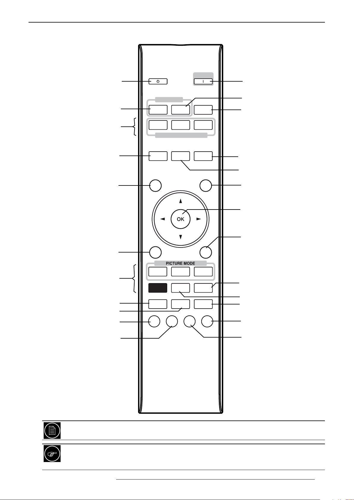
REMOTE CONTROL UNIT (RCU)
3.0 REMOTE CONTROL UNIT (RCU)
Stand by
Selects an [HDMI1] input
Memory settings [Mode1 to 3]
[Lens Control]
Focus, Zoom, Shift
[Hide] the current display
STAND BY
INPUT
HDMI 1 HDMI 2
MODE 1
LENS
CONTROL
HIDE
MODE 2 MODE 3
SETTING MEMORY
LENS AP.
ON
INFO.
ANAMO.
LIGHT
Power [On]
Selects an [HDMI2] input
Displays [Info] menu
[Anamo.]rphic settings
Sets the [Lens Ap.]erture
Backlight button
Confirm button
[Back] to previous menu
Display [Menu]
Selects a Picture Mode
M.P.C. Settings)
CMD Clear Motion Drive
Gamma Adjust
Color Temp. Adjust
MENU
NATURAL
PICTURE
MODE
M P C
GAMMA
CINEMA
COLOR
PROFILE
C.M.D
COLOR
TEMP.
3D
FORMAT
BACK
HDR
GAMMA
SETTINGS
ADVANCED
MENU
PIC.
ADJ.
Gamma setting
Color Profile Menu
Displays [Advanced Menu]
Basic Picture Adjust
Selects [3D Format]
The remote control unit can be used by having the signal reflected off a screen, as the effect of signals
reflected differs with the type of screen used, operable distance may decrease.
If the remote control has to be brought closer to the projector to operate, it means that the batteries are
wearing out. When this happens, replace the batteries. Always insert the batteries according to the +
and - marks.
R599870 - Force 4K User Manual 13
Page 14
GETTING STARTED
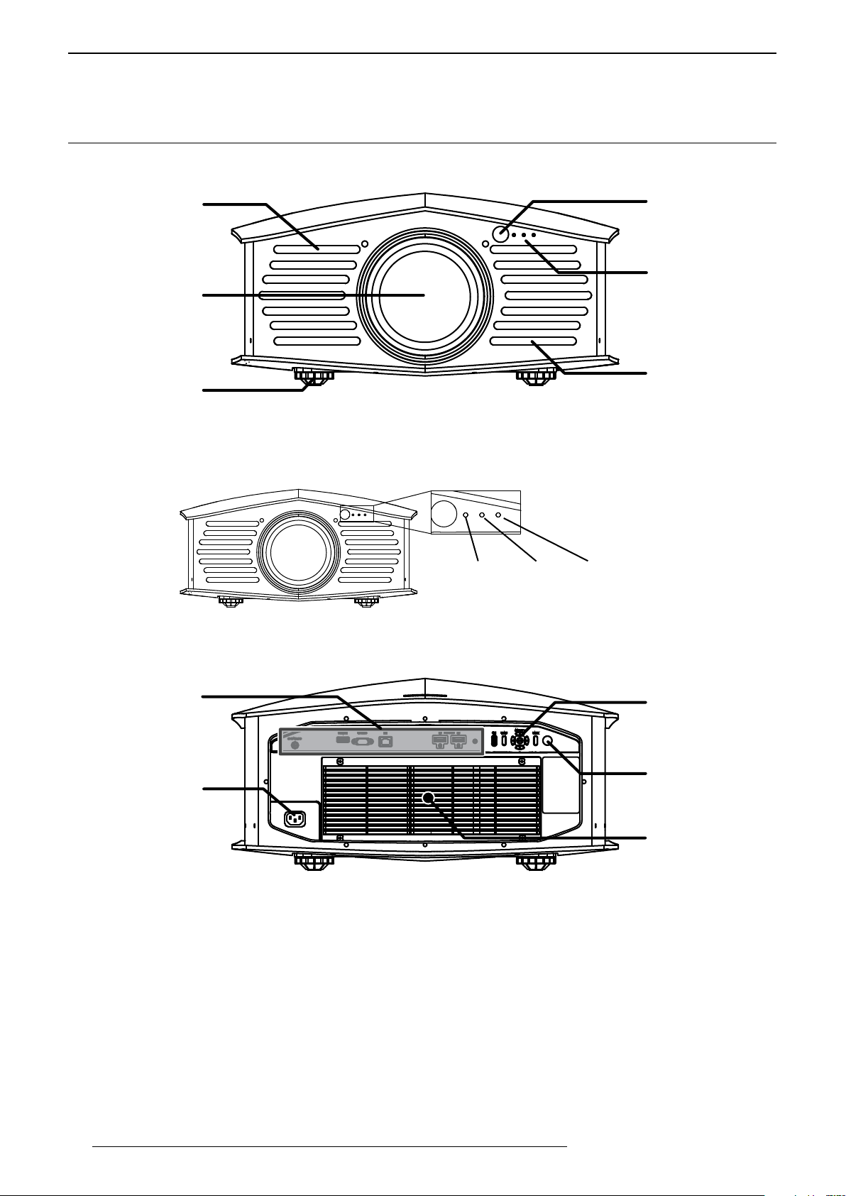
Front IR receiver
4.0 GETTING STARTED
4.1 GeneralView
Front side
Air Outlets
Operating LEDs
Optical Lens
Air Outlets
Adjusting Feet(*)
(*) The height of this unit may be adjusted by turning the adjusting feet from 0 up to 5mm. This may be used to
finely adjust the picture (horizontal) level.
Operating LEDs position
From left to right: Standby/On, Light, Warning.
Rear side
Input Panel
Main Power
terminal
Standby/On - Light - Warning
Back Panel
Rear IR receiver
Air Inlet and filters
• Input Panel: connect your video source to the correct input.
• Main Power terminal: connect the main power cord as shown below.
• Back panel and operation buttons.
14
R599870 - Force 4K User Manual
Page 15
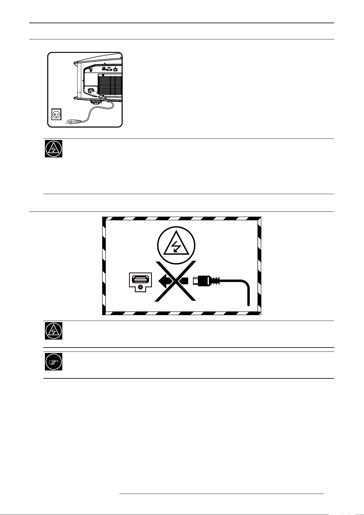
4.2 ConnectingthePowerCord
• Before plugging in the Power Cord, ensure that all devices have been
connected to their respective inputs of this unit.
• Connect the power cord to the power input terminal of the projector.
To prevent Fire and Electric shocks:
1) The power consumption of this unit is large. Please connect it directly to the wall outlet.
2) When you are not using the projector, please unplug the power cord from the outlet.
3) Connect it using only the power cord supplied.
4) Do not use a voltage other than the indicated power voltage.
5) Do not place a heavy object on the power cord, or heat or pull it.
6) Do not unplug the power cord with wet hands.
GETTING STARTED
4.3 CautionwhenconnectingaDevicetoHDMIInput
Prior to connecting any device to this unit, switch the projector in standby mode. Never connect a HDMI
source to this unit when the projector is in operate mode. The HDMI termination is a self-powered
connection and can cause electric discharges.
The HDMI 2.0 inputs are compatible with HDCP 2.2 and supports video signals up to 18 Gbps. It is
strongly recommended to use exclusively cables rated for 18 Gbps bandwidth to watch 4K contents,
otherwise this unit will suffer from handshake issues and video freezes.
R599870 - Force 4K User Manual 15
Page 16
GETTING STARTED
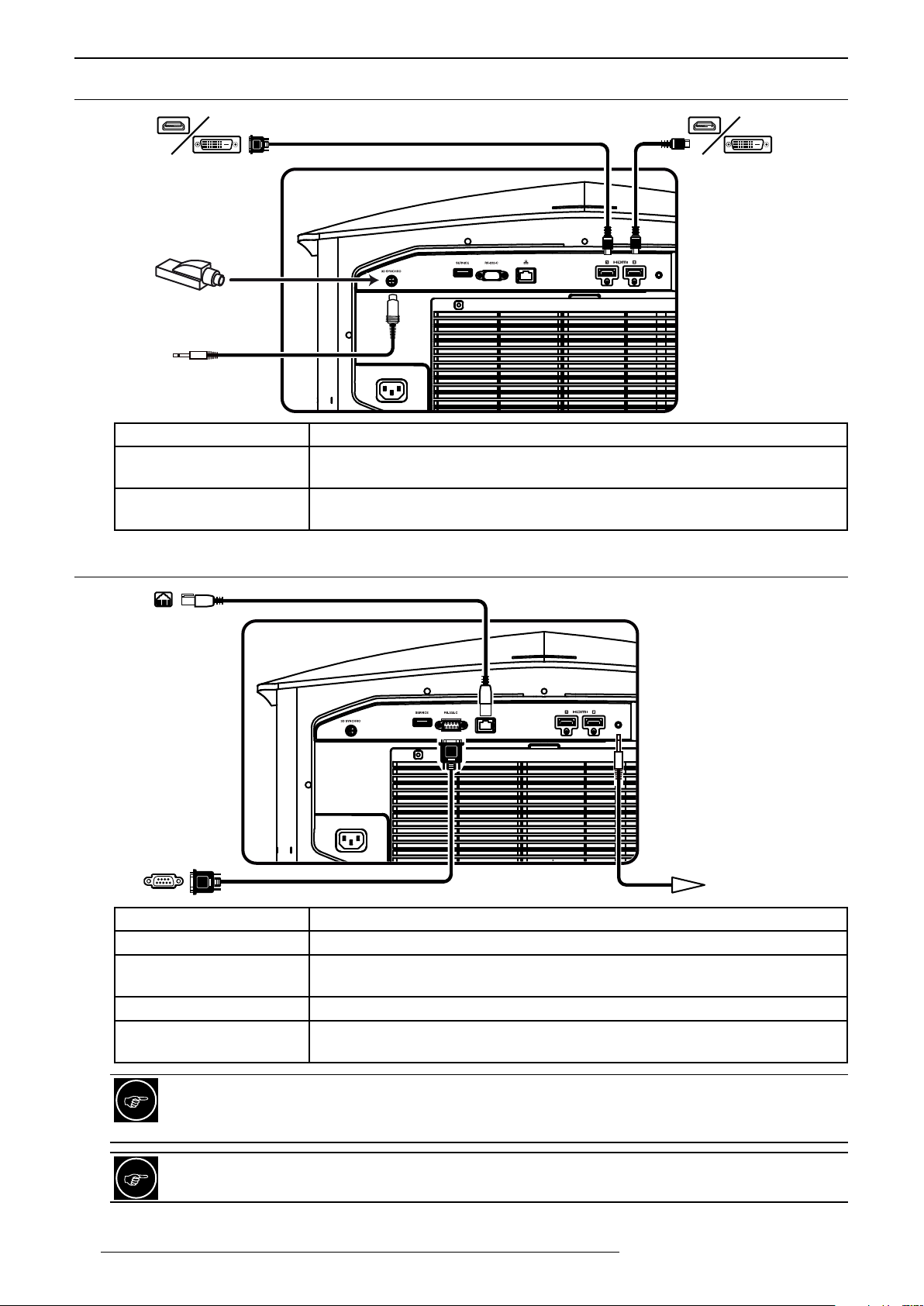
4.4 ConnectingaVideoSourcetotheProjector
HDMI 1
RF Dongle
or
3D syncro
Emitter
Audio/Video Connection Device to connect
HDMI 1, HDMI 2
(DVI compatible)
RF Dongle or 3D Synchro
Emitter
HDMI or DVI-D sources: Blu-ray Disc player, DVD-player equipped with an HDMI
output, Game Console, Computer with DVI-D output.
Connect the RF Dongle emitter to control the active 3D shutter glasses or any
other 3D Synchro apparel. 3-PIN mini-DIN interface, 12V.
4.5 ConnectinganAutomationorControldevice
HDMI 2
LAN to rooter
for Automation
RS-232C
for Automation
12V Trigger
Connection Device to connect
RS-232 C Automation Device, Control Device or Computer with RS-232 capability.
12V Trigger DC power supply output 12V@100mA to control either a screen or an anamorphic
lens motorization.
LAN Automation Device, Control Device or Computer with RJ-45.
USB This terminal is used only for service and software update. The terminal is
compatible with standard USB flash drive.
16
CONNECTING AN AUTOMATION/CONTROL DEVICE
This unit can control or be controlled by using several input/output terminals. Each terminal is ruled by
specific protocols. Please refer to Appendix for more information.
ECO Mode turn to On prevents this unit to receive and to respond to automation commands when it is in
standby. Turn Off ECO mode if you plan to take full control of this unit with an automation system.
R599870 - Force 4K User Manual
Page 17
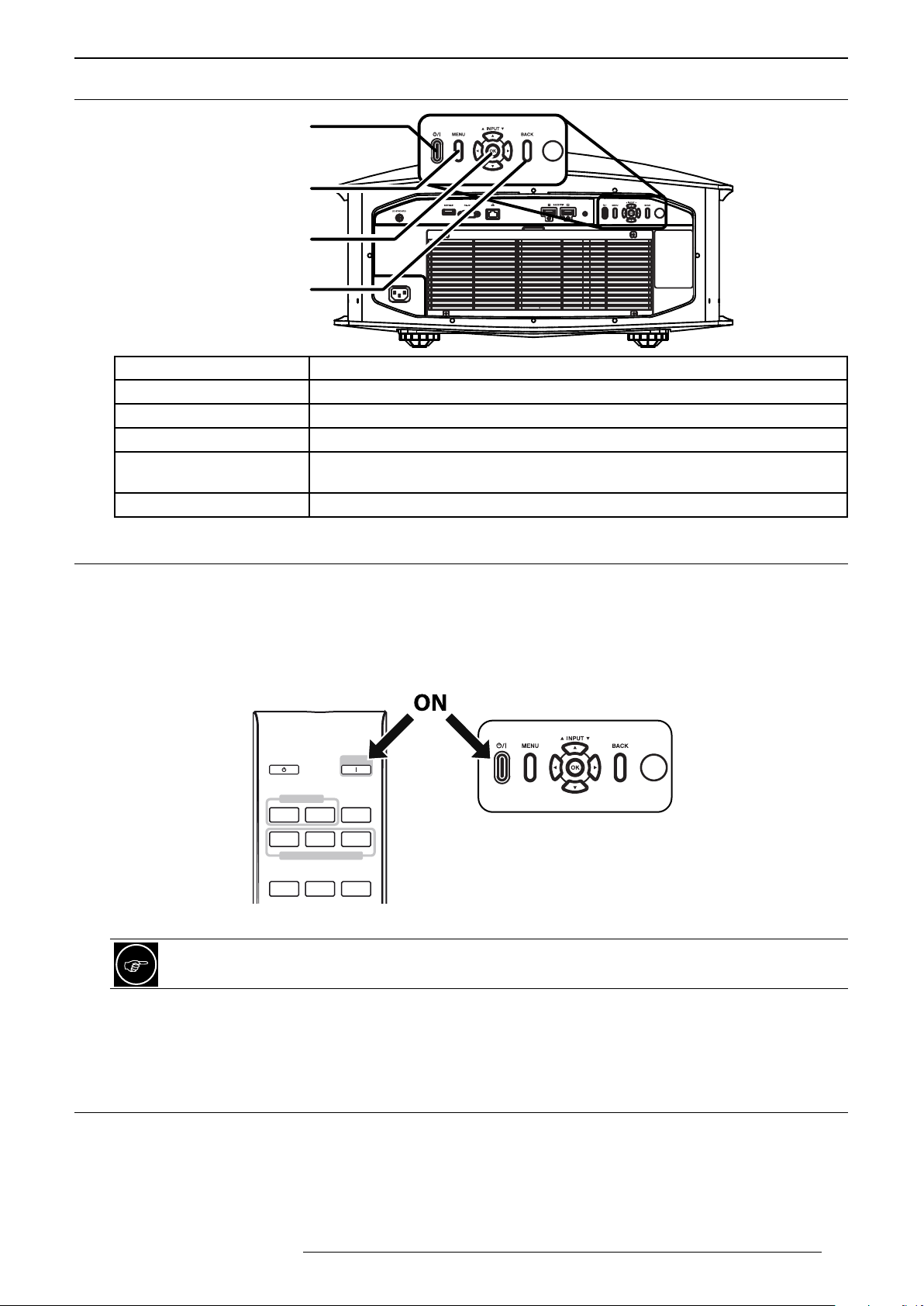
4.6 BackPanelandOperatingButtons
Power button
Menu
OK button
and
Directional Keys
Back
Button Description
Power To turn On or Off the projector.
Menu To display the On Screen Display (OSD) Menu.
OK button To select or to confirm action.
Directional keys Up and Down keys may be used to switch Inputs between HDMI1 and HDMI2.
Use the Navigation Keys to navigate into the On Screen Display (OSD) Menu.
Back To return to previous menu or cancel action.
GETTING STARTED
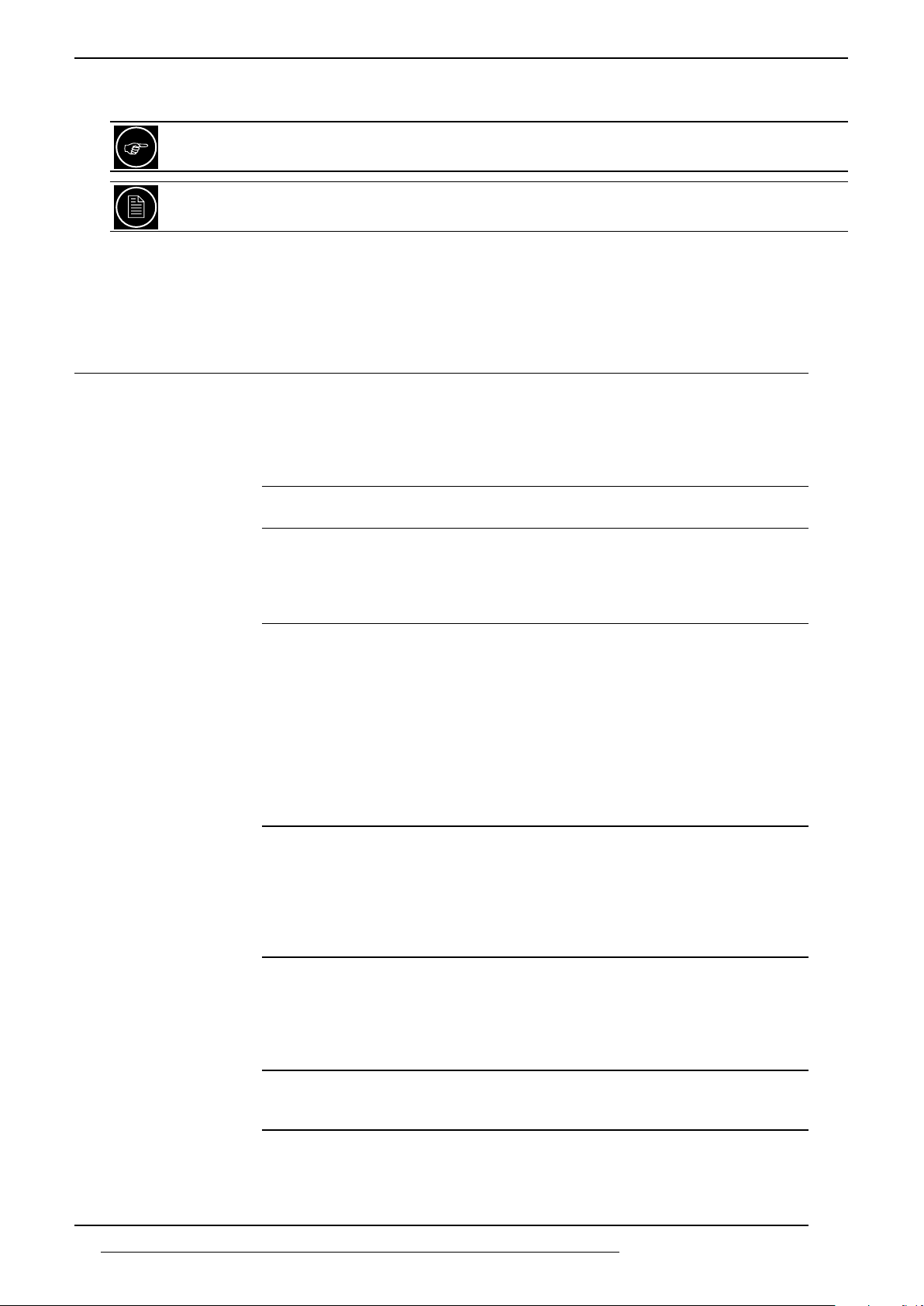
4.7 First start up
Remove the lens cap or lens protection then make sure that the power cord is connected to this unit
Turn the power ON
You can turn ON this unit with the remote control unit (RCU) or directly pressing the power button located on the
back panel. During startup procedure, this unit Standby/Power LED will blink green. Wait until complete power ON
indicated by a steady green light on the Standby/Power LED.
INFO.
MODE 2 MODE 3
LENS AP.
ANAMO.
RCU
ON
Back panel
STAND BY
INPUT
HDMI 1 HDMI 1
MODE 1
SETTING MEMORY
LENS
CONTROL
If “Eco mode” is On, the standby led will not be light up red during Standby mode.
Select the correct Input
Once this unit is powered ON, please select the correct Input by pressing the corresponding button on the
Remote Control Unit or the O/I button on the back panel of this unit.
4.8 TurnthePowerOff
You can turn OFF this unit by using either the RCU or the Power button on the rear control button panel.
Press the Standby button and a message appears on the screen to ask to confirm the command. You can cancel
the command by pressing the “Back” button or turn of the device by pressing the “Standby” button again.
The Standby LED will switch from steady green to blinking red light and the fans will run for about 10 seconds
to finish the shutdown procedure. During this Cool-down sequence, do not disconnect the power cord. The cool-
R599870 - Force 4K User Manual 17
Page 18
MENU STRUCTURE
down procedure is finished when the “Standby/On” LED indicator stops blinking red and switches to a solid red
light.
The power cannot be turned off within approximately 30 seconds after it has been turned on.
The power cannot be turned On again until the Cool-down sequence (10 seconds) is complete.
It is recommended to disconnect the power plug when the unit is not to be used for a prolonged period
of time.
5.0 MENU STRUCTURE
MAIN MENU SUBMENU AVAILABLE OPTIONS
Picture Adjust Picture Modes
(5+6 User)
Expert Picture Modes
(*) require individual calibration
Advanced Picture Mode
(press OK to enter this menu)
Color Profiles
the list varies upon the selected
Picture Mode
(*) require individual adjustment
and/or calibration
Advanced Color Profile Color Management: Off / On
Color Temp Xenon Modes
Advanced Color Temp If Custom 1-2, choose Correction Value
Gamma If Color Profile is Film1 to 2
(Video and drama programs) Natural
(Vivid colors suitable for all movies) Cinema
(HDR movies, auto-detected) HDR
(Movie films) Film
THX
User 1 - 6
THX bright(*)
THX dark(*)
Dynamic Control Off, Mode 1, Mode 2
LD Power Low, Mid, High
Aperture -15 +0
User Name Edit (if f User 1 - 6 selected)
edit name 10 char. max
(HDTV REC-709) BT.709
(Movies REC 2020) BT.2020
(Cinema DCI-P3) DCI
(Animations) Anime
(Movies with enhanced colors) Cinema
(HDR contents) HDR
(Eastman Kodak movies) Film1
(Fujifilm movies) Film2
THX
Off
Custom 1 - 6(*)
Color selection
Axis Position -30 +30
Hue -30 +30
Saturation -30 +30
Brightness -30 +30
Reset Confirm
(Film projector) Xenon1
(DCI projector) Xenon2
Preset value:
5500K - 6500K - 7500K - 9300K
High Bright - HDR - Custom 1-2
Gain and Offset settings
Reset Confirm
(standard) Film1
(more contrasted) Film2
Custom1 to 3
If Color Profile is THX THX
18
R599870 - Force 4K User Manual
Page 19

MENU STRUCTURE
Picture Adjust Gamma If Color Profile is not Film nor THX
Normal, 2.2, 2.4, 2.6,
Cinema 1, Cinema 2
HDR (ST.2084), HDR (Hybrid Log)
Custom 1 to 3
Advanced Gamma If Custom 1 - 3, Gamma Corr. Value
1.8 - 2.6 (within 0.1 steps)
Cinema 1, Cinema 2
HDR (ST.2084), HDR (Hybrid Log)
Import
Color Selection White / Red / Green / Blue
Picture Tone -16 +16
Dark Level -7 +7
Bright Level -7 +7
Reset Confirm
MPC Level Graphic Mode (NA for 3D) On (4K), Off
Enhance 0 - 10
Smoothing 0 - 10
Noise Reduction 0 - 10
Reset Confirm
Blur Reduction Low Latency (Game Mode) On, Off
Clear Motion Drive (NA if Low Latency is On)
Off, Low, High, Inv. telecine
Motion Enhance Off, Low, High
Contrast -50 +50
Brightness -50 +50
Color -50 +50
Tint (reddish to greenish) -50 +50
Reset Profile settings Confirm
Input Signal Input level Auto
(16 - 235) Standard
(0 - 255) Enhanced
(16 - 255) Super White
Color Space Auto,
YCbCr(4:4:4)
YCbCr(4:2:2)
RGB
Aspect Zoom
Auto
Native
3D Setting 3D format
Auto / Side-by-Side / Top & Bottom / 2D
Parallax -15 +15
Crosstalk Cancel -8 +8
HDMI2 EDID (HDMI2 only) A, B
Installation Installation Mode Mode Select Mode 1 - Mode 10
Name Edit
Mode Copy
Lens Control Focus
Zoom
Shift
Image Pattern On, Off
Lock On, Off
Lens Center Confirm
R599870 - Force 4K User Manual 19
Page 20

MENU STRUCTURE
Installation Pixel Adjust Adjust On, Off
Adjust Area Whole, Zone
Adjust Color Red, Blue
Adjust Pattern On, Off
Adjust Pattern Color White - Cyan/Yellow
Adjust (Pixel)
Adjust (Fine)
Reset Confirm
Mask On, Off
Top, Bottom, Left, Right 0 - 220
Anamorphic Off, A, B
Screen Adjust
(Color Profile must be On)
Installation Style Front, Ceiling Mount, Rear, Ceiling Mount (Rear)
Keystone (vertical)
(N.A. if Pincushion is On)
Pincushion 0 - 16
High Altitude Mode (900m or higher) On / Off
Display Setup Back Color (when no signal) Blue, Black
Menu Position select position
Signal Display (active input) On, Off
Logo On, Off
Language select between 13 languages
Function Trigger Off
Off Timer (in hours) 1H, 2H, 3H, 4H, Off
ECO Mode On, Off
Network DHCP Client On, Off
Remote Code Press [Menu] + [Back] A, B
Hide Mode
Factory Reset
Software Update
Information Input
Source
Resolution
H, V Freq
Color Depth
Colorimetry
HDR
Light Source time
Soft Version
PS Version
Screen No. 000 - 255
On, Off
-16 +16
Power
Anamo
Inst. Mode 1 - Inst. Mode 10
IP Address 192.168.0.2
Subnet Mask 255.255.255.0
Default Gateway 192.168.0.254
Mac Address Display MAC
Set Confirm
20
R599870 - Force 4K User Manual
Page 21
PICTURE ADjUST
6.0 PICTURE ADJUST
6.1 PictureModesandColorProles
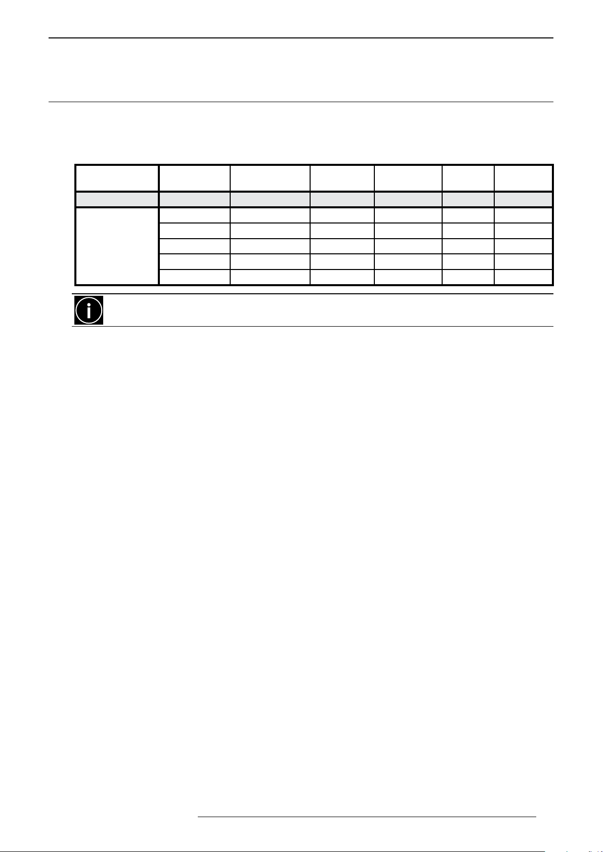
The preset Picture Modes are available through this menu and can be applied to any input. A picture mode retains
the picture adjustments. When adjusting the Picture Mode, you can also select pre-configured Color Profiles.
Available picture modes
Type of source Dramas
or Videos
Picture mode Natural Cinema Film HDR THX Custom
BT.709 BT.709 Film1 BT.2020 THX
BT.2020 BT.2020 Film2 BT.709
Color Profiles
Accurate color temperature may require professional tools such as dedicated software and colorimeter.
Wait at least 15 minutes after startup before modifying the picture settings.
DCI Cinema DCI
Anime DCI
HDR HDR
Digital Cinema
or HDTV
Movies
in general
HDR
sources
THX
sources
User 1 to
Picture Mode description
•Natural
Image quality that focuses on natural color and gradation reproduction. For drama footage and TV series.
•Cinema
Reproduces the image in vivid colors. Suitable for all movies shot for cinemas.
•HDR
This mode makes full use of the wide color gamut and contrast encoded into UHD Blu-ray discs and 4K
contents HDR.
User 6
•Film
Reproduces faithfully the texture of movie films.
•THX
Best image quality settings recommended and certified by THX. Expert calibration and a computer with
RS-232 port is required to enable the two dedicated THX profiles.
•User 1 to User 6
Enables user-defined image quality data to be saved and retrieved on demand. Every color profiles can
be selected.
Color Profiles
There is a total of 9 preset Picture Modes and 6 user picture modes. For each picture mode, you may choose one
of the 9 Color Profile presets of one of the 6 custom color profiles:
• BT.709 color space that is calibrated to best match BT.709
• BT.2020 color space that is calibrated to best match BT.2020
• DCI available with Cinema Picture Profile and adjusted to DCI-P3 color space.
• Anime best suited for CG animation works with bright colors.
• Cinema available with Cinema Picture Profile and adjusted to movie sources with bright, saturated colors.
• HDR color space specifically adjusted for video sources using HDR contents with non-conventional gamma.
• Film1 available with Film Picture Profile, uses the Xenon filter and adjusted to Eastman Kodak film tone
• Film2 available with Film Picture Profile, uses the Xenon filter and adjusted to Fujifilm film tone.
• THX color profile is reserved for the THX picture modes and THX standard.
R599870 - Force 4K User Manual 21
Page 22
PICTURE ADjUST
User Name Edit
MENU
BACK
>
>
Name
User 1
Clear
All Clear OK
Exit
Select
Operate
SPACE
6.2 AdvancedPictureMode
Dynamic CTRL
Expands dynamically the brightness range of a video source directly through the laser light source. Turn it Off, set
to Mode 1 for a low correction or to Mode 2 for stronger effect.
LD Power
Set the laser LED power used by the current Picture Profile. For standard viewing conditions, the LED power is
set to Mid. Depending on the screen size and the ambient light, you may set it to Low to obtain a dimmer image,
or to set it to High for a much brighter image.
Aperture
The lens is equipped with a variable electronic aperture. You can set the iris opening to a fixed position, adjust to
the best aperture from partially closed (-15) to fully opened (0).
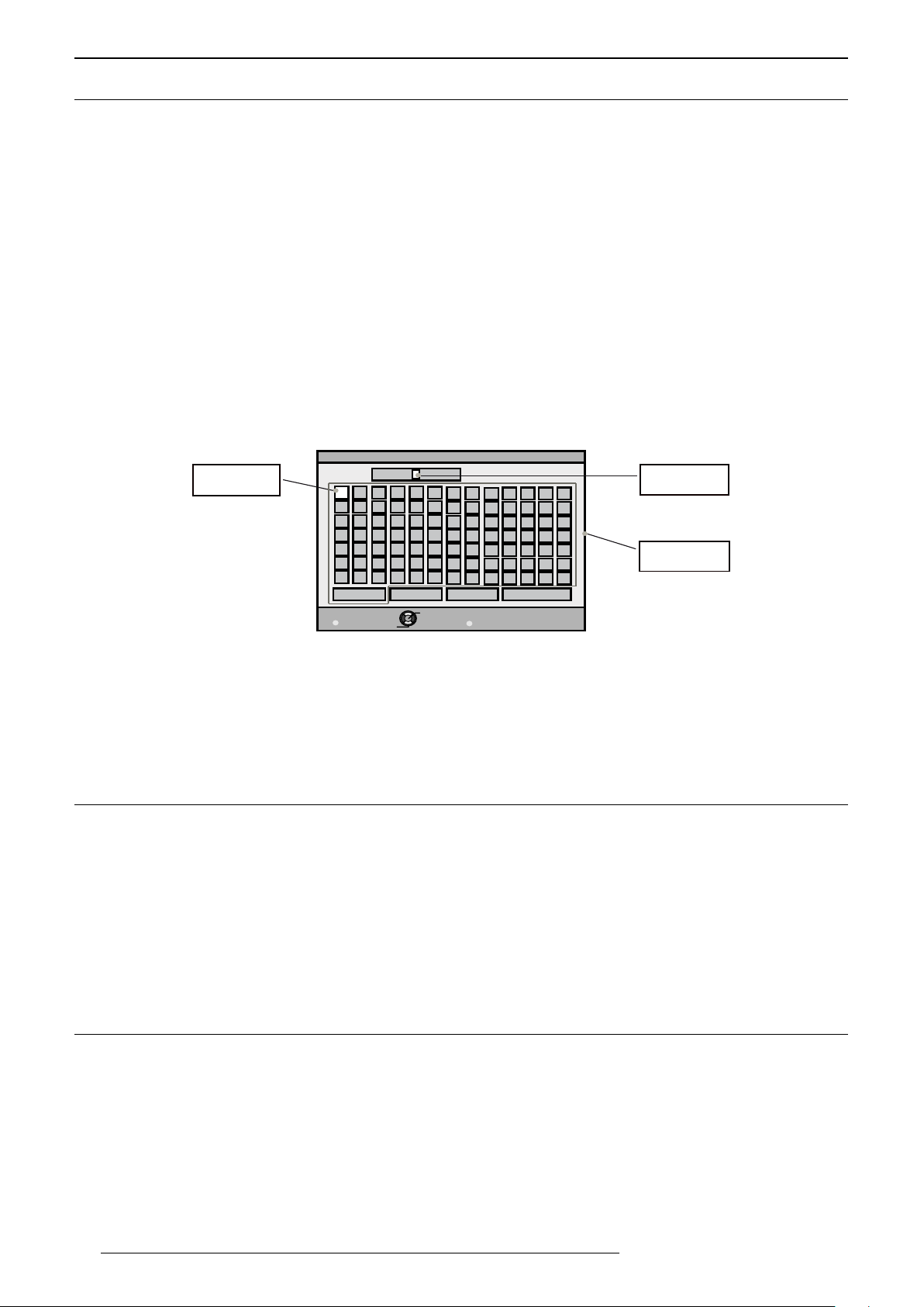
User Name Edit
You can edit the picture mode names User 1 to 6 using a maximum length of 10 characters. You can use alphabet
letters, numbers and symbols:
Select cursor
Input cursor
Character list
a) Select the user name you want to edit from User 1 to User 6. Press [OK] to enter the edit mode.
b) The input cursor displays the place where the new character will be insert. It moves automatically as a
character is selected. Use [UP], [DOWN], [LEFT] or [RIGHT] to select a character and press [OK] to insert.
c) Press [BACK] to exit edit mode.
Clear: To delete a character: Move the cursor to the desired location and press [OK] to delete the specific character.
All Clear: To delete all characters. OK: To save the current name, a save confirmation will appear.
6.3 AdvancedColorProle
Expert Calibration is accessed only by using a programmable IR-RCU, RS-232C or LAN control. Two additional
Picture Modes can be activated, designated as THX bright and THX dark that have to be calibrated. Once done,
these profiles are stored and displayed in the picture mode menu list but will not be modifiable.
Color Management (TSL adjustments)
The Color Management gives the installer an unique calibration ease with the integrated Color Adjustment menu:
each primary, secondary colors can be independently calibrated to obtain a precise color balance in a snap.
Adjust the Red, Green, Blue, Yellow, Cyan, Magenta tints, their saturations and luminances and store them into
Custom profiles. Available adjustments: Axis Position, Hue, Saturation and Brightness.
6.4 Color Temperature Presets
Color temperature stands for the spectral properties of a light source. Low color temperature implies warmer
ambiance (more yellow/red) while high color temperature implies a colder light (more blue). Depending on the
Picture Profile selected, this setting can be set to:
• Xenon 1 uses the Xenon filter and color compensation to reproduce a film projector
• Xenon 2 uses the Xenon filter and color compensation to reproduce a digital cinema projector
• Preset: from 5500K / warm colors, 6500K, 7500K and 9300K / colder colors.
• High Bright used for maximum brightness output available.
• HDR saturated colors that matches HDR standards.
• Custom 1 and Custom 2 that can be used to adjust color temperature to specific environment.
22
R599870 - Force 4K User Manual
Page 23
PICTURE ADjUST
A Custom setting allows a fine adjustment of a Color Temperature by selecting it in the Correction Value menu.
Adjust the Gain values (bright part) and Offset values (dark part) for each color Red, Green and Blue.
Accurate color temperature may require professional tools such as dedicated software and colorimeter.
Wait at least 15 minutes after startup before modifying the picture settings.
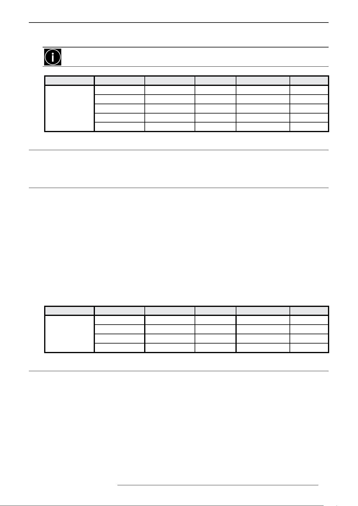
Picture mode Natural Cinema Film HDR THX
5500K - 9300K Xenon 1 Xenon 1 5500K - 9300K 6500K
High Bright Xenon 2 Xenon 2 High Bright
Color Temp.
HDR 5500K - 9300K HDR
High Bright
HDR
6.5 AdvancedColorTemperature
When selecting a Custom color temperature, you can manually set the Gains and Offsets of each primary color:
red, green and blue to finely adjust the color balance.
6.6 Gamma
Gamma is the relationship between the color values of the data and the color values displayed. The Gamma
coefficient makes it possible to adjust the brightness of the mid tones only without affecting the very bright and
very dark areas. If gamma is set too high, middle tones appear too dark. If it’s set too low, middle tones appear
too light. Depending on the current active Picture mode, the Gamma setting can be set to:
• Numeric value of 2.2, 2.4 or 2.6
• Film1: standard gamma
• Film2: slightly more contrasted gamma
• Cinema 1: emphasis on gradations
• Cinema 2: emphasis on contrast
• HDR(ST2084): suited for HDR contents that uses with a Perceptual EOTF Gamma (HDR10)
• HDR(Hybrid Log): Suited for viewing broadcast HDR contents such as ones by BBC or NHK
• Normal: Standard setting for normal viewing.
• THX: video gamma of THX standard
• Custom 1 to Custom 3: fine tune the gamma setting according to the user’s preference.
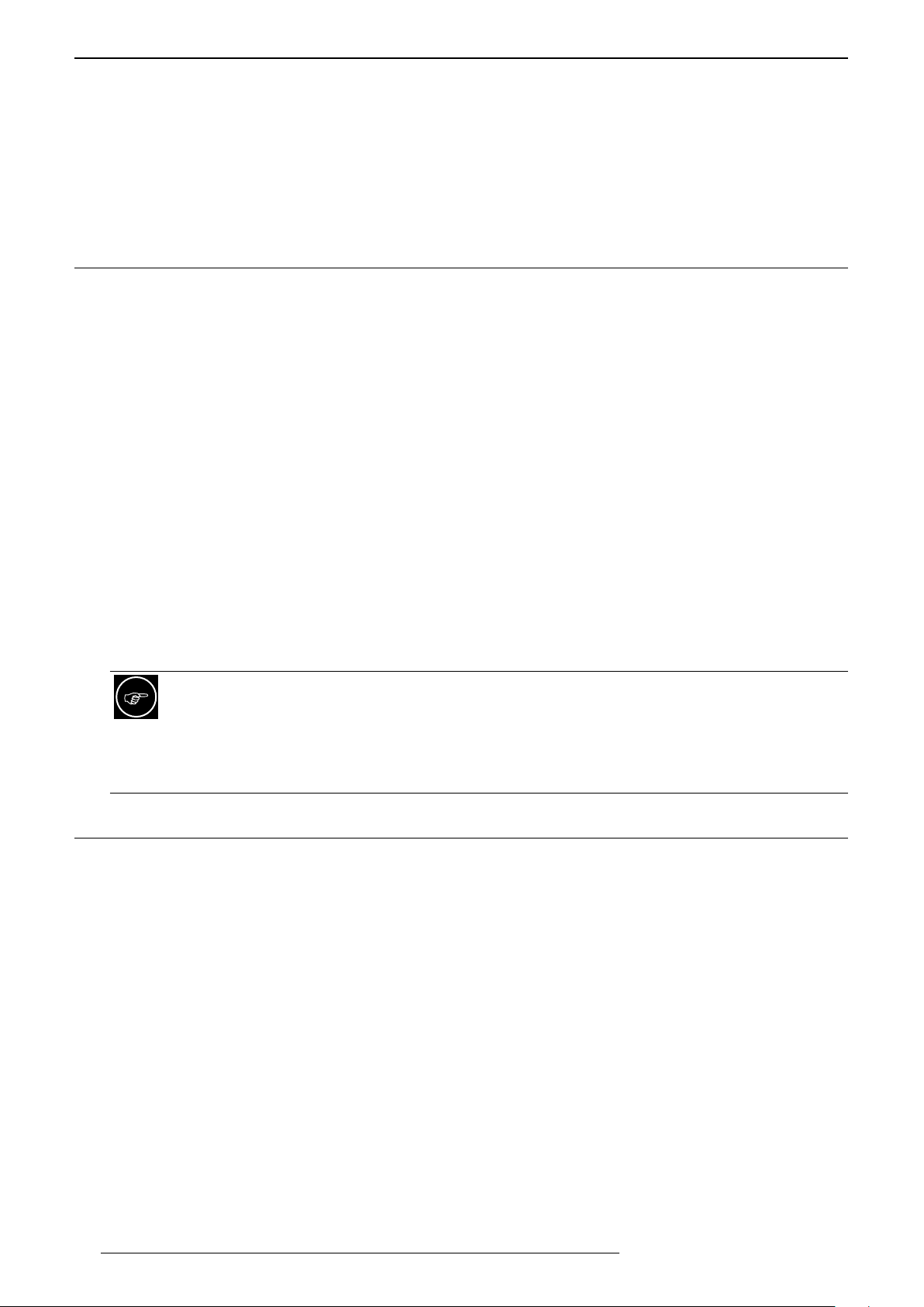
Picture mode Natural Cinema Film HDR THX
2.2, 2.4, 2.6 2.2, 2.4, 2.6 Film 1 2.2, 2.4, 2.6 THX
Gamma.
Cinema 1 or 2 Cinema 1 or 2 Film 2 Cinema 1 or 2
HDR(ST.2086) HDR(ST.2086) HDR(ST.2086)
HDR(Hybrid Log) HDR(Hybrid Log) HDR(Hybrid Log)
6.7 AdvancedGamma
Correction Value
The Custom data can be set to a correction value: a numeric value that will act as a gamma coefficient between
Film 1, Film 2, Cinema 1, Cinema 2, HDR(ST.2084), HDR(Hybrid Log), 1.8-2.6 or Import.
Color Selection
Select the color to which the Picture Tone, Dark / Bright Level settings would apply. Choose between White, Red,
Green and Blue.
Picture Tone
It allows a fine adjustment steps of the global picture brightness while maintaining the correct contrast level to
keep good black and bright levels. Sets the overall exposure from -16 (under-exposed, darker) up to +16 (overexposed, brighter)
R599870 - Force 4K User Manual 23
Page 24
PICTURE ADjUST
Dark / Bright Level
This setting modifies the gamma curve locally in the dark and bright areas.
• Dark Level adjust gamma curve between 0 IRE and 15 IRE, each color can be adjusted from -7 to +7.
• Bright Level adjust gamma curve between 85 IRE and 100 IRE, each color can be adjusted from -7 to +7.
Reset Gamma
Prompt a confirmation to reset the current Gamma settings to default.
6.8 MultiplePixelControlLevel(MPCLevel)
The MPC Level control enables the use and fine tune all the aspects of the rendition of native 4K contents, UHD
disc videos or 4K Interpolated processing.
Graphic Mode
Select whether the content needs a high precision (strong sharpness) or if it is a graphic. Preferably sets this
setting to On when viewing UHD material or mastered in 4K contents.
Enhance
Enhance: enhances the sharpness of foreground objects detected in the picture. Setting range: 0 - 10.
Smoothing
Smoothing: enhances the blurriness of backgrounds for increased the global sense of depth. Setting range: 0 - 10.
Noise Reduction
Noise Reduction: reduces the digital noise of the video picture. Setting to 0 for a weak noise reduction, up to 10
for a stronger one.
Analysis screen
Pressing the [Before/After] button enables you to toggle between the state before adjustment and after adjustment.
Analysis screen:
You can enlight the different areas processed by the 4K Interpolation by pressing [P.Analyser] button or
twice the [MPC Level] button on the RCU when browsing the MPC Level sub menu.
-Areas affected by the Enhance parameter are colored Blue and Green.
-Areas affected by the Dynamic Contrast parameter are colored Red and Yellow.
-Areas affected by the Smoothing parameter are colored Black.
6.9 BlurReduction
Low Latency
To set drop the latency drastically to the cost of picture enhancement process. Set to On when playing video
games or when installed for real-time simulators.If set to On, Clear Motion Drive is disable.
Clear Motion Drive (400Hz, works with 3D)
The Clear Motion function uses up to 400Hz video processing to render a smooth motion for movies shot at 24Hz
or HD movies at 60Hz. Set the correct level between:
• Off: Frame interpolation is disable.
• Low: light frame interpolation with reduced artifacts equivalent to a 200Hz processing rate.
• High: strong interpolation up to 400Hz processing rate.
• Inverse Telecine: dedicated interpolation for 60i and 60p sources originally shot in 24p.
Motion Enhance
This setting enhances the responsiveness of each video frame by reducing the image blurring.
• Off: correction is disable.
• Low: this setting reduces image blurring.
• High: stronger reduction of image blurring.
24
R599870 - Force 4K User Manual
Page 25
4K AND UHD SETTINGS
6.10 Contrast
The contrast function is used to adjust the contrast between the light and dark areas of the displayed image. A
correct contrast setting is important for good image reproduction. Adjust the Contrast value between -50 and 50.
6.11 Brightness
The brightness function is used to adjust the overall light output. Adjust the Brightness value between -50 and 50.
6.12 Color
The Color function is used to adjust the saturation levels. Adjust the Color value between -50 and 50.
6.13 Tint
The hue function is used to adjust the color tint to obtain true color reproduction. Adjust the Tint value between
-50 (more red) and 50 (more green).
7.0 4K AND UHD SETTINGS
7.1 Important Information
It is important to clearly identify that your video source is encoded in 4K/UHD resolution, then determine if it
supports High Dynamic Range (HDR logo should be displayed on the UHD box or on the program) and/or if it
also uses REC-709, DCI-P3 or BT-2020 color profiles.
Choosing the correct color profile is very important to obtain the best performances from your source and to have
a perfect colorimetry with a greater sense of depth.
7.2 ChoosingthecorrectInputlevel
Because the Input level of 4K sources are generally “(0-255) Enhanced” input levels, and at the contrary, classic
Blu-Ray discs and HDTV programs use “(16-235) Standard” Input levels. It is important to clearly identify and to
select the correct input level to achieve perfect blacks.
To identify the correct level, you can for example select a dark scene from your movie and switch between
Standard and Enhanced Input levels. The correct Input level would be “Enhanced” if this setting gives the
deepest blacks. If both settings give the same result, then your source uses “Standard” levels.
Generally UHD sources use Enhanced levels: You may try to configure your UHD player to output
Standard levels to be consistent settings with Blu-Ray playback
Menu > Input Signal > Input level > (0-255) Enhanced
.
7.3 HighDynamicRangesources
Identifying HDR sources.
HDR sources are almost exclusively from the latest UHD discs or TV programs that come with an HDR logo. If
your player supports this format, this unit should automatically detect the HDR format thanks to the HDMI 2.0
handshake and the projector should apply automatically the correct EOTF (Gamma D)
Applying the correct Gamma settings
If the source is clearly identified to be using High Dynamic Range, the projector should display “HDR:
YES” in the Menu > Information Menu and the Gamma “HDR (ST.2084)” should be applied automatically.
If your HDR image seems dull and without depth, this is probably because it doesn’t use the standard PQ Gamma
R599870 - Force 4K User Manual 25
Page 26
4K AND UHD SETTINGS
but uses the Hybrid Log Gamma instead. To obtain a perfect picture, just switch the Gamma curve from HDR
(ST.2084) to HDR (Hybrid Log):
Menu > Picture Adjust > Gamma > HDR (ST.2084) or HDR (Hybrid Log)
ST-2084 Gamma PQ can be used with both BT.2020 and BT.2100 inputs.
Tweaking the Gamma adjustments for 1,000 NITS sources
HDR Gamma default values matches an EOTF for HDR sources up to 1,000 NITS such as UHD Blu-Ray video
discs. The default advanced adjustments are as follow:
• Picture Tone: 0
• Dark Level: 0
• Bright Level: 0
If the picture seems a little dull or too dark
If the picture seems a little dull or too dark, you can change the adjustments as described below:
• Picture Tone adjustment: this adjustment changes the overall brightness of the picture. Increase the value to
obtain a brighter picture, recommended with larger screens.
• Dark Level: rise this level if the blacks are still too deep
• Bright Level: There are several HDR encoding with different maximum brightness. Rise this level if the white
portions of the picture are not totally light up.
7.4 ColorProles
How to identify BT-2020 sources
Nowadays UHD discs and 4K sources can use BT-2020 color encoding, it may eventually be a REC-709 or
DCI-P3 gamut encoded into a BT-2020 profile or a true BT-2020 color profile. Since this unit can only detect the
color profile and not the encoding, some UHD discs may appear show incorrect colors when using the dedicated
BT-2020 color profile. If this is the case, it is better to switch to another color profile and use a standard profile
such as Cinema for DCI-P3 colors or Film for REC-709 colors.
•REC-709 colors:
Menu > Picture Adjust > Color Prole > BT.709
•DCI-P3 colors:
Menu > Picture Adjust > Color Prole > DCI
Setting up the proper BT-2020 Color Profile
Most recent UHD discs use BT-2020 color space, then the user should use this dedicated Color Profile:
•REC-2020 colors:
Menu > Picture Adjust > Color Prole > BT.2020
26
If the colors seem wrong with BT-2020 Color Profile, you can switch to a any existing Color Profile that
would be more suitable such as Cinema with DCI-P3 colors or Film with REC-709 colors.
R599870 - Force 4K User Manual
Page 27
8.0 INPUT SIGNAL
8.1 InputLevel
Sets the dynamic rang of the video input:
• Auto: The input dynamic range is automatically detected and configured.
• 16-235(Video): Force dynamic range to 16-235.
• 0-255(PC): Force dynamic range to 0-255.
• 16-255(S.White) Super White: Force dynamic range to 16-255.
8.2 ColorSpace
Sets the color space of the input signal.
• Auto: The source color space is automatically detected and configured.
• YCbCr(4:4:4): Set color space to YCbCr 4:4:4.
• YCbCr(4:2:2): Set color space to YCbCr 4:2:2.
• RGB: Set color space to RGB video signals.
Use preferably a video source of 4K if available to obtain higher resolution and richer colors.
8.3 Aspect
INPUT SIGNAL
Because this unit uses 4K panels with a native aspect ratio of roughly 17:9 the “Aspect” ratio correction settings
may help obtaining the best screen filling. The default value “Auto” let this unit to decide the best fill ratio.
• Zoom: Magnifies the input image to maximize the width size while maintaining the original aspect ratio. Part of
the image that runs off the edge vertically will not be displayed.
• Auto: Magnifies the input image horizontally or vertically to the maximum while maintaining its aspect ratio for
display.
• Native: Magnifies the input image 4 times from the center of the screen if the resolution is smaller than 2048
x 1080. If the screen size of the input image is larger than 1920x1080 Full-HD, the image is displayed at the
center without modification.
If you are not satisfied with the default value, you can manually select the best aspect ratio depending on
your source. Note that the panels aspect ratio is approx. 17:9 and is a little wider than 16:9
8.4 HDMI2 EDID
This setting changes the EDID information for HDMI2 only to make it compatible with older hdmi sources. If this
unit is not able to display 1920x1080 or lower resolutions pictures, connect this source to HDMI2 terminal and
change this setting to value B.
9.0 3D CONTENT AND 3D PROJECTION
9.1 GeneralInformationabout3Dplayback
Comfort and Caution with 3D Content
The closer one looks at stereoscopic images, the greater the binocular disparity, which means greater perception
of outward projection. At the same time, the spectator must focus on these outward objects on the screen. The
projecting image and the real focus distance cause a great contradiction, this strain contributes to fatigue and
discomfort.
Please stop watching if you do not feel well and consult a physician if necessary. People who already
have a kind of photosensitivity, sufferers from heart disease, and people in poor physical condition should
not watch 3D stereoscopic images. It is also recommended that you take a break periodically.
R599870 - Force 4K User Manual 27
Page 28
3D CONTENT AND 3D PROjECTION
(B) Power button
Prevent child under 5 years old to watch 3D
The comprehensive brain function to judge stereoscopic vision which includes the feeling for real distances,
develops while growing up by touching and seeing real objects, but in early childhood, it is still in an underdeveloped
state. Even though there are individual differences, children under 5 are still developing. Letting them frequently
watch virtual 3D video images can be an obstacle for the development of a comprehensive three-dimensional
feel. Additionally, younger children may suddenly become sick, because they continue watching without realizing
symptoms like 3D sickness or deterioration of health. Please accompany your child while it watches 3D programs.
9.2 3D Settings
3D Formats
Use this function to choose the correct 3D input format. Some input signals may contain 3D data such as 1080p
Side-by-Side but encoded as if they were in 2D. This unit may treat them as standard 2D signals and will not
project correctly. In such cases, configure the signal manually between Side-by-Side, Top & Bottom and 2D. In
other cases, you may select Auto setting.
Parallax
Use this function to adjust the amount of misalignment of the left and right 3D video images. Adjust settings
according to your preference between -15 and +15.
Parallax is an important parameter for 3D movies that directly affects comfort during 3D projection.
Because the parallax value changes with the screen size, it is important to set this parameter to a value
with which everyone feels comfortable with the 3D effect. In general, women and children will feel better
with a smaller parallax value. Do not hesitate to alter this settings if you feel eye-strains or headaches.
Due to the large screens used in home theaters compared to flat screen TVs, we recommend a negative value
of -6 for computer sources and video games in native 3D with large parallax. This setting is best at 0 for Blu-Ray
movies aimed for Digital-Cinema audience.
Crosstalk Cancel
Can be adjust with a 3D signal input.This function lessens the residual cross-talk found between 3D left and
right images. Adjust the Parallax value and then the Cross-talk settings in order to cancel the residual cross-talk
without loosing picture quality. Adjustments: -8 +8
Negative values reduce visible Crosstalk, positive values bring a brighter 3D picture at the cost of more
Crosstalk.
Connecting the 3D synchro emitter
Make sure that the RF dongle or IR Emitter is correctly connected to the “3D synchro” output located at the rear
panel of this unit.
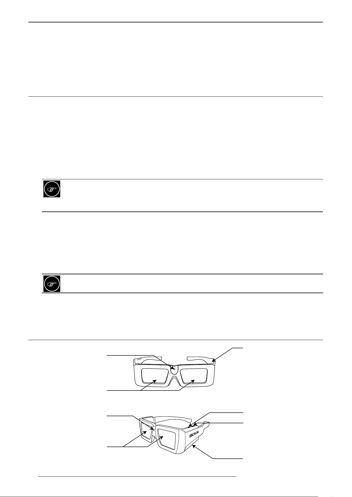
9.3 Operating the 3D Glasses
Indicating LED (A)
Optical Lenses (C)
Indicating LED (A)
(B) Power button
(D) 3 positions button
28
Optical Lenses (C)
(E) micro USB slot
RF 3D Glasses
R599870 - Force 4K User Manual
Page 29

INSTALLATION
Charging the 3D Glasses
The 3D Glasses come with a USB rechargeable battery that is charged using the USB to micro USB cable.
Connect the cable to the micro USB slot (E). The indicating LED (A) will light On red continuously during the
charge. The glasses are fully charged when the indicating LED (A) switches Off.
Turning On your 3D Glasses
• Press the Power Button (B) once.
• The indicating LED (A) will light On and the Optical Lenses (C) will blink alternately left and right to indicate
that they are ready to synchronize with the 3D synchro emitter.
Turning Off your 3D Glasses
To turn Off the glasses, press and hold the Power button (B) for 3 seconds until the indicating LED (A) switches
Off.
3D Glasses battery level
The battery allows up to 75 hours of continuous power. A low power level, below 30%, is indicated by a single
flash of the Indicating LED (A) at the 3D glasses switch On. Power level between 30% and 90% is indicated by 2
flashes. 3 flashes indicates that the power is above 90%
Auto Power Off
The 3D Glasses are programmed to automatically stop functioning after 5 minutes of immobilization or 10 minutes
without a 3D synchro signal. To turn them back On, just press the Power Button (B) once.
10.0 INSTALLATION
10.1 Installation Mode
An Installation Mode is a memory slot that collectively manages the setting values of “Lens Control”, “Pixel
Adjust”, “Mask”, “Anamorphic” and “Screen Adjust”. There are a total of 10 Installation Modes.
Mode Select
Selects a specific memory amongst the 10 available. Setting values can be set from Mode 1 up to Mode 10.
Name Edit
Each Installation Mode can be renamed using “Name Edit”. You can use up to 10 characters that can be alphabets
(upper or lower case), numeric characters and/or symbols.
Mode Copy
The Mode Copy can be used to easily duplicate a selected Mode into the current Mode. Select the mode to copy
to and press the [OK] button to confirm.
10.2 Lens Control
Focus / Zoom / Shift
Adjust the lens focus / Zoom or Shift to obtain a clear picture.
Image Pattern
If set to On, an internal pattern will be generated to adjust the current setting. If you want to use an external
generator, turn this option to Off.
Lock
Once the Lens is correctly set, you may lock this setting menu by turning the Lens control Lock to On. Any attempt
to access the Lens control menu will lead to the display of a warning message.
Lens Center
Reset the lens position to the original, central position.
R599870 - Force 4K User Manual 29
Page 30
INSTALLATION
10.3 Pixel Adjust
Adjust
Disables with the setting Off, to enable the pixel adjustment turn this setting to On.
Adjust Area
Whole: the entire screen is selected for adjustment.
Zone: the screen is divided into 121 adjustment zones.
Adjust Color
Select the color to adjust: Red or Blue. The green color is fixed.
Adjust Pattern
Enables a third party adjust pattern to be used for pixel alignment.
Adjust Pattern Color
Select a pattern to help the pixel alignment. Settings: White or Green+adjusting Color. Yellow for red, Cyan for
blue.
Adjust (Pixel)
This function is enable when the Adjust Area is set to Zone only. You can adjust the selected color position
horizontally and vertically by 1-pixel steps.
• H settings: -2 +2
• V settings: -2 +2.
Adjust (Fine)
Use this function to move the selected color within smaller steps.
• H settings: -31 +31
• V settings: -31 +31
Reset
Reset all pixel adjustments to default factory settings.
RCU SHORTCUTS DURING PIXEL ADJUSTMENT:
[GAMMA] button on the RCU switches adjust color parameter between Red and Blue.
[PIC. ADJ.] button on the RCU switches the adjust area parameter between whole and zone. At the same
time, the zone cursor will appear on the adjust pattern.
[COLOR SPACE] button on the RCU changes the adjust pattern from white to green+adjust color.
Use the [COLOR TEMP] button on the remote control to change adjustment method from Pixel to Fine
tune and switch to the fine tune window.
[BACK] button will exit the Pixel Adjust mode.
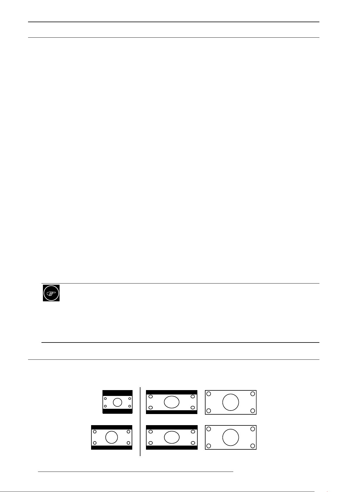
10.4 Anamorphic
• Off: No modification to original picture.
• Mode A: The picture is vertically stretched to fit an installation with anamorphic lens. A cinemascope picture
is stretched to completely fill the panels without black bands, using the optimum resolution and brightness.
30
2.35:1 source with lens Mode A with lens
Anamorphic Mode A.
R599870 - Force 4K User Manual
Page 31
DISPLAY SETUP
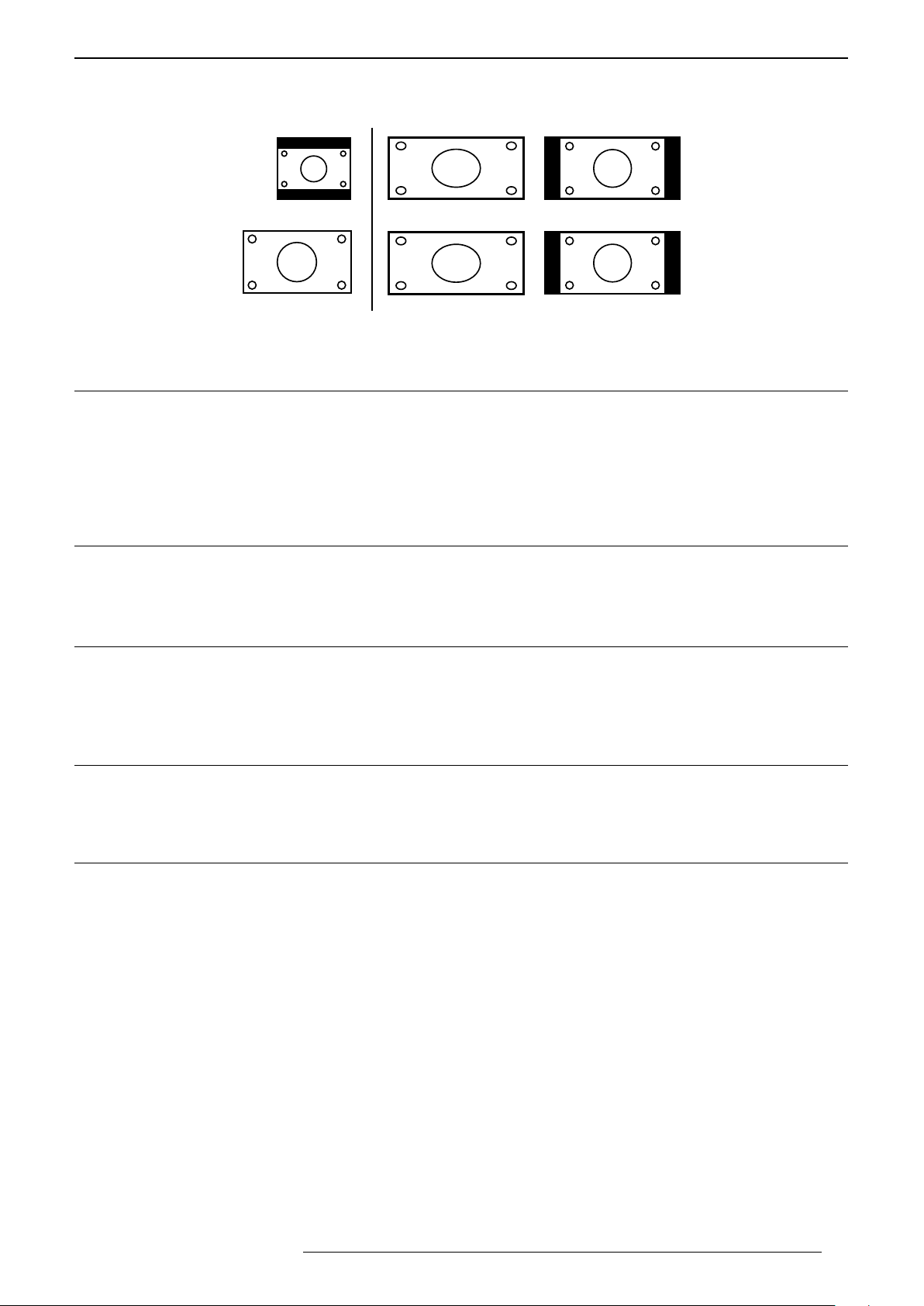
• Mode B: This setting squeezes horizontally the picture to fit a 16:9 image into a cinemascope screen. This
setting is to be used with an anamorphic installation where the lens is permanently fixed in front of the unit
and to watch 16:9 content in its original format.
16:9 source with lens
Anamorphic Mode B
Mode A with lens
10.5 ScreenAdjustandScreenNo.
This setting corrects the color balance derived from the reflective characteristics of the screen without altering the
global picture settings. You may select the best template available in the Screen No.
a) 001 - 009: select a profile between 001 and 009 when watching 3D content with 3D shutter glasses. Profile
001 is recommended when using Cineversum’s active 3D glasses.
b) 010 to 255: select the best compensation profile depending on your screen and environment.
10.6 Installation Style
Flip the image to the left or right, up or down according to the projection state of the projector:
Front, Ceiling Mount (F), Rear or Rear Ceiling mount (R)
10.7 Keystone
Compensate for trapezoidal distortion caused by installation. Independently to the screen orientation, make sure
that the projector is not tilt more than 5% up/down. This setting cannot be used if “Pincushion” is set.
• Vertical Keystone from -16 to +16.
10.8 Pincushion
Corrects the geometric distortion that occurs when projecting on a curved screen. Pincushion can be set to from
0 up to 16 (more correction). This function cannot be used if “Keystone” is set
10.9 High Altitude Mode
Select this when the projector is in a location of low atmospheric pressure. On or Off
11.0 DISPLAY SETUP
Back Color
Configures the screen color displayed when there is no active input. Set to Blue or Black.
Menu Position
Upper left, Upper right, Center, Lower right, Lower left.
Signal Display
On: Display the source of the input signals after input selection. Off: Don’t display.
Logo
On: Display D-ILA logo during startup for 5 seconds. Off: Don’t display.
R599870 - Force 4K User Manual 31
Page 32

FUNCTION
Language
Choose the OSD language between: English, Japanese, German, Spanish, Italian, French, Portuguese, Dutch,
Swedish, Norwegian, Russian and Chinese.
12.0 FUNCTION
12.1 Trigger
The 12V trigger output can be used to control any compatible devices such as motorized screens or anamorphic
kits: The 12V trigger output is 12Vcc, 100mA. Select the trigger output behavior:
• Off: 12V trigger voltage state is always low.
• Power: 12V trigger state is high when the projector is powered ON. To be used with motorized screens.
• Anamo: 12V trigger is high only when Anamorphic Mode A or Mode B is engaged. To be used with motorized
anamorphic kits.
• Inst. Mode 1 up to 10: 12V trigger state is high when the selected Installation Mode is the same as the Mode
number configured.
12.2 Off-Timer
You can configure this automatic power Off function that will switch off the projector when there is no operation
or after a determined timer. Choose the duration of the timer between: Off, 1 hour, 2 hours, 3 hours and 4 hours.
12.3 ECO Mode
This setting when set to On will minimizes the power consumption in the Standby Mode. Additionally, it will
automatically switch Off whenever the input signal is interrupted for 20 min. Must be Off to operate this unit from
Standby Mode with RS-232, LAN communications or Control4 protocols.
12.4 Network
When the Communication Terminal selected is LAN, this unit will be visible on the local Network and the following
parameters need to be configured. Refer to next section for more info.
12.5 Remote Code A or B
Select in the projector menu the code A or B according to the code selected on the RCU. You can change the code
used by the RCU to communicate with the projector from A to B. To do so, press and hold for 3 sec simultaneously
[MENU]+[BACK] buttons on the RCU. All the buttons on the RCU will blink.
• Two blinks indicate that B code is used.
• Three blinks indicate that A code is used.
12.6 Hide Mode
This setting is used to temporarily hide the current image by switching Off the Laser alimentation. You can also
use the [Hide] button on the RCU to set this function.
12.7 FactoryReset
Confirm to reset all this unit settings to default settings at once.
12.8 SoftwareUpdate
Confirm to start the update procedure. Make sure that a valid software file must be loaded on an USB stick and
that this stick is fully inserted in the USB/Update input located at the rear of this unit.
32
R599870 - Force 4K User Manual
Page 33

13.0 INFORMATION MENU
Input Terminal
Displays the active video input.
Input Source
Displays the type of the current video input signal.
Resolution
If the active input is PC input, its resolution is displayed.
H. and V. Frequency
In the case of PC signal, the horizontal and vertical frequencies are displayed.
Color Depth
Displays the color bit depth of the input video signal.
Colorimetry
Displays the color space and color depth of the input signal.
INFORMATION MENU
HDR
Displays if the source uses the HDR encoding or not.
Light source time
Displays the accumulated hours of usage of the lamp.
14.0 CINEMASCOPE SETUPS
14.1 LensZoomorStaticCinemascopekit
The centralizes the controls and automation commands for a unique, versatile and unexpectedly simple to operate
2.35:1 theatre experience using Lens Zoom or the Static Cinemascope kit.
• Up to 10 lens position memories when using Installation Mode 1 up to Mode 10.
• Integrated Constant Image Width (CIW) scaler using anamorphic mode A and mode B.
• Dedicated commands to control the Static Cinemascope kit and picture size on a 2.37:1 screen.
14.2 CinemascopesetupusingthelensZoom
Select “Menu => Installation => Mode 1”
Zoom in, until the left and right borders of the picture fits the 2.37:1 screen borders. Save the lens position in the
Installation Mode 1. You can also edit the memory 1 name to “Cinemascope”.
Select “Menu => Installation => Mode 2”
Switch the current Installation Mode from Mode 1 to Mode 2. Make sure to project a 16:9 picture, zoom out until
the picture top and bottom fit the top and bottom of the screen. Adjust the focus and offset if required, then save
this position into the Installation Mode 2. You can additionally edit the memory name to “Standard”.
Switch format using the Remote Control Unit.
You can now switch between Cinemascope and standard formats easily by using the Installation [Mode] buttons
on the RCU and selecting the lens configuration according to the source format.
You can access directly on the remote control unit (RCU) only to the 3 first Installation Modes. If you need
to access to more Modes, you must use the main Menu or access them through automation.
R599870 - Force 4K User Manual 33
Page 34
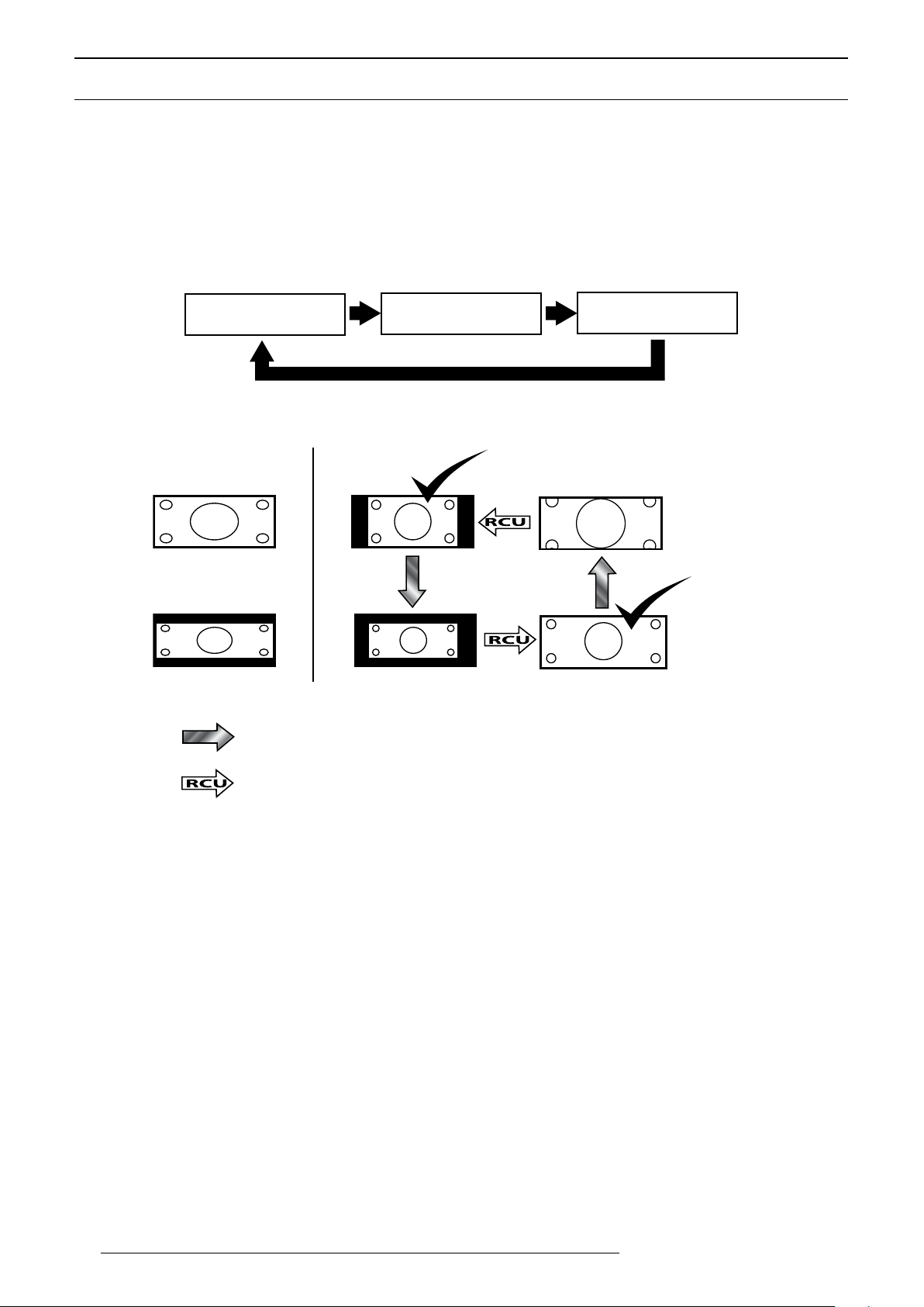
CINEMASCOPE SETUPS
Anamo Kit installed
14.3 Installinga2.35:1screenwiththeStaticCinemascopekit
Video source is 16:9: set [Anamo]rphic to Off
When you select a 16:9 input choose the anamorphic OFF to obtain move the anamorphic lens out. Menu
“Installation => Anamorphic => Off”
Video source is Cinemascope: set [Anamo]rphic to Mode A
Select Anamorphic mode A for this input in the menu Input “Installation => Anamorphic => Mode A”.
[Anamo]rphic modes
OFF Anamo Mode A Anamo Mode B
When you press sequentially the [Anamo]rphic button, you change the mode from OFF, Mode A and Mode B.
• Mode A is intended to be used with an anamorphic lens to watch 2.35:1 content on a 2.35:1 screen.
• Mode B is intended to be used to watch 16:9 content on a 2.35:1 screen and with the Static Cinemascope kit.
2.35 screen
Mode B
Mode B
16:9 on 2.35 screen
2.35 on 2.35 screen Mode A
16:9 format
2.35:1 format
Mode A
When the source switches format....
... press [Anamo] button to obtain the correct anamorphic mode.
34
R599870 - Force 4K User Manual
Page 35
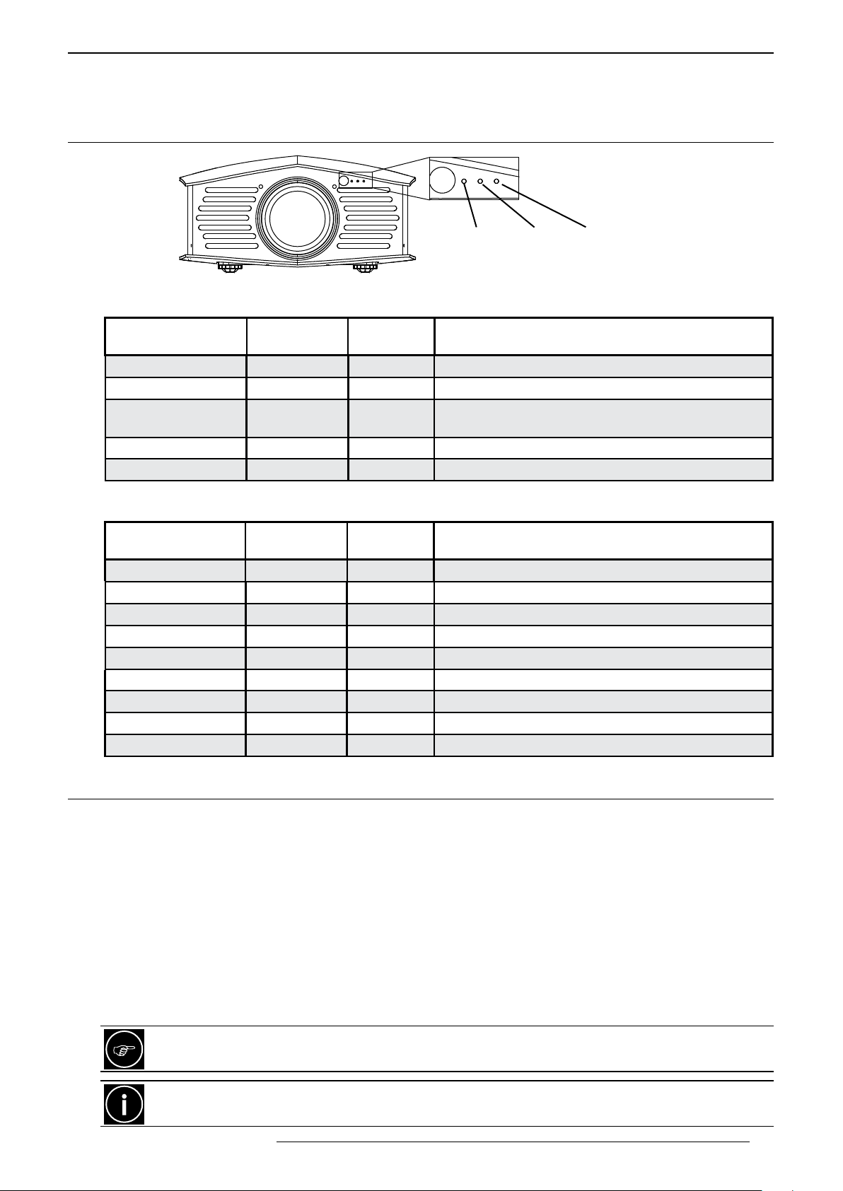
15.0 MAINTENANCE
15.1 LEDsindicators
LED indicator during normal operation
MAINTENANCE
Standby/On - Light - Warning
STANDBY/ON
(Green or Red LED)
On Red Off Off The unit is in standby mode
On Green Off Off This unit is starting up
Off Off Off During projection or
Blinking Green Off Off The picture is temporarily hidden (Hide is On)
Blinking Red Off Off This unit is shutting down (cool-down) mode
LIGHT
(Orange LED)
WARNING
(Red Led)
OPERATION
Standby mode and ECO mode is set
LED indicator malfunction warnings
STANDBY/ON
(Green or Red LED)
On/Blinking On/Blinking On/Blinking This unit processing a software update
Off Off Blinking 1x Software update failed, please check USB card
Off Off Blinking 2x Cooling fan stopped abnormally
Off Off Blinking 3x Internal temperature is abnormally high
Off Off Blinking 4x External temperature is abnormally high
Off Blinking Blinking Abnormal circuit operation
Off Blinking 1x On Abnormal circuit operation
Off Blinking 3x On Abnormal circuit operation
Off Blinking 4x On Safety switch activated, maintenance check is required
LIGHT
(Orange LED)
WARNING
(Red Led)
OPERATION OR WARNING
15.2 Cleaning dust Filter
The filters must be cleaned regularly to allow an efficient air intake. Otherwise, dirt may enter the unit and appear
as shadows on the screen. If dirt has entered the unit or if you need information about the filter, please consult
your authorized dealer.
Cleaning procedure
• Pull out the power plug from the outlet while the projector is in standby mode.
• Loosen the 4 screws and remove the cover
• Remove the sponge filter
• Use a vacuum cleaner to remove dirt from the sponge filter carefully
• Restore the sponge filter
• Restore the cover and fasten the 4 screws.
Do not wash the air filter with water. Doing so may cause the filter to deteriorate. Make sure to attach the
air filter first and sponge filter last to ensure the best dust filtration possible.
If you need to replace the Air Filter (RZ201741) or Sponge Filter (RZ201742) because they are broken or
if they are too dirty please contact your re-seller or the nearest Cineversum distributor.
R599870 - Force 4K User Manual 35
Page 36
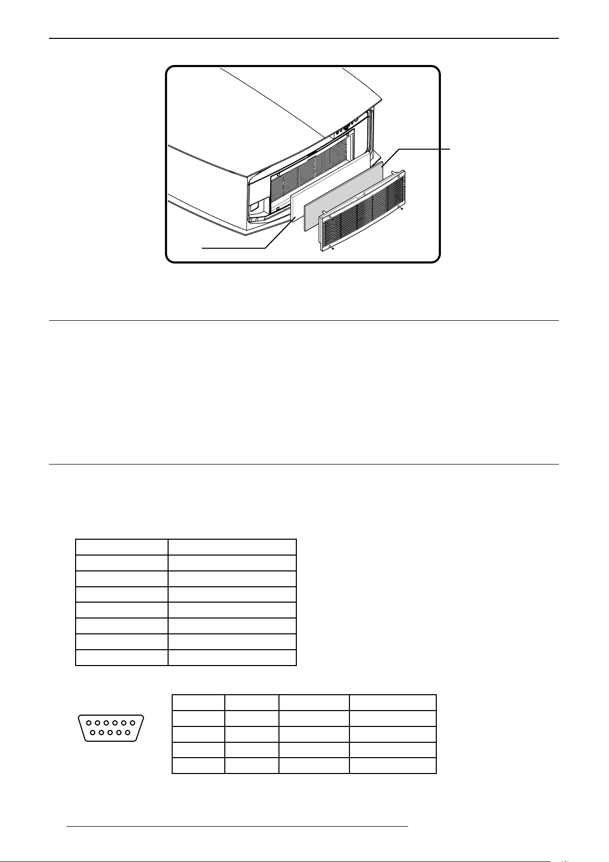
APPENDIx
Air Filter (white)
Remove and clean both the air and sponge lters.
15.3 Dirt on the Lens
Sponge Filter (grey)
The lens shall be cleaned using commercial blowers or lens cleaning papers (for cleaning glasses and cameras).
Do not use fluid-type cleaning agents. This may lead to peeling of the surface coating film. The lens surface is
fragile. Avoid rubbing it hard or knocking.
16.0 APPENDIX
16.1 RS-232Cprotocol
Serial communication specifications
Control of this unit is possible using a computer or automation device connected with a RS-232 cross cable
(female - female D-sub 9 pins cable) or LAN/ RJ-45 cable. Communication specifications for this unit are as
follows:
Baud Rate 19200 bps
Data Format Binary
Mode Asynchronous
Parity None
Start Bit 1 bit set to high
Stop Bit 1 bit set to low
X on/off None
Flow Control None
RS-232C pin assignation
1
6
36
5
9
Pin Signal Function Signal Direction
2 RxD receive data PC -> this unti
3 TxD transmit data this unit -> PC
5 GND ground -
1, 4, 6-9 NC - -
R599870 - Force 4K User Manual
Page 37
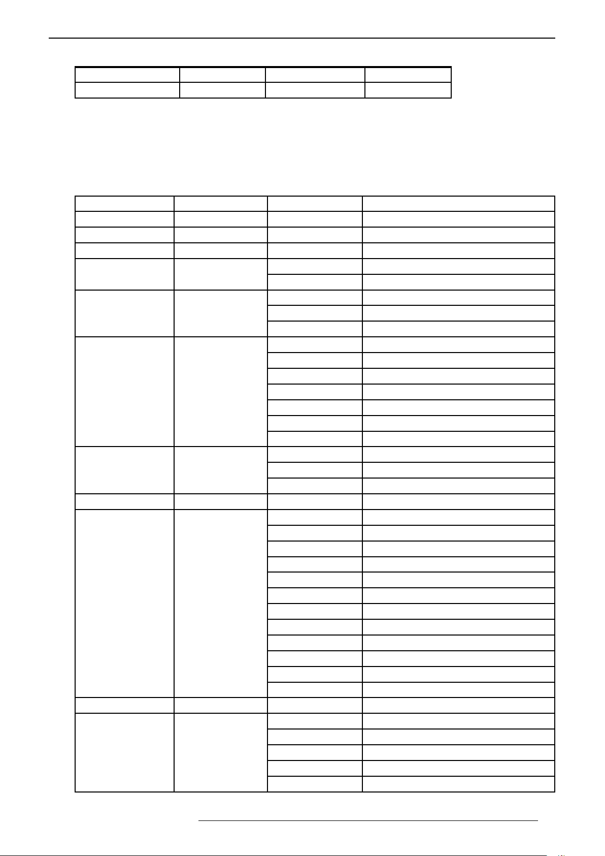
APPENDIx
Command Format
Header 1 Header 2 Command Command Data End of Data
21h 89h 01h 2 bytes 2 to 4 bytes 0Ah
Header 1 : 21h for operating commands or 3Fh for reference command.
Header 2 fixed to 89h 01h
Command: 2 bytes length
Command Data: variable length between 2 and 4 bytes
End of Data fixed to 0Ah
Available Operating commands
Function Command Command Data Description
Connection check 00h 00h none Check the connection in standby mode
Power 50h 57h 30h / 31h Switch Off (Standby mode) / On.
Inputs 49h 50h 36h / 37h Switch active input to HDMI1 / HDMI2
Power /w confirm 52h 43h 37h 33h 30h 35h Switch this unit On.
37h 33h 30h 36h Switch this unit Off. (send twice)
Switch input 52h 43h 37h 33h 30h 38h Switch to next input
37h 33h 37h 30h Switch input to HDMI1
37h 33h 37h 31h Switch input to HDMI2
Keypad 52h 43h 37h 33h 30h 31h UP
37h 33h 30h 32h DOWN
37h 33h 30h 33h BACK
37h 33h 32h 45h MENU
37h 33h 32h 46h OK
37h 33h 33h 34h RIGHT
37h 33h 33h 36h LEFT
Hide Display 52h 43h 37h 33h 31h 44h Toggle Hide On/Off
37h 33h 44h 30h Switch Hide to On
37h 33h 44h 31h Switch Hide to Off
OSD Menu Position 52h 43h 37h 33h 34h 32h Toggle the OSD menu position
Picture Modes 52h 43h 37h 33h 36h 38h Cinema Mode
37h 33h 36h 41h Film Mode
37h 33h 36h 41h Natural Mode
37h 33h 45h 44h HDR Mode
37h 33h 36h 43h USER 1 Mode
37h 33h 36h 44h USER 2 Mode
37h 33h 36h 45h USER 3 Mode
37h 33h 36h 46h THX Mode
37h 33h 43h 41h USER 4 Mode
37h 33h 43h 42h USER 5 Mode
37h 33h 43h 43h USER 6 Mode
37h 33h 46h 34h Toggle picture mode Menu
Low Latency 52h 43h 37h 33h 46h 38h Toggle Latency Mode value
Installation Mode 52h 43h 37h 33h 44h 38h Installation Mode 1
37h 33h 44h 39h Installation Mode 2
37h 33h 44h 41h Installation Mode 3
37h 33h 45h 35h Installation Mode 4
37h 33h 45h 36h Installation Mode 5
R599870 - Force 4K User Manual 37
Page 38
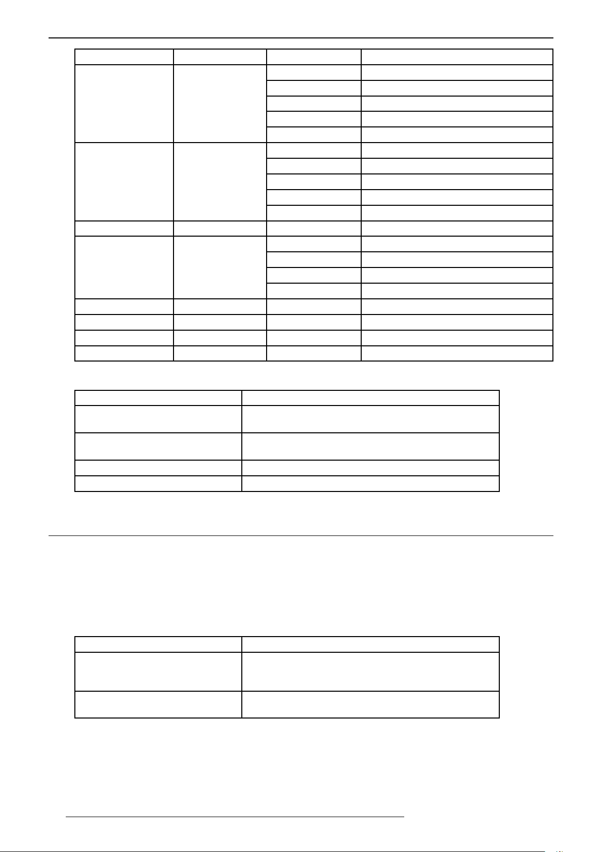
APPENDIx
Function Command Command Data Description
Installation Mode 52h 43h 37h 33h 45h 37h Installation Mode 6
37h 33h 45h 38h Installation Mode 7
37h 33h 45h 39h Installation Mode 8
37h 33h 45h 41h Installation Mode 9
37h 33h 45h 42h Installation Mode 10
Expert Calibration
(THX)
3D Format menu 52h 43h 37h 33h 44h 36h Toggle the 3D Format menu
Anamo 52h 43h 37h 33h 43h 35h Toggles the Anamorphic mode
Lens Control menu 52h 43h 37h 33h 33h 30h Toggle the lens control menu
Lens Aperture menu 52h 43h 37h 33h 32h 30h Toggle the lens aperture menu
MPC menu 52h 43h 37h 33h 46h 30h Toggle the MPC menu
CMD menu 52h 43h 37h 33h 38h 41h Toggle the CMD menu
52h 43h 37h 33h 43h 36h THX plus - On and Adjust
37h 33h 43h 37h THX plus - Off
37h 33h 43h 38h THX plus - On locked
37h 33h 38h 35h Switch Picture Mode to THX - Bright
37h 33h 38h 36h Switch Picture Mode to THX - Dark
37h 33h 32h 33h Switch Anamorphic mode to A
37h 33h 32h 34h Switch Anamorphic mode to Off
37h 33h 32h 42h Switch Anamorphic mode to B
Examples
You want to... Command to send
Switch this unit On send: 21h 89h 01h 50h 57h 31h 0Ah
receive: 06h 89h 01h 50h 57h 0Ah
Switch this unit Off send: 21h 89h 01h 50h 57h 30h 0Ah
receive: 06h 89h 01h 50h 57h 0Ah
Change active Input to HDMI2. send: 21h 89h 01h 52h 43h 37h 33h 37h 31h 0Ah
Change Picture Mode to match HDR send: 21h 89h 01h 52h 43h 37h 33h 45h 44h 0Ah
16.2 LAN Control
Sending a LAN Control Command
In order to send a Remote Control compatible command to this unit, you must open a TCP connection on port
20554. and send a command immediately as the connection will be dropped within 5 sec of inactivity. If for any
reason you have to change the TCP connection port, you may use the following RS-232c/LAN command.
[4Ch 53 50h 54h] + 4 ASCII chars as new port address in hexa
You want to set TCP port to 10000 Command to send
Send 10000 as new TCP port value:
10000 is 2710h in hexa, converted in
ASCII characters: 32h 37h 31h 30h
Then, reboot Network module send: 21h 89h 01h 4Ch 53h 52h 53h 0Ah
send: 21h 89h 01h 4Ch 53h 50h 54h 32h 37h 31h 30h 0Ah
receive: 06h 89h 01h 4Ch 53h 0Ah
receive: 06h 89h 01h 4Ch 53h 0Ah
38
R599870 - Force 4K User Manual
Page 39
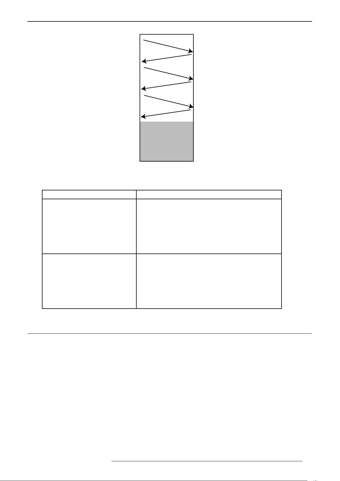
Projector
`Control Device
Examples
1. Opening Connection
on port 20554
3. Command Type
(PJREQ)
5. Command
After 5sec,
connection is closed
LAN communication protocol and timed out
APPENDIx
2. Projector Ready
(PJ_OK)
4. Projector Acknowledge
(PJACK)
6. Projector confirms
You want to... Command to send
Switch this unit On 1. open TCP connection
2. receive PJ_OK: 50h 4Ah 5Fh 4Fh 4Bh
3. send PJREQ: 50h 4Ah 52h 45h 51h
4. receive PJACK: 50h 4Ah 41h 43h 4Bh
5. send Power On cmd:
21h 89h 01h 52h 43h 37h 33h 30h 35h 0Ah
6. receive confirmation: 06h 89h 01h 52h 43h 0Ah
after 5 sec, TCP connection is closed.
Switch Anamorphic to mode A 1. open TCP connection
2. receive PJ_OK: 50h 4Ah 5Fh 4Fh 4Bh
3. send PJREQ: 50h 4Ah 52h 45h 51h
4. receive PJACK: 50h 4Ah 41h 43h 4Bh
5. send Anamorphic A:
21h 89h 01h 52h 43h 37h 33h 32h 33h 0Ah
6. receive confirmation: 06h 89h 01h 52h 43h 0Ah
after 5 sec, TCP connection is closed.
16.3 InfraRed,longhex-prontocompatibleRCU
The infrared command must be sent using NEC 5 protocol in ASCII format.
In the following example, Power ON command is 37h 33h 30h 35h, this command has to be converted as ASCII,
it becomes 73 05.
To send this command using long hex Pronto compatible, convert the ASCII code as two hexadecimal numbers
as follow:
Code A: 73h = 115 (for code B: 63h = 99, replace 115 by 99)
05h = 5
Then program the Pronto RCU using the Device number 115 and Function 5:
Device Code: 115 (0x73) Function: 5 (0x05):
0000 006D 0001 0011 0141 00A0 0014 003C 0014 003C 0014 0014 0014 0014 0014 003C 0014 003C 0014
003C 0014 0014 0014 003C 0014 0014 0014 003C 0014 0014 0014 0014 0014 0014 0014 0014 0014 0014
0014 0336
Ask your dealer for a complete device/function chart with their corresponding long hex commands.
R599870 - Force 4K User Manual 39
Page 40
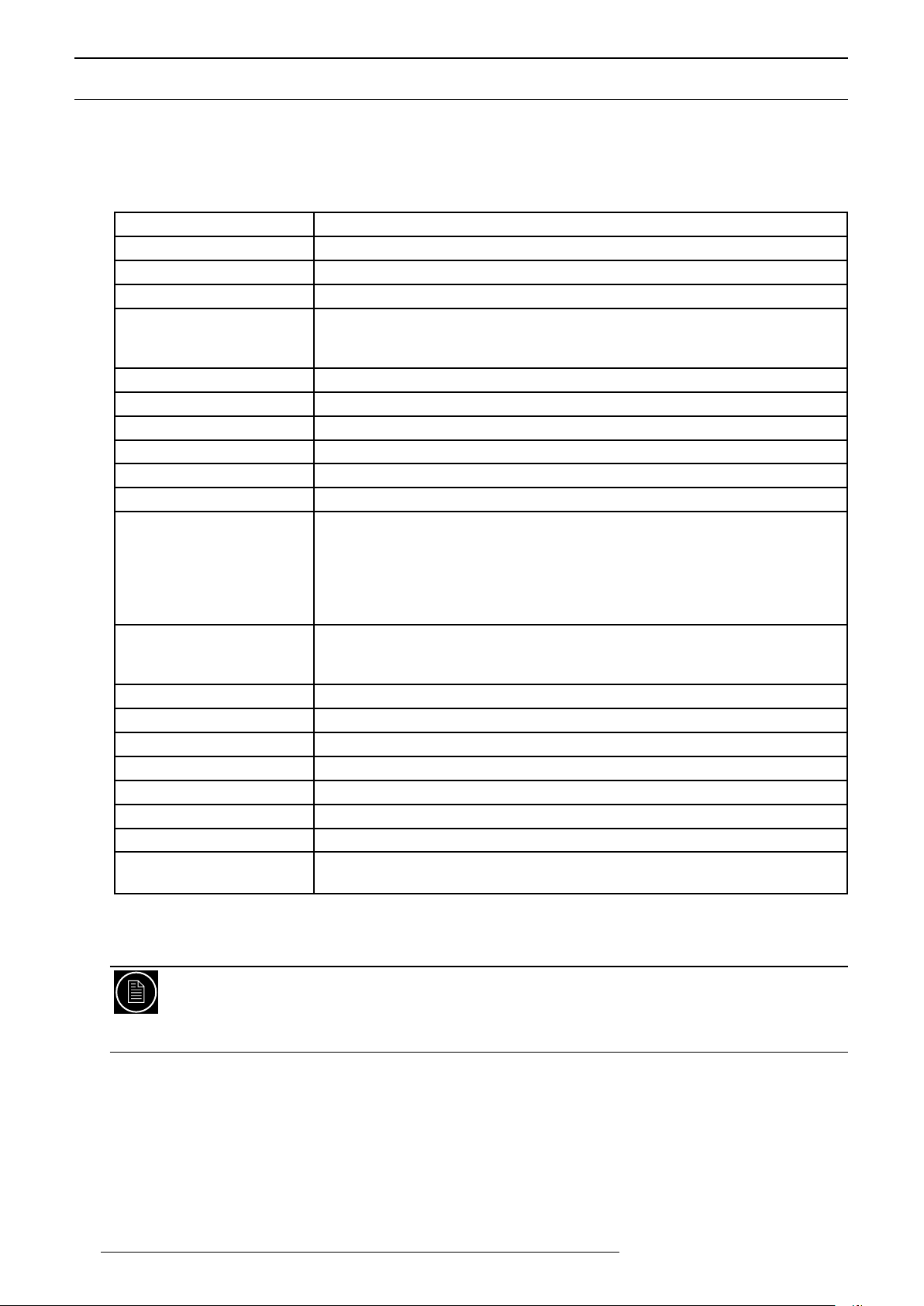
APPENDIx
16.4 Specications
Overview
The Force 4K uses the latest technology developed to provide the ultimate video-projection experience. LCoS
(Liquid Crystal on Silicon) technology based on a reflective principle features an extremely high-definition picture
and seamless color gradations.
Emission method
Display panel size
Panel Resolution
High Contrast ratio
Projection lens
Brightness
Screen size
Distance range
Inputs:
HDMI 1
HDMI 2
Video Processing
Light source lamp
Power Requirements
Power Consumption
Noise (SPL)
Unit size (W x D x H)
Net Weight
Box size (W x D x H)
Gross Weight
Operation Environment
• Design and specifications are subject to change without prior notice.
• Please note that some of the pictures and illustrations may have been abridged, enlarged in order to aid
comprehension. Images may differ from the actual product.
LCoS (Reflective Active Matrix Principle)
3x 0.69” LCoS panels
D-Cinema 4K - 4096 x 2160 pixels
infinite:1
Throw ratio 1.37:1 - 2.77:1 with 2x Zoom
Electronic zoom, focus
Motorized lens shift +/- 100% vertically, +/-42% horizontally.
3000 ANSI Lumens
60” to 250” (Aspect ratio 16:9)
from 150cm to 1200cm
HDMI 2.0a with HDCP2.2 - 4K and HDR up to 18 Gbps
HDMI 2.0a with HDCP2.2 - 4K and HDR up to 18 Gbps
4K MPC enhancement, Detail Enhancement,
Blur Reduction with Motion Enhancement
Full 4K RGB 36bits per pixel
HDR with PQ gamma (HDR10) or HLG (Hybrid Log Gamma)
Smart Laser Power Level Management (SLPLM™)
Low Latency mode (< 3 frames)
Laser Phosphor Light Source module
3x banks of 8 Laser LED modules
20,000 hours lifetime
100V - 240V AC, 50Hz/60Hz
750 W max
25 dB(A) in Low LD mode
72 x 50 x 23,5 cm - 28.3" x 19.7" x 9.3" (excluding feet)
45 kg - 99.0 lbs
90 x 81 x 50 cm - 35.4" x 31.9" x 19.7"
59 kg - 130 lbs
Temperature: 5°C to 35°C (Storage Temperature: -10°C to 60°C)
Humidity: 20% to 80% without condensation
40
3-CHIP LCOS SYSTEM
LCoS is the abbreviation of Liquid Crystal on Silicon. The 3-Chip LCoS systems feature dedicated panels
for each color channel and render seamless color graduations without any flickering or rainbow effect
artifacts
R599870 - Force 4K User Manual
Page 41
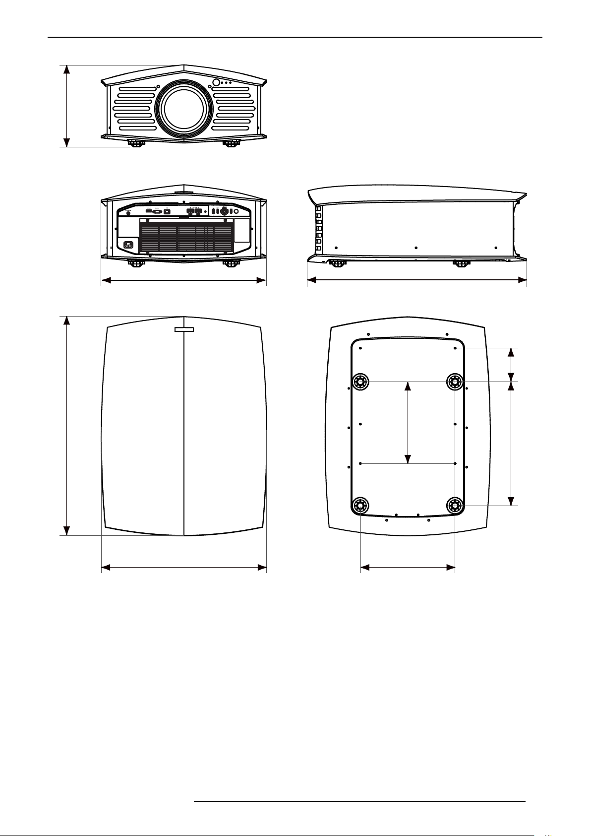
Dimensions
28 cm
11.0”
APPENDIx
78 cm
30.7”
59 cm
23.2”
59 cm
23.2”
78 cm
30.7”
12 cm
29 cm
44 cm
33,7 cm
R599870 - Force 4K User Manual 41
Page 42

42 R599870 - Force 4K User Manual 43
R599870 - Force 4K User Manual
Page 43

Page 44

 Loading...