

Page 1
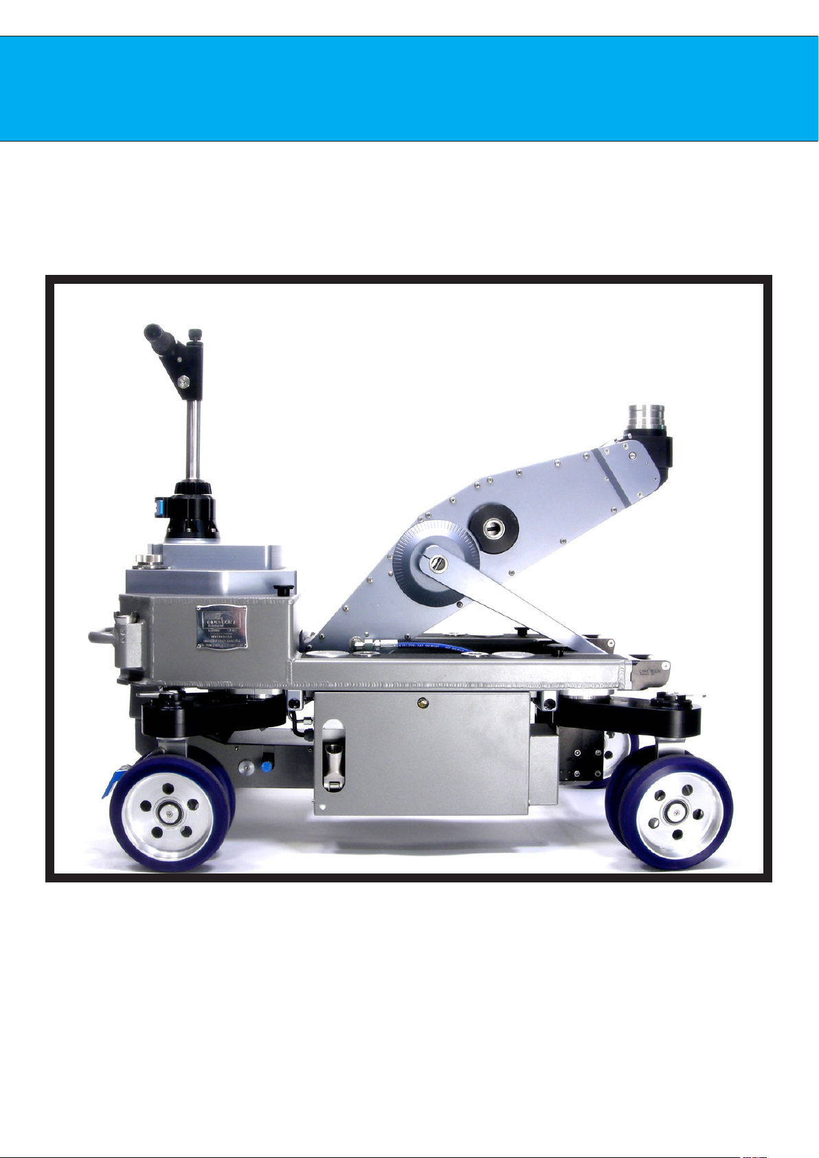
ALBATROSS DOLLY
User Manual
©2019 Cinetech Italiana Srl
Page 2
Page 3

INDEX
USER GUIDE
• Albatros Dolly - pg.6
• Steering system - pg.9
• Small arms - pg.14
• Small arms positions - pg.16
• Hydraulic system - pg.20
• Oil ow regulator - pg25
• Lifting arm - pg.26
• Accessories - pg.28
Page 4

Page 5

User Guide
©2019 Cinetech Italiana Srl
Page 6
User Guide
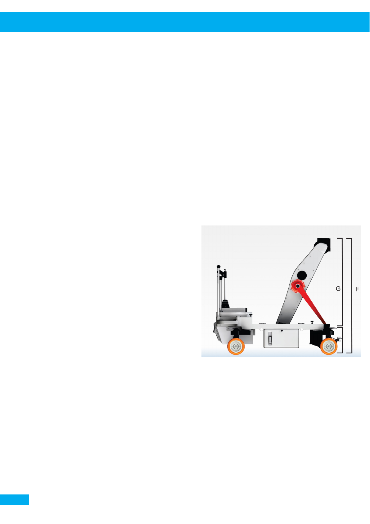
Albatros is a dolly engineered and designed using the latest modern technology
in structural materials and surface nishes built to meet all the needs of profes-
sionals in the world of cinema.
All parts of the Albatross dolly are made
of stainless steel and light aluminum al-
loy. Vertical movements as well as starts
and stops are uid and repeatable.
The Albatross design is extremely robust
and guarantees excellent performance
in all weather conditions. All the components are designed and manufactured
in the Cinetech Italiana factory based in
Rome.
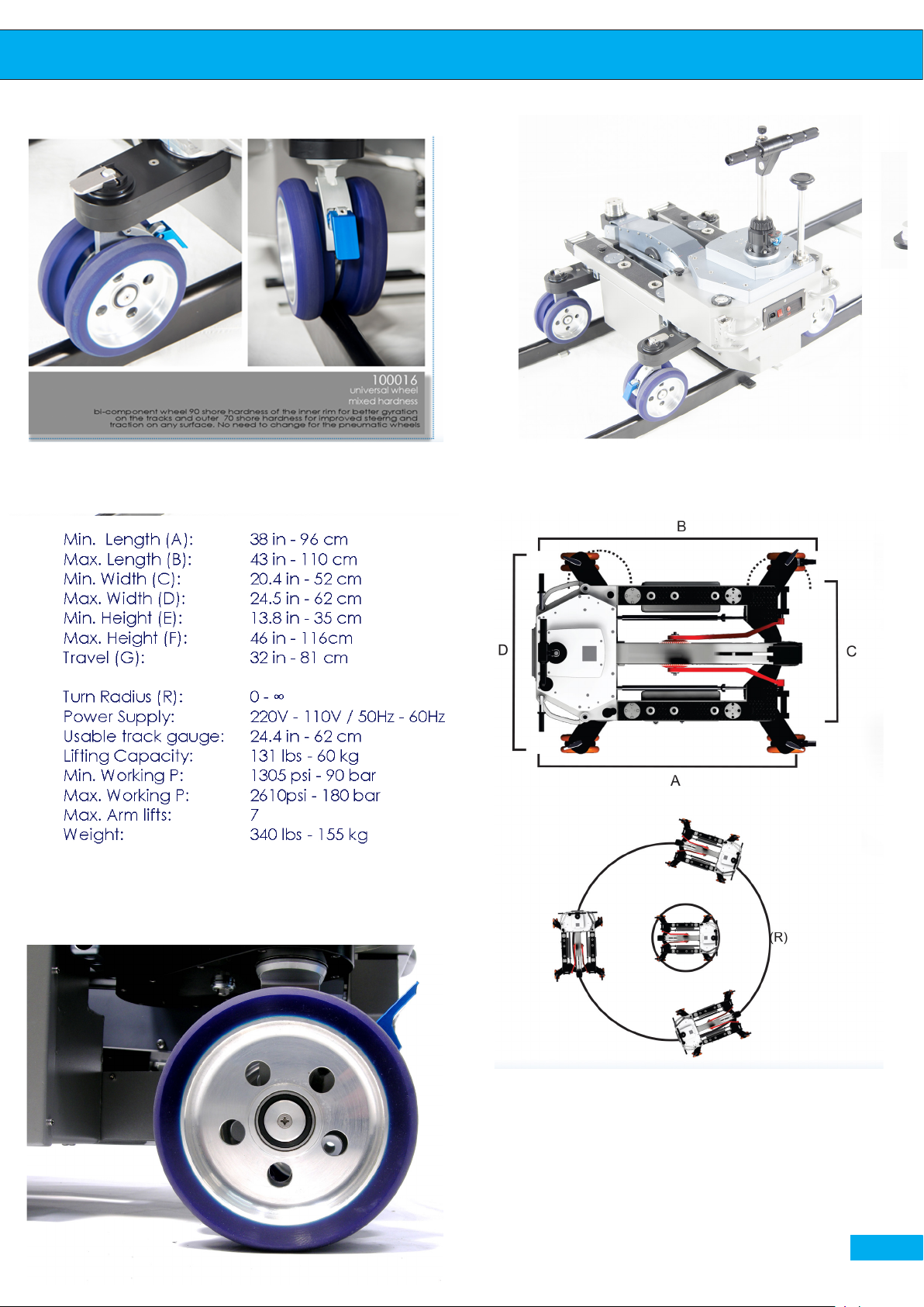
ponent wheels, where the inner rim has
a 90 shore hardness for beer gyration
on tracks, incredible stability and smoothness, while the outer rim has 70 shore hardness for improved steering and
traction on any surface. This feature means more elasticity and crush-proofness,
a concept aiming to eliminate traditional
pneumatic wheels that frequently do
not maintain a proper ination pressure
and consequently stress the entire dolly
structure. Dolly can be equipped with
pneumatic wheels on demand.
A new ow regulation valve allows the
It is possible to choose the following stee-
ring modes:
CRAB: all the wheels are turning at the
same angle, allowing the dolly to have
the longitudinal, transversal and oblique
movements without turning;
ROUND: all the whells are positioned
at dierent angles, thus allowing the
dolly to make the round 360° movement
around its own axis or make the precise
turnaround with an established radius
without the use of the track;
CONV: conventional mode with two rear
wheels steering, so the operator makes a
turn while tracking.
Steering mode change can be made by
simply twisting the steering handle.
Steering system is composed by the hi-
ghly-precise gears and is based between
the rear wheels to facilitate the guidance,
thus avoiding friction.
arm to go faster and without vibrations.
The dolly is equipped with a new piston
that inbodies an end run “dashpot”
A new steering lock allows the dolly
grip to make precise straight moves wi-
thout any extraneous movement of the
wheels, even without using the tracks.
pag. 6
Dolly is equipped with premiere bi-com-
Page 7
User Guide
New bi-component wheel. 70 Shore External Rim - 90 Shore
internal rim
pag. 7
Page 8
User Guide
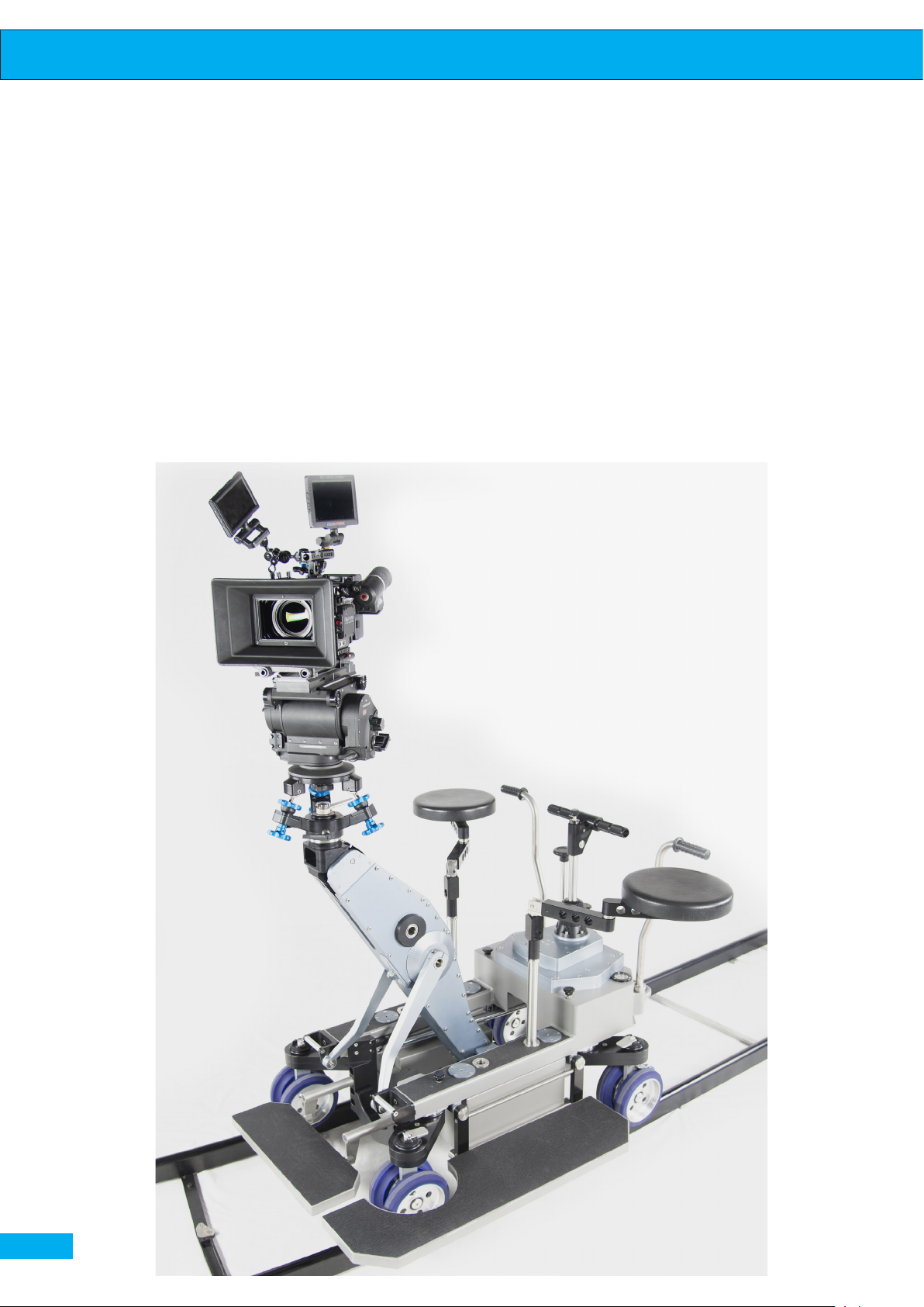
The maximum payload on the Albatros arm is 60 Kg on the head and the height from the
ground is 116 cm. Albatros dolly can work both on the track and on the ground allowing
to the grip and a camera assistant to work owlessly carrying the above mentioned wei-
ght on the head.
The Dolly is composed of several main systems, each of those has a specic function, so
the dolly can go on the ground, on the track and the hydraulic arm can be moved.
pag. 8
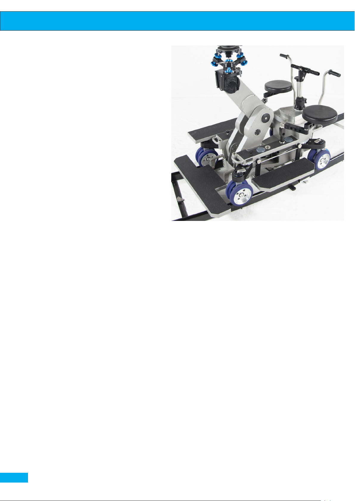
Albatross Dolly on track with standard accessories mounted. Levelling head maxi and camera mounted on the head
Page 9
Steering system
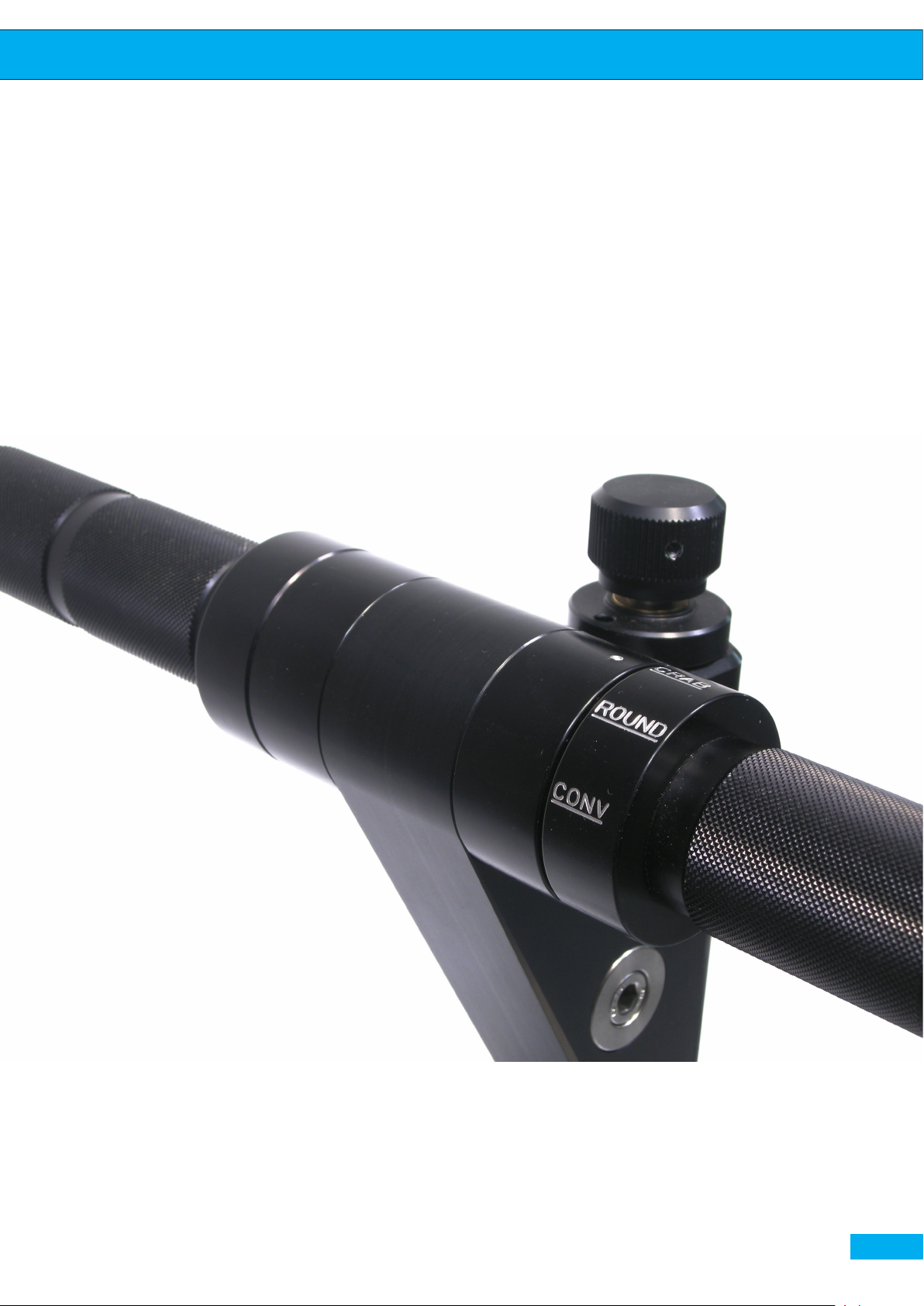
Steering wheel with CRAB, ROUND and CONV steering modes
User Guide
pag. 9
Page 10
User Guide
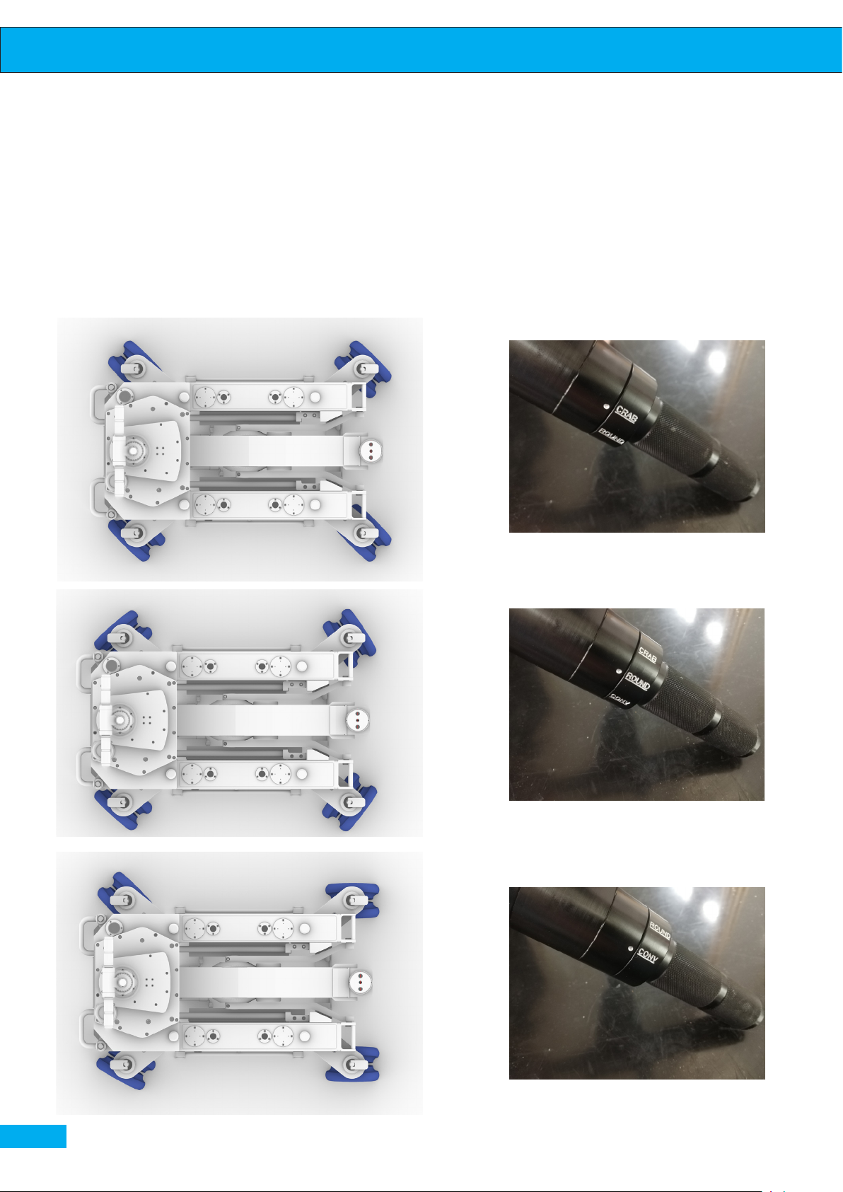
Albatross dolly has the innovative gearbox which is able to transmit the movement to the wheels through a complex gear system. Steering system doesn’t require a lot of maintenance as it is a synchronized system, always in phase for all three
movements (CONV, ROUND, CRAB), guaranteeing reliability over time.
pag. 10
CONV. STEERING MODE CRAB STEERING MODEROUND STEERING MODE
Page 11
User Guide
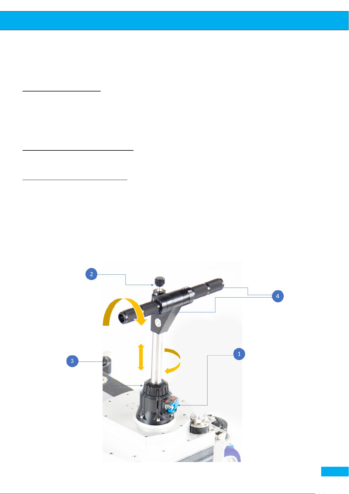
The removable steering column allows simultaneous control of the three synchronized steering modes, changing from CONV to ROUND to CRAB.
Insertion / Extraction
Position the steering column in its compartment on the Dolly, tighten the upper
nut -2- until it stops to connect the column to the steering system. Lock the column by tightening the knurled knob -3To extract the column execute the inverse operation.
Locking of the steering wheel
It is possible to block the steering wheel in central position by locking the lever -1-
Choosing the steering mode
Change of the steering modes can be made by twisting two handles -4- of the steering wheel, thus choosing the steering mode between CRAB, CONV or ROUND.
In order to change the steering mode it is necessery to bring back the steering to
the initial point i.e. with the steering handles set in the position parallel with the
rear side of the dolly and start twisting the handles. Any change of the steering
mode must be made only when the steering wheel is perfectly centered.
The steering has to be smooth and in case the operator doesn’t manage to steer,
it’s not advisable to force the steering.
Steering column. Column lock, gear change rings and knurled fixing ring nut
pag. 11
Page 12
User Guide
pag. 12
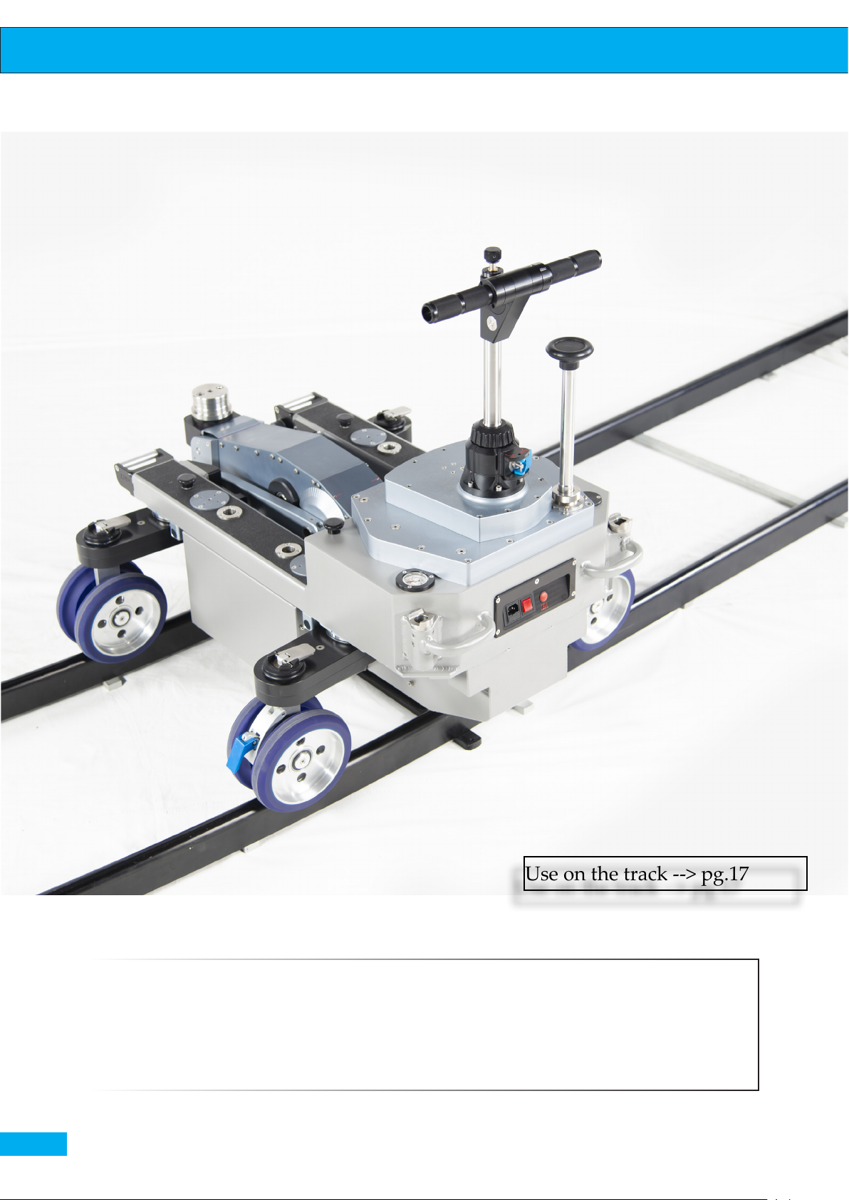
Use on the track --> pg.17
Albatross on the track placed transversely
Albatross dolly can be placed on the track both in the longitudinal and transversal positions.
Page 13
User Guide
pag. 13
Page 14

User Guide
Small arms
The small arms are an integral part of the dolly that serve to increase or
decrease the wheelbase length depending on the width of the track and the
stability when working on the oor. The dolly is equipped with 4 lateral
rotating on 180° arms that can be set in 5 positions, allowing a wide range
of use and easy transportation.
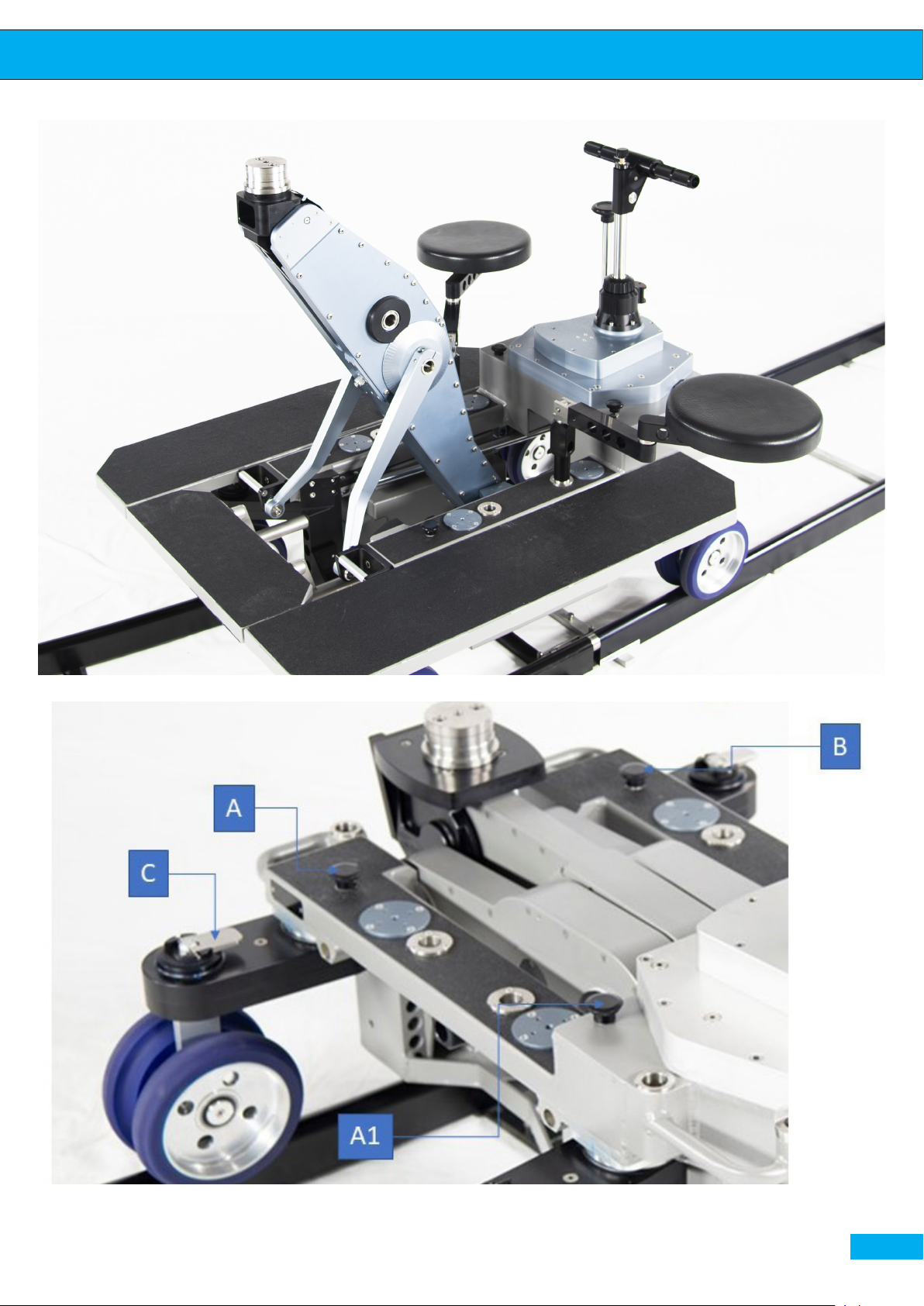
Lifting the grip (A) one can unlock the small arm allowing it to freely turn
around, when the reference marks are aligned it is possible to repress the
grip in order to block the small arm in the desired position. Various positions are available, such as the transport position with the wheels positioned under the dolly, one position for use on the ground and on the track
signed with the mark between two dots, position for shots in narrow environments with the wheels aligned outside (pages 16,19), etc
IMPORTANT: While working on the ground, make sure the small arms
remain in the position signed with the mark between two red dots on the
ring nut which correspond to the ideal calculation of the steering mechanism and that allows the dolly to work at its best.
The lever (C) locks or unlocks only the wheel axis, in fact when the Dolly
has to make a turn on the track it is required to keep all four axis free by
unlocking the four wheels eccentrics, lifting the appropriate levers (C), and
it is also advisable to unlock two arms diagonally (for example front right
and rear left) as explained above.
In the case of the wheel impact, the small arm has a friction system that allows to the wheel to turn freely without damaging the internal parts. In the
case when one or more wheels are turned, or not perfectly straight, when
the steering is in the change position, it is sucient to lift the appropriate
levers (C), realign the wheels and re-tighten.
When the dolly has to work on the curves, one should check that four of
the small arms are in the correct position, i.e. that the four levers (C) are ful-
ly released and two pins (for example A1 e B or opposite combination) are
released diagonally.
pag. 14
The rear wheels are equipped with brakes that must be unlocked in order
to start moving the dolly.
Page 15
User Guide
Left and right side footboards and front footboard.
Locking arm positions
pag. 15
Page 16
User Guide
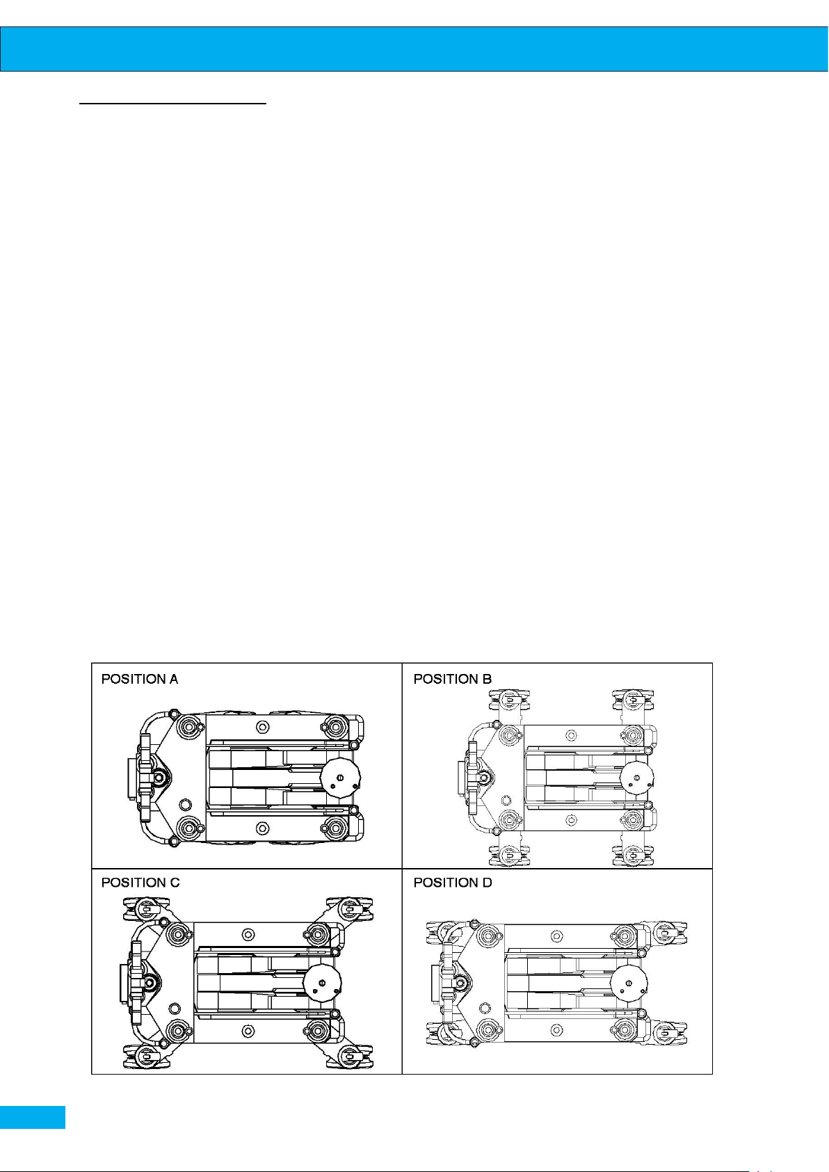
Small arms positions
The default positions are:
1. Position A for transportation: the arms are folded under the Dolly for a minimum footprint.
2. Position B is the ideal position for the maximum stability of the dolly, even if
this position is not ideal to work with the steering system. In this position the
dolly can work on the 620mm track transversally (photo pg.12).
3. Position C when the rear and front small arms are in this position, the dolly
works at its maximum eciency with the steering, allowing the extreme uidity and smoothness of the movement while working on the ground and also on
the 620 mm track.
4. Position D is created to work in the narrow spaces. Dolly can work on the
450mm track in this position.
pag. 16
Diagram of positions of the arms on the dolly structure
Page 17
User Guide
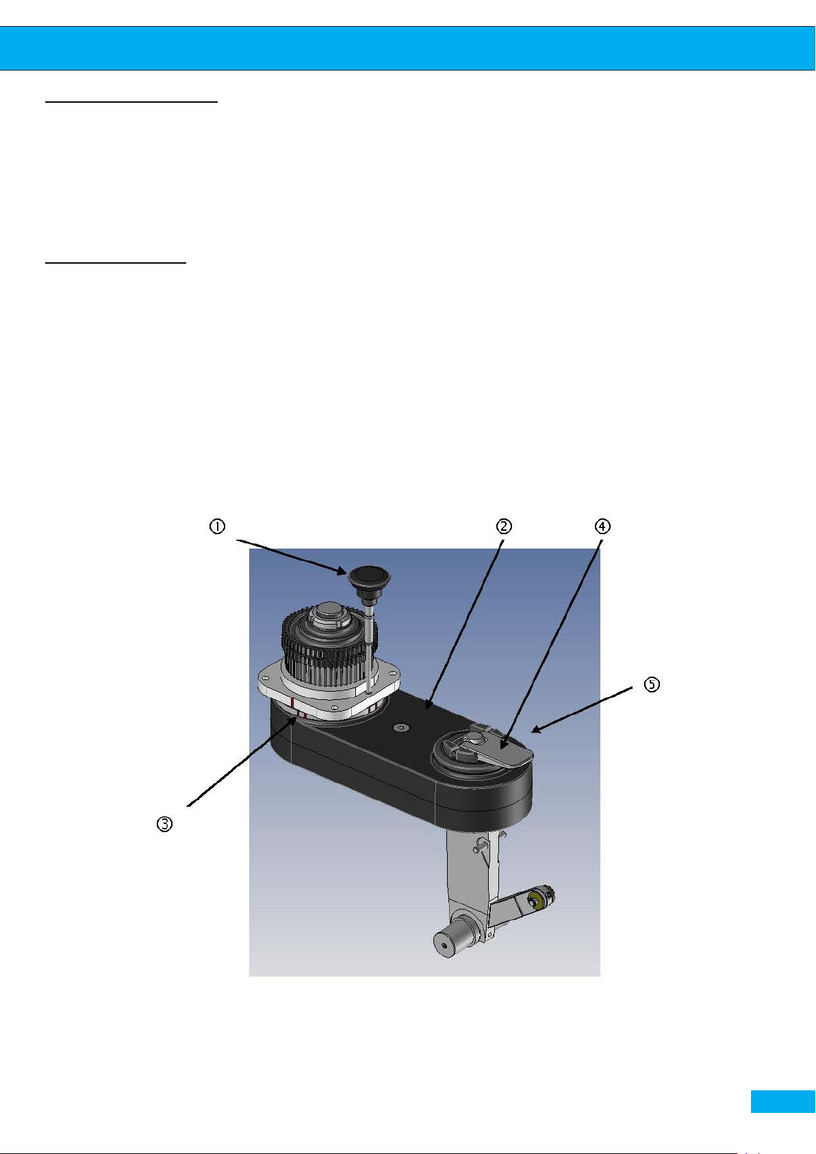
Small arms rotation
1. Lift the xing pin -1-
2. Rotate the small arm -2- until the desired reference mark -3-.
3. Insert the xing pin -1- again.
4. Repeat the operation on all four arms.
Use on the track
1. Put the small arms into the Position C.
2. Lift the front right and rear left pins 1.
3. Loosen the levers (4) of the four wheel axis.
4. Lock the steering column.
5. Before moving the dolly on the ground, insert the pins 1, lock four levers (4) and
release the steering column. Now the dolly is ready to work on the ground.
pag. 17
Page 18
User Guide
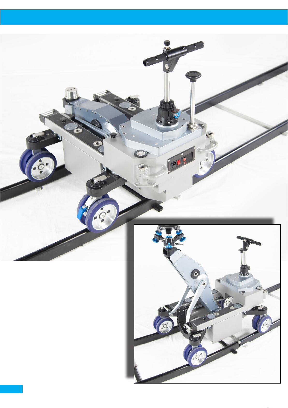
Work on the 620mm track transversely
pag. 18
620mm track. Dolly mounted with the longitudinal axis
Page 19
User Guide
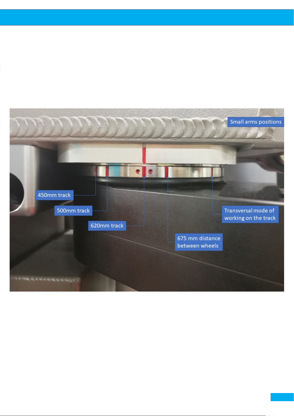
Alignment of the ring nut in the 5 available positions. From left to right, 450mm track, 500mm track, 620mm standard track, 675mm
distance between the wheels, and the final position with the small arms perpendicular to the longitudinal axis of the dolly (transversal
placement of the dolly on 620mm track)
pag. 19
Page 20
User Guide
Hydraulic system
Hydraulic system allows the Dolly to perform up to six lifts. The charging
time is approximately 60 seconds. The proportional control valve allows the
arm to have a speed range from 0 to 2 seconds.
Charging of the dolly can be made in two ways:
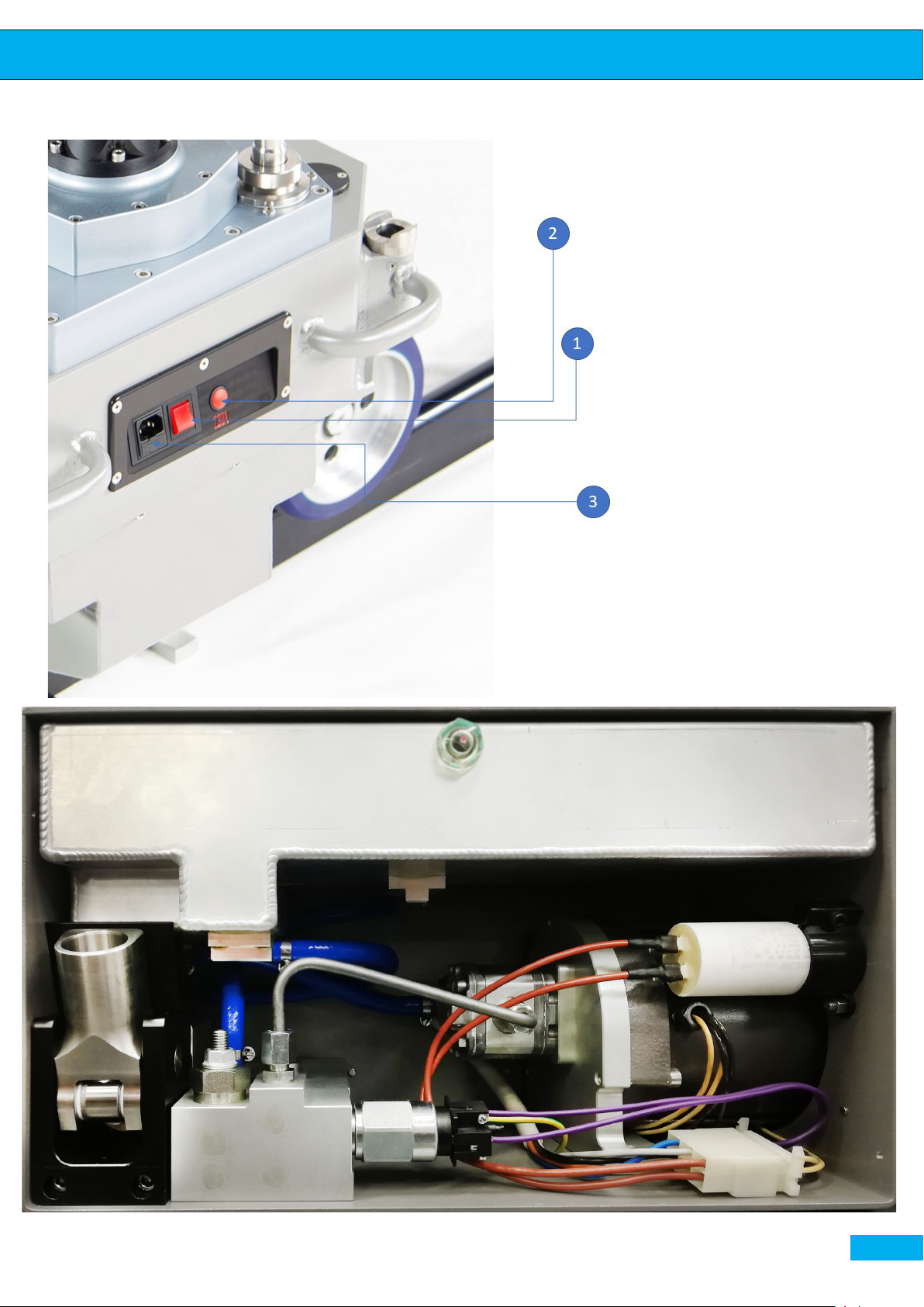
• Electrical (depending on the preset voltage): Connect the power cable
supplied, switch on the main switch (1) and press the charging buon (2).
Charging will stop automatically once you reach the maximum pressure
of 180 Bar set by the manufacturer to avoid the damage to the Dolly. In
case of anomalous currents or voltages the electrical box is equipped with
a fuse (3) that protects the system, easily replaceable;
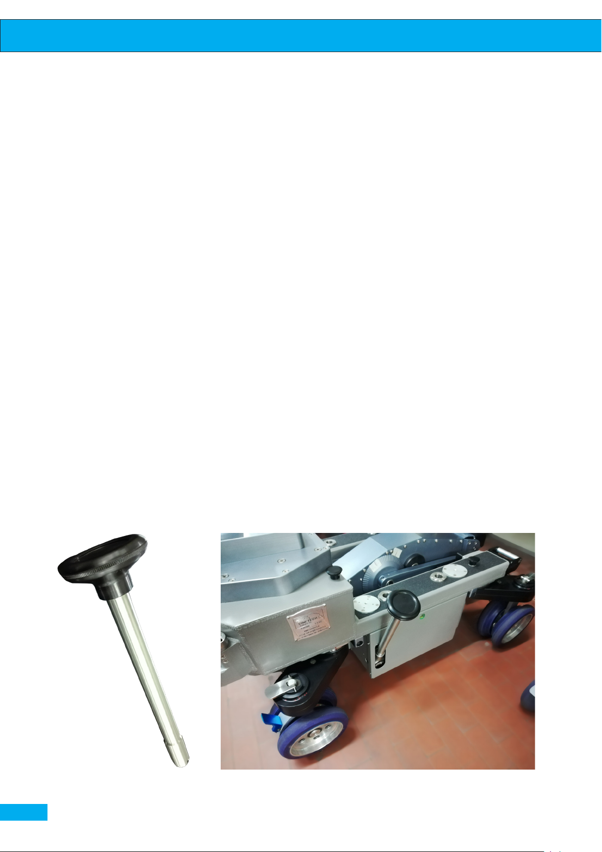
• The second way of charging is through a manual pump that is used only
in places where there is no electricity (as shown in image A). Insert the
control rod (g. B) into the special housing and pump it up and down
until it reaches the desired pressure.
pag. 20
Fig. B manual pump-rod
fig.A - manual charge pump handle (configuration)
Page 21
User Guide
Albatross Dolly electric plate
Box Albatross control unit, internal components of the hydraulic system
pag. 21
Page 22
User Guide
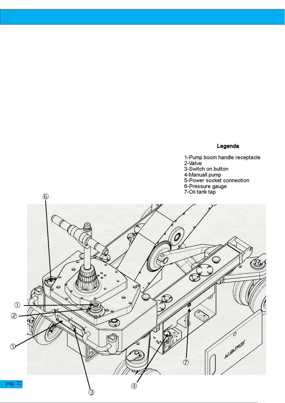
To start working with the dolly you need to do the following operations:
• Charge the dolly
• Insert the operating rod into the valve receptical -2-
• Turn the rod counterclockwise to raise the arm and clockwise to lower it.
• Each 180 bar charge allows 6/7 rises.
Now the dolly is ready to work
pag. 22
Page 23

User Guide
pag. 23
Page 24
User Guide
pag. 24
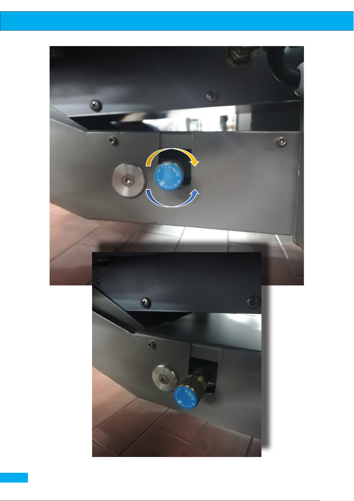
Detailed view of the flow regulator. Counterclockwise rotation for opening and clockwise for decreasing
flow
Page 25
User Guide
Oil ow regulator
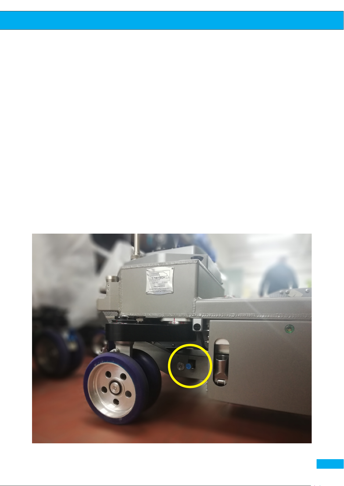
The Albatross dolly is equipped with the oil ow regulator that is located
on the right side under the small arm. It allows to change the speed of the
lifting-arm movement.
When the regulator is completely open, the ow in the hydraulic system is at
maximum speed and the lifting-arm can go up in 1.5 sec.
By modifying the ow, with the gradual closure of the regulator, arm can
reach the slower speeds while going up.
The going down of the arm, as in all known dollies, depends only on the
gravity force. As a result the speed will vary per second depending on the
weight you put on the head.
Position of the flow regulator in the structure under the right small arm
pag. 25
Page 26
User Guide
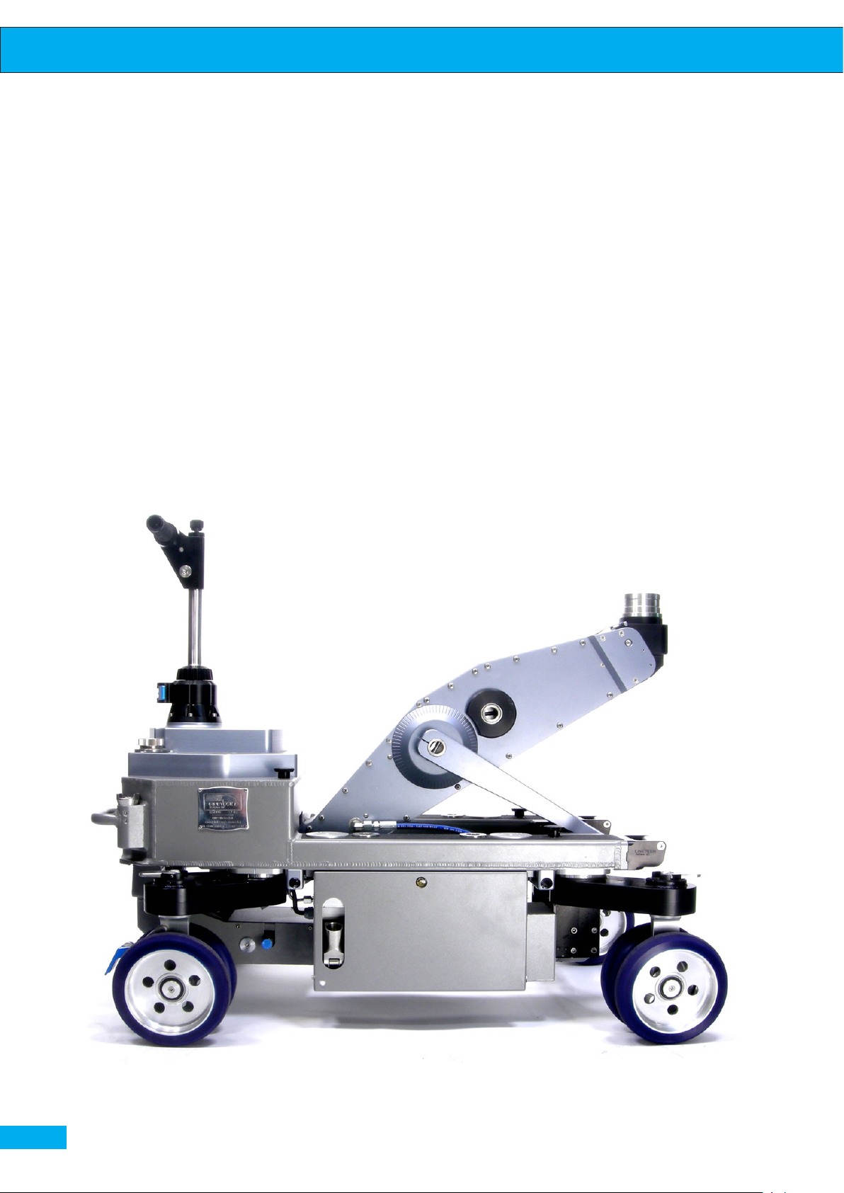
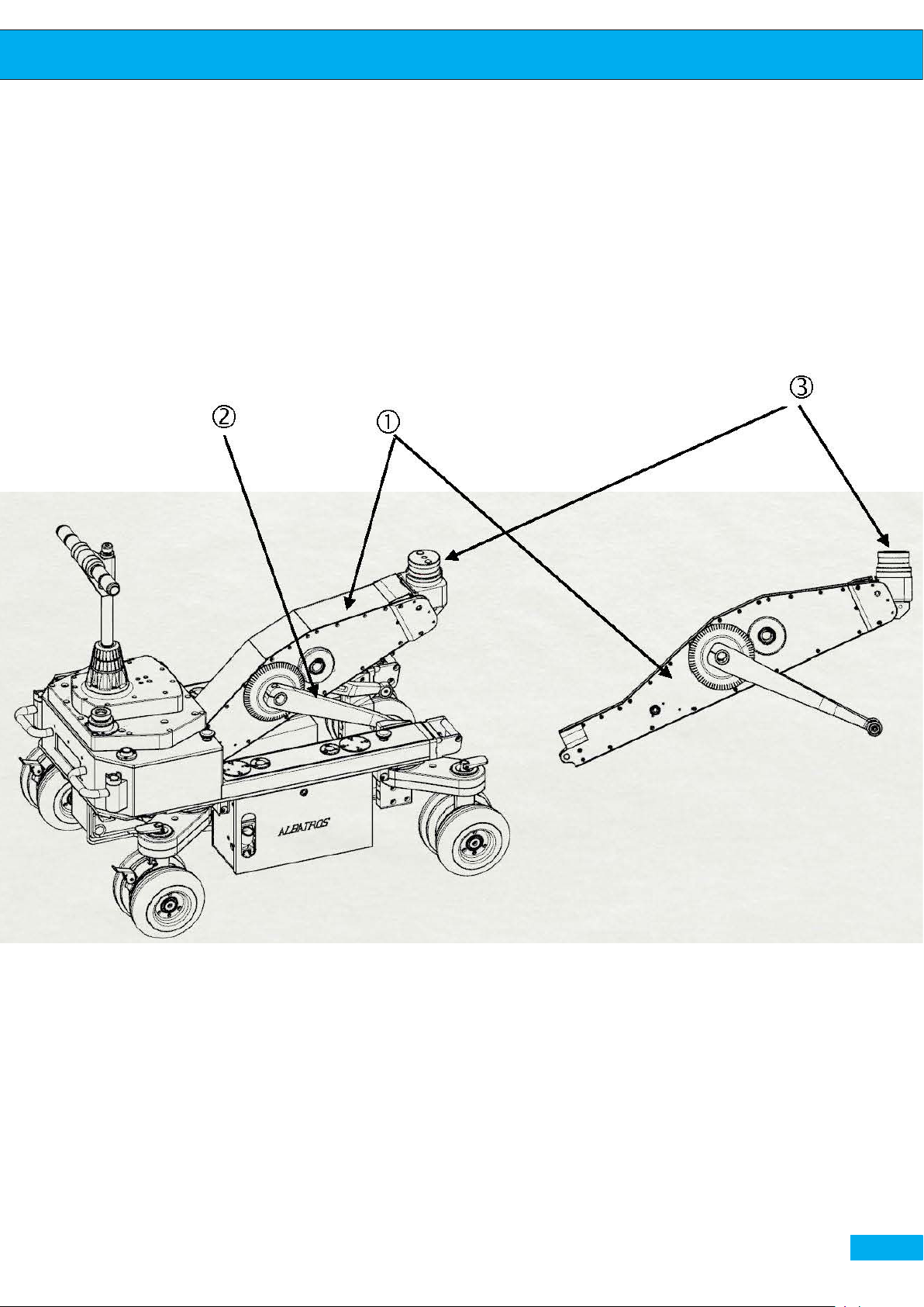
Lifting arm
The Albatros arm is characterized by incredible stability, uidity, absence of
noise and absolute perpendicularity of its movement. It is very sturdy and
can lift up to 60 Kg on the head reaching a maximum height of about 1.16
meters from the ground. One can x mitchell or euromount aachment on
the top of the arm.
pag. 26
Page 27
User Guide
pag. 27
Page 28
User Guide
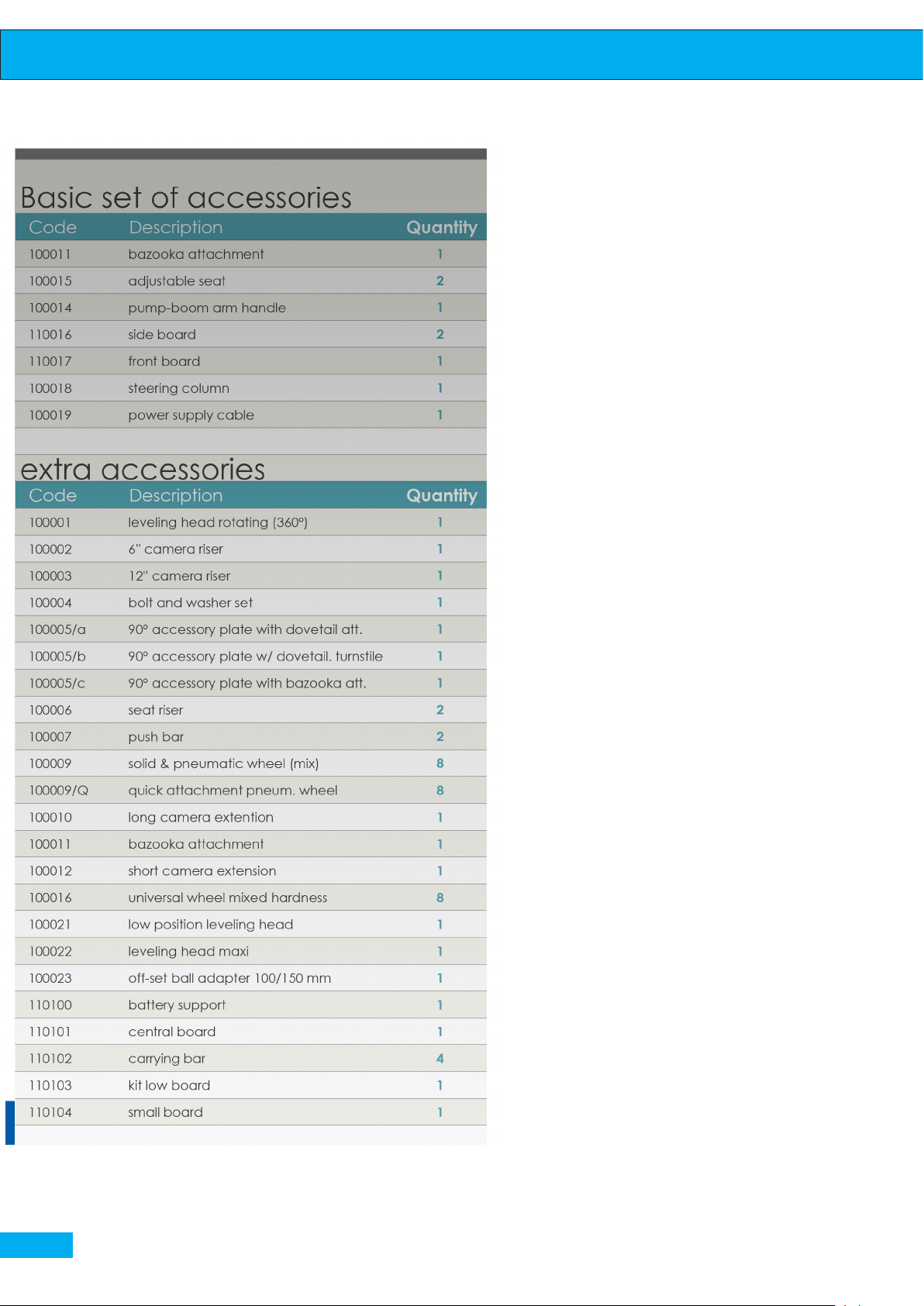
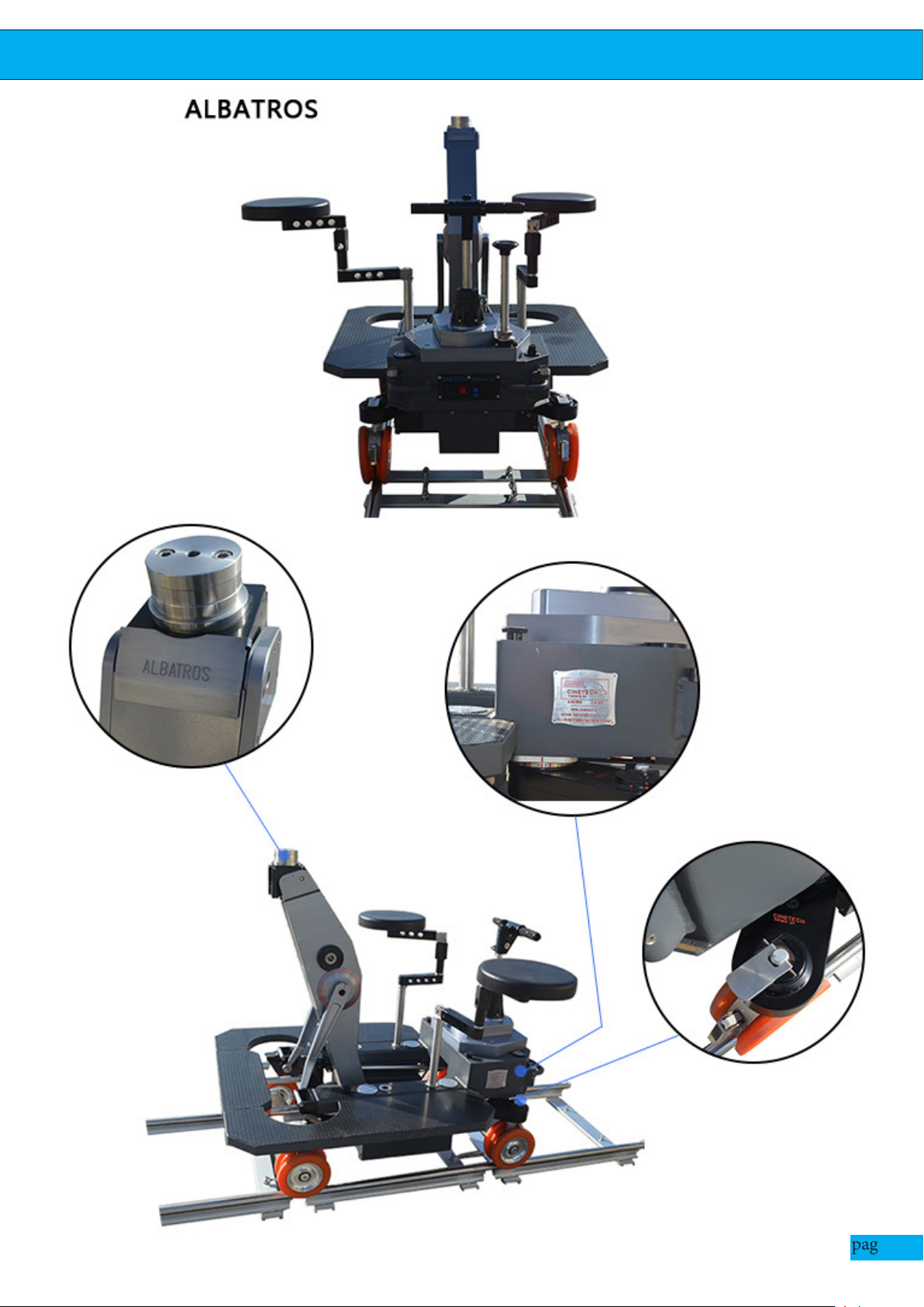
ACCESSORIES
SEATS: designed to make the ope-
rator’s job easier;
BAZOOKA ATTACHMENT (euromount): universal for all types of
euromount heads, with an easy extraction;
PUMP-BOOM ARM HANDLE: Used to operate the dolly bo-
om-arm and also as a manual pump
to recharge the pressure of the dolly
where there is no electricity;
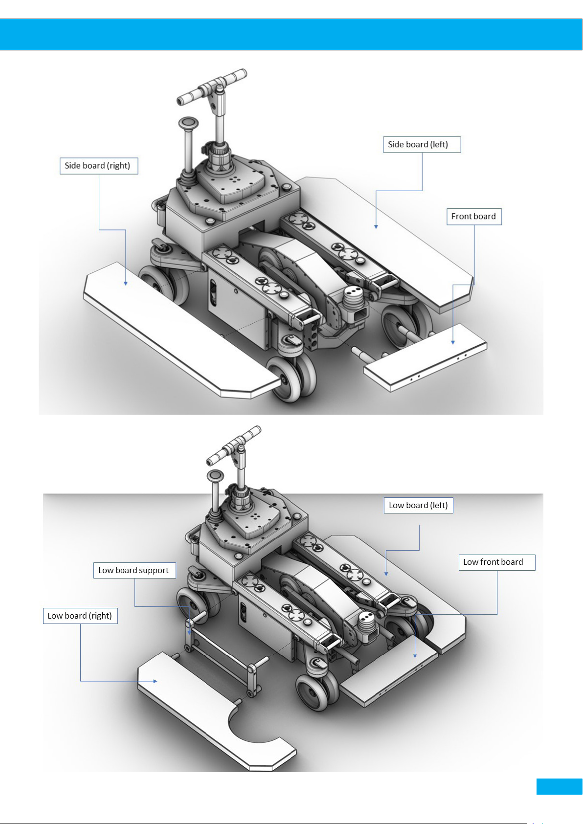
SET OF BOARDS: provides com-
plete walk-around possibility on
the dolly in the high setup;
6 “RISER: raises the camera up to
the height of 6”;
12 “RISER: raises the camera up to
the height of 12”;
90 ° ACCESSORY PLATE - TURNSTILE OR FIXED: allows to make
the low shots;
SEAT EXTENSION: accessory that
allows to raise the seat;
PUSH BAR: must be used while
pushing the dolly on the track;
pag. 28
CENTRAL BOARD: placed cen-
trally so one can have a major ver-
Page 29
User Guide
pag. 29
Page 30
User Guide
satility in movement;
BI-COMPONENT WHEELS that have
the inner rim with 90 shore hardness for
beer gyration on tracks and the outer
rim with 70 shore hardness for improved
steering and traction on any surface.
LONG/ SHORT CAMERA EXTENSION
allow to o-set the camera respect to the
head.
KIT LOW BOARD allows the operator to
go on the lower level respect to the stan-
dard boards level. The front board can be
reversed so it stays on the same level with
the low board.
LOW POSITION LEVELING HEAD
equipped with two adjustable pins and
one xed pin, can be mounted on the head
to get the perfect leveling of the camera.
The leveled camera will be o-set respect
to the head.
LEVELING HEAD MAXI equipped with
three adjustable pins, can be xed on the
head to get the perfect leveling of the camera, remains on the same level of the
head.
OFF-SET BALL ADAPTER 150 MM Al-
lows to o-set the camera respect to the
axis of the lifting-arm.
pag. 30
Page 31
User Guide
pag. 31
Page 32
User Guide
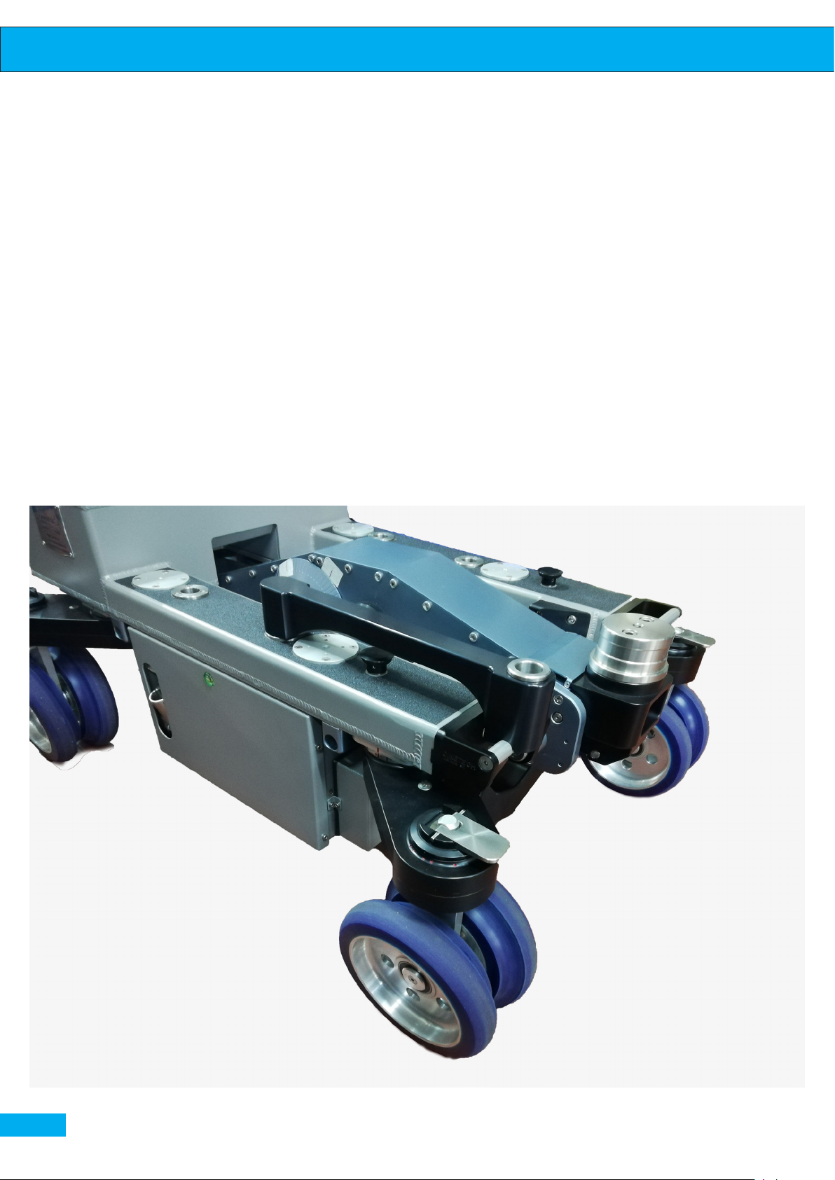
Front seat support:
New accessory which allows to x the seat at the front part of the dolly, thus having a possibility to seat closer to the camera.
Accessory installation
pag. 32
Page 33
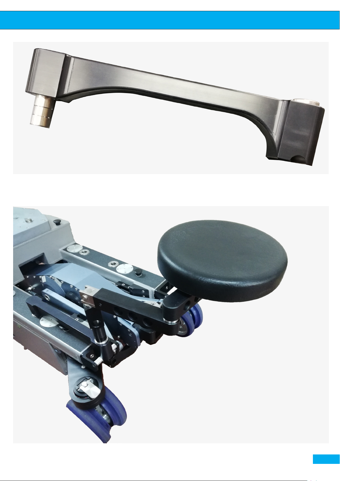
Front seat support
User Guide
Seat fixing on the top of front seat support
pag. 33
Page 34
 Loading...