

Page 1
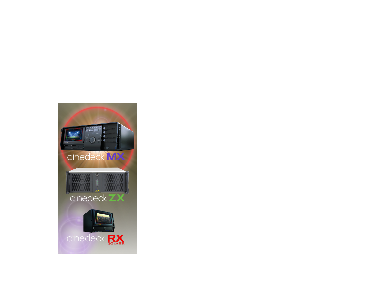
Cinedeck
20, 40, 45
RX3G - ZX
USER GUIDE - Cinedeck Version 4.5 13126
- MX
Page 2
Contacting Cinedeck
Support:
General
Information:
For non-support
general inquiries,
please contact us at:
You can also call:
+1 888-390-4460
Some international
locations do not allow
dialing a US toll free
number, in that case call:
+1 646-642-6985
Additionally, the
Cinedeck website
has a significant
array of resources
including brochures,
where to buy,
video tutorials
and technical
documents.
Technical Support office hours are 9am-6pm US Eastern Time, but we generally respond
to support requests from 8am to midnight, 7 days a week, and at odd hours of the night.
Response time is generally within minutes during business hours.
To initiate a support request, it is preferred that you fill out the support form on the
Cinedeck website: http://cinedeck.com/support/
The direct support email address is: [email protected]
Phone support can be reached at +1 888-390-4460 (option 2). If you do not reach
us, please do leave a message, indicate your version number and as much relevant
informations as possible and use the above noted support form as we do endeavor to
respond ASAP within the expanded hours noted above.
Some international locations do not allow dialing a US toll free number, in that case call: +1 646-642-6985
Please Note! It is generally essential and helpful to have as much information
as possible about the nature of the problem and the setup involved, including; Cinedeck
model, Cinedeck software version {Prefs page}, the relevant log files {C:\cinedeck\logs},
Cinedeck settings such as codec, wrapper, storage in use and all related equipment being
used; source/camera settings, audio embedders, timecode source, etc.
If you are using an esoteric piece of equipment in the signal chain, it is critical that we
know so we can make a correct diagnosis.
Is it plugged in? Often the simplest things can make life difficult... Always
check the basics! Are power, cabling and signal paths all confirmed to be good?
Page - 2 of 297
Page 3

Table of Contents - Cinedeck User Guide
Contacting Cinedeck ............................................ 2
Table of Contents - Cinedeck User Guide
........................ 3
1.0 Introduction ................................................ 27
1.1 About This Manual .............................................. 27
1.2 Copyright and Trademarks ....................................... 28
1.3 Safety Information .............................................. 28
1.4 FCC and CE Information ......................................... 29
1.5 Cinedeck Product Overview ....................................... 30
2.0 What’s in the Box ........................................... 33
2.1 Cinedeck RX3G ................................................ 33
2.2 Cinedeck MX .................................................. 34
2.3 Cinedeck ZX .................................................. 35
2.4 Features ..................................................... 36
2.4.1 Hardware ................................................ 36
2.4.2 Software ................................................ 36
Table of Contents
2.4.3 - ...................................................... 36
3.0 Installation ................................................. 37
3.1 Important ..................................................... 37
3.2 Connecting your deck ........................................... 38
3.2.1 Audio connections ......................................... 39
3.2.2 AES - BNC to XLR .......................................... 40
3.2.3 - ...................................................... 40
Table of Contents - 3 of 297Cinedeck USER GUIDE - Cinedeck Version 4.5 13126 – June 15, 2015 - 19:21
Page 4

3.3 Recording destinations .......................................... 41
3.3.1 SSDs ................................................... 42
3.3.2 USB & eSATA ............................................. 43
3.3.3 Network Storage ........................................... 45
3.3.4 DAS Storage .............................................. 46
3.3.5 - ...................................................... 46
3.4 RX3G front panel ............................................... 47
1- Headphone ..................................... 48
2- eSATA port ..................................... 48
3- USB port ....................................... 48
4- Power button .................................... 48
5- future use ...................................... 48
6- Drive tray ...................................... 48
7- Drive lock & ejector ................................ 48
8- LCD Display .................................... 48
Table of Contents
3.5 RX3G back panel ............................................... 49
9- AUX 1/2 out ..................................... 50
10- DC power ..................................... 50
11- eSATA ports .................................... 50
12- USB3 ports .................................... 50
13- HDMI for GUI ................................... 50
14- RS-232 ports ................................... 50
15- RS-422 ports ................................... 50
16- Monitor Out .................................... 50
17- DVI for GUI .................................... 50
18- VGA for GUI .................................... 50
19- AES In & Out ................................... 50
20- Timecode option ................................. 51
Table of Contents - 4 of 297Cinedeck USER GUIDE - Cinedeck Version 4.5 13126 – June 15, 2015 - 19:21
Page 5

21- RS-422 out ..................................... 51
22- Gb lan / USB2 ports ............................... 51
23- Analog in ...................................... 51
24- LTC in/loop .................................... 51
25- Reference In .................................... 51
26- Video Out ..................................... 51
27- Video In ....................................... 51
3.6 MX front panel ................................................. 52
28- LCD control panel ................................ 53
29- LCD display .................................... 53
30- Card readers ................................... 53
31- eSATA port .................................... 53
32- USB3 ports .................................... 53
33- Control panel ................................... 53
34- Headphone .................................... 53
Table of Contents
35- Drive lock and ejector ............................. 53
36- Drive tray ..................................... 53
37- Power button ................................... 53
3.6.1 MX control panel ........................................... 54
38- jog shuttle knob ................................. 55
39- select | open ................................... 55
40- set in ........................................ 55
41- prev clip ...................................... 55
42- frame +1 | load clip ............................... 55
43- reverse play .................................... 55
44- record ........................................ 55
45- rewind ....................................... 55
46- shift ......................................... 55
Table of Contents - 5 of 297Cinedeck USER GUIDE - Cinedeck Version 4.5 13126 – June 15, 2015 - 19:21
Page 6

47- led indicators ................................... 55
48- ch 1 | on air .................................... 56
49- ch 2 | lock UI ................................... 56
50- ch 3 ......................................... 56
51- ch 4 ......................................... 56
52- full/mini | full scrn ................................ 56
53- loop | ping pong ................................. 56
54- back ......................................... 56
55- pause ........................................ 56
56- forward fast .................................... 57
57- play ......................................... 57
58- frame +1 | load pl ................................ 57
59- next clip ...................................... 57
60- set out ....................................... 57
3.6.2 - ...................................................... 58
Table of Contents
3.7 MX Back panel ................................................. 59
61- Video in 3&4 .................................... 60
62- Video out 3&4 ................................... 60
63- Super out 3&4 .................................. 60
64- Aux out 3/4 .................................... 60
65- Reference in 3 & 4 ................................ 60
66- Video I/O 1 & 2 .................................. 60
67- RS-422 ports ................................... 60
68- Monitor out .................................... 60
69- Redundant power ................................ 60
70- Power supply alarm ignore .......................... 60
71- Master timecode in & out ........................... 61
72- USB2 ports .................................... 61
Table of Contents - 6 of 297Cinedeck USER GUIDE - Cinedeck Version 4.5 13126 – June 15, 2015 - 19:21
Page 7

73- Gb Ethernet .................................... 61
74- USB3 ports .................................... 61
75- AES in & out 1-16 ................................ 61
76- Analog line in ................................... 61
77- Optional network ................................. 61
78- AES in & out 17-32 ................................ 61
79- LTC 1 & 2 in/loop ................................. 61
80- LTC 3 & 4 in/loop ................................. 62
81- DVI/HDMI for GUI ................................. 62
82- eSATA ports .................................... 62
3.8 ZX Front panel ................................................. 63
83- Power and drive access door ......................... 64
84- Door lock ..................................... 64
85- Drive trays ..................................... 64
86- Power button ................................... 64
Table of Contents
87- USB port ...................................... 64
3.9 ZX Back panel ................................................. 65
88- Video in 3&4 .................................... 66
89- Video out 3&4 ................................... 66
90- Aux out 3/4 .................................... 66
91- LTC 3&4 in/loop ................................. 66
92- Video in 1&2 .................................... 66
93- Video out 1&2 ................................... 66
94- Aux out 1/2 .................................... 66
95- LTC 1&2 in/loop ................................. 66
96- Reference in 1&2 ................................. 66
97- Reference in 3&4 ................................. 66
98- monitor out .................................... 66
Table of Contents - 7 of 297Cinedeck USER GUIDE - Cinedeck Version 4.5 13126 – June 15, 2015 - 19:21
Page 8

99- RS-422 ports ................................... 66
100- Master timecode in & out ........................... 67
101- Redundant power ............................... 67
102- Power supply alarm ignore ......................... 67
103- AES in & out 1-16 ................................ 67
104- USB2 ports .................................... 67
105- Gb ethernet ................................... 67
106- USB3 ports .................................... 67
107- Analog line in .................................. 67
108- DVI/HDMI for GUI ................................ 67
109- optional network ................................ 68
110- eSATA ports ................................... 68
3.10 Inserting & ejecting drives ....................................... 69
4.0 Accessories ................................................ 71
4.1 Drive docks ................................................... 71
Table of Contents
4.2 Rack mount kits ................................................ 72
4.3 Control panels ................................................. 73
5.0 User Interface .............................................. 74
5.1 UI Introduction ................................................. 74
5.2 UI explained .................................................. 75
5.3 Keyboard shortcuts ............................................. 77
5.4 Powering on .................................................. 82
5.5 Desktop details ................................................ 83
5.5.1 On-screen keyboard ........................................ 83
5.5.2 Touchscreen setup ......................................... 84
5.5.3 HotSwap! ................................................ 84
Table of Contents - 8 of 297Cinedeck USER GUIDE - Cinedeck Version 4.5 13126 – June 15, 2015 - 19:21
Page 9

5.5.4 - ...................................................... 84
5.6 Settings - exporting / importing .................................... 85
5.7 Multi view screen description ..................................... 87
5.8 Multi view screen ............................................... 88
111- Single view toggle ............................... 89
112- remote indicator ................................ 89
113- sync indicator .................................. 89
114- master space/time ............................... 89
115- signal indicator ................................. 89
116- proxy space/time ................................ 89
117- timecode ..................................... 89
118- timecode source ................................ 89
119- redundant master space/time ........................ 90
120- start & elapsed time .............................. 90
121- redundant proxy space/time ......................... 90
Table of Contents
122- record button .................................. 90
123- gang button ................................... 90
124- RS-422 button .................................. 90
125- SDI char button ................................. 90
126- UI overlays & LUT button .......................... 91
127- setup button ................................... 91
128- stop button ................................... 91
129- encode overview ................................ 91
130- play button .................................... 91
131- error log button ................................. 91
132- audio meters .................................. 91
133- background (bg) button ........................... 91
134- P button ...................................... 92
Table of Contents - 9 of 297Cinedeck USER GUIDE - Cinedeck Version 4.5 13126 – June 15, 2015 - 19:21
Page 10

135- M button ..................................... 92
5.9 Single channel view ............................................. 93
136- multi view toggle ................................ 94
137- lock ........................................ 94
138- tcp remote .................................... 94
139- elapsed time ................................... 94
140- start ........................................ 94
141- le TC source .................................. 94
142- timecode ..................................... 94
143- end ......................................... 94
144- record mode ................................... 94
145- 422 mode ..................................... 94
146- record ....................................... 94
147- gang ........................................ 95
148- LUT ........................................ 95
Table of Contents
149- char out ...................................... 95
150- overlays ..................................... 95
151- analysis ...................................... 95
152- 100% ........................................ 95
153- full screen .................................... 95
154- setup ....................................... 95
155- stop ........................................ 96
156- encode overview ................................ 96
157- play ........................................ 96
158- error log ..................................... 96
159- audio meters .................................. 96
160- bg ......................................... 96
161- P .......................................... 97
Table of Contents - 10 of 297Cinedeck USER GUIDE - Cinedeck Version 4.5 13126 – June 15, 2015 - 19:21
Page 11

162- M .......................................... 97
163- remote ...................................... 97
164- sync ........................................ 97
165- signal ....................................... 97
5.10 Headphone Monitor Controls ..................................... 98
5.11 Record Modes ................................................ 99
5.11.1 Normal ................................................. 99
5.11.2 Pause .................................................. 99
5.11.3 Pause & Seek in File ...................................... 101
5.11.4 Insert Baseband ......................................... 103
5.11.5 Insert Baseband Master .................................... 105
166- device control ................................. 106
167- record mode .................................. 106
168- RS-422 mode ................................. 106
169- edit point display ............................... 106
Table of Contents
170- edit point controls .............................. 106
171- edit mode .................................... 106
172- preview ee/pb ................................. 106
173- preview edit .................................. 107
174- edit start tc ................................... 107
175- le tc display ................................. 107
176- create blank tape ............................... 107
177- trim le ..................................... 107
178- target le info ................................. 107
179- open le to edit ................................ 107
180- audio src .................................... 107
181- disable remote track arm .......................... 107
182- set up source>le mapping ........................ 107
Table of Contents - 11 of 297Cinedeck USER GUIDE - Cinedeck Version 4.5 13126 – June 15, 2015 - 19:21
Page 12

183- le audio overview .............................. 107
5.11.6 Insert Audio Matrix ....................................... 108
5.11.7 - ..................................................... 108
5.12 Create Black File ............................................. 109
5.13 Character Out Customization .................................... 110
5.14 Overlay Customization ......................................... 111
5.15 Video Analysis Tools .......................................... 112
5.16 Setup tabs explained .......................................... 113
5.17 Overview tab ................................................ 114
184- channel toggle ................................ 115
185- page tabs .................................... 115
186- current project ................................ 115
187- current scene ................................. 115
188- current sub-scene .............................. 115
189- tape/reel ID ................................... 115
Table of Contents
190- input settings ................................. 116
191- master encoder settings .......................... 116
192- master le destinations ........................... 116
193- proxy encoder settings ........................... 116
194- proxy le destinations ........................... 116
195- name ...................................... 116
196- label ....................................... 116
197- preview ..................................... 116
198- preview LUT .................................. 116
199- burn LUT .................................... 116
200- copy to other channels ........................... 116
201- save and close ................................ 11 7
202- segment mode ................................ 117
Table of Contents - 12 of 297Cinedeck USER GUIDE - Cinedeck Version 4.5 13126 – June 15, 2015 - 19:21
Page 13

203- drop & loss stop ............................... 117
5.18 Project manager ............................................. 118
204- page tabs .................................... 119
205- project list ................................... 119
206- manage projects button .......................... 119
207- project metadata button .......................... 119
208- name ...................................... 119
209- label ....................................... 119
210- project <> channel assignment ...................... 120
211- cancel button ................................. 120
212- save & close button ............................. 120
213- apply button .................................. 120
214- project list scroll ............................... 120
5.18.1 Path & le names explained ................................. 121
5.18.2 Path & le name templates .................................. 123
Table of Contents
215- page tabs .................................... 124
216- current project display ........................... 124
217- start take# ................................... 124
218- start roll# .................................... 124
219- channel assignments ............................ 125
220- cancel button ................................. 125
221- save & close button ............................. 125
222- edit user wildcards.............................. 125
223- show wildcards ................................ 125
224- reset to defaults ............................... 125
225- tape/reel id ................................... 126
226- le name .................................... 126
227- redundant path ................................ 126
Table of Contents - 13 of 297Cinedeck USER GUIDE - Cinedeck Version 4.5 13126 – June 15, 2015 - 19:21
Page 14

228- primary path .................................. 126
229- global wildcards ............................... 126
230- all encoders use same templates .................... 126
231- master ...................................... 126
232- proxy ...................................... 126
5.18.3 Path editor ............................................. 127
233- current project ................................ 128
234- template .................................... 128
235- expansion ................................... 128
236- wildcard shortcuts .............................. 128
237- on screen keyboard ............................. 128
238- cancel button ................................. 128
239- save & close button ............................. 128
5.18.4 File name editor ......................................... 129
240- current project ................................ 130
Table of Contents
241- template .................................... 130
242- expansion ................................... 130
243- wildcard shortcuts .............................. 130
244- on screen keyboard ............................. 130
245- cancel button ................................. 130
246- save & close button ............................. 130
5.18.5 Edit user & global wildcards ................................. 131
247- title ........................................ 132
248- expansion ................................... 132
249- variable ..................................... 132
250- on screen keyboard ............................. 132
251- cancel button ................................. 132
252- save & close button ............................. 132
Table of Contents - 14 of 297Cinedeck USER GUIDE - Cinedeck Version 4.5 13126 – June 15, 2015 - 19:21
Page 15

5.18.6 Scenes list ............................................. 133
253- page tabs .................................... 134
254- current project display ........................... 134
255- scenes list ................................... 134
256- manage scenes button ........................... 134
257- scene metadata ................................ 134
258- channel assignments ............................ 135
259- cancel button ................................. 135
260- save & close button ............................. 135
261- scene list scroll ................................ 135
5.18.7 Sub-scenes & User Lists ................................... 136
5.18.8 - .................................................... 136
5.19 Input tab ................................................... 137
262- page tabs .................................... 138
263- res-resolution ................................. 138
Table of Contents
264- fps-frame rate ................................. 138
265- format ...................................... 138
266- transport .................................... 138
267- source ...................................... 138
268- audio ...................................... 138
269- preview ..................................... 139
270- signal loss behavior ............................. 139
271- frame drop behavior ............................. 140
272- channel toggle ................................ 140
273- sync ....................................... 140
274- save and close ................................ 140
275- copy settings from .............................. 141
276- copy to other channels ........................... 141
Table of Contents - 15 of 297Cinedeck USER GUIDE - Cinedeck Version 4.5 13126 – June 15, 2015 - 19:21
Page 16

277- audio delay .................................. 142
278- sync ....................................... 142
279- signal ...................................... 142
280- auto detect ................................... 142
5.19.1 Audio delay ............................................ 143
5.19.2 - .................................................... 143
5.20 Master tab .................................................. 144
281- page tabs .................................... 146
282- codec ...................................... 146
283- quality ...................................... 146
284- wrapper ..................................... 147
285- audio ...................................... 147
286- timecode .................................... 148
287- segment .................................... 148
288- write ....................................... 149
Table of Contents
289- primary ..................................... 149
290- secondary ................................... 149
291- channel toggle ................................ 149
292- video burn ................................... 149
293- closed captions ................................ 149
294- vbr enable ................................... 150
295- endian type .................................. 150
296- encoder enable ................................ 150
297- use mxf clip folders ............................. 150
298- encoder name ................................. 150
299- use record TC offset ............................. 150
300- record mode .................................. 150
301- copy to other channels ........................... 151
Table of Contents - 16 of 297Cinedeck USER GUIDE - Cinedeck Version 4.5 13126 – June 15, 2015 - 19:21
Page 17

302- save and close ................................ 151
303- generate xml .................................. 151
5.21 Proxy tab ................................................... 152
304- page tabs .................................... 153
305- codec ...................................... 153
306- quality ...................................... 153
307- wrapper ..................................... 154
308- audio ...................................... 154
309- timecode .................................... 154
310- segment .................................... 154
311- write ....................................... 155
312- primary ..................................... 155
313- secondary ................................... 155
314- channel toggle ................................ 155
315- video burn ................................... 155
Table of Contents
316- lut ........................................ 156
317- save and close ................................ 156
318- copy to other channels ........................... 156
319- generate xml .................................. 157
320- use record tc offset ............................. 157
321- encoder name ................................. 157
322- vbr enable ................................... 157
323- endian type .................................. 158
324- use mxf clip folders ............................. 158
325- encoder enable ................................ 158
5.22 Audio routing ................................................ 159
326- source and encode display ........................ 160
327- input meters .................................. 160
Table of Contents - 17 of 297Cinedeck USER GUIDE - Cinedeck Version 4.5 13126 – June 15, 2015 - 19:21
Page 18

328- source to destination selector ...................... 160
329- delay ....................................... 160
330- presets ..................................... 160
331- copy settings ................................. 161
332- undo all ..................................... 161
333- save/back ................................... 161
334- additional channels toggle ......................... 162
335- channel toggle ................................ 162
336- switch to .................................... 162
5.23 Video Burn Settings ........................................... 163
337- input id tab ................................... 164
338- video burn ................................... 164
339- position ..................................... 164
340- safe % ...................................... 164
341- size ....................................... 164
Table of Contents
342- text ........................................ 164
343- block ...................................... 165
344- encoder burn timecode source ...................... 165
345- user text .................................... 165
346- properties panel area ............................ 165
347- cancel ...................................... 165
348- save and close ................................ 165
5.24 TC & Automation tab .......................................... 166
349- page tabs .................................... 167
350- record control ................................. 167
351- external device via SDI ........................... 167
352- EDL ....................................... 168
353- input rec-run TC ............................... 168
Table of Contents - 18 of 297Cinedeck USER GUIDE - Cinedeck Version 4.5 13126 – June 15, 2015 - 19:21
Page 19

354- preroll ...................................... 169
355- master clock mode.............................. 169
356- gen tc mode .................................. 169
357- gen tc source ................................. 170
358- Special timecode modes .......................... 171
359- channel toggle ................................ 171
360- tc offsets .................................... 172
361- df / ndf ..................................... 172
362- save and close ................................ 172
5.24.1 TC offsets .............................................. 173
5.24.2 EDL editor ............................................. 174
363- edl name .................................... 175
364- le name .................................... 175
365- proxy name .................................. 175
366- in tc ....................................... 175
Table of Contents
367- out tc ...................................... 175
368- duration ..................................... 175
369- keypad ..................................... 175
370- df | ndf ..................................... 175
371- cancel | enter ................................. 175
372- undo | cancel \ save and close ...................... 176
373- le ........................................ 176
374- delete current ................................. 176
375- insert before .................................. 176
376- insert after ................................... 177
377- append ..................................... 177
378- events list scroll ............................... 177
379- out tc ...................................... 177
Table of Contents - 19 of 297Cinedeck USER GUIDE - Cinedeck Version 4.5 13126 – June 15, 2015 - 19:21
Page 20

380- in tc ....................................... 177
381- edl events ................................... 177
5.24.3 Sample EDL ............................................ 178
5.24.4 - .................................................... 178
5.25 Prefs tab ................................................... 179
382- page tabs .................................... 180
383- recording .................................... 180
384- remote control ................................ 181
385- 444 output ................................... 181
386- prefs ....................................... 182
387- ui mode ..................................... 182
388- application ................................... 182
389- misc ....................................... 183
390- licenses ..................................... 183
391- channel toggle ................................ 183
Table of Contents
392- system ..................................... 184
393- use old drive mapping ........................... 184
394- save and close ................................ 184
395- ip address ................................... 184
396- support info .................................. 184
5.25.1 UI mode ............................................... 185
5.25.2 - .................................................... 185
5.26 4K / UHD mode .............................................. 186
5.27 V1 Signal Generator tab ........................................ 190
6.0 Recording ................................................. 192
6.1 Recording, multi view .......................................... 193
397- single view toggle .............................. 194
Table of Contents - 20 of 297Cinedeck USER GUIDE - Cinedeck Version 4.5 13126 – June 15, 2015 - 19:21
Page 21

398- master & proxy - space / time ....................... 194
399- start & elapsed time ............................. 194
400- record button ................................. 194
401- gang button .................................. 195
402- frame buffer indicator ............................ 195
403- encode overview ............................... 195
404- stop button .................................. 195
6.2 Recording, single channel view ................................... 196
405- multi view toggle ............................... 197
406- lock ....................................... 197
407- elapsed ..................................... 197
408- start ....................................... 197
409- end ........................................ 197
410- record button ................................. 198
411- gang button .................................. 198
Table of Contents
412- frame buffer indicator ............................ 199
413- encode overview ............................... 199
414- stop button .................................. 199
6.3 - ........................................................... 200
7.0 Playback .................................................. 201
7.1 Playback, multi view ........................................... 202
415- multi view toggle ............................... 203
416- start | end ................................... 203
417- elapsed time .................................. 203
418- in | out ...................................... 203
419- touch transport ................................ 203
420- le ........................................ 203
Table of Contents - 21 of 297Cinedeck USER GUIDE - Cinedeck Version 4.5 13126 – June 15, 2015 - 19:21
Page 22

421- play head .................................... 203
422- le info ..................................... 203
423- open ....................................... 203
424- transport controls .............................. 204
425- back ....................................... 204
7.1.1 Playback, touch transport ................................... 205
7.1.2 - ..................................................... 206
7.2 Playback, single channel view .................................... 207
426- multi view toggle ............................... 208
427- dur ........................................ 208
428- start ....................................... 208
429- elapsed time .................................. 208
430- end ........................................ 208
431- rem ........................................ 208
432- le ........................................ 208
Table of Contents
433- play head .................................... 208
434- open clip .................................... 208
435- transport controls .............................. 209
436- edit points ................................... 210
437- back ....................................... 210
438- le info ..................................... 210
439- p not psf .................................... 210
7.3 Clip manager ................................................. 211
440- page tabs .................................... 212
441- disk list ..................................... 212
442- folder ...................................... 212
443- folder ...................................... 212
444- clip list ..................................... 212
Table of Contents - 22 of 297Cinedeck USER GUIDE - Cinedeck Version 4.5 13126 – June 15, 2015 - 19:21
Page 23

445- sort controls .................................. 212
446- scroll columns ................................ 212
447- play selected ................................. 213
448- play all in folder ................................ 213
449- nd media ................................... 213
450- manage disk .................................. 214
451- manage folder ................................. 215
452- manage clips ................................. 216
453- select all .................................... 216
454- select none .................................. 216
455- add to playlist ................................. 217
456- back ....................................... 217
457- list view toggle ................................ 217
7.4 Playlist manager .............................................. 218
458- page tabs .................................... 219
Table of Contents
459- disk list ..................................... 219
460- folders ..................................... 219
461- playlists list .................................. 219
462- sort controls .................................. 219
463- select buttons ................................. 219
464- play selected ................................. 219
465- play all in folder ................................ 219
466- edit selected playlist ............................ 219
467- manage playlists ............................... 220
468- list view toggle ................................ 220
469- export ...................................... 220
470- back ....................................... 220
7.4.1 Playlist editor ............................................ 221
Table of Contents - 23 of 297Cinedeck USER GUIDE - Cinedeck Version 4.5 13126 – June 15, 2015 - 19:21
Page 24

471- editor view ................................... 222
472- preview ..................................... 222
473- clip - position timecode ........................... 222
474- clip name .................................... 222
475- clip thumbnail ................................. 222
476- clip timecode ................................. 222
477- clip thumbnail scroll ............................. 222
478- playlist timecode ............................... 222
479- manage assets ................................ 223
480- playlist settings ................................ 223
481- edit selected clip ............................... 223
482- duplicate selected .............................. 223
483- move selected ................................. 223
484- timecode display ............................... 224
485- export ...................................... 224
Table of Contents
486- cancel ...................................... 224
487- save and close ................................ 224
488- output 23.98 as 59i .............................. 224
489- playlist settings overview ......................... 224
7.4.2 Playlist settings .......................................... 225
490- playlist timecode type ............................ 226
491- playlist timecode settings ......................... 226
492- frame rate ................................... 226
493- p/psf ....................................... 226
494- cancel ...................................... 226
495- save and close ................................ 226
7.5 - ........................................................... 227
7.5.1 - ..................................................... 227
Table of Contents - 24 of 297Cinedeck USER GUIDE - Cinedeck Version 4.5 13126 – June 15, 2015 - 19:21
Page 25

8.0 Remote control ............................................ 228
8.1 Device Manager ............................................... 229
8.2 RS-422 - COM port setup ........................................ 230
8.3 RS-422 Cables & pin-outs ....................................... 233
8.4 Avid Digital Cut ............................................... 234
8.4.1 Cinedeck settings ......................................... 234
8.4.2 Media Composer settings ................................... 235
8.4.3 AMP protocol ............................................ 236
8.4.4 Using VNC applications ..................................... 237
8.4.5 - ..................................................... 238
9.0 Service & Trouble ......................................... 239
9.1 Best practices ................................................ 239
9.2 Touchscreen calibration ........................................ 241
9.3 Important drive information ...................................... 242
9.4 Installing SSDs ............................................... 243
Table of Contents
9.5 Initializing new drives .......................................... 244
9.6 Reinitializing SSDs ............................................ 249
9.7 Formating drives .............................................. 252
9.8 Disk caching settings .......................................... 253
9.9 Changing drive letters .......................................... 255
9.10 Error Checking .............................................. 257
9.11 Secure erase ................................................ 259
9.12 Updates .................................................... 262
9.13 Create a restore point ......................................... 262
9.14 Cinedeck Update installation .................................... 266
9.15 Using a Restore Point ......................................... 270
9.16 Bluesh update .............................................. 273
Table of Contents - 25 of 297Cinedeck USER GUIDE - Cinedeck Version 4.5 13126 – June 15, 2015 - 19:21
Page 26

9.17 Restore factory image ......................................... 275
9.18 Update a USB restore key ...................................... 276
9.19 Create USB restore key ........................................ 277
9.20 Create system image .......................................... 281
10.0 FAQ & Features .......................................... 282
10.1 FAQ > Features .............................................. 282
10.2 - .......................................................... 297
11.0 Specications ............................................ 298
11.1 Basic specications ........................................... 298
11.2 Codecs & wrappers ........................................... 305
11.3 Data rates .................................................. 332
11.4 Storage calculator ............................................ 343
12.0 Index .................................................... 344
Table of Contents
Table of Contents - 26 of 297Cinedeck USER GUIDE - Cinedeck Version 4.5 13126 – June 15, 2015 - 19:21
Page 27
1.0 Introduction
1.1 About This Manual
Note: This manual primarily reflects the state of Cinedeck hardware and software as of the date and
version number noted on the cover and in the page footers however, because of the many customer
specific customizations and minor updates, some sections will vary slightly from your system and the
stated version. This manual will be updated as new features are implemented and will not necessarily
reflect legacy information.
What’s in the manual:
This user manual describes the functions available in the Cinedeck software, as well as relevant information
regarding upgrades, hardware information such as pin definitions for connectors, interaction with 3rd party
software such as NLEs, and further technical information of interest to users.
For a good initial understanding, there are several overview sections which should be reviewed:
“1.5 Cinedeck Product Overview” on page 30
“3.0 Installation” on page 37
“5.1 UI Introduction” on page 74
How to use this manual:
The manual is divided into multiple sections. The first two chapters after the table of contents (which, in PDF
form, employs hyperlinks) are an introduction and overview of what comes with each machine.
The following chapters, which include physical descriptions for each deck and user interface details, make
extensive use of captions for each control and connection. Captions include a caption ID and page numbers,
directing the reader to descriptions and operational explanations. When viewed as a PDF, the captions employ
hyperlinks to provide direct navigation to the relevant details. Additionally, Pressing “ALT+Left Arrow” or “ALT+Right Arrow” will navigate backwards and forwards through previously viewed pages. Towards the end of
the manual are several sections with specifications, appendices of useful information and a section describing
each feature and frequently asked questions.
Page - 27 of 297Cinedeck USER GUIDE - Cinedeck Version 4.5 13126 – June 15, 2015 - 19:21
About This Manual Introduction
Page 28
1.2 Copyright and Trademarks
All trademarks are the property of their respective owners.
Cinedeck is a trademark of Cine Design Group LLC
ProRes is a trademark of Apple Computer Corporation
Avid Media Composer is a trademark of Avid Technology, Inc.
DNxHD is a trademark of Avid Technology, Inc.
Windows is a trademark of Microsoft Corporation
Premiere is a trademark of Adobe Corporation
All other tradenames referenced are service marks, trademarks, or registered trademarks of their respective
companies.
1.3 Safety Information
WARNING: Take care of your Cinedeck as you would cameras and other sensitive
electronic equipment. Take care especially to keep water and moisture away from the unit.
Getting your Cinedeck wet will void the warranty and COULD CAUSE ELECTRIC SHOCK!
WARNING: Your Cinedeck needs ventilation for safe operation. DO NOT block the front
or rear of the unit as this will restrict airflow, causing it to overheat, potentially damaging the unit
and voiding the warranty.
Page - 28 of 297Cinedeck USER GUIDE - Cinedeck Version 4.5 13126 – June 15, 2015 - 19:21
Copyright and Trademarks Introduction
Page 29
1.4 FCC and CE Information
Caution: The Federal Communications Commission warns the user that changes or modifications to
the unit not expressly approved by the party responsible for compliance could void the user’s authority to
operate the equipment.
FCC Class B Statement: This equipment has been tested and found to comply with limits for
Class B digital device pursuant to Part 15 of Federal Communications Commission (FCC) rules.
CC and CE Compliance Statement: This equipment has been tested and found to
comply with the limits of the European Council Directive on the approximation of the law of the member
states related to electromagnetic compatibility (89/336/EEC) according to EN 55022 Class B.
These limits are designed to provide reasonable protection against frequency interference in residential
installation. This equipment generates, uses and can radiate radio frequency energy, and if not installed
or used in accordance with the instructions, may cause harmful interference to radio communication.
However, there is no guarantee that interference will not occur in television reception, which can
be determined by turning the equipment off and on. The user is encouraged to try and correct the
interference by one or more of the following measures:
• Reorient or relocate the receiving antenna
• Increase the separation between the equipment and the receiver
• Connect the equipment into an outlet on a circuit different from that to which receiver is connected
FCC and CE Information Introduction
Page - 29 of 297Cinedeck USER GUIDE - Cinedeck Version 4.5 13126 – June 15, 2015 - 19:21
Page 30

1.5 Cinedeck Product Overview
In the most basic sense, Cinedecks are video production ingest and playout appliances. They can initially
be described as tape deck replacements in that you can drop one in place of a tape deck, use the existing
connections and put it to work but your Cinedeck’s features and functions go far beyond what traditional tape
decks have ever offered.
Multi-channel ingest and playback using the storage destinations, native codecs and file types which best fit
your workflow remain the core benefits of Cinedeck recorders however simplicity is key in todays’ demanding
production environments. Cinedecks Plug & Play nature, supported by an intuitive, easy to navigate user
interface with a full array of analysis tools, allows you to quickly setup and manage your sessions. This is
enhanced by the project orientation of your Cinedeck. Leveraging the Cinedeck project based design allows
you to have, as needed, full channel flexibility allowing completely separate settings between channels or
uniform and simultaneous changes across multiple channels.
CODECS
First and foremost, Cinedecks provide native support for a broad selection of codecs and file wrappers and the
list is continuously being adding to.
Of course where appropriate you can optionally select from multiple file wrappers such as; true native Avid OPAtom MXF, MOV, MXF OP-1A and others.
Coming in a later release, Cinedeck plans to enhance the product line with RAW recording.
Additionally, Cinedecks handle 422 or 444 color sampling and bit depths of 8bit and 10bit to render your
content as accurately as possible.
STORAGE
In many modes, Cinedecks offer the ability to write both master and proxy files for each input and when it
comes to writing your files, no other product comes close to Cinedecks flexibility of recording; internally, to
local attached drives and to network storage.
For internal recording, Cinedeck relies on standard 2.5” SSDs mounted in ‘dual drive’ removable and hot
swappable carriers or sleds. You have the option of utilizing one or more internal drives as needed for your
Cinedeck Product Overview Introduction
Page - 30 of 297Cinedeck USER GUIDE - Cinedeck Version 4.5 13126 – June 15, 2015 - 19:21
Page 31

Cinedeck Product Overview / cont...
particular production and the available desktop and installable docks with SATA connectivity give you instant
high-speed access to your content. Of course additional drive carriers or sleds are available and installing drives
in the sleds is simply a matter of a few screws.
Before going further with the many other storage options it is important to understand Cinedecks redundant
record capability. Cinedecks offer the ability to connect and record to multiple destinations. See “3.3 Recording
destinations” on page 41.
For many inputs, Cinedeck can not only write a Master and a Proxy, the file writes can be redundant meaning
two of each file can be written wherever you need them. And by redundant we don’t mean a copy, we mean
two concurrent and totally separate file writes of each file.
By leveraging this redundant capability you can, for example, have a safe copy in the machine and a network
copy, instantly available for editing or a customer take away copy as soon as “Stop” is pressed. The options are
virtually limitless.
SSD drives are recommended for internal recording however, each Cinedeck also has a multitude of USB and
SATA connections, allowing the use of direct attached storage so for example recordings can be made to USB3
drives as well as external eSATA devices such as RAID arrays.
Direct to network recording is one of the most important Cinedeck features.
Cinedecks run on Windows7 embedded. One of the advantages to being on a Windows platform is Cinedeck
can leverage the internal networking capability and where appropriate, 3rd party support for Windows so if you
have a SAN system which provides a Windows client, that client can likely run on the Cinedeck, allowing direct
to SAN recording with all of the advantages of being a true SAN client.
Whether it is Avid ISIS, Harmonic MediaGrid, Facilis Terablock or another network storage solution, the
advantages and efficiencies realized for multi-cam and other edit hungry productions by providing instant
access to new content, can be easily measured in real and significant cost savings.
Especially when recording to local attached and network destinations, it is important to understand bitrate,
multi-write capability and bandwidth and to thoroughly test your environment before deploying your workflow
Page - 31 of 297Cinedeck USER GUIDE - Cinedeck Version 4.5 13126 – June 15, 2015 - 19:21
Cinedeck Product Overview Introduction
Page 32
Cinedeck Product Overview / cont...
on a production.
In general, when recording to an appropriate destination across a LAN dedicated for video, standard gigabit
is fine for the normal compressed formats such as ProRes or DNxHD. Conversely, it goes without saying that
you will never achieve the maximum theoretical throughput to any destination or device and recording an
uncompressed HD stream across a standard gigabit network will not be successful, however there are many
more subtle variables when selecting an external destination such as pipe size, network traffic, multiuser and
multi-read/write capability, etc.
Cinedecks provide dual 1Gb LAN connections which can be “teamed” if your network supports that. Some
Cinedeck models also have an available PCIe slot for installing a 10Gb Ethernet card, 8 or 16Gb Fiber Channel
card or direct attached storage adapter, to support high bitrate sessions.
Thorough testing cannot be emphasized enough.
Cinedeck Product Overview Introduction
Page - 32 of 297Cinedeck USER GUIDE - Cinedeck Version 4.5 13126 – June 15, 2015 - 19:21
Page 33

2.0 What’s in the Box
2.1 Cinedeck RX3G
Cinedeck RX3G is the solution for productions where space and weight are at a premium. Taking its
cue from fully loaded MX, the rugged, milled-aluminum case is built to
withstand environments that are on-the-move like OB vans or flight packs.
Weighing around 12lbs (5.5kg) and measuring 4RU at half-rack width,
RX3G brings tons of functionality in a small footprint.
Built-in to the front panel are;
• User interface touch display which can be tilted
• A eSATA and USB port
• Two removable drive trays, each of which can hold two SATA drives
• A headphone jack
Internally, RX3G provides two full duplex 3G channels, a full selection of master formats, accompanied by
an H.264 proxy and most of the available Cinedeck features.
In HD and SD mode, RX3G can record master and proxy for each channel.
With the 4K mode option, RX3G can play a single channel of 4K.
RX3G comes with;
• Two AC to DC power supplies with localized power cables
• A touch screen stylus
• One USB software installation disk (Restore disk)
• If you purchased accessories such as media drives or a rack kit with your Cinedeck, they will be
included in a separate box
Please check to ensure that all expected contents are included. In the event something is missing, please
immediately contact your reseller or Cinedeck Support: See “Contacting Cinedeck” on page 2
Cinedeck RX3G What’s in the Box
Page - 33 of 297Cinedeck USER GUIDE - Cinedeck Version 4.5 13126 – June 15, 2015 - 19:21
Page 34
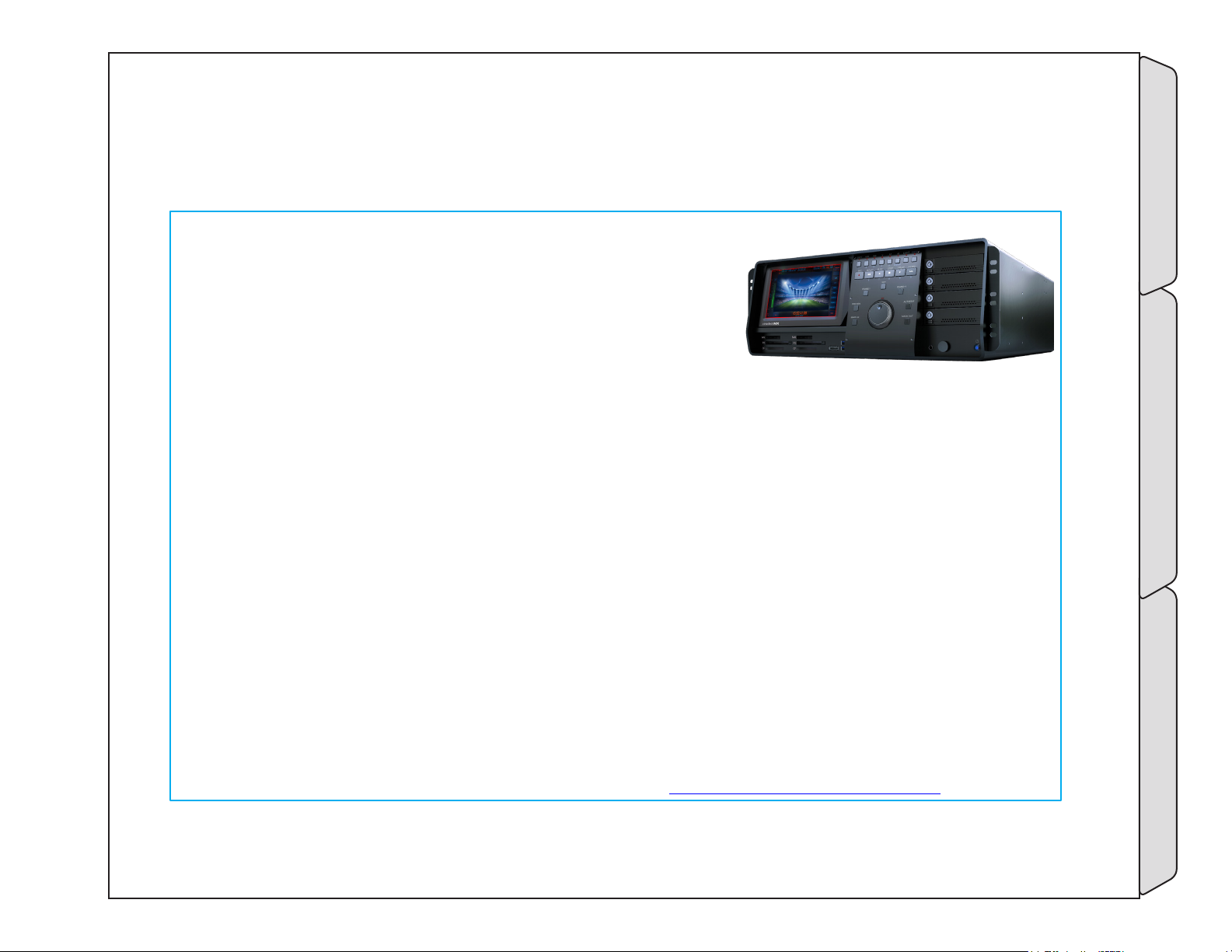
2.2 Cinedeck MX
MX is the flagship four-channel recorder. Built in to the front panel are;
• User interface touch display which can be tilted
• Solid state memory card readers for P2, SxS and compact flash
• A eSATA and USB ports
• A tactile jog/shuttle control
• Touch panel controls
• Four removable drive trays, each of which can hold two SATA
drives
• Dual mini and ¼” headphone jacks
• Dual headphone volume controls
Internally, MX provides four full duplex 3G channels with the full selection of master and proxy formats,
high-bandwidth network capabilities and most of the available Cinedeck features.
In HD and SD mode, MX records master and proxy for each channel.
With the 4K mode option, MX simultaneously records 4K files, HD master files, HD proxy files and h.264
streamable files, with or without LUT applied.
MX comes with;
• Localized power cables
• A touch screen stylus
• One USB software installation disk (Restore disk)
• If you purchased accessories such as media drives or a rack kit with your Cinedeck, they will be
included in a separate box.
Cinedeck MX What’s in the Box
Please check to ensure that all expected contents are included. In the event something is missing, please
immediately contact your reseller or Cinedeck Support: See “Contacting Cinedeck” on page 2
Page - 34 of 297Cinedeck USER GUIDE - Cinedeck Version 4.5 13126 – June 15, 2015 - 19:21
Page 35
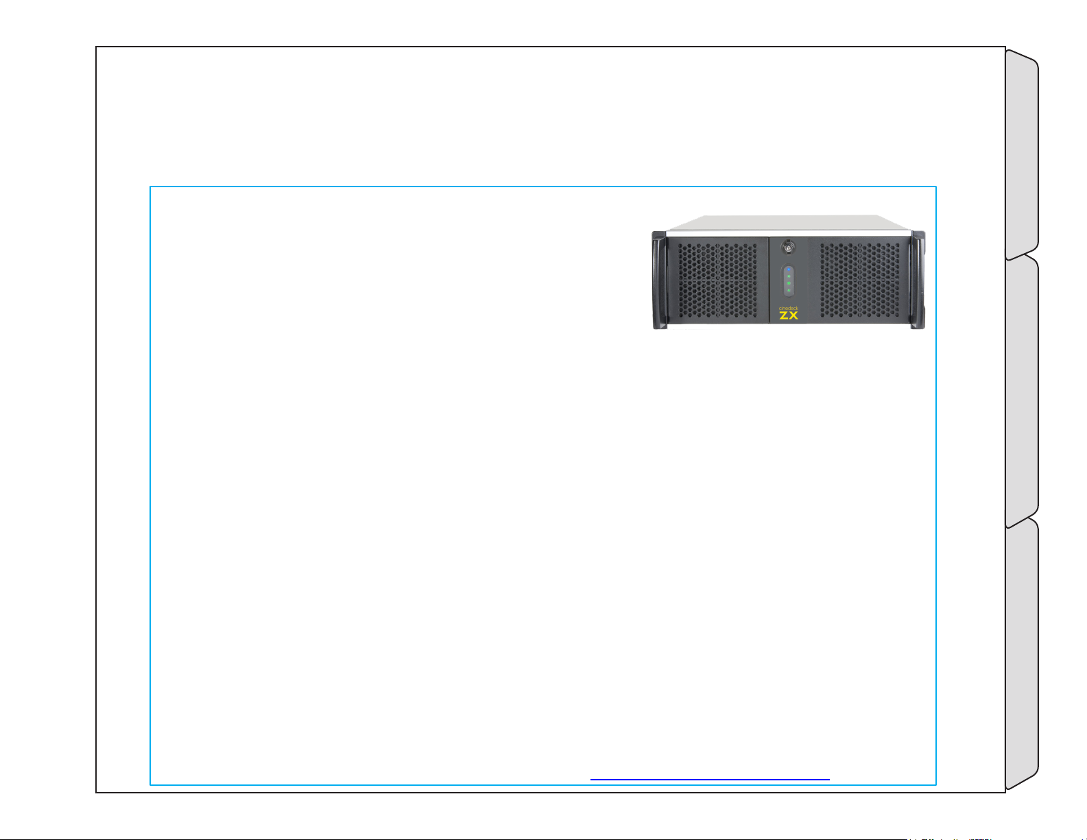
2.3 Cinedeck ZX
ZX is a modular design based on MX. Primarily for rack-mount installations, Cinedeck ZX lets you
choose from a broad selection of software toolsets and hardware
configurations, to build a cost effective system that meets your
specific ingest, playback and transcoding needs. As a result, not all
ZX systems have the same features but you always have the ability
to add extra capabilities if your workflow changes.
Built-behind the front panel are;
• Two USB ports
• Four removable drive trays, each of which can hold two SATA drives
ZX is available in three base models:
• ZX20 is a two channel system
• ZX40 is a four channel system which, when fully loaded, most closely matches MX
• ZX45 is a four channel system, which in terms of pure processing power, is a step above MX
Internally, ZX provides two or four full duplex 3G channels, with an optional selection of master and proxy
formats and high-bandwidth network capabilities.
In HD and SD mode ZX records master and proxy for each channel.
With the appropriate options, ZX records 4K files up to 60p, along with HD master files, HD proxy files and
h.264 streamable files, with or without LUT applied.
ZX comes with;
• Localized power cables
• One USB software installation disk (Restore disk)
• If you purchased accessories such as media drives or a rack kit with your Cinedeck, they will be
included in a separate box
Please check to ensure that all expected contents are included. In the event something is missing, please
immediately contact your reseller or Cinedeck Support: See “Contacting Cinedeck” on page 2
Cinedeck ZX What’s in the Box
Page - 35 of 297Cinedeck USER GUIDE - Cinedeck Version 4.5 13126 – June 15, 2015 - 19:21
Page 36

2.4 Features
2.4.1 Hardware
The overall design and build of each Cinedeck model is oriented towards professional video production and
while the current Cinedeck generation comes in different forms with some hardware differences, at their heart
they are all very similar. Much of the hardware is “off-the shelf” which allows Cinedeck designers to quickly
respond as improved technology comes available. Starting at the basics, there are many options available for
video input and output processing but the quality of the actual image which comes through today’s cards
differers significantly. The current Cinedeck generation are all based on Bluefish video I/O processing cards
which were selected for their clean video I/O, access to the complete signal path and their responsive and active
interest in supplying a quality product.
There are also some custom hardware elements; not so visible electronic components such as the RS-422 board
and very visible parts like the tilt displays, control panels and the stainless steel back panels.
2.4.2 Software
The user interface is what really makes a Cinedeck unique. The interface has been in development since 2010
and most users agree that it is very effective and easy to navigate, making what can be quite a complicated
process, quick and easy.
It is also important to note that the Cinedeck application is running on top of a Windows 7 embedded
installation. The discussion will go on forever as to the plus and minus points of Windows but for the purposes
of a versatile system such as a Cinedeck, there are significant advantages in terms of storage flexibility and the
capability to be integrated into larger system environments.
For a complete overview of the many features available in your Cinedeck, please refer to: “10.0 FAQ & Features”
on page 282
Cinedeck hope your experience with our decks is positive and appreciate any comments you may have so
please feel free to contact us. See “Contacting Cinedeck” on page 2
Page - 36 of 297Cinedeck USER GUIDE - Cinedeck Version 4.5 13126 – June 15, 2015 - 19:21
HardwareFeatures What’s in the Box
Page 37
3.0 Installation
3.1 Important
Storage: Cinedecks are primarily SOLID STATE recorders; recording should always be to Solid State
Drives (SSDs) mounted in the internal removable drive bays. Currently Cinedeck support the Samsung
840pro, 850pro and EVO SSD drives. USB and eSATA are available for media offload but due to the vast
number of variables involved in different mechanical hard drives and external enclosures, Cinedeck do not
recommend recording to these external drives.
Network connectivity may be used for recording, but performance will vary depending on network
topology, network storage device performance, network and server traffic, etc. It is critical that an IT
professional be involved in the configuration and support of any network infrastructure.
Performance claims are based upon recording to internal SSD media.
It is very strongly recommended that any workflow be thoroughly
tested before use in a mission-critical production environment.
While “spinning drives” and network recording may be used, Cinedeck does not in any way guarantee that
performance of such recording media (including SANs, external RAID arrays, etc.), will be adequate to take
advantage of the features of a Cinedeck.
It is up to the end user to understand the risks and to have the technical expertise on hand to properly
take advantage of recording media other than the internal SSDs.
Page - 37 of 297Cinedeck USER GUIDE - Cinedeck Version 4.5 13126 – June 15, 2015 - 19:21
-Important Installation
Page 38

3.2 Connecting your deck
In many respects, the initial setup of a Cinedeck is no different than a traditional tape deck and also, like a tape
deck, some care needs to be taken during the installation process.
Cinedecks are not terribly heavy but the physical location is still very important.
Install the Cinedeck in a protected and stable environment, such as in a rack, on a table, etc., where the deck
can not fall or be otherwise susceptible to undesirable environmental or hazardous conditions. As with any
electronic equipment, it is important that the area have sufficient ventilation and be a reasonable temperature.
Use common sense; if you are not comfortable because of the temperature or humidity, the environment is
likely not appropriate for your equipment either so special care should be taken.
Assure there is a stable and clean power source. Because Cinedeck recorders use auto switching redundant
power, it is preferred to have power coming from two independent sources. The use of a UPS (uninterruptible
power supply) is also highly recommended to help prevent data loss.
Cinedecks use standard professional video and IT interconnects.
Make any appropriate video, audio, reference, network and control connections, assuring that the cables
are in good operational condition. This is of particular importance as digital signals are very susceptible to
intermittent data loss caused by cable issues which can greatly complicate troubleshooting.
Refer to the rest of this chapter to learn about the various external parts of your Cinedeck.
-Connecting your deck Installation
Page - 38 of 297Cinedeck USER GUIDE - Cinedeck Version 4.5 13126 – June 15, 2015 - 19:21
Page 39

3.2.1 Audio connections
Your Cinedeck can utilize several different audio sources.
Most common is recording “embedded“ audio which is coming into the deck on a SDI BNC connection. In this
situation the system can accept up to 16 audio channels with each video.
AES is also commonly utilized and each channel pair can accept up to 8 AES channels, also on BNC connections.
It is also possible to use analog audio.
Analog can be connected via the motherboard rear mounted unbalanced mini jack. See the appropriate rear
panel description for your deck and “268- audio” on page 138 in the user interface input menu setup section.
There are also a number of ways to connect balanced audio sources.
The best and often lowest cost solution is to use an analog to digital AES adapter. There are many on the
market but one example is the AJA ADA4 4-Channel A/D & D/A Converter. In all cases, these small converter
boxes provide a simple and fairly foolproof direct connection for analog audio sources.
Another excellent but more expensive option would be an analog to SDI embedder.
These small converter boxes accept analog audio and SDI video sources and
merge the audio into the video ancillary data track. They are also simple and fairly
foolproof and there are also many of these on the market.
Lastly, a XLR or TRS balanced audio pair
can be introduced to the system using a
Focusrite 2i2 USB audio adapter.
Keep in mind that, especially when your audio is traveling via a different
path from the video, audio<>video timing issues can arise. This can generally be
managed internally via Cinedeck’s the audio delay. See “5.19.1 Audio delay” on page 143
For additional information on any of these solutions, contact Cinedeck support.
See “Contacting Cinedeck” on page 2
Audio connectionsConnecting your deck Installation
Page - 39 of 297Cinedeck USER GUIDE - Cinedeck Version 4.5 13126 – June 15, 2015 - 19:21
Page 40
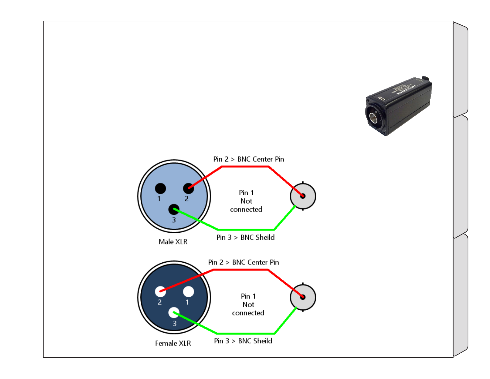
3.2.2 AES - BNC to XLR
Cinedecks utilize BNC coaxial connections for AES in and out while some of your other equipment may use XLR
connectors. It is very simple to make up basic interconnect or adapter cables to go from XLR to BNC.
Coaxial cable should be used in place of twisted pair for these cables - The theory is that, although
unbalanced, the high density coaxial shield acts as a Faraday cage, protecting the signals. The
pin connections are shown below.
Especially for longer distances, balanced connections are recommended. You may
consider using XLR to BNC (110 ohm>75 ohm) impedance matching transformer /
adapters, similar to the Neutrik NADITBNC, NADITBNC-MX and Canare BCJ-XJ-TRB or
other more specialized transmitter/receiver modules.
AES - BNC to XLRConnecting your deck Installation
Page - 40 of 297Cinedeck USER GUIDE - Cinedeck Version 4.5 13126 – June 15, 2015 - 19:21
Page 41
3.3 Recording destinations
All Cinedecks can write video and audio recordings as files to low cost and commonly available non-proprietary
2.5” SSD SATA drives.
Cinedeck SSD drives are mounted in removable, hot-swappable, dual drive cartridges or ‘sleds’ (RX and newer).
Additional sleds as well as portable and installable receiving chassis are available to enable easy ‘sneaker-net’
workflows.
Currently, Cinedeck only recommend and support Samsung 840 Pro, 850 Pro and EVO series SSD drives.
For recording and playback, all Cinedecks can also utilize external USB* and / or eSATA* and / or network
storage including NAS (network attached storage) and SAN (storage area network) systems requiring client
software. Additionally, the Cinedeck operating system can be setup to support iSCSI file systems.
Cinedecks are Windows 7 Embedded based so fully support SMB shares and client software is often available
for SAN installations.
Some Cinedeck recorders have an available PCIe slot for 8Gb / 16Gb fiber or 10Gb Ethernet cards as well as
direct attached storage such as the drive arrays from Dulce Systems.
Important: All external and network recording devices and plans should be extremely well tested
before utilizing in a production environments.
*Note: Drive assemblies of the same model from the same manufacturer can differ in firmware and
internal hardware used so successful tests are drive specific and as such do not guarantee successful
recordings with other units.
-Recording destinations Installation
Page - 41 of 297Cinedeck USER GUIDE - Cinedeck Version 4.5 13126 – June 15, 2015 - 19:21
Page 42
3.3.1 SSDs
Don’t skimp on drives to save a few cents: The use of unsupported drives to save
a little money per GB has a poor cost-benefit ratio when what is at stake is generally the recording of an
extremely costly production.
Make a backup recording. Even if it’s just to the in-camera recording card.
If a shoot is important, always have a backup plan.
For the reasons outlined above and below in this manual, SSDs are the only supported/warranted recording
media and currently Cinedeck only recommend recording internally to the Samsung SSDs listed below.
The Cinedeck development team can absolutely confirm that not all SSDs are created equal and SSD
specifications as advertised by manufacturers can be extremely misleading. Real-time video recording,
especially multi-stream writing, is unlike any other use-case and in general, most SSD drives are not optimized
for best performance in this very specific case. Also, some drives have appalling failure rates. For instance,
Cinedeck had drives provided from a manufacturer for testing which had a 100% failure rate within 6 months.
This does not mean they all necessarily completely stopped working but they could no longer reliably record
video.
In our very extensive experience, as of this writing the only thoroughly reliable SSDs are the Samsung drives
noted. They are competitively priced and have a very low failure rate even compared to so-called “enterpriselevel” SSDs which tend to cost 3-10 times as much per GB.
Some customers have used other drives with success, but Cinedeck will not warrant or support issues arising
from use of SSDs other than the Samsung drives listed.
Supported SSDs:
Samsung 840 Pro series (excellent price/capacity)
Samsung 850 Pro series (highest performance, longest warranty)
Samsung EVO (best price/capacity)
Page - 42 of 297Cinedeck USER GUIDE - Cinedeck Version 4.5 13126 – June 15, 2015 - 19:21
SSDsRecording destinations Installation
Page 43

3.3.2 USB & eSATA
The use of external hard drives should be undertaken with extreme caution for a few reasons:
• “Traditional” spinning disks are extremely poor at recording video, especially more than one stream at a
time, and “disk speed tests” like those from Black Magic and AJA are largely meaningless since they only test
raw throughput to one file for a relatively short period.
Spinning hard disks have a physical head that moves around the platter when writing a file. If the drive is
fragmented or more than one file is being written, it must jump around constantly to keep updating the
file(s). With a format like MXF OpAtom where there are many individual files being written for each clip, the
write head can very quickly become overwhelmed and be unable to update all the files quickly enough to
keep up, even if the individual data rates are low.
A good example is XDCAM HD OpAtom and a JFIF proxy, each with 8ch of audio, with a total data rate of
about 60Mbps. Two inputs with 20 files per input equals 40 files being written to the same drive. Despite the
fact that the total data rate being written is only around 14MB/sec, far less than the sustained file transfer
speed of a modern 7200RPM spinning disk, the physical head will be incredibly stressed as it attempts to
keep up with updating 40 individual files in real time, pushing it close to or over the edge.
• External hard disk performance is also heavily dependent on the hardware controller (and its firmware).
Some manufacturers’ controllers are much better than others at handling the kind of sustained data rates
and file system overhead required for video recording. Thus the same physical hard drive in two different
enclosures may perform with very different results.
RAID arrays can mitigate I/O and throughput issues by spreading file writes across two or more physical
drives so if experimenting with external drives, a RAID can be a better approach however extensive testing is
still required.
• Hard drive enclosure manufacturers also change the specifications and internal components of their
products without necessarily making such changes obvious with a change in product model name or in
the product documentation. In short, Model X may have different hardware controllers, firmware, drive
interfaces, and drives depending on when or where it was manufactured or simply by component availability
at the time. In practice this means that two of the “same” drive may not have the same performance despite
outward appearances.
USB & eSATARecording destinations Installation
Page - 43 of 297Cinedeck USER GUIDE - Cinedeck Version 4.5 13126 – June 15, 2015 - 19:21
Page 44
Recording destinations / USB & eSATA cont...
• Lastly, the Windows system can contribute to drive performance or lack thereof. In earlier years, both USB3
and eSATA were plagued by issues in firmware, drivers and controller hardware. Most of those early issues
have been resolved however, in general, USB3 is still not as responsive as eSATA. Throughput is about the
same but latency and multi-write capability is still better on eSATA. However, eSATA can be more easily
disturbed by connector and cable issues. The eSATA connector design is less than perfect so extreme care
must be taken to assure they are well seated and that they are not disturbed while connected.
As a result of the above...
Cinedeck do not recommend recording to USB and eSATA external drives. While many customers use
them regularly or even exclusively without issues, problems resulting from their use are not covered by
warranty or support.
With these clear warnings in mind... Based on customer experience and internal testing, The following drives
have been found to perform well:
Avastor HDX 1500
CalDigit AVPro , AV Drive or VR2 Drive
Drobo 5D USB3/Thunderbolt
If your workflow requires using these external drive systems, Cinedeck suggest reviewing the “Spinning Disk
Drive Guide“ available on the Cinedeck website.
Page - 44 of 297Cinedeck USER GUIDE - Cinedeck Version 4.5 13126 – June 15, 2015 - 19:21
USB & eSATARecording destinations Installation
Page 45

3.3.3 Network Storage
Recording to a SAN or other network-based solution requires adequate infrastructure and staff with the IT
knowledge and experience with each system to configure and maintain it properly. Your Cinedeck supports 1Gb
networking and some Cinedecks can be configured with a Fibre Channel or 10Gb Ethernet host adapter for use
with higher-speed networks.
SAN-based recording can be extremely efficient and cost-effective, especially for long-form multi-camera
shows with tight editing deadlines, or in a facility where direct access to recorded media is required.
Because the various Cinedeck platforms are Windows 7-based, generally very little setup is required on the
Cinedeck side for operation with a SAN. The network environment and any SAN client software, needs to be
installed and configured properly by an IT professional.
There are some important issues to keep in mind:
1) recording over a network can create a large single point of failure
2) network topology and 3rd party software (SAN clients and managers) add additional levels of maintenance,
support
The list grows constantly however, some NAS and SAN solution manufacturers whose products are known to be
used with Cinedeck products include:
Avid ISIS
Drobo
Facilis TerraBlock
Harmonic Omneon Mediagrid
SNS Storage Network Solutions
Page - 45 of 297Cinedeck USER GUIDE - Cinedeck Version 4.5 13126 – June 15, 2015 - 19:21
Network StorageRecording destinations Installation
Page 46
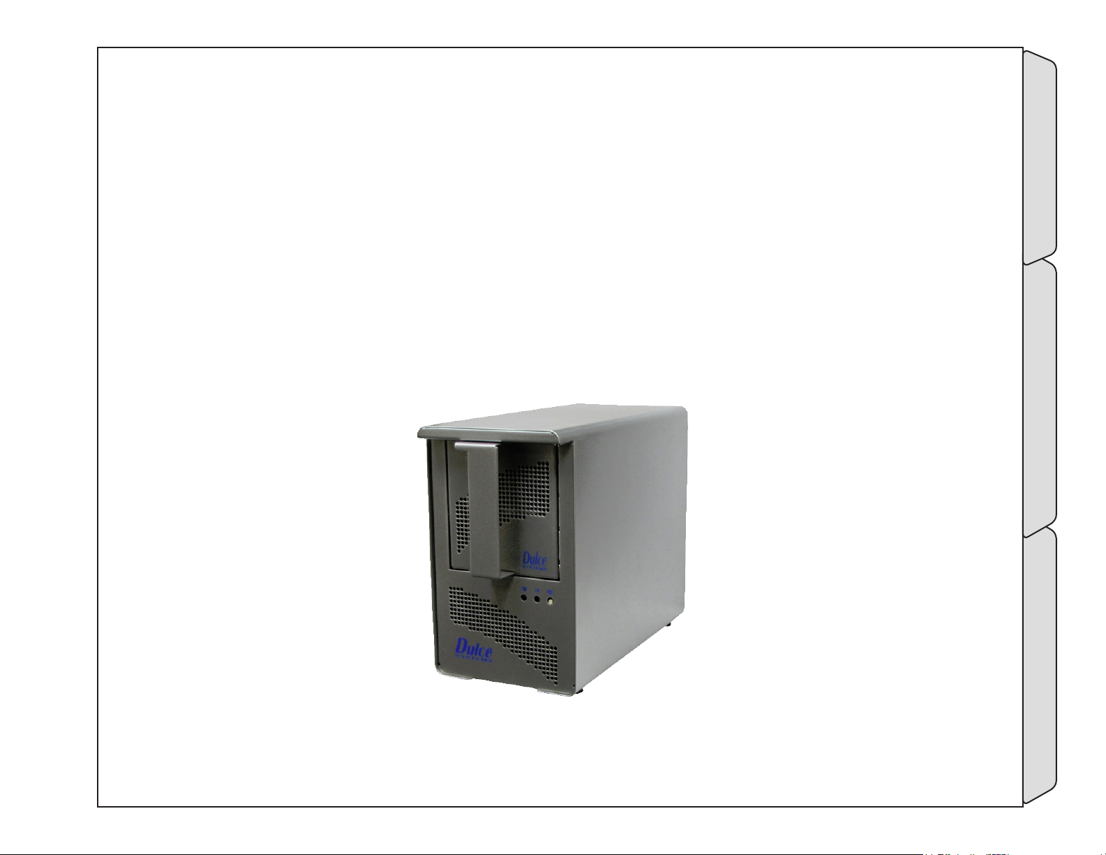
3.3.4 DAS Storage
If you have a need for local attached removable storage but need higher bandwidth than USB or eSATA and
would prefer a system designed for higher performance, another option may be DAS (Direct Attached Storage).
DAS utilizes a custom PCIe adapter card which connects directly to an external drive system. Because the card is
tied directly to the PCIe bus, the bandwidth can be very high. DAS generally utilizes a RAID array, leveraging the
high bus bandwidth to deliver high I/O performance accompanied by excellent file security.
Additionally, some DAS systems such as those from Dulce can also integrate a network adapter so while
the Cinedeck may only have one available PCIe slot, the installation of the DAS adapter will not necessarily
eliminate the addition of a network card.
The list too will grow however one manufacturer with DAS products known to be used with Cinedecks is Dulce
Systems.
DAS StorageRecording destinations Installation
Page - 46 of 297Cinedeck USER GUIDE - Cinedeck Version 4.5 13126 – June 15, 2015 - 19:21
Page 47
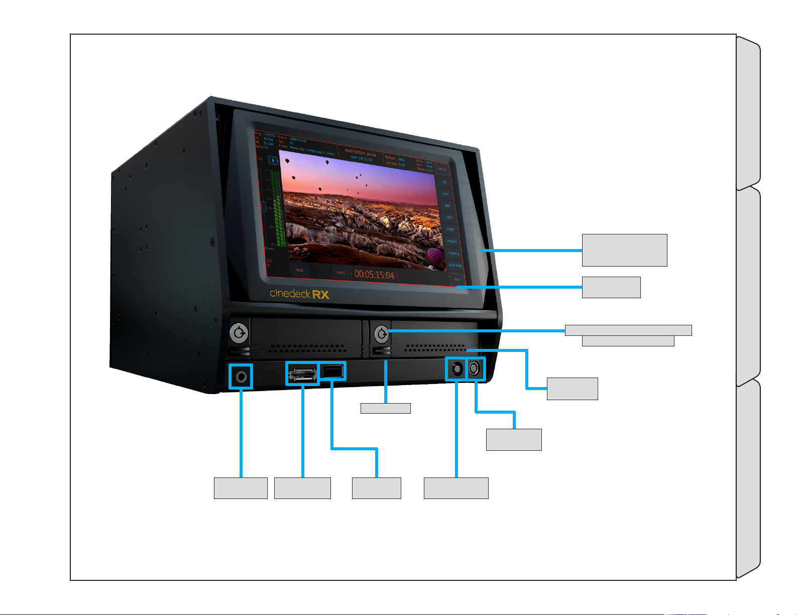
3.4 RX3G front panel
lCd sCreen Can be
TilTed down for HigH
raCKmoUnT posiTions
8- lCd display
- (p.48)
7- drive loCK & ejeCTor - (p.48)
Can be Key or TwisT loCK
1- HeadpHone
- (p.48)
2- esaTa porT
- (p.48)
drive ejeCTor
3- Usb porT
- (p.48)
6- drive Tray
- (p.48)
5- fUTUre Use
- (p.48)
-RX3G front panel Installation
4- power bUTTon
- (p.48)
Page - 47 of 297Cinedeck USER GUIDE - Cinedeck Version 4.5 13126 – June 15, 2015 - 19:21
Page 48
RX3G front panel / - cont...
Name Location Description
1- HeadpHone
2- esaTa porT
3- Usb porT
4- power bUTTon
5- fUTUre Use
6- drive Tray
7- drive loCK &
ejeCTor
8- lCd display
3.4 RX3G front
panel - (p.47)
3.4 RX3G front
panel - (p.47)
3.4 RX3G front
panel - (p.47)
3.4 RX3G front
panel - (p.47)
3.4 RX3G front
panel - (p.47)
3.4 RX3G front
panel - (p.47)
3.4 RX3G front
panel - (p.47)
3.4 RX3G front
panel - (p.47)
1/8” mini jack for use with standard stereo headphones.
* In the default factory configuration, this front port is disabled.
RX3G has a total of five internal SATA ports, the first four of which are by default used
for the SSD drive trays. The fifth SATA port is connected to eSATA 1 on the rear panel.
The front eSATA and rear eSATA 2 connectors can be enabled by swapping cables
internally. Please contact Cinedeck Support for more information.
Standard USB2 data port
In the default configuration, the power button requires a momentary push for turning
the RX3G on and off and glows blue when the system is running. The systems can
also manually be placed into Windows sleep mode. In this state, the power button will
blink slowly. Pressing the power button will wake the system.
Six pin Lemo connector for future features
RX3G can hold two removable drive trays. All current Cinedecks utilize these
removable drive trays, sometimes called sleds or carriers. Each tray can hold two SATA
SSD drives.
See “3.10 Inserting & ejecting drives” on page 69 and “3.3.1 SSDs” on page 42
The trays are also available separately.
Cinedecks are configured by default with twist-lock drive retainers but key-lock
retainers are available upon request with your initial order.
See “3.10 Inserting & ejecting drives” on page 69
1024 x 600 Touch Screen Display for user interface manipulation and video preview
of record and playback signals. This screen can be tilted to allow better viewing at
low angles. The same signals see on this screen can simultaneously be displayed on a
monitor connected to any one of the GUI display ports. You may need to access the
Windows “Screen Resolution“ settings to properly configure your external display.
-RX3G front panel Installation
Page - 48 of 297Cinedeck USER GUIDE - Cinedeck Version 4.5 13126 – June 15, 2015 - 19:21
Page 49
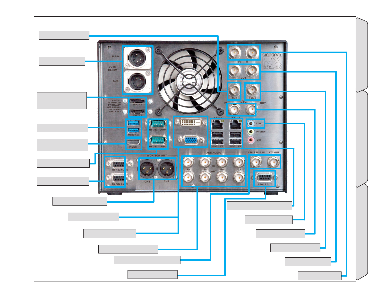
3.5 RX3G back panel
9- aUX 1/2 oUT - (p.50)
10- dC power - (p.50)
11- esaTa porTs - (p.50)
esaTa 1 = aCTive
12- Usb3 porTs - (p.50)
13- Hdmi for gUi -
(p.50)
14- rs-232 porTs - (p.50)
15- rs-422 porTs - (p.50)
16- moniTor oUT - (p.50)
17- dvi for gUi - (p.50)
18- vga for gUi - (p.50)
19- aes in & oUT - (p.50)
20- TimeCode opTion - (p.51)
21- rs-422 oUT - (p.51)
22- gb lan / Usb2 porTs - (p.51)
23- analog in - (p.51)
-RX3G back panel Installation
24- lTC in/loop - (p.51)
25- referenCe in - (p.51)
26- video oUT - (p.51)
27- video in - (p.51)
Page - 49 of 297Cinedeck USER GUIDE - Cinedeck Version 4.5 13126 – June 15, 2015 - 19:21
Page 50
RX3G back panel / - cont...
Name Location Description
9- aUX 1/2 oUT
10- dC power
11- esaTa porTs
12- Usb3 porTs
13- Hdmi for gUi
14- rs-232 porTs
15- rs-422 porTs
16- moniTor oUT
17- dvi for gUi
18- vga for gUi
19- aes in & oUT
3.5 RX3G back
panel - (p.49)
3.5 RX3G back
panel - (p.49)
3.5 RX3G back
panel - (p.49)
3.5 RX3G back
panel - (p.49)
3.5 RX3G back
panel - (p.49)
3.5 RX3G back
panel - (p.49)
3.5 RX3G back
panel - (p.49)
3.5 RX3G back
panel - (p.49)
3.5 RX3G back
panel - (p.49)
3.5 RX3G back
panel - (p.49)
3.5 RX3G back
panel - (p.49)
AUX video out is a secondary output of either channel 1 or channel 2. The signal
source selection can be defined on the “prefs” page of some systems.
RX3G has dual, wide range, DC inputs via XLR male connectors. Either input can be
used to operate the deck as they are auto switching. It is recommended to always
have power supplied to both inputs from separate power sources.
* In the default factory configuration, eSATA 2 on the back panel is disabled.
RX3G has a total of five internal SATA ports, the first four of which are by default used
for the SSD drive trays. The fifth SATA port is connected to eSATA 1 on the rear panel.
The front eSATA and rear eSATA 2 connectors can be enabled by swapping cables
internally. Please contact Cinedeck Support for more information.
Standard USB3 data ports. It is recommended to use USB2 ports when restoring a
system from the USB restore key.
The RX3G user interface can simultaneously be displayed on most HDMI monitors.
You may need to access the Windows “Screen Resolution“ settings to properly
configure your external display.
For remote control of most “broadcast” equipment, RS-422 will be used.
These ports can be used for connections between a Cinedeck and another computer
workstation such as an Avid or FCP system, eliminating the need for a RS-422 adapter.
One port per HD/SD channel. Each port can be used for remote control between a
tape deck or other professional device and a Cinedeck channel. The ports are bidirectional allowing “master mode” for the Cinedeck to control attached devices or
“slave mode“ allowing external devices to control the Cinedeck.
3-pin XLR Line-Level analog audio monitor output. One output per channel.
The RX3G user interface can simultaneously be displayed on most DVI monitors. You
may need to access the Windows “Screen Resolution“ settings to properly configure
your external display.
The RX3G user interface can simultaneously be displayed on most VGA monitors. You
may need to access the Windows “Screen Resolution“ settings to properly configure
your external display.
BNC AES audio in and out connectors where each connection carrys two AES
channels.
-RX3G back panel Installation
Page - 50 of 297Cinedeck USER GUIDE - Cinedeck Version 4.5 13126 – June 15, 2015 - 19:21
Page 51
RX3G back panel / - cont...
Name Location Description
The RX3G timecode option provides three additional features.
• Jam Sync - Similar to a camera, a timecode source can be momentarily
connected to this LTC input and RX3G will sync the internal generator to
that timecode.
• Timecode Out - With the timecode option, RX3G can generate and send
timecode to other connected devices such as cameras, eliminating the
20- TimeCode
opTion
21- rs-422 oUT
22- gb lan / Usb2
porTs
23- analog in
24- lTC in/loop
25- referenCe in
26- video oUT
27- video in
3.5 RX3G back
panel - (p.49)
3.5 RX3G back
panel - (p.49)
3.5 RX3G back
panel - (p.49)
3.5 RX3G back
panel - (p.49)
3.5 RX3G back
panel - (p.49)
3.5 RX3G back
panel - (p.49)
3.5 RX3G back
panel - (p.49)
3.5 RX3G back
panel - (p.49)
need to have a separate timecode generator, for example in a fly-pack type
of configuration.
• IRIG-B Timecode support - Allows RX3G to receive a IRIG-B timecode
source from an external IRIG-B timecode generator (not included) and
use that timecode data internally as a replacement for standard SMPTE
timecode.
You can confirm if your RX3G has the Timecode option if the BNC connectors are
included on the back panel and by checking in Windows Device Manager. If “AEC
Time Code device’ is listed, the deck has the option.
Unused
Two standard Gb Ethernet ports. Ports can be teamed in networks which support
teamed connections.
Four standard USB2 data connections.
An unbalanced analog line level audio input which can be used for recording stereo
scratch audio.
LTC (linear time code) input for use with a house supplied timecode signal. Signals
which are input are passed to the out connector.
For external reference, Cinedecks will lock to either standard color burst/black burst
or Tri-level sync. In “Auto“ mode, if no external reference is available, the deck will
default to internal sync or video input. In dual-link, when referencing to incoming
video, reference can be selected from the A or B input.
Channel 1 and 2, 3G video outputs. Can be paired and function as dual-link output.
Can optionally carry a video super with transport status, etc.
Channel 1 and 2, 3G video inputs. Each video input can accept up to 16 channels of
SDI embedded audio. Can be paired and function as dual-link input.
-RX3G back panel Installation
Page - 51 of 297Cinedeck USER GUIDE - Cinedeck Version 4.5 13126 – June 15, 2015 - 19:21
Page 52
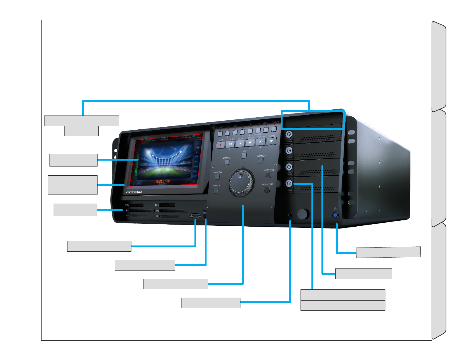
3.6 MX front panel
28- lCd ConTrol panel - (p.53)
noT sHown
29- lCd display -
(p.53)
lCd sCreen Can be
TilTed down for HigH
raCKmoUnT posiTions
30- Card readers -
(p.53)
31- esaTa porT - (p.53)
32- Usb3 porTs - (p.53)
33- ConTrol panel - (p.53)
34- HeadpHone - (p.53)
ower
37- p
36- drive Tray - (p.53)
35- drive loCK and ejeCTor - (p.53)
Can be Key or TwisT loCK
bUTTon
.53)
p
- (
-MX front panel Installation
Page - 52 of 297Cinedeck USER GUIDE - Cinedeck Version 4.5 13126 – June 15, 2015 - 19:21
Page 53
MX front panel / - cont...
Name Location Description
28- lCd ConTrol
panel
29- lCd display
30- Card readers
31- esaTa porT
32- Usb3 porTs
33- ConTrol panel
34- HeadpHone
35- drive loCK and
ejeCTor
36- drive Tray
37- power bUTTon
3.6 MX front panel
- (p.52)
3.6 MX front panel
- (p.52)
3.6 MX front panel
- (p.52)
3.6 MX front panel
- (p.52)
3.6 MX front panel
- (p.52)
3.6 MX front panel
- (p.52)
3.6 MX front panel
- (p.52)
3.6 MX front panel
- (p.52)
3.6 MX front panel
- (p.52)
3.6 MX front panel
- (p.52)
The MX LCD control panel has a LCD dimmer control and three pushbuttons; display
off/on toggle, menu access, selection and adjustment for size, etc..
1024 x 600 Touch Screen Display for user interface manipulation and video preview
of record and playback signals. This screen can be tilted to allow better viewing at
low angles. The same signals see on this screen can simultaneously be displayed on a
monitor connected to any one of the GUI display ports. You may need to access the
Windows “Screen Resolution“ settings to properly configure your external display.
Sony SxS, Panasonic P2 and Compact flash cards may be inserted for direct playback
and file management tasks such as copying data to local or network storage. The
Cinedeck will not write data to these cards with compatible file and folder structures
seen on natively written camera cards.
MX has a total of four eSATA ports, three on the rear panel, one on the front panel.
Standard USB3 port. It is recommended to use a rear USB2 port when restoring a
system from the USB system key.
Tactile machine interface control panel for transport control and channel selection.
See MX control panel for more information.
The image shown may not match your unit. Most MX systems have two mini and two
1/4” headphone jacks and two volume controls for audio monitoring.
Cinedecks are configured by default with twist-lock drive retainers but key-lock
retainers are available upon request with your initial order. See “3.10 Inserting &
ejecting drives” on page 69
MX can hold four removable drive trays. All current Cinedecks utilize these removable
drive trays, sometimes called sleds or carriers. Each tray can hold two SATA SSD drives.
See “3.10 Inserting & ejecting drives” on page 69 and “3.3.1 SSDs” on page 42
The trays are also available separately.
In the default configuration, the power button requires a momentary push for turning
the RX3G on and off and glows blue when the system is running. The systems can
also manually be placed into Windows sleep mode. In this state, the power button will
blink slowly. Pressing the power button will wake the system.
-MX front panel Installation
Page - 53 of 297Cinedeck USER GUIDE - Cinedeck Version 4.5 13126 – June 15, 2015 - 19:21
Page 54
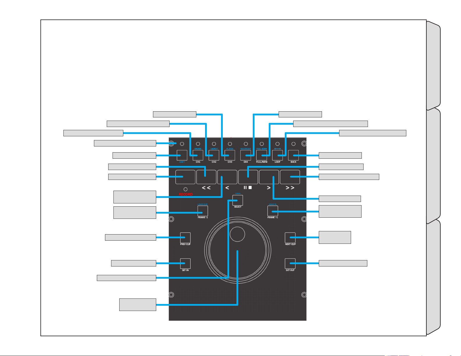
3.6.1 MX control panel
MX is a recording and playback appliance which provides the familiarity of a traditional tape machine by
including a full tactile jog-shuttle control panel and marries that with all of the unique Cinedeck capabilities.
The control panel three access methods: direct or single button commands such as play, and shuttle,
assignment functions such as first selecting Ch1 and then pressing stop to stop a recording and shift functions
(labeled in blue) like “shift + loop” to activate “ping pong” playback.
49- CH 2 | loCK Ui - (p.56)
48- CH 1 | on air - (p.56)
47- led indiCaTors - (p.55)
45- rewind - (p.55)
44- reCord - (p.55)
41- prev Clip - (p.55)
39- seleCT | open - (p.55)
46- sHifT - (p.55)
43- reverse play -
(p.55)
42- frame +1 |
load Clip - (p.55)
40- seT in - (p.55)
50- CH 3 - (p.56)
51- CH 4 - (p.56)
52- fUll/mini | fUll sCrn - (p.56)
53- loop | ping pong - (p.56)
54- baCK - (p.56)
55- paUse - (p.56)
56- forward fasT - (p.57)
57- play - (p.57)
58- frame +1 |
load pl - (p.57)
59- neXT Clip
- (p.57)
MX control panelMX front panel Installation
60- seT oUT - (p.57)
38- jog sHUTTle
Knob - (p.55)
Page - 54 of 297Cinedeck USER GUIDE - Cinedeck Version 4.5 13126 – June 15, 2015 - 19:21
Page 55
MX front panel / MX control panel cont...
Name Location Description
The MX jog /shuttle knob has two rotating parts, an inner disc with finger dent which
can be a continuously rotated and an outer ring which moves about ninety degrees in
38- jog sHUTTle
Knob
39- seleCT | open
40- seT in
41- prev Clip
42- frame +1 |
load Clip
43- reverse play
44- reCord
45- rewind
46- sHifT
47- led indiCaTors
“3.6.1 MX control
panel” on page
54
“3.6.1 MX control
panel” on page
54
“3.6.1 MX control
panel” on page
54
“3.6.1 MX control
panel” on page
54
“3.6.1 MX control
panel” on page
54
“3.6.1 MX control
panel” on page
54
“3.6.1 MX control
panel” on page
54
“3.6.1 MX control
panel” on page
54
“3.6.1 MX control
panel” on page
54
“3.6.1 MX control
panel” on page
54
each direction from the middle parked position.
View video frames slowly, frame by frame, by rotating the inner jog disc clockwise and
counter-clockwise. Clockwise rotations move forward in time.
Shuttle forward and reverse, to 20x speed, by rotating the outer ring clockwise and
counter-clockwise. Rotating in a clockwise direction moves forward in time.
A dual function button.
When shift is pressed first, opens selected clip or playlist.
When playing a clip or playlist and when working in the clip editor, in-points can be
directly set using “set-In”.
When viewing a playlist or multiple clips are loaded for playback, pressing “prev clip”
moves the playhead to the previous clip.
A dual function button.
In play mode, “frame + 1” moves playback of the current file forward one frame at a
time.
If shift is pressed first, clip manager is opened.
Plays the current file in reverse at 1x speed.
Starts recording on the assigned channel. It is required to press a channel number on
the top row and then press record to trigger recording on that channel.
Rewinds at 20x
The “shift” button must be pressed first to access any of the blue shift functions.
There are LED lamps positioned above the buttons to indicate which are active.
MX control panelMX front panel Installation
Page - 55 of 297Cinedeck USER GUIDE - Cinedeck Version 4.5 13126 – June 15, 2015 - 19:21
Page 56
MX front panel / MX control panel cont...
Name Location Description
A dual function button.
In normal mode, pressing “ch 1” assigns that channel to the control panel. Once
assigned, recording can be triggered and all transport controls are active for this
channel.
If “shift” is pressed before pressing “ch 1”, “on-air” mode can be toggled on and
off. When “on air” is active, no changes to channel settings are possible except
headphone monitoring selections. Any other screen or control panel actions will
trigger an “on air” warning message.
A dual function button.
In normal mode, pressing “ch 2” assigns that channel to the control panel. Once
assigned, recording can be triggered and all transport controls are active for this
channel.
If “shift” is pressed before pressing “ch 2”, the touchscreen interface can be locked or
unlocked. If locked, touching the screen will trigger an on screen “locked” warning.
Lock mode is primarily for use with the MX control panel which allows switching
channels while in lock mode.
Pressing “ch 3” assigns that channel to the control panel. Once assigned, recording
can be triggered and all transport controls are active for this channel.
Pressing “ch 4” assigns that channel to the control panel. Once assigned, recording
can be triggered and all transport controls are active for this channel.
A dual function button.
Pressing this button or pressing shift and then pressing this button, toggles the user
interface between multi channel view and single channel view.
A dual function button.
Pressing “loop” toggles loop playback mode on and off. Loop playback plays a file,
files or playlist continuously in the selected play direction.
Pressing shift and then “loop”, toggles ping pong playback on and off. Ping pong
playback plays the loaded file, files or playlist continuously from start to end to start.
Goes back to the previous screen
Pause stops playback but keeps the file loaded.
48- CH 1 | on air
49- CH 2 | loCK Ui
50- CH 3
51- CH 4
52- fUll/mini | fUll
sCrn
53- loop | ping
pong
54- baCK
55- paUse
“3.6.1 MX control
panel” on page
54
“3.6.1 MX control
panel” on page
54
“3.6.1 MX control
panel” on page
54
“3.6.1 MX control
panel” on page
54
“3.6.1 MX control
panel” on page
54
“3.6.1 MX control
panel” on page
54
“3.6.1 MX control
panel” on page
54
“3.6.1 MX control
panel” on page
54
MX control panelMX front panel Installation
Page - 56 of 297Cinedeck USER GUIDE - Cinedeck Version 4.5 13126 – June 15, 2015 - 19:21
Page 57
MX front panel / MX control panel cont...
Name Location Description
56- forward fasT
57- play
58- frame +1 |
load pl
59- neXT Clip
60- seT oUT
“3.6.1 MX control
panel” on page
54
“3.6.1 MX control
panel” on page
54
“3.6.1 MX control
panel” on page
54
“3.6.1 MX control
panel” on page
54
“3.6.1 MX control
panel” on page
54
Fast forwards the loaded file at 20x.
Plays the current file forward at 1x speed.
A dual function button.
In play mode, “frame + 1” moves playback of the current file forward one frame at a
time.
If “shift” is press first, playlist manager is opened.
When viewing a playlist or multiple clips are loaded for playback, pressing “next clip”
moves the playhead to the next clip.
When playing a clip or playlist and when working in the clip editor, out-points can be
directly set using “set-out”.
MX control panelMX front panel Installation
Page - 57 of 297Cinedeck USER GUIDE - Cinedeck Version 4.5 13126 – June 15, 2015 - 19:21
Page 58

3.6.2 -
This Page intentionally left blank.
-MX front panel Installation
Page - 58 of 297Cinedeck USER GUIDE - Cinedeck Version 4.5 13126 – June 15, 2015 - 19:21
Page 59
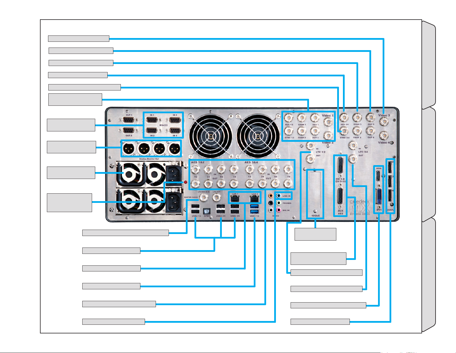
3.7 MX Back panel
61- video in 3&4 - (p.60)
62- video oUT 3&4 - (p.60)
63- sUper oUT 3&4 - (p.60)
64- aUX oUT 3/4 - (p.60)
65- referenCe in 3 & 4 - (p.60)
66- video i/o 1 & 2 -
(p.60)
67- rs-422 porTs -
(p.60)
68- moniTor oUT -
(p.60)
69- redUndanT power
- (p.60)
70- power sUpply
alarm ignore -
(p.60)
71- masTer TimeCode in & oUT - (p.61)
72- Usb2 porTs - (p.61)
73- gb eTHerneT - (p.61)
74- Usb3 porTs - (p.61)
75- aes in & oUT 1-16 - (p.61)
76- analog line in - (p.61)
77- opTional
neTworK - (p.61)
78- aes in & oUT 17-32
- (p.61)
79- lTC 1 & 2 in/loop - (p.61)
80- lTC 3 & 4 in/loop - (p.62)
81- dvi/Hdmi for gUi - (p.62)
82- esaTa porTs - (p.62)
-MX Back panel Installation
Page - 59 of 297Cinedeck USER GUIDE - Cinedeck Version 4.5 13126 – June 15, 2015 - 19:21
Page 60
MX Back panel / - cont...
Name Location Description
3G video inputs. Each video input can accept up to 16 channels of SDI embedded
audio. Can be paired and function as dual-link input.
All 4 inputs can be combined as 4K/UHD input.
3G video outputs. Can be paired and function as dual-link output.
All 4 outputs can be combined as 4K/UHD output.
HD/SD video outputs. Can carry video super with machine status, etc.
AUX video out is a secondary output of either channel 1 or channel 2. The signal
source selection can be defined on the “prefs” page of some systems.
For external reference, Cinedecks will lock to either standard color burst/black burst
or Tri-level sync. In “Auto“ mode, if no external reference is available, the deck will
default to internal sync or video input. In dual-link, when referencing to incoming
video, reference can be selected from the A or B input.
Same layout as Video 3 & 4, 38-42.
One port per HD/SD channel. Each port can be used for remote control between a
tape deck or other professional device and a Cinedeck channel. The ports are bidirectional allowing “master mode” for the Cinedeck to control attached devices or
“slave mode“ allowing external devices to control the Cinedeck.
3-pin XLR analog audio monitor output. One output per channel.
Dual, multi-voltage AC to DC power supplies. Either power supply can be used to
operate the deck as they are auto switching. It is recommended to always have power
supplied to both inputs from separate power sources.
If the deck is powered up with just one power supply connected or if a power supply
fails, a high pitch alarm will sound. Pressing the button will quiet the alarm.
61- video in 3&4
62- video oUT 3&4
63- sUper oUT 3&4
64- aUX oUT 3/4
65- referenCe in 3 & 4
66- video i/o 1 & 2
67- rs-422 porTs
68- moniTor oUT
69- redUndanT
power
70- power sUpply
alarm ignore
3.7 MX Back panel
- (p.59)
3.7 MX Back panel
- (p.59)
3.7 MX Back panel
- (p.59)
3.7 MX Back panel
- (p.59)
3.7 MX Back panel
- (p.59)
3.7 MX Back panel
- (p.59)
3.7 MX Back panel
- (p.59)
3.7 MX Back panel
- (p.59)
3.7 MX Back panel
- (p.59)
3.7 MX Back panel
- (p.59)
-MX Back panel Installation
Page - 60 of 297Cinedeck USER GUIDE - Cinedeck Version 4.5 13126 – June 15, 2015 - 19:21
Page 61
MX Back panel / - cont...
Name Location Description
The master timecode input provides four functions:
• Single timecode source - When selected on the master encode page of
the user interface, timecode fed to the master timecode input is directed to
all 4 channels.
• Jam Sync - Similar to a camera, a timecode source can be momentarily
connected to this LTC input and MX will sync the internal generator to that
71- masTer
TimeCode in & oUT
72- Usb2 porTs
73- gb eTHerneT
74- Usb3 porTs
75- aes in & oUT 1-16
76- analog line in
77- opTional
neTworK
78- aes in & oUT 17-32
79- lTC 1 & 2 in/
loop
3.7 MX Back panel
- (p.59)
3.7 MX Back panel
- (p.59)
3.7 MX Back panel
- (p.59)
3.7 MX Back panel
- (p.59)
3.7 MX Back panel
- (p.59)
3.7 MX Back panel
- (p.59)
3.7 MX Back panel
- (p.59)
3.7 MX Back panel
- (p.59)
3.7 MX Back panel
- (p.59)
timecode.
• Timecode Out - MX can generate and send timecode to other connected
devices such as cameras, eliminating the need to have a separate timecode
generator, for example in a fly-pack type of configuration.
• IRIG-B Timecode support - Allows MX to receive a IRIG-B timecode
source from an external IRIG-B timecode generator (not included) and
use that timecode data internally as a replacement for standard SMPTE
timecode.
Standard USB2 ports. It is recommended to use a USB2 port when restoring a system
from the USB system key.
Two standard Gb Ethernet ports. Ports can be teamed in networks which support
teamed connections.
Standard USB3 data ports. It is recommended to use USB2 ports when restoring a
system from the USB restore key.
8 AES channels per channel pair. Each BNC connection carries two AES channels.
An unbalanced analog line level audio input which can be used for recording stereo
scratch audio.
PCIe slot for installation of a 10Gb Ethernet card, 8 or 16Gb Fiber Channel card
or direct attached storage adapter.
An additional 16 AES channels can optionally be addressed via D-sub connectors.
LTC (linear time code) input to channels 1 and 2 for use with a house supplied
timecode signal. Signals which are input are passed to the out connector.
-MX Back panel Installation
Page - 61 of 297Cinedeck USER GUIDE - Cinedeck Version 4.5 13126 – June 15, 2015 - 19:21
Page 62
MX Back panel / - cont...
Name Location Description
80- lTC 3 & 4 in/
loop
81- dvi/Hdmi for gUi
82- esaTa porTs
3.7 MX Back panel
- (p.59)
3.7 MX Back panel
- (p.59)
3.7 MX Back panel
- (p.59)
LTC (linear time code) input to channels 3 and 4 for use with a house supplied
timecode signal. Signals which are input are passed to the out connector.
The MX user interface can simultaneously be displayed on most DVI or HDMI
monitors. You may need to access the Windows “Screen Resolution“ settings to
properly configure your external display.
MX has a total of four eSATA ports, three on the rear panel, one on the front panel.
-MX Back panel Installation
Page - 62 of 297Cinedeck USER GUIDE - Cinedeck Version 4.5 13126 – June 15, 2015 - 19:21
Page 63
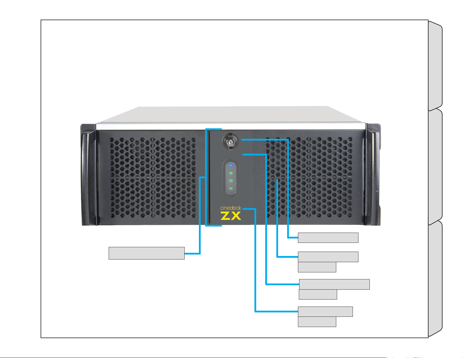
3.8 ZX Front panel
83- power and drive aCCess door
- (p.64)
84- door loCK - (p.64)
85- drive Trays - (p.64)
beHind door
-ZX Front panel Installation
86- power bUTTon - (p.64)
beHind door
87- Usb porT - (p.64)
beHind door
Page - 63 of 297Cinedeck USER GUIDE - Cinedeck Version 4.5 13126 – June 15, 2015 - 19:21
Page 64
ZX Front panel / - cont...
Name Location Description
83- power and
drive aCCess door
84- door loCK
85- drive Trays
86- power bUTTon
87- Usb porT
3.8 ZX Front panel
- (p.63)
3.8 ZX Front panel
- (p.63)
3.8 ZX Front panel
- (p.63)
3.8 ZX Front panel
- (p.63)
3.8 ZX Front panel
- (p.63)
The right hand door covers the power rocker switch and provides access to the drive
trays and a USB port.
Key lockable latch.
Turn to the right to open.
ZX can hold four removable drive trays. All current Cinedecks utilize these removable
drive trays, sometimes called sleds or carriers. Each tray can hold two SATA SSD drives.
The trays are also available separately.
See “3.10 Inserting & ejecting drives” on page 69 and “3.3.1 SSDs” on page 42
The trays are also available separately.
In the default configuration, the spring loaded power rocker switch requires a
momentary push down for turning ZX on and off. The lamps below the power button
glow when the system is running
Standard USB2 port.
-ZX Front panel Installation
Page - 64 of 297Cinedeck USER GUIDE - Cinedeck Version 4.5 13126 – June 15, 2015 - 19:21
Page 65
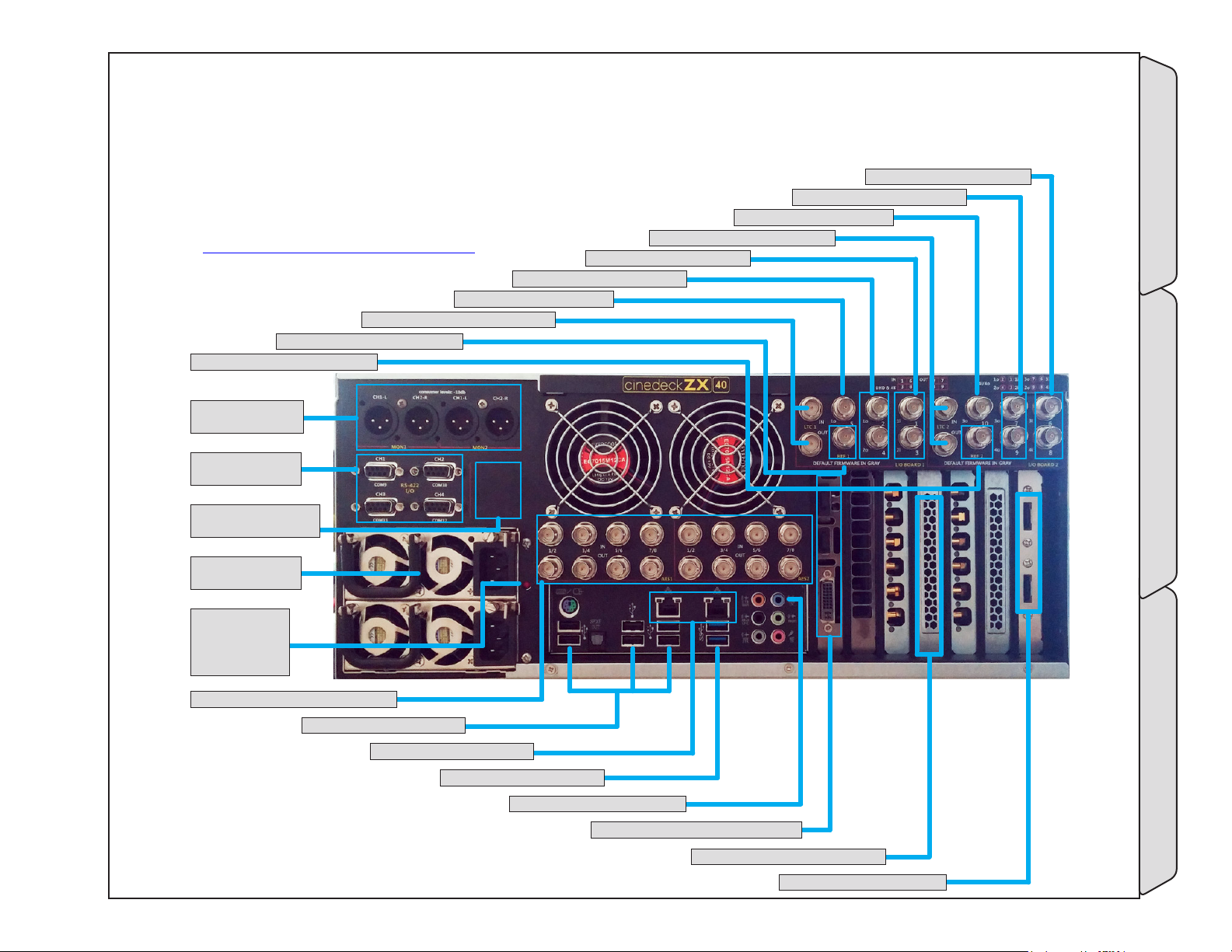
3.9 ZX Back panel
ZX has three base models and is a modular system so the back
panel on your ZX may differ from the ZX40 shown however
much of the connectivity is the same. If there are
questions, please contact Cinedeck directly.
See “Contacting Cinedeck” on page 2
94- aUX oUT 1/2 - (p.66)
95- lTC 1&2 in/loop - (p.66)
96- referenCe in 1&2 - (p.66)
97- referenCe in 3&4 - (p.66)
98- moniTor oUT -
(p.66)
99- rs-422 porTs
- (p.66)
100- masTer TimeCode
in & oUT - (p.67)
92- video in 1&2 - (p.66)
93- video oUT 1&2 - (p.66)
91- lTC 3&4 in/loop - (p.66)
88- video in 3&4 - (p.66)
89- video oUT 3&4 - (p.66)
90- aUX oUT 3/4 - (p.66)
101- redUndanT
power - (p.67)
102- power
sUpply alarm
ignore -
(p.67)
103- aes in & oUT 1-16 - (p.67)
104- Usb2 porTs - (p.67)
-ZX Back panel Installation
105- gb eTHerneT - (p.67)
106- Usb3 porTs - (p.67)
107- analog line in - (p.67)
108- dvi/Hdmi for gUi - (p.67)
109- opTional neTworK - (p.68)
110- esaTa porTs - (p.68)
Page - 65 of 297Cinedeck USER GUIDE - Cinedeck Version 4.5 13126 – June 15, 2015 - 19:21
Page 66
ZX Back panel / - cont...
Name Location Description
3G video inputs. Each video input can accept up to 16 channels of SDI embedded
audio. Can be paired and function as dual-link input.
All 4 inputs can be combined as 4K/UHD input.
3G video outputs. Can be paired and function as dual-link output.
All 4 outputs can be combined as 4K/UHD output.
AUX video out is a secondary output of either channel 1 or channel 2. The signal
source selection can be defined on the “prefs” page of some systems.
LTC (linear time code) input to channels 3 and 4 for use with a house supplied
timecode signal. Signals which are input are passed to the out connector.
3G video inputs. Each video input can accept up to 16 channels of SDI embedded
audio. Can be paired and function as dual-link input.
All 4 inputs can be combined as 4K/UHD input.
3G video outputs. Can be paired and function as dual-link output.
All 4 outputs can be combined as 4K/UHD output.
AUX video out is a secondary output of either channel 1 or channel 2. The signal
source selection can be defined on the “prefs” page of some systems.
LTC (linear time code) input to channels 1 and 2 for use with a house supplied
timecode signal. Signals which are input are passed to the out connector.
For external reference, Cinedecks will lock to either standard color burst/black burst
or Tri-level sync. In “Auto“ mode, if no external reference is available, the deck will
default to internal sync or video input. In dual-link, when referencing to incoming
video, reference can be selected from the A or B input.
For external reference, Cinedecks will lock to either standard color burst/black burst
or Tri-level sync. In “Auto“ mode, if no external reference is available, the deck will
default to internal sync or video input. In dual-link, when referencing to incoming
video, reference can be selected from the A or B input.
3-pin XLR analog audio monitor output. One output per channel.
One port per HD/SD channel. Each port can be used for remote control between a
tape deck or other professional device and a Cinedeck channel. The ports are bidirectional allowing “master mode” for the Cinedeck to control attached devices or
“slave mode“ allowing external devices to control the Cinedeck.
88- video in 3&4
89- video oUT 3&4
90- aUX oUT 3/4
91- lTC 3&4 in/
loop
92- video in 1&2
93- video oUT 1&2
94- aUX oUT 1/2
95- lTC 1&2 in/
loop
96- referenCe in 1&2
97- referenCe in 3&4
98- moniTor oUT
99- rs-422 porTs
3.9 ZX Back panel
- (p.65)
3.9 ZX Back panel
- (p.65)
3.9 ZX Back panel
- (p.65)
3.9 ZX Back panel
- (p.65)
3.9 ZX Back panel
- (p.65)
3.9 ZX Back panel
- (p.65)
3.9 ZX Back panel
- (p.65)
3.9 ZX Back panel
- (p.65)
3.9 ZX Back panel
- (p.65)
3.9 ZX Back panel
- (p.65)
3.9 ZX Back panel
- (p.65)
3.9 ZX Back panel
- (p.65)
-ZX Back panel Installation
Page - 66 of 297Cinedeck USER GUIDE - Cinedeck Version 4.5 13126 – June 15, 2015 - 19:21
Page 67
ZX Back panel / - cont...
Name Location Description
The master timecode input provides four functions:
• Single timecode source - When selected on the master encode page of
the user interface, timecode fed to the master timecode input is directed to
all 4 channels.
• Jam Sync - Similar to a camera, a timecode source can be momentarily
connected to this LTC input and MX will sync the internal generator to that
100- masTer
TimeCode in & oUT
101- redUndanT
power
102- power sUpply
alarm ignore
103- aes in & oUT 1-16
104- Usb2 porTs
105- gb eTHerneT
106- Usb3 porTs
107- analog line in
108- dvi/Hdmi for gUi
3.9 ZX Back panel
- (p.65)
3.9 ZX Back panel
- (p.65)
3.9 ZX Back panel
- (p.65)
3.9 ZX Back panel
- (p.65)
3.9 ZX Back panel
- (p.65)
3.9 ZX Back panel
- (p.65)
3.9 ZX Back panel
- (p.65)
3.9 ZX Back panel
- (p.65)
3.9 ZX Back panel
- (p.65)
timecode.
• Timecode Out - MX can generate and send timecode to other connected
devices such as cameras, eliminating the need to have a separate timecode
generator, for example in a fly-pack type of configuration.
• IRIG-B Timecode support - Allows MX to receive a IRIG-B timecode
source from an external IRIG-B timecode generator (not included) and
use that timecode data internally as a replacement for standard SMPTE
timecode.
Dual, multi-voltage AC to DC power supplies. Either power supply can be used to
operate the deck as they are auto switching. It is recommended to always have power
supplied to both inputs from separate power sources.
If the deck is powered up with just one power supply connected or if a power supply
fails, a high pitch alarm will sound. Pressing the button will quiet the alarm.
8 AES channels per channel pair. Each BNC connection carries two AES channels.
Standard USB 2 ports
Two standard Gb Ethernet ports. Ports can be teamed in networks which support
teamed connections.
Standard USB3 ports
An unbalanced analog line level audio input which can be used for recording stereo
scratch audio.
The ZX user interface can be displayed on most DVI or HDMI monitors. You may
need to access the Windows “Screen Resolution“ settings to properly configure your
external display.
-ZX Back panel Installation
Page - 67 of 297Cinedeck USER GUIDE - Cinedeck Version 4.5 13126 – June 15, 2015 - 19:21
Page 68
ZX Back panel / - cont...
Name Location Description
109- opTional
neTworK
110- esaTa porTs
3.9 ZX Back panel
- (p.65)
3.9 ZX Back panel
- (p.65)
PCIe slot for installation of a 10Gb Ethernet card, 8 or 16Gb Fiber Channel card
or direct attached storage adapter.
ZX can have a total of six, rear mounted eSATA ports.
-ZX Back panel Installation
Page - 68 of 297Cinedeck USER GUIDE - Cinedeck Version 4.5 13126 – June 15, 2015 - 19:21
Page 69
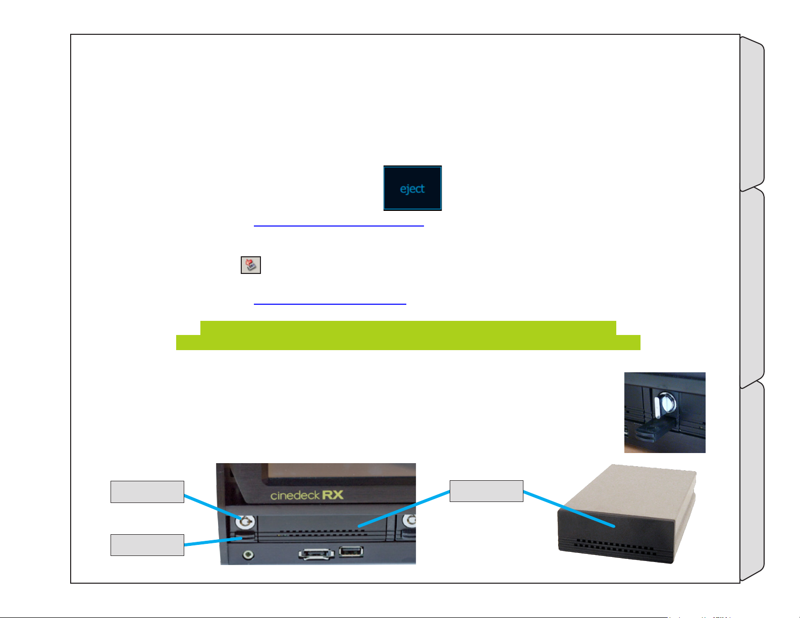
3.10 Inserting & ejecting drives
Before removing media drives from a Cinedeck, they should first be ejected from the operating system. This
can be done from the user interface via “clip manager” or from the Windows desktop via HotSwap.
To eject drives when the Cinedeck application is running:
Press “play” on the main multi or single screen view of the user interface to access “clip manager”. In “clip
manager”, select the drive to be ejected and select from the “manage disk” menu.
(For additional details, see “7.3 Clip manager” on page 211)
To eject drives from the Windows desktop:
Click the HotSwap! icon
in the System Tray and select the drive you want to eject. After a few moments, a
message will appear indicating “Safe to Hotswap” which means the drive can be removed.
(For additional details, see “5.5.3 HotSwap!” on page 84)
Remember that Cinedeck SSDs are often installed in pairs, two drives in a sled,
so be sure to check and if necessary eject both drives before removing the drive carrier.
The lock assembly consists of a twist or key lock and a drive ejector button. A twist lock is shown right
and a key lock is shown below. Your system may have either.
To remove a drive:
• If your system has twist locks, press the knob in gently, turn to the left until the knob clicks
into the vertical position and release the knob.
TwisT or Key loCK
drive ejeCTor
drive Carrier
-Inserting & ejecting drives Installation
Page - 69 of 297Cinedeck USER GUIDE - Cinedeck Version 4.5 13126 – June 15, 2015 - 19:21
Page 70
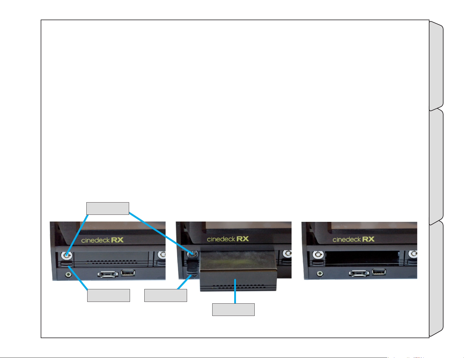
Inserting & ejecting drives / - cont...
• If your system has key locks, insert the key with the small pin locater pointing to the right, press the key
in and gently, turn to the left until the key is vertical.
• Gently press the drive ejector until a click is heard.
• Release the drive ejector, allowing it to extend out fully.
• Press the drive ejector firmly but slowly in to eject the drive from the deck.
To install a drive:
• If your system has twist locks, press the knob in gently and assure it is fully turned to the left and vertical.
• If your system has key locks, assure the locater slots are vertical or insert the key with the locater pin
pointing to the right, press the key in and gently, turn to the left until the key is vertical.
• Push the drive tray into the slot firmly, until it is flush with the front panel of the deck.
• If your system has twist locks, press the knob in gently, turn to the right until the knob clicks into the
horizontal position and release the knob.
• If your system has key locks, insert the key with the small pin locater pointing up, press the key in and
gently, turn to the right until the key is horizontal.
TwisT or Key loCK
drive ejeCTor
depressed
-Inserting & ejecting drives Installation
drive ejeCTor
eXTended
drive Carrier
Page - 70 of 297Cinedeck USER GUIDE - Cinedeck Version 4.5 13126 – June 15, 2015 - 19:21
Page 71
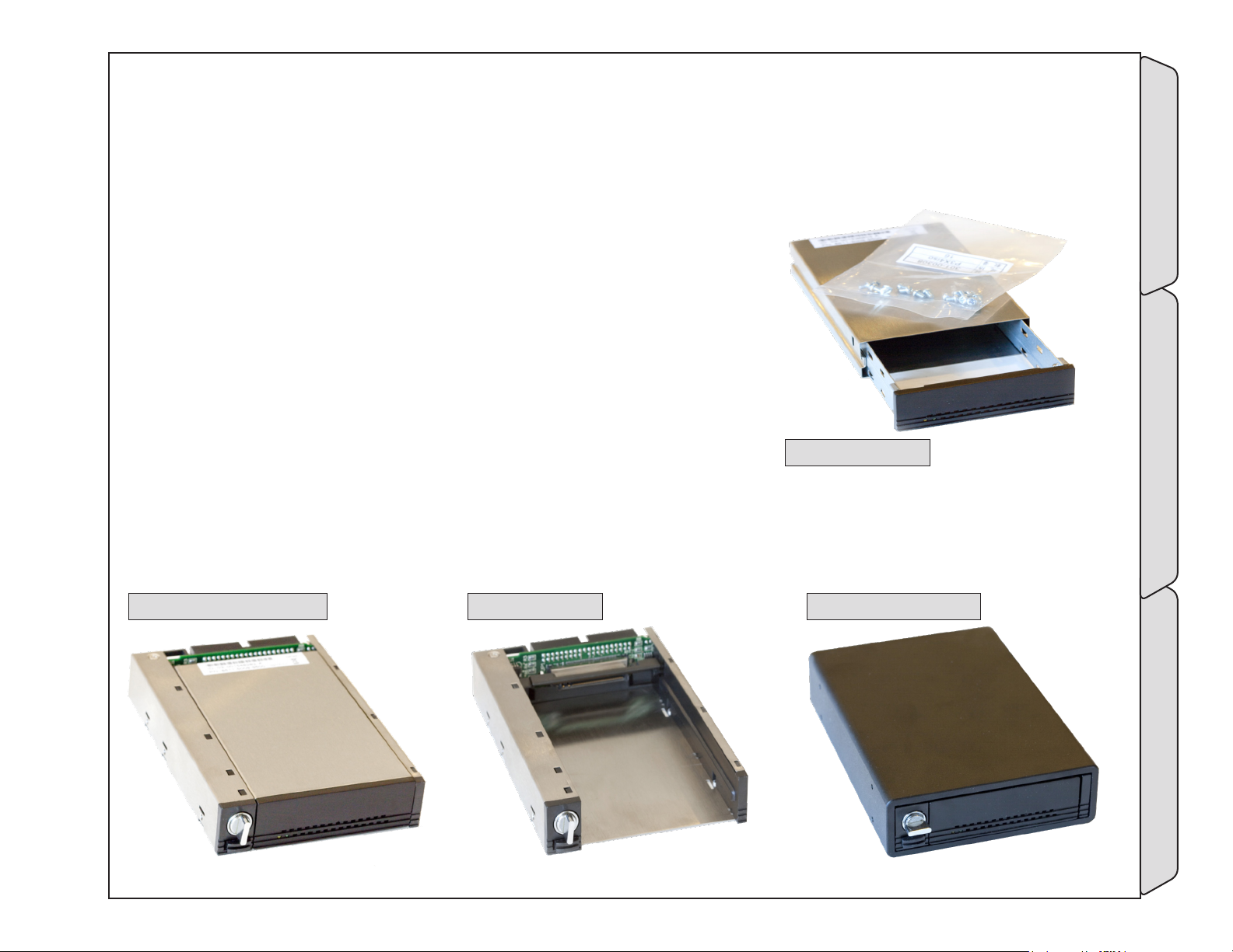
4.0 Accessories
4.1 Drive docks
For use in “sneaker-net” and other mobile applications, all Cinedecks make
use of hot-swappable drive carriers. Each carrier can hold two SSD drives.
The #15001 carriers are available separately and there are several receiving
docs which connect to computer workstations via SATA;
• 15000 Internal dock - Designed to fit a standard 3.5” drive bay in
a typical PC workstation has two SATA connections and a power
connection.
• 15002 Drive carrier and internal dock set - Includes the above dock
plus a drive carrier
• 15003 Rugged dock kit - Includes a drive carrier, power supply and
two eSATA cables
15001 drive Carrier
The docks are all available with twist lock (shown) or key lock.
Contact Cinedeck for additional information.
15002 drive doCK & Carrier 15000 drive doCK 15001 rUgged doCK KiT
-Drive docks Accessories
Page - 71 of 297Cinedeck USER GUIDE - Cinedeck Version 4.5 13126 – June 15, 2015 - 19:21
Page 72
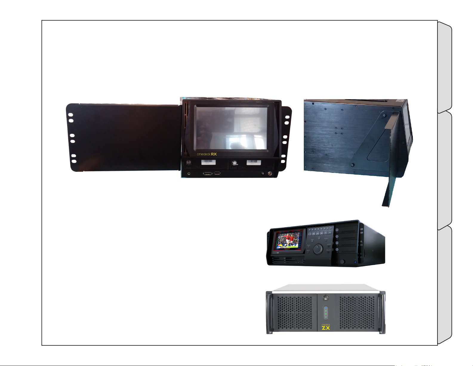
4.2 Rack mount kits
RX3G, MX and ZX can all be mounted in standard 19” equipment racks.
For RX, there are two rack kits available, a single machine kit with blank panel (shown) and a dual, side by side
kit.
The MX and ZX rack kits come with rack ears and side rack rails.
-Rack mount kits Accessories
Page - 72 of 297Cinedeck USER GUIDE - Cinedeck Version 4.5 13126 – June 15, 2015 - 19:21
Page 73
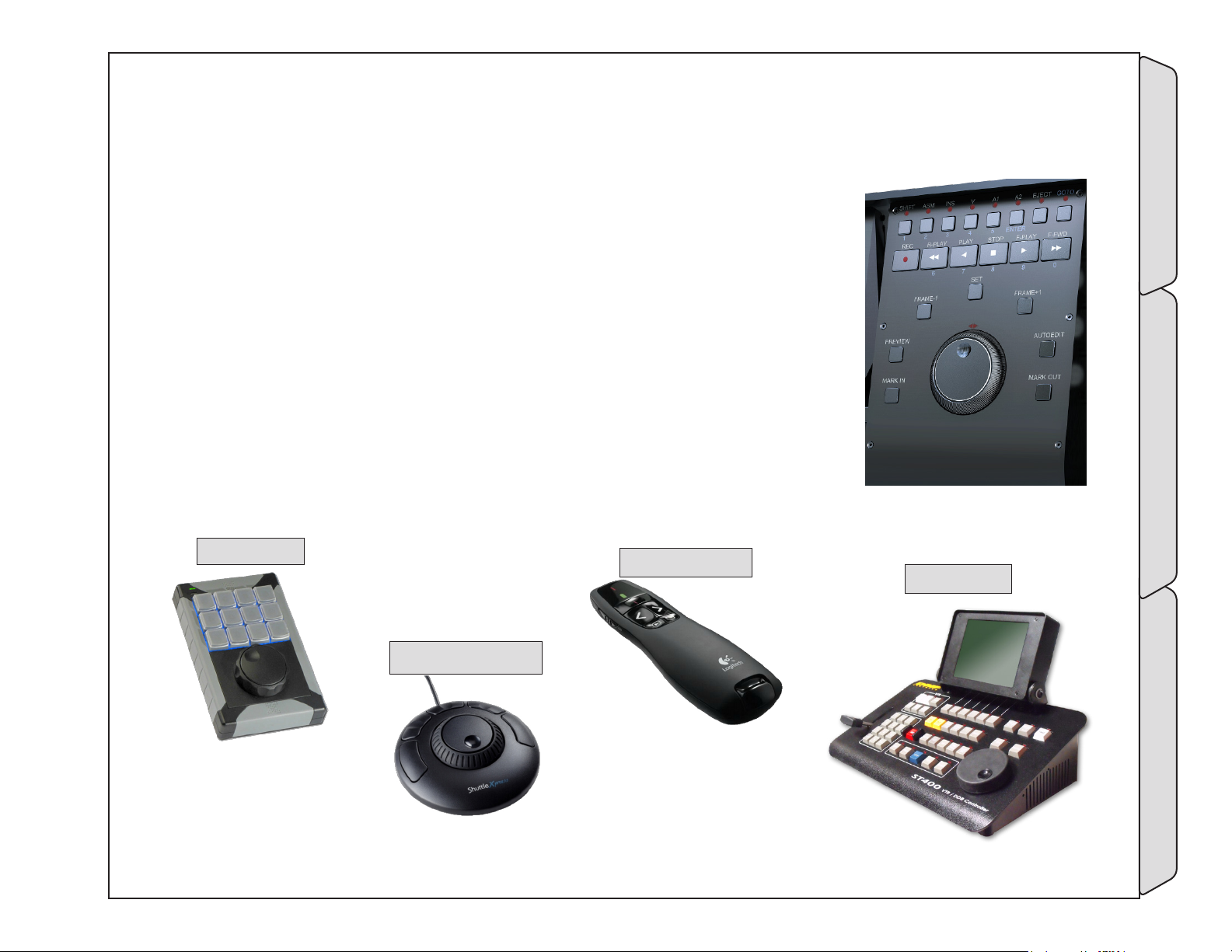
4.3 Control panels
Cinedecks can be controlled by an array of remote panels connected by USB and
RS-422. Additionally, ZX can be optionally equipped with a surface mount version
of the MX tactile control panel.
Third party controllers include;
X- Keys Jog- Shuttle XK- 12 controller by PI Engineering
(www.xkeys.com)
Shuttle Xpress and ShuttlePro V2 by Contour Designs
(www.contourdesigns.com)
Logitech R800 remote (www.logitech.com)
RS- 422 Device controllers include DNF ST100 and ST400 and those by JLCooper,
Lance Design, etc.
X-Keys XK-12
logiTeCH r800
dnf sT300
ConToUr designs
sHUTTle Xpress
-Control panels Accessories
Page - 73 of 297Cinedeck USER GUIDE - Cinedeck Version 4.5 13126 – June 15, 2015 - 19:21
Page 74

5.0 User Interface
5.1 UI Introduction
The Cinedeck user interface is uniquely designed to provide ease of access and operation for professional and
novice alike. After connecting and powering on your Cinedeck, there are generally just three things you must
do before you can make a recording;
• Set the input to match your source - this is generally done using “auto detect” on the input setup page
• Select a master and optionally proxy codec with wrapper and
• Designate a file destination drive - both of which are accomplished on the master and proxy setup pages.
Of course, Cinedeck systems go far beyond simply recording.
Those operators who have traditional video workflow experience combined with an understanding of the
IT aspects of modern video technology such as codecs, wrappers and network access, will have no problem
navigating and setting up a Cinedeck however, it is useful to have a basic understanding of the system...
The user interface is designed to be used by touchscreen or with a mouse. A USB keyboard is also very helpful
for data entry and system operation. Operation is the same whether you are using the built-in display or an
external display with a mouse.
Most important is that Cinedecks are project-centric meaning that for setup, everything you do is related to a
project which is associated to one or more channels. For example, if all four channels of a MX are associated to
the same project and you change the channel 3 codec from AVC-Intra to ProRes, all four channels are switched
to ProRes. Conversely, if all four channels need different codecs, you assign each channel to its own project.
The other important aspect is that while there is a default naming convention, Cinedecks impose virtually no
limitations on folder and file naming. To streamline setup, names which are editable such as “project” and
“input” are represented as “wildcards” (variables) which can be easily integrated into your folder and file naming
structure along with various run-time date and time elements.
A good understanding of the Project window, which is accessed via the main “overview” screen, is key to
acquiring files which fit your desired workflow.
Page - 74 of 297Cinedeck USER GUIDE - Cinedeck Version 4.5 13126 – June 15, 2015 - 19:21
-UI Introduction User Interface
Page 75
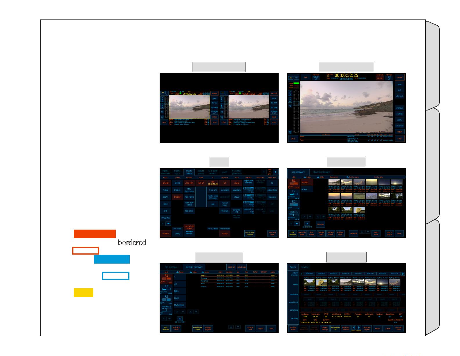
5.2 UI explained
Cinedecks utilize a GUI
(graphical user interface)
which consists of several
basic areas;
• The main / multi view
screen which, depending
on the Cinedeck model
and mode, can be one,
two or 4 quadrants.
• A single channel view.
• Multiple setup pages,
primarily accessed by
tabs across the top of the
setup screen.
• A clip manager screen.
• The playlist manager and
associated playlist editor.
mUlTi CHannel view single CHannel view
seTUp Clip manager
Some color generalizations:
• Bright orange items and
bright orange bordered
buttons are active.
• Bright aqua-green items
and bright aqua-green
bordered buttons are
inactive but available.
• Yellow items are
informational.
• Dim items and buttons
are not available or not
relevant.
playlisT manager playlisT ediTor
-UI explained User Interface
Page - 75 of 297Cinedeck USER GUIDE - Cinedeck Version 4.5 13126 – June 15, 2015 - 19:21
Page 76
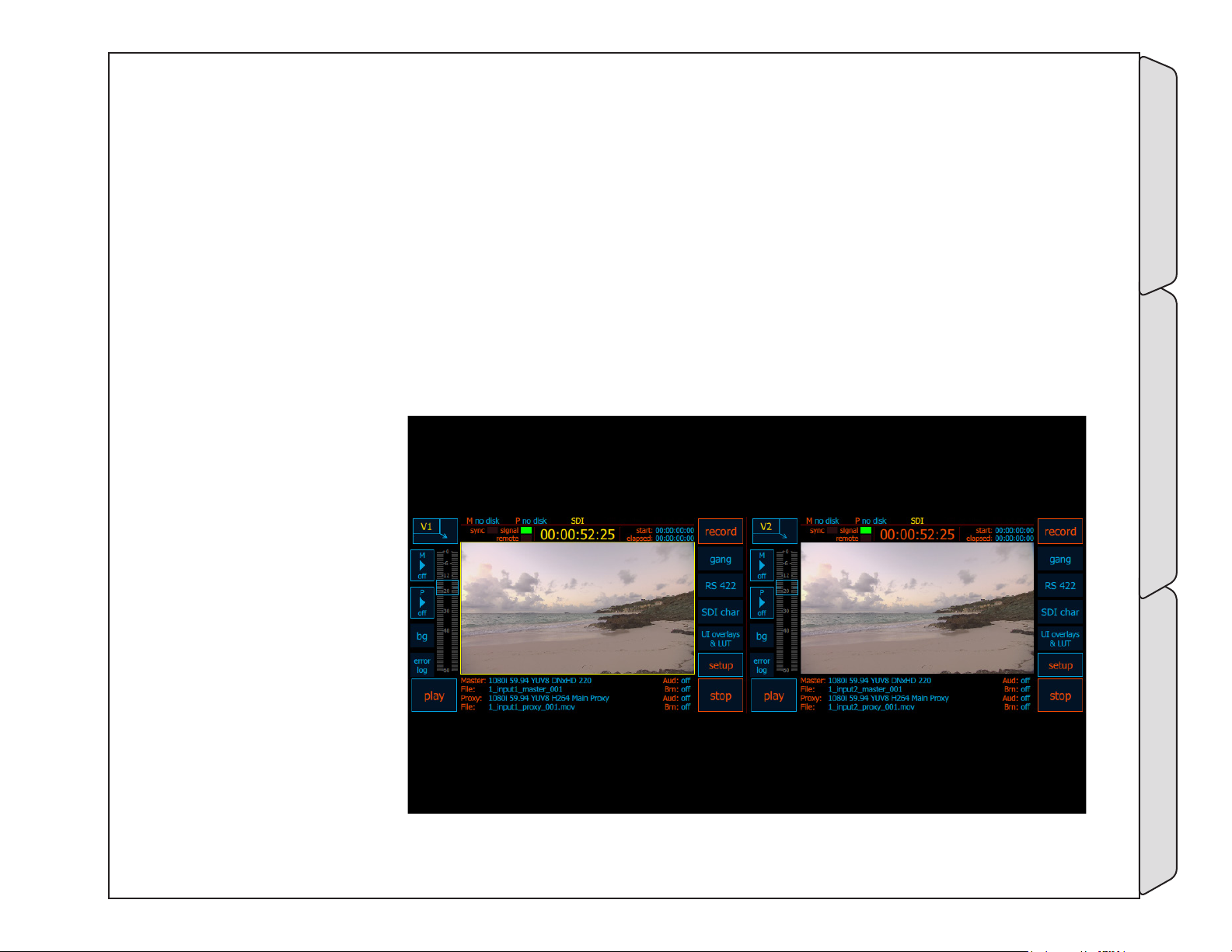
UI explained / - cont...
Beyond touching or clicking, the Cinedeck user interface also makes use of long presses (you might call these
shift functions) and screen hot spots. Additionally, there are a number of keyboard shortcuts and bar-code
readers can be utilized for data entry.
The most notable long press action is to stop a recording. When a system is recording and setup with the
default “prefs” configuration, simply clicking stop will have no effect. A long press of about 2 seconds is
required to stop the recording. This eliminates accidental stops, particularly with touch screen systems.
There are other long press functions which will be noted throughout the manual.
Screen hot spots are areas of a screen which, when touched, will direct the operator directly to the related
setup area or which display additional information. Both will be detailed more fully in this manual but as an
example, touching the file information at the bottom of this screen, changes the display from showing the
selected master and proxy
encode details and file
names to the folder path
and duration. Touching
that area again will toggle
to show the current project
name, scene and sub-scene
names.
If your facility uses barcodes and, for example,
are transferring tapes
to files, an appropriate
HID compatible bar-code
reader can be used to
enter data into selected
fields such as file name,
directly from the bar-code
information.
-UI explained User Interface
Page - 76 of 297Cinedeck USER GUIDE - Cinedeck Version 4.5 13126 – June 15, 2015 - 19:21
Page 77
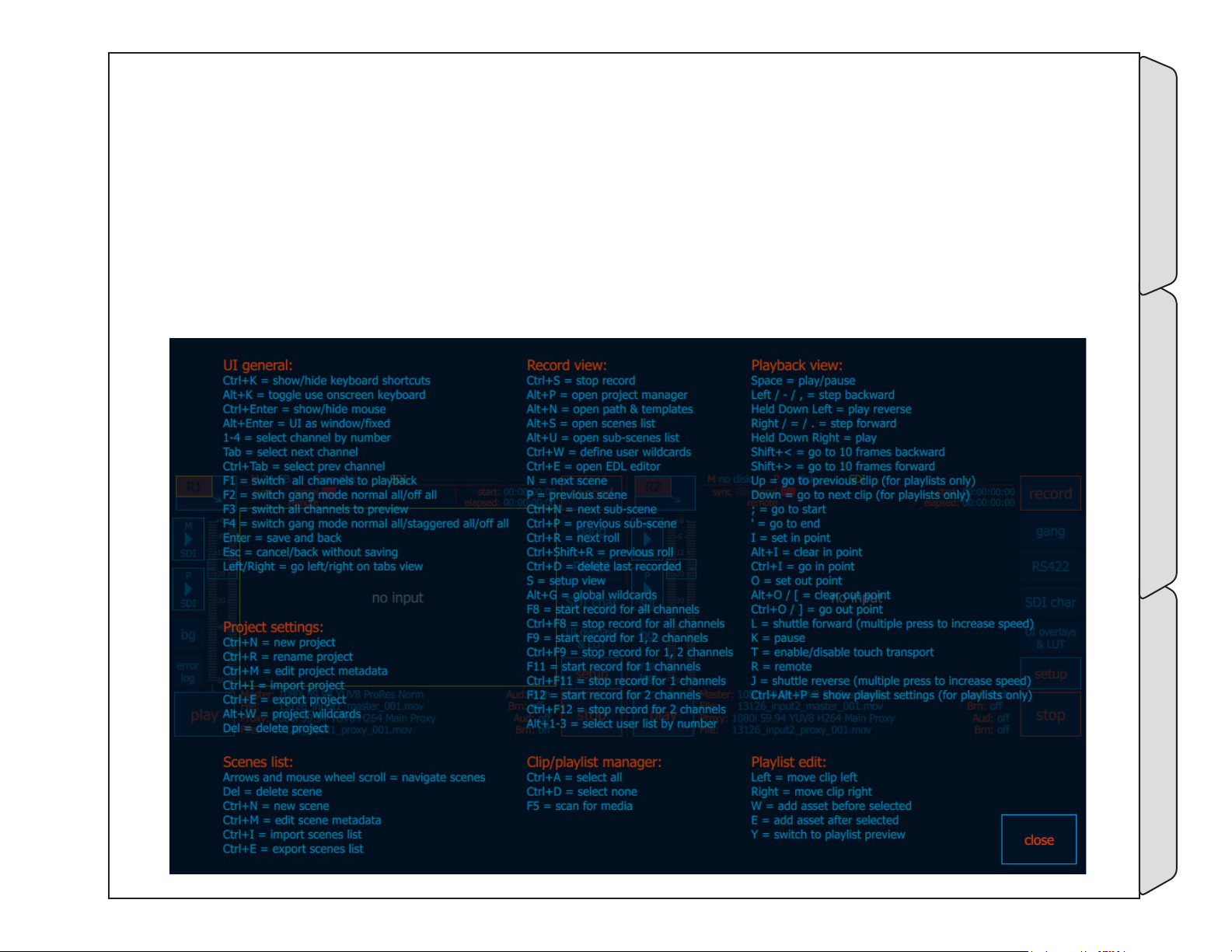
5.3 Keyboard shortcuts
The Cinedeck user interface can be driven to a great extent using shortcut key presses on an attached USB
keyboard.
Press control plus K “Control+K” to open this on-screen listing of available shortcuts.
As can be seen from this screen, the available shortcuts are different based on the operating mode and visible
screen but some general shortcuts such as “Enter” to save and return to the previous screen and “Escape” to
cancel changes and return to the previous screen remain available across most screens.
-Keyboard shortcuts User Interface
Page - 77 of 297Cinedeck USER GUIDE - Cinedeck Version 4.5 13126 – June 15, 2015 - 19:21
Page 78
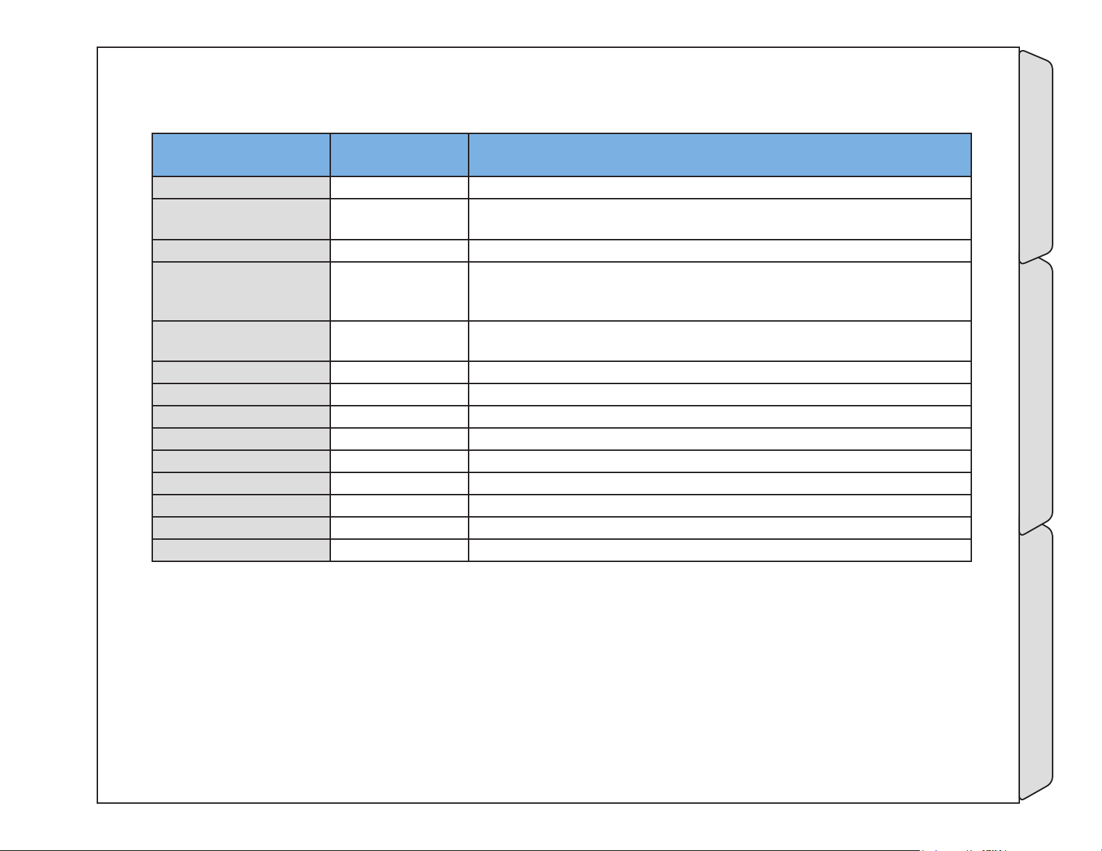
Keyboard shortcuts / - cont...
User Interface
Available in: Description
General Shortcuts
Control+K most screens Toggle the display of the keyboard shortcuts overview screen
Alt+K “
Control+Enter “ Toggles showing or hiding the mouse cursor
Alt+Enter “
Number keys 1, 2, 3 4, “
Tab “ Selects / displays the next channel
Control+Tab “ Selects / displays the previous channel
F1 “ Switch all channels to playback mode
F2 “ Toggle gang mode ‘normal’ On/Off for all channels
F3 “ Switch all channels to preview - EtoE mode
F4 “ Toggle gang mode ‘staggered’ On/Off for all channels
Enter “ Save any changes and return to the previous screen
Escape “ Cancel any changes and return to the previous screen
Right and Left arrow Setup screens Switch to next or previous tab in setup screens
Toggles between using the on-screen keyboard or direct field typing, for
data entry areas such as creating file names
Toggles the user interface window mode. Normally the Cinedec interface
runs full screen, pressing Alt+Enter puts the interface into a standard MS
Windows re-sizable frame
Directly selects the active and visible channel by number. The numbers
above the QWERTY keys or the numeric keypad can be used
-Keyboard shortcuts User Interface
Page - 78 of 297Cinedeck USER GUIDE - Cinedeck Version 4.5 13126 – June 15, 2015 - 19:21
Page 79
Keyboard shortcuts / - cont...
Project Settings
Available in: Description
Shortcuts
Control+N Project manager Create new project
Control+R “ Rename current project
Control+M “ Edit project metadata such as director and director of photography
Control+I “ Import current project
Control+E “ Export current project
Alt+W “ Open ‘user wildcards’ management
Alt+G “ Open ‘global wildcards’ management
Control+L
Control+U
DEL Project manager Delete selected project
path & filename
templates
path & filename
templates
Lock current selected project
Unlock current selected project
Scenes List Shortcuts Available in: Description
Arrow keys and mouse
scroll wheel
Del “ Delete selected scene
Control+N “ Create new scene
Control+M “ Edit scene metadata
Control+I “ Import scenes list
Control+E “ Export scenes list
Scene list manager
Navigate scenes list
-Keyboard shortcuts User Interface
Page - 79 of 297Cinedeck USER GUIDE - Cinedeck Version 4.5 13126 – June 15, 2015 - 19:21
Page 80
Keyboard shortcuts / - cont...
Record / Preview
Available in: Description
Shortcuts
Control+S Record View Stops recording on all channels
Alt+P “ Open project manager main page
Alt+N “ Open path & templates screen for folder and file naming
Alt+S “ Open scenes list manager
Alt+U Open sub-scenes list manager
Alt+W Open ‘user wildcards’ manager
Alt+G Open ‘global wildcards’ management
Ctrl+E Opens EDL Editor
N Switch naming to next scene name
P Switch naming to previous scene name
Ctrl+N Switch naming to next sub-scene name
Ctrl+P Switch naming to previous sub-scene name
Ctrl+R Increment naming to next roll number
Ctrl+Shift+R Increment naming to previous roll number
Ctrl+D Delete last recorded clip on all channels
S Go to Setup
F8 Start recording on all channels
Ctrl+F8 Stop recording on all channels
Alt+1, 2 or 3 Open list manager for user list 1, 2 or 3 respectively
Clip & Playlist
Available in: Description
Manager Shortcuts
Control+A
Control+D “ Select no clips
F5 “ Scan selected drive or folder for media
Clip & Playlist
manager
Select all clips
-Keyboard shortcuts User Interface
Page - 80 of 297Cinedeck USER GUIDE - Cinedeck Version 4.5 13126 – June 15, 2015 - 19:21
Page 81
Keyboard shortcuts / - cont...
Playback Shortcuts Available in: Description
Space bar Playback view Toggle play and pause
Left arrow or “-” key “ Step backwards one frame
Left arrow (long press) Play 1x speed backwards
Right arrow or “=” key “ Step forwards one frame
Right arrow (long press) Play 1x speed forwards
Shift+< Step backwards 10 frames
Shift+> Step forwards 10 frames
Up arrow Playback/Playlist GoTo previous clip
Down arrow Playback/Playlist GoTo next clip
; (semi-colon) “ GoTo start of clip
‘ (apostrophe) “ GoTo end of clip
I “ Set in-point
Alt+I Clear in-point
Ctrl+I Go to in-point
O “ Set out-point
Alt+O Clear out-point
Ctrl+O Go to out-point
J Play in reverse (Multiple presses increases speed)
K Pause playback
L “ Play forward (Multiple presses increases speed)
T “ Enable / disable touch transport
Control+Alt+P Playback/Playlist Show playlist settings
Playlist Shortcuts Available in: Description
Left Arrow Playlist Editor Move selected clip left
Right Arrow “ Move selected clip to right
W “ Add clip asset before selected clip
E “ Add clip asset after selected clip
Y “ Switch to playlist preview screen
-Keyboard shortcuts User Interface
Page - 81 of 297Cinedeck USER GUIDE - Cinedeck Version 4.5 13126 – June 15, 2015 - 19:21
Page 82
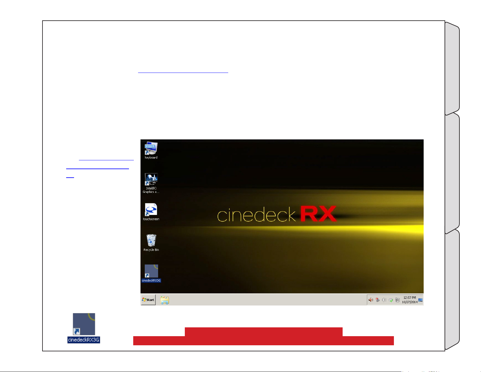
5.4 Powering on
For the location of the power button on your specific Cinedeck, please refer to the appropriate front panel
description in chapter “3.0 Installation” on page 37.
Current Cinedecks run a Windows 7 embedded operating system, installed on a separate SSD, set as drive
c:\. After pressing the power button, the Cinedeck will go through several internal BIOS and hardware related
checks and then boot into Windows. From the factory, most Cinedecks boot to the Windows desktop however
RX3G may boot directly into the Cinedeck application. If your system has, for example, been setup to operate
in your facilities domain, you may need a password in order to access the desktop or start the Cinedeck
application. If a password is required, contact your engineering or IT staff responsible for your production
systems. If no
keyboard is available,
see “5.5.1 On-screen
keyboard” on page
83
All Cinedeck
desktops look similar
and from here, many
of the standard
Windows programs
such as Windows
Explorer are available.
If you need to setup
network connections,
it is best to do so
before starting the
Cinedeck application.
To start the Cinedeck from the desktop, locate and double click the Cinedeck short cut.
-Powering on User Interface
If this is your first experience with a Cinedeck,
please review the next section first before starting the Cinedeck application.
Page - 82 of 297Cinedeck USER GUIDE - Cinedeck Version 4.5 13126 – June 15, 2015 - 19:21
Page 83
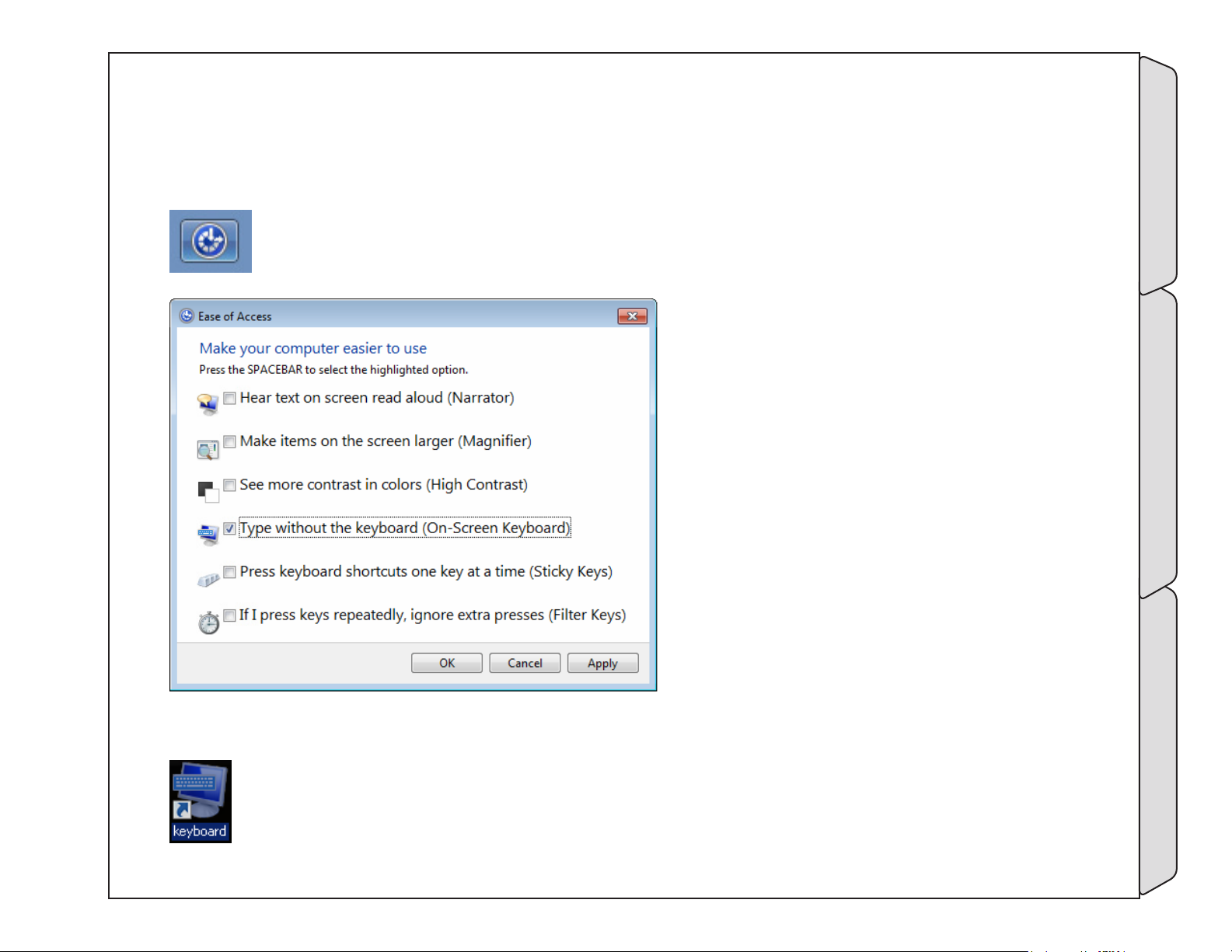
5.5 Desktop details
5.5.1 On-screen keyboard
Your system may have additional options but all systems include several useful links on the desktop.
First, if you have a touch screen system and are stuck at the Windows login without a USB keyboard on hand,
Click the “Ease of Access” icon found at the lower left of the Windows log-in screen.
From the Ease of access menu, touch
“Type without keyboard” and select “OK”.
The keyboard will open.
Touch to select the password field and then use
the keyboard to fill in the data.
Once you are at the Windows desktop...
This shortcut starts the on-screen keyboard which is usable across the Windows environment.
As noted above, for systems with touch screens, the keyboard can also be accessed from the Windows log-on
screen to allow the entering of a password without a USB keyboard attached.
Page - 83 of 297Cinedeck USER GUIDE - Cinedeck Version 4.5 13126 – June 15, 2015 - 19:21
On-screen keyboardDesktop details User Interface
Page 84
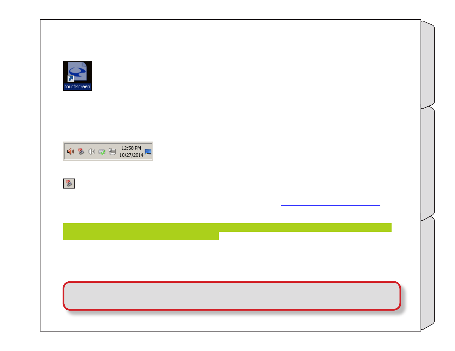
5.5.2 Touchscreen setup
The touchscreen shortcut opens the properties and adjustment application for calibrating the built-in
user interface touch display available on RX3G and MX systems.
See “9.2 Touchscreen calibration” on page 241
5.5.3 HotSwap!
The system Tray located on the Windows Task Bar includes several items
including access to the SATA drive hot-swap system.
SATA HotSwap allows easy disconnect and removal of SATA drives connected to the Cinedeck system from
the Windows desktop.
(Drives can also be ejected from within the Cinedeck user interface. See “450- manage disk” on page 214)
To remove a drive from the system, click the HotSwap! icon and select the drive you want to eject. After a few
moments, a message will appear indicating “Safe to Hotswap” which means the drive can be removed.
When preparing to remove a SSD, keep in mind that your Cinedeck may have two drives installed in the tray
you want to remove so be sure to eject both drives.
When connecting a new SATA drive the system will generally automatically detect it however occasionally, it
may be necessary to force the system to rescan for new hardware to make the drive accessible.
To do this, right click the HotSwap icon and select “Scan for hardware changes”.
Touchscreen setupDesktop details User Interface
Important! If you do not see the HotSwap! icon in your system tray, please contact Cinedeck
support as this is an important background service which should be running on all systems.
Page - 84 of 297Cinedeck USER GUIDE - Cinedeck Version 4.5 13126 – June 15, 2015 - 19:21
Page 85
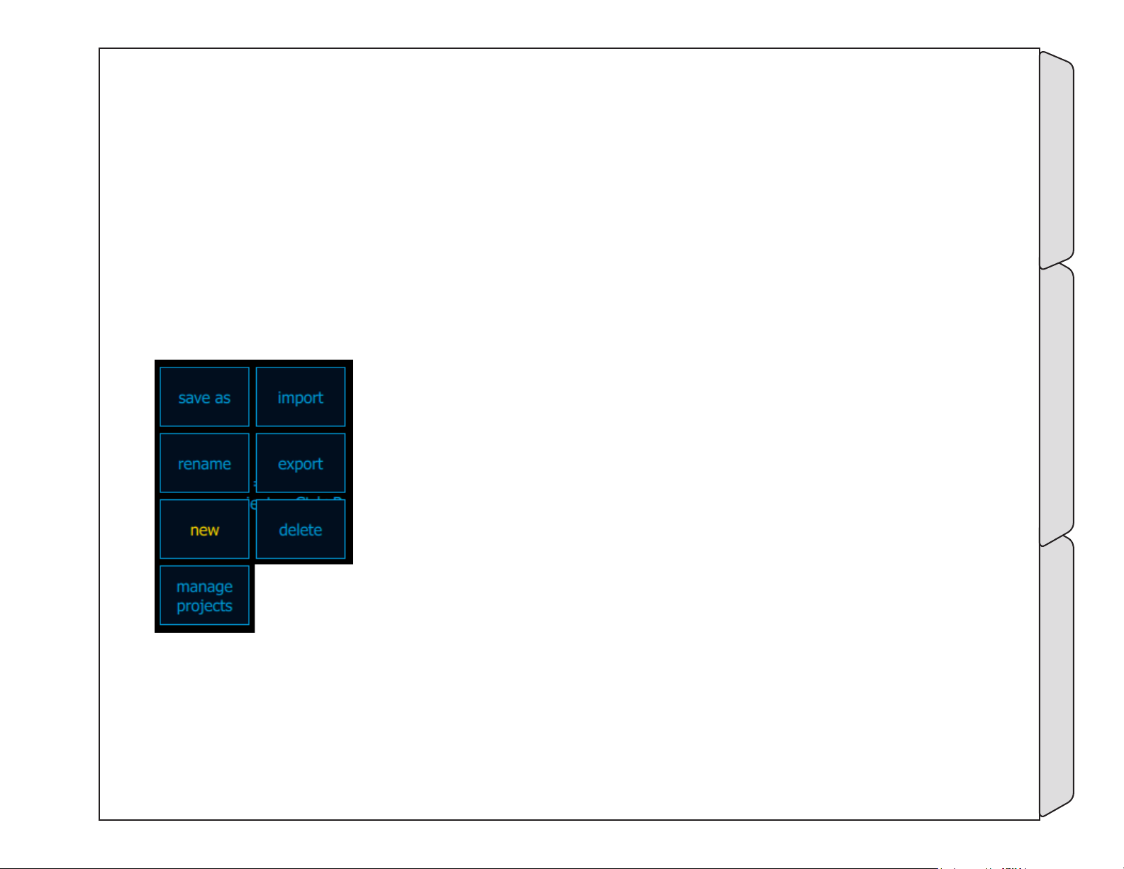
5.6 Settings - exporting / importing
In many areas of the Cinedeck system such as project settings, scene names, LUT and so on, it is possible to
save, export and/or import data. While the specifics of the data can change the procedure for saving, naming
and importing remains the same.
Some settings are by default saved in a sub folder of the Cinedeck install folder; c:\cinedeck. For example,
project settings are by default saved in c:\cinedeck\projects. That is the projects folder under the main Cinedeck
folder. LUT files are also by default, looked for in the “LUT” folder under c:\cinedeck.
But all of the files you might need to work with can be saved to or retrieved from your preferred media and
location such as one of your media drives, a network folder or simply a newly inserted USB memory stick.
Most often, you will have access to the various save functions via a menu located at the lower left of the screen.
As an example, these are the functions available from “manage projects”.
All options will not be available on every menu but they are all similar.
Whether you select “save as” or “export”, the procedure is the same and is made
in two steps however “save as” places the file in the default folder location while
export provides full flexibility as to the destination used.
1. At the next dialog after you select “save as” or “export”, you must enter a
name in the “name” field. This can be any standard name acceptable to Windows
but again, for word separation it is recommended to use “_” or “-” and not spaces.
Once you have entered a name with either the on-screen or USB keyboard and
selected “save and close”,
2. Select a destination drive and folder at the left and once the file destination
drive and folder are determined, select save at the bottom right and you are done.
Importing a file such as a scenes list or opening a file such as a LUT is the same procedure in reverse.
• Select “import” or “open”
• Navigate to the source drive and folder and select the required file
• Select open or import
There are a few important things to note;
-Settings - exporting / impor ting User Interface
Page - 85 of 297Cinedeck USER GUIDE - Cinedeck Version 4.5 13126 – June 15, 2015 - 19:21
Page 86

Settings - exporting / importing / - cont...
When importing lists such as scenes or sub-scenes, the import will overwrite any existing list items you currently have
associated with that project.
When opening LUT files, it is recommended to first copy the required LUT files onto a drive which will always be available
to the system. The easiest is to use the default location, c:\cinedeck\LUT. This is the LUT folder in the main c:\cinedeck
install folder and is the location which will first open when you look for LUT files.
Cinedeck uses several specific file name extensions for Cinedeck specific files. Be aware that there is always the possibility
that other applications on your system will also use the same file extension. This not an issue unless you accidentally
tell Windows to always use some particular application for opening that file type. In that case, files may no longer
automatically open in that other application. For example, if you were to tell Windows to always open .txt files with Excell,
Notepad would no longer automatically be used.
The main file extensions used within the Cinedeck system are:
• *.cdl - Cinedeck EDL (edit decision list) - plain comma delineated ASCII text file
CMX 3600 EDLs can also be imported
• *.csv - can be imported as EDL
• *.csl - Cinedeck scenes and sub-scenes list (XML format)
• cinedeck.db - a sql databased used to track content
• *.dmp - Crash dump files
• prefs.ini - holds basic system and mode parameters (If deleted, this file will be rebuilt on restart)
• *.xml - XML formatted project files, channel files, etc
• *.txt - Log files are saved as txt files
• *.cube - Cinedecks currently only recognize .cube LUT files
-Settings - exporting / impor ting User Interface
Page - 86 of 297Cinedeck USER GUIDE - Cinedeck Version 4.5 13126 – June 15, 2015 - 19:21
Page 87
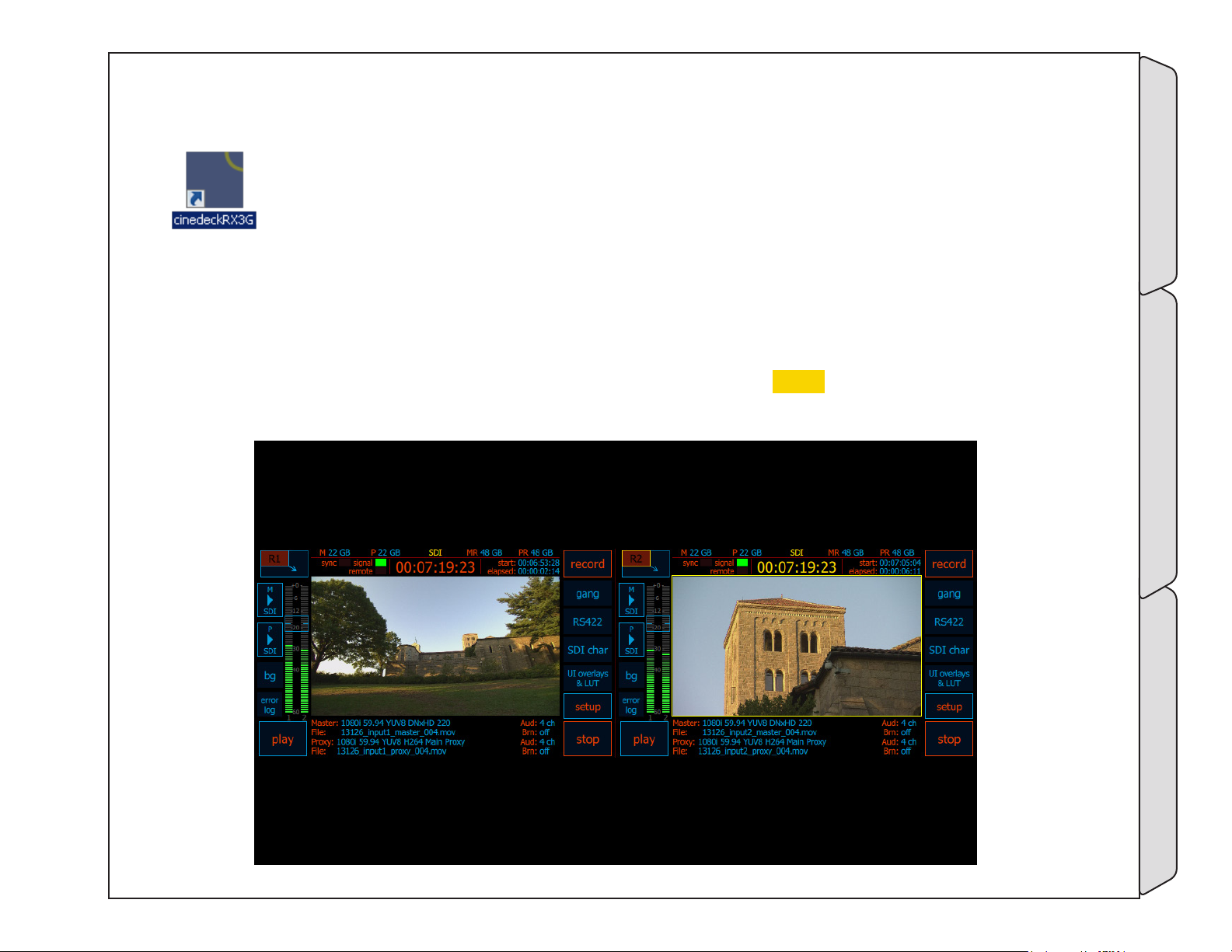
5.7 Multi view screen description
To start the Cinedeck from the desktop, locate and double click the Cinedeck short cut.
This will open the main, multi view screen with the channels in standby.
In standard SD/HD mode, there is one quadrant for each channel so depending on your Cinedeck model, there
will be two or four quadrants. Below is the dual channel view from a RX3G.
Surrounding each channel video preview, are multiple data areas for immediate access to the most important
details and buttons for accessing the most important functions. Note the yellow border around the right
channel which indicates it is the selected channel, the channel with the focus.
-Multi view screen description User Interface
Page - 87 of 297Cinedeck USER GUIDE - Cinedeck Version 4.5 13126 – June 15, 2015 - 19:21
Page 88
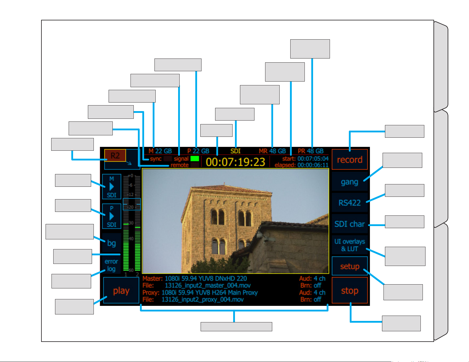
5.8 Multi view screen
112- remoTe
indiCaTor - (p.89)
111- single view
Toggle - (p.89)
135- m bUTTon
- (p.92)
134- p bUTTon
- (p.92)
133- baCKgroUnd (bg)
bUTTon - (p.91)
114- masTer spaCe/
Time - (p.89)
113- synC indiCaTor
- (p.89)
116- proXy spaCe/
Time - (p.89)
115- signal indiCaTor
- (p.89)
118- TimeCode
soUrCe - (p.89)
117- TimeCode
- (p.89)
121- redUndanT
proXy spaCe/Time -
(p.90)
120- sTarT &
elapsed Time -
(p.90)
119- redUndanT
masTer spaCe/Time
- (p.90)
122- reCord
bUTTon - (p.90)
123- gang
bUTTon - (p.90)
124- rs-422
bUTTon - (p.90)
125- sdi CHar
bUTTon - (p.90)
132- aUdio
meTers - (p.91)
131- error log
bUTTon - (p.91)
130- play bUTTon
- (p.91)
129- enCode overview - (p.91)
126- Ui overlays
& lUT bUTTon -
(p.91)
-Multi view screen User Interface
127- seTUp
bUTTon - (p.91)
128- sTop bUTTon
- (p.91)
Page - 88 of 297Cinedeck USER GUIDE - Cinedeck Version 4.5 13126 – June 15, 2015 - 19:21
Page 89
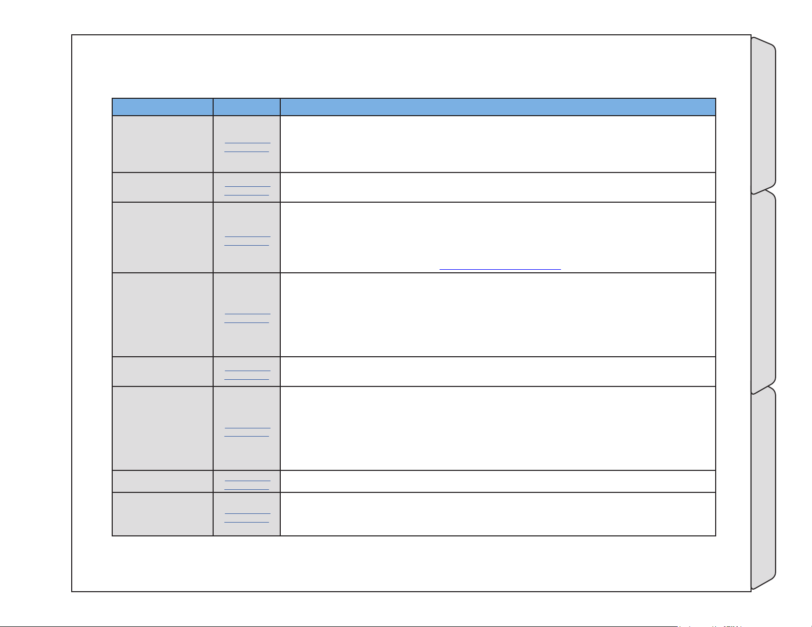
Multi view screen / - cont...
Name Location Description
The single view toggle, switches the user interface between multi view and single
111- single view
Toggle
112- remoTe
indiCaTor
113- synC indiCaTor
114- masTer spaCe/
Time
115- signal indiCaTor
116- proXy spaCe/
Time
117- TimeCode
118- TimeCode soUrCe
5.8 Multi view
screen - (p.88)
5.8 Multi view
screen - (p.88)
5.8 Multi view
screen - (p.88)
5.8 Multi view
screen - (p.88)
5.8 Multi view
screen - (p.88)
5.8 Multi view
screen - (p.88)
5.8 Multi view
screen - (p.88)
5.8 Multi view
screen - (p.88)
channel view. Additional information and tools such as waveform and vectorscope are
available in single channel view. Additionally, because of the increased screen space,
setting up on-screen overlays such as aspect ratio is easier in single view.
The remote indicator will light green when the associated channel detects a RS-422
connection.
The sync indicator will light green when an external a black-burst or tri-level sync
reference signal is detected.
The sync settings are available on the input page of the setup screen. For normal
operation, sync is set to auto. In auto mode, internal reference is used unless the
external signal is detected. See “273- sync” on page 140
In standby mode, master space/time displays the available space on the designated
destination drive.
When recording, the display will auto toggle between remaining space and
approximate remaining time, based on the selected encode bitrate. Note; the system
is unaware if other channels are being written to the same destination drive so the
available time estimate may need to be divided to accurately reflect remaining time.
The signal indicator will light green when the system detects and is set properly to
match an incoming signal.
In standby mode, proxy space/time displays the available space on the designated
destination drive.
When recording, the display will auto toggle between remaining space and
approximate remaining time, based on the selected encode bitrate. Note; the system
is unaware if other channels are being written to the same destination drive so the
available time estimate may need to be divided to accurately reflect remaining time.
The primary timecode display shows the current timecode which will be recorded.
Timecode source indicates where the timecode is coming from. Possible sources
include, SDI (serial digital embedded timecode), GEN (internal generated timecode,
LTC (linear timecode fro external source)
-Multi view screen User Interface
Page - 89 of 297Cinedeck USER GUIDE - Cinedeck Version 4.5 13126 – June 15, 2015 - 19:21
Page 90
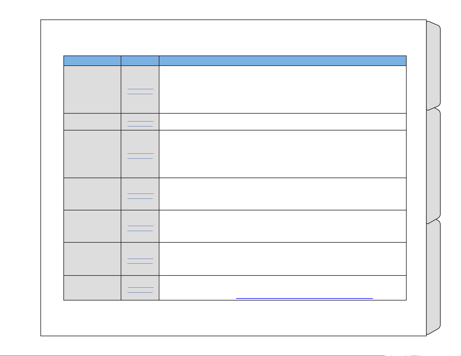
Multi view screen / - cont...
Name Location Description
In standby mode, redundant master space/time displays the available space on the
designated secondary destination drive.
119- redUndanT
masTer spaCe/Time
120- sTarT & elapsed
Time
121- redUndanT
proXy spaCe/Time
122- reCord bUTTon
123- gang bUTTon
124- rs-422 bUTTon
125- sdi CHar
bUTTon
5.8 Multi view
screen - (p.88)
5.8 Multi view
screen - (p.88)
5.8 Multi view
screen - (p.88)
5.8 Multi view
screen - (p.88)
5.8 Multi view
screen - (p.88)
5.8 Multi view
screen - (p.88)
5.8 Multi view
screen - (p.88)
When recording, the display will auto toggle between remaining space and
approximate remaining time, based on the selected encode bitrate. Note; the system
is unaware if other channels are being written to the same destination drive so the
available time estimate may need to be divided to accurately reflect remaining time.
Indicates the start timecode of the current recording and the elapsed time of the
current recording.
In standby mode, redundant proxy space/time displays the available space on the
designated secondary destination drive.
When recording, the display will auto toggle between remaining space and
approximate remaining time, based on the selected encode bitrate. Note; the system
is unaware if other channels are being written to the same destination drive so the
available time estimate may need to be divided to accurately reflect remaining time.
Activates recording.
• In Gang mode, recording will be triggered on multiple channels.
• In EDL record mode, this button will display and load the first EDL event.
• Depending on the mode, after recording starts, the button name can change.
Besides off, Gang record mode has two modes, normal which simultaneously triggers
all selected channels and staggered which triggers each selected channel separately
after a user defined time delay. This is primarily used when writing to spinning disc
systems to allow the drive heads time to recover between I/O requests.
RS-422 selects remote control modes between off, master, slave and VDCP slave.
RS-422 modes can be set independently for each channel.
• Select master mode to control a connected device from the Cinedeck.
• Slave and VDCP slave, allow external systems to control the selected channel.
SDI char toggles the character and information overlay output on and off for the user
interface video display and the SDI out. Setup opens a setup screen for customizing
the character output. (See “5.13 Character Out Customization” on page 110)
-Multi view screen User Interface
Page - 90 of 297Cinedeck USER GUIDE - Cinedeck Version 4.5 13126 – June 15, 2015 - 19:21
Page 91
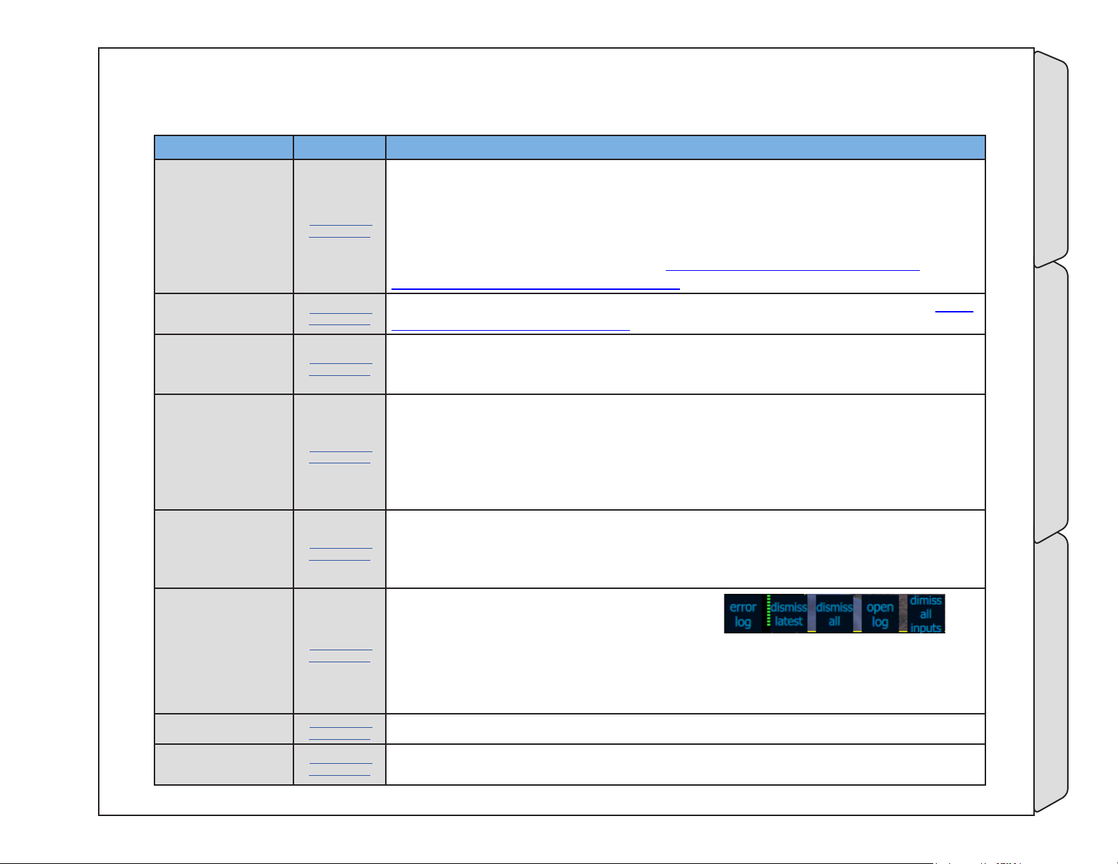
Multi view screen / - cont...
Name Location Description
UI overlays & LUT accesses on/off toggle and setup buttons for selecting an onscreen color LUT. LUT files can be loaded from any connected drive. When active,
126- Ui overlays & lUT bUTTon
127- seTUp bUTTon
128- sTop bUTTon
129- enCode
overview
130- play bUTTon
5.8 Multi view
screen - (p.88)
5.8 Multi view
screen - (p.88)
5.8 Multi view
screen - (p.88)
5.8 Multi view
screen - (p.88)
5.8 Multi view
screen - (p.88)
this preview LUT has no effect on recorded video. This control also accesses on/off
toggle buttons for on screen overlays; aspect ratio borders, aspect ratio letterbox
shading, safe area borders, grid/crosshairs. Setup for these on-screen overlays can be
accessed from single channel view. (See “111- Single view toggle” on page 89 and
“5.14 Overlay Customization” on page 111)
Setup takes you to the initial channel overview page and all setup screens. (See “5.16
Setup tabs explained” on page 113)
Pressing stop ends a current recording. Note that by default, stopping a recording
requires a long press of about 3 seconds which helps prevent accidental stops. If gang
is in use, all selected channels will stop.
When touched or clicked, the encode overview region shows one of three screens;
1. The default view displays current input, codec and file name settings for the
master and proxy with the number of audio channels and character burn status.
2. The second view displays the destination folder path and when recording, the
approximate encode data rate for the master and proxy are shown.
3. View three shows the current project and list names such as scene and sub scene.
The play button will load and play the most recently recorded clip. If nothing is in
the “last play” memory, pressing play will go directly to the clip manager. If a clip is
loaded for playback, the play button is renamed “open” and when pressed will open
the clip manager.
131- error log
bUTTon
132- aUdio meTers
133- baCKgroUnd (bg) bUTTon
5.8 Multi view
screen - (p.88)
5.8 Multi view
screen - (p.88)
5.8 Multi view
screen - (p.88)
Error log opens a sub-menu with controls for;
• dismissing the most recent warning for the selected channel
• dismissing all warnings for the selected channel
• opening the log of recent errors
• dismissing all errors on all channels
The audio meters reflect the average audio levels for the selected channel pair.
The bg button toggles a dark background on and off to better separate the on-screen
audio meters from the underlying video.
Page - 91 of 297Cinedeck USER GUIDE - Cinedeck Version 4.5 13126 – June 15, 2015 - 19:21
-Multi view screen User Interface
Page 92
Multi view screen / - cont...
Name Location Description
The P button toggles the on screen overlay of the proxy encode audio channels.
134- p bUTTon
135- m bUTTon
5.8 Multi view
screen - (p.88)
5.8 Multi view
screen - (p.88)
When this overlay is active it is possible to select a different channel pair for
monitoring. A long press opens the headphone monitor control screen (see “5.10
Headphone Monitor Controls” on page 98).
The M button toggles the on screen overlay of the master encode audio channels.
When this overlay is active it is possible to select a different channel pair for
monitoring. A long press opens the headphone monitor control screen (see “5.10
Headphone Monitor Controls” on page 98).
-Multi view screen User Interface
Page - 92 of 297Cinedeck USER GUIDE - Cinedeck Version 4.5 13126 – June 15, 2015 - 19:21
Page 93
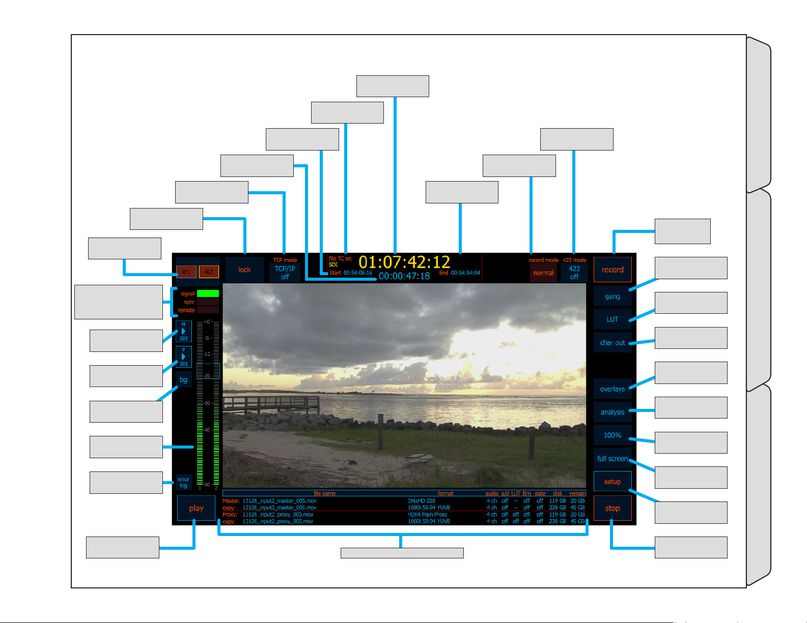
5.9 Single channel view
139- elapsed Time
- (p.94)
138- TCp remoTe -
(p.94)
137- loCK -
(p.94)
136- mUlTi view
Toggle - (p.94)
140- sTarT -
(p.94)
142- TimeCode -
(p.94)
141- file TC
soUrCe - (p.94)
145- 422 mode -
(p.94)
144- reCord mode
- (p.94)
143- end -
(p.94)
146- reCord -
(p.94)
147- gang -
(p.95)
165- signal - (p.97)
164- synC - (p.97)
163- remoTe - (p.97)
162- m - (p.97)
masTer meTers
161- p - (p.97)
proXy meTers
160- bg - (p.96)
baCKgroUnd
159- aUdio meTers
- (p.96)
158- error log -
(p.96)
157- play -
(p.96)
156- enCode overview - (p.96)
Single view screen
148- lUT -
(p.95)
149- CHar oUT -
(p.95)
150- overlays -
(p.95)
151- analysis -
(p.95)
152- 100% -
(p.95)
153- fUll sCreen -
(p.95)
154- seTUp -
(p.95)
155- sTop -
(p.96)
-Single channel view User Interface
Page - 93 of 297Cinedeck USER GUIDE - Cinedeck Version 4.5 13126 – June 15, 2015 - 19:21
Page 94
Single channel view / - cont...
Name Location Description
The multi view toggle, switches the user interface between single view and multi
136- mUlTi view
Toggle
137- loCK
138- TCp remoTe
139- elapsed Time
140- sTarT
141- file TC soUrCe
142- TimeCode
143- end
144- reCord mode
145- 422 mode
146- reCord
5.9 Single channel
view - (p.93)
5.9 Single channel
view - (p.93)
5.9 Single channel
view - (p.93)
5.9 Single channel
view - (p.93)
5.9 Single channel
view - (p.93)
5.9 Single channel
view - (p.93)
5.9 Single channel
view - (p.93)
5.9 Single channel
view - (p.93)
5.9 Single channel
view - (p.93)
5.9 Single channel
view - (p.93)
5.9 Single channel
view - (p.93)
channel view. Additional information and tools such as waveform and vectorscope are
available in single channel view. Additionally, because of the increased screen space,
setting up on-screen overlays such as aspect ratio is easier in single view.
Locks/Unlocks touch screen. Primarily for use in conjunction with MX tactile control
panel which provides direct access to other channels, whether locked or unlocked.
Future function.
Although not labeled, this timecode display indicates the elapsed time of the current
recording.
Indicates the start timecode of the current or most recent recording.
File TC source indicates where the timecode is coming from which will be written
to the file. Possible sources include, SDI (serial digital embedded timecode), GEN
(internal generated timecode, LTC (linear timecode fro external source)
The primary timecode display shows the current timecode which will be recorded.
Indicates the end timecode of the previous or most recent recording.
Selects between recording modes: (See “5.11 Record Modes” on page 99)
• “normal” - Used for standard recording
• “pause” mode - Ingest stops but the file is not closed.
• “pause & seek in file” Ingest stops, the file is not closed, an in-point can be set
• “insert baseband” - Allows inserting audio and video into a flat file.
RS-422 selects remote control modes between off, master, slave and VDCP slave.
RS-422 modes can be set independently for each channel.
• Select master mode to control a connected device from the Cinedeck.
• Slave and VDCP slave, allow external systems to control the selected channel.
Activates recording.
• In Gang mode, recording will be triggered on multiple channels.
• In EDL record mode, this button will display and load the first EDL event.
• Depending on the mode, after recording starts, the button name can change.
-Single channel view User Interface
Page - 94 of 297Cinedeck USER GUIDE - Cinedeck Version 4.5 13126 – June 15, 2015 - 19:21
Page 95
Single channel view / - cont...
Name Location Description
Besides off, Gang record mode has two modes, normal which simultaneously triggers
147- gang
148- lUT
149- CHar oUT
150- overlays
151- analysis
152- 100%
153- fUll sCreen
154- seTUp
5.9 Single channel
view - (p.93)
5.9 Single channel
view - (p.93)
5.9 Single channel
view - (p.93)
5.9 Single channel
view - (p.93)
5.9 Single channel
view - (p.93)
5.9 Single channel
view - (p.93)
5.9 Single channel
view - (p.93)
5.9 Single channel
view - (p.93)
all selected channels and staggered which triggers each selected channel separately
after a user defined time delay. This is primarily used when writing to spinning disc
systems to allow the drive heads time to recover between I/O requests.
LUT accesses on/off toggle and setup buttons for selecting an on-screen color LUT.
LUT files can be loaded from any connected drive. When active, this preview LUT has
no effect on recorded video.
Char out toggles the character and information overlay output on and off for the user
interface video display and the SDI out. A long press provides access to “setup” which
opens a setup screen for customizing the character output. (See “5.13 Character Out
Customization” on page 110)
The overlays button accesses on/off toggle buttons and settings for on screen
overlays; aspect ratio borders, aspect ratio letterbox shading, safe area borders, grids
and crosshairs. (See “5.14 Overlay Customization” on page 111)
The analysis button accesses on/off toggle buttons and settings for the on screen
video tools; waveform , vectorscope, histogram, clipping, edge detect and setup
for the clipping level. The waveform display can be switched between a 0-255
digital scale, -20-120 IRE scale and a 0%-100% percentage scale. The waveform and
histogram displays can be switched between Y - luminance, R - Red, G - Green, B Blue and full RGB parade modes. All of the scopes can be viewed as full screen or 1/4
screen overlay. (See “5.15 Video Analysis Tools” on page 112)
100% toggles the on screen video preview between full image and zoom mode.
Normally the entire image from the source is displayed however at just 1024 wide, the
Cinedeck on-board display is not a native HD panel. Zoom mode provides 4x image
magnification which allows more accurate visual analysis of image detail, focus, etc.
Full screen toggles between single channel view with controls around the perimeter
to a view which allows the preview video to take the entire display. The on-screen
controls switch to a momentary mode and fade out after a few seconds. Touching the
screen brings the controls into view again.
Setup takes you to the initial channel overview page and all setup screens. (See “5.16
Setup tabs explained” on page 113)
-Single channel view User Interface
Page - 95 of 297Cinedeck USER GUIDE - Cinedeck Version 4.5 13126 – June 15, 2015 - 19:21
Page 96
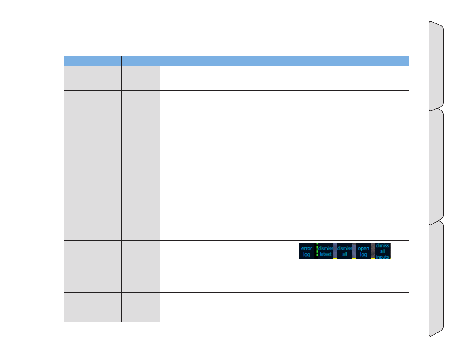
Single channel view / - cont...
Name Location Description
Pressing stop ends a current recording. Note that by default, stopping a recording
requires a long press of about 3 seconds which helps prevent accidental stops. If gang
is in use, all selected channels will stop.
Primarily, the encode overview region shows (from left to right) the current file name
settings for the master and proxy and if activated, the current file name settings
for the redundant (copy) master and proxy. The overview displays codec and input
settings for the master and proxy encodes and in several columns indicates:
• “audio” - The number of audio channels being recorded
• “a/d“ - If delay is active for one or more audio channels
• “LUT” - If a file is being recorded with a color LUT applied
• “Brn” - If a character burn is being applied to the video
• “slate” - If slate information is included in the clip
• “disk” - The size of the destination disc
• “remain” - The remaining space on the destination disc
• And when recording, the area between “slate” and “disk” opens up to reveal a data
rate display for each encode.
Additionally, when touched or clicked, the left region of the encode overview displays
the destination folder path for each file.
The play button will load and play the most recently recorded clip. If nothing is in
the “last play” memory, pressing play will go directly to the clip manager. If a clip is
loaded for playback, the play button is renamed “open” and when pressed will open
the clip manager.
155- sTop
156- enCode
overview
157- play
5.9 Single channel
view - (p.93)
5.9 Single channel
view - (p.93)
5.9 Single channel
view - (p.93)
158- error log
159- aUdio meTers
160- bg
5.9 Single channel
view - (p.93)
5.9 Single channel
view - (p.93)
5.9 Single channel
view - (p.93)
Error log opens a sub-menu with controls for;
• dismissing the most recent warning for the selected channel
• dismissing all warnings for the selected channel
• opening the log of recent errors
• dismissing all errors on all channels
The audio meters reflect the average audio levels for the selected channel pair.
The bg button toggles a dark background on and off to better separate the on-screen
audio meters from the underlying video.
Page - 96 of 297Cinedeck USER GUIDE - Cinedeck Version 4.5 13126 – June 15, 2015 - 19:21
-Single channel view User Interface
Page 97
Single channel view / - cont...
Name Location Description
The P button toggles the on screen overlay of the proxy encode audio channels.
161- p
162- m
163- remoTe
164- synC
165- signal
5.9 Single channel
view - (p.93)
5.9 Single channel
view - (p.93)
5.9 Single channel
view - (p.93)
5.9 Single channel
view - (p.93)
5.9 Single channel
view - (p.93)
When this overlay is active it is possible to select a different channel pair for
monitoring. A long press opens the headphone monitor control screen (see “5.10
Headphone Monitor Controls” on page 98).
The M button toggles the on screen overlay of the master encode audio channels.
When this overlay is active it is possible to select a different channel pair for
monitoring. A long press opens the headphone monitor control screen (see “5.10
Headphone Monitor Controls” on page 98).
The remote indicator will light green when the associated channel detects a RS-422
connection.
The sync indicator will light green when an external a black-burst or tri-level sync
reference signal is detected.
The sync settings are available on the input page of the setup screen. For normal
operation, sync is set to auto. In auto mode, internal reference is used unless the
external signal is detected.
See “273- sync” on page 140
The signal indicator will light green when the system detects and is set properly to
match an incoming signal.
-Single channel view User Interface
Page - 97 of 297Cinedeck USER GUIDE - Cinedeck Version 4.5 13126 – June 15, 2015 - 19:21
Page 98
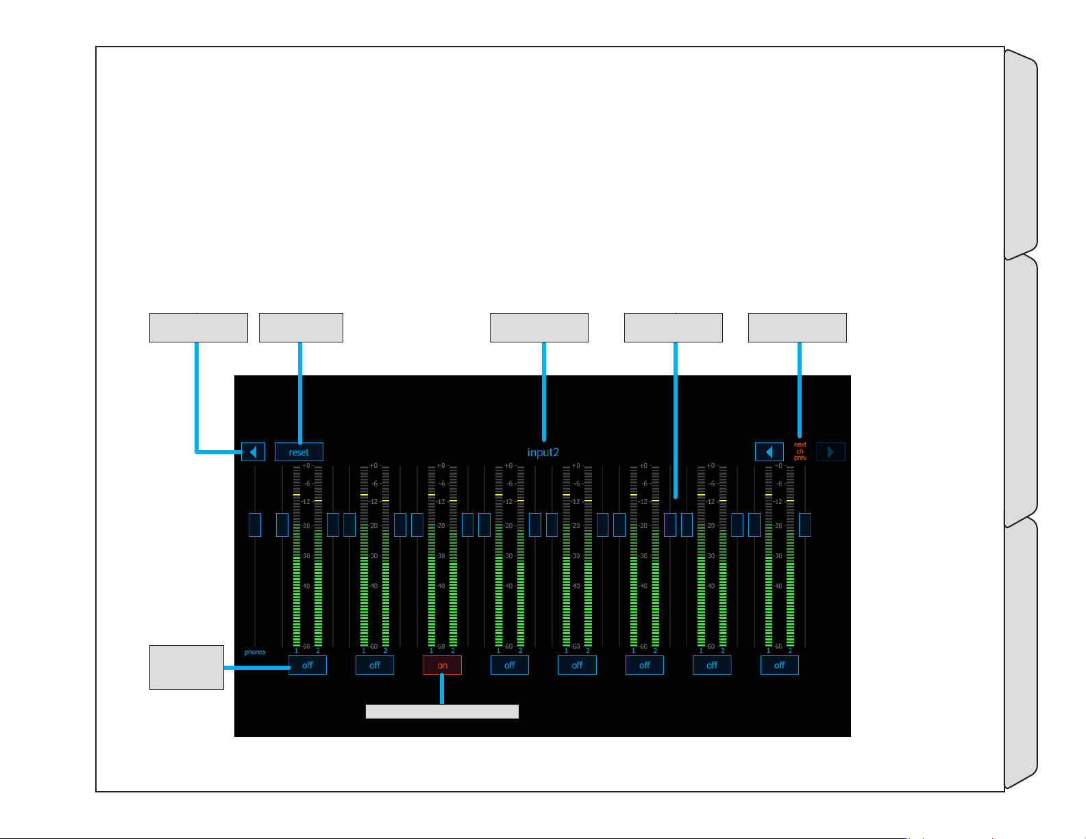
5.10 Headphone Monitor Controls
The headphone monitor control panel is used to select the channel pair being monitored and adjust left and
right audio levels.
Close bUTTon CHannel idenTifier
CHannel pair
seleCTor
bUTTons
reseT all faders
To UniTy
seleCTed CHannel is HigHligHTed
adjUsTable CHannel
faders
neXT <> previoUs
CHannel seleCTor
-Headphone Monitor Controls User Interface
Page - 98 of 297Cinedeck USER GUIDE - Cinedeck Version 4.5 13126 – June 15, 2015 - 19:21
Page 99
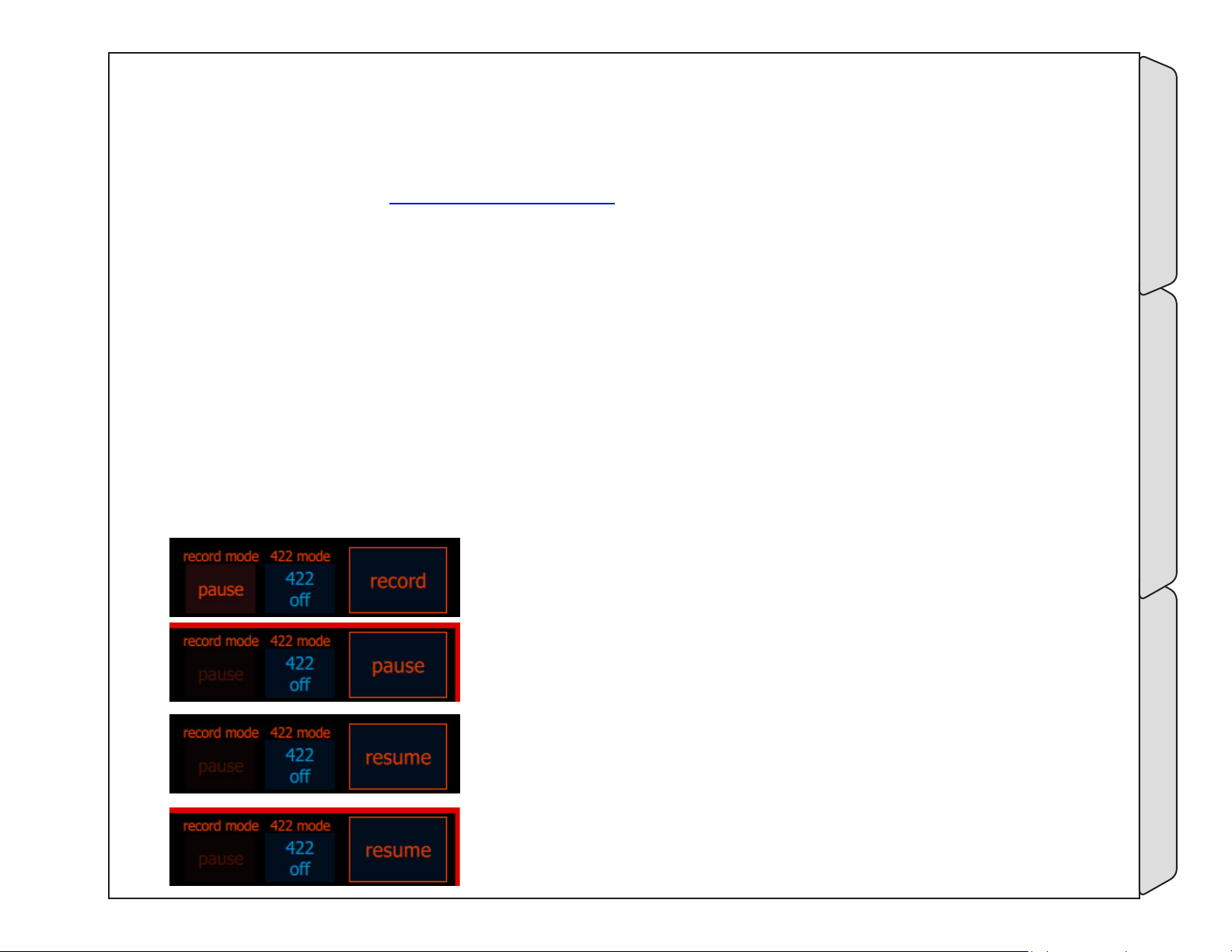
5.11 Record Modes
Record mode selects between the different recording capabilities such as pause and insert, which should not be confused
with “UI mode” which selects between formats and different basic I/O settings such as HD and 4K. For additional
information on UI mode, see “5.25.1 UI mode” on page 185
• “normal” - Used for standard recording
• “pause” mode - Ingest stops but the file is not closed.
• “pause & seek in file” Ingest stops, the file is not closed, an in-point can be set
• “insert baseband” - Allows inserting audio and video into a flat file.
5.11.1 Normal
Normal record mode is used for typical single and multi-channel recording and playback tasks.
5.11.2 Pause
Pause record mode is used in situations where a long recording session will be broken up by periods where
no useful action is occurring. Typically in such situations, recording will be stopped but each normal stop start
generates a new file which is sometimes undesirable. When in pause mode, the record button changes to
“pause” and the system functions much like a traditional analog tape recorder.
In pause mode, before initial recording starts, the record button is in its
normal condition.
After recording starts, the record button changes to a “pause” button.
When “pause” is pressed, ingest is halted, the file remains in an open but
static state and the record/pause button changes name to “resume”.
When in resume, the record (red border) indicator will blink on and off,
indicating that record mode is still active but ingest has been paused.
Page - 99 of 297Cinedeck USER GUIDE - Cinedeck Version 4.5 13126 – June 15, 2015 - 19:21
NormalRecord Modes User Interface
Page 100

Record Modes / Pause cont...
It is also important to understand that when “pause” is active, it is active for all channels associated to the selected
project. Also, “pause” can be used in conjunction with gang mode so you can control multiple channels in pause mode
simultaneously.
paUse reCord aCTive and
paUsed for Two CHannels
PauseRecord Modes User Interface
Page - 100 of 297Cinedeck USER GUIDE - Cinedeck Version 4.5 13126 – June 15, 2015 - 19:21
 Loading...