

Page 1
Page 2

MF GROUP S.p.A. - CIM Division
Via Serra, 2 - Calderara di Reno
40012 BOLOGNA - Italy
Tel +39 051 6465011 Fax +39 051 6465012 www.cimitaly.it
© Copyright 2008 All rights reserved
Reproduction, Modification, complete or partial
translation of this manual is strictly forbidden
without prior written approval of CIM SpA.
IMPORTANT: CIM SpA cannot be held responsable
for any errors or damages caused by the use of
supplies or spare parts not specifically approved
or garanteed by CIM SpA.
METAL DOT MATRIX SERIES is a registred trade mark by CIM SpA
Page 3

INDEX I
REV. 05-2008
FOREWORD.................................................... 0.5
0
0.1USING THE WORKSHOP MANUAL............. 0.7
0.1.1 Importance of the manual ....... 0.7
0.1.2 Conserving the manual............. 0.7
0.1.3 Consultation the manual .......... 0.7
0.1.4 Symbols used in the manual ..... 0.7
0.2 PROCEDURE FOR UPDATING MANUAL IN
CASE OF MODIFICATIONS TO
MACHINE ................................................ 0.8
0.3 ORDERING ORIGINAL REPLACEMENT
PARTS ..................................................... 0.8
GENERAL INFORMATION .............................. 1.9
1
1.0 GENERAL INFORMATION ..................... 1.10
1.1 ELECTRICAL SPECIFICATION ............... 1.11
1.2 EQUIPMENT CLASSIFICATION AND
STANDARD REFERENCE ....................... 1.11
1.3 PHYSICAL ENVIRONMENT AND
OPERATING CONDITIONS ................... 1.11
1.4 DIMENSIONS AND WEIGHT .................. 1.11
1.5 STAMPING CAPACITY AND TECHNICAL
FEATURES ............................................... 1.12
1.6 CAUTIONS............................................. 1.13
1.7 ENVIRONMENTAL
RECOMMENDATIONS .......................... 1.14
1.8 SAFETY INSTRUCTIONS ......................... 1.15
1.9 DECLARATIONS OF CONFORMITY ...... 1.17
1.10 DIRECTIVE WEEE ................................... 1.18
UNPACKING .................................................2.19
2
2.0 UNPACKING ......................................... 2.20
INSTALLATION ...............................................3.21
3
3.1 CHECKING THE ACCESSORIES ............ 3.22
3.2 ELECTRICAL CONNECTIONS ............... 3.23
3.3 CHOOSING THE WORKING PLACE ..... 3.23
3.4 ADVISE AND CARE DURING THE
INSTALLATION ....................................... 3.24
3.5 SWITCHING ON AND CONTROLLING THE
DISPLAY ................................................. 3.25
OVERALL DESCRIPTION................................4.27
4
4.1 OVERALL PARTS DESCRIPTIONS .......... 4.28
4.1.1 The top door............................. 4.28
4.1.2 Safety mushroom pushbutton
(emergency stop) .................... 4.28
4.1.3 The console............................... 4.29
4.1.4 The indicator lamps ................. 4.29
4.2 DIFFERENCES BETWEEN MANUAL (1000)
AND AUTOMATIC (2000) MODELS...... 4.30
4.3 STORED CONFIGURATION AND
REPLACING LITHIUM BATTERY ............. 4.31
HOW TO PRODUCE ONE CARD ...................5.33
5
5.0 HOW TO PRODUCE ONE CARD ......... 5.34
5.1 SETTING THE MACHINE ........................ 5.34
5.1.1 Automatic (2000) version ........ 5.35
5.1.2 Manual (1000) version ............. 5.36
5.1.3 Stylus adjustment ...................... 5.37
5.2 SWICHING ON THE MACHINE ............. 5.38
5.3 INSTALL THE SOFTWARE "SWORD" ........ 5.39
5.4 RUN THE PROGRAM AND PRODUCE ONE
CARD ................................................... 5.40
MAINTENANCE.............................................6.43
6
6.1 SCHEDULED LUBRICATION .................. 6.44
6.2 RECOMMENDED LUBRICANTS ............ 6.44
6.3 GENERAL MAINTENANCE BY THE
OPERATOR ............................................ 6.45
6.3.1 Trolley-Truck Oiling ................... 6.45
6.3.2 Plate loader oiling ................... 6.45
6.3.3 Stamping unit ............................ 6.46
6.4 UNLOADER LIFTER ................................ 6.46
6.5 SAFETY INTERLOCK SWITCH
FUNCTIONAL TEST ................................ 6.46
TROUBLE SHOOTING.....................................7.47
7
7.1 ERROR MESSAGES AND PROBLEM
SOLVING................................................ 7.48
THE MACHINE'S SETUP ................................. A.51
A
A.0 SETUP PROCEDURE ............................. A.52
A.1 KEYBOARD DESCRIPTION ................... A.52
A.2 DESCRIPTION AND MODIFY OF
SETTING ................................................ A.54
A.3 GENERAL PROGRAMMING OF THE
MACHINE ............................................. A.56
A.4 CONFIGURATION PARAMETERS ......... A.58
A.5 SERIAL PORT PROGRAMMING ........... A.59
A.6 MECHANICAL PARAMETERS
ADJUSTMENT ....................................... A.60
A.7 PROTOCOLS SETTINGS ........................ A.61
A.8 PASSWORD .......................................... A.65
A.9 STAMPING CONFIGURATION ............. A.66
A.10KEYPAD LCD SETTING ......................... A.68
A.11RESET OF PARAMETERS ....................... A.70
A.12DISPLAYING THE COUNTERS ............... A.71
A.13CARD TEST LIST .................................... A.72
A.14RESET OF THE MACHINE ..................... A.72
HOW TO UPDATE THE FW ............................. B.73
B
B.1 INTRODUCTION .................................... B.74
B.2 CONNECTION PROCEDURE ............... B.74
B.3 SOFTWARE ............................................. B.75
B.4 FIRMWARE UPDATING PROCEDURE ... B.76
B.5 CHANGE RESIDENT LOGOS AND FONT
PROCEDURE ......................................... B.76
LCD EDIT ..................................................C.78
CC
C.1 LCD EDIT AVAILABILITY ........................ C.78
C.2 ENABLING THE OFF-LINE MODE ......... C.78
C.3 FORMAT MENU .................................... C.79
C.4 FORMAT CHANGE .............................. C.79
C.5 STAMP DATA ENTRY ............................ C.80
C.6 EDIT STAMPED CARDS ........................ C.82
C.7 FORMATS - GENERAL .......................... C.83
C.8 SETTING UP A FORMAT ....................... C.87
C.9 DESIGNING INDIVIDUAL FIELDS .......... C.92
C.10STORING THE FORMAT ........................ C.97
METAL DOT MATRIX
REV. 04.2002
OPERATORS MANUAL
i-3
Page 4

I INDEX
REV. 05-2008
This page is left empty
due to editing reason
i-4 METAL DOT MATRIXREV. 04.2002
OPERATORS MANUAL
Page 5
METAL DOT MATRIX
FOREWORD
0
0-5
Page 6

0 FOREWORD
REV. 05-2008
0-6 METAL DOT MATRIXREV. 04.2002
OPERATORS MANUAL
Page 7
FOREWORD 0
REV. 05-2008
0.1 USING THE WORKSHOP MANUAL
0.1.1 Importance of the manual
This manual contains the instruction for putting
into service, using and maintainance of the METAL
DOT MATRIX SERIES, AUTOMATIC (METAL DOT
MATRIX 2000) and MANUAL (METAL DOT MATRIX
1000) .
Before to install and put into service the machine
we recommend that you carefoully read all the
instructions in this manual, with particular reference
to chapters1,2 and 3, as the effectiveness of any
servicing operation depends on the correct and
methodical application of the information
contained herein.
If you run into difficulties or setbacks,
SERVICE DEPARTMENT will be happy to provide
you with the necessary advice and assistance.
CIM S.p.A. declines any liability for any injury or
damage resulting from incorrect or unsuitable
operations.
CIM S.p.A. reserves the right to make any
modifications aimed at improving its products
without prior notification.
Please ensure that any amendments or updates
you may receive are kept with the original version
of this manual.
CIM S.p.A.
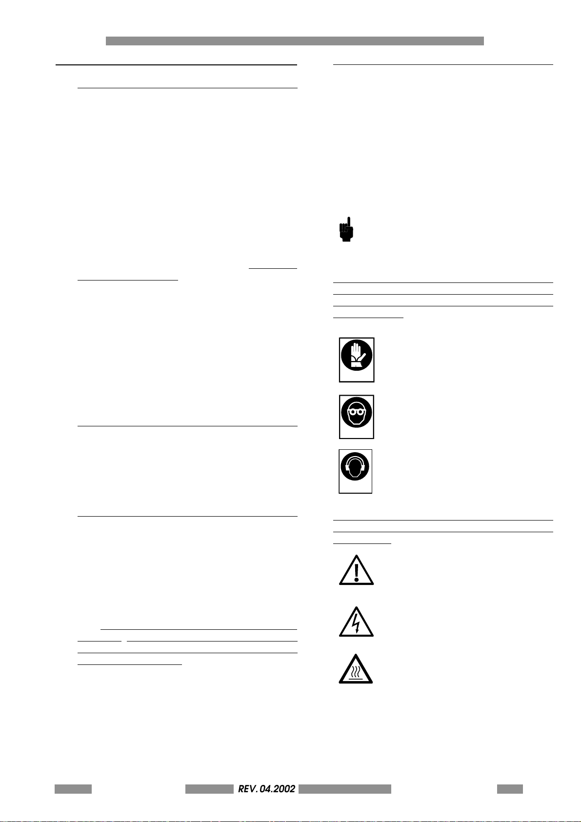
0.1.4 Symbols used in the manual
The Safety symbols and notices shown below are
used throughout this manual to draw the readers
attention to the hazards associated with particular
procedures and operations which could result in
damage to the machines or personal injury, or to
indicate good working practices.
Th e s am e w ar n i ng s i mb o l s a r e al s o pl a c ed o n th e
machine to indicate dangerous areas.
MEANING OF THE SYMBOLS
GENERAL OPERATIONAL NOTE
PAY ATTENTION TO THE SYMBOLS
AND TO THE INSTRUCTIONS IN THE
ADJACENT TEXT.
Safety notices (rectangular): you must use the
protection shown in the notices when carrying
out the operation in question to avoid risk of
personal injury:
PROTECT YOUR HANDS (WEAR
GLOVES)
PROTECT YOUR EYES (WEAR SAFETY
GOGGLES)
0.1.2 Conserving the manual
Do not tear or remove pages from the manual, or
overwrite any parts of the manual for any reason.
Keep the manual in safe place protected from
excess heat and humidity.
0.1.3 Consultation the manual
This manual comprises:
COVER PAGE IDENTIFYING THE TYPE OF
PRODUCT
TABLE OF CONTENTS
INSTRUCTIONS AND/OR NOTES ON THE
PRODUCT
The INSTRUCTIONS AND/OR NOTES ON THE
PRODUCT define the safe working practices,
correct procedures and skills required to service
the machine correctly.
Please note that some of the illustrations in the
manual, which are included to help you identify
the parts described in the text, show standard
engines and therefore may differ in some details
with respects to the product in your possession.
PROTECT YOUR HEARING (HEAD
PHONES)
S0000020
Danger warning signs (triangular): General
warning of risk of personal injury or damage to
the product:
CAUTION ! GENERAL DANGER.
CAUTION ! HIGH TENSION.
CAUTION ! HIGH TEMPERATURE
HAZARD
S00000104
METAL DOT MATRIX
REV. 04.2002
OPERATORS MANUAL
0-7
Page 8
0 FOREWORD
REV. 05-2008
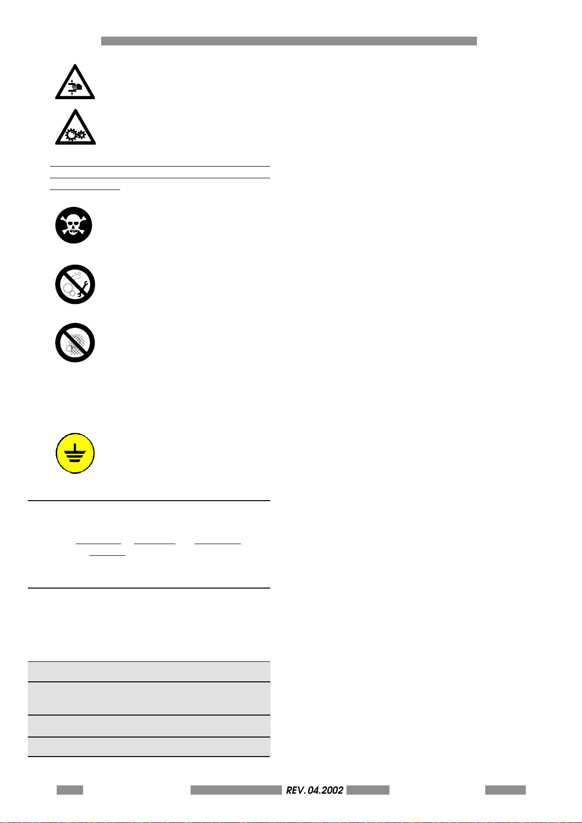
CAUTION! RISK OF CRUSHING.
CAUTION! MOVING MACHINE
COMPONENTS.
Prohibition notices (circular) denoting operations
which are expressly prohibited to avoid risk of
personal injury.
THE OPERATION INDICATED IN THE
TEXT IS STRICTLY PROHIBITED
S0000003
IT IS STRICTLY PROHIBITED TO
CARRY OUT MAINTENANCE WORK
IN THE PRESENCE OF MOVING
PARTS.
S0000074
IT IS STRICTLY FORBIDDEN TO
REMOVE THE SAFETY
PROTECTION. THESE SAFETY
GUARDS SHOULD BE REMOVED
ONLY BY SPECIALISED AND
AUTHORISED TECHNICAL
PERSONS WHO HAVE TAKEN CARE
TO ADOPT ALL SECURITY
MEASURES TO AVOID ANY RISK OF
DANGER AND INJURY.
EARTHED CABLES
THIS SYMBOL INDICATES GROUND
REFERENCE POINT.
0.2 PROCEDURE FOR UPDATING MANUAL IN CASE OF
MODIFICATIONS TO MACHINE
I f t he MACHINE or MANUAL are MODIFIED in any
way, an UPDATE will be sent for insertion into the
Manual.
0.3 ORDERING ORIGINAL REPLACEMENT PARTS
To help us provide a fast and efficient service,
always specify the following information when
ordering replacement parts:
- METAL DOT MATRIX type as indicated on nameplate;
- Serial number as indicated on nameplate and
stamped on crankcase;
- Quantity of each item required.
- Code of required part.
0-8 METAL DOT MATRIXREV. 04.2002
OPERATORS MANUAL
Page 9
METAL DOT MATRIX
GENERAL INFORMATION 1
1-9
Page 10

1 GENERAL INFORMATION
REV. 05-2008
1.0 GENERAL INFORMATION
METAL DOT MATRIX i s a n a u t o m a t i c f e e d e r ( METAL
DOT MATRIX 2000) and manual feeder (METAL
DOT MATRIX 1000) stamper unit which use and
new punch technology to stamp special
characters, symbols and also logos on a variety
of metal plates, including stainless steel,
aluminium, copper and brass (see chap. 1.5 for
more details). The various functions are controlled
by a microprocessor which manages the internal
counters and the storing of data such as formats
and texts in an on board CMOS memory. A small
backup battery supplies the charge for the
memory thus permitting all information to be
saved and ready for subsequent use even if the
machine has been switched off.
The METAL DOT MATRIX system consists in an
stamper unit driven by a Personal Computer (not
supplied) by means of the dedicated CIM
software named SWORD.
The system may also run in offline mode, without
software, to facilitate setting operations.
OPERATOR MODE (ON LINE)
With the on line standard mode the stampings
commands are transmitted by Host Computer
with the serial interface RS232 using CIM, XON/
XOFF, STORED or MULTIEMBOSSER protocols. The
layout is defined on the Host Computer with the
Software supplied with the equipment (SWORD).
Refers to chap. 5 and SW user's manual for details
about using of the SW.
SETTING MODE (OFF-LINE)
The off line mode is intended for testing and
setting purpose only in order to semplify settings
and advanced operations (for expert operators
or technical)
With this modality commands are transmitted by
means of a keyboard connect to the rear panel
DIN connector. This modality permits to expert
operators to modify the setup parameters of the
machine (Annex A) and to make pre-defined
jobs (CARD TEST) in order to verify the correctness
of settings and the functionality. Refers to Annex
A for details.
1-10 METAL DOT MATRIXREV. 04.2002
OPERATORS MANUAL
UPGRADE FIRMWARE
A service port placed on the rear panel permits
by few simply operations to upgrade the FW of
the machine in each moment. Refers to Annex B
to see how to upgrade the firmware.
Page 11
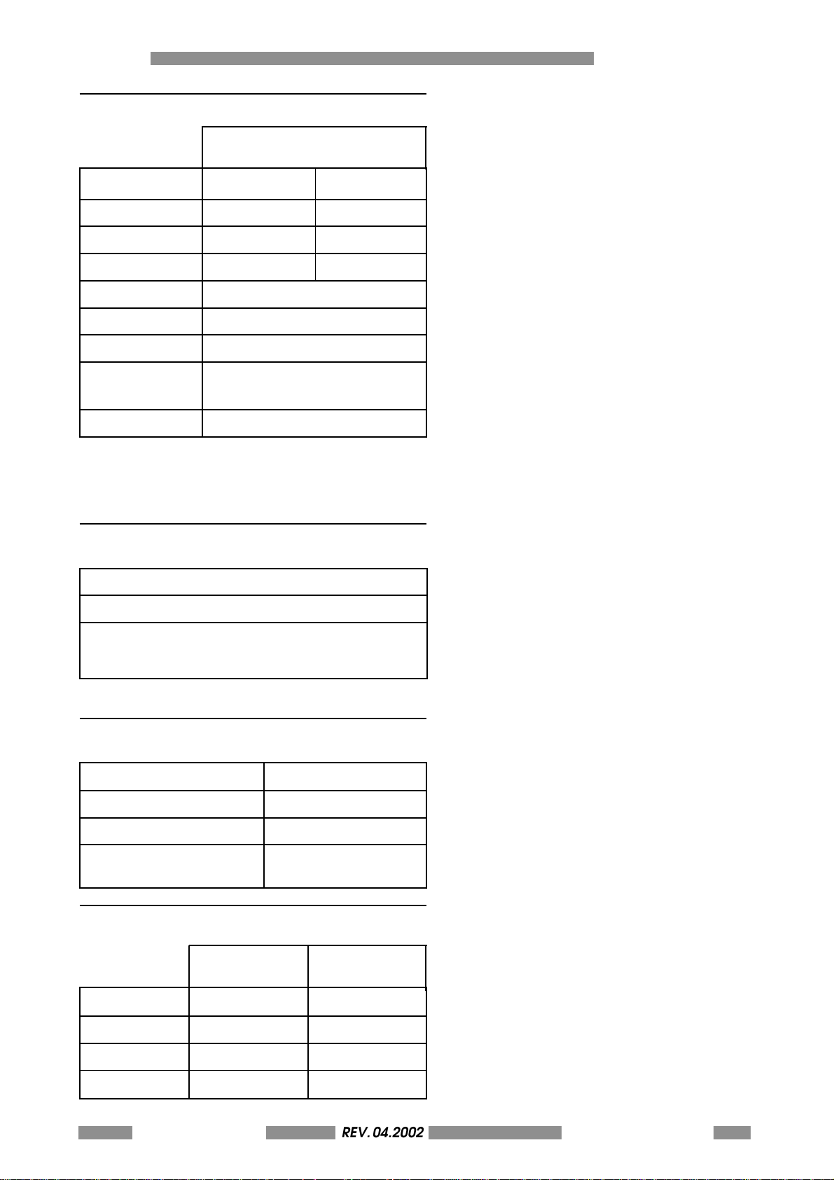
1.1 ELECTRICAL SPECIFICATION
REV. 05-2008
METAL DOT MATRIX
1000 and 2000
Power Supply 117V 60Hz 230V 50Hz
Power Absorbed 900 W 600 W
Current max 1 A 1 A
Fuses (2) 5x20 mm T 2,5 A T 2,5 A
Logic Micropr. a 8 bit
Backup Power Lithium Battery 3.6 V
PC Interface RS 232 Asinc. Progr.
Baud Rate Progammable (Default
9600 Baud)
Working Noise (*) Lower than 75 dB (A)
(*) Mesured during normal working use at a
distance of 1 m from the surface of the machinery
and at a height of 1,60 m from the floor.
GENERAL INFORMATION 1
1.2 EQUIPMENT CLASSIFICATION AND STANDARD REFERENCE
Installation category II
IP Protection IP 20
Standard reference IEC EN 50081-1
IEC EN 50082-2
IEC EN 60950 ed. 4th
1.3 PHYSICAL ENVIRONMENT AND OPERATING CONDITIONS
Operating Temperature +5°C ÷ +40°C
Operating Humidity 30% ÷ 90%
Operating altitude 1000 m
Transportation and -25°C ÷ 55°C
storage temperature
1.4 DIMENSIONS AND WEIGHT
METAL DOT
MATRIX 2000
Height 385 mm 385 mm
Width 625 mm 625 mm
Depth 745 mm 745 mm
Weight 57 Kg 54 kg
METAL DOT MATRIX
METAL DOT
MATRIX 1000
REV. 04.2002
OPERATORS MANUAL
1-11
Page 12
1 GENERAL INFORMATION
REV. 05-2008
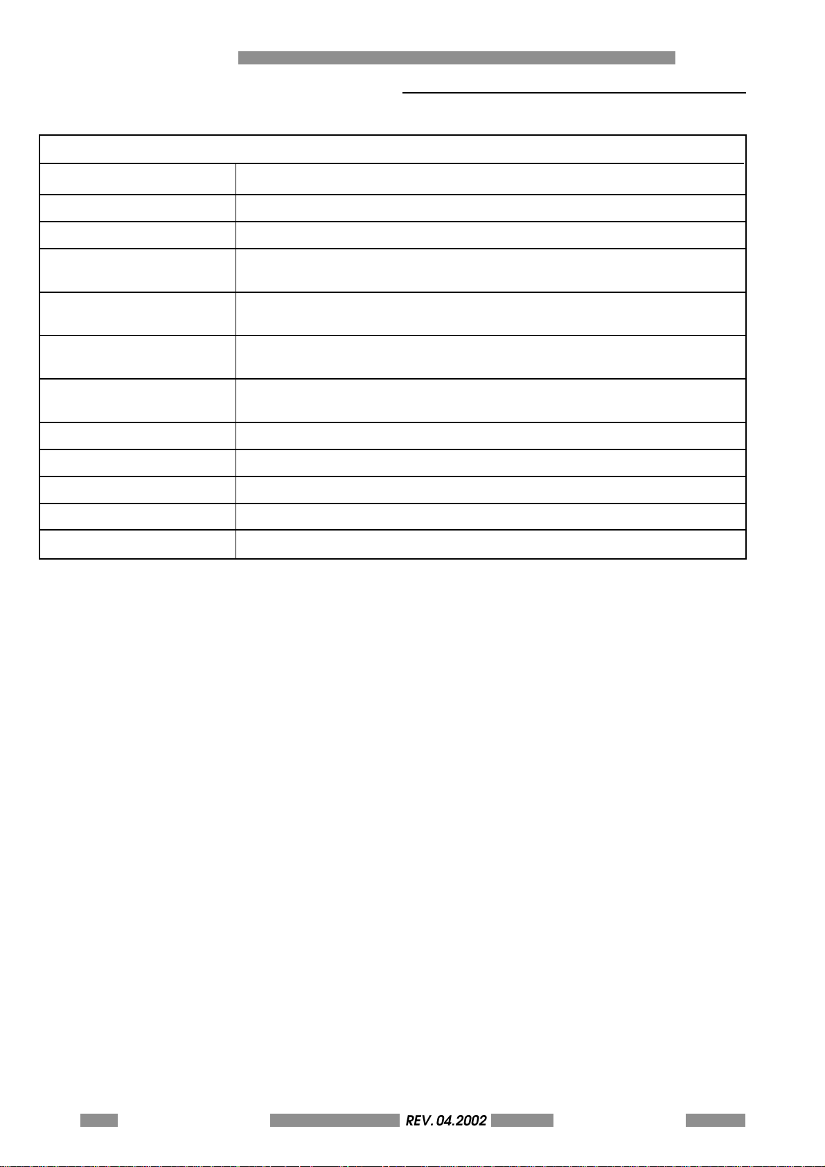
1.5 STAMPING CAPACITY AND TECHNICAL FEATURES
MDM1000/MDM2000
PERFORMANCE Depending on font and size (e.g.: ht 6 mm = 1 character/4 seconds)
MARKETING SPEED About 50 dots per second
DOT DENSITY 200 DPI
MARKETING FORCE 50 Kg
IN KILOGRAMS
INPUT HOPPER CAPACITY MDM1000: manual feeding
MDM2000: 250 plates (0,4 mm) variable dimensions
OUTPUT HOPPER CAPACITY MDM1000: manual feeding
MDM2000: side eject or FIFO elevator (250 plates)
STAMPING AREA Full plate except 1 mm from the top and left/right edges and 7 mm from the
bottom edge. Avoid the edges in order to not damage the stylus
STAMPING PRESSURE Adjustable depending on material stamped (see chap. 5.1.3)
FONTS Standard Windows fonts including special characters and symbols
LOGOS Up to 2 at a time, resident in equipment (see Annex B)
LOGO DIMENSIONS Max area about 84 cm²
STYLUS Widia
1-12 METAL DOT MATRIXREV. 04.2002
OPERATORS MANUAL
Page 13

1.6 CAUTIONS
REV. 05-2008
WARNING!: THE MACHINE IS INTENDED NOT FOR
CONTINUOUS USE (MAX 8-9 HOURS/DAY).
WARNING (FOR 117 VAC APPLICATIONS ONLY):
This is a "CLASS A" equipment. In a domestic
environment this product may cause radio
interference in wich case the user may be required
to take adeguate measures.
Certain industrial envirament charaterized by
the presence of high level transient overvoltage
(> 500 V) on the serial transmission, may cause
malfunctioning to the system PC machine. In this
case we suggest to use the overvoltage suppressor
(supplied with the machine) to protect the serial
line communication.
If the daily personal exposure of the operator to
noise is likely to exceed 85db the operator must
wear some form of efficient ear protection, in
accordance with the 86/188/EEC standards.
GENERAL INFORMATION 1
METAL DOT MATRIX
REV. 04.2002
OPERATORS MANUAL
1-13
Page 14
1 GENERAL INFORMATION
S0000020
REV. 05-2008
1.7 ENVIRONMENTAL RECOMMENDATIONS
The machine should work in a closed room
protected from dust and excessive humidity. The
machine should be positioned in such a way that
its distance from the walls, doors, windows, other
machines or working positions garantees
immediate access in the case of urgency,
maintenance or reparation.
DO NOT INSTALL THIS MACHINE IN THE
NEIGHBOURHOOD OF OTHER
OPERATING MACHINES WHICH
PRODUCE DUST SINCE DUST CAN
DEPOSIT ITSELF INSIDE THE MACHINE
AND CAUSE DAMAGE TO THE
INTERNAL ELECTRIC DEVICES.
LIQUID SHOULD NOT BE PLACED ON
THE MACHINE COVER SINCE IT HAS
NOT BEEN WATER SEALED.IT IS
PARTICULARY IMPORTANT TO AVOID
OXIDATION WHICH WOULD ADDTO THE
WEAR AND EROSION OF THE
MECHANICAL PARTS.
The machine has been made with fire proof
materials thus diminishing the risk of general fire.
Short circuit protection has been implemented so
that the power supply is immediately isolated
thus avoiding unwanted current absorption from
the external power line.
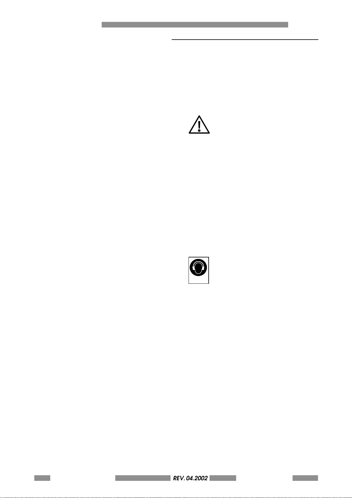
THE MACHINE GENERATES A
WORKING NOISE LEVEL LESSER THAN
75DB (MEASURED AT A DISTANCE OF
ONE METER AND AT THE HEIGHT OF
1.60 M FROM THE GROUND).
WORKING WITH CERTAIN TYPES OF
STEEL PLATES OR WITH THE MACHINE
PLACED ON A SUPPORT TABLE WHICH
AMPLIFIES AIRBORNE NOISE OR WITH
CARELESS MECHANICAL SETTING
(SEE CHAP. 5.1.3), THIS VALUE MAY BE
EXCEEDED. IF THE DAILY PERSONAL
EXPOSURE OF THE OPERATOR TO
NOISE IS LIKELY TO EXCEED 85DB THE
OPERATOR MUST WEAR SOME FORM
OF EFFICIENT EAR
PROTECTION, IN ACCORDANCE WITH
THE 86/188/CEE STANDARDS.
1-14 METAL DOT MATRIXREV. 04.2002
OPERATORS MANUAL
Page 15
1.8 SAFETY INSTRUCTIONS
REV. 05-2008
With "Operator Area" is intended the
area that is accessible, during normal
u s e , w i t h ou t t h e u s e of a t o o l o r th a t t h e
means of access is deliberately provided
to the operator. Operator Area is also
the area to which the Operator is instructed to
enter regardless of whether or not tools are
needed to gain access.
The Operator Area of New Metal is compliant
with all the safety requirements of the main
european and extra-european Standards.
However we would recommend to read carefully
the following pages. These instructions recall the
warning symbols used in the Operator Area of
the machine and show any possible dangerous
situation with the precaution that you have to
adopt.
Dangerous mechanical parts (straps,
pulley, gripper to move the card) - Risk
of crushing or entrapment.
Pay attention in introducing hands in
processing card areas. Pay attention to the
entrapment risks for your hair.
The machine is provided of mechanical
protections (enclosures, shields or guards) and
software protection systems to block any moving
part when top cover is open and dangerous part
become accessibles. Nevertheless, in case of
damage of the safety systems, the machine can
run also with the cover opened. In this case
mechanical moving parts represents a possible
danger for the safety of the Operator.
In case of demage of safety systems please,
switch off the machine and call the service.
Warning: the machine may be driven also by
remote control (Personal Computer). Pay
maximum attention during access in dangerous
areas (removal of blocked cards, errors restore or
ordinary maintenance).
In case of necessity a safety mushroom
pushbutton placed on the front panel permits an
immediate arrest of the machine (see 4.1.2. for
details).
GENERAL INFORMATION 1
High voltage parts - Risk of electric
shock.
No high voltage parts are accessible
into the Operator Area. All the high voltage
circuits are contained into closed areas and are
protected by fixed enclosures. To maximize the
safety, covers and any metal accessible part are
electrically connected to ground. The efficiency
of the connection is tested on every sample by
the internal quality check before putting the
product on the market.
METAL DOT MATRIX
REV. 04.2002
OPERATORS MANUAL
1-15
Page 16
1 GENERAL INFORMATION
REV. 05-2008
Do not remove or modify in any circumstances
the enclosures and the internal protections. In
case of necessity referes to the CIM Technical
Service.
THE MACHINE IS FURNISHED WITH
SPECIAL SAFETY GUARDS WHICH
PROTECT THE OPERATOR FROM
COMING INTO CONTACT WITH THE
MECHANICAL AND ELECTRICAL
PARTS INSIDE THE MACHINE. ONLY
THOSE PERSONS WHO ARE
SPECIALISED IN REPAIRS AND
MAINTENANCE AND WHO HAVE BEEN
AUTHORISED SHOULD HAVE ACCESS
TO THE ABOVE MENTIONED PARTS.
SIMPLE GENERAL MAINTENANCE CAN
BE SAFELY PERFORMED BY THE
OPERATOR SO LONG AS THE MACHINE
HAS BEEN STOPPED AND THE
ELECTRICAL POWER SUPPLY HAS
BEEN DISCONNECTED.
CIM S.p.A. cannot be held responsible for the
consequences of not abinding by these principles
when using the machine. In case of breadown
please call the technical assistance.
1-16 METAL DOT MATRIXREV. 04.2002
OPERATORS MANUAL
Page 17

1.9 DECLARATIONS OF CONFORMITY
REV. 05-2008
The manufacturer CIM S.p.A. - Via Serra, 2 - 40012
Calderara di Reno - Bologna - Italy, declares
under sole responsability tha the products
comply with the main intentional standards
and regulations, and in particular:
:
CIMMETAL DOT MATRIX 1000 and
2000
Comply with part 15 of the FCC
regulations, Subpart A and B sections 15.107 (b) (e) and 15.109
(b) (g) - for Class A digital devices
This device complies with part 15 of the FCC
Rules. Operation is subject to the following two
conditions: (1) This device may not cause harmful
interference, and (2) this device must accept any
interference received, including interference that
may cause undesired operation.
GENERAL INFORMATION 1
UL60950 approved (Safety of
Information Technology
Equipments)
File No. E203983
UL and FCC referes to 117V 60Hz equipments
only.
The equipments comply with the
following European Directives: 89/
336/EEC, 98/37/EC, 72/23/EEC.
Please, contact us to have any original
declaration.
METAL DOT MATRIX
REV. 04.2002
OPERATORS MANUAL
1-17
Page 18

1 GENERAL INFORMATION
REV. 05-2008
1.10 DIRECTIVE WEEE
INFORMATION FOR USERS
Pursuant to art. 13 of Italian Legislative Decree
n. 151 of 25 July 2005, "Implementation of
Directives 2002/95/EC, 2002/96/EC and
2003/108/EC on the restriction of the use of
hazardous substances in electrical and
electronic equipment and the disposal of waste".
The crossed out waste bin symbol applied on
the equipment or its package indicates that at
the end of its useful life the product must be
collected separately from other waste.
Separate collection of this equipment at the
end of its life is organised and managed by the
manufacturer. Any user who wishes to dispose of
this equipment must therefore contact the
manufacturer and abide by the system the latter
has adopted to permit separate collection of
end-of-life equipment.
Adequate separate collection aimed at
subsequent recycling, treatment and
environmentally compatible disposal of the
dismantled equipment contributes to avoiding
possible negative impacts on the environment
and health and favours the reuse and/or recycling
of the materials making up the equipment.
Illegal disposal of the product by the owner shall
be subject to the administrative sanctions provided
for under current laws and regulations.
1-18 METAL DOT MATRIXREV. 04.2002
OPERATORS MANUAL
Page 19
METAL DOT MATRIX
UNPACKING 2
2-19
Page 20
2 UNPACKING
REV. 05-2008
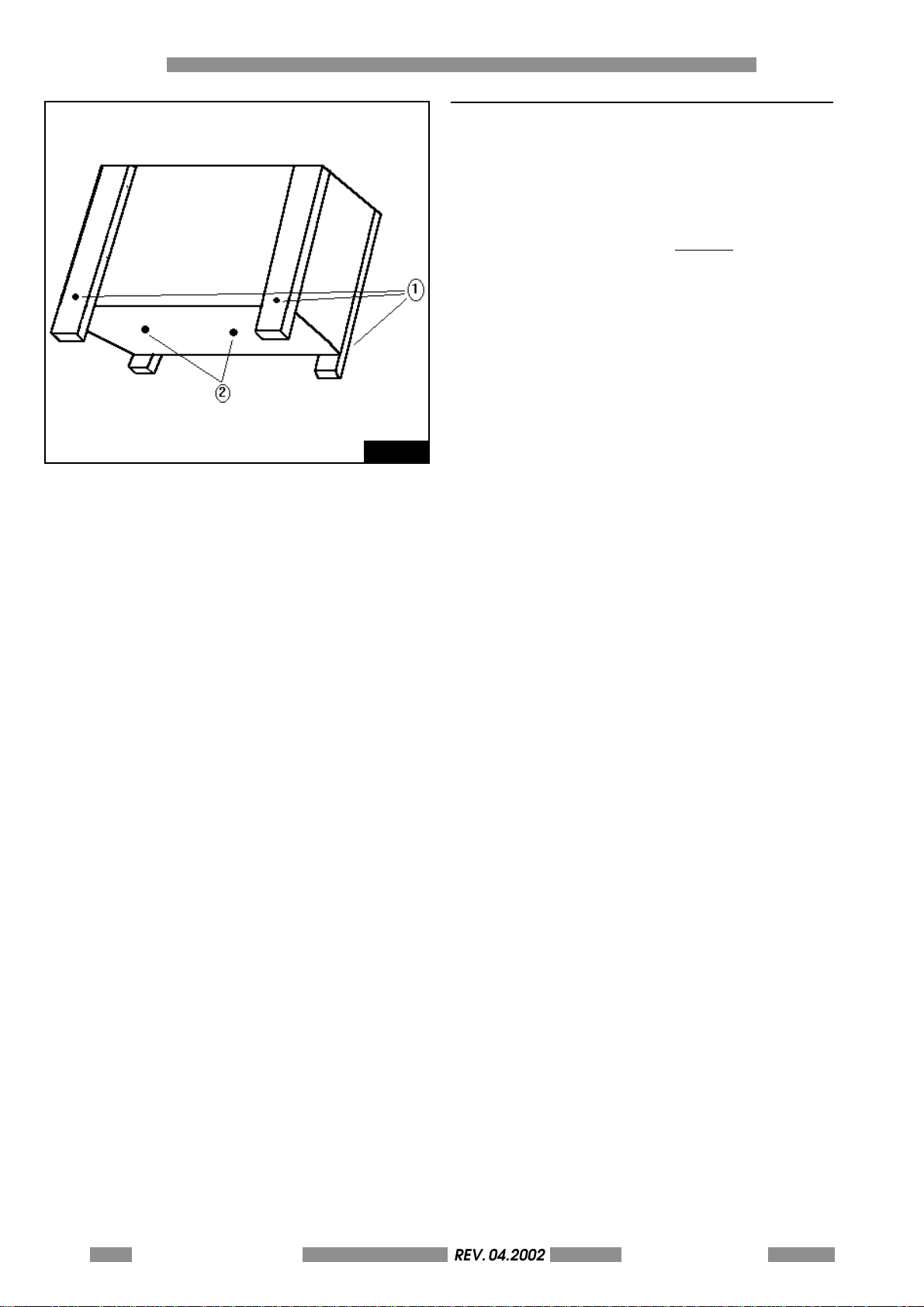
Fig. 2.1
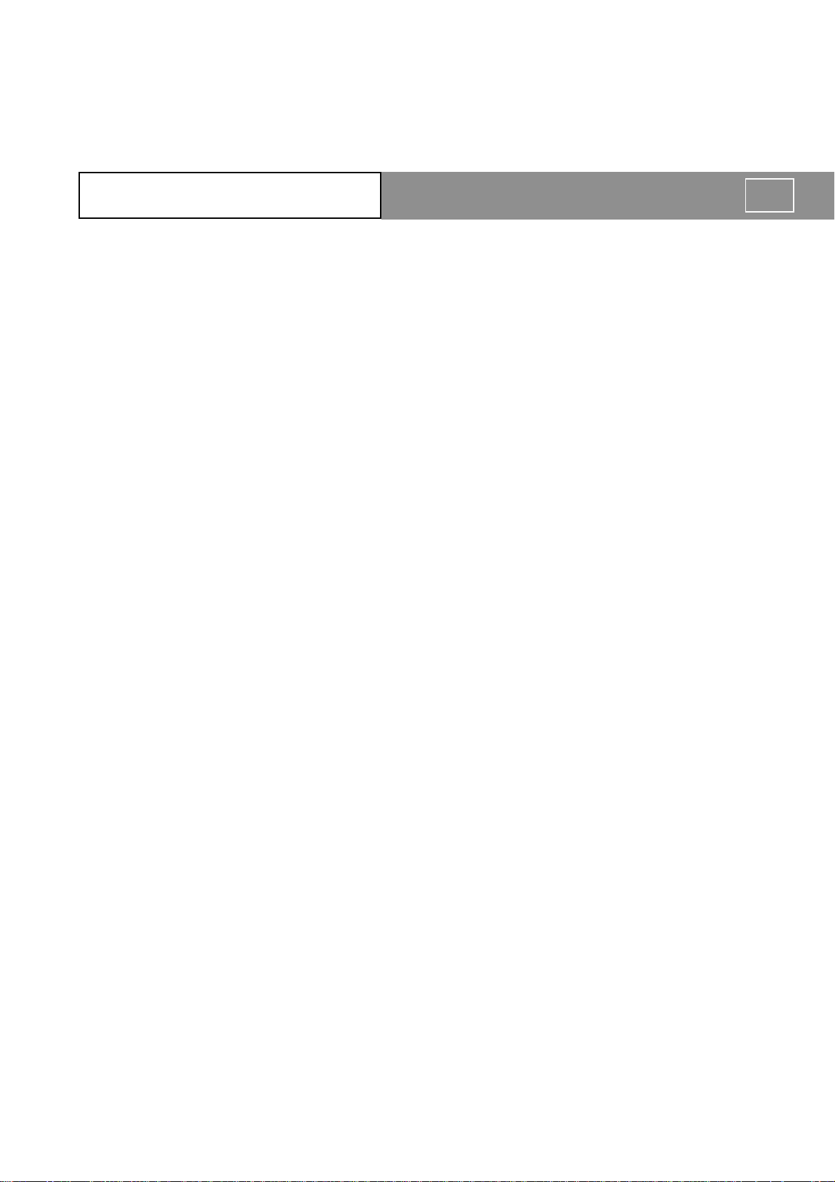
2.0 UNPACKING
The machine is delivered in a wooden packing
case. This is due to its dimensions and weight
and avoids the risk of dammage to the machine.
All displacements should be done by a forklift or
therefore always by two
persons because the
gross weight is about 100 kg. for version METAL
DOT MATRIX 2000 (METAL DOT MATRIX 1000 90
KG.)
To unpack the machine as shown in figure please
follow the instructions below.
- Remove the four side screws (1) with a 10 mm
wrench [es. UNI 6736] and remove the cover.
- Take the 19 mm fork wrench [es. UNI 6736]
which fixed on top of the machine by an
adhesive band.
- Remove the screws from the bottom of the
case (2) with the 19 mm wrench included in
the package.
- Having removed the screws the machine can
be lifted up and placed on the work table.
This operation should be done with two
persons.
- Once the machine has been finally positioned,
the cellophane can be removed. Open the
envelope which contains the cd of manual
and software and the key for the front cover
- Remove the keyboard and with the above
mentioned key open the front lid and remove
the elastic bands which hold the pincer.
- Please refer to the next paragraph in order to
check all the accessories.
2-20 METAL DOT MATRIXREV. 04.2002
OPERATORS MANUAL
Page 21
METAL DOT MATRIX
INSTALLATION 3
3-21
Page 22
3 INSTALLATION
REV. 05-2008
D
C
3.1 CHECKING THE ACCESSORIES
Before installing the machine the operator is
advised to check that all the accessories are
present and that none have been damaged
during the transport.
If any single element has been damaged the
general working of the machine can be
compromised.
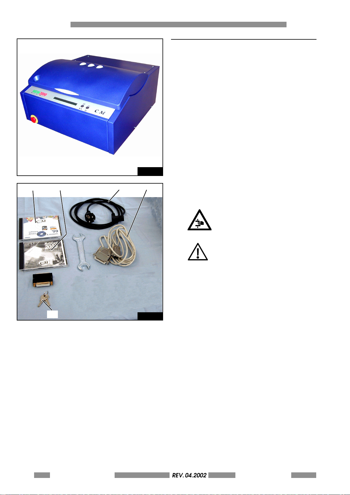
The following accessories are supplied with the
Stamper:
A) 1 POWER SUPPLY CABLE + PLUG TYPE PA80
B) 1 SERIAL CABLE
C) MANUAL ON CD
Fig. 3.1
D) SOFTWARE ON CD
E) 2 KEY LOCK TO OPEN FRONT PANEL
A
B
F) SOFTWARE HARDWARE KEY
WARNING ! THE STAMPING
MACHINE WEIGHS ABOUT 60 KG.
ALL DISPLACEMENTS MUST BE
DONE WITH 2 PERSONS.
WARNING! USE ONLY LISTED
DETACHABLE POWER SUPPLY
CORD NOT EXCEEDING 4.6 M
LENGHT, TYPE SVT OR SJT, 3X18
AWG, WITH A MOLDED-ON CORD
CONNECTION BODY AND A LISTED
PLUG CAP RATED 10A, 125 V.
F
Fig. 3.2
3-22 METAL DOT MATRIXREV. 04.2002
OPERATORS MANUAL
Page 23
3.2 ELECTRICAL CONNECTIONS
REV. 05-2008
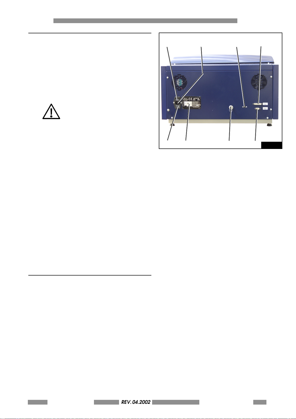
The installation of the METAL DOT MATRIX sys tem
is easily done. Examine the rear control panel of
the cover, (Ref figure 3.3) there are all the sockets
for the various connections. Continue as follows:
- Connect the serial cable between the
Computer and the Stamper
- Connect the power supply cable to the PA 80
socket.
WARNING: TO AVOID ELECTRIC SHOCK
THE POWER CARD PROTECTIVE
GROUNDING CONDUCTOR MUST BE
CONNECTED TO A GROUND CIRCUIT
CONFORMS TO THE NATIONAL
STANDARD.
WARNING: REMEMBER TO CONNECT
THE SERIAL CABLE TO THE MACHINE
WHILE IT IS SWITCHED OFF TO AVOID
DAMAGING THE CIRCUITS.
1. MAIN SWITCH
2. FUSE
3. SOCKET PA80 FOR MAIN POWER SUPPLY
4. IDENTIFICATION PLATE
5. KEY SELECTOR (FOR TECHNICAL USE ONLY)
6. SOCKET TYPE 5 POLE DIN FOR KEYBOARD
7. SERIAL SOCKET FOR PC 25 PIN MALE
8. SERIAL SERVICE PORT
INSTALLATION 3
1
2
4
3
6
5 8
7
Fig. 3.3
The CIM SpA cannot be held responsabile for the
consequences of not abiding by these principles
when using the machine thus in the case of
breadown please call the Technical Assistance.
3.3 CHOOSING THE WORKING PLACE
Install the machine at least 0,6 m of height. Take
care that the place where you install the machine
is conform to the environmental requirments of
cap. 1.8. Leave at least 0,3 m of distance from
each side of the machine and the closer wallsor
barriers in order to permits the better access to
connectors and the proper air conditioning. The
opening of the covers require 0,4 m freespace
also above the cover. Take care that the support
where you put the machine dosen't amplify the
noise level over the allow level (see cap. 1.8) and
that the work station's strenght is suitable to
support the machine (60 kg). Do not install the
machine on unstable surfaces.
METAL DOT MATRIX
REV. 04.2002
OPERATORS MANUAL
3-23
Page 24
3 INSTALLATION
REV. 05-2008
Fig. 3.4
3.4 ADVISE AND CARE DURING THE INSTALLATION
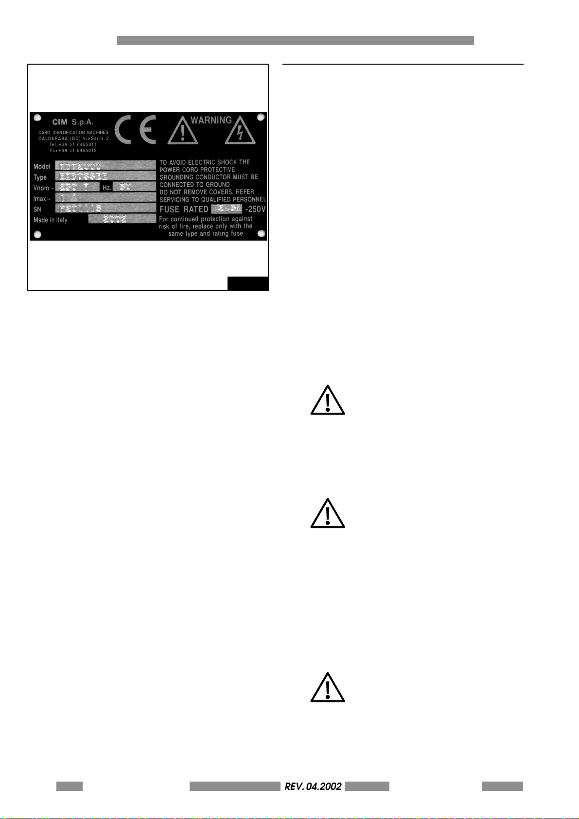
- The Identification plate attached to the rear panel
contains information about the serial number, the
type of machine, the necessary power supply and
the absorbed current.
- Before switching the machine on be sure that all
the cables have been connected correctly and
that the local power supply corrisponds to that
st ated on t he pl ate. The plat e la yout is as fol lows :
(ref. figure 3.4).
After the Trade name the plate has 6 embossed fields
as shown below:
Model : Machine model
Type: Type of machine
Vnom: Power Supply
Hz: Frequency supply
Imax: Power absorbed
SN: Serial Number
- If the tension of the power supply should exceed
a 20% increase of the base tension the safety fastblow fuses could open. In order to substitute it take
a flat blade screw driver, remove the power plug
and place the blade in the nitch at the bottom of
the plug entrance just above the signed area for
t h e f u s e. G e nt l y le v e r t h e Fu s e Bl o c k u n t i l i t c an b e
removed by hand
REPLACE ONLY WITH FUSE OF THE
SAME TYPE AND RATED
- In order to garantee a correct functioning of the
machine and offer a valid safety level to the
operator the machine must be earthed. Please
ensure that the Stamper is connected to a power
supply that has a good earthing and that the
computer is also connected to the same line.
WARNING! USE ONLY LISTED
DETACHABLE POWER SUPPLY
CORD NOT EXCEEDING 4.6 M
LENGHT, 18 AWG RATED 10 A
PROVIDED WITH EARTH PROTECTIVE
CONDUCTOR.
- The electrolock enables the working mode for the
Technician and should be used only by those
specialised persons who have been authorised to
deal with the maintenance and the reparations.
Connect the appropriate cable with the plug
type Cannon 25/9 pin to the serial socket of the
computer and control the conection to the serial
ports COM1, COM 2 in order to report the correct
information when configuring the Software.
3-24 METAL DOT MATRIXREV. 04.2002
OPERATORS MANUAL
NOTE: CONNECT THIS CABLE WHEN
THE STAMPER HAS BEEN SWITCHED
OFF.
Page 25
3.5 SWITCHING ON AND CONTROLLING THE DISPLAY
REV. 05-2008
Once installed the machine can be switched on
with main switch. After few seconds, necessary to
perform a graphics initializzation (shown by a
progress bar), on the display will appear the
following message:
E-00 POWER ON STAND BY STATUS - PRESS START
Press the START key on right side of the front panel
beside the display. This activates a general reset
which, when completed, will leave another
message on the display to indicate the Ready
State of the machine.
METAL DOT MATRIX 2000 V.Y.YY
READY
If the machine does not start control that the
power supply is correctly set and that the main
fuses have not been opened.
For other breakdowns please refer to the Chapter
Error Messages and Problem Solving.
INSTALLATION 3
NOTE: If the display is turned on but nothing
appears on the screen switch the machine off
and call the Technical Assistance.
METAL DOT MATRIX
REV. 04.2002
OPERATORS MANUAL
3-25
Page 26

3 INSTALLATION
REV. 05-2008
This page is left empty
due to editing reason
3-26 METAL DOT MATRIXREV. 04.2002
OPERATORS MANUAL
Page 27
METAL DOT MATRIX
OVERALL DESCRIPTION 4
4-27
Page 28
4 OVERALL DESCRIPTION
REV. 05-2008
4
4.1 OVERALL PARTS DESCRIPTIONS
Components of the machine.
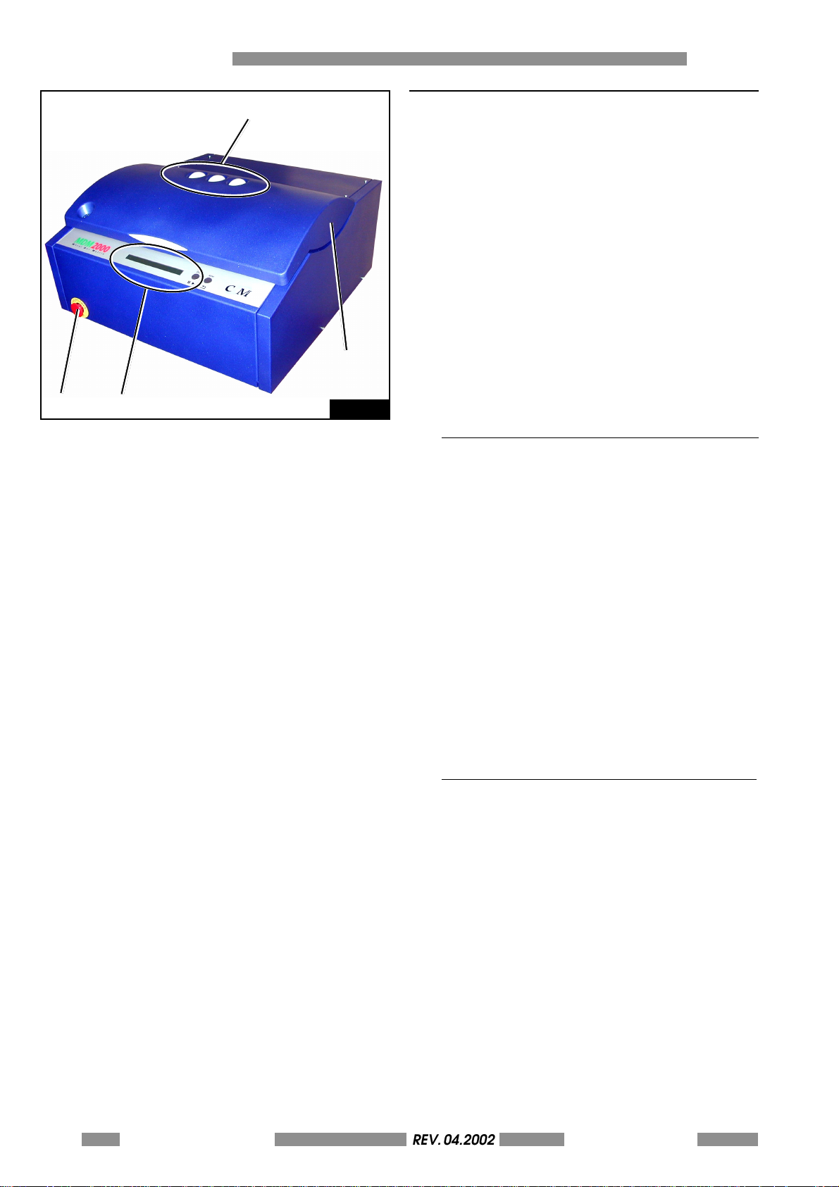
In Fig. 4.1 are showed the main conponents of
the machine:
1. Top Door
2. Safety mushroom pushbutton
3. Operator Console
4. Status lamps
1
2
3
Fig. 4.1
4.1.1 THE TOP DOOR
The TOP DOOR (fig. 4.1 (1)) prevents any contact
of the Operator with the dangerous moving parts
of the machine and should be closed during
work. A mechanical switch with a firmware
protection stop the machine each time the cover
is not well closed.
In case of damage or malfunctioning of this
safety function, please switch off the machine
and call immediately the service.
4-28 METAL DOT MATRIXREV. 04.2002
OPERATORS MANUAL
4.1.2 SAFETY MUSHROOM PUSHBUTTON
(EMERGENCY STOP)
The red MUSHROOM PUSHBUTTON (fig. 4.1 (2)) is
a mantained safety button with turn to reset
head. If any emergency situations occours the
safety mushroom button permits the fastest arrest
of the machine.
The pushbutton doesn't switch off the machine
but stops the mechanical moving part and
remove the power from the motors.
Press the mushroom button to stop the machine
and turn it clockwise to come back to the
operating mode. Then press start to reset the
machine and resume the job.
Page 29
4.1.3 THE CONSOLE
REV. 05-2008
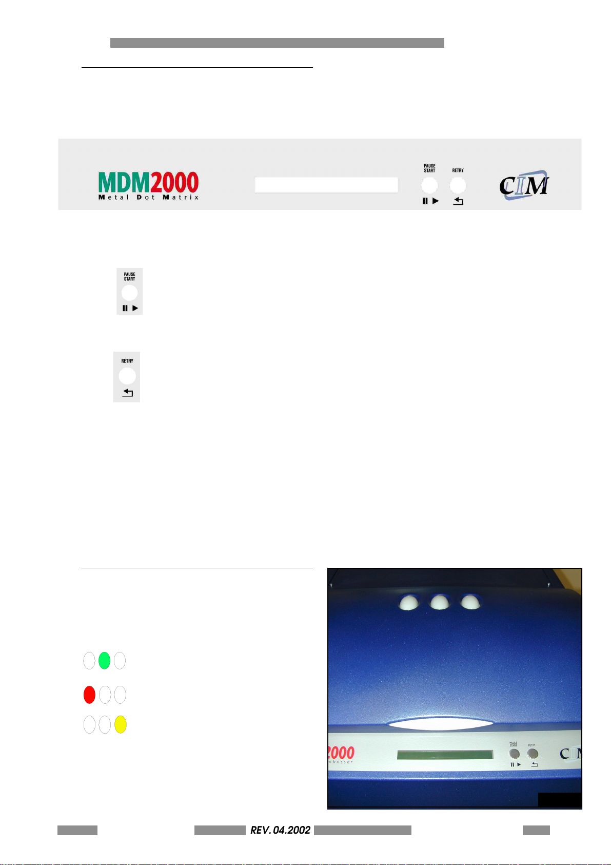
The console of the METAL DOT MATRIX series has
a very simple front control panel with a display
and two buttons.
• The LCD display (2 rows with 40 characters per
row) is used to indicate the operating states of
the machine.
OVERALL DESCRIPTION 4
• The
button is used to switch between
normal operating mode and pause status
and to reset any error.
• The
b u t t o n i s u s e r t o r e t r y t h e l a s t o p e r a t i o n
after an error.
4.1.4 THE INDICATOR LAMPS
On t h e t o p do o r th e r e i s a se g n al e t ic s e ma p h ore
with three coloured light that show in each
moment the status of the machine (fig. 4.2). The
meanings of the light are the following:
GREEN light: READY status (power
supply ON)
RED light (flashing): ERROR status
(with buzzer acoustic alarm)
YELLOW light (flashing): WARNING
status (Loader EMPTY or Unloader
FULL
In normal use the green light is always on. The
other light can be switched on during the
functioning. Uses the PAUSE/START and RETRY
buttons to resume the job.
METAL DOT MATRIX
REV. 04.2002
OPERATORS MANUAL
Fig. 4.2
4-29
Page 30
4 OVERALL DESCRIPTION
REV. 05-2008
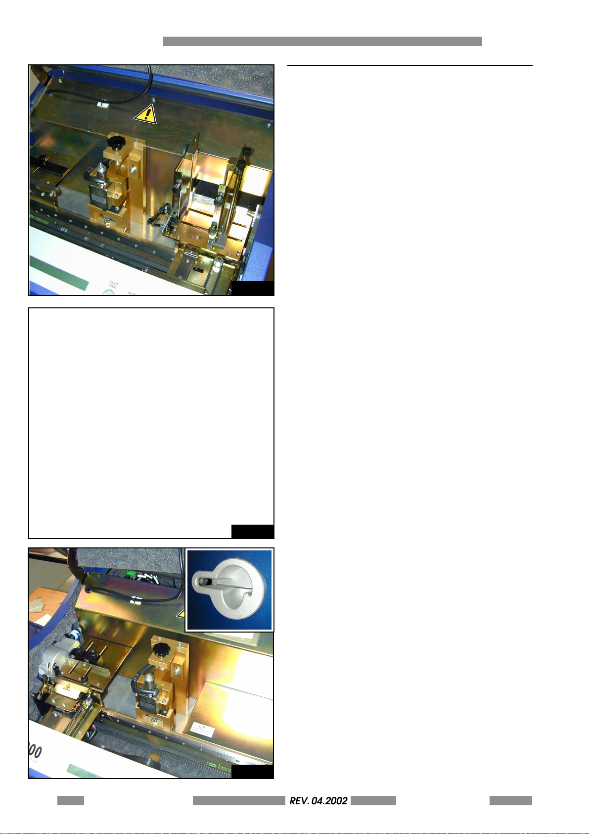
4.2 DIFFERENCES BETWEEN MANUAL (1000) AND AUTOMATIC (2000) MODELS
The METAL DOT MATRIX 2000 has a loader unit
(right to the stamper unit) that contains up to 200
metal plates, and an unloader magazine (on the
left) to deposit the personalized plates (fig. 4.3).
Two alarms are provided in case of LOADER
EMPTY or UNLOADER FULL.
Fig. 4.3
da fare
Fig. 4.4
The MDM1000 version doesn't have magazine of
metal plates (see fig. 4.4), so it can personalize
only 1 plate at time.
On the left enclosure side there is an opening that
will permit to insert and remove the plate (fig.
4.5).
Use this opening to put a new plate and to
remove it when the cicle of personalization is
finish. Remove the old plate before to start a new
cicle.
A photocell will stop the unloading movements
each time you put your hand in the hole.
Fig. 4.5
4-30 METAL DOT MATRIXREV. 04.2002
OPERATORS MANUAL
Page 31
4.3 STORED CONFIGURATION AND REPLACING
REV. 05-2008
LITHIUM BATTERY
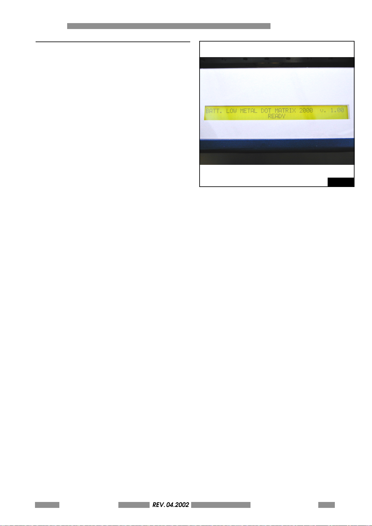
The LCD EDIT format and the SETUP configuration
parameters (see Annex A and B) are stored into
a memory provided of a lithium backup battery.
W h e n t h e b a t t e r y l e v e l i s d o w n t h e m a c h i n e m a y
lost the configuration and the LCD Edit formats.
B e f o r e t h i s c r i t i c a l l e v e l i s r e a c h e d , t h e d i s p l a y w i l l
show the alarm "BATT LOW" (see Figure) and the
red lamp will flash for 5 seconds.
In this case call the service in order to replace the
battery.
CAUTION: DANGER OF EXPLOSION IF BATTERY IS
INCORRECTLY REPLACED. REPLACE ONLY WITH
THE SAME OR EQUIVALENT TYPE RECOMMENDED
BY THE MANUFACTURER. DISPOSE OF USED
BATTERIES ACCORDING TO THE MANUFACTURERS
INSTRUCTIONS
OVERALL DESCRIPTION 4
Fig. 4.6
METAL DOT MATRIX
REV. 04.2002
OPERATORS MANUAL
4-31
Page 32

4 OVERALL DESCRIPTION
REV. 05-2008
This page is left empty
due to editing reason
4-32 METAL DOT MATRIXREV. 04.2002
OPERATORS MANUAL
Page 33
METAL DOT MATRIX
HOW TO PRODUCE ONE CARD 5
5-33
Page 34
5 HOW TO PRODUCE ONE CARD
REV. 05-2008
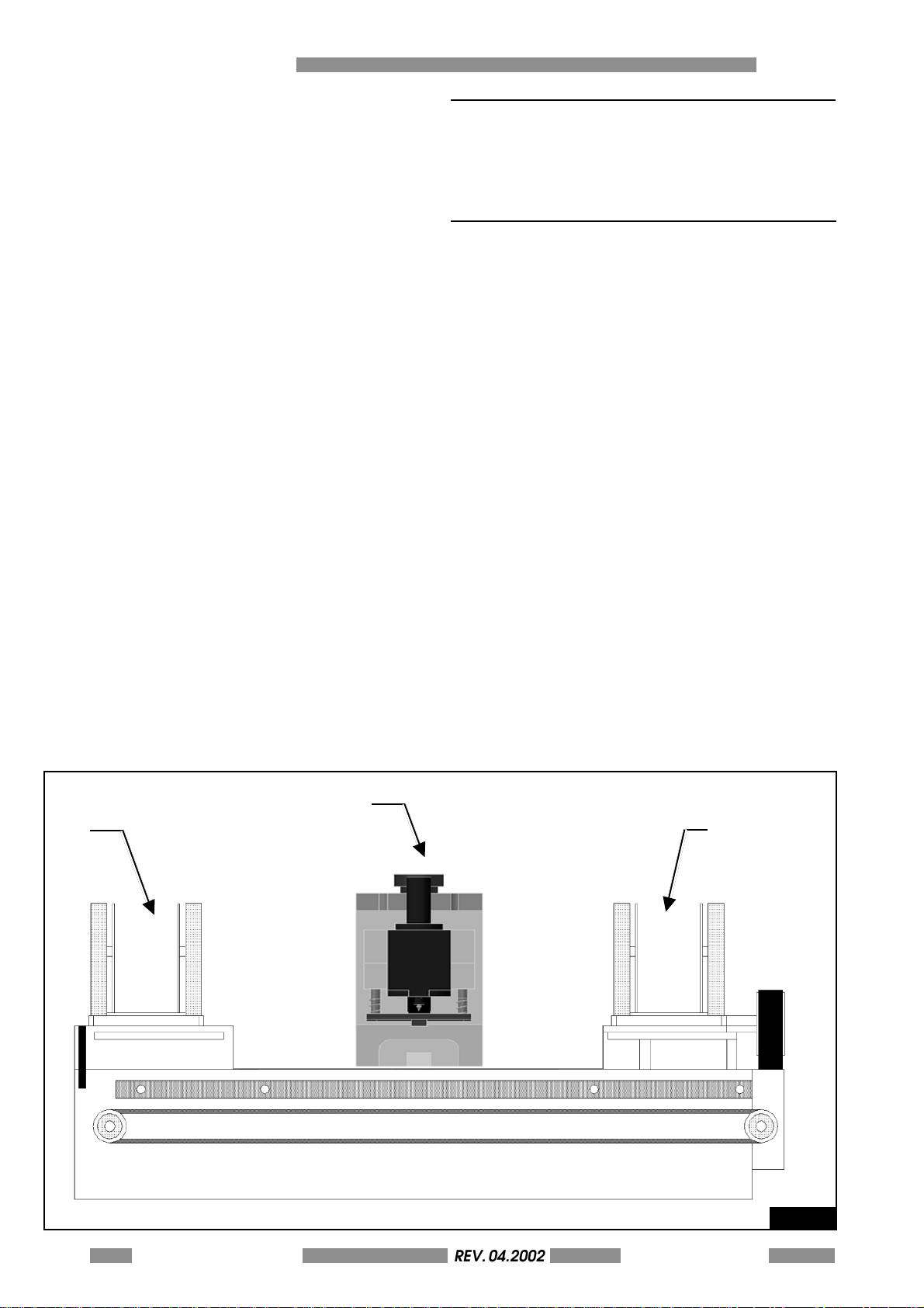
5.0 HOW TO PRODUCE ONE CARD
Before to start with your first card you have to set
the machine, switch on the machine and run the
SWORD software.
5.1 SETTING THE MACHINE
Before to start with the production it need to
adjust the internal devices to the plates sizes to
product.
The quality and quantity of the produced plates
depend on the correct adjusting of the
mechanical units.
• Loader
• Unloader
• Stamper
Open the front panel (after input the key supplied)
the METAL DOT MATRIX as shown in figure 5.1.
1. PLATES LOADER
2. STAMPING DEVICE
3. PLATES UNLOADER
It should control the state of the above mentioned
units at the begining of every work cycle.The
machine should be switched off and the power
supply should be disconnected when it is
necessary to access any of the internal parts of
the machine. The safety protection devices have
been constructed to block the machine cyle
during the adjusting phase if the preceding
standards are not respected.
2
3
1
5-34 METAL DOT MATRIXREV. 04.2002
OPERATORS MANUAL
Fig. 5.1
Page 35
5.1.1 AUTOMATIC (2000) VERSION
REV. 05-2008
HOW TO PRODUCE ONE CARD 5
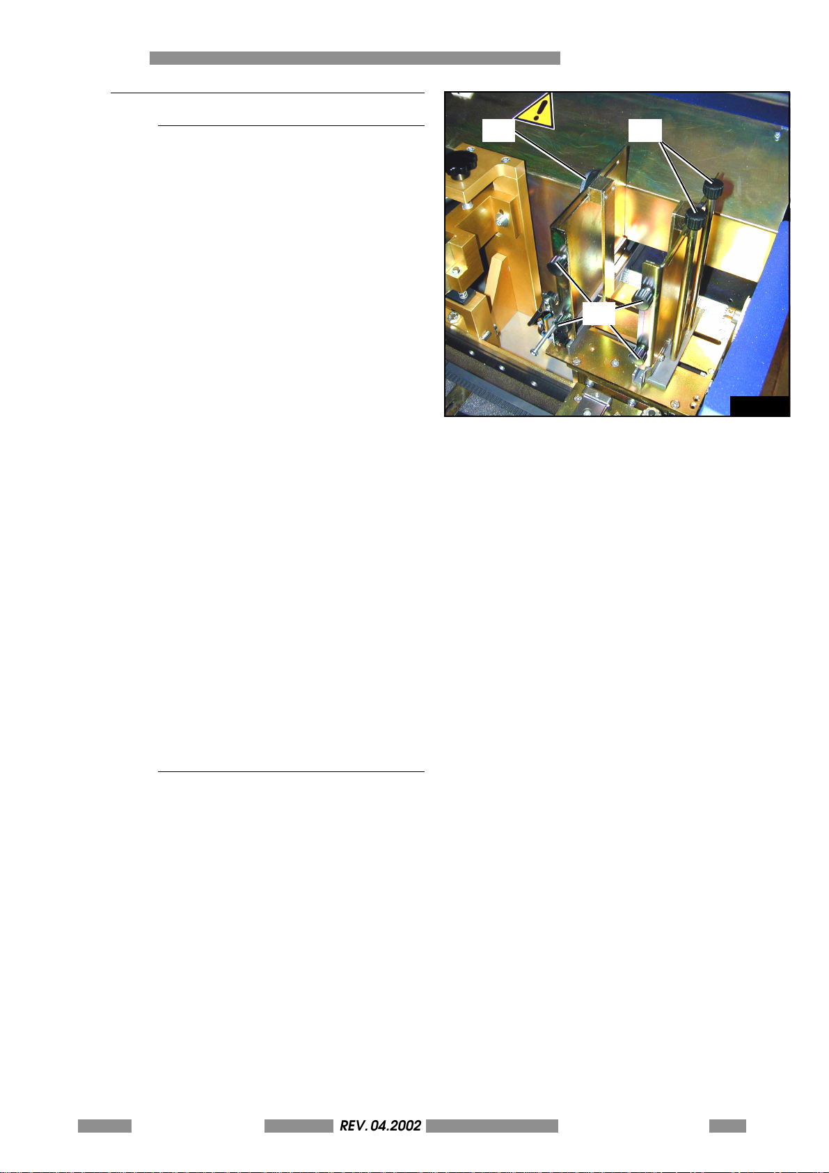
5.1.1.1 LOADER ADJUSTEMENT
The Loader unit for the metallic plates (fig.
5.2) is located on the right side of the
Stamper and can be adjusted to the
dimensions of the plates.
To adjust the Loader do as follows:
• Open the front cover.
• Loosen the black knobs (1) on the right
side of the Loader.
• Bring the right support closer to the
plate to be embossed leaving a
tolerance of about 1 mm and then
tighten the knobs.
• Loosen the wings knobs (1) of the rear
supports (2), slide them to a distance
of about 5 mm from the plate and
tighten the knobs.
• Loosen the four knobs (3) to adjust the
plate thickness, pull the plate towards
the outside, set the supports 0.5 mm
higher and tighten the knobs.
12
3
Fig. 5.2
5.1.1.2 UNLOADER ADJUSTEMENT
The Unloading unit is located on the left
s i d e o f t h e S t a m p e r . T h e r e a r e t w o d i f f e r e n t
adjustment solutions depending the type
of plate and end use:
• Unloader with Lift (5.1.1.3)
• Unloader with Ejector (5.1.1.4)
The first permits a progressive stacking of
the plates inside the Metal Dot Matrix and
the second ejects the plates out of the
Stamper.
METAL DOT MATRIX
REV. 04.2002
OPERATORS MANUAL
5-35
Page 36
5 HOW TO PRODUCE ONE CARD
REV. 05-2008
5
4
5
Fig. 5.3
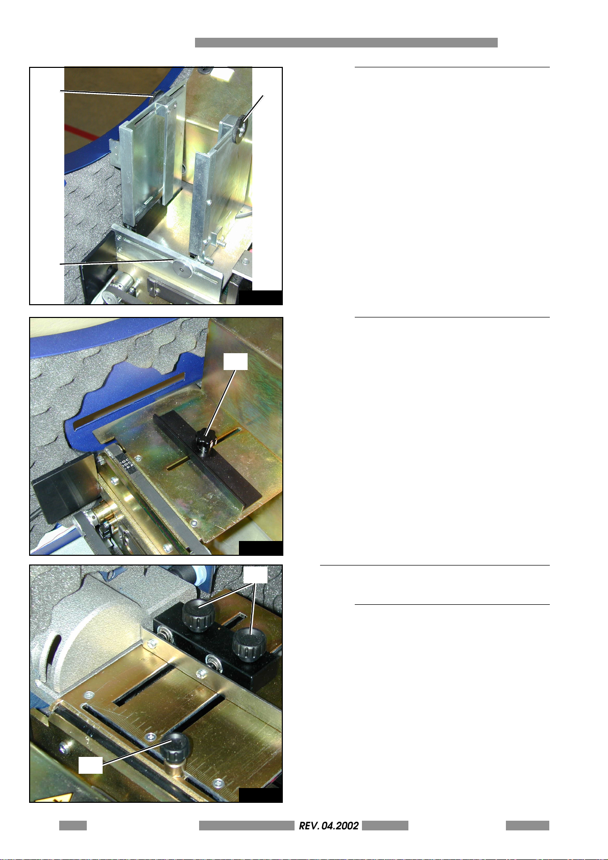
5.1.1.3 UNLOADER LIFT ADJUSTEMENT
To adjust the unloading support refer to
figure 5.3 and follow the instructions below:
• Open the front cover.
• Loosen the knob on the bottom of the
support (4).
• Place the plate on the spring support.
• S h ift t he r i ght s upp o rt t o war d s th e pla t e
until there is a gap of about 1 mm
• Tighten the knobs .
• Loosen the knobs (5) and repeat the
process mentioned in the Loader
section.
5.1.1.4 UNLOADER EJECTOR
ADJUSTEMENT
1
In the machines with unloading ejectors
(fig. 5.4) there is only one adjustment:
• Loosen the black knob (1) [cilindric
nut UNI 5723-67/4A]
• Place a plate on the ejector plane.
• Shift the bracket towards the plate.
Leave a gap of a few millimeters
between the two.
• Tighten the black knob.
Fig. 5.4
2
5.1.2 MANUAL (1000) VERSION
5.1.2.1 LOADER/UNLOADER ADJUSTMENT
To adjust the loading/unloading (fig. 5.5)
do as follows:
• Open the front cover.
• Loosen the black knob on the right
side of the loader (1) and slide it closer
to t h e p l a te t o be e mbo s sed l eav i ng a
tolerance of about 1mm and then
tighten the knob.
• Lo osen the k nobs of th e reart su pport
(2).
1
• Bring the rear support to a distance of
about 5mm from the plate and tighten
Fig. 5.5
the knobs.
5-36 METAL DOT MATRIXREV. 04.2002
OPERATORS MANUAL
Page 37
5.1.3 STYLUS ADJUSTMENT
REV. 05-2008
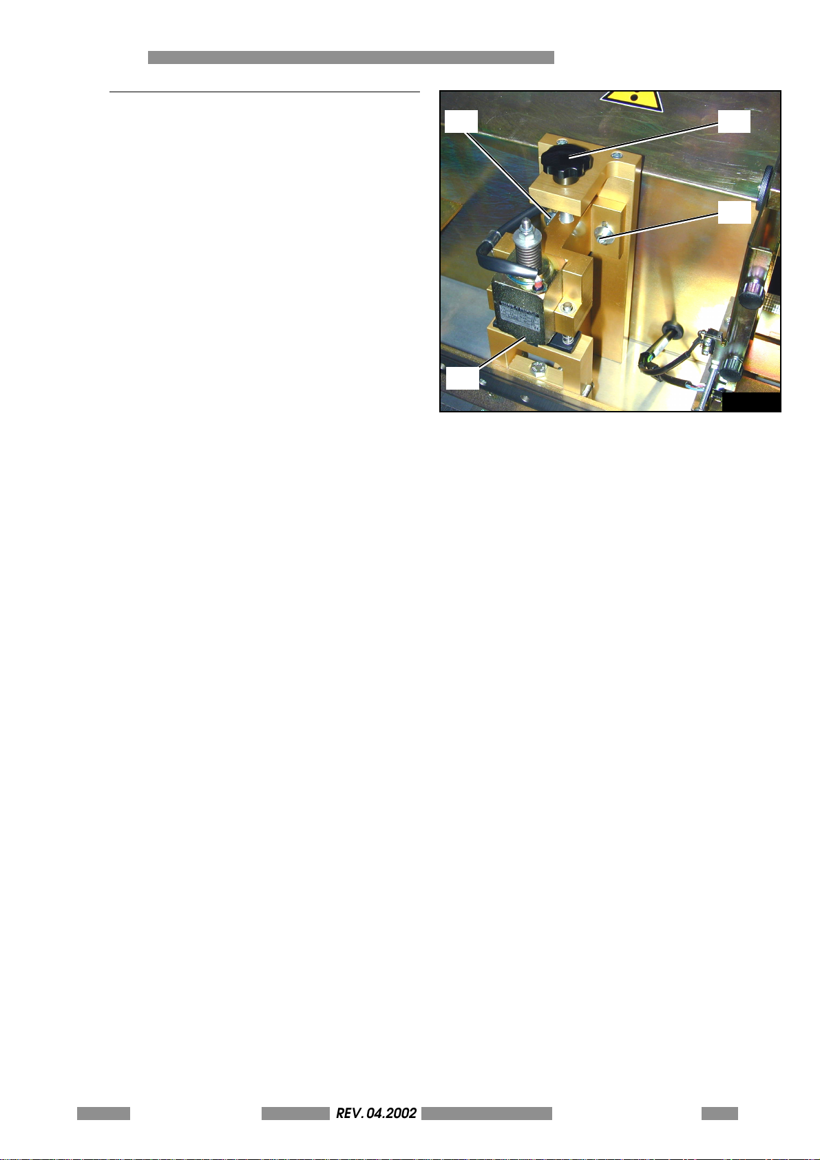
The machine is configured by the constructor in
the final testing phase for the production of
alluminium plates of thickness 0,5mm.
For steel plates or for plates of greater thickness it
is ne cessa ry to m odify the he ig ht of the st yl us (3 ).
To registry the stylus refers to fig. 5.6 and do as
follow:
- Switch off the machine and lift the front cover.
- Loosen the allen screws (1).
- Turn the black knob (2) clockwise or
counterclockwise in order to increase or
decrease respectively the height of the stylus.
- Tighten the allen screws (1).
To reach the best calibration we suggest to
carefully attend to the following steps:
1. Loose the allen screws (1);
2. By using the knob (2) increase the height of the
stylus in order to insure the passage of the
plate;
3. Put the plate in the clamp and manually
move the clamp until the plate is in the working
position (under the stylus);
4. By keeping lower the solenoid with your finger,
turn the knob (2) until the stylus goes in contact
with the surface of the plate (don't press the
surface).
5. Tighten the allen screws (1).
6. Close the cover, switch-on the machine and
start the Card-Test Nr. 1 (see annex A.10);
7. Looking the resulting plate you can see if you
need more pressure.
8. To increase the pressure loose the allen screws,
turn the knob counterclockwhise of about 1015° (1 complete turn= 1,25 mm height), tighten
the screws and repeat the card test.
9. If necessary repeat steps 7 and 8 until the result
is acceptable.
HOW TO PRODUCE ONE CARD 5
2
2
1
3
Fig. 5.6
Remarks: the Stylus Adjustment is a delicate
operation. Do it only when tightly necessary or
when the printing of your MDM is not satisfying.
After each regulation of the knob set free the
solenoid and verify that the plate is free to pass
under the stylus. Remember that careless or wrong
settings may cause serious damage to the structure
of the stamper.
METAL DOT MATRIX
REV. 04.2002
OPERATORS MANUAL
5-37
Page 38
5 HOW TO PRODUCE ONE CARD
REV. 05-2008
5.2 SWICHING ON THE MACHINE
Connect the serial cable to the PC with the Sword
software then switch on the machine (see chapter
3 "Installation" fig. 3.2).
If the machine does not start (verify display light
and fans) controle that the power supply is
correctly setted and that the main fuse has not
opened.
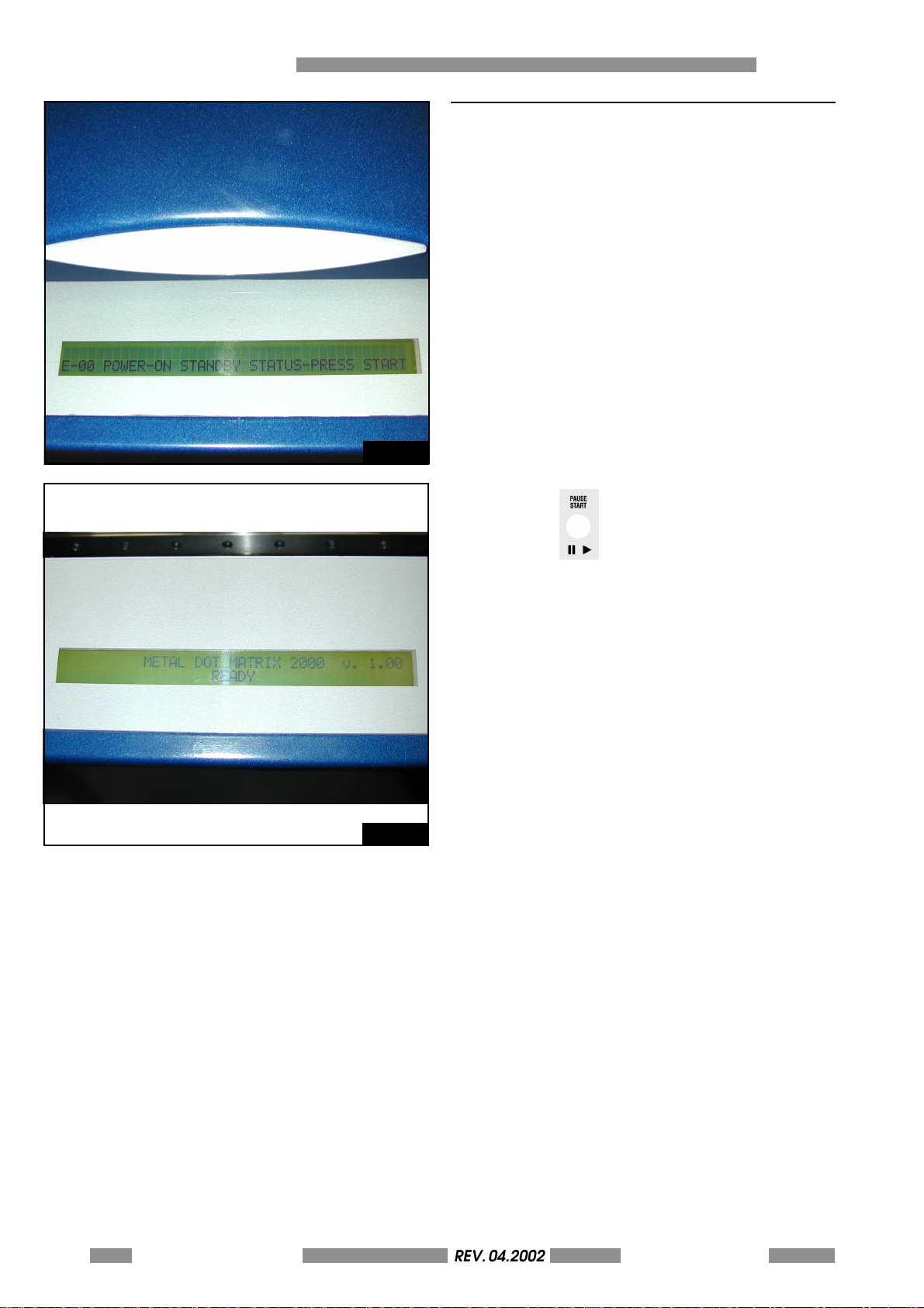
When the machine is switched on after the
initialization control that the display show as in
figure 5.7.
Fig. 5.7
Fig. 5.8
Press the key on front panel to make a
general reset. If the machine does not start and
the display message does not change please
verify that the top cover is closed and the red
mushroom pushbutton is not pressed, then retry.
The machine will make a reset cycle and the
display will show the model of the machine, the
Fw release with the READY status (as show in fig.
5.8) (the model will be "METAL DOT MATRIX 1000"
if you have the manual version).
N OT E: IF TH E DI S PL A Y I S TU RN ED ON B UT NO TH IN G
APPEARS ON THE SCREEN SWITCH THE MACHINE
OFF AND CALL THE TECHNICAL ASSISTANCE.
For other breackdowns please refer to the
appropriate chapter 7 "TROUBLE SHOOTING".
The machine is now ready to run. If the Software
SWORD has already been installed on the PC, the
machine can start the production immediately. If
however another Software is used it is necessary
to control the relative parameters for the
communications protocol. To do this one enables
the Machine Setup from the console (refers to
advanced chapter for details).
5-38 METAL DOT MATRIXREV. 04.2002
OPERATORS MANUAL
Page 39
5.3 INSTALL THE SOFTWARE "SWORD"
REV. 05-2008
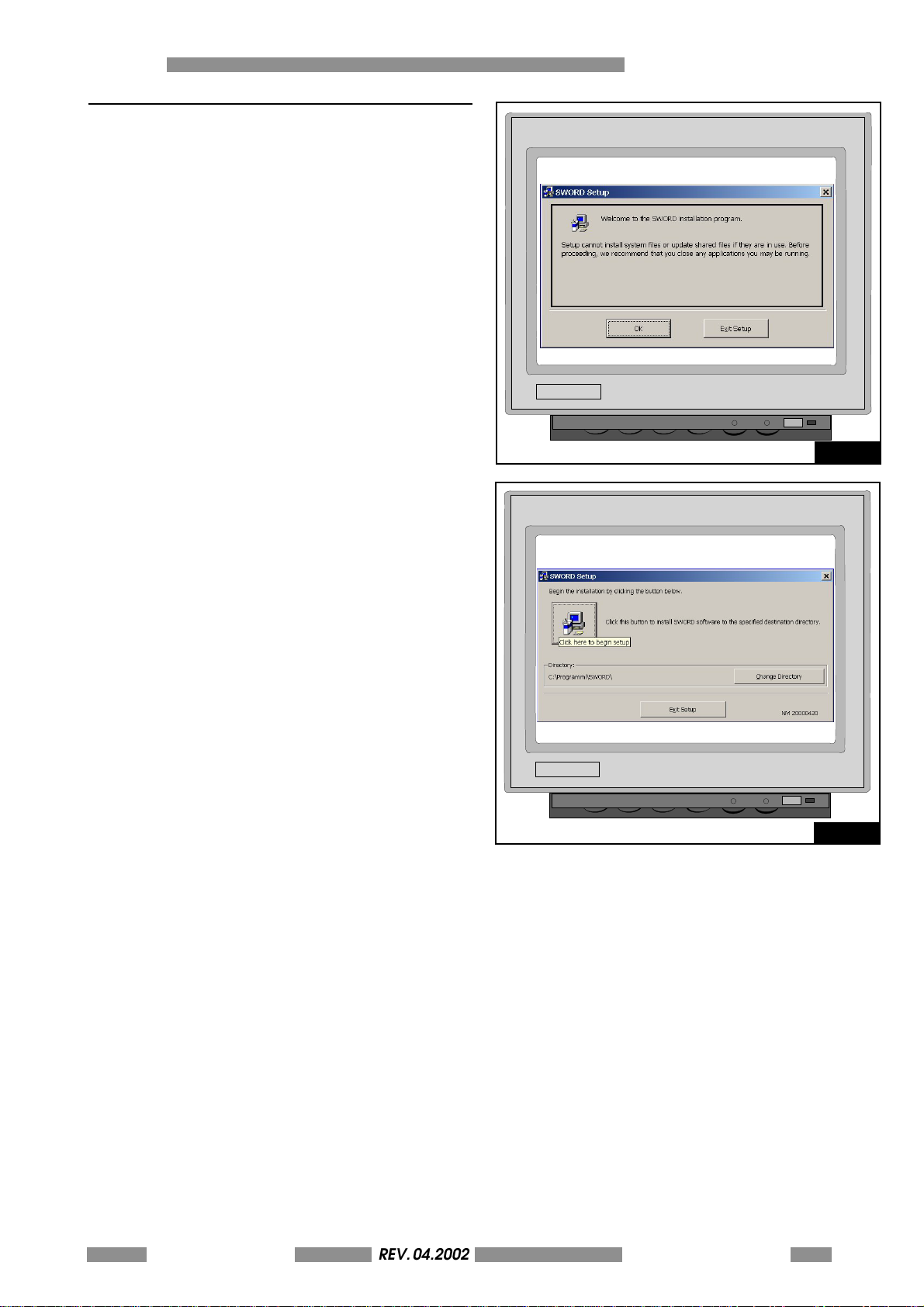
Close all current applications and insert the
SWORD CD-ROM on your PC.
The Setup windows will appear after few moments
(fig. 5.9):
Close any applications and press OK to continue.
If necessary chose your favorite folder to install
(Change Folder) and press the button on the left
to start the setup (fig. 5.10).
HOW TO PRODUCE ONE CARD 5
Fig. 5.9
Press Continue until the installation is finished.
For more details about installation and setting
please refere to the SWORD USER'S MANUAL.
Fig. 5.10
METAL DOT MATRIX
REV. 04.2002
OPERATORS MANUAL
5-39
Page 40
5 HOW TO PRODUCE ONE CARD
REV. 05-2008
5.4 RUN THE PROGRAM AND PRODUCE ONE CARD
As soon as the stamper , the Software and the
serial connection to the Host computer have
been succesfully installed, card production can
be started.
Switch on the machine and press the START key
on the front panel when ready.
Load an appropriate number of plate in the
loader (max. 200 for 2000 model) or put the plate
in the right side load opening (1000 model) and
close the top door.
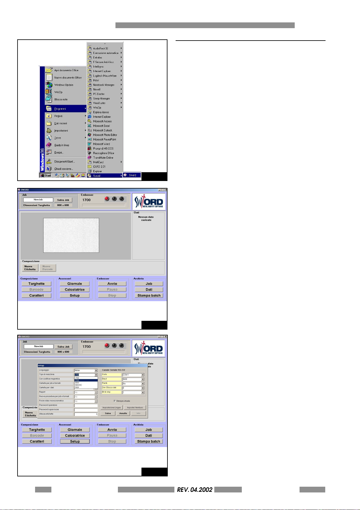
Select the shortcut from the Program menu of
your PC to run SWORD (fig. 5-11).
Fig. 5.11
The windows shown in fig. 5.12 will appear on
your PC.
The square in center of the windows represents
the layout of your plate.
To modify the dimensions of the plate press the
"TARGHETTE" button.
Fig. 5.12
T o se t th e t he s o f t wa r e i n o rd e r t o us e yo u r M E TA L
DOT MATRIX press the SETUP button and OK in the
following Password window (fig. 5.13).
Select TIPO DI MACCHINA= METAL DOT MATRIX
and press "Salva".
Fig. 5.13
5-40 METAL DOT MATRIXREV. 04.2002
OPERATORS MANUAL
Page 41
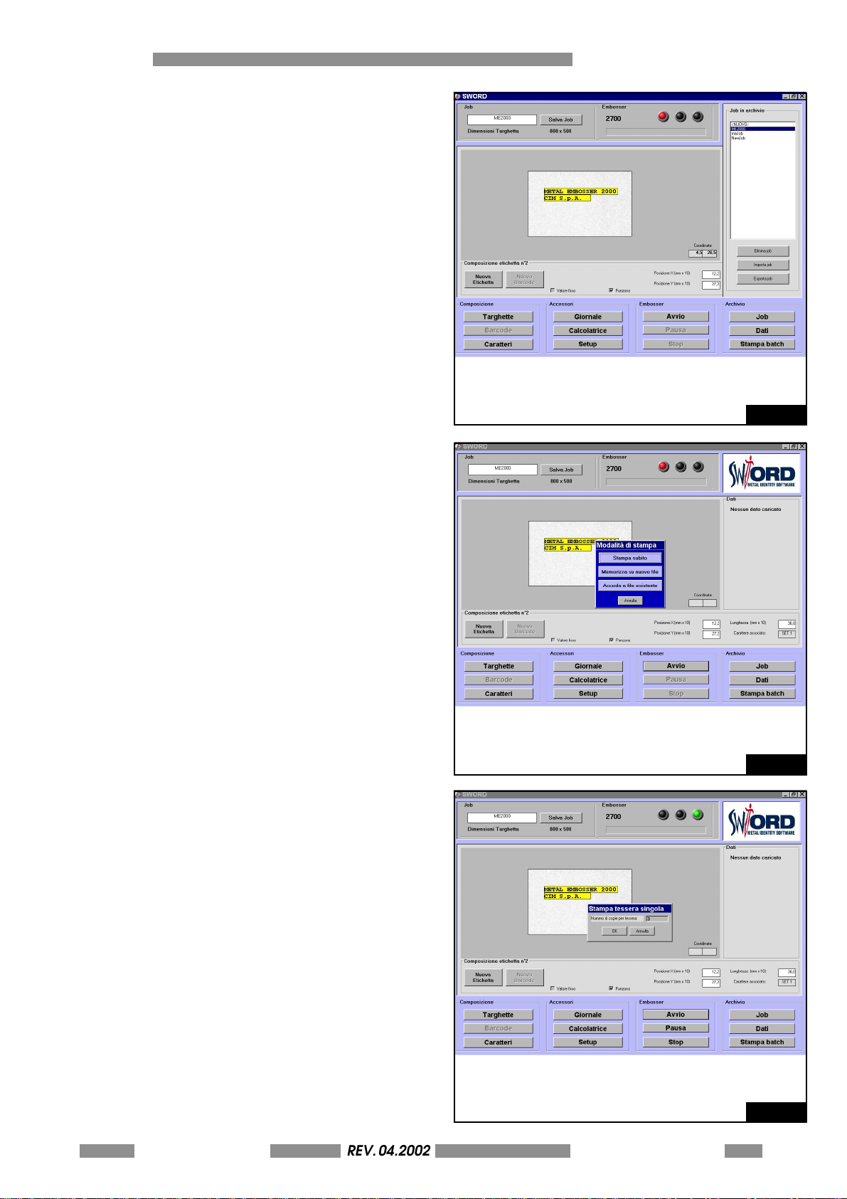
To define a layout do the following steps:
REV. 05-2008
Press the "Nuova Etichetta" button on the main
box and double click in the yellow box will
appear. Type a symbolic text (i.e. "METAL DOT
MATRIX 2000" in the example) and press Enter.
Add the text boxes you need by repeating the
last steps. You can move each box by drug&drop
or writing the coordinates in the "Posizione X",
"Posizione Y" and "Lunghezza" boxes.
Type the name of the new job in the Job box (i.e.
"METAL DOT MATRIX 2000") and press "Salva Job".
The windows will appear as shown in fig. 5.14.
Now you can recall the job by means of the JOB
button in the archivio box on the right.
After these steps you are ready to print your first
plate. Press the AVVIO button to start the
production.
Press "Stampa subito" on the following box.
HOW TO PRODUCE ONE CARD 5
Fig. 5.14
In the next window you can type the number of
card you want to print. Then press OK (fig. 5.16).
The machine will print the specified number of
plates with the current job text layout.
If errors don't have occurred the MDM2000 stop
the work and go to READY status.
If errors have occurred during the working cycle
the Stamper will indicate the error codes on the
LCD display. Please refer to the chapter 7 "Trouble
Shooting" for a description of the errors.
Open the top door and remove the plate just
personalized from the unloader magazine on
the left of the stamping unit.
METAL DOT MATRIX
REV. 04.2002
OPERATORS MANUAL
Fig. 5.15
Fig. 5.16
5-41
Page 42

5 HOW TO PRODUCE ONE CARD
REV. 05-2008
This page is left empty
due to editing reason
5-42 METAL DOT MATRIXREV. 04.2002
OPERATORS MANUAL
Page 43
METAL DOT MATRIX
MAINTENANCE 6
6-43
Page 44
6 MAINTENANCE
REV. 05-2008
6.1 SCHEDULED LUBRICATION
This section describes the operations to be carried
out at regular intervals to ensure correct machine
functioning.
THE MAINTENANCE OPERATIONS
DESCRIBED IN THIS SECTION MUST BE
CARRIED OUT RIGOROUSLY TO ENSURE
CORRECT FUNCTIONING AND LONG
LIFE FOR YOUR MACHINE.
IF THE MAINTENANCE OPERATIONS
ARE NOT CARRIED OUT IN
ACCORDANCE WITH THE
INSTRUCTIONS PROVIDED, CIM IS NOT
RESPONSIBLE IN ANY WAY FOR
MACHINE PROBLEMS AND
MALFUNCTIONS.
The following table indicates the maintenance
program recommended by CIM.
GROUP and/or UNIT REGULARITY
Load and unload unit every 100 hours
Carriage unit every 100 hours
IT IS FORBIDDEN TO REMOVE THE COVER AND THE
PROTECTIONS PRESENT INSIDE THE STAMPER.
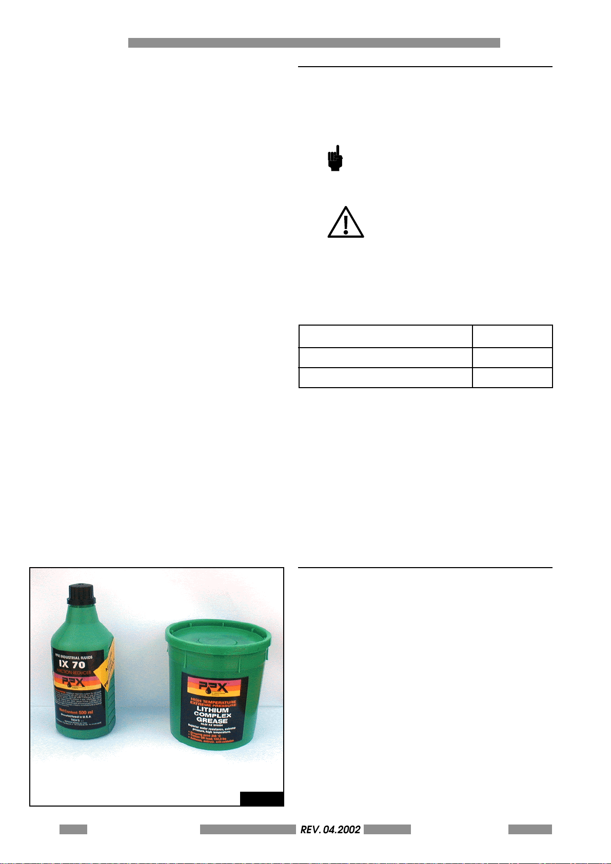
6.2 RECOMMENDED LUBRICANTS A) RECOMMENDED OIL
TYPE: PPX INDUSTRIAL
MODEL: IX70/50 FRICTION REDUCER
MANUFACTURER: PPX ITALIA
A
6-44 METAL DOT MATRIXREV. 04.2002
OPERATORS MANUAL
B
Fig. 6.1
B) RECOMMENDED GREASE
TYPE: PPX INDUSTRIAL
MODEL: LITHIUM COMPLEX GREASE
MANUFACTURER: PPX ITALIA
Page 45
6.3 GENERAL MAINTENANCE BY THE OPERATOR
REV. 05-2008
The operator should make a habit of doing
general maintenance on the Stamper so as to
ensure a correct and long lasting functioning of
the system. The operations are simple but for
maintenance inside the machine it is necessary
to call the Technical Assistance. Thus it is
absolutelyThe routine maintenance is as follows:
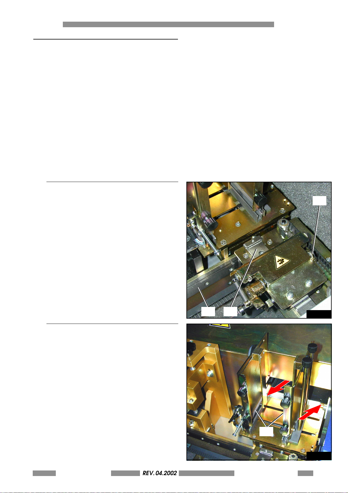
6.3.1 TROLLEY-TRUCK OILING
MAINTENANCE 6
The oiling of the trolley truck should be done
every six month, if the machine works 8 hours/
day, using vaseline oil:
• Oil the clamp's trolley guide (1) top and
bottom moving the trolley by hand back and
forth to assure an even distribution of the oil
and to control the fluidity of the movement.
• Oil the clamp guide (2) in the same way as
above moving the clamp by hand and
controlling for unhindered movement. In case
of friction or jamming which persists call the
Technical Assistance
• Remove any excess oil.
• Oil the camshaft (3).
6.3.2 PLATE LOADER OILING
• Oil t he holes of the plate loa der group shown
in the figure.
Repeat this operation every 20 days or every 1500
produced plates.
Every 6 months the internal mechanical parts
should receive a general oiling. This can be done
however only by a specialised person.
When the general maintenance is finished switch
the stamper on and control that the front cover
blocks all operations. If this not the case call the
Technical Assistance because one or more safety
devices could be dammaged.
Oil with vaseline the guide of the pushers (1).
3
2
1
Fig. 6.2
1
METAL DOT MATRIX
REV. 04.2002
OPERATORS MANUAL
Fig. 6.3
6-45
Page 46
6 MAINTENANCE
REV. 05-2008
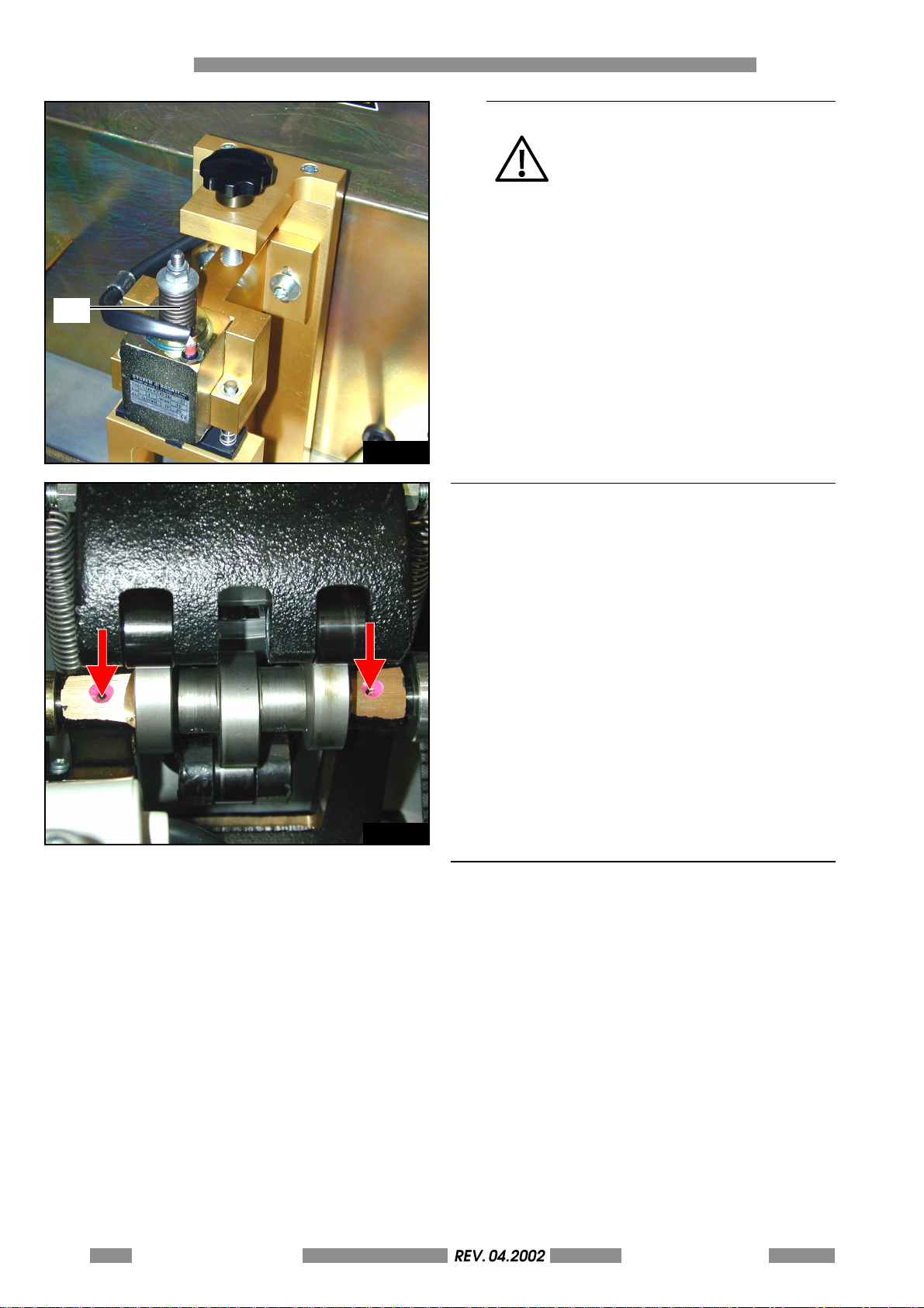
1
6.3.3 STAMPING UNIT
NEVER USE OIL OR OTHER KIND OF
LUBRICANTS ON THE PIN (1) OF THE
SOLENOID
Fig. 6.4
6.4 UNLOADER LIFTER
Fig. 6.5
Oil with vaseline the unloader lifter's vertical
guide.
6.5 SAFETY INTERLOCK SWITCH FUNCTIONAL TEST
To work in safe condition it is necessary that the
interlock switch of the cover works properly.
B ef o re to s ta r t t he w or k s e ss i on (a t le as t on e ti me
per day) open the top cover and verify tha the
machine switch in PAUSE mode. Then close the
covers and press start to resume the job. If the
machine dosen't switch in PAUSE status it means
that the interlock switch is demaged. In this case
please switch off the machine and call the service.
6-46 METAL DOT MATRIXREV. 04.2002
OPERATORS MANUAL
Page 47
METAL DOT MATRIX
TROUBLE SHOOTING 7
7-47
Page 48
7 TROUBLE SHOOTING
REV. 05-2008
7.1 ERROR MESSAGES AND PROBLEM SOLVING
In case of breakdown or operator error the machine will show on the display a message starting the cause
of the cycle interruption. The error signal is shown by an error code followed by the corrisponding message.
Please consult the table for more information in order to resolve the problem.
After having corrected the error condition press the START key on the machine in order to restore the
working state of the Stamper
CODE MSG POSSIBLE SOLUTION
E-00 POWER ON STAND BY
STATUS - PRESS START
E-01 OUT OF CARDS - PRESS
START OR RETRY
E-02 CARD MISFEED - PRESS
START OR RETRY
E-05 X MOTOR ERR-CHECK
CARD/PRESS START
E-06 Y MOTOR ERR-CHECK
CARD/PRESS START
E-09 EMERGENCY STOP-
PRESS START
E-10 PAUSE STAMPING - PRESS
START
E-13 PUSHER MOTOR ERROR -
PRESS START
Machine expecting the RESET command.
Press START.
Loader empty.
Add plate into the Loader.
The clamp has not keep the plate.
Press Feed once more or check the loader.
The trolley clamp has struck during the work cicle.
Check the defects on the plates.
Clamp error.
Check the defects on the plates.
The emergency stop button has been pressed.
Turn the mushroom button clockwise and press start to come back to the
operating mode.
Lost Mask.
Call the technical assistance.
The pusher motor do not return in home position.
Check the plate loader is jammed.
E-16 USER REJECTED CARD-
PRESS/START
E-28 LOST SEMIPERMANENT
DATA - PRESS START
E-30 LOGOS DISABLED - PRESS
START
The user has press the ABORT key while the machine stamps.
Press START.
Lost data on Main Logic Board.
Call the technical assistance.
Request of stamping logo but logo disabled.
If necessary enable the print of the logos from setup (see "stamping
configuration" menu).
E-31 LOGO 1 LOST-PRESS START
Logo 1 damaged in the equipment memory.
Repeat the download of the resident logo 1.
E-32 LOGO 2 LOST-PRESS START
Logo 2 damaged in the equipment memory.
Repeat the download of the resident logo 2.
E-33 LOGO 1 BLANK-PRESS
START
E-34 LOGO 2 BLANK-PRESS
START
7-48 METAL DOT MATRIXREV. 04.2002
OPERATORS MANUAL
Logo 1 absent in the equipment memory.
Repeat the download of the resident logo 1.
Logo 2 absent in the equipment memory.
Repeat the download of the resident logo 2.
Page 49
CODE MSG POSSIBLE SOLUTION
REV. 05-2008
TROUBLE SHOOTING 7
E-35 LOGO 1 OUT BOUND
AREA-PRESS START
E-36 LOGO 2 OUT BOUND
AREA-PRESS START
E-37 TEXT OUT SIDE BOU ND
AREA-PRESS START
E-38 CONFIG.LOST- PRESS
START
E-39 NO CONFIGURATION- PR
START AND CHECK
E-40 NOT ENOUGH MEM FOR
INIT-PRESS START
E-41 FONT LOST - PRESS START
E-42 NOT ENOUGH MEM FOR
LOGOS-PRESS START
E-43 NOT ENOUGH MEM FOR
MULTIB-PRESS START
Logo 1 positioned out of stamping area.
Reposition the logo 1 by SETUP or repeat the download of the logo 1.
Logo 2 positioned out of stamping area.
Reposition the logo 2 by SETUP or repeat the download of the logo 2.
Text positioned out of stamping area.
Check the format.
Lost data configuration machine.
Call the technical assistance.
Lost data configuration machine.
Call the technical assistance.
Not enough memory available.
Reduce the amount of data (font size, logos, multibuffer, text).
Font danneggiato in flash.
Ripetere la procedura di download
Not enough memory available.
Reduce the amount of data (font size, logos, multibuffer, text).
Not enough memory available.
Reduce the amount of data (font size, logos, multibuffer, text).
E-44 NOT ENOUGH MEM FOR
LOGO 1-PRESS START
E-45 NOT ENOUGH MEM FOR
LOGO 2-PRESS START
E-46 NOT ENOUGH MEM FOR
CARD-PRESS START
E-47 PAUSE LOADING - PRESS
START
E-50 PAUSE IMMEDIATE - PRESS
START
E-51 UNLOADER FULL-PRESS
START
Not enough memory available.
Reduce the amount of data (font size, logos, multibuffer, text).
Not enough memory available.
Reduce the amount of data (font size, logos, multibuffer, text).
Not enough memory available.
Reduce the amount of data (font size, logos, multibuffer, text).
The machine is in pause while load one plate.
Press START.
The front is open.
Close the front cover and press START.
Unloader full. Remove the cards from the unloader unit and press START.
METAL DOT MATRIX
REV. 04.2002
OPERATORS MANUAL
7-49
Page 50

7 TROUBLE SHOOTING
REV. 05-2008
This page is left empty
due to editing reason
7-50 METAL DOT MATRIXREV. 04.2002
OPERATORS MANUAL
Page 51
METAL DOT MATRIX
WARNING!:
This annex contains instruction for expert operation, in order to modify
some functional parameters and for testing or setting adjustments.
The use of these functions is intended for expert operators or technical
service only.
THE MACHINE'S SETUP ANNEX A
Please, take care that a wrong setting of the parameters may
compromise the good functioning of the machine.
A-51
Page 52
A THE MACHINE'S SETUP
ESC
REV. 05-2008
A.0 SETUP PROCEDURE
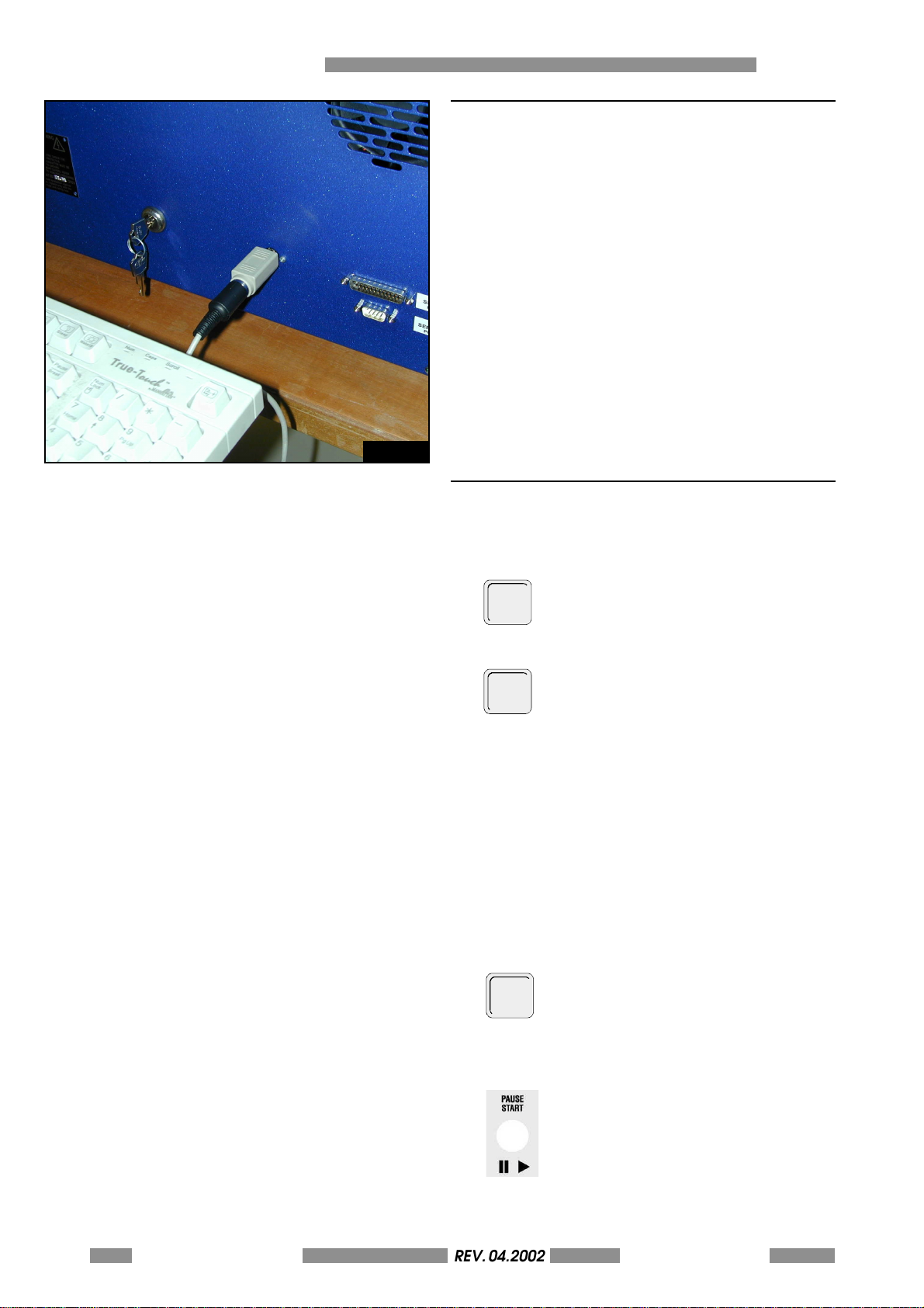
The machine is configured by accessing the
setup routine and setting or modifying various
parameters which are then saved permanently in
a CMOS memory inside the machine. To access
the setup routine connect a standard PC
keyboard to the DIN connector on the rear panel
of the machine.
Please, take care that a wrong setting of the
parameters may compromise the good
functioning of the machine.
In case of necessity, please refers to chapter A.11
to see how to restore the default value for each
parameter.
In case of impossibility in restoring or modify the
parameters, please call the service.
Fig. A.1
A.1 KEYBOARD DESCRIPTION
The following list describes the function keys and
their actions.
F10: This key is used to access the
F10
programming menu or other internal
functions of the machine. A Password
enables this command.
F3: This key enables the production of
F3
test cards with a pre determined format.
It is done without the aid of the computer.
Type in the number between 0 and 7
which corrisponds to the card tests desired
and then press ENTER to produce the
card.The list below describes the card
tests available.
0 Stamping all characters on the drum
1 Stamping an "L" in each angle of the card
5 Stamping a plate with all the machine setup
6 Stamping a text of type 1
7 Stamping of enabled logos
A-52 METAL DOT MATRIXREV. 04.2002
OPERATORS MANUAL
ESC: If this key is pressed the current
operating cycle will be halted and the
card will be unloaded.DUP If this key is
pressed during a READY state and it is
followed by ENTER the machine will
repeat the last card made.
PAUSE: If this key is pressed the current
operating cycle is blocked. Press START
to continue.
Page 53
START: Clears any error condition which
REV. 05-2008
may have occurred during the current
operating cycle and do not repeat the
card.
RETRY in case of error if it is pressed the
machine repeat the card.
THE MACHINE'S SETUP A
ENTER
ENTER: Ex ec ut e t he da ta
F5: This key selects the operational mode
F5
of the inserting cycle. It is used for tests
and there are 8 choices based on the
combinations of the following 3 modes.
- CONTINUOUS: METAL DOT MATRIX
repeats the last processed card
continuously.
- WITHOUT CARD: METAL DOT MATRIX
runs the operating cycle without
controlling for the presence of a card.
- PAUSE: METAL DOT MATRIX executes
each operation in response to the user
input The key to activate each
movement is START.
1. CONTINOUS
2. WITHOUT CARD
3. WITHOUT CARD & CONTINOUS
4. PAUSE
5. CONTINOUS & PAUSE
6. WITHOUT CARD & PAUSE
7. WITHOUT CARD - CONTINOUS & PAUSE
8. READY
The direction keys
are using to move the cursor in the menu.
REV. 04.2002METAL DOT MATRIX
OPERATORS MANUAL
A-53
Page 54
A THE MACHINE'S SETUP
ESC
REV. 05-2008
A.2 MENU DESCRIPTION
F10
Press
while in the READY state and type in
the password. Contact the local dealer for
information about the setup password.
A 7 row menu will appear on the display:
1. CONFIGURATION PARAMETERS
2. SERIAL INTERFACE
3. MECHANICAL PARAMETERS
4. PROTOCOLS
5. PASSWORD
6. STAMPING CONFIGURATION
7. KEYPAD LCD
The menu items can be selected using the arrow
keys and .
ENT ER
The
key confirms the choice and enters
into the selected items own menu.
The
key returns the operator to the
ESC
preceding menu.
Pressing
a second time terminates the
ESC
configuring of the machine. The machine leave
the setup and after few seconds come back in
power-on stand-by status.
An item can be modified by selecting it with the
numeric keys and confirming the choice with
ENTER
.
To exit from the setup mode press
key
untill the machine make a reset cycle and come
back to the ready state.
(11,15,3,6,12,24,48,96) (4800)
A-54 METAL DOT MATRIXREV. 04.2002
OPERATORS MANUAL
A.2.1 MODIFYING THE PARAMETERS
The typical parameter display screen is as follows:
CHOICE OF THE BAUD RATE
where:
CHOICE OF THE BAUD RATE = name of the
parameter
(11,15,3,6,12,24,48,96) = possible values
(4800) = current value
Page 55
To modify the value of the parameter displayed,
ESC
REV. 05-2008
on the keypad, press the number corresponding
to the position to the left of the value required
(the corresponding selection is displayed on the
left of the display unit beside the current value)
and then press 'Enter'.
Example: modifying the Baud rate in the Protocols
menu
To set a Baud Rate of 9600, do the following:
THE MACHINE'S SETUP A
- Press key
8
corresponding to the eighth
possible value (96), namely 9600. The left of
the display unit will display the corresponding
selection:
CHOICE OF THE BAUD RATE
(11,15,3,6,12,24,48,96) (4800) 9600
- Then press
- Press
ENT ER
to save the new value.
twice to quit set-up and apply the
modifications.
For parameters for which you can enter number
values, only the actual possible values are
indicated. In this case, on the keypad, type the
new value, making sure you specify the sign, if
required.
Specify the sign, if required, by typing
1
for
+
and
2
for
-
.
Example: modifying a mechanical parameter
To set a value of +04, do the following:
X TOTAL ADJ
(-99/+99) (+/- = 1/2) (00)
- Press
,
0
1
4
.
The display unit will display the new value.
X TOTAL ADJ
(-99/+99) (+/- = 1/2) (00) +04
- Press
ENTER
to confirm.
REV. 04.2002METAL DOT MATRIX
OPERATORS MANUAL
A-55
Page 56
A THE MACHINE'S SETUP
REV. 05-2008
A.3 GENERAL PROGRAMMING OF THE MACHINE
The structure of the main setup menu is described
below. To enter in setup mode do as follow:
From the initial state of the display
METAL DOT MATRIX 2000 V.Y.YY
READY
Press
F10
SETUP STAMPER
PASSWORD ?
Type the password and press
ENTER
.
By up and down arrow you can switch between
the following menu (refers to chapters A4-A10 for
the description of each of them):
CONFIGURATION PARAMETERS
Press the key
SERIAL INTERFACE
Press the key
MECHANICAL PARAMETERS
Press the key
Press the key
Press the key
STAMPING CONFIGURATION
PROTOCOLS
PASSWORD
A-56 METAL DOT MATRIXREV. 04.2002
OPERATORS MANUAL
Page 57
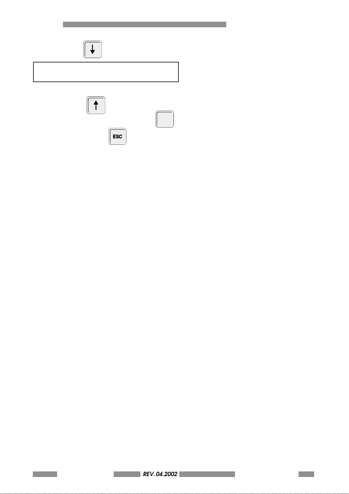
Press the key
REV. 05-2008
KEYP AD LCD
This is the last menu; to select another use the
direction keys
THE MACHINE'S SETUP A
To enter the menu items selected press
ENT ER
.
To exit the setup press
NOTE: The Setup program includes a keyboard
Timeout. After 2 minutes the machine will exit from
the setup menu and returns to the READY state.
REV. 04.2002METAL DOT MATRIX
OPERATORS MANUAL
A-57
Page 58
A THE MACHINE'S SETUP
ESC
REV. 05-2008
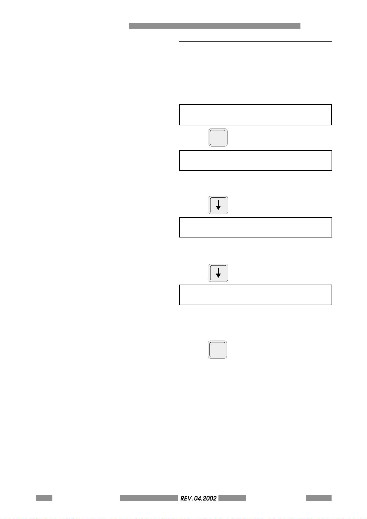
A.4 CONFIGURATION PARAMETERS
The configuration parameters menu enables the
setting of the following general parameters of
the machine.
The parameters of the menu are described below:
Choose this menu.
CONFIGURATION PARAMETERS
ENTER
Press
UNLOADER FULL ALARM
(YES/NO)
YES: selection cause the block of the machine
when the unloader unit is full.
Press
PUSHER HOME
(YES/NO)
YES: after each feed of the card the pusher come
back to the home position.
Press
CARD ERROR REPETITION
(0-9) (0)
Number of retry in reproducing the card in case
of errors.
Press
t w i c e t o t e r m i n a t e t h e s e t u p a n d t o
return to the READY state.
A-58 METAL DOT MATRIXREV. 04.2002
OPERATORS MANUAL
Page 59
A.5 SERIAL PORT PROGRAMMING
REV. 05-2008
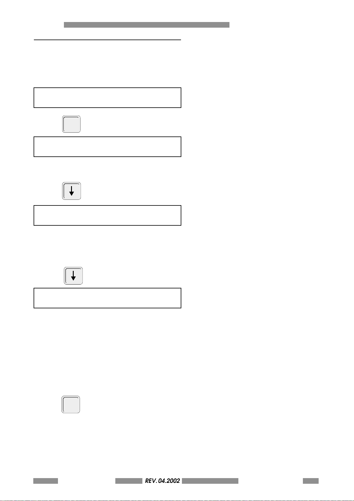
The Serial Interface menu enables the configuring
of the machines serial port.
Choose the desided menu:
SERIAL INTERFACE
ENTER
Press
BITS PER CHARACTER
(7,8) (7)
1 Selects 7 bit for chars
2 Selects 8 bit for chars
Press
THE MACHINE'S SETUP A
PARITY
(NO,OD,EV) (EV)
1. NO Selects No Parity
2. OD Selects Odd Parity
3. EV Selects Even Parity
Press
CHOICE OF THE BAUD RATE
(11,15,3,6,12,24,48,96) (4800)
1 Selects 110 Baud Rate.
2 Selects 150 Baud Rate.
3 Selects 300 Baud Rate.
4 Selects 600 Baud Rate.
5 Selects 1200 Baud Rate.
6 Selects 2400 Baud Rate.
7 Selects 4800 Baud Rate.
8 Selects 9600 Baud Rate.
Press
t w i c e t o t e r m i n a t e t h e s e t u p a n d t o
ESC
return to the READY state.
REV. 04.2002METAL DOT MATRIX
OPERATORS MANUAL
A-59
Page 60
A THE MACHINE'S SETUP
ESC
REV. 05-2008
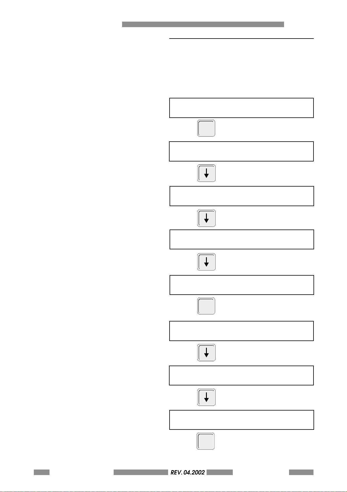
A.6 MECHANICAL PARAMETERS ADJUSTMENT
This menu permits to adjust some mechanical
parameters of the machine. The value are setted
by the CIM quality control check before putting
the product on the market.
The parameters of the menu are described below:
Choose this menu:
MECHANICAL PARAMETERS
ENTER
Press
X TOTAL ADJ
(- 99 / + 99) (00)
Press
X STAMP ADJ
(- 99 / + 99) (00)
Press
Y STAMP ADJ
(- 99 / + 99) (00)
Press
Y LOAD ADJ
(- 99 / + 99) (00)
ENTER
Press
Y UNLOAD ADJ
(- 99 / + 99) (00)
Press
Y PUSHER LOAD ADJ
(- 99 / + 99) (00)
A-60 METAL DOT MATRIXREV. 04.2002
OPERATORS MANUAL
Press
X UNLOADER ADJ
(- 99 / + 99) (00)
Press
t w i c e t o t e r m i n a t e t h e s e t u p a n d t o
return to the READY state.
Page 61
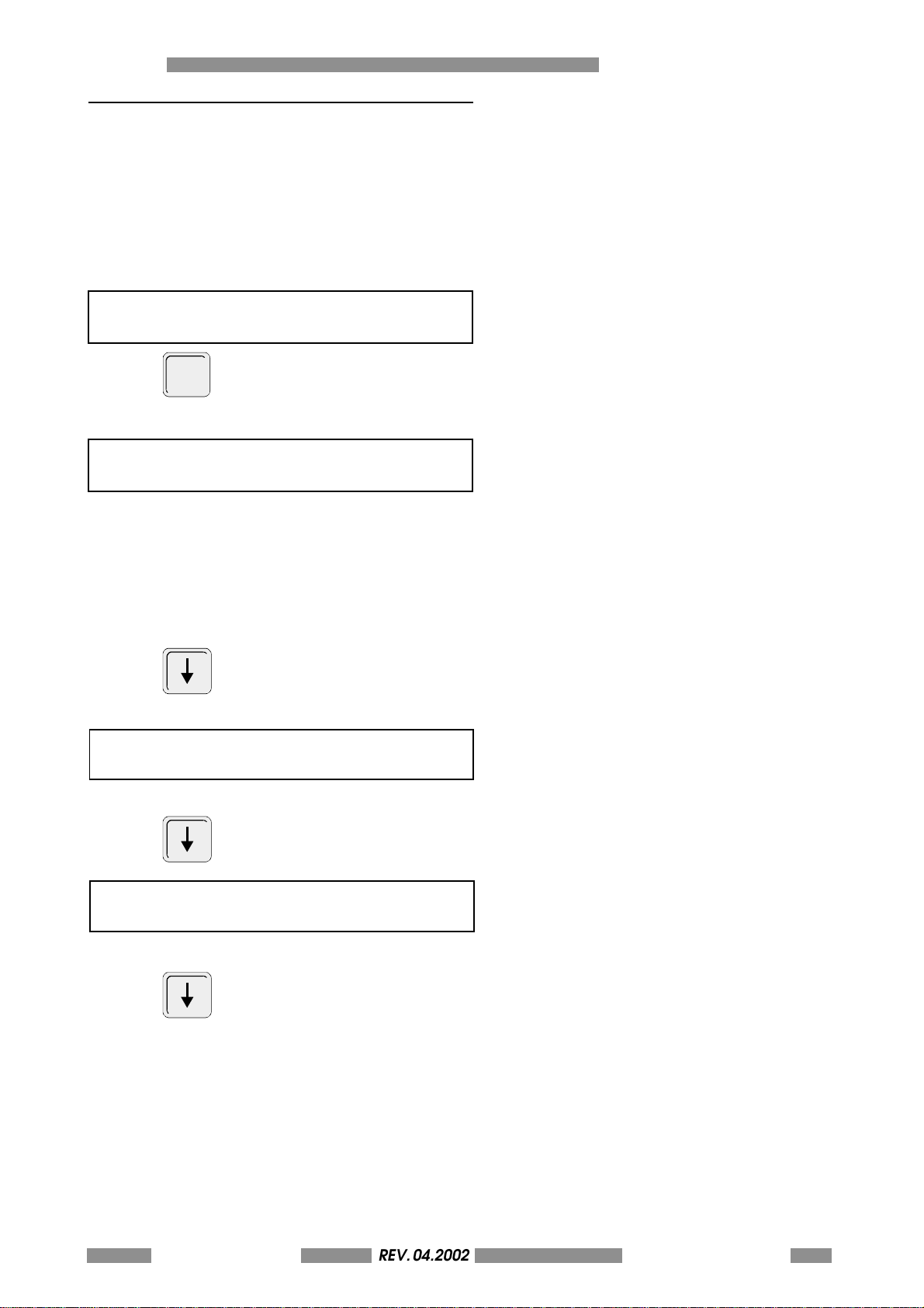
A.7 PROTOCOLS SETTINGS
REV. 05-2008
This menu permits to customize the value of the
typical parameters of the comunication between
machine and pc. in particular, if a comunication
protocol which differs from the default is to be
used, it will be necessary to modify this setup.
The parameters of the menu are described below:
Choose this menu.
PROTOCOLS
ENTER
Press
The following list of Protocols are displayed.
CHOISE OF THE PROTOCOL (CIM)
(CIM, XON, MUL)
THE MACHINE'S SETUP A
Using the numeric keys and choose the
corrisponding Protocols
1 selects the protocol CIM
2 selects the protocol XON-XOFF
3 selects the protocol MULTI EMBOSSER
Press
START OF THE TEXT
SELECTION (000-121) (002) STX
the value of Start of Text (002-STX-Start of Text).
Press
END OF TEXT
SELECTION (000-121) (003) ETX
the value of End of Text (003-ETX-End of Text).
Press
REV. 04.2002METAL DOT MATRIX
OPERATORS MANUAL
A-61
Page 62
A THE MACHINE'S SETUP
REV. 05-2008
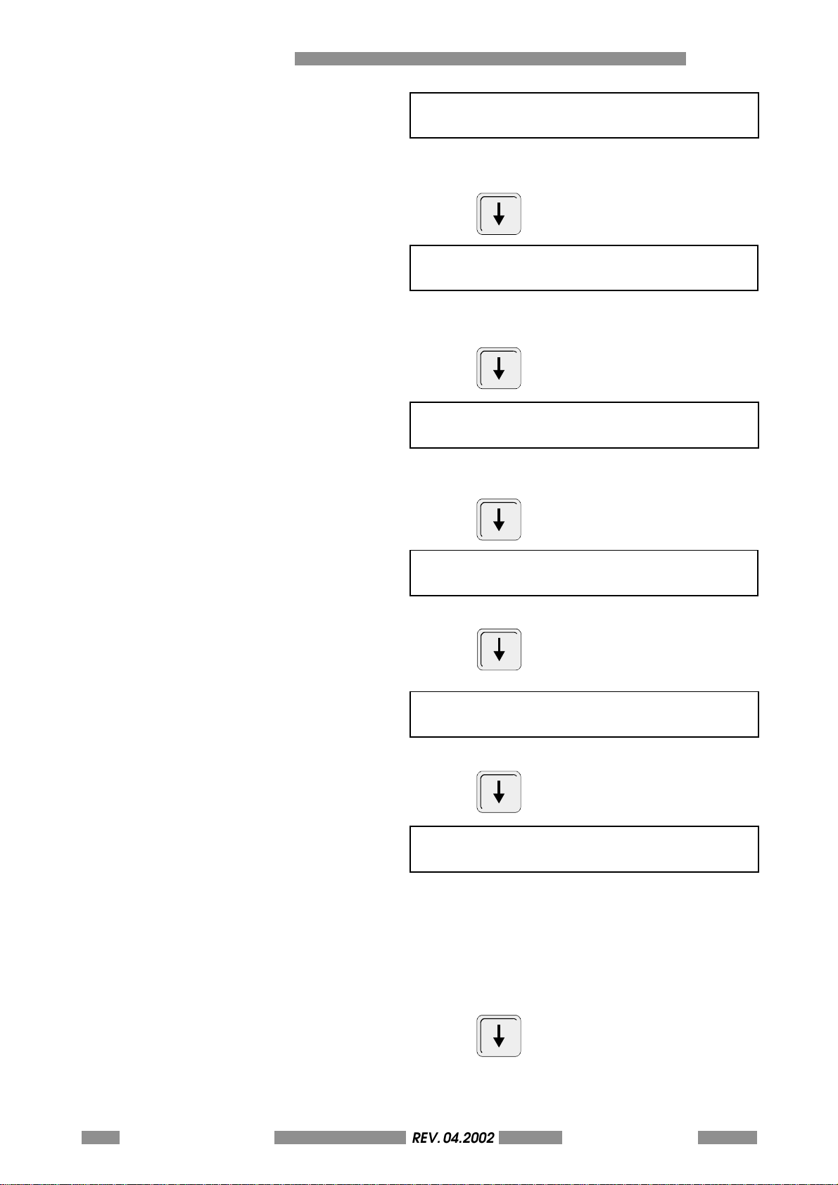
FIELD SEPARATOR
SELECTION (000-121) (013) CR
the value of Field Separator (013-0D hex-CRCarriage Return).
Press
US PROTOCOL OCR OPENER
SELECTION (000-121) (040) (
the value us protocol OCR opener used on
protocols USA only.
Press
US PROTOCOL OCR CLOSER
SELECTION (000-121) (041) )
the value us protocol OCR closer used on protocols
USA only.
Press
MULTILOAD OPENER
SELECTION (000-121) (014) S0
the value of multiload.
Press
MULTI ADDRESS
SELECTION (00-88) (31)
the value of multi address
Press
NORM/BLOC
SELECTION (1/2) (NORM)
NORM With XON/XOFF protocol the interchar
and interline spacing are fixed to the
default in firmaware value.
BLOC The interline and intercharacter spacing
may be changed by means of "bloc char
spacing" and "bloc line spacing"
parameters
A-62 METAL DOT MATRIXREV. 04.2002
OPERATORS MANUAL
Press
Page 63
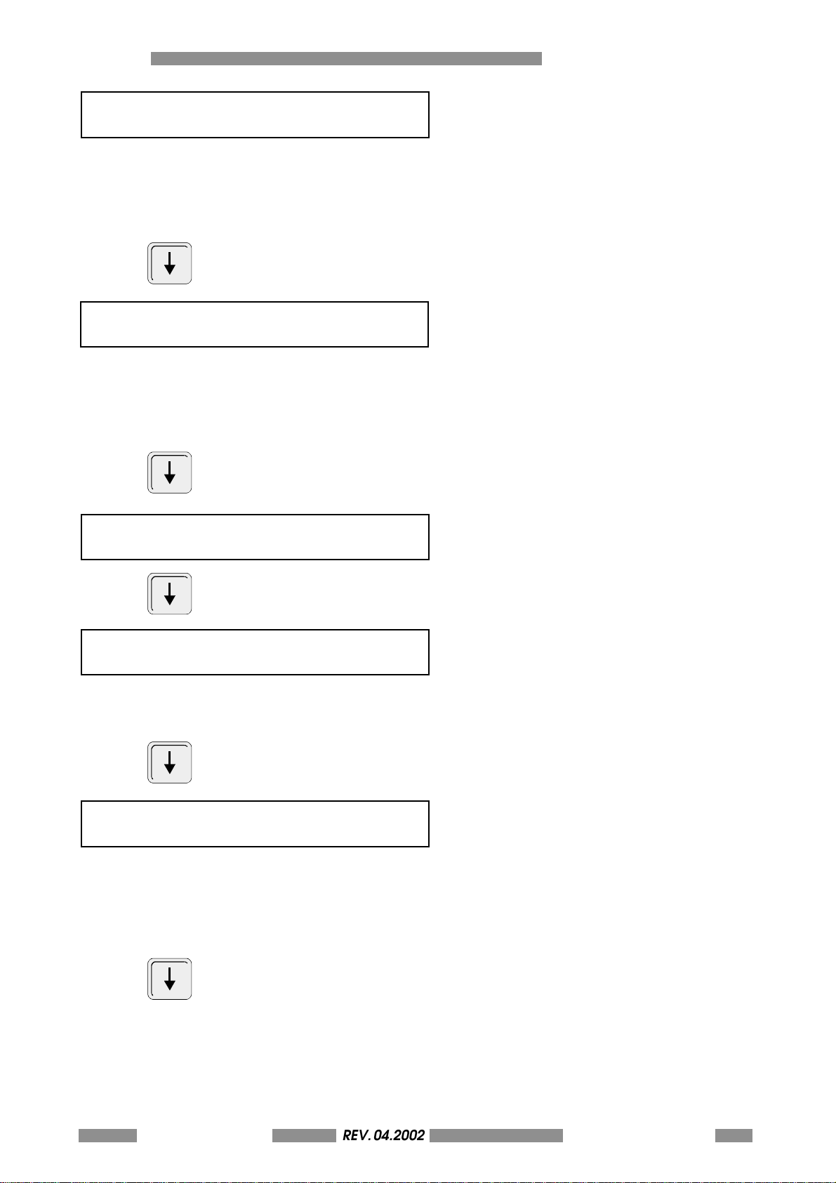
BLOC CHAR SPACING
REV. 05-2008
SELECTION (015-058) (32)
This parameter permits to modify the interchar
spacing used by XON/XOFF protocol and card
test. The value represunts the number of step of
the motor.
A c t i v e o n l y w h e n N O R M / B L O C i s s e t t e d a s B L O C .
Press
BLOC LINE SPACING
SELECTION (016-080) (48)
This parameter permits to modify the interline
spacing used by XON/XOFF protocol and card
test. The value represunts the number of step of
the motor.
A c t i v e o n l y w h e n N O R M / B L O C i s s e t t e d a s B L O C
THE MACHINE'S SETUP A
Press
PLATE HEIGHT (MM)
SELECTION (020-090) (054)
Press
CIMLIKE FUNCTION
SELECTION (000-127) (NO)
The value of the Opener Format in the CIMLIKE
protocol. The value 000 (NO) for protocol CIM
Standard
Press
CIM MULTIBUFFER
(ON/OFF) (OFF)
Enable "spooling" mode:
with multibuffer= on all the date of the plate you
have to print sholud be sent fron the PC to the
machine before the execution of the first card
(not available with software Sword)
Press
REV. 04.2002METAL DOT MATRIX
OPERATORS MANUAL
A-63
Page 64
A THE MACHINE'S SETUP
REV. 05-2008
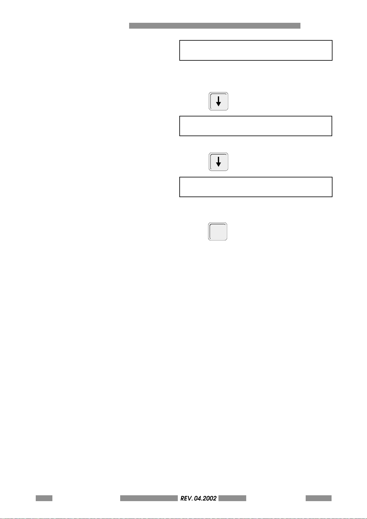
PRESENCE LINE FEED
(YES/NO) (NO)
YES: filed separator = CRLF (if field separator =
CR)
NO: field separator = CR (if field separator = CR)
Press
XON
SELECTION (000 -127) (017) XON
Set the character with meaning af XOFF
Press
XOFF
SELECTION (000 -127) (019) XOFF
Setting of character with meaning of XOFF
Press
t w i c e t o t e r m i n a t e t h e s e t u p a n d t o
ESC
return to the READY state.
A-64 METAL DOT MATRIXREV. 04.2002
OPERATORS MANUAL
Page 65
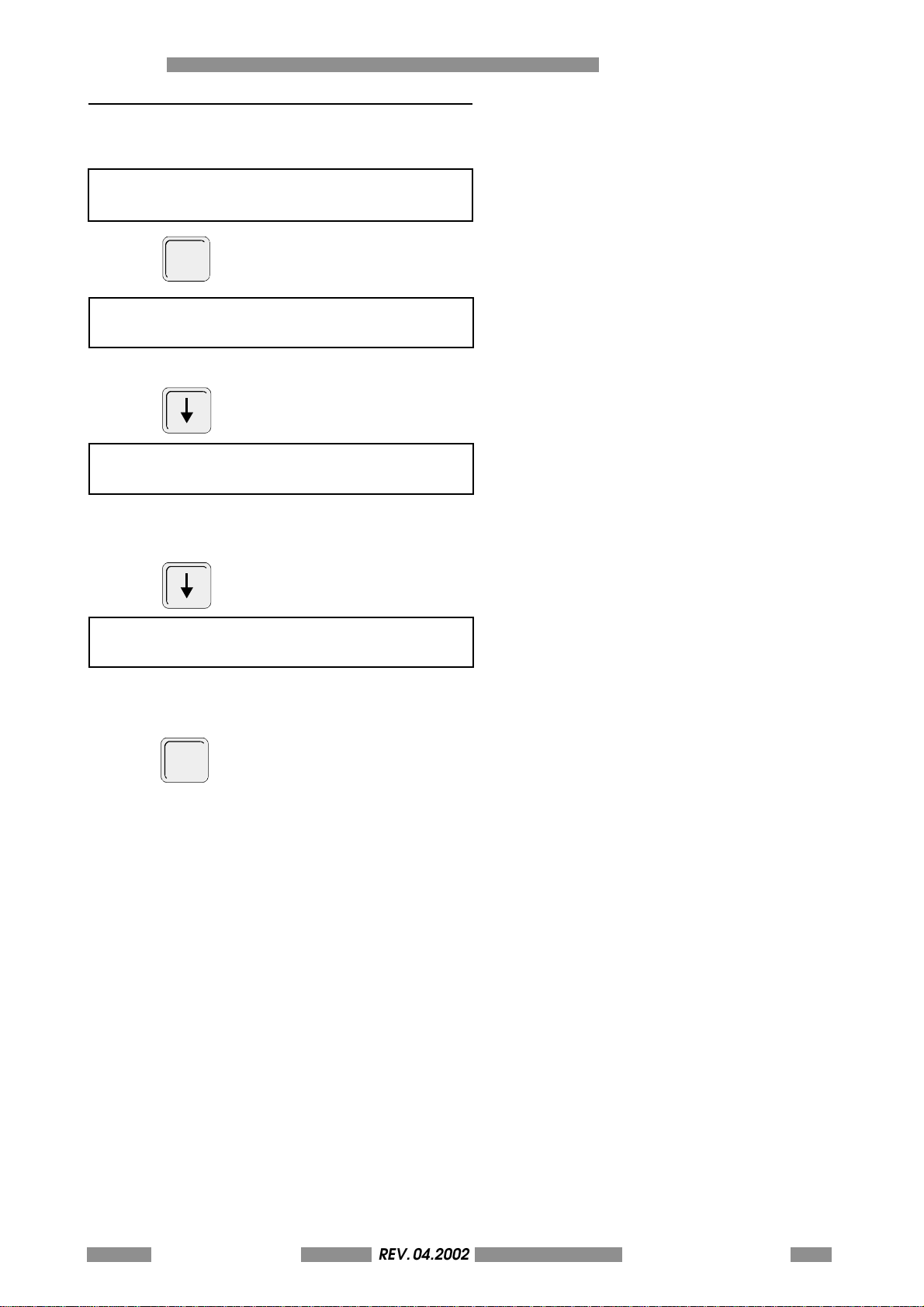
A.8 PASSWORD
REV. 05-2008
Choose this menu
PASSWORD
ENTER
Press
PASSWORD ENABLE
(ON/OFF) OFF
Select ON to define a password for setup access.
Press
USER PASSWORD (????)
NEW VALUE:
THE MACHINE'S SETUP A
(only if password enabed = ON)
Enter the password (only numeric characters)
Press
SERIAL NUMBER (DEFAUL VALUE)
NEW VALUE:
Enter new serial number.
Press
t w i c e t o t e r m i n a t e t h e s e t u p a n d t o
ESC
return to the READY state.
REV. 04.2002METAL DOT MATRIX
OPERATORS MANUAL
A-65
Page 66
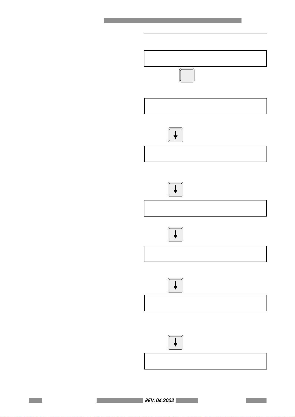
A THE MACHINE'S SETUP
REV. 05-2008
A.9 STAMPING CONFIGURATION
Choose this menu
STAMPING CONFIGURATION
and press
ENTER
The following parameters are displayed
COORDINATES OF STAMPING
(INCHS/MILLM) (MILLM)
Format coordinate selection
Press
FONT SIZE
(010%-300%) (100%)
Size adjustment of the stamped font referred to
the size of the resident font
Press
LOGO ENABLE
(BOTH,LOGO1, LOGO2, NONE) (NONE)
Enabled logos for stamping
Press
LOGOS COORDINATES ACQUISITION
(LOGO/SETUP) (LOGO)
Set the logo's coordinates data source from logo
(bitmap) or setup (from lower - left corner)
Press
LOGO 1 X COORDINATE
(0000-1220) (0000)
Set the X coordinate of logo 1 (1=0,1 mm).
Available only if the "LOGOS COORDINATES
ACQUISITION" parameter is set as "SETUP"
Press
LOGO 1 Y COORDINATE
(0060-0880) (0060)
A-66 METAL DOT MATRIXREV. 04.2002
OPERATORS MANUAL
Set the Y coordinate of logo 1 (1=0,1 mm).
Available only if the "LOGOS COORDINATES
ACQUISITION" parameter is set as "SETUP"
Page 67
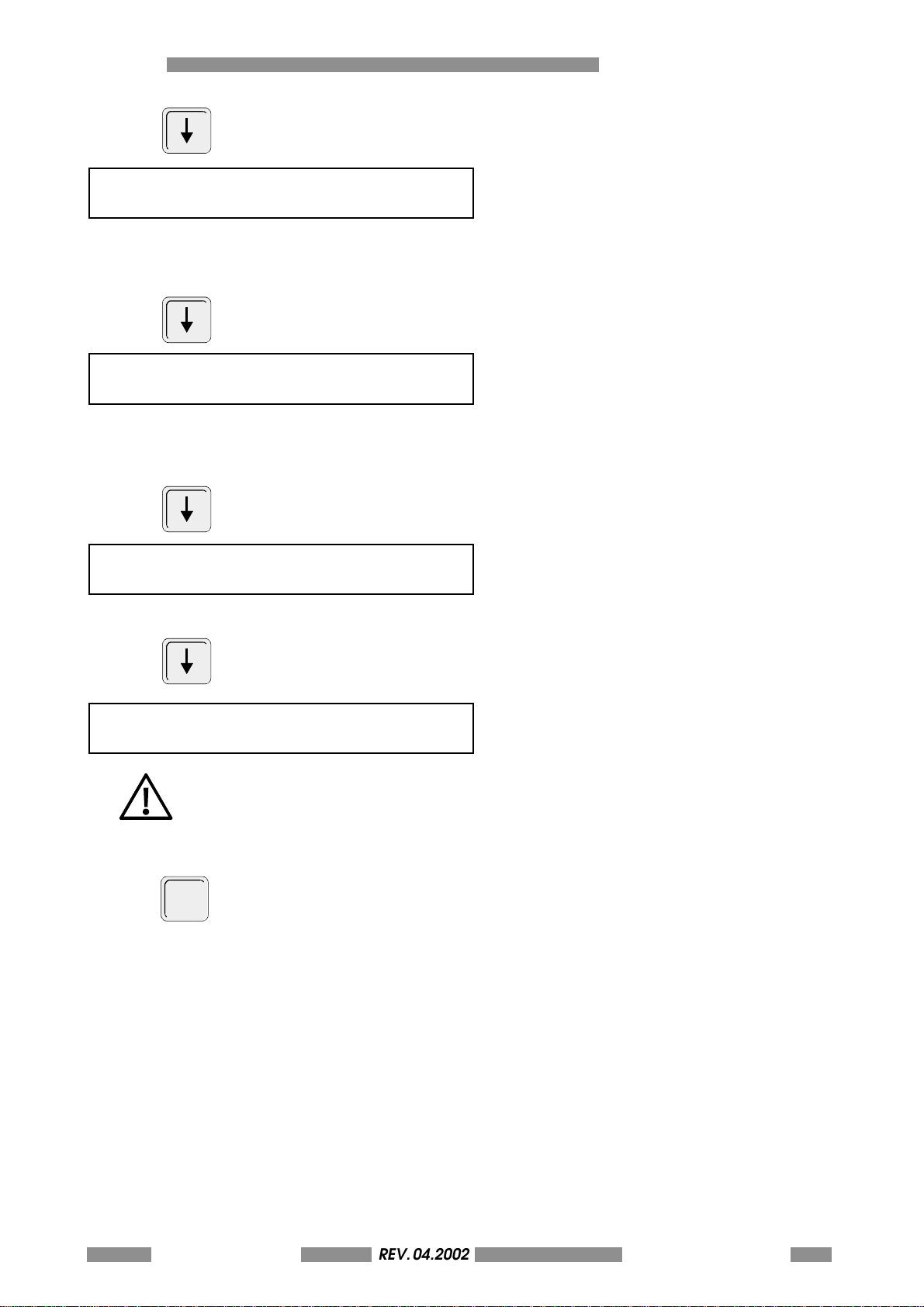
Press
REV. 05-2008
LOGO 2 X COORDINATE
(0060-0880) (0060)
Set the X coordinate of logo 2 (1=0,1 mm).
Available only if the "LOGOS COORDINATES
ACQUISITION" parameter is set as "SETUP"
Press
LOGO 2 Y COORDINATE
(0060-0880) (0060)
Set the Y coordinate of logo 2 (1=0,1 mm).
Available only if the "LOGOS COORDINATES
ACQUISITION" parameter is set as "SETUP"
Press
THE MACHINE'S SETUP A
LOGO ROTATION
(0-90-180-270) (0)
Set the logo rotation in degrees
Press
STAMPING FORCE
(050-090) (065)
Frequency of stylus vibration.
Don't modify the default value
Press
t w i c e t o t e r m i n a t e t h e s e t u p a n d t o
ESC
return to the READY state.
REV. 04.2002METAL DOT MATRIX
OPERATORS MANUAL
A-67
Page 68
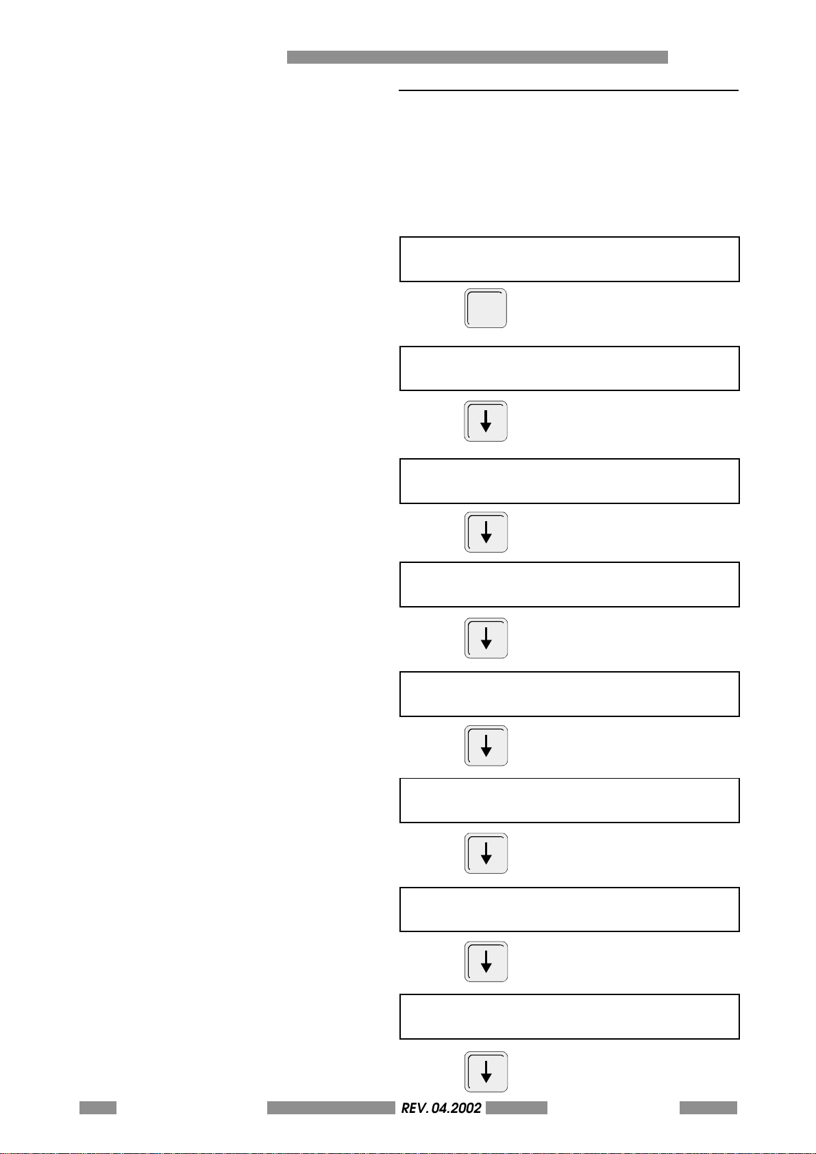
A THE MACHINE'S SETUP
REV. 05-2008
A.10KEYPAD LCD SETTING
This menu permits to enable or disable some keys
of the keyboard in order to inhibit some function
to the operator. Please note that inhibit of some
key may cause the impossibility to restore old
values.
Choose this menu
KEYPAD LCD
Press
ENTER
ENABLE KEY RETRY
(ON/OFF) (ON)
Press
ENABLE KEY START
(ON/OFF) (ON)
Press
ENABLE KEY DUP
(ON/OFF) (ON)
Press
ENABLE KEY ENTER
(ON/OFF) (ON)
Press
ENABLE KEY ABORT
(ON/OFF) (ON)
Press
ENABLE KEY CARD TEST
(ON/OFF) (ON)
Press
ENABLE KEY STAMP MODE
(ON/OFF) (ON)
Press
A-68 METAL DOT MATRIXREV. 04.2002
OPERATORS MANUAL
Page 69
ENABLE KEY PAUSE
REV. 05-2008
(ON/OFF) (ON)
Press
FUNCTION OF KEY START AFTER ERROR
(ABORT/RECOVERY) (ABORT)
THE MACHINE'S SETUP A
Press
t w i c e t o t e r m i n a t e t h e s e t u p a n d t o
ESC
return to the READY state.
REV. 04.2002METAL DOT MATRIX
OPERATORS MANUAL
A-69
Page 70
A THE MACHINE'S SETUP
REV. 05-2008
A.11RESET OF PARAMETERS
Sometimes electrical disturbs could modify the
value of critical parameters causing errors and
malfunctions of the machine.
Following this procedure all the parameters are
resetted to the default values and many broblems
could be solved.
Type
SET UP
in sequence
to reset all the setup.
Type
SET UP
STAMP
MODE
STAMP
in sequence
MODE
to reset the configuration parameters.
ATTENTION: After this operation you have to
manually restore all the paremeters that you can
find in the sample cards attached to the machine
(see chap. A4-A10 to know how to modify the
parameters).
A-70 METAL DOT MATRIXREV. 04.2002
OPERATORS MANUAL
Page 71
A.12 DISPLAYING THE COUNTERS
REV. 05-2008
The statistical data of the production is available
i n t h e p a r t i a l a n d t o t a l c o u n t e r s . T h e l a t t e r c a n n o t
be modified. The values indicate the total number
of operating cycles without error.
Running the command sequence
ENT ER
1
.
F10
METAL DOT MATRIX 2000 V.Y.YYY
CNT=0000000001 TOTAL =0000000001
• The left value is the partial counter for the
operator.
• The right value is the total counter
THE MACHINE'S SETUP A
Running the command sequence
ENT ER
0
.
The partial counter is Reset.
F10
REV. 04.2002METAL DOT MATRIX
OPERATORS MANUAL
A-71
Page 72
A THE MACHINE'S SETUP
REV. 05-2008
A.13 CARD TEST LIST
To make a card test connect the keyboard to the
rear DIN connector and select the mode
(continous, without card, ) by means of the F5
key.
Then press the key F3 and the number of the card
test (see the list below) and press Enter.
The card test presently available for METAL DOT
MATRIX models are shown in the following table.
0 Stamp all characters
1 Stamp an "L" in each angle of the card
5 Stamp a plate with all the machine setup
6 Stamp a CIM fixed text
7 Stamp enabled logos (see the STAMPING
CONFIGURATION menu to see how to enable
the logos for stamping)
Note: with regard to the Card Tests 0, 5 and 6, the
intercharacter and interline spaces depend to
the value of the setup parameters BLOC CHAR
SPACING and BLOC LINE SPACING of the protocol
menu.
A.14RESET OF THE MACHINE
To reset the machine in each moment press the
following key sequence:
F10
.
A-72 METAL DOT MATRIXREV. 04.2002
OPERATORS MANUAL
Page 73
METAL DOT MATRIX
HOW TO UPDATE THE FW ANNEX B
B-73
Page 74
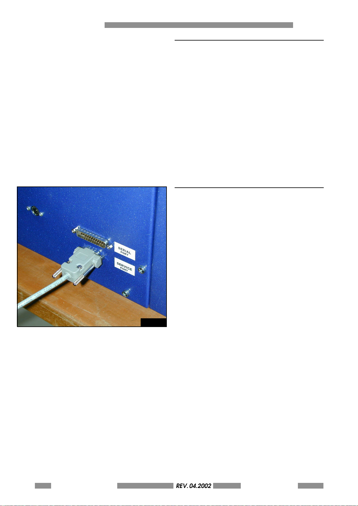
B HOW TO UPDATE THE FW
REV. 05-2008
B.1 INTRODUCTION
The new METAL DOT MATRIX and Metal Dot
Matrix series permits to easy upgrade the fw in
order to give to the customers a product always
adjourned.
B.2 CONNECTION PROCEDURE
Fig. B.1
If you have to update the "FIRMWARE" for the
machine, do the following:
Connect the serial cable of your PC to the
"SERVICE PORT" of the machine.
B-74 METAL DOT MATRIXREV. 04.2002
OPERATORS MANUAL
Page 75

B.3 SOFTWARE
REV. 05-2008
The "CIM_BIOS.EXE" DOS utility, available on the
manual CD-ROM in the "Tools" directory, handles
the communication with the BIOS for
programming the Flash.
Launch the "CIM_BIOS" command without
parameters to access a "help" section for the
utility.
NOTE: CIM_BIOS.EXE REQUIRES A PC
WITH WIN 95, WIN 98 OR WIN
MILLENNIUM OPERATING SYSTEMS. IF
THE OPERATING SYSTEM IS
DIFFERENT, USE A DOS BOOT DISK TO
RUN THE PC IN DOS MODE.
The command line for the call is as follows:
CIM_BIOS FileName Port TransmissionType
BaudRate.
FileName: Specifies the name of the source file
containing the data to be transferred to the
machine.
Port: S pe ci f ie s t he a s e ri a l p o rt o n t h e P C us e d f or
the connection(COM1, COM2, ).
TransmissionType: Letter which specifies the type
of function required.
U: Machine code
updating................................ (new firmware)
B: Machine Bios updating ............ (Do not use)
E: Flash FW and Data deletion .... (Do not use)
P: Machine Parameter Sending .. (Do not use)
J: Internal Layout Sending ........... (Do not use)
Q: Machine parameter file
request ....................................... (Do not use)
L: Front side Logo
sending .......... (New resident Logo1 see B.5)
M: Back side Logo sending
..................................... (New resident Logo2)
F: Font 1 sending........................... (Do not use)
G: Font 2 sending ................ (Not implemented)
H: Font 3 sending ................ (Not implemented)
I: Font 4 sending................ (Not implemented)
HOW TO UPDATE THE FW B
BaudRate: number between 1 and 5 which
specifies the transmission speed (always use 4,
which corresponds to a transmission speed of
57600 Baud).
METAL DOT MATRIX
REV. 04.2002
OPERATORS MANUAL
B-75
Page 76
B HOW TO UPDATE THE FW
REV. 05-2008
B.4 FIRMWARE UPDATING PROCEDURE
- Copy the CIM_BIOS.EXE program and the
firmware file (e.g. V4010601.hex) into a single
directory (or to the floppy disk root).
- Run the PC in DOS mode or use the Windows
command "Prompt".
- With the machine OFF, at the DOS "prompt",
type the command line with the required
parameters (e.g.: cim_bios V4010601.hex
com1 U 4). The program will wait for a
synchronism character.
- While cim_bios is waiting for a synchronism
character, turn ON the machine: the
"download" will start automatically. The PC
will display the progress of the "download".
- When the "download" is complete, the new
firmware can be used immediately.
- Look at the number of the FW version shown
on the display to verify that the update is
complete. If required, turn the machine OFF
and back ON again.
N.B. DO NOT TURN OFF THE MACHINE
DURING THE DOWNLOAD.
B.5 CHANGE RESIDENT LOGOS AND FONT PROCEDURE
To know how to change resident logos and fonts
refers to the software SWORD application manual.
B-76 METAL DOT MATRIXREV. 04.2002
OPERATORS MANUAL
Page 77
METAL DOT MATRIX
LCD EDIT ANNEX C
C-77
Page 78
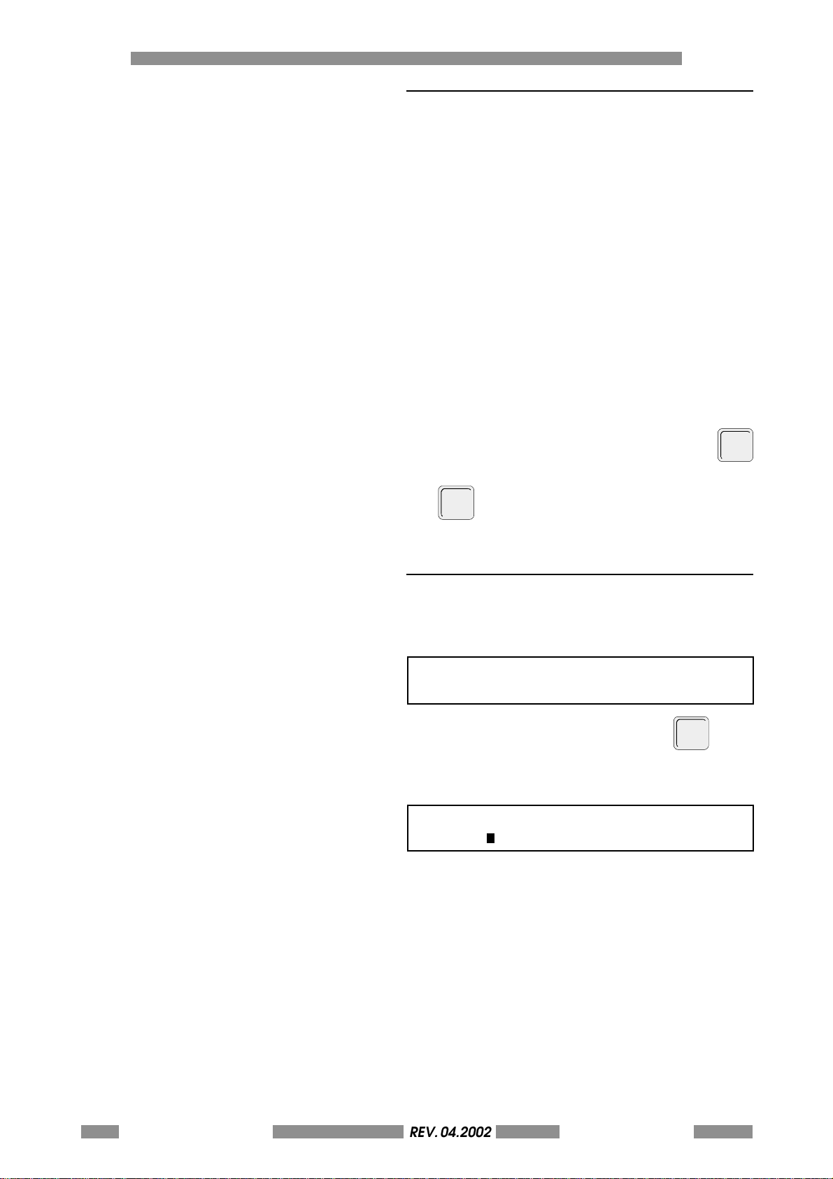
CLCD EDIT
REV. 05-2008
C.1 LCD EDIT AVAILABILITY
Stampers equipped with an external keyboard
have an off-line stamping capaiblity ('LCD Edit')
i.e. the stamping data is entered from that
keyboard and does not come from a connected
computer. The operator may create and store
formats and enter card data using the keyboard.
The formatting procedure is discussed in Section
2.
The LCD edit ( off-line ) mode does not depend
on a Host Computer connection.
A format must be created and stored before
data entry is possible. See Section 2 on LCD edit
format creation and storage. All formats can be
given a name of up to 8 characters in length. The
first format ( primary format ) '01' is a default
format. This format will be selected automatically
when the LCD edit function is requested for the
first time after switching on by pressing the
key. Any format can be selected by using the
F4
key followed by the format #, followed by
the Enter key two times.
C.2 ENABLING THE OFF-LINE MODE
An stamper, which is ready for off-line data, will
show the folllowing message on the LCD display:
V X.XX
READY
To enable the off-line option, press
F7
The LCD messages will be displayed:
FORMAT: 01 NAME: ADMIT F7 TO ON-LINE
ACCT #:
F7
.
C-78 METAL DOT MATRIXREV. 04.2002
OPERATORS MANUAL
Data can be entered to the first field of the format
01.
Detailed information is given on Page 4,
Reference: Stamp Data Entry.
Page 79
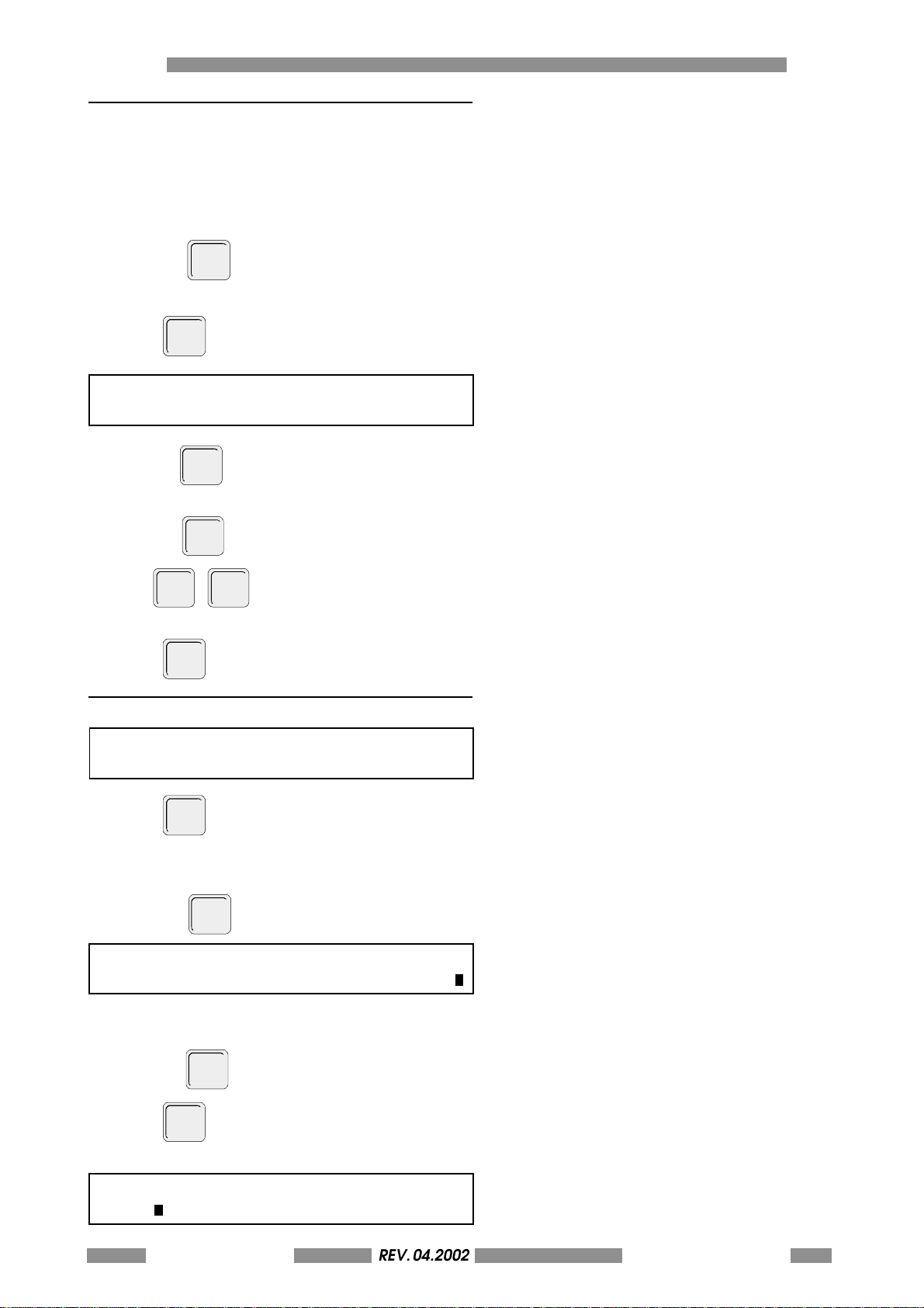
C.3 FORMAT MENU
ENTER
ENTER
REV. 05-2008
The twenty formats stored in the stamper are
as s i gn e d a t w o di g it n u mbe r , 00 - 19 . Eac h for m at
can be assigned a name of up to 8 digits during
the formatting procedure.
A format menu can be displayed on the LCD by
LCD EDIT C
F2
F2
.
.
pressing
Press
FM: 00 NAME: ADMIT FM: 01 NAME: EMER
FM: 02 NAME: EMPLOY FM: 03 NAME: OPEN
ENTER
Use the
key to move the cursor to the next
format.
SHIFT
TAB
key to skip to the next line.
TAB
-
to return to the last formatted
Use the
Use
line.
Press
F2
to return to the main menu.
C.4 FORMAT CHANGE
S=SELECT E=EDIT D=DELETE
FORM NO:00 FORM NAME:ADMIT SELECT:S
Press
F4
, Format # desired and Enter.
Example:
Select format 01
Press 01,
S=SELECT E=EDIT D=DELETE
FORM NO:01 FORM NAME:ADMIT SELECT:S
The cursor is now on the function 'SELECT '. See
Figure LCD-6
Pressing
ENTER
Press
will select the format.
One of the following two screens will be displayed:
FORMAT:01 FORMAT NAME: EMER F7 TO ON-LINE
ACCT#:
METAL DOT MATRIX
REV. 04.2002
OPERATORS MANUAL
C-79
Page 80
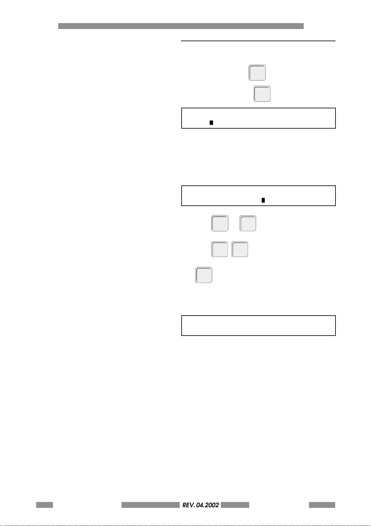
CLCD EDIT
REV. 05-2008
C.5 STAMP DATA ENTRY
Data can be entered for the first field. When
completed, press
Example: 123456-7,
ENTER
ENTER
.
.
ACCT#: 123456-7
NAME#:
Data can be entered for the second field, for the
third field etc.
The format may have fields programmed with a
counter or protective data. Data cannot be
entered into these fields, however the Enter must
be pressed to go to the next field.
NAME#:BOZZIEN GABRIELLE
HOSP#:BROOKDALE HOSP
Press
Press
ENT ER
SHIFT
or
TAB
for the next field.
TAB
to return to the last field.
F10
can be pressed at anytime to emboss.
If Enter or Tab is pressed when in the last field the
LCD will display the following:
THE LAST FIELD WAS COMPLETED PRESS:
F10 TO EMBOSS OR SHIFT TAB TO COME BACK
C-80 METAL DOT MATRIXREV. 04.2002
OPERATORS MANUAL
Page 81
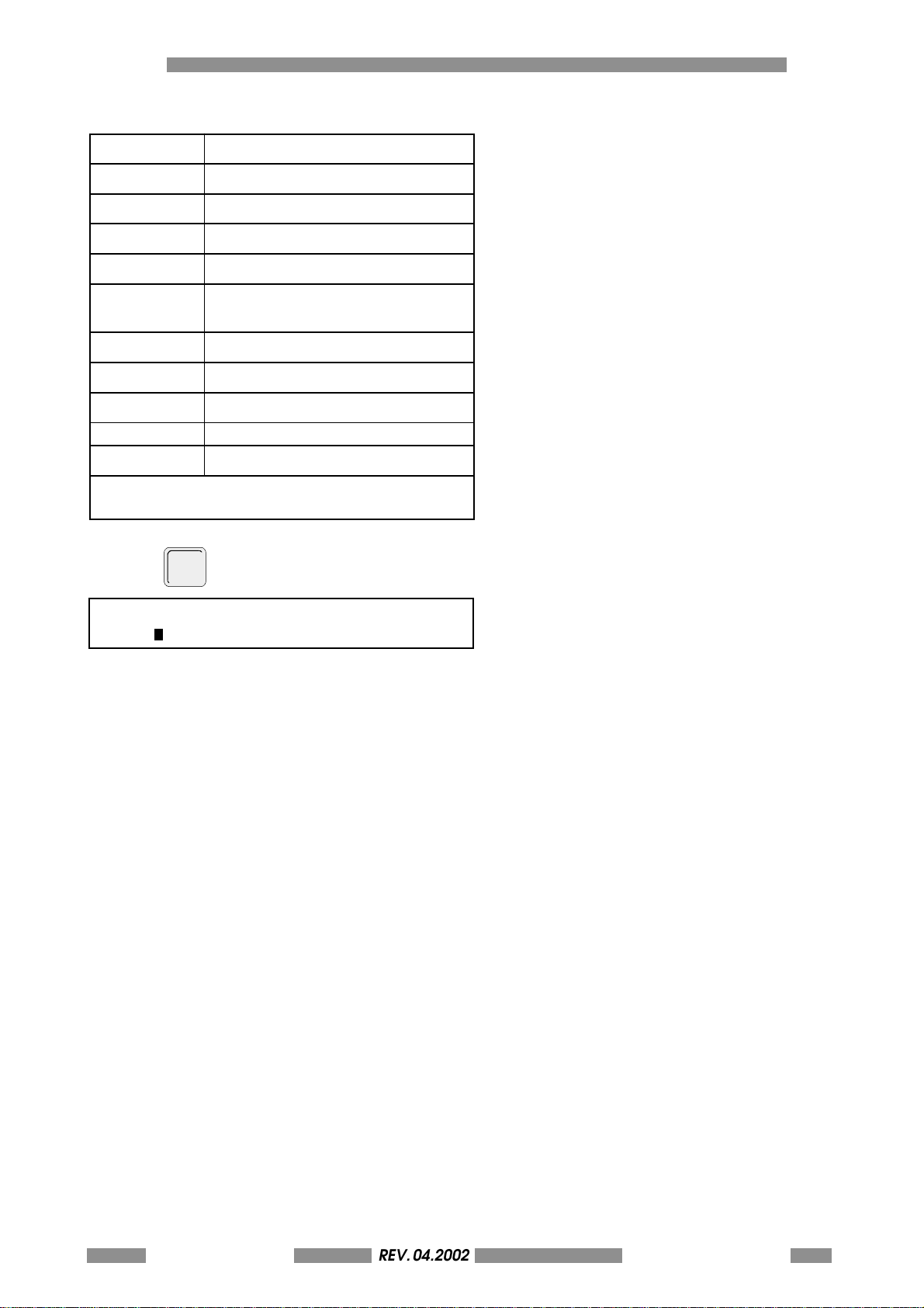
Function Key Summary:
REV. 05-2008
KEY PRESSED CONSEQUENT ACTION
ENTER GO TO NEXT FIELD
TAB GO TO NEXT FIELD
F7 EXITS THE LCD EDIT FUNCTION
SHIFT TAB RETURNS TO THE LAST FIELD (F5)
F1 RECALLS THE LAST EMBOSSED
CARD
F2 THE FORMAT MENU
F4 OTHER FORMATS
F10 EMBOSS
⇐⇐
⇐ MOVE CURSOR LEFT
⇐⇐
⇒ MOVE CURSOR RIGHT
DO NOT USE END, PG-DN, PG-UP, HOME OR INS
KEYS.
LCD EDIT C
F10
Press
to emboss
FORMAT: 01 FORMAT NAME: EMER F7 TO ON-LINE
ACCT#:
The card will be embossed.
METAL DOT MATRIX
REV. 04.2002
OPERATORS MANUAL
C-81
Page 82
CLCD EDIT
REV. 05-2008
C.6 EDIT STAMPED CARDS
The data of the last card embossed can be
recalled by pressing
F1
. New data can
overwrite the previous data. This includes all
fields even if the fields have protected data.
The data of the last card of all the formats is
saved. The data of the last card embossed of any
format can be recalled by pressing
F1
#,
.
F4
, Format
Data can be changed, this includes any protected
data. This edited card can then be embossed by
pressing
F10
. The second time
F1
is pressed
or the stamping of the edited message, will return
the system back to the original off-line data entry
mode.
If an error condition occurs the stamper' s LCD
will display the problem and the action to be
taken by the operator. The section on display
messages and keypad operations in Section 2 of
this manual will give further information on
messages and operator intervention.
C-82 METAL DOT MATRIXREV. 04.2002
OPERATORS MANUAL
Page 83

C.7 FORMATS - GENERAL
REV. 05-2008
Stampers can store in resident memory up to 20
formats with up to 26 fields of information in each
format. Data is entered to these formats using a
keyboard for off-line stamping
- described in Section 1 of this manual - and / or
through the RS232 line using the Stored Format
Protocols as described in Section IX of the 2500
Technical Operators Manual.
Format Variables
Formats can be designed and programmed by
the operator. Every format can be designed
individually with many options. it is important to
lay out these options before creating any format.
The options and variables for formatting are:
A Selection of 1 to 26 fields of information.
B Selection of character spacing for each field.
C Selection of the location of the fields on the
card (X and Y coordinates).
D Selection of type of numeric character
(Standard or OCR).
E Selection of incremental counters.
Up to 4 different counters per format.
(Increment or Decrement of steps of 1 to 9).
F Selection of incremental counters for
duplicated cards and duplicated fields.
G There are three modulus check digit algotithms,
Mod 10 Luhn, Mod 11 Continuous, and Mod
11 Non-continuous for both on-line and offline modes.An on-line check digit is calculated
and entered by the stamper. Off-line (LCD
E d i t ) , t h e o p e r a t o r m u s t e n t e r t h e p r o p e r c h e c k
digit.
H Programming of protected data which will
always be in the format.This is fixed repetitive
information.
I Field duplication: This eliminates the need to
re-enter the same data when it is repeated
elsewhere on the card.
L Selection of the number of duplicate cards to
be embossed copies (1 to 999 copies).
LCD EDIT C
METAL DOT MATRIX
REV. 04.2002
OPERATORS MANUAL
C-83
Page 84
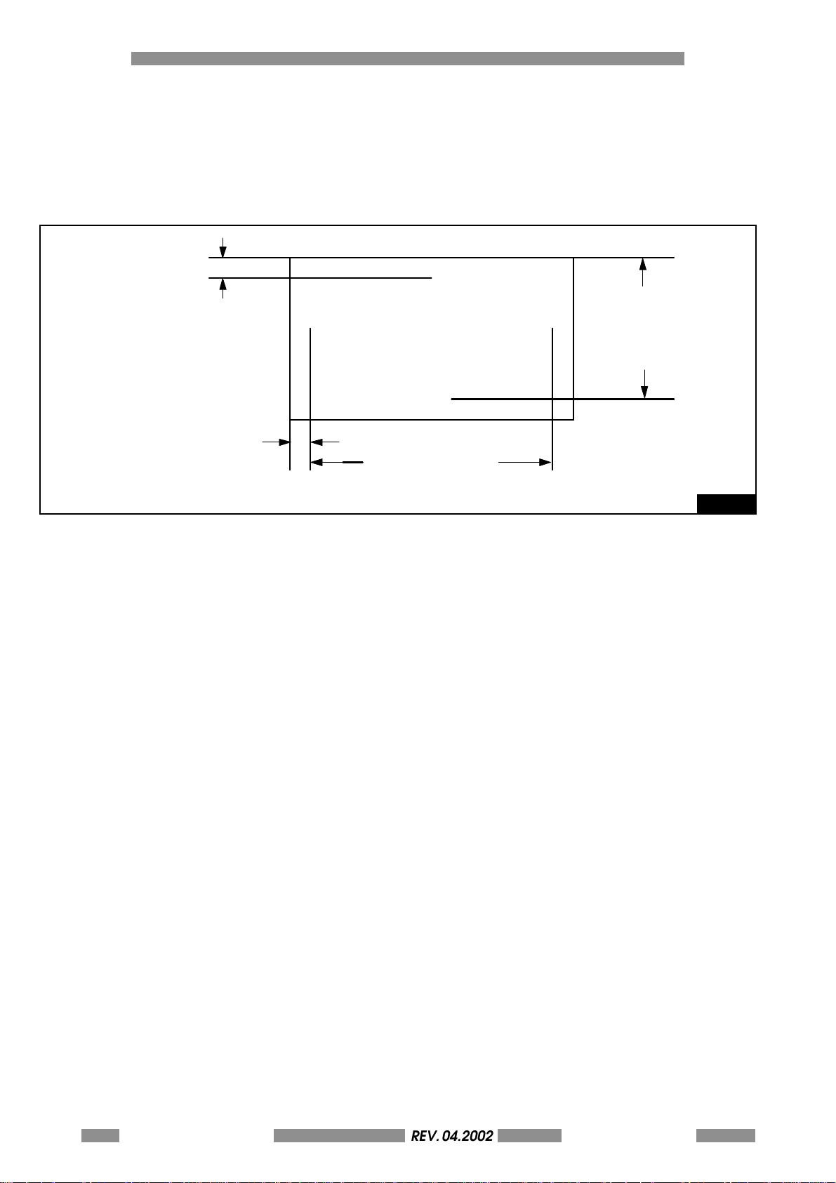
CLCD EDIT
REV. 05-2008
Card Stamping Area.
The card can be laid out in inches or metric
measurements. The operator can select the
measurements to be used.
The card Card Stamping Area and stamping
specifications are as follows:
Y = 7.0 M ( MIN )
0.28 “
X = 5.8M (MIN)
0.23 “
LEFT
TOP
BOTTOM
CR80 = 79M / 3.1 “
CR70 = 60M / 2.4 “
CR50 = 70M / 3.1 “
A The standard space between each standard
line is 0.16 inches (40 mm).
B The space to an OCR line (top and bottom) is
0.24 inches (6.0 mm).
C The standard character space is 0.10 inches
(2.5 mm)
The "Cost of 07" produces embossing of 10
characters per inch.
D The OCR character spacing is 0.142 inches
(3.6 mm)
The "Cost of 10" produces embossing of 7
characters per inch.
NOTE: The character spaceing is acheived by
the number of motor steps used to move the
card from one character to the adjacent
character.
Motor Steps are shown as "Cost".
The " Cost of 07 " produces a standard character
space. (10 cpi).
The " Cost of 10 " produces an OCR character
space. (7 cpi).
Each motor step (cost of 01) is transalated to
a distance of 0.36 mm ( 0.0142 ")
END
Y = 52M OR 2.04
CR80 / 70
X = 40M OR 1.56
CR50
Fig. C.1
C-84 METAL DOT MATRIXREV. 04.2002
OPERATORS MANUAL
Page 85
The following table can be used to determine the
REV. 05-2008
cost requirement of the specific character
spacing:
COST SPACING TABLE
LCD EDIT C
COST CHAR/INCH
05 14.40 5.56
06 11.70 4.61
07 10.00 3.96
08 8.80 3.47
09 7.82 3.08
10 7.04 2.87
11 6.40 2.52
12 5.87 2.31
13 5.42 2.14
14 5.03 1.98
DEFINITIONS:
X : Horizontal Axis - Left to Right on the Card.
Y : Vertical Axis - Top to Bottom on the Card.
Cost : Number of Motor Steps between character
(left to right)
OCR : Optical Character Recognition - Identical
to the large embossed numbers on a Credit
Card.
Field : A preset number of character spaces for
the operator to enter data, in a special
area of the card.
CHAR/DECIMETER
METAL DOT MATRIX
REV. 04.2002
OPERATORS MANUAL
C-85
Page 86
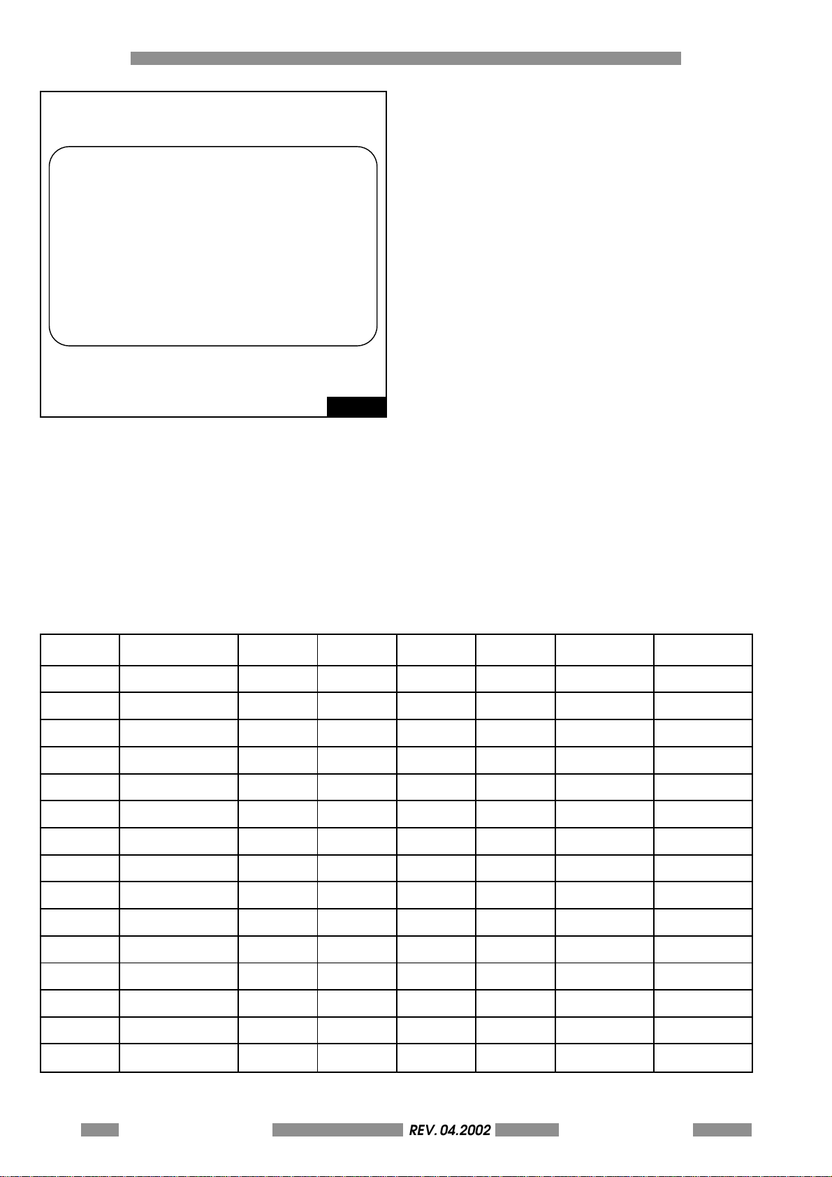
CLCD EDIT
REV. 05-2008
123456 - 6
MR. JOE SMITH
DOB-06/12/43
DR. HOWARD JACOBS
INSURANCE- CASH
U S HOSPITAL
DATE-01/12/95
EMMERGENCY
SEQUENCE
00002
SEX - MALE
00002
Card Layout (Preformatting)
It is recommended to make a layout of the card
to be formatted with all the special parameters,
such as mod checks, character size, number of
fields, field position, etc.. before starting the
formatting procedure.
What to do before programming a new format :
1 Layout a card as desired or use a similar
existing embossed card. There is a formatting
template at the back of this manual.
2 Make a table for the necessary programming
reqiurements.
There are blank forms at the back of this manual.
The following card format will be used as a
programming example in describing the
formatting functions in this section.
Example of a Formatted Card.
Fig. C.2
Format Layout
A specification sheet should be completed for
every format. The following is an example sheet
written in order to help in the preparation for the
formatting of the Card in Figure C.2. The template
at the end of this manual can be used in
determining the X and Y co-ordinates. The forms
at the end of this manual can be used to record
the necessary programming values.
FORMAT No.14 FORMAT NAME TEST
CARD FORMATTING SPECIFICATION SHEET
FLD # FIELD NAME X Y COST OCR # OF CHAR FIELD TYPE *
1 HOSP 100 057 07 N 12 P
2 ACCT # 023 082 10 Y 7 M-2
3 SEQ # 245 082 07 N 5 C00002
4 NAME 023 102 07 N 31 V
5 D.O.B ( P ) 023 118 07 N 31 P
6 D.O.B ( V ) 064 118 07 N 10 V
7 DATE 220 118 07 N 10 V
8 DOCTOR 023 154 07 N 31 V
9 TYPE 130 154 07 N 15 V
10 INS/SEX 023 174 07 N 31 V
11 INSURANCE 125 174 07 N 7 V
12 SEX 250 174 07 N 7 V
13 SEQUENCE 130 194 07 N 12 P
14 SEQ # 240 194 - - - F-03
15
* V = VARIABLE, M = MOD CHECK, C = COUNTER, P = PROTECTED, F = FIELD DUPLICATE
TIPPER N INFIL N
C-86 METAL DOT MATRIXREV. 04.2002
OPERATORS MANUAL
Page 87
PROTECTED DATA FIELDS
REV. 05-2008
FLD #
01 U S H O S P I T A L
05 D O B - D A T E -
10 I N S U R A N C E S E X
13 S E Q U E N C E
C.8 SETTING UP A FORMAT
LCD EDIT C
Fig. C.3
Note: W hi l e in t h e f o r ma t t in g m od e, p r e ss i n g t h e
F7
. key , will exit the LCD Edit Function.
Step-1: Switching On.
METAL DOT MATRIX V X.XX
READY
Step-2: Format Location Selection.
If the format is going to be the primary format,
(the format that is used most often), it should be
placed in location " 00 ". If it is not the primary
format, select any available format n u m b e r
between 01 and 19 inclusively.
A Host Computer can send data to these formats,
thus if the format to be designed will be used by
the Host, data processing must be notified to
determine the number to be given to the format.
Step-3: Format Selection
An example test format will be programmed in
format No. 14.
Refer to page 80 for the layout of the text.
Format 14 was selected because when the menu
was scanned by pressing ESC, F2 and then tabbing
through the fields, Format 14 had a default name
of "OPEN". All open formats will be named "OPEN".
METAL DOT MATRIX
REV. 04.2002
OPERATORS MANUAL
C-87
Page 88
CLCD EDIT
REV. 05-2008
An open format will have a default format in it.
FM:12 NAME: ABC FM: 13 NAME: WXY
FM:14 NAME: OPEN FM: 15 NAME: OPEN
Select Format 14 by pressing
ENTER
.
F4
14
,
S=SELECT E=EDIT D=DELETE
FORMAT NO:14 FORMAT NAME: OPEN SELECT:S
As shown in Figure, there is a new format in
location 14 named "OPEN". The aim is to program
a new format in this location. Thus an ' E ' must be
entered to change this
"OPEN" format.
Press E (For Editing / New Format).
S=SELECT E=EDIT D=DELETE
FORMAT NO:14 FORMAT NAME: OPEN SELECT:E
Step-4: Naming the new Format
The cursor is at the name location. Type in a new
name, in this case " TEST ".
S=SELECT E=EDIT D=DELETE
FORMAT NO:14 FORMAT NAME: TEST SELECT:E
,
Step-5: Requesting Format Options
The programmer can now define the various
options required in the format. All the special
options are defaulted to 'N' (NO), so to select
that option the operator must press 'Y' (YES).
Most of the special options pertain to the
individual fields within the format. Therefore they
will appear as each field is programmed. A
example format sheet has been completed to
demonstrate the procedure to be used for
programming. The test format will be
programmed as format 14
ENTER
Press
.
NO. OF DUPS: 00 - INC. CTRS WITH DUP: N
CHANGE COUNTER VALUE: N (Y/N)
Number of duplicate cards desired.
NO. OF DUPS: 000
The value entered in this location will program
the format to duplicate the message by the
number in this location.
000 = 1 original
002 = 1 original + 2 copies
999 = 1 original + 999 copies
C-88 METAL DOT MATRIXREV. 04.2002
OPERATORS MANUAL
Page 89
ENTER
REV. 05-2008
Press
.
NO. OF DUPS: 000 - INC. CTRS WITH DUP: N
CHANGE COUNTER VALUE: N (Y/N)
Increment counter when duplicating.
INC. CTRS WITH DUP: N
There is an option when cards are being
duplicated that allow the incremental counters
to advance for every card embossed or only
advance between sets of duplicated cards.
Exa mp le 1: Se nt tw o messa ges w ith
NO.OF DUPS: set to 001 and
INC.CTRS WITH DUP: set to N.
card 1 = count 001
---- First message
card 2 = count 001
LCD EDIT C
card 3 = count 002
---- Second message
card 4 = count 002
Exa mp le 2: Se nt tw o messa ges w ith
NO.OF DUPS: set to 001 and
INC.CTRS WITH DUP: set to Y.
card 1 = count 001
---- First message
card 2 = count 002
card 3 = count 003
---- Second message
card 4 = count 004
ENTER
Press
.
NO. OF DUPS: 000 - INC. CTRS WITH DUP: N
CHANGE COUNTER VALUE: N (Y/N)
METAL DOT MATRIX
REV. 04.2002
OPERATORS MANUAL
C-89
Page 90
CLCD EDIT
REV. 05-2008
Set Incremental Counters
CHANGE COUNTER VALUE: N (Y/N)
There are four counters which can be
programmed into each format. An 'N' will
advance the programming to screen LCD-14. All
counters remain as previously set. A 'Y' permits
changes to the counter values and other counter
parameters.
ENTER
Press
to go Step-6: Field Option Selection.
Press Y to program the incremental counters.
CT-1 (10 MAX) : 0
SEQ.STEP:1
INCR.: Y
Set Incremental Counter No: 1
CT-1 ( 10 MAX ) : 0
The number displayed will be the counter value
embossed on the next card.
Enter the new counter starting value which is
shown in field 3 of the specification sheet on
page 11 of this section.
Type in 00002 and press
ENT ER
.
CT-1 (10 MAX) : 00002
SEQ.STEP:1
INCR.: Y
Select the stepping value of the counter
SEQ.STEP: 1
The programmer can select the step value of the
sequential counter. The counter can be
programmed to step sequentially in increments
of 1 to 9.
Steps of 1 = 1-2-3-4-5-6-7-8-9
Steps of 2 = 2-4-6-8-10-12-14-16
Steps of 3 = 3-6-9-12-15-18-21-24
Steps of 4 = 4-8-12-16-20-24-28-32
Steps of 9 = 9-18-27-36-45-54-63-72-81
The step value of 1 will be used in the test
example.
CT-1 ( 10 MAX ) : 00002 JUST.: (R/L) R
MSD = 0 : Y SEQ.STEP: 1 INCR.: Y
C-90 METAL DOT MATRIXREV. 04.2002
OPERATORS MANUAL
Press
1
and
ENTER
.
Page 91
Counter Setting ( + / - )
ENTER
ENTER
REV. 05-2008
INCR.: Y
The counters can be set to count upward
(increment) or downward (decrement).
INCR.: Y INCR.: N
99 99
100 98
101 97
102 96
Incrementing will be selected for the test example.
LCD EDIT C
Press Y and
.
The LCD will now shift to the next counter to be
programmed. It is the same as LCD-9 except it will
display the next counter. Ii the last counter
programmed was counter 4 or if the tab key is
pressed the LCD display will shift to LCD-14.
Y/N MOD: N CTRS: N FLD DUP: N PROTECTED: N
FIELD NUMBER: 26
Step-6:Field Option Selection
The various options required to program the
format are shown in LCD-14. This example format
requires all the options shown above in line 1 of
LCD-14. Enter 'Y' in each of the locations. The 'Y'
will enable the programming of the selected
options in each field. Details for the variable
options are covered in this section.
Press 'Y' for Mod Check
Press 'Y' for CTRS
Press 'Y' for Field Dup
Press 'Y' for Protected Fields
Selecting the number of the fields to be
programmed
Field Number: 26
Enter the number of fields to be programmed into
the format. A maximum of 26 fields can be
entered.
Press
14
and
.
NAME: AA Y:028 X:023 COST OF : 07
NO OF CHAR:(MAX. 31) : 31 FONT (0-1) NORMAL
METAL DOT MATRIX
REV. 04.2002
OPERATORS MANUAL
C-91
Page 92
CLCD EDIT
REV. 05-2008
C.9 DESIGNING INDIVIDUAL FIELDS
LCD-15 will be displayed independently of any
'Y' selected options in the top line of
LCD-14 .
Step-1: Naming a Field
NAME: AA
Type in the name (HOSP) and Enter
Eight digits maximum and overwrite any existing
letters of the previous name that may be longer
than the new nam e.
Step-2: Entering the Y Coordinate of the
field.
Y: 028
The Y Coordinate is defined as the distance of the
bottom of the field to the top of the card. The
stamper can be set up for either inches or metric
measurements.
Examples: 1.5 inches = 150, 0.75 inches = 075, 0.3
inches = 030
Type in the three digit value and press
ENTER
.
Step-3: Entering the X Coordinate of the
field.
X: 023
The X coordinate is defined as the distance of the
left most character in the field from the left margin
of the card. The stamper can be set up for either
inches or metric meaurements.
Examples: 3 inches = 300, 2.25 inches = 225, 0.7
inches = 070
Type in the three digit value and press
ENTER
.
Step-4: Enter Character Spacing Required
COST: 07
Character spacing is defined on pages 9 and 10
of this manual. The normal standard spacing is
set at cost of 07 for 10 characters per inch. The
OCR spacing is set at cost of 10 for 7 characters
per inch.
C-92 METAL DOT MATRIXREV. 04.2002
OPERATORS MANUAL
Enter cost value and press
ENTER
.
Page 93
Step-5: Enter Maximum Field Length
REV. 05-2008
No. OF CHAR : 31
The programmer can limit the number of
characters that will be accepted by the stamper.
The maximum limit is determined by the value
displayed at the end of the second line of the
LCD.
LCD EDIT C
Type in the desired value and press
ENTER
.
Step-6: Font Type
There are two selectable types of font. The selection
of the type of font is determined by the stamping
wheel configuration. The selections possible for
any stamper are given during the initial installation.
CODE FONT TYPE
0 Normal (Standard Characters )
1 OCR Characters
Enter font type and press
ENTER
.
The following options are now available.
A Branch to the programming of the next field if
this was not the last field to be programmed
and none of the field options in LCD-14 were
selected.
B Branch to options for fields if one or more of
the fields options in LCD-14 were selected.
C Branch to storing format, if this was the last
field.
In the case of the example text card above, the
branch would go to options for fields.
Options for Fields
NAME: DOCTOR TYPE: ( V-M-P-C-F ) VARIABLE
V = Variable Data, M = Mod Check Field, P =
Protected Data,
C = Sequential Counter Field, F = Field Duplicated.
LCD-16 will be displayed if:
A One or more of the Field Options were selected.
B The design data for this field has been
completed.
METAL DOT MATRIX
REV. 04.2002
OPERATORS MANUAL
C-93
Page 94
CLCD EDIT
REV. 05-2008
Step-1: Selecting The Variable Data Field.
Selecting this field as a variable will permit the
operator to enter data to this field when stamping
with the LCD Edit or on line when in a stored
format protcol.
ENTER
Press V or
.
The following options are now available.
A Branch to options for fields if one or more of
the fields options in LCD-14 were selected.
B Branch to storing format, if this was the last
field.
Step-2: Mod Check Field.
A Mod Check Field is a numeric check field in
which the numeric data must satisfy a specfiic
algorithm. This procedure is used to reduce the
chance of wrong entry of numbers in a seies of
numbers that must be correct (Account #, Patient
#, etc.. ). For the algorithm and the series of
numbers satisfying the algorithms refers to the
manual of platic embosser machines
Press M.
NAME: ACCT # TYPE: (V-M-P-C-F) MOD CK
AUTO MOD (Y/N) N REDUNDANCY: N TYPE: 0
Selection of the Auto Mod Check (innactive at
this time)
AUTO MOD-CK (Y/N): N
A 'Y' will enable the on-line Mod Check. This will
allow the on-line transmission of a number
withoutn a check digit and the stamper will
calculate the check digit and enter it to the end
of the transmitted set of numbers.
A 'N' will not enable the on-line Mod Check.
C-94 METAL DOT MATRIXREV. 04.2002
OPERATORS MANUAL
Page 95
Selection of Mod Check Type
REV. 05-2008
TYPE: 00
0 = MOD 11 Non Consecutive Algorithm
1 = MOD 11 Consecutive Algorithm
2 = MOD 10 LUHN Algorithm
Details on the types of algorithms are given in the
Manual METAL DOT MATRIX.
Press Mod Type and Return.
The following options are now available.
A Branch to options for fields if one or more of
the fields options in LCD-14 were selected
B Branch to storing format, if this was the last
field.
Step-3: Protected Fields.
A Protected field is a field where the data is
entered into the format during the programming
or the editing of the format. The operator will not
need to enter this data during data entry. Data
such as Department Name, field headings such
as DOB, SEX can be entered as protected data.
LCD EDIT C
Press P
NAME: HOSP TYPE: ( V-M-P-C-F ) PROTECTED
DATA: U S HOSPITAL
Type in the desired protected data following
Data: in LCD-18
ENTER
Press
The following options are now available.
A Branch to options for fields if one or more of
the fields options in LCD-14 were selected
B Branch to storing format, if this was the last
field.
Step-4: Counters.
The counters selected in the section on the setting
up of the formats can now be entered into the
fields designated for the counters.
Press C
NAME: SEQ TYPE: ( V-M-P-C-F ) COUNTERS
COUNTER NO: 1
METAL DOT MATRIX
REV. 04.2002
OPERATORS MANUAL
C-95
Page 96
CLCD EDIT
REV. 05-2008
Enter the counter number that was programmed
for this field when the format was set up.
Press counternumber and Enter
The following options are now available.
A Branch to options for fields if one or more of
the fields options in LCD-14 were selected.
B Branch to storing format, if this was the last
field.
Step-5: Field Duplication.
The field duplication allows the transfer of data
from one field to another automatically. The
programmer must identify the field to be
duplicated. In fields that have an incremental
counter, the programmer has the option of
duplicating the number or having the number in
the duplicated field incremented or decremented.
This fuction is used when the field being
programmed is exactly the same as one of the
previous fields in all characteristics except for the
X and y coordinates and the sequential counter
value.
Press F
NAME: SEQ TYPE: ( V-M-P-C-F ) FIELD DUP
FIELD DUPED: 01 Y:028 X:023 CTRS ADV: N
Enter the field to be duplicated
FIELD DUPED: 03
Enter the number of the field to be duplicated.
The TEST example has field #14 a dup of field #3.
In the example case enter 03 and press Enter.
Select the sequential counter operation
CTRS ADV: N
An Y forces the updating of the duped counter
An N dosen't foice any update of the duped
counter
The following options are now available.
A Branch to options for fields if one or more of
the fields options in LCD-14 were selected.
B Branch to storing format, if this was the last
field.
C-96 METAL DOT MATRIXREV. 04.2002
OPERATORS MANUAL
Page 97

C.10 STORING THE FORMAT
REV. 05-2008
THE LAST FIELD IS COMPLETED-PRESS F10 TO SAVE
THE FORMAT OR SHIFT TAB TO COME BACK
LCD EDIT C
Press
F10
The format will be stored.
METAL DOT MATRIX
REV. 04.2002
OPERATORS MANUAL
C-97
Page 98

CLCD EDIT
REV. 05-2008
This page is left empty
due to editing reason
C-98 METAL DOT MATRIXREV. 04.2002
OPERATORS MANUAL
Page 99

Page 100

INDICE ALFANUMERICO
MF Group S.p.A. - CIM division
Via O. Serra, 2
40012 Calderara di Reno Bologna - ITALY
Tel. +39 051 64.65.011
Fax + 39 051 64.65.012
E-mail: [email protected] www.cimitaly.it
ACIM SDN. BHD. - Asia Pacific
Suite 13-5, 13th Floor
Wisma UOA II, Jalan Pinang
Timbro rivenditore Sales Mark
50450 Kuala Lumpur - MALAYSIA
Tel. + 60 3.2166.4166
Fax. + 60 3.2166.4163
[email protected]
CIM USA Inc. - Americas
10813 N.W. 30th Street - Suite 108
Miami, FL 33172 - USA
Tel. + 1 305.639.30.40
Fax. + 1 305.639.30.60
E-mail: [email protected] - www.cim-usa.com
I-270 T 1000 PROREV. 04.2001
 Loading...