

Page 1
Page 2

Page 3

FOREWORD
This manual contains installation and operation information for the CIM K500 Optima
Series card printe rs manufactured by CIM.
RETURN MATERIALS AUTHORIZATION
Before returning a ny equipment to CIM S.p.A. for in-warranty or out-of-warranty repair,
contact Repair Administration for a Return Materials Authorization (RMA) number.
Repack the equipment in the original pa cking material and mark the RMA number
clearly on the outside. Ship the equipment, freight prepaid, to the address listed below:
COPYRIGHT NOTICE
This document contains information proprietary to CIM S.p.A.
This document and the information contained within are Copyrighted by CIM
S.p.A. and may not be duplicated in full or in pa rt by any person without
written approval from CIM. While every e ffort has been made to keep the information
contained within current and accurate as of the date of publication, no guarantee is
given that the document is error-free or that it is accurate with regard toany specification.
CIM reserves the right to ma ke changes, for the purpose of product improvement,
at any time.
TRADEMARKS
K 500 Optima is a service mark and CIM is a registered trademark of CIM S.p.A.
Windows and MS.DOS are registered trademarks of Microso ft Corp. All other trademarks
or registered trademarks are marks of their respect ive holders.
iii
iii
Page 4
WITH THE CIMAGE CARD A WORLD OF SERVICES ARE NOW A V AILABLE TO YOU
Dear Customer, Thank you for buying a CIM product. The quality of CIM products is guaranteed over
time and backed by quality service. CIM provides through the CIMAGE CARD an after-sales service
wich you can make use of by providing us the code number printed on the back side of the card. This
will enable to you contact uor technical Service for a period of 12 months.
WHA T DOES THE CIMAGE CARD OFFER
1 YEAR OF TECHNICAL SUPPOR T FREE OF CHARGE HELP DESK SUPPOR T
T el +39 051 6465 096 - fax +39 051 6465 012
e-mail: dolphinsupport@cimitaly .it - www.cimital y .it
On demand assistance with all problems relating to hardware, software, installation or outright
malfunctioning of the printer product. The technical support is offered free of charge within the
appliacable 24 month warranty period of the product and thereafter extended on request and on
contractual basis.
PRODUCT WARRANTY
Repair or upgrades of defective printers is carried out by CIM certified technicians. In-house service
and repair is offered free of charge (all shipping and handling charges to be paid by customer) within
the applicable 12 months warranty period on the product. In -house service and repair is also available
for products beyond the standard warranty period. In such case the current rate for in-house service
and repair will be applied.
CIM TECHNICAL SUPPORT
Page 5

v
INTRODUCTION
Thank you for choosing the CIM K 500 Optima Plastic Card Printer.
CIM’s P series card printers offer a low cost, high quality solution to those requiring
computer-controlled printing and encoding of credit card style plastic cards, Card
applications include personalized identification, access control, visitor, membership,
badges and tags.
This manual guides you to efficient start up and operation of your new Card Printer.
K 500 Optima PRINTER MODELS
The CIM Product Number tells a story:
Here is a quick review of the CIM Card Printer Series numbering and lettering
system to help you.
The K 500 Optima Plastic Card Printer employs Dye Sublimation and Resin Thermal
Transfer technologies. Model numbers include identifiers that specify options are shown
using the following lettering conventions:
K500 Optima - X X X X X - X X X
Smart Card: Software:
O = No O = WindCard Cd only
E = Yes F = Windows driver only
Magnetic Encoder: B = WindCard & drivers
O = No Language:
M = Yes O = No manual
Magnetic Encoder Options: A = English & Spanish
O = No B = French & German
1 = Stripe down HICO I = Italian
2 = Stripe Down LOCO P = Brazilian Portugese
3 = Stripe Up HICO C = Chinese
4 = Stripe Up LOCO J = Japanese
Memory: Power Cord:
O = Standard O = None
Interface: A = 120 VAC
P = Parallel (Centronics 36 pins) E = 220 VAC
U = UK
}
Ship-away kit
Page 6

vi
ICONS
Throughout this manual, different icons highlight important information, as follows:
Important general information.
Mechanical hazard, such as one associated with moving parts,
capable of resulting in equipment damage or personal injury.
Electrical hazard, such as an exposed voltage point, capable of
causing electrical shock and personal injury.
An area where electrostatic discharge (ESD) can cause
component damage. Use a grounding wrist band.
Elevated temperature hazard, capable of producing a burn.
Keep Card Printer clean by minimizing cover open time.
Page 7

vii
1
2
3
4
5
6
TABLE OF CONTENTS
GETTING STARTED • • • • • • • • • 1
1•1 Unpacking your • • • • • • • • • • • • • • • • • • • • • • • • • • 1
1•2 Indicators and control • • • • • • • • • • • • • • • • • • • • • • 3
1•3 Printer installation • • • • • • • • • • • • • • • • • • • • • • • • 4
OPERATION • • • • • • • • • • • • • 5
2•1 Printer Features • • • • • • • • • • • • • • • • • • • • • • • • • • 5
2•2 Loading Printing Ribbons • • • • • • • • • • • • • • • • • • • 6
2•3 Loading Lamination Patch • • • • • • • • • • • • • • • • • • • 8
2•4 Loading cards • • • • • • • • • • • • • • • • • • • • • • • • • • • 9
A- Card Feeder • • • • • • • • • • • • • • • • • • • • • • • • • • • 9
B- Card Cleaning Cartridge • • • • • • • • • • • • • • • • • • 10
C- Card Thickness Control Lever • • • • • • • • • • • • • • • 11
D- Card Output Hopper • • • • • • • • • • • • • • • • • • • • • 11
2•5 Reject Card Box • • • • • • • • • • • • • • • • • • • • • • • • • • 12
2•6 Feeding one card at a time • • • • • • • • • • • • • • • • • • 14
2•7 Printing a test card • • • • • • • • • • • • • • • • • • • • • • • • 15
2•8 Printer menu information • • • • • • • • • • • • • • • • • • • 16
PRINTING A SAMPLE CARD • • • • • • 21
3•1 Install Driver on windows 95/98 • • • • • • • • • • • • • • • 22
3•2 Install Driver on windows 200 0 & NT4.0 • • • • • • • • • 23
3•3 Set Printer Driver Option • • • • • • • • • • • • • • • • • • • • 23
3•4 printing a sample card • • • • • • • • • • • • • • • • • • • • • 24
CLEANING • • • • • • • • • • • • • • 25
4•1 Cleaning system • • • • • • • • • • • • • • • • • • • • • • • • • • 26
4•2 Cleaning the print head • • • • • • • • • • • • • • • • • • • • • 27
4•3 Cleaning the Laminator rollers • • • • • • • • • • • • • • • • 28
4•4 Card Cleaning cartridge • • • • • • • • • • • • • • • • • • • • 29
TROUBLESHOOTING • • • • • • • • • 31
5•1 Interpreting LCD Display messages • • • • • • • • • • • • 31
A- About the Printing Station • • • • • • • • • • • • • • • • • 31
B- About the Laminator Station • • • • • • • • • • • • • • • 34
5•2 Print Quality Issues • • • • • • • • • • • • • • • • • • • • • • • • 35
TECHNICAL SPECIFICATIONS • • • • • 39
Page 8

viii
APPENDIX A • • • • • • • • • • • • • 43
Introduction • • • • • • • • • • • • • • • • • • • • • • • • • • • • • • • 43
A- Media Loading orientation • • • • • • • • • • • • • • • • 44
B- Magnetic Encoder Cleaning • • • • • • • • • • • • • • • • 45
APPENDIX B • • • • • • • • • • • • • 46
Introduction • • • • • • • • • • • • • • • • • • • • • • • • • • • • • • • 46
A- Media Loading orientation • • • • • • • • • • • • • • • • 47
B- Smart Card Contact Station Interface • • • • • • • • • 47
Page 9

1
GETTING STARTED
1
GETTING STARTED
1 • 1 Unpacking your card printer
Your K 500 Optima printer ships in a carton and protective anti-static bag. Keep all
packaging material in case you need to move or re-ship the printer.
While unpacking, inspect the carton to ensure that no damage occured during
shipping.
Please ensure that you have a clean and nearly dust free environment for proper
operation and storage of the printer.
Page 10
2
GETTING STARTED
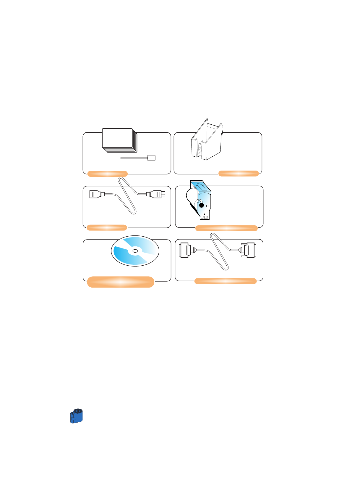
In addition to user documentation, make sure the following items are included with
your K 500 Optima printer:
If any items are missing, please contact your dealer.
CLEANING KIT
POWER CABLE
PRINTER DRIVER DISK
(floppy or/and CD)
CARD HOPPER
CLEANING CARTRIDGE
CENTRONICS CABLE
Page 11
Page 12
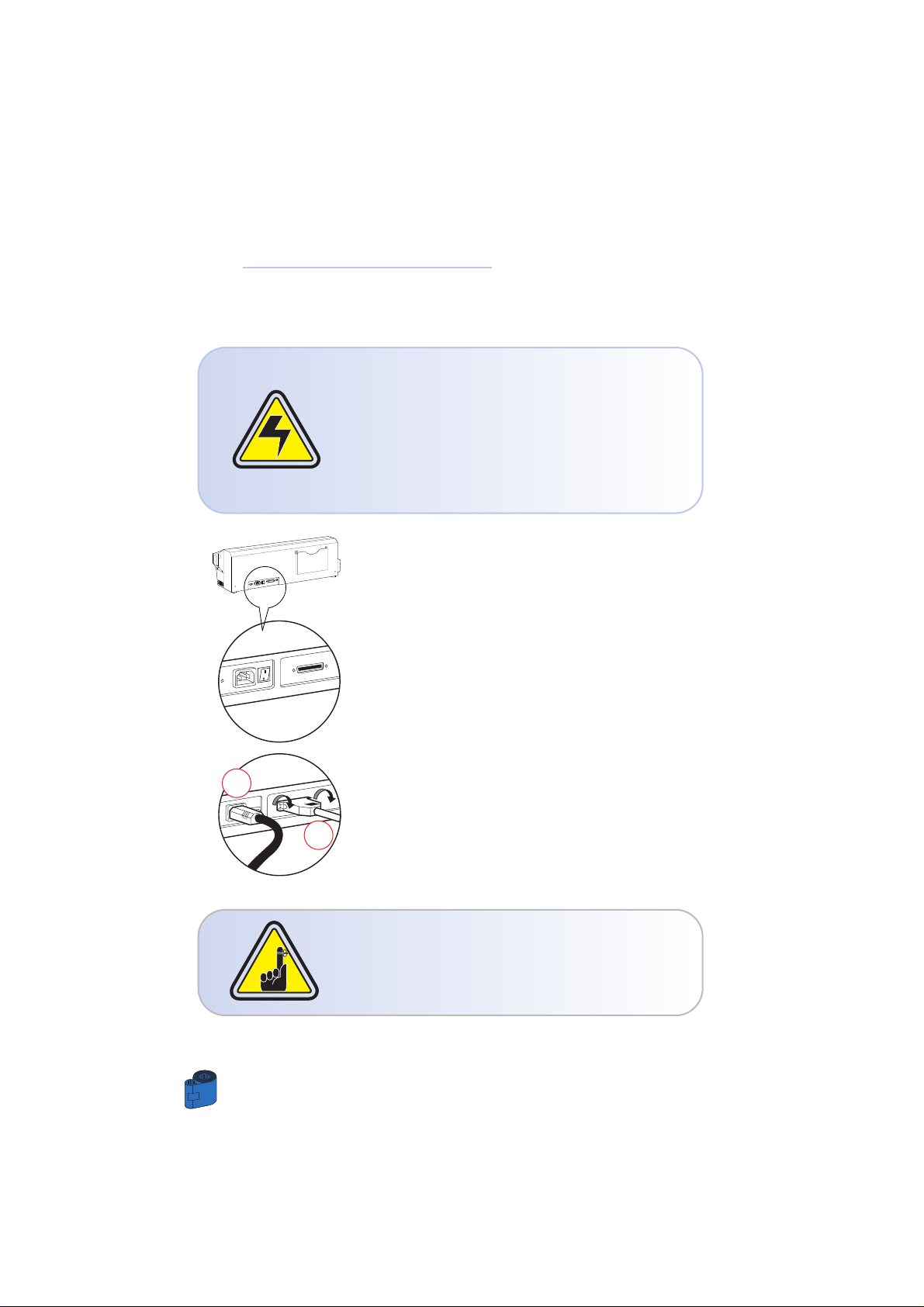
1 • 3 Printer Installation
The following will guide you through the installation of your K 500 Optima printer.
CAUTION: Limit AC power supplied to the K 500
Optima Printer to 110 - 230 V AC, 60 - 50 Hz for an
associated 1,40A - 0,80A. Limit excess current draw
to 16 amps or less, using an associated circuit breaker
or other such device. Never operate the printer in
a location where operator, computer, or printer can
get wet. Personal injury could result. The
printer must be connected to an earthed electrical
power supply and properly protected against
electrical surges and grounding faults.
1 • Place the printer in a location that allows easy
access to all sides. The printer should never be
operated while resting on its side or upside down.
2 • Place the printer’s power switch in the OFF (O)
position.
3 • Insert the power cable to the printer power
socket and attach to grounded electrical socket of
the proper voltage and type.
4 • Attach interface cable to printer and computer
and then secure.
5 • Switch power on.
CAUTION: Intermittent or unpredictable operation
may occur from unsecured connectors. If
damaged, the power cable must be replaced by an
exact equivalent.
Use only Parallel Cable under 3 Meters in length.
3
4
GETTING STARTED
4
Page 13
5
OPERATION
2
OPERATION
2 • 1 Printer Features
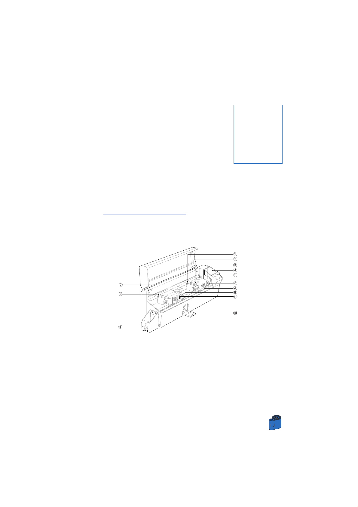
The following shows the features found on your K 500 Optima Printer:
Standard Features: Optional Features:
1 • Print Head Unlock Lever A • Smart Card Contact Station
2 • Print Head B • Magnetic Encoder Station
3 • Card Thickness Control Lever
4 • Card Feeder
5 • LCD Display and two panel Buttons
6 • Card Cleaning Cartridge
7 • Laminator
8 • Laminator Unlock Lever
9 • Card Output Hopper
10 • Rejected Card Box
11 • Cleaning Roller
Page 14
OPERATION
6
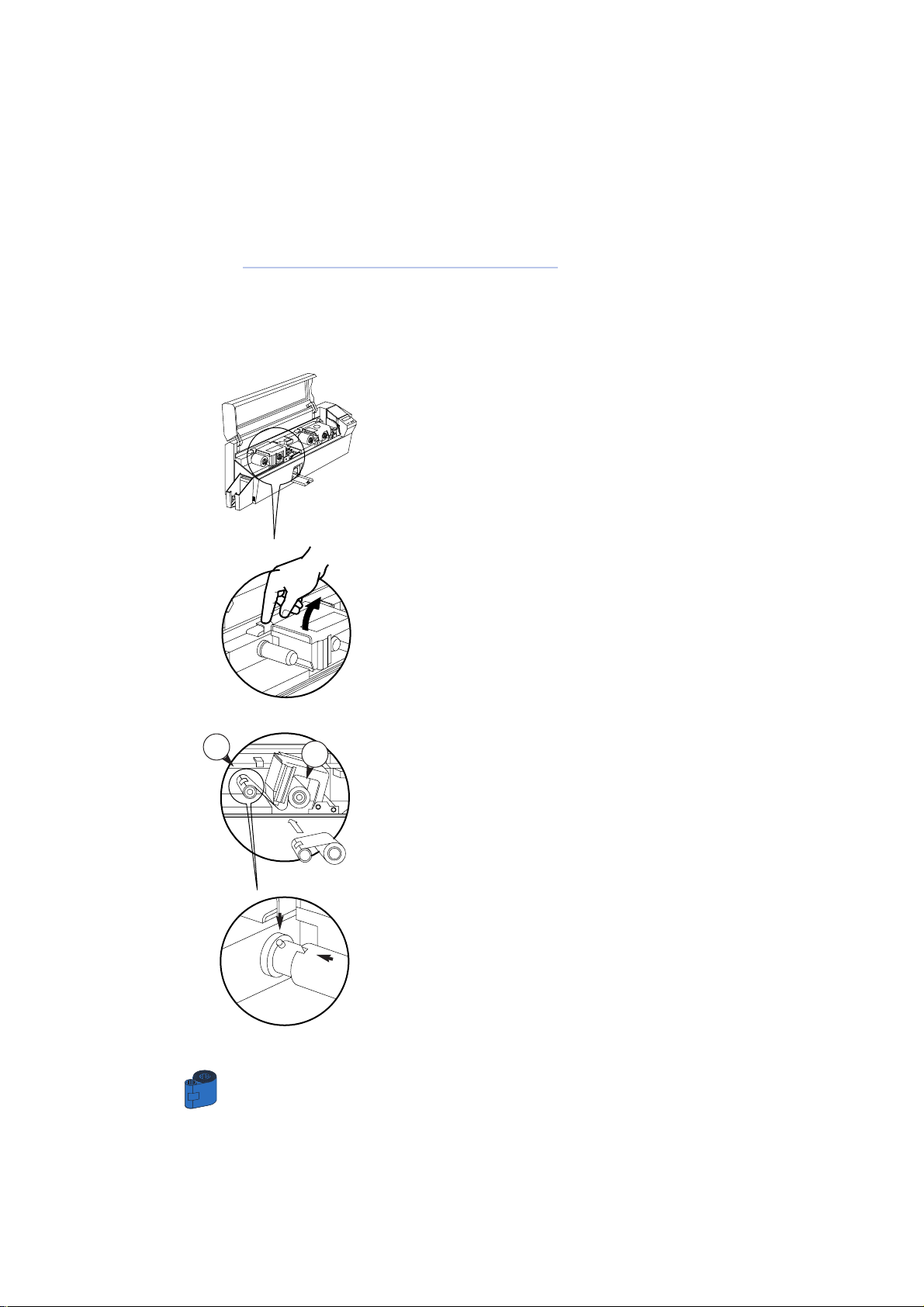
2 • 2 Loading Printing Ribbons
The K 500 Optima Printer requires approved ribbons. The Resin Thermal Transfer
and Dye Sublimation ribbons and Lamination are specifically designedfor your K 500
Optima Printer. For optimum performance and printer life (Print Head), always use
approved ribbons.
DO NOT TOUCH the print head or the electronic
components on the print head carriage.
Discharges ofelectrostatic charge from the human
body or other surfaces can damage the print head
or other electronic components used in this device.
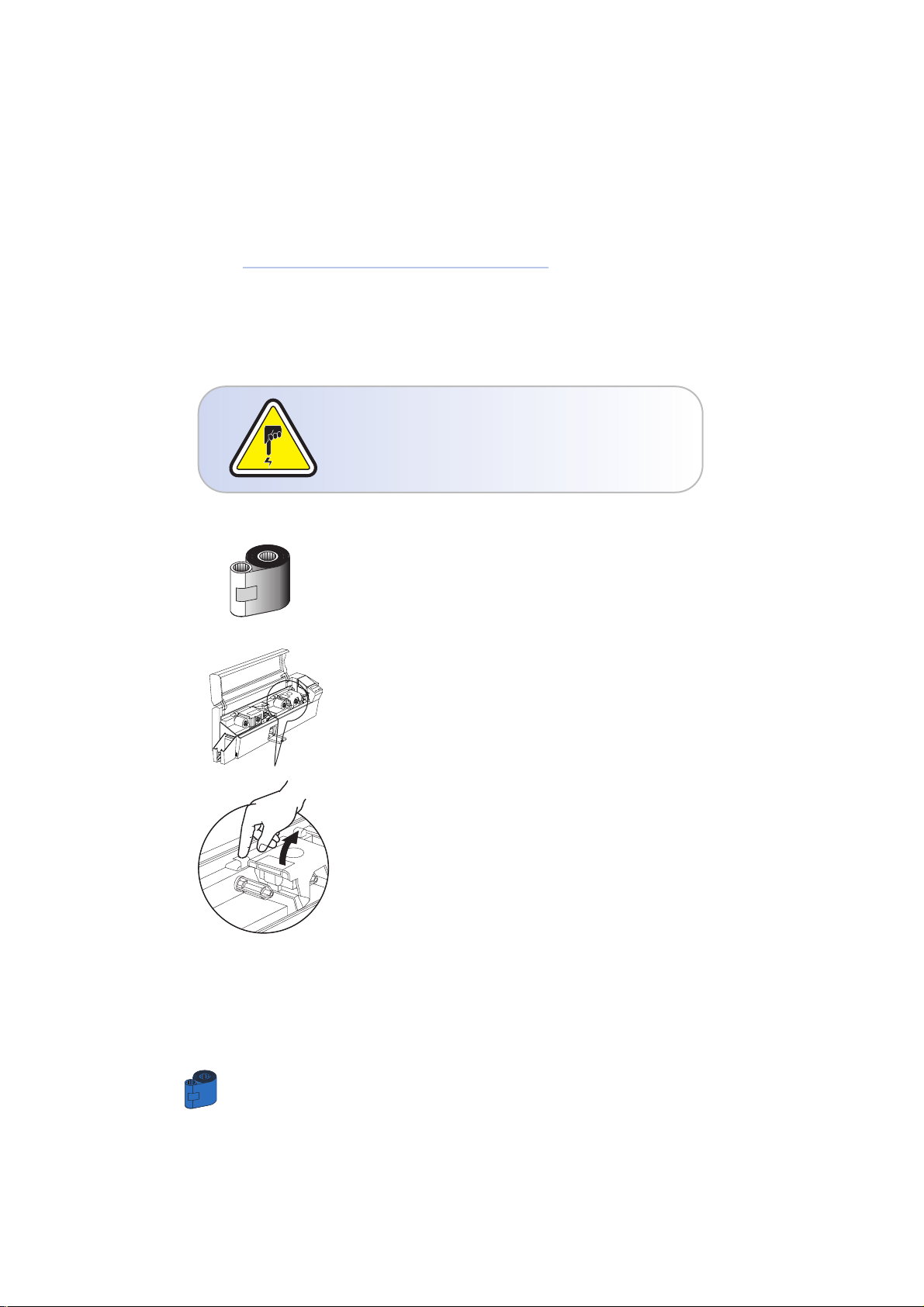
1 • Remove ribbon from packaging.
2 • With printer power ON and Printer Ready status,
open cover and press down on the Print Head
Unlock Lever to open the print head carriage. The
print head carriage will pop open.
Page 15
OPERATION
7
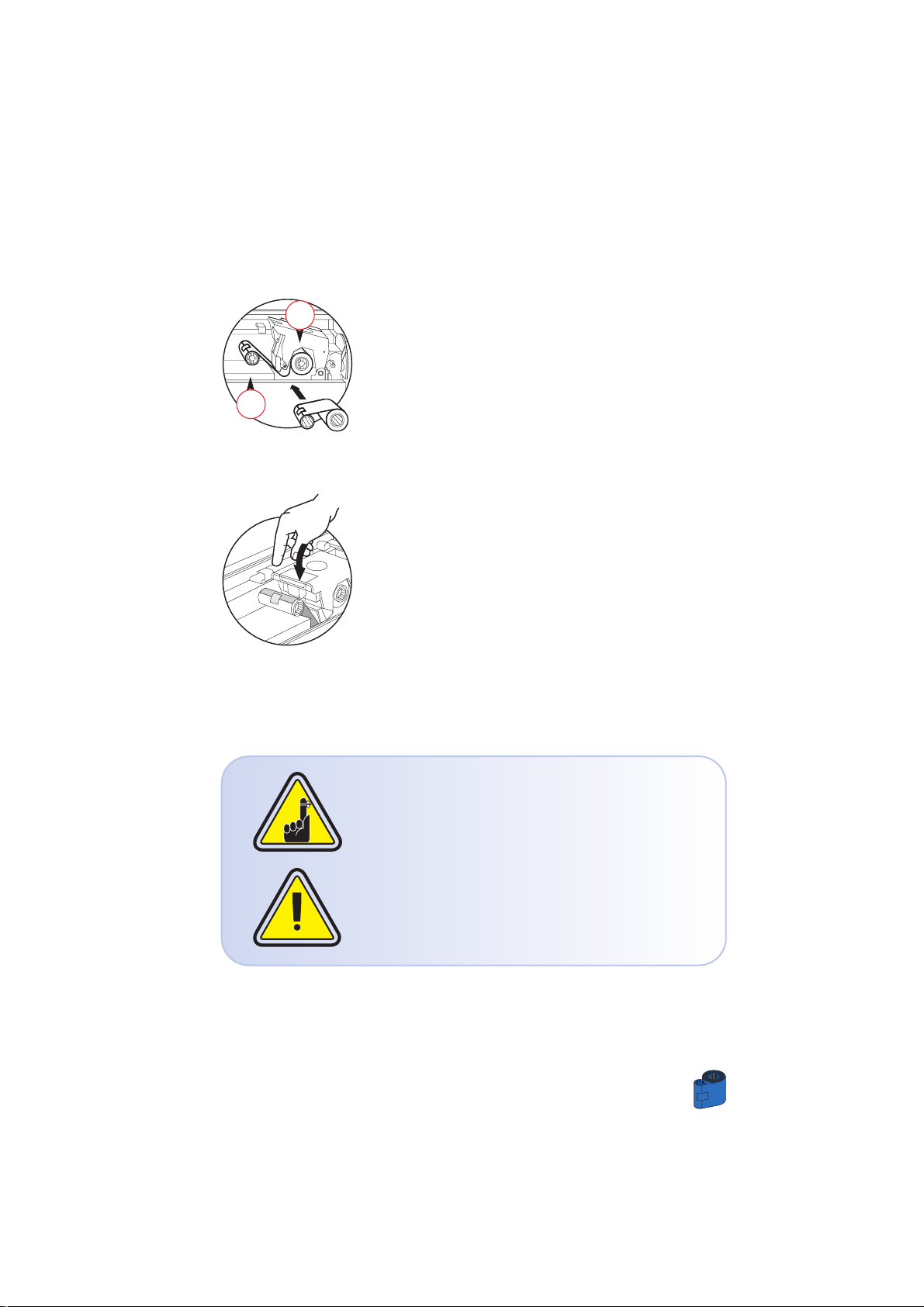
3 • Load ribbon onto the supply spindle “1”
(under print head carriage) and empty core (with
tape attached) onto the take-up spindle “2”. Make
sure the ribbon comes off the top of the supply
spindle and feeds to the top of the take-up spindle.
4 • Push down on the Print Head Lock Lever until an
audible “click” signals the locked-down position.
5 • Close Cover
Please note that the ribbon automatically
synchronises whenever the print head lock down
occurs.
The card flipper will not operate and an error will
be indicated if you try to flip a card when the cover
is open.
2
1
Page 16
OPERATION
8
2 • 3 Loading Lamination Patch
The K 500 Optima Printer requires approved patches.
Clear patches, hologram patches or Overlay varnishes are specifically designed for
your K 500 Optima Printer. For optimum performance and printer life (Laminator),
always use approved patches.
1 • Remove patch from packaging.
2 • With printer power ON and printer Ready status,
open cover.
3 • Press down on the Laminator Unlock Lever to
open the laminator bracket. The laminator bracket
will pop open.
4 • Load patch onto the supply spindle “1”
(under laminator bracket) and align the notch of the
empty core with the spindle screw (with tape
attached) onto the take-up spindle “2” .
Make sure the patch comes off the top of the supply
spindle and feeds to the top of the take-up spindle.
5 • Push down on the Laminator Lock Lever until an
audible “click” signals the locked-down position.
6 • Close Cover
.Please note that the ribbon automatically
synchronises whenever the laminator head
lock down occurs.
2
1
Page 17
OPERATION
9
2 • 4 Loading Cards
To help you load, print, and collect cards, the K 500 Optima has the following items:
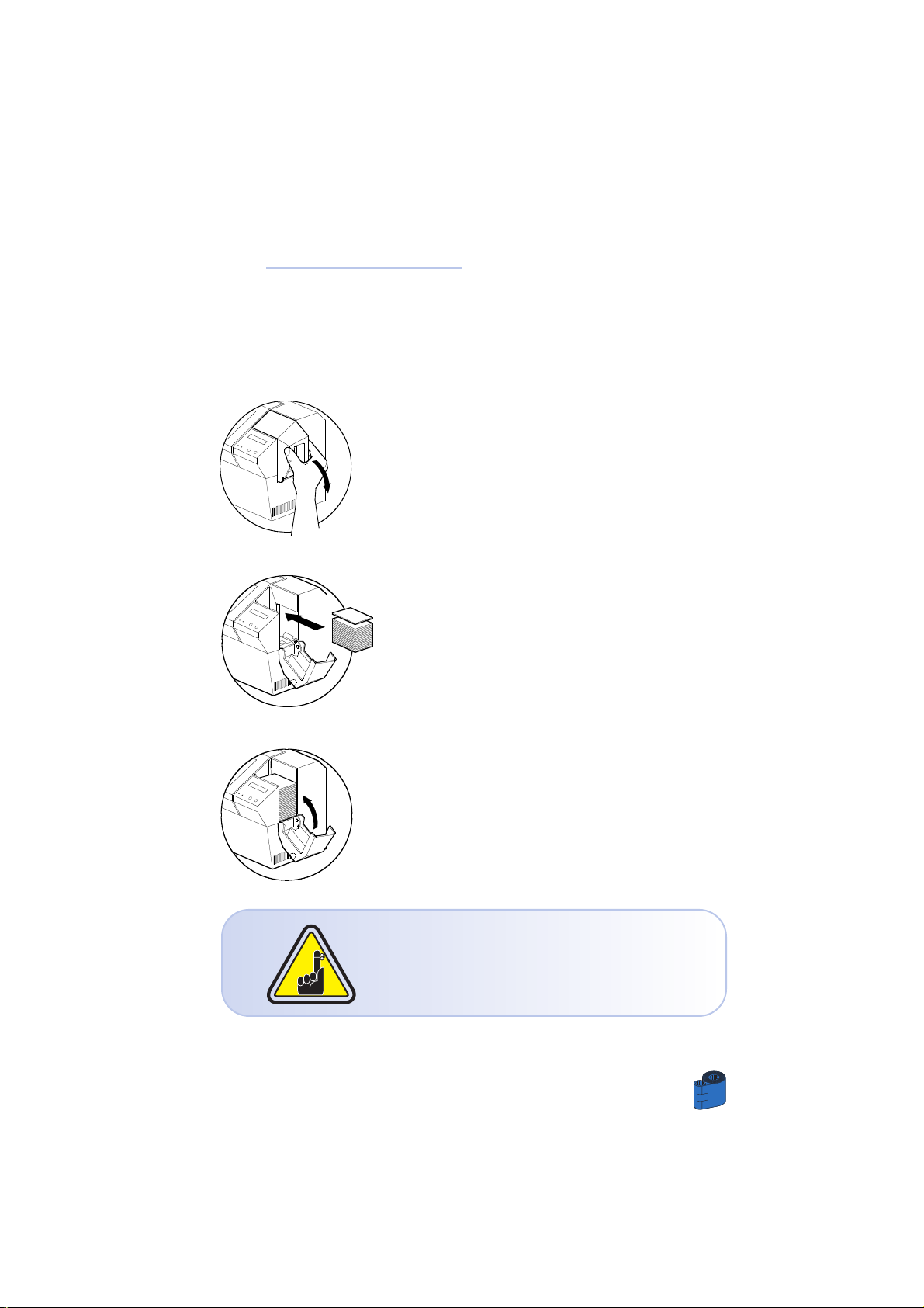
A - CARD FEEDER
This items is used for loading cards.
1 • Open Card Feeder Cover by putting your fingers
on both sides and rotating the cover in a clockwise
direction to the open position.
2 • Install cards into Feeder* as shown.
3 • Close Card Feeder Cover.
DO NOT bend cards or touch print surfaces as this
can reduce print quality. The surface of the cards
must remain clean and dust free. Always store
cards in an enclosed container. Ideally, use cards
as soon as possible. If cards stick together,
carefully shuffle them.
* See Chapter 6, Technical Specifications, for card requirements and capacities.
Page 18
10
OPERATION
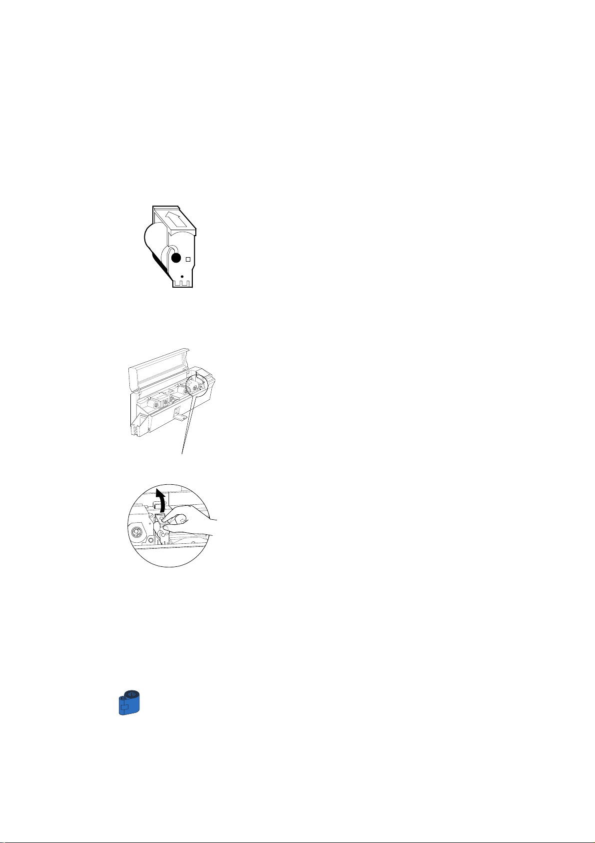
B - INSTALL CARD CLEANING CARTRIDGE
This items is used to clean the cards entering the printer.
It must installed before using the printer.
1 • Remove Card Cleaning Cartridge from
plastic bag and peel off protective wrapper from
adhesive cleaning roller.
2 • Open printer cover and remove the yellow
reminder tape from the location for the Cleaning
Cartridge.
3 • Make sure the arrow on top of the assembly is
facing towards the rear of the printer.
Hook assembly into slot on printer and rotate down.
Ensure the assembly locks in place.
Page 19
11
OPERATION
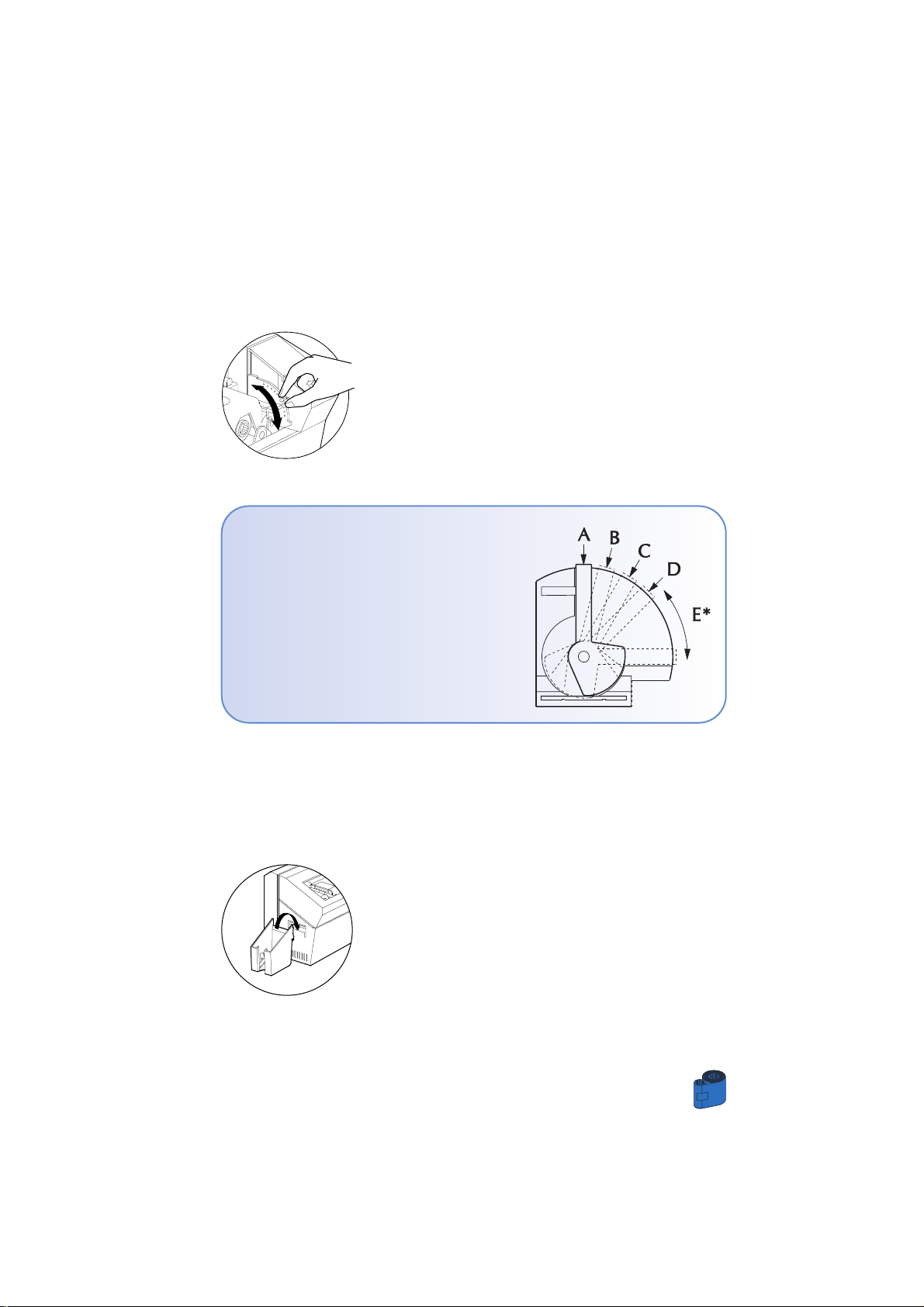
C - CARD THICKNESS CONTROL LEVER
This items is operated by the user to prevent more than one card feeding into the
printer at the same time and causing a jam.
Open cover, and adjust lever to the correct
position for the card thickness you are using. Repeat
for different card thickness. (Factory setting is for 30
mil (0,762 mm) card thickness). See diagram below:
Card thickness:
A - 60mil (1.524mm) to 50mil (1.27mm)
B - 40mil (1.016mm)
C - 30mil (0.762mm)
D - 20mil (0.508mm)
E* - Less than 20mil (0.508mm)
*Start at lowest position and move lever up
to match card thickness.
For other card thickness, start lever at lowest
position and move up until cards feed.
Note: For Lamination cards should only be 30 mil cards, and composite PVC is prefered
D - CARD OUTPUT HOPPER
This items is used for printing cards.
Install card Output hopper onto printer by hooking
over bottom edge of card exit aperture.
Page 20

12
OPERATION
2 • 5 Rejected Card Box
The K 500 Optima Printer is equipped with a Rejected card Box. When an encoding cannot
be completed, the card is ejected into the Rejected Card Box. The K 500 Optima Printer
counts the number of cards which go into the Reject Card Box. After 20 cards the printer
stops, the Amber LED Flashes and a LCD Message is displayed indicating the need to empty
the reject box.
WHEN TO MAINTAIN
When the LCD screen reports message
HOW TO MAINTAIN
1 • Press the top of the Rejected Card Box Door as
shown. Allow the door to swing down and open.
2 • Remove all cards from the Rejected Card Box.
REJECT BOX FULL
Page 21

OPERATION
13
3 • Swing the Rejected Card Box Door and press the
top. An audible “click” signals the locked position.
4 • Press the Clear Button on the front panel to
re-start the current printer job and to clear the
rejected cards counter.
Page 22

14
OPERATION
2 • 6 Feeding one card at a time
A Manual Feed Slot is avalable on the side of the Card Feeder cover for feeding single
cards. Cleaning Cards are fed manually through this slot.
The Feeder must be empty
for manual card feeding to work properly.
For one-at-a-time printing, feed cards through slot
on side of Feeder.
Do not feed more than one card at a time.
Page 23
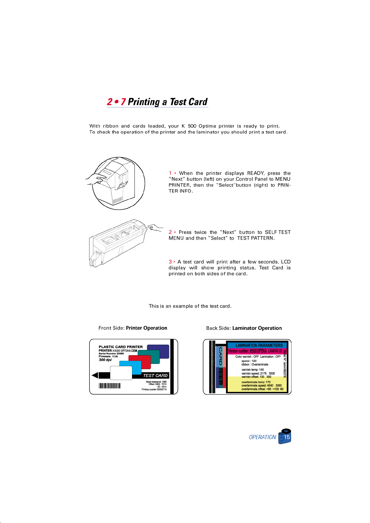
Page 24

16
OPERATION
2 • 8 Printer Menu Information
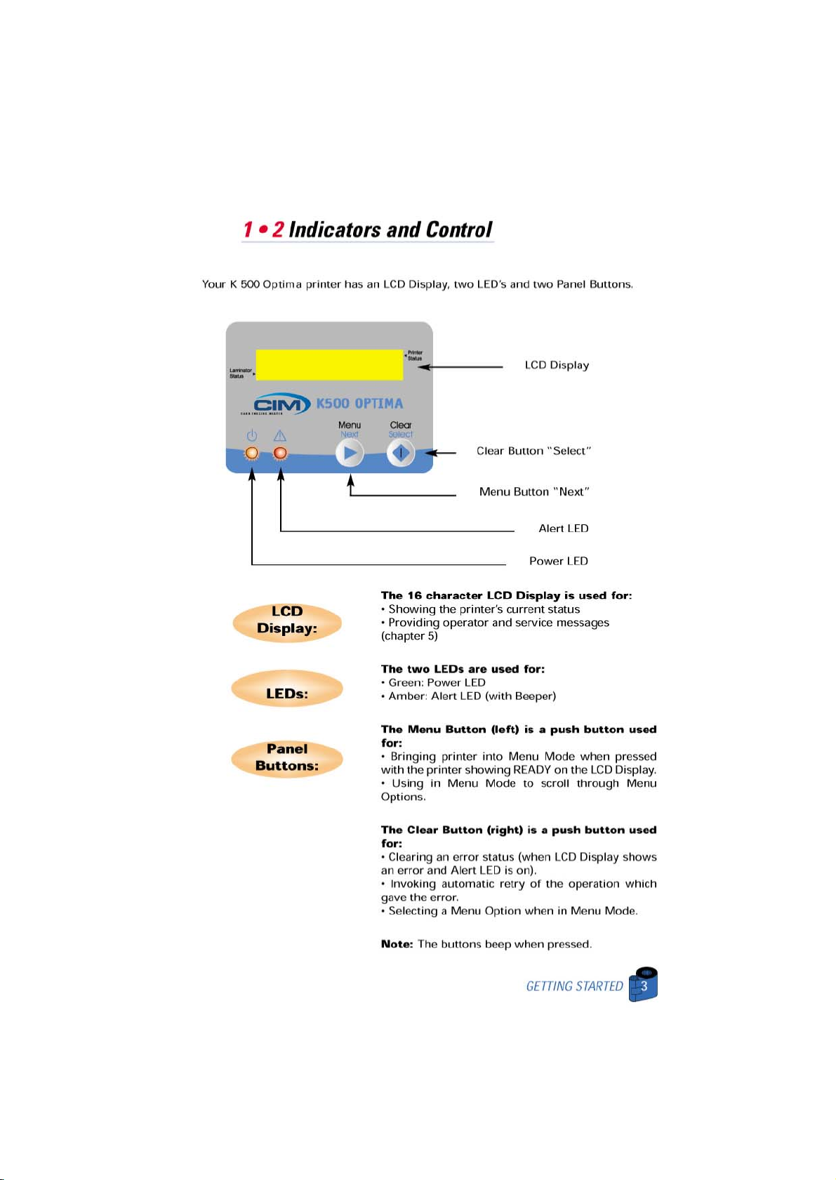
The printer is equipped with an LCD Display and two key buttons which gives access
to printer menus.
When the printer status shows READY, press the Menu button to enter the Menu Mode
Menu Button “NEXT”(left)
Clear Button “SELECT”(right)
When you are in Menu Mode the top line display shows
menu information and the second line of
display clarifies the function of the two “NEXT” and
“SELECT” key buttons relative to the current menu item.
The printer will return to READY Mode if either of
the two key Buttons is not pressed within ten
seconds of entering Menu mode.
PRINTING ST
A
TION:
• PRINTER INFO
• CLEANING MENU
• SELF TEST MENU
• PRINTER DEFAULTS
See next page:
K 500 Optima LCD Menu Tree: Printing Station
*If the printer is equipped with a Magnetic Stripe Encoder
LAMINATOR ST
ATION:
• LAMINATOR INFO
• SELF TEST MENU
• LAM DEFAULTS
Page 25
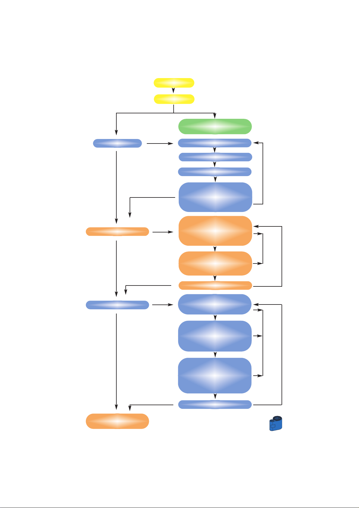
17
OPERATION
READY
Printer info
Menu Lamination
(See Page N°19)
Cleaning Menu
Self Test Menu
Printer Defaults
(follow next page)
Printer Model number
Printer Firmware
Number of Impressions
Reject Box status
To show the number of
cards remaining in the
reject box
Clean Print Head
To Clean the Thermal Print
Head and card transport
system
Clean Mag. Head
To Clean the magnetic
Encoder Head
Go to main Menu
Test Pattern
To print a printer test card
Print Parameters
To print a test card showing
the operating parameter
settings of the printer
Mag. Parameters*
To print a test card showing
the operating parameter
settings of magnetic
encoder.
Go to main Menu
N
S
S
N
N
N
N
N
S
S
S
S
S
S
S
S
S
S
To run printing
To run cleaning
N: NEXT
S: SELECT
Menu Printer
N
N
Page 26
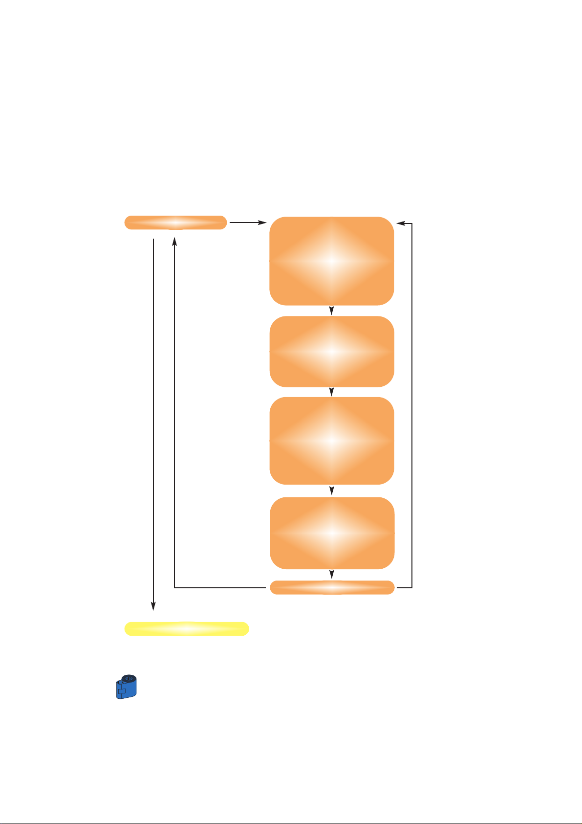
OPERATION
18
Printer Defaults
Ribbon Type
To show the type of ribbon
installed.
It may not match the ribbon
physically installed until the
installed ribbon has been
selected through the driver.
S
Offset X: aa-Y:bb
To show the X print
location offset value in pixels (aa)
To show the Y print
location offset value in pixels
(bb)
Mag. Option: cccc
To show the setting of the
magnetic encoder as (cccc),
which can be:
-HICO (high coercivity)
-LOCO (low coercivity)
-NONE (no encoder present)
Color Parameters
To show the intensity values
of yellow (Y), Magenta (M)
and Cyan (C) panels and
contrast value of black Resin
(K) panel.
Go to main Menu
S
(back to) Menu Printer
N
N
N
N
N
N
Menu Tree: Printing station (continuation)
N: NEXT
S: SELECT
Page 27
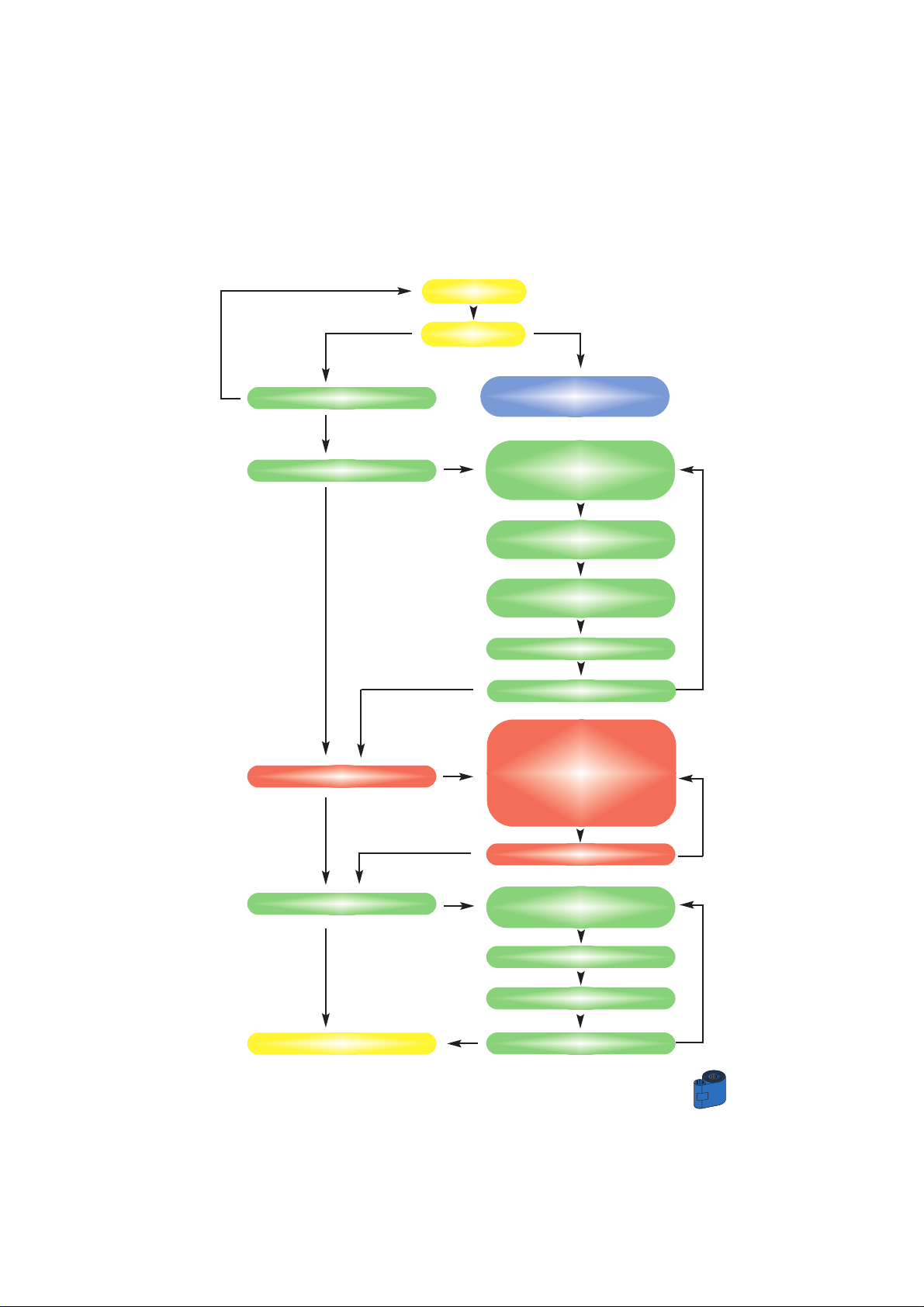
19
OPERATION
READY
Printer info
see page N°17
Menu Lamination
N
N: NEXT
S: SELECT
Temp: 170°C (U)
Shows current setting for
laminator temperature
Laminator Info
Speed: 08.84 (D)
Speed setting
Patch Clear 0.6
Ribbon setting
Firmware: V1.00
LAM CYCLE
Causes a single cycle of the
lamination operation
i.e produces a single sided
lamination on a blank
(unprinted) card.
Selt test menu
Go to main menu
Off. 1st: +100
offset value
Lam Defaults
Off. syn.: +140
Peel off: 90
Go to main Menu
N
N
N
N
N
N
N
N
N
N
Menu Printer
S
N
N
READY
N
S
S
S
S
S
S
Menu Tree: Lamination station
S
Go to main Menu
N
N
N
Page 28

PRINTING A SAMPLE CARD
21
3
P
RINTING A SAMPLE CARD
Printing with the K 500 Optima Printer requires the Windows Printer Driver,
your card design/issuing software or printer command level programming through
the printer interface.
The K 500 Optima Card Printer can be used with any Windows 95/98 or Windows
NT 4.0 software application program, using the drivers provided with the printer.
This section contains information on the printing of a dual-sided card in color
(using the 6-Panel color ribbon YMCKOK) and the Windows Printer Driver.
BEFORE installing updated printer dri ver ver sions,
always delete the existing printer driver version
from your computer.
Page 29

PRINTING A SAMPLE CARD
22
3 ï 1 To install the K 500 Optima Printer Driver in
windows 95/98, use the following steps:
IMPORTANT NOTE: Ensure that your PC printer
port is set to standard mode and also ensure that
you have deleted any previous versions ot this
printer driver. If you have any doubts please
contact your IT department.
This installation uses floppy drive “A” or from CD Rom as the installation drive with
the printer used as stand alone.
❐ Start your computer and then Windows.
❐Insert your “CIM Software” diskette into the drive “A” or CD drive.
❐ Under windows click the Start button, select Settings, then Printers.
❐ Double click on the Add Printer icon and also Next.
❐ Ensure Local Printer is selected and click on Next.
❐ Click on Have disk and then type in “A:\win95” if using the floppy disc
or“D:\win95” if using the CD and click OK.
❐ K 500 Optima CARDPRINTER should be displayed after which click on Next.
❐ Choose LPT1: Standard Printer P ort, click on Next, select Ye s to set as Default
Printer and click on Finish to install.
The Printer wizard will copy the necessary files to the PC for you and the K 500
Optima printer driver installation will be completed.
Page 30

23
PRINTING A SAMPLE CARD
3 • 2 To install the K 500 Optima Printer Driver in
windows 2000/NT4.0:
Ensure that you have administrative privileges to
perform this installation or contact your IT
department.
Set printer as Not Shared for stand alone use.
To install the printer drives follow instructons on the Rainbow CD-ROM
Once the printer driver has been successfully installed, you will need to configure it
for your printer. This driver provides control of several printer features when printing
from Windows applications. These features are accessed through the K 500 Optima
Plastic Card Printer Properties. To access these properties select the K 500 Optima
Printer icon in Printers. Then click File Menu and select Properties.
3 • 3 Set Printer Driver Options:
The K 500 Optima Printer screen appears. Change the options as follows:
❐ On the Printer tab configure the magnetic encoder feature. If your Printer is
equipped with a Magnetic Encoder option, select With Magnetic Encoder
option.
❐ On the Card tab select card orientation:
Landscape or portrait - Select “Landscape”.
❐ On the Ribbon tab, select the Ribbon Type. SelectYMCKOK for the standard
6-panel ribbon.
❐ In the same tab, go to Black Panel area and select Text Only. this option
allows the text printing using the Black Resin Panel from the Color Ribbon.
❐Close the CIM K 500 Optima Printer Properties screen.
Now that you have loaded media and set up the printer driver, the K 500 Optima
Printer is ready to print.
Page 31
PRINTING A SAMPLE CARD
24
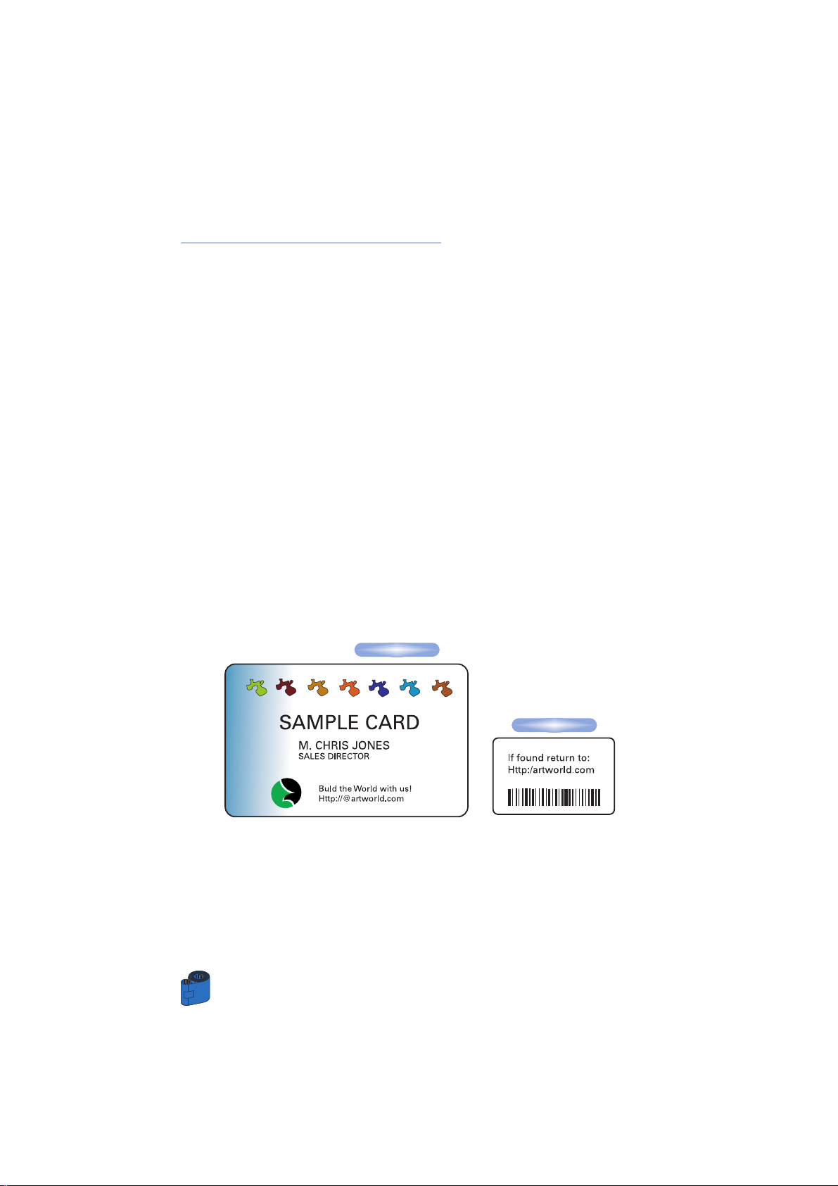
3 • 4 Printing a sample card:
Follow the steps to print your first card
❐Go to the Microsoft Word Software.
❐ If the printer was not selected as the default printer, go to the file menu
and Select Printerand choose CIM K 500 Optima Card Printerin the printer
names list. Then Close the print dialog box.
❐ Come back to file menu and choose Page Setup.
❐Select Paper Sizetab and in Paper Sizechoose Card. Then select the
orientation: “landscape”.
❐Go to Marginstab, Set the Top, Bottom, left and right margins to O (zero)
values.
❐Press OKto close Page Setup window.
❐ The card appears on the screen.
❐Design a card with 2 sides as follows:
❐ Once you are ready to print, go to File and point Print
❐ The printer will feed in a card and start printing (the data download time will
vary depending on the complexity of the card design and the processing speed
of the computer).
❐ Once the printing job is achieved the card is ejected from the printer.
Front Side:
Back Side:
Page 32

25
CLEANING
4
C
LEANING
PROTECT YOUR FACTORY WARRANTY!
The recommended maintenance procedures must be perfor-
med to maintain your factory warranty.
Other than the recommanded cleaning procedures described
in this manual, allow only CIM S.p.A. authorised
technicians to service the K 500 Optima Printer.
NEVERloosen, tighten, adjust, or bend, etc. a part
or cable inside the printer.
NEVER use a high pressure air compressor to
remove particles in the printer.
Page 33
CLEAN PRINTER
Although the CLEAN PRINTER message is
displayed until the cleaning process has been
performed, the printer will continue to operate.
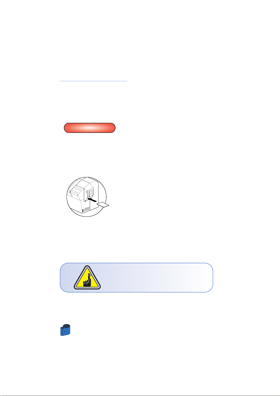
4 • 1 Cleaning System
Your K 500 Optima Printer includes a simple cleaning system using the Pre-Satured
Cleaning Cards provided. The regular use of these cards will clean and maintain important
parts of your printer that cannot be reached: including the Print Head, the Lamination
station and Transport Rollers.
WHEN TO CLEAN
When the LCD screen reports messages.
HOW TO CLEAN
1 • Leave power on.
Open Cover and release Print Head Bracket to
remove ribbon.
Close Print Head Bracket
Close Cover. Remove cards from Card Feeder.
2 • Insert one Pre-Saturated Cleaning Card
(provided) through slot on the side of the Card
feeder Cover.
3 • Press the right panel button for a few seconds.
The card will feed into printer and carry out the
cleaning process. repeat the process with a new
Cleaning card if necessary.
Note: For a printer cleaning prior to the WHEN TO CLEAN signal, press the Left Panel
button until the LCD screen shows “CLEANING MENU”. Press the right Panel button to
select and one more time again to run the cleaning process (Repeat first steps 1 & 2
above).
CLEANING
26
Page 34
27
CLEANING
4 • 2 Cleaning the Print Head
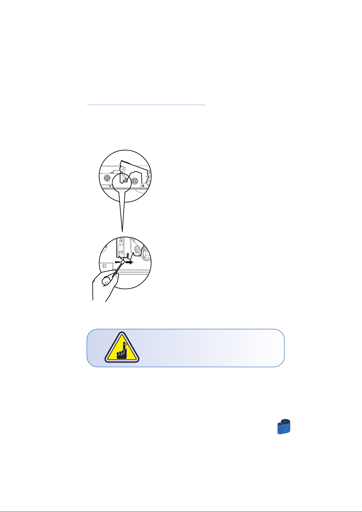
A cleaning using the cleaning system with cards usually suffices. However, a
separate Print head cleaning using swabs can remove more stubborn deposits when
print anomalies persist. To avoid deposits, only use foam-tipped swabs.
1 • Switch power Off, open cover, raise Print Head
and remove the Ribbon.
2 • Clean Print Head by moving alcohol-moistened
swab tip side-to-side across Print Head elements.
Only use moderate force.
Make sure the elements are dry before switching on.
Never use a sharp object to scrape deposits from
the print head. Permanent damage will result.
Page 35
PRINTING A SAMPLE CARD
28
4 • 3 Cleaning the Laminator Rollers
A cleaning using the Cleaning System with cards usually suffices, moreover your
printer is equipped with two cleaning rollers situated before the card enters the
Laminator. The upper roller has a coating that collects any loose particles on the
surface of cards. However, a separate Laminator Station cleaning can remove more
stubborn deposits.
To avoid deposits, only use foam-tipped swabs.
Never touch the rollers with fingers.
WHEN TO MAINTAIN
Cleaning frequency varies with different
environments. Clean when lamination anomalies
persist.
HOW TO MAINTAIN
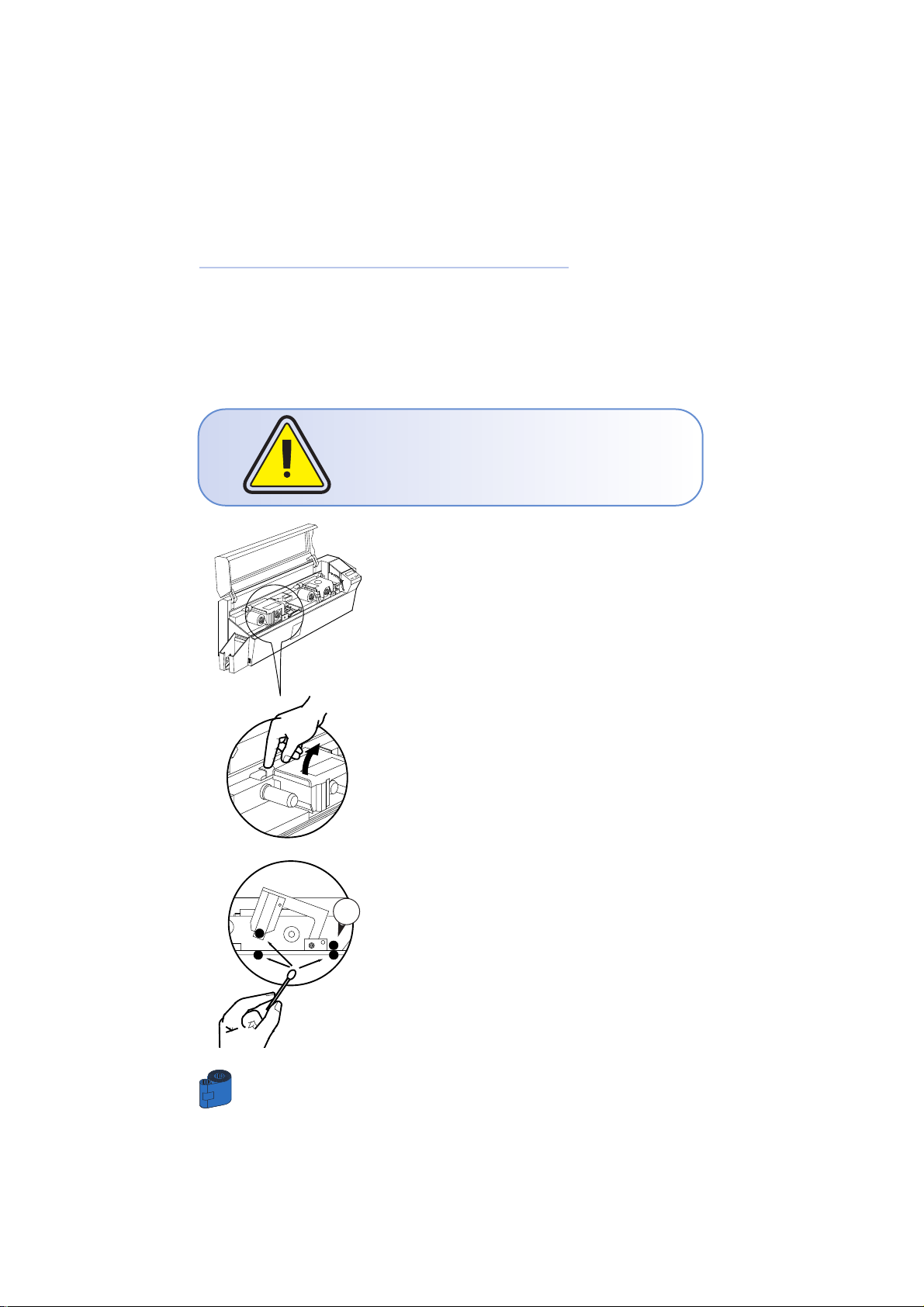
1 • Switch OFF your printer and open cover. Make
sure the Laminator rollers cool down.
2 • Press down on the unlock lever to open the
Laminator braquet.
3 • Clean the two Laminator rollers and the
two transport rollers gently with a swab.
(The above transport roller “1” can be temporary
removed for an easy clean)
4 • Make sure the rollers are dry before Pushing
down the braquet and switching on your printer.
1
Page 36
29
PRINTING A SAMPLE CARD
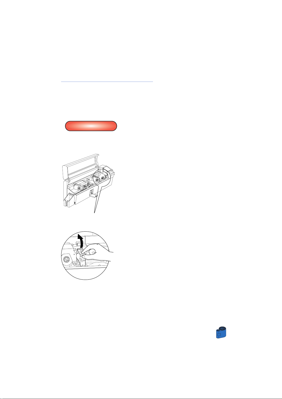
4 • 4 Card Cleaning Cartridge
Your K 500 Optima Printer also has a Card Cleaning Cartridge. This item cleans
the cards entering the printer. To ensure print quality, the cleaning roller requires
periodic replacements.
WHEN TO MAINTAIN
When LCD screen reports message.
Run a printer cleaning first.
(see 4.1 Cleaning System for more instructions).
HOW TO MAINTAIN
1 • Open Cover and locate Cleaning Cartridge
2 • Gently remove Cleaning Cartridge by rotating up
and away from printer.
CLEAN PRINTER
Page 37
CLEANING
30
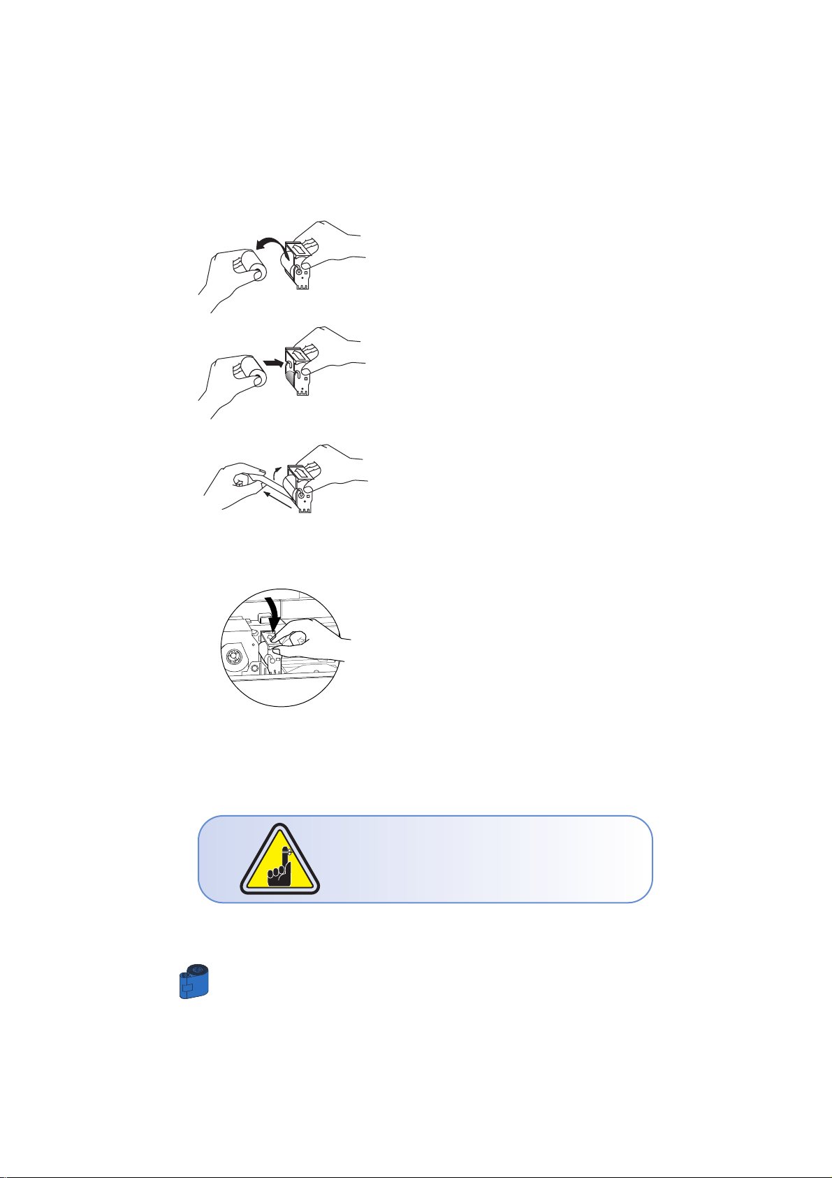
3 • Remove Cleaning Roller from Cartridge and dis-
card.
4 •Install new Cleaning Roller into Cartridge. To
avoid contamination, always hold the Cleaning
Roller assembly by the ends.
5 • Carefully peel off wrapper from new Cleaning
Roller while in Cartridge.
6 • Replace Cartridge into printer. Make sure the
arrow on top of the assembly is facing towards the
rear of the printer. Hook assembly into slot on printer and rotate down. Ensure the assembly locks in
place.
DO NOT touch the roller surface that contacts the
cards.
7 • Close Cover
Although the CLEANING PRINTER message is
displayed until maintenance has been performed,
the printer will cotinue to operate.
Page 38
5
T
ROUBLESHOOTING
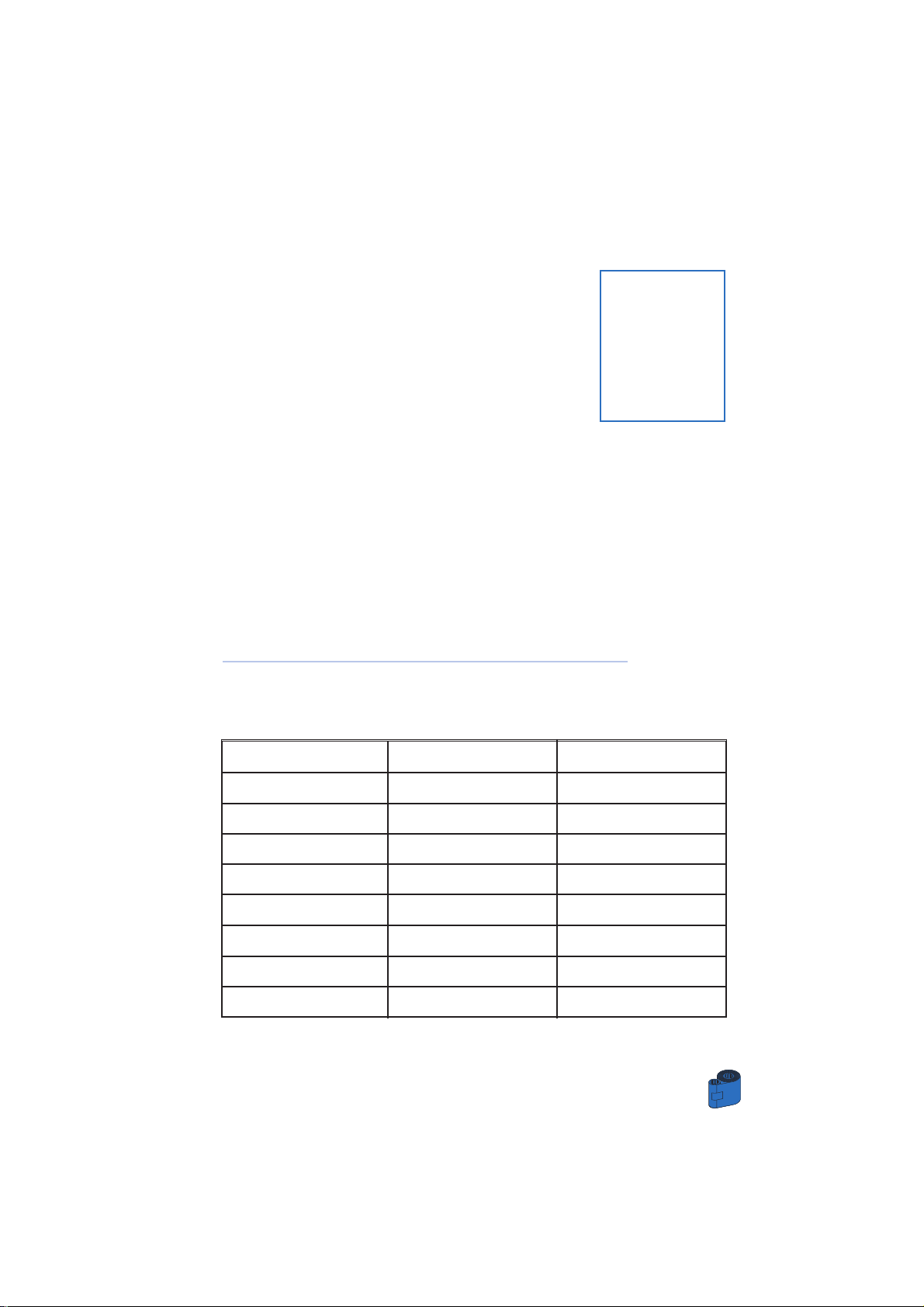
This section offers solutions to potential problems you may experience with your K 500
Optima printer. The table below lists the screen messages that will be displayed
on the printer’s LCD, both during normal operation and to alert operator of any
error conditions. There is also some additional information dealing with quality
issues concerning printing onto cards.
5 • 1Interpreting LCD Display messages
A • About the Printing Station
SCREEN MESSAGE
INITIALIZING
READY
W AIT TEMPERATURE
SELF TEST
DOWNLOADING DATA
PRINTING YELLOW
PRINTING MAGENTA
PRINTING CYAN
MEANING
The printer is performing
an internal test before use
Ready for use
Print Head cool down
mode
Self test card printing
The card data is being
transmitted
The yellow panel is being
printed
The magenta panel is
being printed
The cyan panel is being
printed
ACTION
Wait for the ready message
Wait for card printing to start
31
TROUBLESHOOTING
Page 39
TROUBLESHOOTING
32
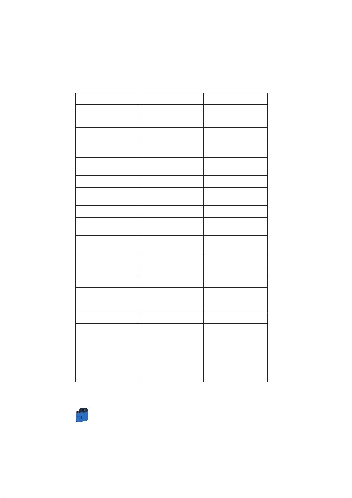
SCREEN MESSAGE
PRINTING BLACK
PRINTING V ARNISH
PRINT HOLOGRAM
CLEAN PRINTER
CLEAN MAG HEAD
CLEANING
REMOVE RIBBON
OUT OF RIBBON
MECHANICAL ERROR
OUT OF CARD
ROTATION ERROR
COVER OPEN
HEAD OPEN
COMMAND ERROR
PARAMETERS ERROR
ENCODING ERROR
MEANING
A monochrome panel is
being printed
The overlay is printing
A hologram overlay is printing
The printer is prompting
operator maintenance
The printer is prompting
operator
The printer is performing an
internal cleaning routine
The ribbon has not been
removed while the cleaning
operation is in progress
The printer ribbon has run out
The printer has an error
moving the card internally
The card feeder is empty
The printer has an error
moving the card in the flip
The cover is open
The print head is not locked
into position
The data being sent from the
host is not recognised
The features of the card are
not recognised
Data cannot be written or read
from the card’ s magnetic stripe
Data cannot be read from the
card’ s magnetic stripe
The reject box is full
The printer cannot detect a
magnetic stripe on the card
ACTION
Carry out the cleaning
procedure as detailed in
section 4 of this manual
Carry out the cleaning
procedure as detailed in
Appendix A of this manual
Remove ribbon
Replace printer ribbon
Remove the jamed card.
Ensure the card is not
out of specification
Add more cards or adjust
the card feeder to accept
the cards
Remove card
Close the cover
Lock the print head in its
lower position
Check that the data is suitable for printing. Try
reprinting a card from
known “good” data
Check the windows driver
options and printer type
Check that the cards are
loaded with the magnetic
stripe in the correct orientation. Check whether high
or low coercivity cards
have been specified. Check
that the data conforms to
ISO specifications. See
Appendix A of this manual
for further information.
Page 40
Ribbon Errors: Check that the print ribbon has not “run out”. Lock and then unlock the
print head assembly; this resynchronises the ribbon automatically. When using a color
ribbon, it should advance automatically so that the leading edge of the yellow panel is
beneath the print head. Ensure that the correct ribbon type has been specified in the
Windows driver.
Card Feed & Mechanical Errors: Ensure that the card thickness adjustment has been
set-up correctly to allow one card to feed.
Magnetic Encoding Errors: Check that the cards are inserted correctly in the printer.
Ensure that the cards are low or high coercivity as required, and are set-up correctly
in the printer driver.
Cleaning Alert: The printer has counted the number of cards printed and has
automatically flagged that a cleaning routine needs to be carried out. (See Chapter 4).
SCREEN MESSAGE
READING ERROR
REJECT BOX FULL
MAGNETIC ERROR
FLASH ERROR
NO ACCESS
MEANING
Data cannot be read from
the card’s magnetic stripe
The reject box is full
The printer cannot detect a
magnetic stripe on the card
ACTION
Check that the cards are
loaded with the magnetic
stripe in the correct orientation. Check whether high or
low coercivity cards have
been specified. Check that
the data conforms to ISO
specifications.See
Appendix A of this manual
for further information.
Empty the reject card box and
press the right panel button
Check the card orientation
Contact your dealer for
technical support
33
TROUBLESHOOTING
Page 41
TROUBLESHOOTING
34
B • About the Laminator Station
SCREEN MESSAGE
INITIALISING
READY
COVER OPEN
ROTATION ERROR
LAMINATING
OUT OF RIBBON
MECHANICAL ERR
TEMPERATURE ERR
WARMING UP
RIBBON FAILURE
STANDBY MODE
MEANING
The printer is performing
an internal test before use
Ready for use
The cover is open
The printer has an error
moving the card in the flip
The printer is processing a
lamination
The printer ribbon has run
out
the printer has an error
moving the card internally
The printer has detected a
temperature error
A lamination command has
been sent and the temperature has not reached +/- 7°C
of the recommended temp.
The film is glud to the card
during the cool down
period.
Laminator power reduced.
ACTION
Wait for the ready message
Close cover
Remove card
Wait for the laminated card
Load a new ribbon
Remove the jamed card.
Ensure the card is not out of
specification.
Proceed an initialization by
switching Off and On.
Wait until the printer has
reached the recommended
temperature
Open laminator bracket.
Remove card.
Close laminator bracket.
Page 42

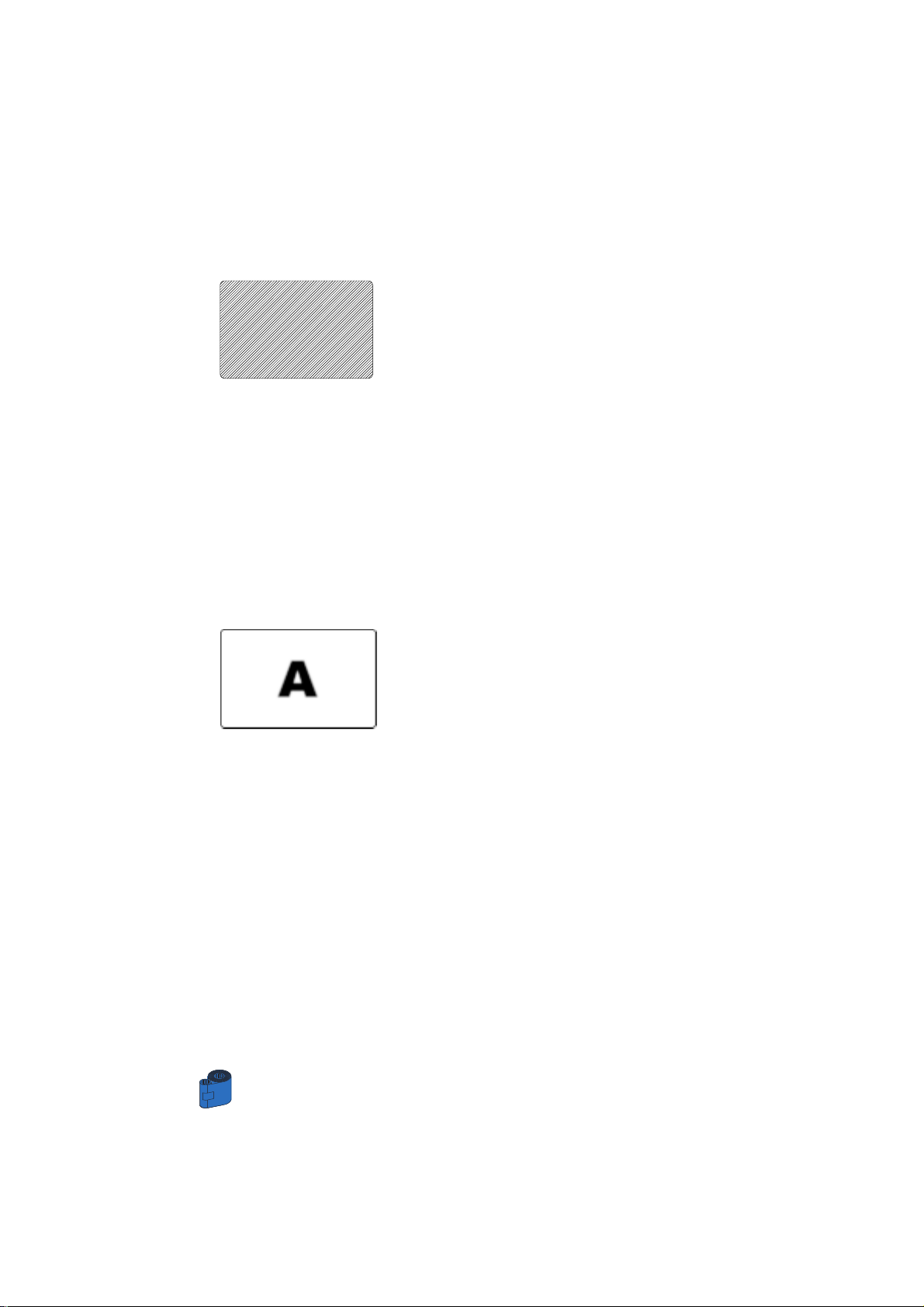
5 • 2 Print Quality Issues
This section will help you resolve print quality problems. The print quality is
dependent on several factors. The two most important factors that will increase your
print quality are cleanliness and card stock. To diagnose and fix print quality problems,
follow the troubleshooting procedure below:
• Small spots appear on the printed card with a non-printed area or a different color.
Possible Cause
A • Contamination on the card surface.
B • Dust inside the printer and/or dirty Cleaning Roller.
>> Solution
A1 • Check that cards are stored in a dust free environment
A2 • Use a different supply of cards.
B1 • Perform a Cleaning of the printer (see Cleaning section).
B2 • Replace Cleaning Roller (see Cleaning section)
• There are non-printing horizontal lines (white) on the card surfaces.
Possible Cause
A • Ribbon is not correctly positioned.
B • Print Head may be dirty.
C • Print Head elements may have been damaged
(e.g. scratched or burnt).
>> Solution
A1 • Open cover and press down the Print Head Unlock Lever to open the Print
Head carriage. The Print Head will move up.
A2 • Check that the ribbon is properly rolled onto the ribbon cores and there
are no wrinkles in the ribbon.
A3 • Push down on the Lock Lever until an audible “click” signals the lock ed-
down position.
A4 • Ribbon will automatically synchronize.
A5 • Print again.
B1 • Perform a Cleaning of the Print Head (see 4 • 2 Cleaning the Print Head).
C1 • Call service for Print Head replacement information.
35
TROUBLESHOOTING
Page 43
TROUBLESHOOTING
36
• Printing shows very pale or inconsistent results.
Possible Cause
A • Ribbon have been stored improperly or is damaged.
B • Cards may not meet specifications.
C • Contrast and/or Intensity may be set to values
which are too high.
D • Dust or embedded contamination on elements of
the Print Head.
>> Solution
A1 • Change ribbon and print again.
B1 • Use a different supply of cards.
C1 • Adjust Contrast and/or Intensity values in software.
D1 • Perform a Cleaning of the Print Head (see 4 • 2 Cleaning the Print Head).
• Printing shows blurry printed image.
Possible Cause
A • Ribbon may not be correctly positioned.
B • Ribbon may not synchronized on the correct color
panel position.
C • Cards may not meet specifications.
D • Dust inside the printer and/or dirty Cleaning Roller.
>> Solution
A1 • Open cover and press down the Print Head Unlock Lever to open the Print
Head carriage. The Print Head will move up.
A2 • Check that the ribbon is properly rolled onto the ribbon cores.
A3 • Push down on the Print Head Lock Lever until an audible “click” signals
the locked-down position.
A4 • Ribbon will automatically synchronize.
A5 • Print again.
B1 • Open cover and press down the Print Head Unlock Lever to open the Print
Head carriage. The Print Head will move up.
B2 • Push down on the Print Head Lock Lever until an audible “click” signals
the locked-down position.
B3 • Ribbon will automatically synchronize.
B4 •Print again.
C1 • Use a different supply of cards.
D1 • Perform a cleaning of the Print Head (See 4 • 2 Cleaning the Print Head).
D2 • Replace Cleaning Roller (See 4 • 3 Cleaning Cartridge).
Page 44

• No printing on the card.
Possible Cause
A • Ribbon may not be installed in the printer.
B • Cards may not meet specifications.
C • Cable on Print Head may be disconnected.
D • Print Head elements may be scratched or burnt.
>> Solution
A1 • Check for ribbon in the printer.
B1 • Use a different supply of cards.
C1 • Power off the printer and check the Print Head cable connections.
D1 • Call Service for Print Head replacement information.
For optimum print quality, always keep cover of
the printer closed except during ribbon loading
and card thickness control procedures.
The card flipper will not operate and an error will
be indicated if you try to flip a card with the cover
open.
37
TROUBLESHOOTING
Page 45

39
TECHNICAL SPECIFICATION
6
TECHNICAL SPECIFICATIONS
General • High speed printing & laminating
YMCK & 1.0 mil lamination 110 cards per hour
YMCK & 0.6 mil lamination 120 cards per hour
YMCK-K & 1.0 mil lamination 95 cards per hour
YMCK-K & 0.6 mil lamination 105 cards per hour
• Small footprint
•Windows Dri vers for 95/98/2000 and NT 4.0
• One year printer warranty
• One year print head warranty`
Color Printing • Color dye sublimation or monochrome thermal
transfer printing
• 300 dpi (11.8 dots/mm) print resolution
• Edge to edge printing standard
Bar Code • Code 39
• Code 128 B & C with & without check digit
• 2 of 5 & 2 of 5 industrial
• UPCA
• EAN8 &EAN13
• PDF 417 2D bar code and other symbologies
available via Wincard Classic utility tool (option)
Fonts • Resident: Arial Normal 10 0, Arial Bold 100
•True Type fonts available via Windows Dri ver
Cards •Types PVC, Composite
• Card width/length: ISO CR-80 - ISO 7810,
2.125” (54mm) by 3.375” (86mm)
• Option: Magnetic Stripe - ISO 7811
• Option: Smart Card - ISO 7816-2
•Card thickness: 1 0mil (0,25mm) to 50mil (1,25mm) fo r
printing only and 0,8mm for printing and lamination.
• Card Feeder capacity: up to 300 cards (10mil), up to
100 cards (30mil)
• Card Output Hopper capacity: 300 cards (10mil),
up to 100 cards (30mil)
Page 46
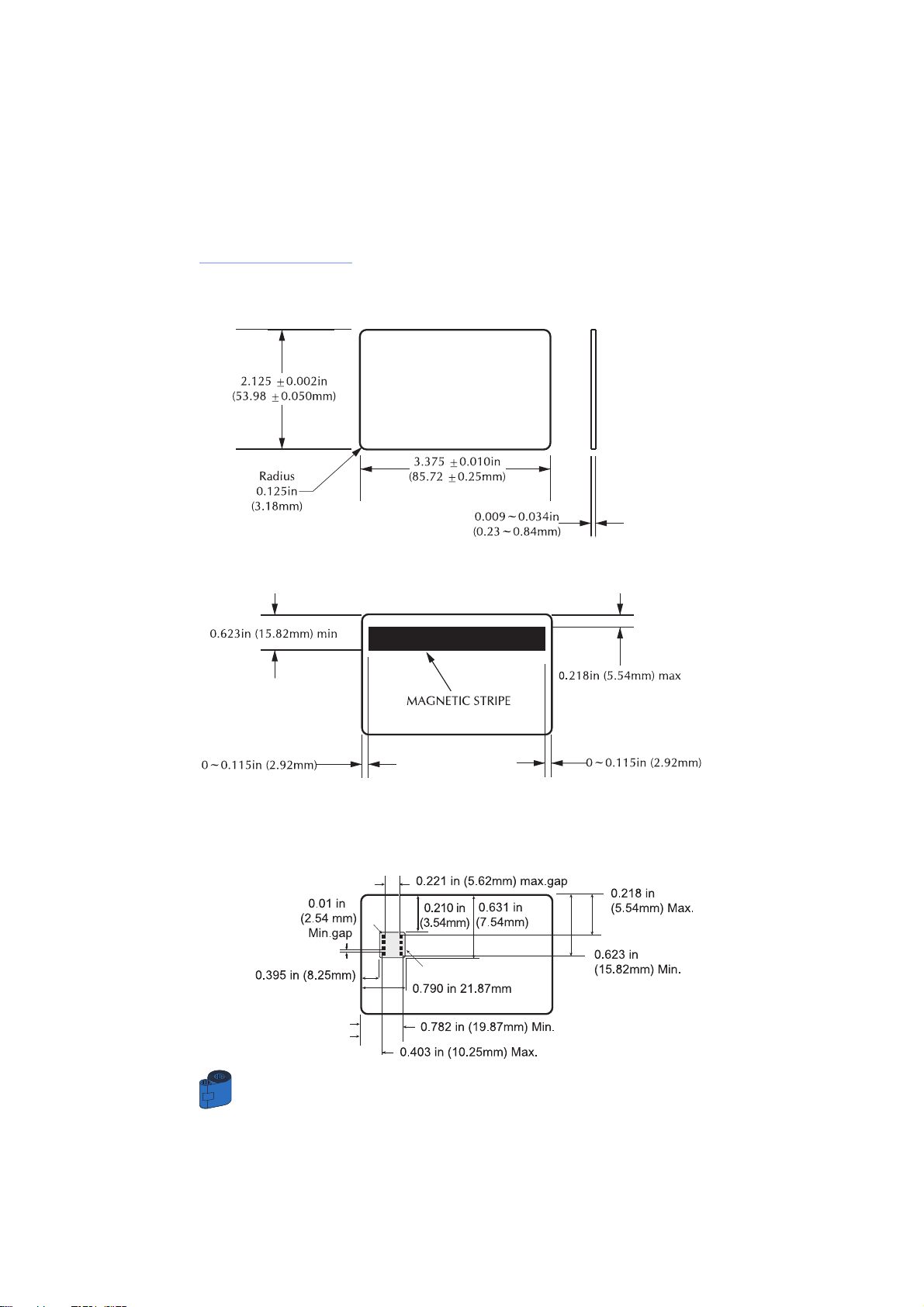
CARD DIMENSIONS
ISO STANDARD DIMENSIONS FOR PLAIN CARD
ISO STANDARD DIMENSIONS FOR MAGNETIC STRIPE CARD
CHIP POSITION FOR SMART CARD
TECHNICAL SPECIFICATION
40
Page 47

Ribbons • Monochrome: 1500 cards/roll
• Monochrome colors: back, red, blue, green, yellow,
silver, gold, white.
• K-resin + O: 800 cards/roll
• K-dye + O: 800 cards/roll
•YMC: 300 cards/roll
•YMCK: 250 cards/roll
•YMCK-K: 200 cards/roll
•YMCKO: 350 cards/roll
•YMCKOK: 250 cards/roll
Patches • Clear Patch 1 or 0.6 mil
• Clear Patch for mag. stripe 1 or 0.6 mil
• Clear Patch for smart card 1 or 0.6 mil
• Hologram Pcard Patch 1 or 0.6 mil
• Advantage seal Pcard image Patch 1 mil
• Hologram Pcard full overlay
•Varnish full overlay
Overlay V ar nish •Thermal transfer
• 4 microns thick
• Clear and holographic options:
- Clear
- Genuine/Secure Hologram
- Custom Hologram
Interfaces • Centronics Parallel Standard
• USB port (Optional)
Mechanical •Width: 31,69” (805mm*)
• Depth: 9,25” (235mm*)
• Height: 10,43” (265mm*)
•Weight: 47,28 Ibs (21,45 kg)
Electrical • 110 ~ 230 Volts AC, 60 ~ 50 Hz
• FCC Class A, CE, UL, and CUL approved
Environmental • Operating Temperature: 60 to 86°F (15 to 30°C)
• Operating Humidity: 20 to 65% non condensing
• Storage Temperature: -23 to 158°F (-5 to 70°C)
• Storage Humidity: 20 to 70% non condensing
•Ventilation: Free air
Dye sublimation printing requires dye sublimation ribbons,with either black or cyan,
magenta, and yellow (plus black resin) panels.
*Measured without card output hopper.
Options • USB port
• Smart card Contact Station (0.76mm cards only)
• Magnetic Encoder (0.76mm cards only)
• Cleaning supplies
41
TECHNICAL SPECIFICATION
Page 48
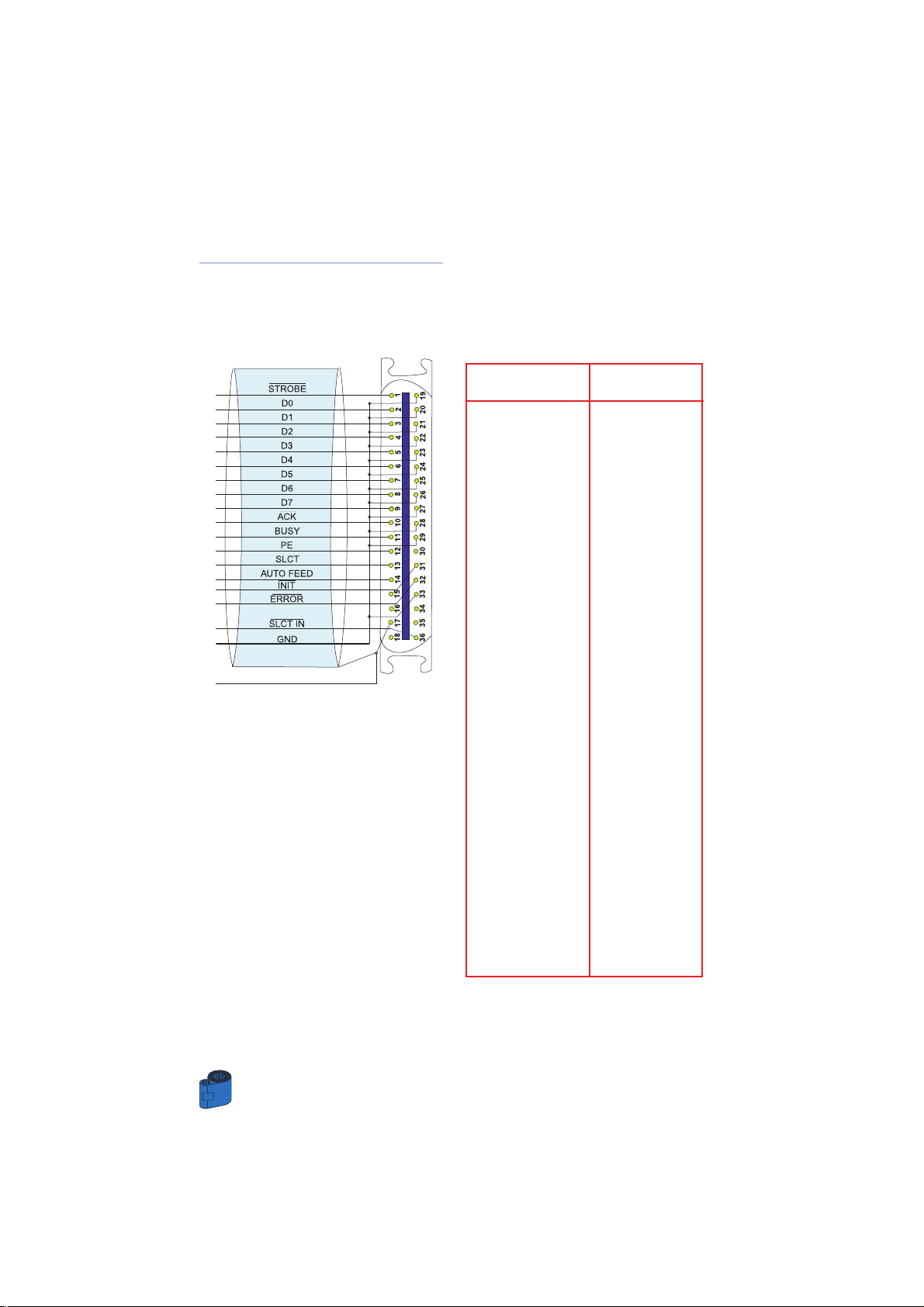
CENTRONIC CABLE INTERFACE
The above drawing shows the required connections to use the printer centronic interface.
TECHNICAL SPECIFICATION
42
Printer Pin Lign Name
1 -STROBE
2DO
3D1
4D2
5D3
6D4
7D5
8D6
9D7
10 -ACK
11 -BUSY
12 PE
13 SLCT
14 -AUTO FEED
32 -ERROR
31 -INIT
36 SLCT IN
19-30-33 GND
Note: The printer pins number 15, 16, 18, 30, 34, 35 are not connected.
Page 49

43
APPENDIX A
A
APPENDIX
Magnetic Card Stripe Encoder
This section contains information on the additional operations of the K 500 Optima
Printers with Magnetic Card Stripe Encoder.
(See Chapter 2 for location.)
INTRODUCTION
Operation and maintenance requirements for the K 500 Optima Printer with the
optional magnetic card stripe encoder.
(See Chapter 2 for location.)
The magnetic encoder can be set for either high or low coercivity.
Page 50
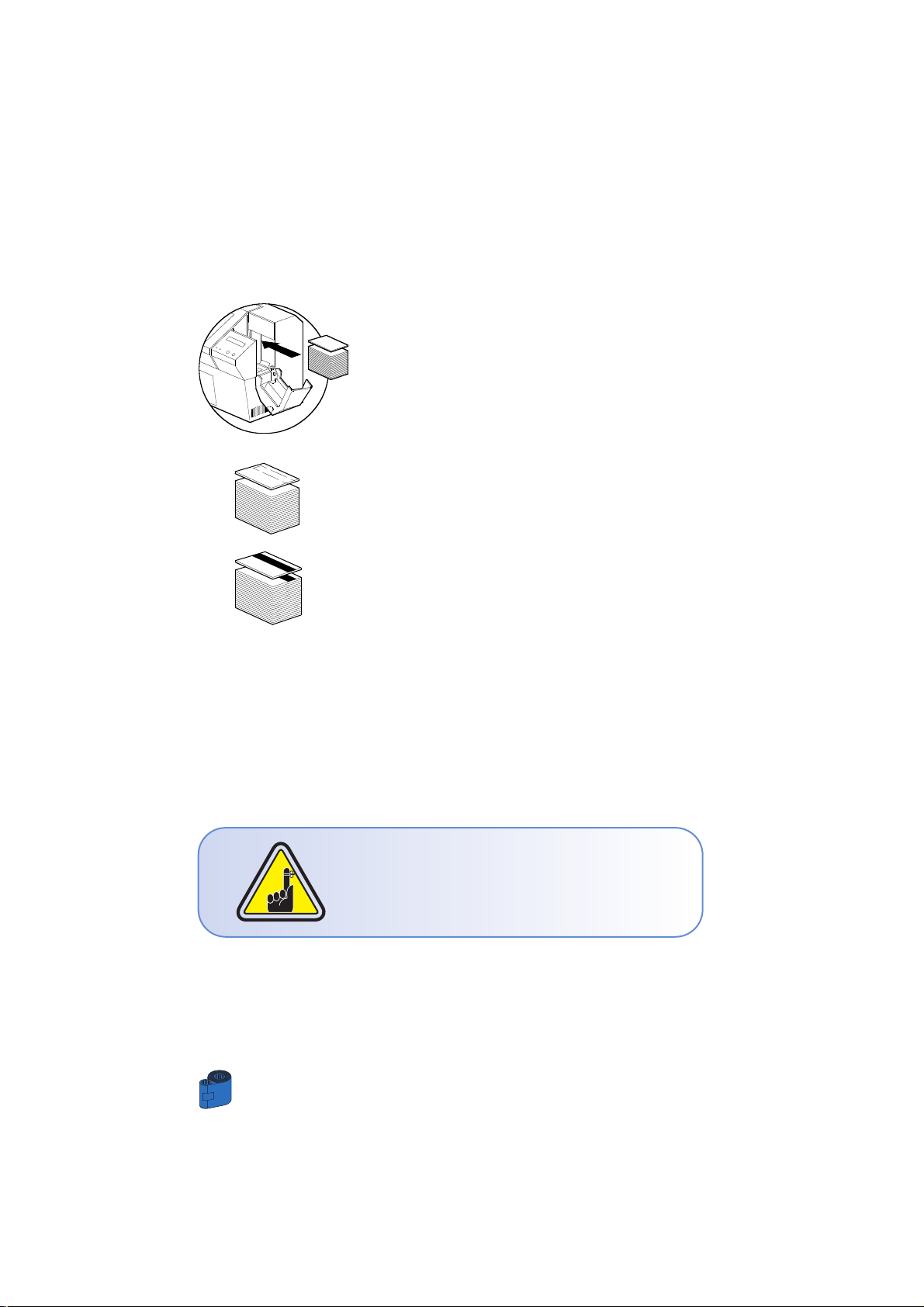
A • MEDIA LOADING ORIENTATION
The magnetic encoder is a factory installed item
with the read/write head positioned below the card
path, available with HICO encoding or LOCO encoding.
When loading cards into the Card Cartridge, please
ensure that the magnetic stripe is facing down and
closest to the rear.
Also available are Printer models with the Magnetic
Read/Write head positioned above the card path,
with HICO encoding or LOCO encoding.
When loading cards, please ensure that the
magnetic stripe is facing up and closest to the rear.
Note:
M1 = Stripe Down HICO M3 = Stripe up HICO
M2 = Stripe Down LOCO M4 = Stripe up LOCO
approved HICO & LOCO PVC cards are available.
ONLY USE cards that comply with ISO 7810 & 7811
standards for magnetic stripe cards. The magnetic
stripe must be flush to the surface of the card to
work properly. Never use cards which have
taped-on magnetic stripes.
APPENDIX A
44
Page 51
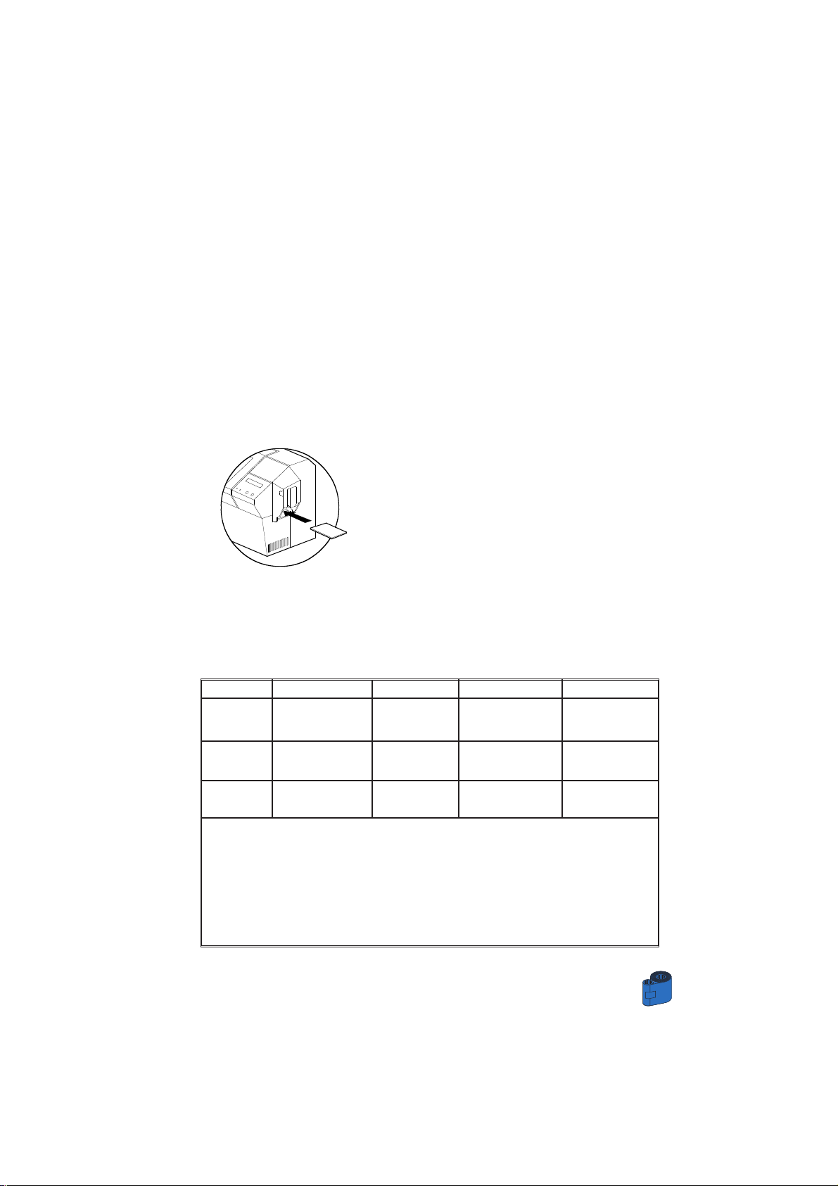
B • MAGNETIC ENCODER CLEANING
There exists two different processes to clean the Magnetic stripe Encoder.
The first process consists of a standard cleaning of the printer. This cleans the most
important parts of the printer; including the print Head, Transport Roller and Magnetic
Stripe Encoder (refer to chapter 4 “Cleaning” for more instructions.)
The second process consist of a cleaning of the Magnetic Encoder using the Menu
Button from the LCD Display.
To access the Magnetic Cleaning Menu proceed as below:
1 • Leave power on.
2 • Remove cards from the card feeder.
3 • Insert one presaturated card (provided) through
slot on the side of the Card Cartridge.
4 • Press the Menu button until the LCD screen
shows CLEANING MENU.
5 • Press the Select button to select.
6 • Press the Menu button again until the LCD screen
shows CLEAN MAG HEAD.
7 • Run this operation by pressing the select button.
ISO STANDARD ENCODING
45
APPENDIX A
Track # Field Separator Track density Valid Characters # of characters
1 ^ 210BPI* Alphanumeric 79***
(ASCII 20 - 95**)
2 = 75BPI* Numeric 40***
(ASCII 48 - 62)
3 = 210BPI* Numeric 107***
(ASCII 48 - 62)
* Bit per inch
** Except the “?” character
*** Including Start, Stop and LRC characters. Also note that these 3 characters are
automatically managed by the magnetic encoder according to the ISO Standard norms.
NOTE:Refer to the Card Printer Programmer’s Manual for complete programming information.
Page 52

APPENDIX B
46
B
APPENDIX
Smart Card Contact Station
This section contains information on the additional operations of the K 500 Optima
Printers with Smart Card Contact Stations.
(See Chapter 2 for location.)
INTRODUCTION
Your K 500 Optima may be equipped with an optional Smart Card contact
station.
Smart Cards can store fingerprints, voice recognition patterns, medical records and other
such data. This printer model basically responds to commands that position the cards
to the contact station, where the printer connects the pins to the contacts connector on
the Smart cards.
An external “encoder/reader” is necessary for programming Smart Cards (ISO 7816).
All other printer operations remain the same as the standard K 500 Optima model.
Page 53
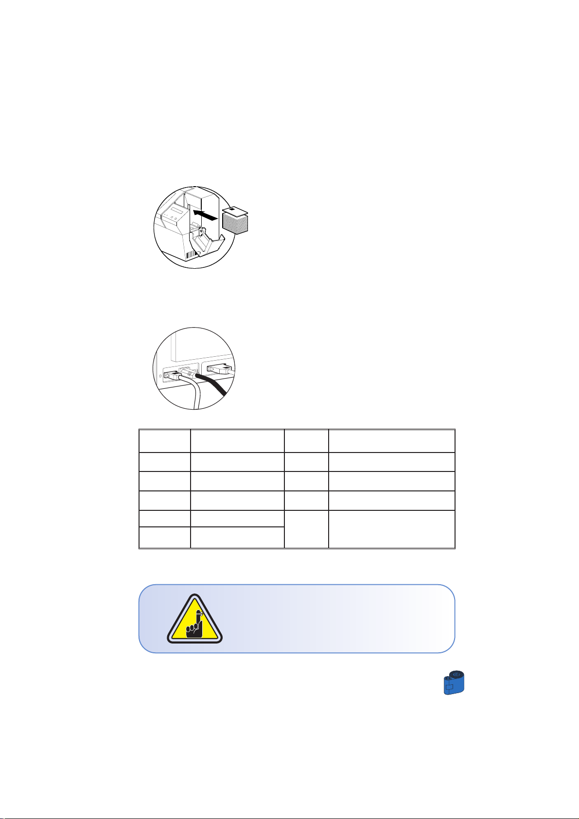
DB - 9 SMART CARD DB - 9 SMART CARD
PINS CONTACT POINTS PINS CONTACT POINTS
1 CI (VCC) 6 C6 (Vpp)
2 C2 (Reset) 7 C7 (I/O)
3 C3 (Clock) 8 C8 (RFU)
4 C4 (RFU)
5 C5 (GND)
9 (GND when chip is at station)
A • MEDIA LOADING ORIENTATION
Position the cards with the Smart Card Chip at the
top of the card and towards the printer.
B • SMART CARD CONTACT STATION INTERFACE
When a command to the parallel printer interface
sends a card to the Smart Card Contact Station, the
printer connects the Smart Card Contact Station to
the female DB-9 connector on the rear of the printer.
An attached external Smart Card Programmer can
be used to program Smart card chips
Refer to the Card printer programmer’s Manual for complete programming information.
DO NOT position printing over the Smart Card Chip.
47
APPENDIX B
Page 54

Page 55

INDICE ALFANUMERICO
Timbro rivenditore Sales Mark
CIM S.p.A. Head Quarters
Via O. Serra, 2
40012 Calderara di Reno Bologna - ITALY
Tel. +39 051 64.65.011
Fax + 39 051 64.65.012
E-mail: [email protected] www.cimitaly.it
CIM USA Inc. - Americas
1912 N.W. 84th Avenue
Miami, FL 33126 - USA
Tel. + 1 305.639.30.40
Fax. + 1 305.639.30.60
[email protected] www.cim-usa.com
CIM S.p.A. Head Quarters
Via O. Serra, 2
40012 Calderara di Reno Bologna - ITALY
I-270 T 1000 PROREV. 04.2001
Tel. +39 051 64.65.011
Fax + 39 051 64.65.012
E-mail: [email protected] www.cimitaly.it
Timbro rivenditore Sales Mark
 Loading...