

Page 1

SONARtrac®
PROCESS MONITORING
SYSTEM
QUICK START GUIDE
CiD RA Cor p o r a t i o n
CiD RA Cor p o r a t i o n
CiD RA Cor p o r a t i o n
Tel: 203 265 0035
Tel: 203 265 0035
Tel: 203 265 0035
50 Barnes Park North
50 Barnes Park North
50 Barnes Park North
Fax: 203 294 4211
Fax: 203 294 4211
Fax: 203 294 4211
Wallingford, CT 06492
Wallingford, CT 06492
Wallingford, CT 06492
www.cidra.com
www.cidra.com
www.cidra.com
Page 2

Page 3

Table of Contents
1 INTRODUCTION................................................................................................................ 1-1
1.1 Purpose......................................................................................................................1-1
1.2 Sensor Head Description and Function......................................................................1-1
1.3 Transmitter Description and Function ........................................................................1-1
1.4 CiDRA Corporation Contact Information....................................................................1-1
2 TRANSMITTER LAYOUT..................................................................................................2-1
2.1 Transmitter Illustration................................................................................................2-1
3 TRANSMITTER STARTUP AND OPERATION.................................................................3-1
3.1 Initial Start-up.............................................................................................................3-1
3.2 Initial Diagnostic Checks............................................................................................3-2
3.2.1 Process On-Line.................................................................................................3-2
3.2.2 Process Off-Line.................................................................................................3-6
3.3 Operating Menu Setup...............................................................................................3-7
3.3.1 VF-100 System Initial Setup...............................................................................3-7
3.3.2 VF/GVF-100 System Initial Setup.......................................................................3-9
4 HART COMMUNICATIONS...............................................................................................4-1
4.1 Introduction.................................................................................................................4-1
4.2 Setup..........................................................................................................................4-1
4.2.1 Internal Vs External Current Source...................................................................4-1
4.2.2 4-20mA Transmitter and DCS Connections.......................................................4-2
4.2.3 Fisher-Rosemount Model 275 Handheld HART Terminal..................................4-2
4.2.4 HART Activity Indicator ......................................................................................4-3
4.2.5 Transmitter Front Panel Menu Inputs.................................................................4-3
4.2.6 Transmitter Configuration File HART Settings ...................................................4-4
4.3 HART Troubleshooting ...............................................................................................4-5
4.3.1 HART Master Does Not Connect to SONARtrac................................................4-5
4.3.2 Primary Value Read Using HART Does Not Match SONARtrac........................4-5
4.3.3 Connection to SONARtrac Is Intermittent...........................................................4-5
4.4 HART Commands......................................................................................................4-6
List of Figures
Figure 1 Transmitter Layout: Transmitters With Non-Pluggable Terminal Blocks................2-1
Figure 2 System Start Display..............................................................................................3-1
Figure 3 SONARtrac Front Panel Menu Power Select Setting Internal and External ..........4-1
Figure 4 Transmitter Connector Board 4-20mA Connections ..............................................4-2
Figure 5 Transmitter to DCS Wiring for Internal and External Power Select........................4-2
Figure 6 SONARtrac Transmitter and HART 275 Communicator ........................................4-2
Figure 7 Transmitter Indicator of HART Activity...................................................................4-3
Figure 8 HART Universal Command Revision .....................................................................4-3
Figure 9 HART Polling Address............................................................................................4-3
Figure 10 HART Preambles and Response Preambles.........................................................4-4
List of Tables
Table 1 Keypad Functions in Operational and Menu Modes ..............................................3-2
Copyright © 2007 CiDRA Corporation Page i
20984-01 Rev 01
Page 4

*** This Page is Blank ***
Copyright © 2007 CiDRA Corporation Page ii
20984-01 Rev 01
Page 5

1 INTRODUCTION
1.1 Purpose
The purpose of this document is to provide an overview of the CiDRA
SONARtrac system startup and operation. It is not intended to
replace reading the full manual.
This overview and the installation manual are intended to be general
installation guides for the SONARtrac Process Monitoring Systems.
They are not intended to cover the installation details for every
process due to the wide variety of applications and processes on
which the system can be used. In all cases, local safety and operating
practices should take precedence over instructions contained within
these documents.
1.2 Sensor Head Description and Function
The SONARtrac sensor head contains no moving parts. The sensor
head includes a sensor band and a fiberglass or stainless steel cover
assembly to protect the sensor band. The sensor band is wrapped
around and clamped onto the process pipe. A multi-conductor cable
electrically connects the sensors to an electronic module mounted in
the cover assembly. Signals from the electronic module exit through a
connector mounted to the outer surface of the cover assembly.
1.3 Transmitter Description and Function
The SONARtrac transmitter receives electrical signals from the sensor
head. The signals are processed using sonar array processing
firmware that displays the calculated results on an integral LCD
screen. Results can be transmitted using the 4–20mA analog output,
pulse output, alarm output, MODBUS / RTU RS-485/232 interface or
optional Foundation Fieldbus™. The electronic assembly is housed in
a rugged NEMA 4X enclosure.
1.4 CiDRA Corporation Contact Information
CiDRA Corporation
50 Barnes Park North
Wallingford, CT, USA 06492
Telephone: 1-203-265-0035
1-877-243-7277 (US and Canada)
Email: www.cidra.com
Sales Support: [email protected]
Customer and Technical Support: [email protected]
Copyright © 2007 CiDRA Corporation Page 1-1
20984-01 Rev 01
Page 6

*** This Page is Blank ***
Copyright © 2007 CiDRA Corporation Page 1-2
20984-01 Rev 01
Page 7
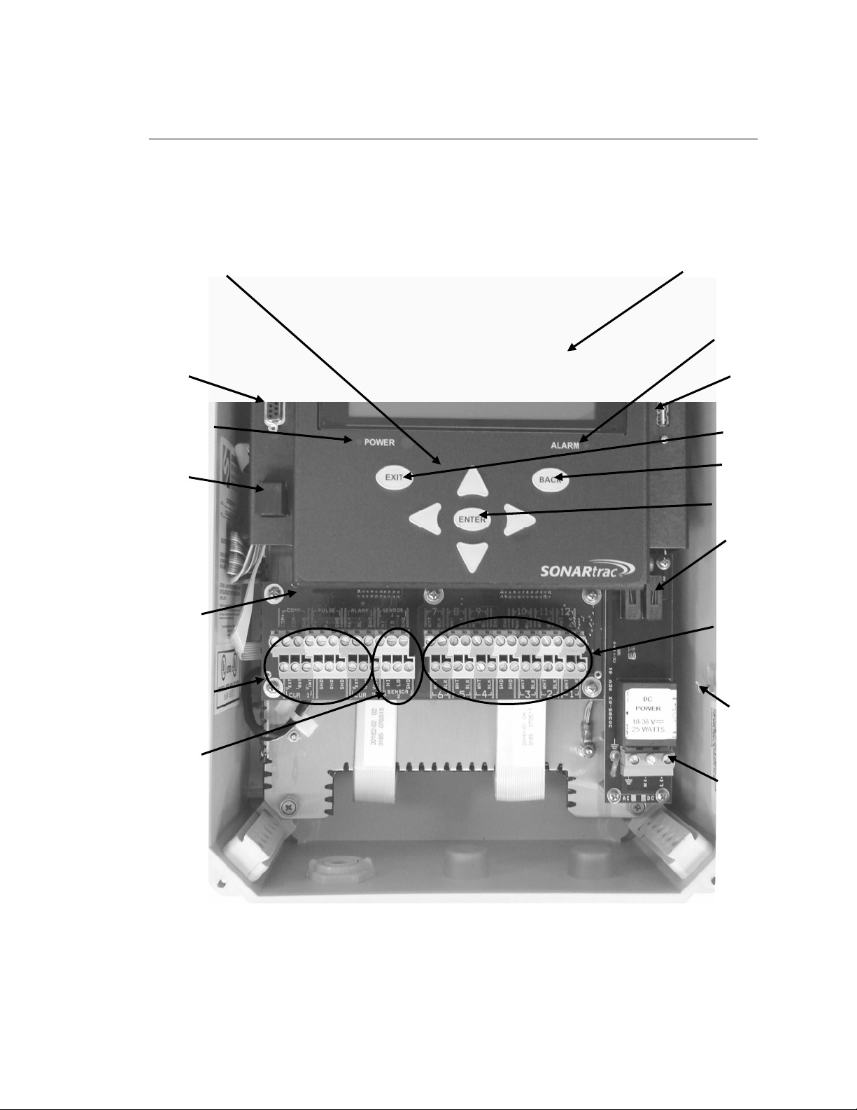
2 TRANSMITTER LAYOUT
2.1 Transmitter Illustration
Navigation keys
The following figure illustrates the SONARtrac transmitter.
LCD display
Serial port
System operating
LED
Ethernet port
Reset button (top
edge of board)
Output terminals
Alarm mode
LED
USB Port
EXIT key
BACK key
ENTER key
Fuses
Sensor head
input terminals
Spare fuse
External sensor
input terminals
Electrical
power
terminals
Figure 1 Transmitter Layout: Transmitters With Non-Pluggable Terminal Blocks
Copyright © 2007 CiDRA Corporation Page 2-1
20984-01 Rev 01
Page 8

*** This Page is Blank ***
Copyright © 2007 CiDRA Corporation Page 2-2
20984-01 Rev 01
Page 9

3 TRANSMITTER STARTUP AND OPERATION
3.1 Initial Start-up
At initial power up the Green LED will light and the transmitter will
display startup progress; load firmware into the system, load system
parameters, and the heartbeat indicator will activate as the transmitter
begins to collect data from the sensor head. Once startup is
complete, the display will clear and begin displaying measurements.
The following figure illustrates an initial system startup screen.
System is
starting
Firmware
revisions as
they load:
F: FPGA
D: DSP
P: PreAmp
Startup >>>>>>>>>>>>>>>>
010.001.009.1
IP Address
D 01.00.23 P
/
e I: Interfac
Figure 2 System Start Display
The SONARtrac display has 2 distinct modes: the operational mode
Mode and
heartbeat
where the measured parameters are displayed and the menu mode
where various system parameters can be set. In each of these modes
the keypad will have different functions. The following table shows the
function of each key in the keypad depending on the display mode.
Menu traversal rules are based on the following table.
Copyright © 2007 CiDRA Corporation Page 3-1
20984-01 Rev 01
Page 10
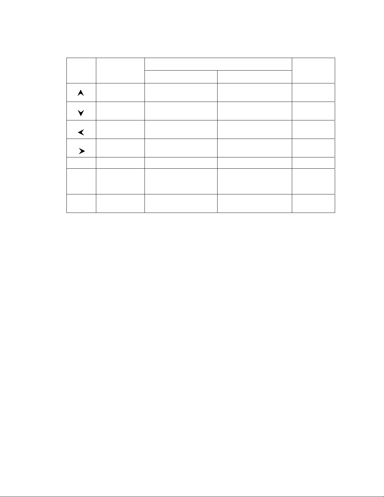
Key
Up
Down
Left
Right
EXIT
BACK
ENTER
Operational
Mode
Enter Menu
Mode
Enter Menu
Mode
Enter Menu
Mode
Enter Menu
Mode
Clears Alarm Exit Menu Exit Menu Exit Dialog
Enter Menu
Mode
Enter Menu
Mode
Table 1 Keypad Functions in Operational and Menu Modes
Navigation Editing
Cycle Menu Item
Cycle Menu Item
NA Change cursor position Exit Dialog
NA Change cursor position Exit Dialog
Exit Menu from Main
Menu or back up one
level in menu tree
Change menu level or
start editing
Menu Mode
3.2 Initial Diagnostic Checks
3.2.1 Process On-Line
Change current value at
cursor position
Change current value at
cursor position
Exit editing mode
without saving
Exit editing mode and
save current value
Dialog
Box
Exit Dialog
Exit Dialog
Exit Dialog
Exit Dialog
The SONARtrac meter can be installed and configured with the
process in operation. Ideally, configuration is made with the process
operating at normal flow rates and operating conditions.
If the process is on-line (flowing) the following system checks should
be made.
3.2.1.1 Sensor Test
A Sensor Test all ‘ON’ sensors. (Individual sensors may be turned off
in the ‘Customize>Sensor Setup>State’ menu. Sensors should never
be turned off unless directed to do so by Technical Support
Personnel.) The test will take several seconds to perform. After the
test is completed, the screen will display test results.
A Sensor Test is made as follows:
• Press any key except ‘EXIT’ on the keypad to enter the ‘Menu
Mode’.
• The ‘Basic Config’ menu is displayed on Line 1 of the display.
• Press the ↓ key to scroll to the ‘Diagnostics’ menu on Line 1.
Press the ‘ENTER’ key to access the options available under that
menu.
• ‘Sensor Check’ will appear on Line 2 of the display.
Copyright © 2007 CiDRA Corporation Page 3-2
20984-01 Rev 01
Page 11

• Press the ‘ENTER’ key to start the sensor test. Each of the
sensors will be tested. If any sensor does not PASS, repeat the
test. Individual sensor faults will be displayed on the display and
along with the recommended corrective action.
• Perform any recommended corrective measures and perform a
Sensor Test. Repeat as necessary
• Press the ‘EXIT’ key to return to ‘Operational Mode’.
3.2.1.2 Gain
An electronic ‘Gain’ (amplification) is applied to the sensor outputs.
Transmitter based gain control functions are provided through three
sub-menus – ‘AUTOSET GAIN’, ‘CHECK/SET GAIN’, and ‘TEST
GAIN’. Gain adjustments should be made to the system when the
process is operating “normally”.
The sensor head pre-amplifier gain sub-menus is accessed as follows:
3.2.1.2.1 Autoset Gain
‘Autoset Gain’ performs an automatic test and adjustment of the preamplifier gain setting. It automatically cycles through pre-determined gain settings in order to find the optimal gain setting based on the flow conditions at that time.
Autoset Gain is accessed as follows:
• Press any key except ‘EXIT’ on the keypad to enter the ‘Menu
Mode’.
• The ‘Basic Config’ menu is displayed on Line 1 of the display.
• Press the ↓ key to scroll to the ‘Diagnostics’ menu on Line 1.
Press the ‘ENTER’ key to access the options available under that
menu.
• ‘Sensor Check’ will appear on Line 2 of the display.
• Press the ↓ key to scroll to ‘Gain’ on Line 2 of the display.
• Press the ‘ENTER’ key to access the options available under that
menu.
• ‘Autoset Gain’ will appear on Line 3 of the display.
• Press the ‘ENTER’ key and ‘Autoset Gain’ will start. The gain will
automatically be set to its optimal setting.
If the message reads “Insufficient Gain Detected…” or “Excessive
Gain Detected…” rerun the test. If that message is repeated,
contact CiDRA Technical Support.
• Press the ‘EXIT’ key to return to ‘Operational Mode’.
Copyright © 2007 CiDRA Corporation Page 3-3
20984-01 Rev 01
Page 12

3.2.1.2.2 Check / Set Gain
Check / Set Gain allows the user to check the current gain setting in
the pre-amplifier and to manually set it to one of four settings 1, 4.65,
21.55, and 98.65.
• Press any key except ‘EXIT’ on the keypad to enter the ‘Menu
Mode’.
• The ‘Basic Config’ menu is displayed on Line 1 of the display.
• Press the ↓ key to scroll to the ‘Diagnostics’ menu on Line 1.
Press the ‘ENTER’ key to access the options available under that
menu.
• ‘Sensor Check’ will appear on Line 2 of the display.
• Press the ↓ key to scroll to ‘Gain’ on Line 2 of the display.
• Press the ‘ENTER’ key to access the options available under that
menu.
• ‘Autoset Gain’ will appear on Line 3 of the display.
• Press the ↓ key to scroll to ‘Check/Set Gain’ on Line 3 of the
display.
• Press the ‘ENTER’ key and ‘Gain=XXXX Set=YYYY’ will appear
on Line 4 of the display.
• Press the ‘ENTER’ key and the ‘Set’ value will be highlighted.
• Press the ↓ key to scroll to a new ‘Set’ value.
• Press the ‘ENTER’ key and the ‘Set’ value will be entered in the
pre-amplifier.
• Press the ‘EXIT’ key to return to ‘Operational Mode’.
3.2.1.2.3 Test Gain
‘Test Gain’ performs a test of the system electronics to determine if the gain setting is optimal. Test results inform the user if the gain is correct, or, if there is too much or too little gain; however, it does not reset the gain. Resetting gain must be done using the ‘Autoset Gain’ or ‘Check / Set Gain’ commands. ‘Test Gain’ should be run while the process is operating at normal conditions to avoid getting an incorrect gain value.
• Press any key except ‘EXIT’ on the keypad to enter the ‘Menu
Mode’.
• The ‘Basic Config’ menu is displayed on Line 1 of the display.
• Press the ↓ key to scroll to the ‘Diagnostics’ menu on Line 1.
Press the ‘ENTER’ key to access the options available under that
menu.
• ‘Sensor Check’ will appear on Line 2 of the display.
• Press the ↓ key to scroll to ‘Gain’ on Line 2 of the display.
Copyright © 2007 CiDRA Corporation Page 3-4
20984-01 Rev 01
Page 13

• Press the ‘ENTER’ key to access the options available under that
menu.
• ‘Autoset Gain’ will appear on Line 3 of the display.
• Press the ↓ key to scroll to ‘Test Gain’ on Line 3 of the display.
• Press the ‘ENTER’ key and ‘Test Gain’ will start. Results will be
shown on the display. Take appropriate action.
• Press the ‘EXIT’ key to return to ‘Operational Mode’.
3.2.1.3 Sensor Max / Min
A sensor Max / Min Test is performed as follows:
• Press any key except ‘EXIT’ on the keypad to enter the ‘Menu
Mode’.
• The ‘Basic Config’ menu is displayed on Line 1 of the display.
• Press the ↓ key to scroll to the ‘Info’ menu on Line 1. Press the
‘ENTER’ key to access the options available under that menu.
• ‘Revisions’ will appear on Line 2 of the display.
• Press the ↓ key to scroll to ‘Sensor Max / Min’ on Line 2 of the
display.
• Press the ‘ENTER’ key and a series of values will be displayed.
The current sensor minimum and maximum measurements as well
as the peak sensor values since the last peak history reset will be
displayed. A ‘!’ at the start of a line indicates that the sensor is
currently overloaded. This may indicate the sensor is not working
properly or the pre-amplifier gain is too high and should be
reduced. Pressing the ‘ENTER’ key will refresh the display.
Pressing the ‘→’ arrow key will display a prompt to erase the
sensor peak history. Press the ‘→’ arrow again to erase the peak
values.
Sensors typically have peak values of -32768 and +32767. Values
within the range of about -/+2000 to -/+8000
“ideal” when the process is operating at normal conditions. Note:
In most cases the SONARtrac system will operate properly outside
of the “ideal” range of values.
Sensor minimum and maximum values should be within about +/30% of each other. If one or more sensors are outside of these
values, contact CiDRA Technical Support.
are considered to be
• Press the ‘EXIT’ key to return to ‘Operational Mode’.
• If the ‘Sensor Max / Min’ values are outside of their “ideal” range
adjust the gain per the procedures in Section 3.2.1.2.
Copyright © 2007 CiDRA Corporation Page 3-5
20984-01 Rev 01
Page 14

3.2.2 Process Off-Line
Some times the SONARtrac system is installed with the process offline. In this case, it is not possible to verify the proper gain setting in
the transmitter.
If the process is off-line (not flowing) the following system checks
should be made.
3.2.2.1 Sensor Test
A Sensor Test all ‘ON’ sensors. (Individual sensors may be turned off
in the ‘Customize>Sensor Setup>State’ menu. Sensors should never
be turned off unless directed to do so by Technical Support
Personnel.) The test will take several seconds to perform. After the
test is completed, the screen will display test results.
A Sensor Test is made as follows:
• Press any key except ‘EXIT’ on the keypad to enter the ‘Menu
Mode’.
• The ‘Basic Config’ menu is displayed on Line 1 of the display.
• Press the ↓ key to scroll to the ‘Diagnostics’ menu on Line 1.
Press the ‘ENTER’ key to access the options available under that
menu.
• ‘Sensor Check’ will appear on Line 2 of the display.
• Press the ‘ENTER’ key to start the sensor test. Each of the
sensors will be tested. If any sensor does not PASS, repeat the
test. Individual sensor faults will be displayed on the display and
along with the recommended corrective action.
• Perform any recommended corrective measures and perform a
Sensor Test. Repeat as necessary
• Press the ‘EXIT’ key to return to ‘Operational Mode’.
Copyright © 2007 CiDRA Corporation Page 3-6
20984-01 Rev 01
Page 15

3.3 Operating Menu Setup
3.3.1 VF-100 System Initial Setup
In order to conduct measurements, the ‘Basic Config’ setup must be
completed. If power goes off, this setup will remain in memory and
does not have to be re-entered.
• Press any key except ‘EXIT’ on the keypad to enter the ‘Menu
Mode’.
• When ‘Basic Config’ menu is displayed on Line 1 of the display
press the ‘ENTER’ key to enter the options available under that
menu.
• Sensor Serial #’ will appear on Line 2 of the display. Press the
‘ENTER’ key and the current sensor serial number entered in the
transmitter will be displayed on Line 4 of the display. The user can
then use the arrow keys (↑ and ↓ to scroll through the values and ←
and → to change position) to enter the sensor band serial number
found on the sticker attached to the sensor band. Once all digits
are entered, press the ‘ENTER’ key to save to memory. ‘→Sensor
Serial #’ will again be displayed on Line 2.
• Next, press the ↓ key to scroll to the ‘Pipe Size’ menu on Line 2.
Press the ‘ENTER’ key to access the options available under that
menu. Note: it is necessary to select only one of the following
options.
• The first choice on the ‘Pipe Size’ menu is ‘→ID / Wall’ shown on
Line 3 of the display. If this value is known it can be entered here.
Press the ‘ENTER’ key and the current saved inner diameter and
wall thickness will be shown on Line 4 of the display. Use the
arrow keys (↑ and ↓ to scroll through the values and ← and → to
change character) to enter the pipe inner diameter. Units can be
inches or millimeters. Once all digits are entered, press the
‘ENTER’ key to save the value to memory.
• The second choice on the ‘Pipe Size’ menu is ‘Size/Sched’ (pipe
Size / Schedule). If this value is known, press the ‘ENTER’ key.
Use the arrow keys to enter the values and then press the ‘ENTER’
key to save to memory.
• The third choice on the ‘Pipe Size’ menu is ‘OD / Wall’ displayed
on Line 3. Use the arrow keys (↑ and ↓ to scroll through the values
and ← and → to change character) to enter the pipe outer
diameter. Units can be inches or millimeters. Once all digits are
entered, press the ‘ENTER’ key to save the value to memory.
Note: Once a pipe size has been entered, re-entering the ‘Pipe
Size’ menu and selecting ‘Size/Sched’ may cause errors in scaled
output values.
Copyright © 2007 CiDRA Corporation Page 3-7
20984-01 Rev 01
Page 16

• Following the entering of ‘Pipe Size’ press the ‘BACK’ key and
‘→Pipe Size’ will be displayed on Line 2. At this point the user can
either press the ‘ENTER’ key to re-enter the ‘Pipe Size’ menu or
press the ↓ key to move to the next menu item.
• Pressing the ↓ key will next display ‘→Fluid Properties’ on Line 2.
Press the ‘ENTER’ key and ‘→Specific Gravity’ will appear on
Line 3 and the current value on Line 4. To change the Line 4 value
press ‘ENTER’ and use the arrow keys to enter the new value.
Water at 25 ºC (0.997) is the default. Appendix E lists values for
water at various temperatures. Once the new value has been
entered on Line 4, press ‘ENTER’.
• If no change is made (or after a change in Specific Gravity has
been made) pressing the ↓ key will next display ‘→Viscosity (Pa
s)’ on Line 3 and the current value on Line 4. To change the Line 4
value press ‘ENTER’ and use the arrow keys to enter the new
value. Water at 25 ºC (8.9008 e
-04
) is the default. Appendix E lists
values for water at various temperatures. Once the new value has
been entered on Line 4, press ‘ENTER’.
• Pressing the ↓ key will next display ‘→Calibration’ on Line 2.
Press the ‘ENTER’ key and ‘→C0’ will appear on Line 3 and a
numerical value on Line 4. Press the ‘ENTER’ key and use the
arrow keys to enter the calibration factors that will accompany the
sensor. Once the ‘C0’ value is entered press the ‘ENTER’ key to
store that value to memory. Line 3 will show ‘→C0’; press the ↓ key
to move to ‘→C1’, press ‘ENTER’, and use the arrow keys to enter
‘C1’ values. Once the values are entered, press ‘ENTER’ and
press the ↓ key to move to ‘→C2’ and enter those values and press
‘ENTER’ and the ‘BACK’ key.
• The display will show ‘→Calibration’ on Line 2. Press the ↓ key to
scroll to ‘→Flow Direction’ on Line 2. If it is necessary to change
the flow direction (if the sensor was installed with the Flow Direction
arrow on the band opposite the actual flow direction within the pipe
or the process flow has changed direction) press the ‘ENTER’ key
and toggle the ↑ or ↓ to change flow direction. Once changed press
the ‘ENTER’ key.
• Press the ↓ key to scroll to ‘→Set Date/Time’ on Line 2. Press the
‘ENTER’ key and the current saved date and time will be displayed
on Line 4 of the display. Use the arrow keys (↑ and ↓ to scroll
through the values and ← and → to change character) to enter the
date and time. Note: Time is in 24 hour format. Once the date and
time have been set press the ‘ENTER’ key.
• Press the ↓ key to scroll to ‘→Set Date Format’ on Line 2. Press
the ‘ENTER’ key and the current date format will be displayed on
Line 4 of the display. Use the arrow keys (↑ and ↓) to scroll to the
Copyright © 2007 CiDRA Corporation Page 3-8
20984-01 Rev 01
Page 17

desired format. Press the ‘ENTER’ key to set the desired date
format followed by the ‘BACK’ key.
• At this point ‘Basic Config’ is displayed on Line 1 of the display.
The user can re-enter this menu if desired by pressing the ‘ENTER’
key or by pressing the ↑ or ↓ arrows to move to other Level 1
menus.
• Press the ‘EXIT’ key to return to ‘Operational Mode’.
Entry of inputs to the other Level 1 menus is by the same process as
used in ‘Basic Config’.
3.3.2 VF/GVF-100 System Initial Setup
In order to conduct measurements, the ‘Basic Config’ setup must be
completed. If power goes off, this setup will remain in memory and
does not have to be re-entered.
• Press any key except ‘EXIT’ on the keypad to enter the ‘Menu
Mode’.
• When ‘Basic Config’ menu is displayed on Line 1 of the display
press the ‘ENTER’ key to enter the options available under that
menu.
• ‘→Sensor Serial #’ will appear on Line 2 of the display. Press the
‘ENTER’ key and the current sensor band serial number entered in
the transmitter will be displayed on Line 4 of the display. The user
can then use the arrow keys (↑ and ↓ to scroll through the values
and ← and → to change position) to enter the sensor serial
number. Once all digits are entered, press the ‘ENTER’ key to
save to memory. ‘→Sensor Serial #’ will again be displayed on
Line 2.
• Next, press the ↓ key to scroll to the ‘Pipe Size’ menu on Line 2.
Press the ‘ENTER’ key to access the options available under that
menu. Note: it is necessary to select only one of the following
options.
• The first choice on the ‘Pipe Size’ menu is ‘→ID / Wall’ shown on
Line 3 of the display. If this value is known it can be entered here.
Press the ‘ENTER’ key and the current saved inner diameter and
wall thickness will be shown on Line 4 of the display. Use the
arrow keys (↑ and ↓ to scroll through the values and ← and → to
change character) to enter the pipe inner diameter. Units can be
inches or millimeters. Once all digits are entered, press the
‘ENTER’ key to save the value to memory.
• The second choice on the ‘Pipe Size’ menu is ‘Size/Sched’ (pipe
Size / Schedule). If this value is known press the ‘ENTER’ key.
Use the arrow keys to enter the values and then press the
‘ENTER’ key to save to memory.
Copyright © 2007 CiDRA Corporation Page 3-9
20984-01 Rev 01
Page 18

• The third choice on the ‘Pipe Size’ menu is ‘OD / Wall’ displayed
on Line 3. Use the arrow keys (↑ and ↓ to scroll through the values
and ← and → to change character) to enter the pipe inner
diameter. Units can be inches or millimeters. Once all digits are
entered, press the ‘ENTER’ key to save the value to memory.
• Following the entering of ‘Pipe Size’ press the ‘BACK’ key and
‘→Pipe Size’ will be displayed on Line 2. At this point the user can
either press the ‘ENTER’ key to re-enter the ‘Pipe Size’ menu or
press the ↓ key to move to the next menu item.
• Pressing the ↓ key will next display ‘→Pipe Material’ on Line 2.
Press the ‘ENTER’ key and the pipe modulus for Steel, PVC, or
Stainless Steel (SS) pipe or ‘Custom’ will be displayed. Use the ↑
and ↓ arrow keys to scroll through the list of values. Press
‘ENTER’ to select the material that corresponds to the pipe
material. Selecting Steel, PVC, or SS will automatically enter the
modulus for the selected pipe material. Selecting ‘Custom’ allows
the user to enter the modulus of other pipe materials using the
arrow keys (↑ and ↓ to scroll through the values and ← and → to
change character). Press the ‘ENTER’ key to set the new value.
• If no change is made (or after a change in Pipe Material has been
made) pressing the ↓ key will next display ‘→Fluid Properties’ on
Line 2. Press the ‘ENTER’ key and ‘→Specific Gravity’ will
appear on Line 3 and the current value on Line 4. To change the
Line 4 value press ‘ENTER’ and use the arrow keys to enter the
new value. Water at 25 ºC (0.997) is the default. Appendix E lists
values for water at various temperatures. Once the new value has
been entered on Line 4, press ‘ENTER’.
• If no change is made (or after a change in Specific Gravity has
been made) pressing the ↓ key will next display ‘→SOS’ on Line 3
and the current value on Line 4. To change the Line 4 value press
‘ENTER’ and use the arrow keys to enter the new value. Water at
25 ºC (4910.4 ft/s) is the default. Appendix E lists values for water
at various temperatures. Once the new value has been entered on
Line 4, press ‘ENTER’.
• If no change is made (or after a change in Specific Gravity has
been made) pressing the ↓ key will next display ‘→Viscosity (Pa
s)’ on Line 3 and the current value on Line 4. To change the Line
4 value press ‘ENTER’ and use the arrow keys to enter the new
value. Water at 25 ºC (8.9008 e
values for water at various temperatures. Once the new value has
been entered on Line 4, press ‘ENTER’.
-04
) is the default. Appendix E lists
• Once the Fluid Properties have been entered press the ‘BACK’
key and↓ key and ‘→Pressure’ will be displayed on Line 2 and the
current process pressure setting on Line 4. Note: The units are
PSIg. To change the Line 4 value press ‘ENTER’ and use the
Copyright © 2007 CiDRA Corporation Page 3-10
20984-01 Rev 01
Page 19

arrow keys to enter the new value. This will result in a fixed
pressure being used for GVF calculations. If a Pressure
Transducer will be used to input process pressure into the
transmitter, it is not necessary to enter a pressure.
• Pressing the ↓ key will next display ‘→Temperature’ on Line 2 and
the current process temperature setting on Line 4. Note: The units
are user selectable as degrees C or F. To change the Line 4 value
press ‘ENTER’ and use the arrow keys to enter the new value.
This will result in a fixed temperature being used for GVF
calculations. If a Temperature Transducer will be used to input
process temperature into the transmitter, it is not necessary to
enter a pressure.
• Pressing the ↓ key will next display ‘→Pressure Sel’ on Line 2. If
an external pressure sensor will not be used to input pressure to
the transmitter, ‘Fixed’ appears on line 4. If set to ‘Fixed’ pressure
input, use the ↓ key to scroll to the next menu item. However, if an
external pressure sensor will be used to input pressure to the
transmitter press ‘ENTER’ and use the ↓ key to select either
‘Sensor #1’ or ‘Sensor #2’. (‘Sensor #1’ or ‘Sensor #2’ refers to
the sensor input the temperature transducer is wired to on the
terminal block in the transmitter enclosure.) If the Modbus input is
to be used to input pressure to the transmitter use the ↓ key to
select ‘Protocol’. Once the selection is made, press ‘ENTER’.
• Pressing the ↓ key will next display ‘→Temperature Sel’ on Line 2.
If an external temperature sensor will not be used to input
temperature to the transmitter, ‘Fixed’ appears on line 4. If using
‘Fixed’ temperature input, use the ↓ key to scroll to the next menu
item. However, if an external temperature sensor will be used to
input pressure to the transmitter press ‘ENTER’ and use the ↓ key
to select either ‘Sensor #1’ or ‘Sensor #2’. (‘Sensor #1’ or ‘Sensor
#2’ refers to the sensor input the temperature transducer is wired
to on the terminal block within the transmitter box.) If the Modbus
input is to be used to input pressure to the transmitter use the ↓
key to select ‘Protocol’. Once the selection is made, press
‘ENTER’.
• Pressing the ↓ key will next display ‘→Altitude’ on Line 2 and the
selected value above (or below) sea level on Line 4. To change
the Line 4 value press ‘ENTER’ and use the arrow keys to enter
the new value. Note: if an external pressure transducer that reads
pressure in ‘absolute’ value (e.g. PSIa, BARa, or KPaa) is used, an
altitude correction is not necessary.
Copyright © 2007 CiDRA Corporation Page 3-11
20984-01 Rev 01
Page 20

• Pressing the ↓ key will next display ‘→Calibration’ on Line 2.
Press the ‘ENTER’ key and ‘→C0’ will appear on Line 3 and a
numerical value on Line 4. Press the ‘ENTER’ key and use the
arrow keys to enter the calibration factors that will accompany the
sensor. Once the ‘C0’ value is entered press the ‘ENTER’ key to
store that value to memory. Line 3 will show ‘→C0’; press the ↓
key to move to ‘→C1’, press ‘ENTER’, and use the arrow keys to
enter ‘C1’ values. Once the values are entered, press ‘ENTER’
and press the ↓ key to move to ‘→C2’ and enter those values and
press ‘ENTER’ and the ‘BACK’ key.
• The display will show ‘→Calibration’ on Line 2. Press the ↓ key to
scroll to ‘→Flow Direction’ on Line 2. If it is necessary to change
the flow direction (if the sensor was installed with the Flow
Direction arrow on the band opposite the actual flow direction
within the pipe or the process flow has changed direction) press
the ‘ENTER’ key and toggle the ↑ or ↓ to change flow direction.
Once changed press the ‘ENTER’ key.
• The display will show ‘→Flow Direction’ on Line 2. Press the ↓
key to scroll to ‘OP Mode’. If ‘Flow/GVF/SOS’ is not displayed,
press the ‘ENTER’ key and then scroll using the ↓ key to select
‘Flow/GVF/SOS’. Then press the ‘ENTER’ key.
• Press the ↓ key to scroll to ‘→Set Date/Time’ on Line 2. Press the
‘ENTER’ key and the current saved date and time will be displayed
on Line 4 of the display. Use the arrow keys (↑ and ↓ to scroll
through the values and ← and → to change character) to enter the
date and time. Note: Time is in 24 hour format. Once the date
and time have been set press the ‘ENTER’ key.
• Press the ↓ key to scroll to ‘→Set Date Format’ on Line 2. Press
the ‘ENTER’ key and the current date format will be displayed on
Line 4 of the display. Use the arrow keys (↑ and ↓) to scroll to the
desired format. Press the ‘ENTER’ key to set the desired date
format followed by the ‘BACK’ key.
• At this point ‘Basic Config’ is displayed on Line 1 of the display.
The user can re-enter this menu if desired by pressing the
‘ENTER’ key or by pressing the ↑ or ↓ arrows to move to other
Level 1 menus.
• Press the ‘EXIT’ key to return to ‘Operational Mode’.
Entry of inputs to the other Level 1 menus is by the same process as
used in ‘Basic Config’.
Copyright © 2007 CiDRA Corporation Page 3-12
20984-01 Rev 01
Page 21

4 HART COMMUNICATIONS
4.1 Introduction
The SONARtrac transmitter implementation of HART supports HART
Universal Command Revisions 5 and 6 as well as multi-drop, with a
configurable Polling Address. It does not support Burst Mode at this
time. The SONARtrac transmitter will appear as a GENERIC device
on the HART Model 275 Handheld, for example. Most commands are
either Universal or Common Practice commands; therefore, the
SONARtrac transmitter will work with a host that can communicate
with a generic device.
DDL files exist, but have not been submitted to the HART
Communication Foundation (HCF) as of this time.
4.2 Setup
4.2.1 Internal Vs External Current Source
The 4-20mA current setting is the most important configuration setting
for the HART interface. Either Internal or External power may be
selected.
Most of the other HART configuration settings will typically not be
changed.
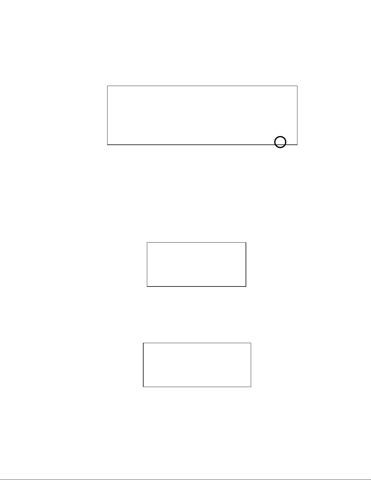
OUTPUT CONFIG
●4-20mA CH1
→POWER SEL
INTERNAL
Figure 3 SONARtrac Front Panel Menu Power Select Setting Internal and
OUTPUT CONFIG
●4-20mA CH1
→POWER SEL
EXTERNAL
External
Copyright © 2007 CiDRA Corporation Page 4-1
20984-01 Rev 01
Page 22
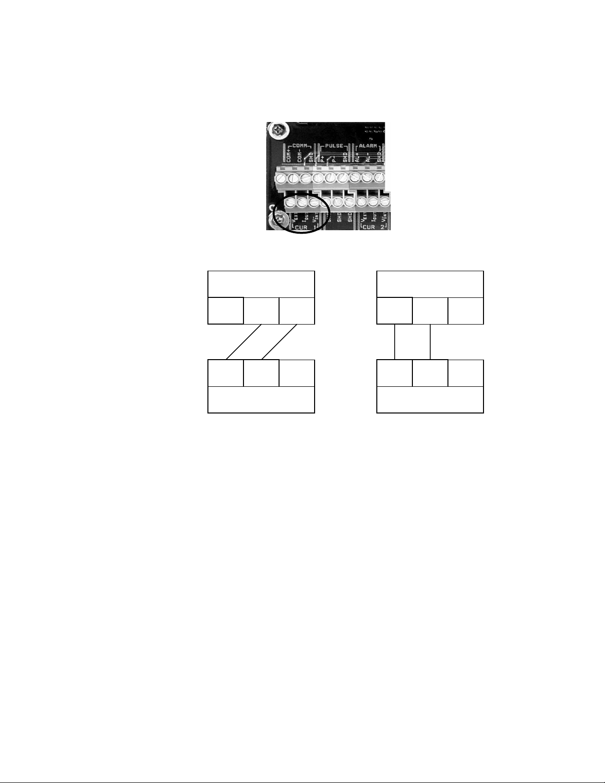
4.2.2 4-20mA Transmitter and DCS Connections
Connect to the appropriate terminals on the transmitter connector
board.
Figure 4 Transmitter Connector Board 4-20mA Conne ctions
SONARtrac transmitter SONARtrac transmitter
(Internal 4-20mA) (External 4-20mA)
V
Plant DCS
Figure 5 Transmitter to DCS Wiring for Internal a nd External Power Select
EXT
I
- +
OUT
V
INT
V
+ -
Plant DCS
EXT
I
OUT
V
INT
4.2.3 Fisher-Rosemount Model 275 Handheld HART Terminal
The polarity is unimportant for the Model 275; however, the
SONARtrac power select MUST be Internal. The value of R must be
250 ohms.
SONARtrac
Transmitter
HART 275
Communicator
Figure 6 SONARtrac Transmitter and HART 275 Communicator
Copyright © 2007 CiDRA Corporation Page 4-2
20984-01 Rev 01
Page 23
4.2.4 HART Activity Indicator
When the SONARtrac receives a valid HART message, an indicator
will appear on the lower right of the SONARtrac display. This indicator
will be removed if another message is not received in 10 seconds.
V
F
T
O
T
SONARTRAC VF H/
235 gal/min
19345 gal
Figure 7 Transmitter Indicator of HART Activity
4.2.5 Transmitter Front Panel Menu Inputs
The following HART options are available from the transmitter front
panel.
4.2.5.1 Universal Command Revision
The most generally deployed HART Revision is 5, the SONARtrac
default HART Protocol Revision. In the case where the SONARtrac
transmitter must communicate with a Revision 6 HART Master, this
option may be changed to 6.
Figure 8 HART Universal Command Revision
4.2.5.2 Polling Address
When using a Point to Point topology, leave the Polling Address at 0.
If using Multi-Drop, set the Polling Address to a number unique from
any other HART devices on the Multi-Drop loop.
Figure 9 HART Polling Address
Copyright © 2007 CiDRA Corporation Page 4-3
20984-01 Rev 01
Page 24
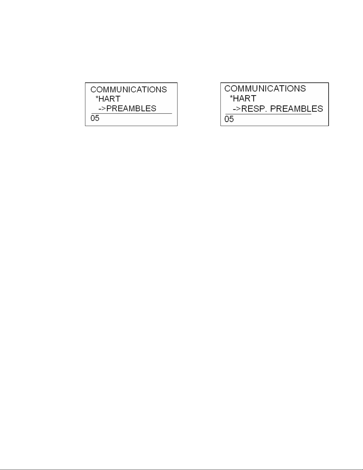
4.2.5.3 Preambles/Response Preambles
The number of Preambles or Response Preambles should not need to
be changed unless the 4-20mA current loop is noisy. The maximum
preambles setting is 20.
Figure 10 HART Preambles and Response Preambles
4.2.6 Transmitter Configuration File HART Settings
In addition to the transmitter front panel inputs, the following inputs
can be made through one of the SONARtrac Utility Programs.
4.2.6.1 Description
Any string of 16 valid HART characters. This is used to describe the
transmitter application, tag number, or any other information the
customer may wish.
4.2.6.2 Date
Date field readable by the attached HART master. This can be used
to save an installation date for example.
4.2.6.3 Tag
Any string of 8 valid HART characters. This string will appear on the
display of the Model 275 HART communicator.
4.2.6.4 Long Tag
Any string of 40 valid HART characters. Used in HART Universal
Command Rev 6 as a HART identifier.
4.2.6.5 Message
Any string of 32 HART characters. This string is shown on the lower
left of the SONARtrac display, and may be used to identify the
installation.
4.2.6.6 Device Serial Number
3 digit serial number of the transmitter.
4.2.6.7 Final Assembly
Three (3) digit final assembly number of the transmitter.
4.2.6.8 Damping
Currently not used.
Copyright © 2007 CiDRA Corporation Page 4-4
20984-01 Rev 01
Page 25

4.2.6.9 PV Trim
Value subtracted from the HART ‘Primary Variable’ (i.e. VF).
4.3 HART Troubleshooting
4.3.1 HART Master Does Not Connect to SONARtrac
4.3.1.1 The HART Activity Icon Does NOT Appear on Display
• Check the Internal/External POWER SEL setting for 4-20mA CH 1.
• Check that the Universal Command Rev matches the master.
• Check the polling address – 0 if Point to Point, unique if multi-drop.
4.3.1.2 The HART Activity Icon DOES Appear on Display
• Check that the Universal Command Rev matches the master.
• Check the polling address – 0 if Point to Point, unique if multi-drop.
4.3.2 Primary Value Read Using HART Does Not Match SONARtrac
• Check that the PV Trim value is 0.
4.3.3 Connection to SONARtrac Is Intermittent
• Increase the PREAMBLES or RESP. PREAMBLES on SONARtrac
transmitter.
Copyright © 2007 CiDRA Corporation Page 4-5
20984-01 Rev 01
Page 26

4.4 HART Commands
The following is a list of supported HART commands.
Command Name HART 5 or 6
Universal Commands
0 Read unique identifier
1 Read primary variable
2 Read current and percent of range
3 Read current and four (predefined) dynamic variables
4 Reserved
5 Reserved
6 Write polling address
7 Read loop configuration HART 6
8 Read dynamic variable families HART 6
9 Read Device Variables with Status HART 6
11 Read unique identifier associated with tag
12 Read message
13 Read tag, descriptor, date
14 Read PV sensor information
15 Read output information
16 Read final assembly number
17 Write message
18 Write tag, descriptor, date
19 Write final assembly number
20 Read long tag HART 6
21 Read unique ID associated with long tag HART 6
22 Write long tag HART 6
Common Practice Commands
33 Read transmitter variables
34 Write damping value
35 Write range values
36 Set upper range value (= push SPAN button)
37 Set lower range value (= push ZERO button)
38 Reset "configuration changed" flag
39 EEPROM control
40 Enter/exit fixed current mode
41 Perform device self- test
42 Perform master reset
43 Set (trim) PV zero
44 Write PV units
45 Trim DAC zero
46 Trim DAC gain
47 Write transfer function
48 Read additional device status
49 Write PV sensor serial number
HART 5 & 6 YES
HART 5 & 6 YES
HART 5 & 6 YES
HART 5 & 6 YES
HART 5 & 6 YES
HART 5 & 6 YES
HART 5 & 6 YES
HART 5 & 6 YES
HART 5 & 6 YES
HART 5 & 6 YES
HART 5 & 6 YES
HART 5 & 6 YES
HART 5 & 6 YES
HART 5 & 6 YES
HART 5 & 6 YES
HART 5 & 6 YES
HART 5 & 6 YES
HART 5 & 6 YES
HART 5 & 6 YES
HART 5 & 6 YES
HART 5 & 6 YES
HART 5 & 6 YES
HART 5 & 6
HART 5 & 6 YES
HART 5 & 6 YES
HART 5 & 6 YES
HART 5 & 6 YES
HART 5 & 6 YES
HART 5 & 6 YES
HART 5 & 6 YES
HART 5 & 6 YES
HART 5 & 6 YES
HART 5 & 6 YES
Supported
by CiDRA
YES
YES
YES
YES
YES
YES
NO
Copyright © 2007 CiDRA Corporation Page 4-6
20984-01 Rev 01
Page 27

50 Read dynamic variable assignments (4.1)
51 Write dynamic variable assignments (4.1)
52 Set transmitter variable zero (4.1)
53 Write transmitter variable units (4.1)
54 Read transmitter variable information (4.1)
55 Write transmitter variable damping value (4.1)
56 Write transmitter variable sensor serial number (4.1)
57 Read unit tag, descriptor, date (5.0)
58 Write unit tag, descriptor, date (5.0)
59 Write number of response preambles (5.0)
60 Read analogue output and percent of range (5.1)
61 Read dynamic variables and PV analogue output (5.1)
62 Read analogue outputs (5.1)
63 Read analogue output information (5.1)
64 Write analogue output additional damping value (5.1)
65 Write analogue output range values (5.1)
66 Enter/exit fixed analogue output mode (5.1)
67 Trim analogue output zero (5.1)
68 Trim analogue output gain (5.1)
69 Write analogue output transfer function (5.1)
70 Read analogue output endpoint values (5.1)
71 Lock device HART 6 NO
72 Squawk HART 6
73 Find device HART 6
74 Read I/O system capabilities HART 6 NO
75 Poll sub-device HART 6 NO
76 Read Lock Device State HART 6 YES
79 Write device variable HART 6 NO
80 Read device variable trim points HART 6 NO
81 Read device variable trim guidelines HART 6 NO
82 Write device variable trim point HART 6 NO
83 Reset device variable trim HART 6 NO
105 Read Burst Mode Configuration HART 6 NO
106 Flush delayed responses HART 6 NO
107 Write burst mode transmitter variables (for Command #33) (5.1)
108 Write burst mode command number (5.0)
109 Burst mode control (5.0)
110 Read all dynamic variables (5.0)
111 Transfer service control HART 6 NO
112 Transfer service HART 6 NO
113 Catch device variable HART 6 NO
114 Read caught device variable HART 6 NO
141 Clear Existing Alarm Condition (see Note 1)
Note 1: CiDRA specific command
HART 5 & 6
HART 5 & 6
HART 5 & 6
HART 5 & 6
HART 5 & 6
HART 5 & 6
HART 5 & 6
HART 5 & 6
HART 5 & 6
HART 5 & 6
HART 5 & 6
HART 5 & 6
HART 5 & 6
HART 5 & 6
HART 5 & 6
HART 5 & 6
HART 5 & 6
HART 5 & 6
HART 5 & 6
HART 5 & 6
HART 5 & 6
HART 5 & 6
HART 5 & 6
HART 5 & 6
HART 5 & 6
HART 5 & 6
NO
NO
NO
YES
NO
NO
NO
NO
NO
YES
NO
NO
NO
NO
NO
NO
NO
NO
NO
NO
NO
YES
YES
NO
NO
NO
NO
YES
Copyright © 2007 CiDRA Corporation Page 4-7
20984-01 Rev 01
Page 28

*** This Page is Blank ***
Copyright © 2007 CiDRA Corporation Page 4-8
20984-01 Rev 01
Page 29

Page 30

CiDRA Corporation
50 Barnes Park North
Wallingford, CT 06492
(In U.S.): 877-cidra77
Tel: 203-265-0035
Fax: 203-294-4211
Visit CiDRA Online at: www.cidra.com
CiDRA Corporation 50 Barnes Park North Wallingford, CT 06492
Tel. 203-265-0035 Fax. 203-294-4211 www.cidra.com
 Loading...