

CiDRA GVF-100 User Manual

MODEL VF & GVF-100 FLOW and
ENTRAINED GAS MONITORING
SYSTEM
INSTALLATION & STARTUP
MANUAL
CiDRA Corporation 50 Barnes Park North Wallingford, CT 06492
Tel. 203-265-0035 Fax. 203-294-4211 www.cidra.com


Table of Contents
1 INTRODUCTION.................................................................................1-1
1.1 Sensor Head Description and Function..............................................1-1
1.2 Transmitter Description and Function ................................................1-1
2 INTELLECTUAL PROPERTY NOTICES.............................................2-1
3 EQUIPMENT SAFETY COMPLIANCE ...............................................3-1
3.1 Safety.................................................................................................3-1
3.2 North American Emissions.................................................................3-1
3.3 European Emissions and Immunity....................................................3-1
3.4 CE Marking.........................................................................................3-2
4 WARRANTY........................................................................................4-1
5 GENERAL SAFETY GUIDELINES......................................................5-1
5.1 Introduction.........................................................................................5-1
5.2 Safety Precautions.............................................................................5-1
5.3 Definitions of Symbols........................................................................5-1
5.3.1 General Warning or Caution.........................................................5-2
5.3.2 Grounding.....................................................................................5-2
5.3.3 On.................................................................................................5-2
5.3.4 Off.................................................................................................5-2
5.3.5 General Warnings ........................................................................5-3
5.3.6 General Cautions .........................................................................5-4
6 UNPACKING AND PARTS LIST.........................................................6-1
6.1 Unpacking ..........................................................................................6-1
6.2 Inventory of Parts...............................................................................6-1
6.3 Class I, Division 2 Labels...................................................................6-2
7 SENSOR INSTALLATION...................................................................7-1
7.1 Class I, Division 2, Groups A, B, C, and D Rated Equipment ............7-1
7.2 Tools Required For Installation .......................................................... 7-1
7.3 Sensor Installation Guidelines............................................................7-2
7.4 Process Piping Considerations ..........................................................7-2
7.4.1 Pipe Preparation...........................................................................7-2
7.4.2 Determine the Pipe Inner Diameter (ID).......................................7-3
7.5 Sensor Band Installation ....................................................................7-4
7.5.1 Sensor Band Short Test...............................................................7-8
7.6 Sensor Cover Installation...................................................................7-9
7.6.1 Fiberglass Cover Installation......................................................7-10
7.6.2 Stainless Steel Cover Installation...............................................7-13
7.6.3 Sensor Assembly Cable Connection..........................................7-17
7.6.4 Rain Boot Installation .................................................................7-18
7.6.5 Sensor Calibration Label............................................................7-18
7.7 Sensor to Transmitter Cable Connections .......................................7-20
7.7.1 Sensor End Cable Attachment...................................................7-20
7.8 Installations on Tubing .....................................................................7-21
8 TRANSMITTER INSTALLATION.........................................................8-1
8.1 Transmitter Power Requirements.......................................................8-1
8.2 Transmitter Environmental Conditions ...............................................8-1
8.3 Transmitter Mounting Instructions......................................................8-1
8.3.1 Bulkhead Mounting.......................................................................8-2
8.3.2 Pipe Mounting ..............................................................................8-2
8.4 Transmitter Cable Connections..........................................................8-3
Copyright © 2006 CiDRA Corporation Page i
20675-01 Rev 02

8.4.1 Transmitter Housing Cable Entry.................................................8-3
8.4.2 Transmitter Output, Sensor and Sensor Head Connections........8-4
8.4.3 Transmitter Electrical Power Cable Installation..........................8-10
8.4.4 Sensor Calibration Label............................................................8-12
9 TRANSMITTER FUNCTIONS.............................................................9-1
9.1 Transmitter Layout .............................................................................9-1
9.2 Transmitter Output Definitions............................................................9-2
9.3 Transmitter Input Definitions ..............................................................9-6
9.4 Keypad...............................................................................................9-7
9.5 Transmitter Display ............................................................................9-8
9.5.1 Operational Mode.........................................................................9-8
9.5.2 Menu Mode ................................................................................9-12
10 TRANSMITTER SETUP....................................................................10-1
10.1 Transmitter Menus ...........................................................................10-1
10.1.1 Basic Config Menu .....................................................................10-1
10.1.2 Output Config Menu ...................................................................10-3
10.1.3 Input Config..............................................................................10-13
10.1.4 Customize Menu ......................................................................10-13
10.1.5 Communications Menu.............................................................10-15
10.1.6 Diagnostics Menu.....................................................................10-15
10.1.7 Info Menu .................................................................................10-17
10.2 Resetting Processor.......................................................................10-18
10.3 Resetting to Factory Defaults.........................................................10-19
11 TRANSMITTER STARTUP & OPERATION......................................11-1
11.1 Initial Start-up...................................................................................11-1
11.1.1 Initial Setup.................................................................................11-1
12 TRANSMITTER USB PORT ..............................................................12-1
12.1 USB Port File Naming Convention...................................................12-3
12.2 Save Snapshot.................................................................................12-4
12.3 Load Configuration...........................................................................12-4
12.4 Advanced Functions.........................................................................12-5
13 SENSOR REMOVAL PROCEDURE.................................................13-1
Appendix A SONARtrac
Appendix B SONARtrac
Appendix C
INCENDIVE........................................................................................C-1
Appendix D
Appendix E
Appendix F
Appendix G
Appendix H
Appendix I
SYSTEM CONTROL DRAWING SONARtracTM, NON-
MATERIAL SAFETY DATA SHEETS......................................D-1
CONVERSION FACTORS ...................................................... E-1
PHYSICAL PROPERTIES OF WATER....................................F-1
END USER LICENSE AGREEMENT......................................G-1
SPARE PARTS LIST............................................................... H-1
DIRECTIVE 2002/96/EC ON WASTE ELECTRICAL AND
ELECTRONIC EQUIPMENT (WEEE)..................................................I-1
TM
VF & GVF-100 SPECIFICATIONS................... A-1
TM
EC DECLARATION OF CONFORMITY........... B-1
Copyright © 2006 CiDRA Corporation Page ii
20675-01 Rev 02

List of Figures
Figure 1 General Warning or Caution Symbol..........................................5-2
Figure 2 Grounding Symbol......................................................................5-2
Figure 3 On Symbol..................................................................................5-2
Figure 4 Off Symbol..................................................................................5-2
Figure 5 Class I Division 2 Label Information............................................6-2
Figure 6 Sensor Band Screw and Alignment Pins....................................7-4
Figure 7 Sensor Band Screw Tightening Sequence.................................7-5
Figure 8 Sensor Band Screw Assembly....................................................7-6
Figure 9 Sensor Band Spacer Tool........................................................... 7-6
Figure 10 Sensor Band Spacing Tool Installed on Sensor Screw ..............7-7
Figure 11 Installed Sensor Band.................................................................7-8
Figure 12 Upper Sensor Cover Assembly Outside View ............................7-9
Figure 13 Upper Sensor Cover Assembly Inside View...............................7-9
Figure 14 Orientation (Clocking) of Sensor Cover....................................7-10
Figure 15 Sensor Cover Bolt Installation...................................................7-11
Figure 16 Sensor Cover Bolt Tightening Sequence..................................7-12
Figure 17 Stainless Steel Cover Assembly...............................................7-13
Figure 18 Applying GelTek to Gasket Edge..............................................7-14
Figure 19 Boot Gasket Band Kit................................................................7-14
Figure 20 Boot Gasket Band Installation...................................................7-14
Figure 21 Splice Protector Plate Installation.............................................7-15
Figure 22 BAND-IT
Figure 23 Final Alignment and Securing of Gasket Band.........................7-16
Figure 24 Band Termination......................................................................7-16
Figure 25 Boot Gasket Fender Assembly.................................................7-17
Figure 26 Sensor Assembly Cable Installation .........................................7-17
Figure 27 Sensor Calibration Label...........................................................7-19
Figure 28 Elastomeric Strip Installation on Tubes.....................................7-21
Figure 29 Bulkhead Mount Hole Pattern.....................................................8-2
Figure 30 Pole Mount Kit.............................................................................8-2
Figure 31 Power and Signal Interconnects.................................................8-3
Figure 32 Transmitter Housing Cable Gland Holes ....................................8-3
Figure 33 Terminal Board Layout................................................................8-4
Figure 34 Transmitter Output Terminals.....................................................8-5
Figure 35 Transmitter Sensor Terminals.....................................................8-6
Figure 36 Sensor Head to Transmitter Cable Connection Terminals .........8-7
Figure 37 Armored Cable Stiffener Plate Installation..................................8-8
Figure 38 Removal of Cable Armor.............................................................8-9
Figure 39 Armored Cable Connector Installed............................................8-9
Figure 40 Armored Cable Installation........................................................8-10
Figure 41 Transmitter Power Connection .................................................8-11
Figure 42 Sensor Calibration Label...........................................................8-12
Figure 43 Transmitter Layout......................................................................9-1
Figure 44 Transmitter Output Terminals.....................................................9-2
Figure 45 Pulse Switch Closure..................................................................9-3
Figure 46 Alarm Switch Closure..................................................................9-3
Figure 47 Internally (Transmitter) Powered 4–20mA Loop.........................9-4
Figure 48 Externally Powered 4–20mA Loop..............................................9-5
Figure 49 Transmitter Sensor Terminals.....................................................9-6
®
Model C001 Tool Use..............................................7-15
Copyright © 2006 CiDRA Corporation Page iii
20675-01 Rev 02

Figure 50 Transmitter Front Panel Keyboard..............................................9-7
Figure 51 VF & GVF Startup Screen...........................................................9-8
Figure 52 Operating Transmitter Display....................................................9-9
Figure 53 Initialization Mode.....................................................................9-12
Figure 54 GVF Measurement Screen.......................................................9-12
Figure 55 Typical Menu Screen................................................................9-14
Figure 56 Editing Parameter By Digits......................................................9-14
Figure 57 Editing Whole Parameter..........................................................9-15
Figure 58 Low End Output Configuration Example Screen ......................10-4
Figure 59 High End Output Configuration Example Screen......................10-4
Figure 60 4-20mA Output Set to 0 – 30 fps ..............................................10-5
Figure 61 4-20mA Trim Message box.......................................................10-6
Figure 62 Speed Of Sound and Gas Volume Fraction Pulse Output........10-8
Figure 63 Total Flow Pulse Output............................................................10-8
Figure 64 Test Passes Display Example ................................................10-15
Figure 65 Test Failed..............................................................................10-15
Figure 66 Error Codes Listed in Event Log.............................................10-18
Figure 67 Sensor Max/Min Display.........................................................10-18
Figure 68 System Start Display.................................................................11-1
Figure 69 Sensor Cable Connector Removal ...........................................13-1
List of Tables
Table 1 SONARtracTM VF & GVF-100 Parts List......................................6-1
Table 2 Installation Tools For SONARtrac
TM
VF & GVF-100 Monitoring
System........................................................................................7-1
Table 3 Recommended Distances From Flow Disturbances....................7-2
Table 4 Gauge Block and Screw Size......................................................7-5
Table 5 List of Transmitter Signal Outputs...............................................8-5
Table 6 Sensor to Transmitter Cable Terminal Connections....................8-8
Table 7 Keypad Functions in Operational and Menu Modes....................9-7
Table 8 Line 1 and Line 2 Values.............................................................9-9
Table 9 Status Line Code.........................................................................9-9
Table 10 Status Line Messages...............................................................9-10
Table 11 Quality Message Definitions .....................................................9-10
Table 12 Mode Message Definitions........................................................9-11
Table 13 SONARtrac
TM
VF & GVF-100 Menu Diagram Software Release
03.03.XX...................................................................................9-13
Table 14 Transmitter Menu Tree Software Release 03.03.XX................9-16
Table 15 Maximum Pulse Per Second Based On Pulse Width ...............10-7
Table 16 Alarm Triggers ........................................................................10-10
Table 17 Transmitter Setup .....................................................................11-7
Table 18 USB Port Menu.........................................................................12-2
Table 19 USB Port File Naming Convention............................................12-3
Table 20 USB Port File Name Examples.................................................12-3
Copyright © 2006 CiDRA Corporation Page iv
20675-01 Rev 02

1 INTRODUCTION
The CIDRA Corporation SONARtracTM Model VF & GVF-100
(Volumetric Flow and Gas Volume Fraction) System is a clamp-on
process monitoring system used to measure the volumetric flow rate
and the amount of entrained air / gas (also referred to as gas volume
fraction or GVF) contained in a fluid within process pipes on a realtime basis. The SONARtracTM VF & GVF-100 utilizes patented array
processing techniques to listen to and interpret the flow turbulence
generated by fluid flow and the acoustic field generated by machinery,
piping and flow present in process flow. The clamp-on design
eliminates the need for cutting pipe or interrupting process flow during
installation.
The SONARtracTM VF & GVF-100 consists of a common transmitter
and sensor heads sized for different pipe diameters.
SONARtracTM flow and entrained gas meters certified for use in
hazardous areas are rated for use in Class I, Division 2, Groups A, B,
C, and D environments (per US and Canadian standards).
This manual covers the basic installation and setup of the
SONARtracTM Model VF & GVF-100 Monitoring System. In all cases,
local safety and operating practices take precedence over the
information contained within this document.
For additional information, contact your local sales agent or CiDRA
Corporation Customer Support by telephone at 1-877-243-7277
(1-877-CIDRA77) or by E-Mail at customersupport@cidra.com
1.1 Sensor Head Description and Function
The SONARtracTM sensor head contains no moving parts. The sensor
head includes a sensor band and a fiberglass or stainless steel cover
assembly to protect the sensor band. The sensor band is wrapped
around and clamped onto the process pipe. A multi-conductor cable
electrically connects the sensors to an electronic module mounted in
the cover assembly. Signals from the electronic module exit through a
NEMA 4X rated connector mounted to the outer surface of the cover
assembly.
1.2 Transmitter Description and Function
The SONARtracTM transmitter receives electrical signals from the
sensor head. The signals are processed using SONARtrac
processing firmware that displays the calculated results on an integral
LCD screen. Results can also be transmitted using the 4–20mA
analog output, pulse output, alarm output or the RS-485/232 digital
TM
array
Copyright © 2006 CiDRA Corporation Page 1-1
20675-01 Rev 02

output. The electronic assembly is housed in a rugged NEMA 4X
enclosure.
Copyright © 2006 CiDRA Corporation Page 1-2
20675-01 Rev 02

2 INTELLECTUAL PROPERTY NOTICES
CiDRA Corporation’s Process Monitoring Products may be covered by
one or more of the following granted U.S. Patent(s): 6,354,147,
6,587,798, 6,609,069, 6,435,030, 6,691,584, 6,732,575, 6,782,150,
6,862,920, 6,889,562, 6,732,150. Other patents are pending; see
www.cidra.com for the latest listing of patents.
This manual is covered by U.S. and international copyright laws. No
part of this manual may be reproduced, modified or transmitted in
whole or in part in any form or by any means, electronic or
mechanical, including photocopy, recording, or any information
storage and retrieval system, without permission in writing from
CiDRA Corporation.
Third party end-user license agreements (“EULA”) are provided in
Appendix G of this document.
Copyright © 2006 by CiDRA Corporation, all rights reserved.
SONARtrac, SONARstick and logo are trademarks of CiDRA
Corporation.
Copyright © 2006 CiDRA Corporation Page 2-1
20675-01 Rev 02

3 EQUIPMENT SAFETY COMPLIANCE
3.1 Safety
This equipment is listed with TÜV Rheinland of North America, Inc., a
nationally recognized testing laboratory, and certified for ordinary
location use per the following US, Canadian, and European standards:
UL 61010A-1, CSA C22.2 No. 1010, and EN 61010-1:2001.
If so marked, this equipment is certified by Underwriters Laboratories
for use in areas that - under fault conditions - include explosive gas
atmospheres as defined by Class I, Division 2, Groups A, B, C, and D
per compliance with these US and Canadian standards: UL 1604, UL
508, CSA C22.2 No. 213, and CSA C22.2 No. 142.
3.2 North American Emissions
This equipment is compliant with Class A limits for radiated and
conducted radio noise emissions, as defined in Subpart A of Part 15 of
the FCC rules, as well as the requirements defined in ICES-003 for
Canada.
This Class A digital apparatus complies with Canadian ICES-003.
Cet appareil numérique de la classe A est conforme à la norme NMB-
003 du Canada.
3.3 European Emissions and Immunity
This equipment is compliant with the requirements set forth in EN
61326-1:1997, Electrical Equipment for Measurement, Control and
Laboratory Use - EMC requirements as well as EN 55011:1998
Industrial, Scientific, and Medical (ISM) Radio Frequency Equipment Radio Disturbance Characteristics - Limits and Methods of
Measurement.
For the purpose of Electromagnetic Compatibility (EMC) requirements,
this product is categorized as Group 1, Class A ISM equipment. This
categorization applies to Industrial, Scientific or Medical equipment
that intentionally generates or uses conductively coupled (but not
intentionally radiated) radio-frequency energy that is necessary for the
internal functioning of the equipment. The level of EMC compliance is
consistent with industrial use but not for domestic purposes.
CAUTION
Class A equipment is intended for use in an industrial
environment. There may be potential difficulties in ensuring
electromagnetic compatibility in other environments, due to
conducted as well as radiated disturbances.
Copyright © 2006 CiDRA Corporation Page 3-1
20675-01 Rev 02

3.4 CE Marking
This equipment is CE marked for ordinary location use and complies
with the following European Directives:
73/23/EEC Low-Voltage Directive
89/336/EEC EMC Directive
Further details are listed in the EC Declaration of Conformity (P/N
20634-01), a copy of which can be found in Appendix B of this
Document as well as on our website at http://www.cidra.com.
Copyright © 2006 CiDRA Corporation Page 3-2
20675-01 Rev 02

4 WARRANTY
The terms and conditions, including warranty, of the purchase of
CiDRA’s Process Monitoring Products is outlined in the document
entitled “CiDRA’s Terms and Conditions of Sale”.
Copyright © 2006 CiDRA Corporation Page 4-1
20675-01 Rev 02

5 GENERAL SAFETY GUIDELINES
CiDRA Corporation recommends the installer fully read this manual
prior to installing and operating the SONARtrac
Note: Items that pertain to systems rated for Class I, Division 2,
Groups A, B, C, and D operation are highlighted in italic print.
5.1 Introduction
This manual is intended to be a general installation guide for the
CiDRA SONARtracTM VF & GVF-100 System. It is not intended to
cover the installation details for every process due to the wide variety
of applications and processes on which the system can be used. In all
cases, local safety and operating practices should take precedence
over instructions contained within this manual.
5.2 Safety Precautions
The following style of Warnings and Cautions are used throughout the
manual to draw attention to information regarding personnel safety
and equipment care. They are not intended to replace local or plant
safety procedures.
WARNING
TM
system.
Situation has the potential to cause bodily harm or death.
Situation has the potential to cause damage to property or
equipment.
5.3 Definitions of Symbols
The following terms and symbols are used in this document and on
the SONARtracTM system where safety related issues occur.
CAUTION
Copyright © 2006 CiDRA Corporation Page 5-1
20675-01 Rev 02
5.3.1 General Warning or Caution
Figure 1 General Warning or Caution Symbol
The Exclamation Symbol in Figure 1 appears in Warning and Caution
tables throughout this document. This symbol designates an area
where personal injury or damage to the equipment is possible.
5.3.2 Grounding
Figure 2 Grounding Symbol
The Grounding Symbol in Figure 2 appears on labels affixed to the
SONARtracTM system. This symbol identifies a terminal intended for
connection to an external (ground) conductor for protection against
electric shock in case of a fault, or the terminal of a protective earth
(ground) electrode.
5.3.3 On
The On Symbol in Figure 3 represents the Power ON condition of the
power switch on the SONARtrac
• Class I, Division 2 rated systems do not have this switch.
5.3.4 Off
Figure 3 On Symbol
TM
system, if so equipped.
Figure 4 Off Symbol
The Off Symbol in Figure 4 represents the Power Off condition of the
TM
power switch on the SONARtrac
system, if so equipped.
• Class I, Division 2 rated systems do not have this switch.
Copyright © 2006 CiDRA Corporation Page 5-2
20675-01 Rev 02
5.3.5 General Warnings
Observe these general warnings when operating or servicing this
equipment:
• Prior to operation of this equipment, personnel should read the
instruction manual thoroughly.
• For systems installed in Class I, Division 2 areas, Power Entry and
Inputs/Outputs must be installed in accordance with Article
501.10(B)(1) of the National Electrical Code ANSI/NFPA 70:2005.
• For systems installed in Class I, Division 2 areas, Sensor Head
Cable must be installed in accordance with Article 501.10(B)(3) of
the National Electrical Code ANSI/NFPA 70:2005.
• Only equipment rated for Class I, Division 2, Groups A, B, C, and
D should be installed in those areas. Verify the system rating on
the equipment labels (refer to Section 6.3 of this manual).
• Use a damp cloth to wipe sensor band cover and transmitter when
installed in Class I, Division 2 areas to dissipate potential static
charge buildup.
WARNING
Using a dry cloth to clean the transmitter enclosure can cause
static discharge, which could result in an explosion in an
explosive atmosphere. Always use a damp cloth to clean the
transmitter enclosure.
• If the sensor band was shipped with a sensor band shorting plug
installed on the sensor band to preamplifier cable connector,
ensure the sensor band shorting plug is installed on the sensor
band cable prior to installing sensor band. Sensors bands with an
‘R” in the Part Number suffix (e.g. Part #: 20686-26-R) do not
require a shorting plug.
• As for any electrical equipment in Class I, Division 2 installations
wherein explosive atmospheres might be present, it is especially
important to de-power and remove the SONARtracTM meter from
service if its appearance or operating behavior indicates that it is
damaged or malfunctioning and/or that its safety features have
been otherwise compromised.
• Trained personnel must carry out service on this equipment.
• Follow all warnings on the unit and in the operating instructions.
• This equipment is grounded through the grounding conductor of
the power cord.
Copyright © 2006 CiDRA Corporation Page 5-3
20675-01 Rev 02

• Ensure all power cords, sensor to transmitter cable and signal
cables are properly routed to eliminate damage to them. Cable
conduit may be desirable to minimize potential damage.
• Prior to servicing, lockout all electrical power sources.
• Care should be taken when using the operator keypad to avoid
touching any electrical connection or contact points.
• Do not wear rings or wristwatches when servicing this equipment.
• Use only the specified fuse(s) with the correct type number,
voltage and current ratings as referenced in the appropriate
locations in the service instructions or on the equipment.
5.3.6 General Cautions
Observe these cautions when operating or servicing this equipment:
• Read the instructions for proper input voltage range selection.
• There are no user serviceable parts inside the SONARtrac
sensor band. Modification or disassembly may void the system
warranty.
TM
• Disconnect power to transmitter prior to replacing fuse(s).
• Use only CiDRA specified replacement parts.
• Follow static sensitive device precautions when servicing.
• This product should only be powered as described in the manual.
• Do not run power and signal wires in a common conduit.
Copyright © 2006 CiDRA Corporation Page 5-4
20675-01 Rev 02
6 UNPACKING AND PARTS LIST
6.1 Unpacking
The SONARtracTM VF & GVF-100 will typically be packaged in three
shipping containers. One box will contain the sensor band and sensor
cover assemblies, and installation hardware; the second box will
contain the transmitter assembly and installation hardware; and the
third box will contain the sensor to transmitter cable assembly.
Note: Cidra Corp. recommends the original packing materials be
saved in the event that the system is removed or relocated.
CAUTION
Use care in unpacking and transporting system. Improper
handling may result in damage to system components.
Whenever possible use the original packing materials to transport the
system to the installation site to minimize the likelihood of damage.
WARNING
Static discharge may occur when handling sensor band and
packing material. Remove from packing materials when entering
hazardous areas. Always keep the sensor band shorting plug
installed until sensor band is installed on the process pipe.
6.2 Inventory of Parts
Table 1 lists the parts contained in the shipping containers.
Description
SONARtracTM VF & GVF-100 Gas Volume Fraction Process Monitoring
System
Sensor Head Cable
Installation Hardware
Sealant, Joint and Thread, PTFE Paste, 3.5 oz Tube – included with
fiberglass sensor cover assemblies
Gauge, Spring Gap (used for sensor installation) - included with sensor
band assembly
Model VF & GVF-100 Flow and Entrained Air Process Monitoring
System Installation & Startup Manual
Kit, Parts, Pole Mounting (Option)
Sensor Rain Guard Kit for vertical installations (Option)
Table 1 SONARtracTM VF & GVF-100 Parts List
Copyright © 2006 CiDRA Corporation Page 6-1
20675-01 Rev 02
6.3 Class I, Division 2 Labels
Transmitters and sensor covers rated for use in Class I, Division 2
areas are labeled with the following information (or a subset of it) so
they can be identified for use in those areas.
Telemetering Equipment For Use in Hazardous Locations
Class I, Division 2, Groups A, B, C, and D Hazardous Locations
Providing Nonincendive Field Circuits When Connected Per DWG #
20332-01
Figure 5 Class I Division 2 Label Information
WARNING
Use of non- Class I, Division 2 rated equipment in Class I,
Division 2 areas may result in a fire or explosion.
Copyright © 2006 CiDRA Corporation Page 6-2
20675-01 Rev 02

7 SENSOR INSTALLATION
7.1 Class I, Division 2, Groups A, B, C, and D Rated Equipment
• Equipment so marked is suitable for use in Class I, Division 2,
Groups A, B, C, and D or non-hazardous locations only.
• WARNING – EXPLOSION HAZARD – Do not disconnect
equipment unless power has been removed or the area is known
to be non-hazardous.
• WARNING – EXPLOSION HAZARD –Substitution of components
may impair suitability for Class I, Division 2.
• WARNING – EXPLOSION HAZARD –Do not replace fuses unless
power has been switched off or the area is known to be nonhazardous.
• WARNING – EXPLOSION HAZARD –Ensure a sensor band
shorting plug is installed on the sensor band cable connector
during installation and removal from process pipe.
7.2 Tools Required For Installation
The following tools are required for system installation. Additional
tools may be required based on particular installation needs.
Required Tools Recommended Tools
Cable cutter Wire number markers
Wrenches, 1/2 “x 9/16”, combination,
open-end, 2 ea
Wire strippers for 20 gauge wire Open end or combination wrench set
Allen wrench or hex driver, 7/64-inch for
No. 6 socket head cap screw, or 5/32inch for No. 10 socket head cap screw
Spacer tool, sensor fastener (provided
with sensor band)
Screw drivers, Blade, 3/16” and 1/4”,
Phillips medium blade
14” Adjustable wrench (armored cable) Socket wrench set
Sandpaper, cleaning rags, etc as
required for pipe cleaning
BAND-IT® Tool Model C001 (or
equivalent) for use with stainless steel
covers. Refer to
for distributor information.
Table 2 Installation Tools For SONARtrac
www.band-it-idex.com
Portable electric screw driver with 7/64
or 5/32-inch hex driver bit
Spring clamps to hold cover halves in
place temporarily
Cable jacketing removal tool
Hacksaw and or armor cutter (armored
cable cutting)
Volt-ohm meter
Electricians tape
System
TM
VF & GVF-100 Monitoring
Copyright © 2006 CiDRA Corporation Page 7-1
20675-01 Rev 02

7.3 Sensor Installation Guidelines
The following are general installation guidelines and recommendations
for installing a
SONARtrac
TM
sensor.
• Where necessary, get a Hot Work Permit prior to installation of
system.
• Select locations with well-developed flow profiles.
• Avoid installation locations directly after piping configurations that
cause flow jetting.
• Install flow sensor upstream of control valves, “T”s, orifice plates,
and any other severe source of flow disturbance.
• Locate the sensor upstream of pipe taps such as those used for
temperature and pressure sensors.
• Good piping practices are required near flanges. This includes
good alignment of pipes, and properly sized and installed gaskets
that do not disturb the flow profile.
• Contact your local distributor or CiDRA Technical Support if you
have questions.
Table 3 lists the recommended installation distances from flow
disturbances. These recommendations apply to flow measurement
installations.
Feature
Upstream
pipe
diameters
90 Degree Elbow 15 5
Double Elbow in plane 25 5
Double Elbow out of plane 40 5
Diffuser (expansion) 30 5
Reducer 15 5
Control Valve 40 10
Flange 2 2
Table 3 Recommended Distances From Flow Disturbances
7.4 Process Piping Considerations
The SONARtracTM sensor head assembly mounts on the process
pipe. There is no need for breaking any process connections or for
shutting down the process. The sensor head must be installed in a
location that ensures a full pipe during operation.
7.4.1 Pipe Preparation
Downstream
pipe
diameters
Remove pipe insulation if it is present.
Copyright © 2006 CiDRA Corporation Page 7-2
20675-01 Rev 02
WARNING
Asbestos containing insulation materials may be present.
Asbestos fibers have been known to cause health problems. If
unsure of the contents of pipe insulation materials contact the
plant representative for that area.
WARNING
Process Heating Tapes may be present. This may present an
electrical shock hazard. Follow plant Lock-out / Tag-out
requirements.
WARNING
Process pipes may be hot. A burn hazard may exist. Use care
when working with hot pipes.
Clean pipe surface using a scraper, sand paper strips, a water (or
solvent for greasy pipes) rinse and final wipe with a clean rag. The
pipe surface under the sensor band assembly should be clean and
free of rust and rust spots, grit, grease, protruding weld spots and
weld splatter. A good guideline is to clean the pipe as if it were going
to be painted.
Avoid dents as they can create flow disturbances within the pipe.
Select a location that ensures full contact between the sensor and the
pipe.
Painted surfaces are normally satisfactory provided they are smooth
and free of chips over 0.25-inch (6.4 mm) diameter. Ensure a smooth
painted finish by sanding the area where the sensor will be mounted.
Finally, wipe the pipe using a damp cloth rag or paper towel.
7.4.2 Determine the Pipe Inner Diameter (ID)
Record the nominal pipe size based on the pipe size and pipe
schedule, as this will be input into the transmitter.
Alternatively, measure and calculate the pipe ID. Accurately measure
the pipe outside diameter (OD). Use an ultrasonic thickness
measurement gauge to determine the wall thickness (t
of 4 locations equally spaced around the pipe and average the
measurements. Calculate the pipe inner diameter (ID = OD – (2t
(There are several vendors of ultrasonic thickness gauges.)
Note: The accuracy of the pipe inner diameter measurement is critical
for high accuracy flow rate measurements as there is a direct
correlation between this measurement and the reported flow rate.
) at a minimum
w
)).
w
Copyright © 2006 CiDRA Corporation Page 7-3
20675-01 Rev 02
7.5 Sensor Band Installation
It will be helpful to have a second person available to assist with
holding the sensor assembly in position during installation.
Note: Prior to installing the sensor band, remove and save the plastic
bag from the sensor band that contains two sensor calibration factor
labels. These will be used as described later in this manual for input
to the transmitter.
Ensure there is no dirt or other foreign material on the sensor
assembly. Remove dirt or foreign matter using a clean cloth
dampened with water.
If the sensor band was shipped with a sensor band shorting plug
installed on the sensor band to preamplifier cable connector, ensure
the sensor band-shorting plug is installed on the sensor band cable
prior to installing sensor band. Sensors bands with an ‘R” in the Part
Number suffix (e.g. Part #: 20686-26-R) do not require a shorting plug.
Position the
SONARtrac
polyimide film (amber colored) against the pipe surface. If possible,
orient the flow direction arrow on the sensor assembly with the
direction of flow within the pipe.
installation constraints, e.g. access to sensor fasteners, install
opposite to flow direction.
TM
sensor band assembly on the pipe with the
Note: If this is not possible due to
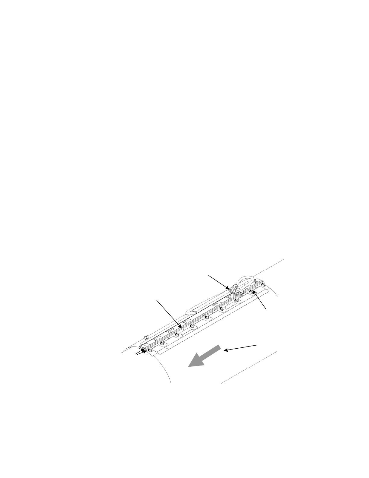
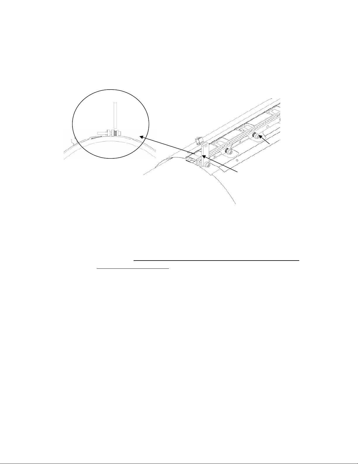
Alignment pins
(typical 2 places)
Attachment rails
Figure 6 Sensor Band Screw and Alignment Pins
Sensor band shorting plug
Sensor attachment screw
assembly (typical 9 places)
Flow direction arrow
Copyright © 2006 CiDRA Corporation Page 7-4
20675-01 Rev 02
Wrap the sensor band around the pipe and slide the alignment pins on
the attachment rail through their mating holes on the opposite
attachment rail. If the process pipe has a welded seam, align the gap
between the sensor attachment rails along the pipe weld seam. Final
positioning can be made after the sensor screws have been started.
Note: When installing the sensor band keep in mind the requirement
for transmitter connector socket assembly orientation as described in
Section 7.6. If necessary, due to cover installation constraints, wrap
the sensor band over the weld seam.
Carefully start threading the screws into their screw holes (avoid cross
threading) by using the hex driver until each screw is engaged about 2
turns. Once all screws are engaged make final positioning of the
sensor assembly with respect to pipe weld seam or desired orientation
on the pipe. The following table provides guidance for selecting the
proper hex tool and spacer gauge.
Sensor Band P/N
20380- ALL SIZES 20143-01 7/64 1/8 x 3/8
20409- ALL SIZES 20143-02 7/64 1/8 x 3/8
20690- ALL SIZES 20143-04 5/32 1/4 x 1/2
20686- ALL SIZES 20143-04 5/32 1/4 x 1/2
Spacer Gauge
P/N
Socket Head Screw
Hex Size (inch)
Table 4 Gauge Block and Screw Size
Band Attachment Rail
Size (Ref)
Start with the center most screw and tighten screws, alternating from
side to side, 3 - 4 turns at a time. Refer to the following figure for the
screw tightening sequence.
Note: Repeat the tightening sequence
only until the Belleville disc springs on the screws begin to compress.
The sensor screw stack up assembly is illustrated in Figure 8.
3 4 5 6 7 8 9
1 2
Sensor band assembly
Figure 7 Sensor Band Screw Tightening Sequence
Copyright © 2006 CiDRA Corporation Page 7-5
20675-01 Rev 02
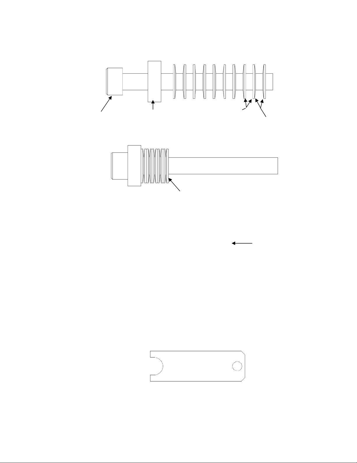
)
Sensor screw
Sensor screw spacer
(may be integral to
screw head
Sensor Belleville washers
concave side
Note: 10 Belleville Washers on 2-16” bands
Sensor Belleville washers
convex side
Belleville washers and spacer
compressed against screw head
Note: Sensor bands 18” and
) ( ) ( ) ( ) ( ) ( ) ( ) (
larger have 14 Belleville washers
per screw arranged as shown
Figure 8 Sensor Band Screw Assembly
Further tightening of the sensor band screws is made while using the
sensor band spacer tool (shown below) furnished with the sensor
band. The spacer tool is used to set the compression on the Belleville
washers referred to above. Refer to Table 4 for the appropriate
spacer tool based on sensor band part number.
Figure 9 Sensor Band Spacer Tool
Copyright © 2006 CiDRA Corporation Page 7-6
20675-01 Rev 02
Using the sensor band screw tightening sequence shown in Figure 9,
insert the sensor band spacer tool over the Belleville washers on the
middle sensor screw assembly and tighten it such that it is snug but
the spacer tool can still be removed. The following figure illustrates
use of the sensor band screw spacer tool.
Side view
Sensor screw with
Belleville washers
compressed (typ)
Sensor screw spacing tool
installed on sensor screw
Figure 10 Sensor Band Spacing Tool Installed on Sensor Screw
Note: Ensure the spacer tool is perpendicular to the attachment rail to
ensure proper tightness. Remove the tool, move to the next sensor
screw, and repeat the tightening on each of the sensor screws.
Important: Tighten each screw once only. Do not retighten each
screw using the gauge.
Final sensor band screw tightening is as follows:
A. For sensor bands sized for 6” and smaller pipe:
1. Tighten screws #1-7 an additional one-half turn in the numbered
sequence given in Figure 7. Do not tighten screw #8 & 9 (screws
on either end of the sensor band).
B. For sensor bands sized for 8” and larger pipe:
1. Starting at screw #1 in Figure 7, tighten each screw an additional
one-half turn in the given numbered sequence.
2. Once all nine screws have been tightened, tighten each screw an
additional one-half turn in the given numbered sequence.
3. Once all nine screws have been tightened a second time, tighten
screws #1-7 an additional one-half turn in the given numbered
sequence.
Attach the sensor cable in the retaining clip on the top of the sensor
band. The connector on this cable will attach to the sensor cover
Copyright © 2006 CiDRA Corporation Page 7-7
20675-01 Rev 02

connector as described later in the manual. If necessary, use a piece
of tape to temporarily retain the connector on the band so it will be
positioned directly below the sensor cable access panel. The final
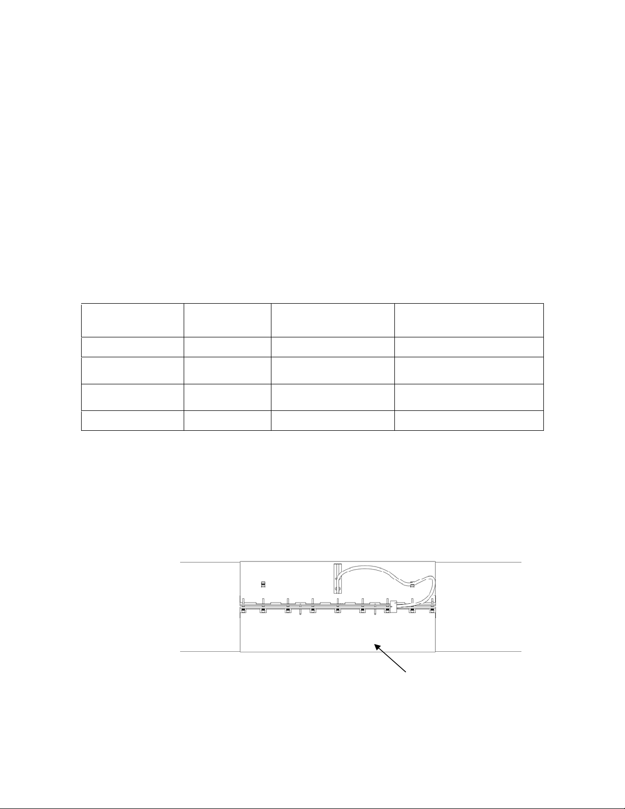
sensor band assembly is illustrated below.
Sensor screws
tightened
Sensor cable installed
in cable retaining clip
Sensor cable connector with
shorting plug installed
Alignment pins
Figure 11 Installed Sensor Band
CAUTION
Over-tightening of fasteners may damage threads on the sensor.
Under tightening may affect flow meter performance. Always
use the sensor fastener spacer tool to ensure proper fit of the
sensor assembly.
7.5.1 Sensor Band Short Test
Shorting of the sensor band to the process pipe may cause signal
interference or electrical faults in the system in some instances. The
sensor band must be electrically isolated from the process pipe.
Use an ohm meter and verify the sensor band is isolated from the
pipe. Measure the resistance between the sensor rails and the pipe to
ensure there is no continuity between the sensor band and the
process pipe. If the band is shorted identify where the short is located
and eliminate the short. For example, if a sensor screw is shorting to
a pipe weld bead, reposition the sensor band, or lightly file the weld
bead to eliminate the interference.
Copyright © 2006 CiDRA Corporation Page 7-8
20675-01 Rev 02
t
r
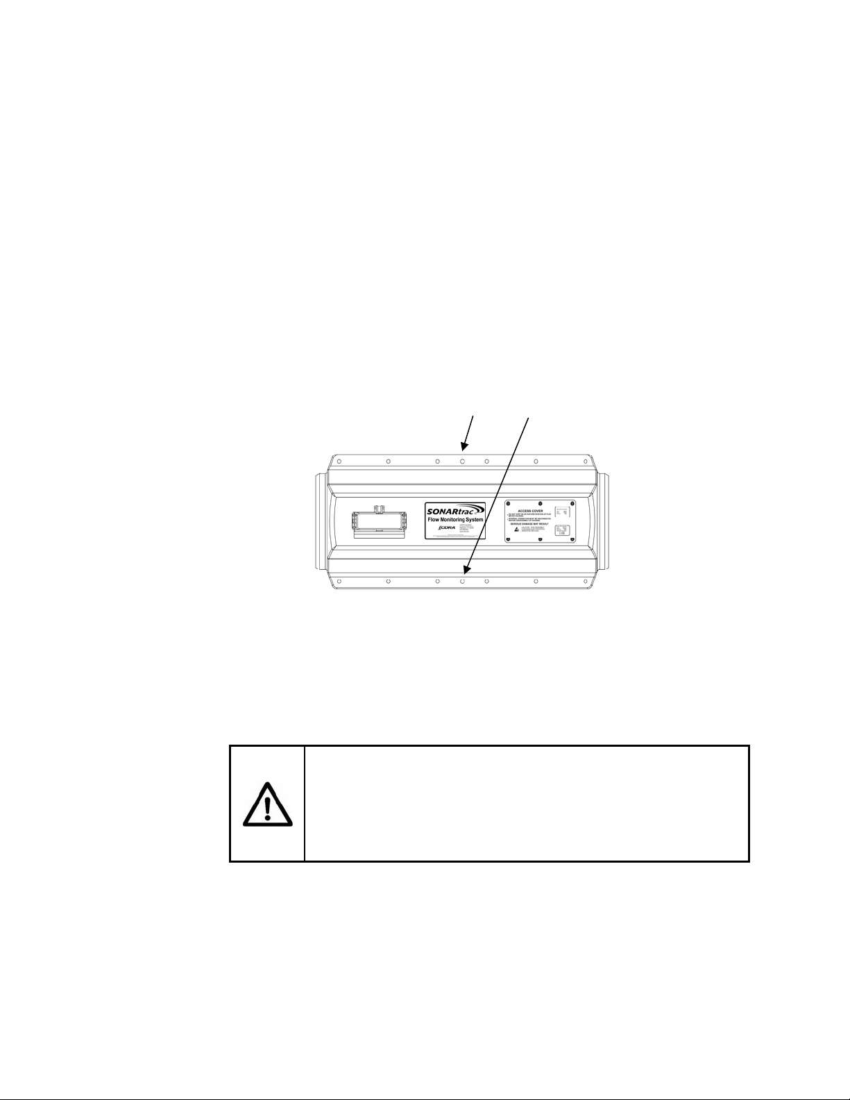
7.6 Sensor Cover Installation
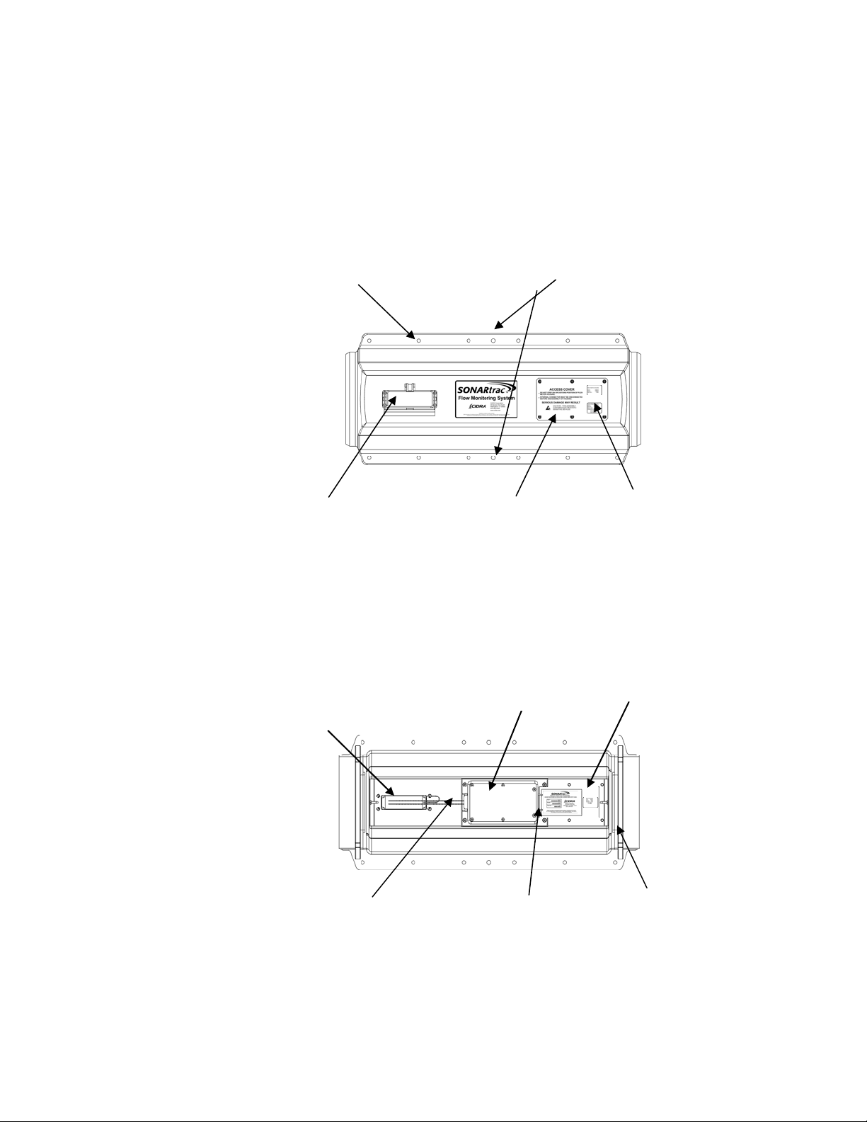
The upper sensor cover assembly outside and inside are illustrated in
the following figures. Cover sizes up to 16 inch are typically made of
fiberglass. Cover sizes 18 inch and above are made from stainless
steel. The layout of both styles is essentially the same. The
differences in installation will be called out in the following sections.
Sensor cover bolt holes (12 places)
Transmitter cable
connector socke
Sensor cable access panel
Figure 12 Upper Sensor Co ver Assembly Outside View
Transmitter cable
connector socket base
Sensor cover alignment bolt holes (2 places)
Pre-amplifier
electronics board and
Pre-amplifier
cove
Sensor band
information label
Sensor cable access panel
Pre-amplifier outlet cable
connector assembly
Sensor band cable socket
Upper cover gasket
Figure 13 Upper Sensor Co ver Assembly Inside View
Copyright © 2006 CiDRA Corporation Page 7-9
20675-01 Rev 02
It is helpful to have a second person available to help when installing
the cover assembly. When the sensor head is installed on a
horizontal pipe, the sensor cover should be installed such that the
transmitter cable connector socket is located within the 105° arcs
shown in the following figure. Do not install the cover with the
transmitter cable connector socket installed downward. (An electrical
pre-amplifier board is mounted on the inside of the cover.) The ability
to route the sensor band to sensor cover cable may dictate cover
orientation. The cable gland on the sensor head to transmitter cable
connector, when installed, should face away from the cover.
Transmitter cable
connector socket
Lower cover assembly
Figure 14 Orientation of Sensor Cover
If the sensor head is installed on a vertical pipe, the cable connector
should be located so it is facing downward.
7.6.1 Fiberglass Cover Installation
Remove the sensor cable access panel from the sensor upper cover
assembly.
Apply a coating of the P/N 52307-01 PTFE Pipe Sealant (acts as a
lubricant during installation and sealant once cured) to the cover
gaskets.
Note: This sealant is not used with stainless steel covers.
Upper cover
assembly
Install the sensor upper cover assembly over the sensor assembly.
Install the lower sensor cover. Hold the halves in place with spring
clamps.
cable.
Note: Ensure the sensor cover does not pinch the sensor
Note: Ensure the sensor cable connector is accessible through
the sensor cable access panel. (Reposition cover or cable connector
if necessary.)
Care must be taken during installation of the sensor band and sensor
band cover to ensure the sensor band cable does not become
pinched between the cover halves. The problem may show up as a
sensor failure during sensor tests and operation of the meter.
This potential problem is most likely to occur in small size meters (<6inch) due to the length and stiffness of the sensor band cable.
Copyright © 2006 CiDRA Corporation Page 7-10
20675-01 Rev 02
y
The following steps will help minimize this problem:
1. Visually look between the cover halves to ensure the cable is not
being pinched.
2. Once the cover halves are bolted in place and during installation of
the sensor band cable connector into the pre-amplifier through the
access cover, verify the sensor band cable is free and not pinched
between the cover halves.
3. If the cable is not free and appears to be pinched, remove the
sensor band cable from the pre-amplifier, unbolt the cover, free the
cable from between the cover halves and then re-install. Note this
on the installation report for future reference.
Refer to the following figure. Align the center alignment holes on the
sensor cover. Install a 3” long 3/8” diameter alignment bolt, with
washer under the bolt head, in center holes on both sides of the cover.
Install a washer and nut on the alignment bolts. Install a 5/16”-18 x
1.5” tin plated 316 SST bolt with washer into each of the 12 cover bolt
holes in the upper cover.
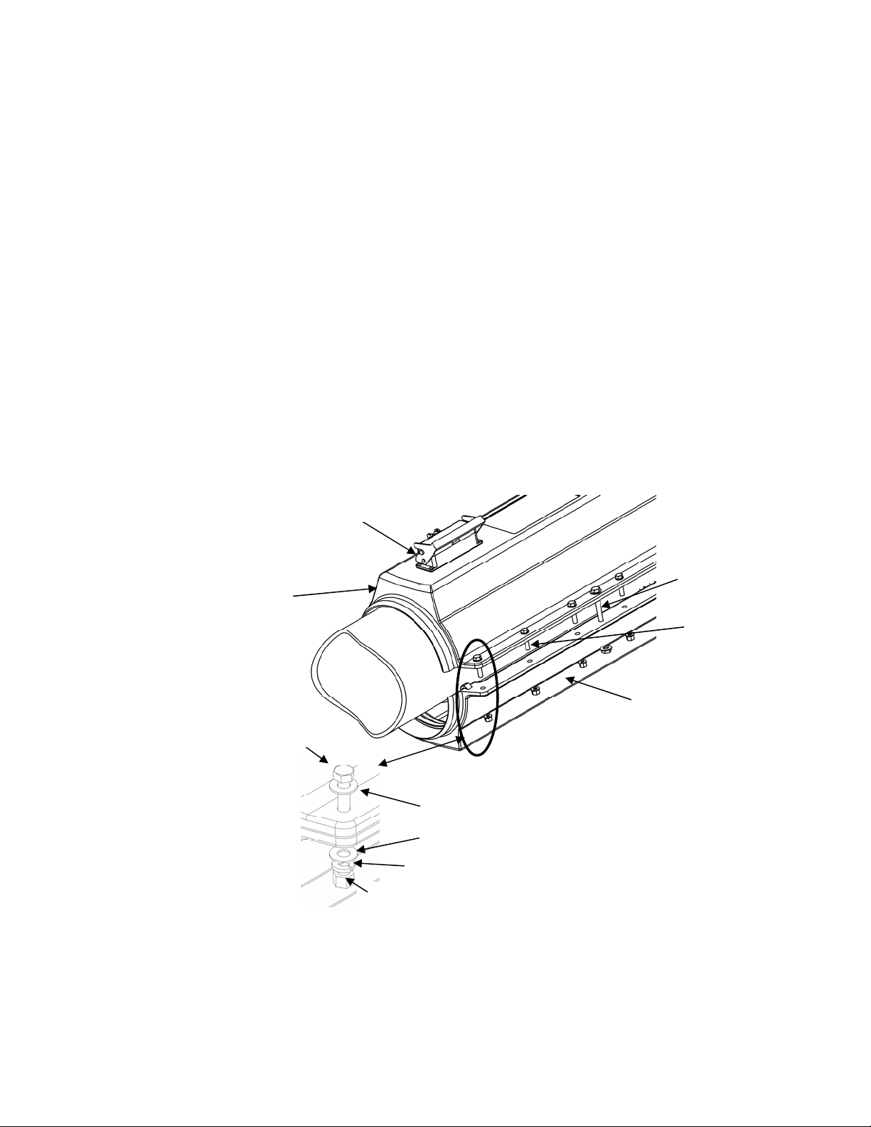
Transmitter cable connector
socket
Upper cover
assembly
Bolt
Nut
Cover bolt
Assembl
Washer
Washer
Lock washer
Alignment
bolts
(2 places)
Lower cover
assembly
Cover bolt
assemblies
(12 places)
Figure 15 Sensor Cover Bolt Installation
Copyright © 2006 CiDRA Corporation Page 7-11
20675-01 Rev 02
6
8
7
3
5
9
Tighten the alignment bolts 2 – 3 turns alternating between both sides
of the cover until the cover bolts protrude through the lower cover
assembly.
Note: Use of the alignment bolts may not be necessary if
the cover bolts and nuts can be made up.
Place a washer, lock washer and nut on the end of the sensor cover
bolt once it is through both halves of the cover and begin drawing the
cover halves together using the cover bolts. It is no longer necessary
to use the alignment bolts to draw the cover halves together.
Continue tightening the sensor cover bolts 1 - 2 turns in the tightening
sequence shown in Figure16. The gasket on the cover will compress
and the cover assembly halves will pull together. Tighten the cover
bolts until the two halves of the cover are drawn together so that there
are no gaps along the axis of the cover.
Note: There may be some
small gaps between the cover halves in between the bolts; this is
normal.
Alignment bolts
11
1
10
2
4
12
Figure 16 Sensor Cover Bolt Tightening Sequence
Note: The gaskets on the cover assembly will compress and conform
to the pipe surface during installation. Upon removal the gasket will
relax a little and will provide proper sealing if re-installed at the same
location from where it was removed.
CAUTION
The sensor cover gasket on fiberglass covers should be
replaced, if the assembly is moved to another pipe, to minimize
the potential for water leakage into the cover. Refer to rework
instructions (RI-0001) for information.
Following installation of the cover fasteners remove the alignment
bolts.
Copyright © 2006 CiDRA Corporation Page 7-12
20675-01 Rev 02
 Loading...