

Page 1

NA 12.54 D
12 - 2016
Control manual
V300
Page 2

Page 3
CONTENTS PAGE
1 - SAFETY/HANDLING GUIDELINES 2
1.1 General information 2
1.2 Protection against electrocution 2
1.3 Use 2
1.4 Warnings and danger: 2
2 - V300 3
3 - OPERATION 4
4 - USER TERMINAL AND RADIO-FREQUENCY TERMINAL 5
5 - DETAILS OF THE DISPLAY TERMINAL SCREENS 6
6 - MEANING OF SYMBOLS 6
7 - INSTALLATION PARAMETERS 7
8 - DIAGNOSTICS 9
9 - WIRING SCHEMATIC DIAGRAM FOR INDIVIDUAL UNITS 10
10 - MEASURING THE TEMPERATURE 11
11 - CHARACTERISTICS OF THE SENSORS USED BY THE V300 12
12 - MEASURING THE WATER TEMPERATURE 12
13 - RADIO-FREQUENCY TERMINAL 13
14 - MASTER/SLAVE FUNCTION 14
15 - PI CONTROL 17
16 - UNIVERSAL INPUTS 17
17 - CONNECTING THE FRAME CONTACT 18
18 - CENTRALISED MANAGEMENT WITH V300 19
19 - ELECTRICAL CONNECTIONS - CABLE TYPES 20
20 - TERMINAL DIMENSIONS 21
21 - USING THE USER TERMINALS 22
EN
Original text: French Version
EN - 1 N 12.54 D
Page 4

1 - SAFETY/HANDLING GUIDELINES
1.1 General information
Installation, start-up and maintenance operations for this equipment may be dangerous if certain factors particular to this
installation, such as the presence of electrical and live components and the installation location, are not taken into account.
Only trained, qualified installers and technicians, who have undergone specific training on the product in question, are authorised
to install and start up this equipment.
During any servicing operations, all the recommendations and instructions given in the maintenance brochures, on the labels or in
the instructions accompanying the equipment must be observed, along with any other applicable safety instructions.
- Observe all the regulations in the safety codes.
- Wear safety goggles and work gloves
- Handle heavy or bulky equipment with care when lifting, moving and setting down
1.2 Protection against electrocution
Only personnel qualified in accordance with the IEC (International Electrotechnical Commission) recommendations must be
allowed to access the electrical components. It is particularly recommended that all the electrical supplies to the unit are switched
off before any work is carried out. Cut the main power supply using the disconnect switch or circuit breaker.
Important: the V300 control system includes electronic components. These may cause or be subject to electromagnetic
disturbance if they are not installed and used in accordance with these instructions
Important: this equipment has been found to comply with the essential requirements of the directives in reference to the
following standards:
- Electromagnetic compatibility: 2014/30/EU
- Low voltage directives: 2014/35/EU
- Directive concerning the restriction of the use of hazardous substances in electrical and electronic equipment
(RoHS): 2011/65/EU
1.3 Use
This appliance is not designed to be used by persons (including children) with limited physical, sensory or mental
capabilities, or by persons with insufficient experience or knowledge, unless they are being supervised by a person
responsible for their safety or have received instructions on the use of the appliance from such a person.
Children must be supervised to ensure that they do not play on or with the appliance. Children must not be allowed to
carry out cleaning or maintenance work whilst unattended.
1.4 Warnings and danger:
Follow the precautions and instructions below to ensure your safety and that of your environment, and to prevent
damage to your equipment.
Warning : the equipment must be connected to an electrical system that conforms to
the standards in force in the country (NFC 15-100 in France). It must be equipped with
protection against overcurrent, overvoltage and earth faults.
Warning : for your own safety, it is essential to switch off and disconnect the equipment from
the mains before carrying out any work on it.
Warning : the safety of this product is only guaranteed if it is used as intended. Maintenance
may only be carried out by qualified personnel.
The PRODUCT must only be used indoors, at an altitude below 2000 metres.
NA 12.54 D EN - 2
Page 5
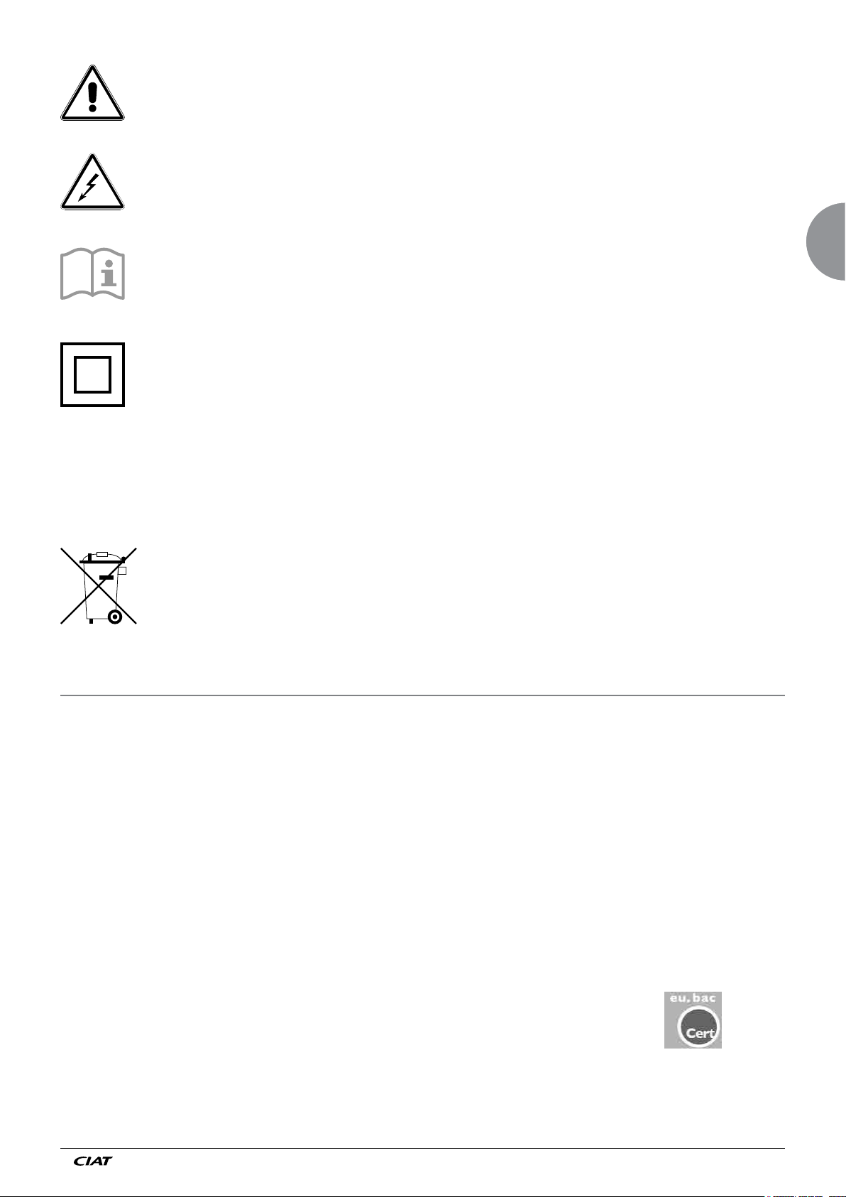
General danger : If the instructions are not followed, there is a risk of equipment damage.
Electrical danger : If the instructions are not followed, there is a risk of electrocution and
injury.
Read the instructions in this manual.
Part of Class II equipment
Protective device Devices that protect against overloads, short circuits and earth faults must conform to standard NF C 15-100,
and must be part of the building in which the equipment is installed. The circuit breaker must be designed for a nominal current
in Amperes that corresponds to the CIAT equipment model purchased.
Waste disposal by users in private households within the European Union.
EN
This symbol, either on the product or its packaging, indicates that the product must not be disposed of in ordinary
household waste. Instead, it is your responsibility to ensure that you dispose of your waste by taking it to a
designated recycling point for electrical and electronic devices. Separating your waste for recycling during disposal
helps preserve natural resources, protect the environment and safeguard health. To find your nearest recycling
centre, contact your local council, waste disposal service or the store from which you purchased the product.
2 - V300
CIAT's V300 control is designed for use with system-powered comfort units (AHUs, cassettes, etc.) in 2-tube, 2-tube/2-wire and
4-tube applications using recirculated air
It can be used to follow a time schedule (connected to the V300 zone timer as an option) and operate using a master/slave
function. It controls 230 V thermo valve actuators.
The V300 system comprises a controller integrated in the comfort unit and a user terminal for adjusting the setpoints and
operating modes.
The terminal is available in a wall-mounted wired version (to be connected to the controller by the installer), a flush-mounted
version (assembled and connected in the factory), and a radio-frequency version (terminal + receiver supplied in kit form)
Main functions:
- PI action
- Controlling a 3-speed or HEE fan, automatically or manually.
- Automatic heating/cooling switching with changeover sensor (2-tube application).
- 2 potential-free inputs for window switch, alarm or timer.
- 4 operating modes: Comfort/Economy/Frost protection/Off
Eubac certification
• The V300 controller is Eubac-certified under licence No.215472
• The corresponding CA values are as follows:
Applications: → 2-tube: Heating: 0,1 Cooling: 0,1
→ 2-tube/2-wire: Heating: 0,2 Cooling: 0,1
→ 4-tube: Heating: 0,1 Cooling: 0,1
• Labelling: AA
Note:
- These values are obtained with the CIAT NTC 10k Ω return air temperature sensor at 25°C
- These values can be viewed on the Eubac certification website: http://www.eubaccert.eu
EN - 3 N 12.54 D
Page 6
3 - OPERATION
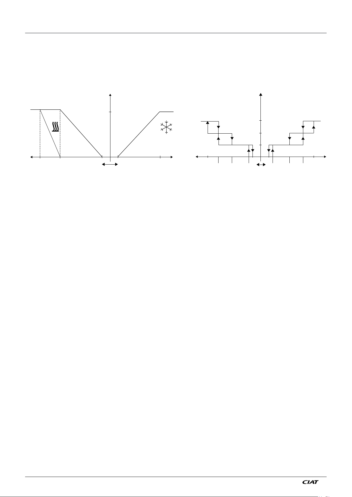
The control is Proportional and Integral. It controls the valve(s), the electric heater and the ventilation speeds (3 speeds + Auto
position) simultaneously.
Valve opening + electric heater *
Ventilation speed in deadband cutout (3 speeds)
Calculated by the PI algorithm
100 %
3
2
1
0
Proportional band
100 %
120 %
Electricity *
valve
Proportional band
HT CT HT CT
100 %100 %
100 %
80 % 80 %50 % 50 %10 % 10 %
* Case 2T2F
Deadband adjustable by 2 K min. Deadband adjustable by 2 K min.
When exiting the heating or cooling mode, the fan continues to operate for 2 minutes, thereby ensuring post-ventilation of the unit.
The potential electric heater power is modulated by a time-proportional signal using a 4-minute time base.
All calculations take place in the controller. The control terminal is used to adjust the temperature setpoint, switch between
automatic and manual ventilation, switch the unit on or to standby and, if applicable, to measure the room temperature.
The connection between the terminal and the controller is a 4-wire connection (2 shielded twisted pairs) with the shielding
connected to the comfort unit earth. (see pp.10 & 16)
Regulation on the air:
The regulation V300 also allows a functioning on the air (without gate(crack))
- In this case, the use of pumps of condensats on devices equipped with this mode of regulation stays of the responsibility of the
customer and/or the installer in case of dysfunction of this pump (risk of overflowing of the tub(ferry,high school diploma) of the
condensats of in the permanent irrigation of the cold battery(drum kit)).
- For vertical units equippedwith this control principle, the effect of the continuous radiation from the exchanger coil on the sensor
vill not enable the control system to function correcty. It is the customer's responsibility to find a suitablelocation for optimum
positioning of the sensor and satisfactory operation of the units.
NA 12.54 D EN - 4
Page 7
4 - USER TERMINAL AND RADIO-FREQUENCY TERMINAL
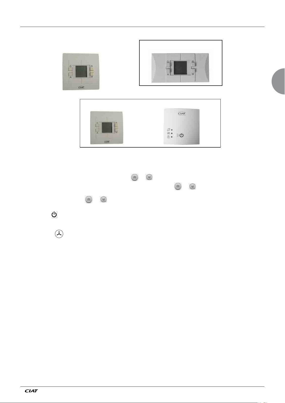
Wall terminal with
digital display
Radio + receiver wall-mounted terminal
1) Display:
This continuously displays the temperature detected by the sensor, the current operating mode, the chosen ventilation speed, and
any alarm present.
Flush-mounted terminal with digital display
EN
The desired temperature can be modified by pressing the
The temperature measured by the sensor is displayed again 8 seconds after the
It also displays error messages, reports windows opened or emergency switch-off activation, thereby enabling an initial diagnostic.
2) Temperature adjustment keys
and diagnostic values. +/- 4°K default setting (adjustable by parameter)
3) Standby key
chosen configuration).
4) Ventilation key
details below)
Note:
Different key combinations can be used to access:
- parameters
- diagnostics
- keypad lock
This enables you to change the operating mode (comfort, economy, frost protection or off according to the
. It is used to select the ventilation speed (Auto, 1, 2, 3) if the controller is in comfort mode (see display
or . These enable you to adjust the temperature setpoint and also access the set-up
or keys
or key was pressed
EN - 5 N 12.54 D
Page 8
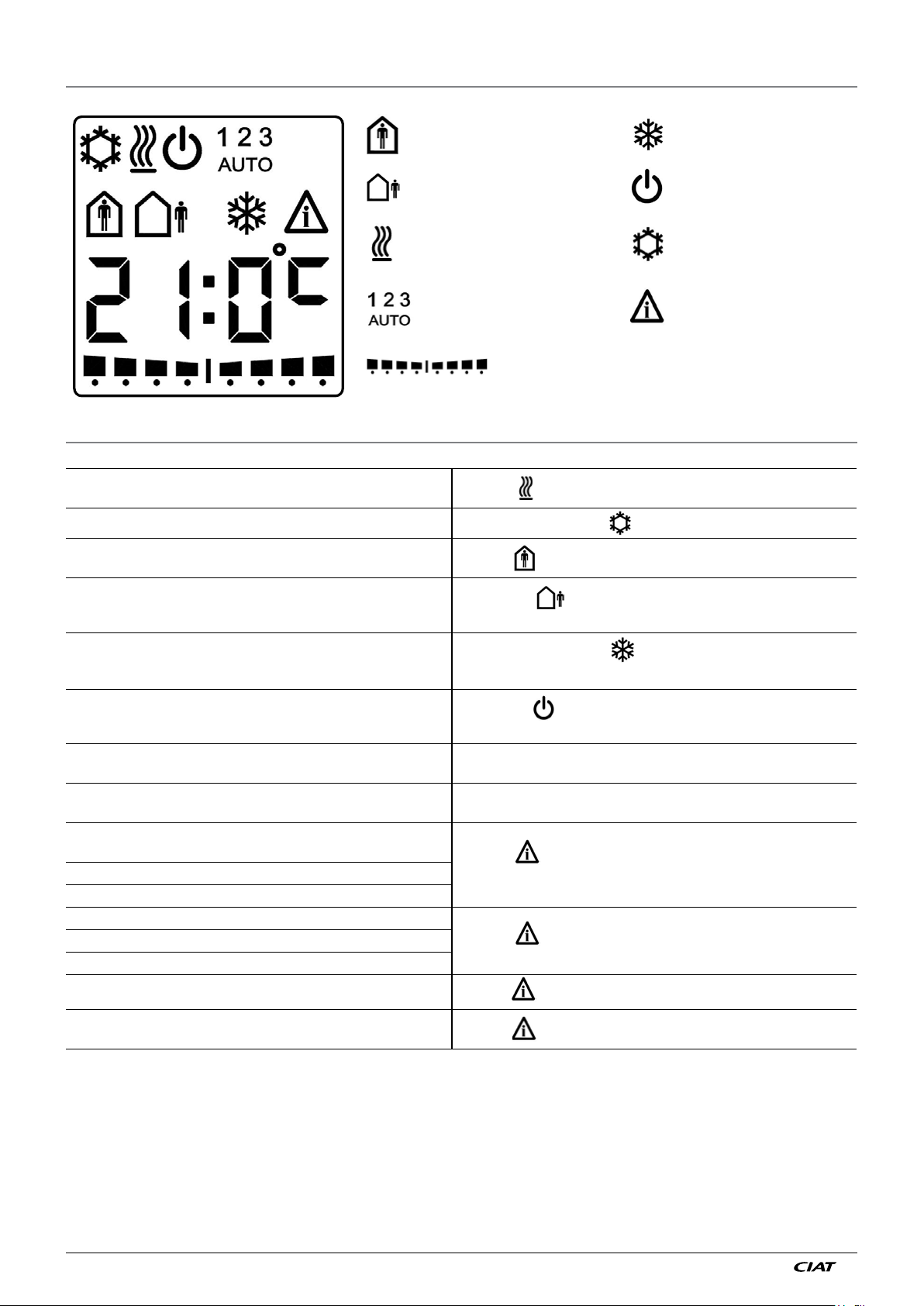
5 - DETAILS OF THE DISPLAY TERMINAL SCREENS
: Comfort mode
: Economy mode
: Heating in progress : Cooling in progress
: Manual ventilation speeds
: Automatic position
: Setpoint shift bar chart
6 - MEANING OF SYMBOLS
Heating
Refrigeration Air conditioning symbol fixed
Comfort
Heating
Symbol
symbol fixed
: Frost protection mode
: Off mode
: Alarm and fault
Economy set using the zone timer or sleep button on the
terminal (depending on configuration).
Frost protection by window contact
Frost protection set using the zone timer or sleep button on
the terminal (depending on configuration).
Off set using the zone timer or sleep button on the
(depending on configuration
Setpoint adjustment
Ventilation
Indoor environment sensor fault if indoor environment sensor
assigned priority
Return sensor fault if return sensor assigned priority
Simultaneous fault on indoor environment and return sensors
Condensate drain pump alarm
Fan motor assembly unit alarm (if HEE)
General alarm
Master unit but communication lost with slave(s)
Master or Individual unit but communication lost with the
Zone timer
).
terminal
Eco symbol
No ventilation indication
Frost protection symbol
No ventilation indication
Off symbol
No ventilation indication
Setpoint adjustment depends on the configuration (± 4°K by
default)
1, 2 or 3: LS, MS or HS manual selected
AUTO: ventilation controlled automatically by the controller
Symbol
Symbol
Symbol (see d07 = 1.0.0)
Symbol (see d08 = 2)
(see d07 = 0.0.1)
(see d07 = 0.1.0)
NA 12.54 D EN - 6
Page 9
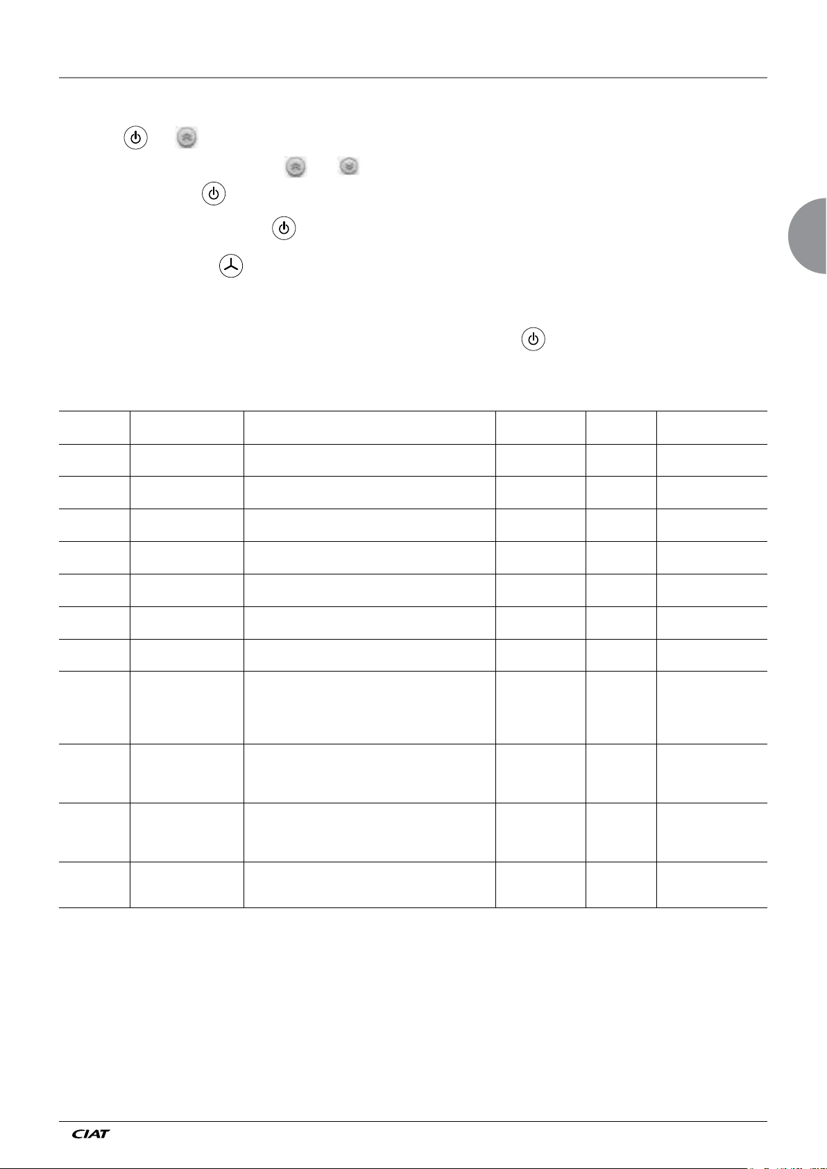
7 - INSTALLATION PARAMETERS
• The installation parameters can be modified using the room terminals with display.
• To enter Configuration mode:
- Press the and keys simultaneously for 5 seconds
→ Parameter P01 appears
- Select the desired parameter using the and keys
- To consult a parameter: key
- To confirm a parameter modification: key:
→ The modified value flashes for 2 seconds then the parameter No. appears again fixed: the new value is saved
- To exit configuration mode: key
→ When exiting the "parameter" menu, this is shown for approximately 2 seconds before the display returns to normal
(time to reset the controller)
• If there is no activity for 5 consecutive minutes, the terminal automatically exits the configuration mode
and returns to the normal display. (any configuration modifications not confirmed by will not be saved).
Parameter Name Explanation Setting range
P01 Zone number
P02 Heating comfort setpoint
P03 Cooling comfort setpoint
P04
P05
P06
P07
P08
P09
P10
P11
Economy heating
setpoint
Economy cooling
setpoint
Comfort setpoint setting
range
No comfort setpoint
adjustment
Operating mode
activated by sleep button
on user terminal.
Temperature displayed
on terminal
Setpoint offset value
display
Temperature sensor
selection (if recycled air
application)
This zone number allows a link to be created with the V300
Zone timer
Setpoint for heating control in comfort mode P04 + 0.5...P03-2.0
Setpoint for cooling control in comfort mode P02 + 2.0...P05-0.5
Heating control setpoint in economy mode P53 + 0.5...P02-0.5
Cooling control setpoint in economy mode P03 + 0.5...40
Adjusts the maximum +/- shift of the setpoint for room units 0.0...9.0 resolution
Defines the display resolution for the comfort setpoint shift
on the room units
0 = Comfort → Off
1 = Comfort → Frost protection
2 = Comfort → Economy
3 = Comfort → Eco → Frost protection → Stopped →
Comfort
Actual temperature display on the indoor environment
device LCD:
1 = Setpoint
2 = Measurement
Display of actual temperature offset value:
1 = Not displayed (bar chart)
2 = Display offset + bar chart
3 = Display setpoint + bar chart
Control sensor selection
0 = Return sensor priority
1 = Master room sensor priority
1...6 1 X
increments of 0.5
increments of 0.5
increments of 0.5
increments of 0.5
defined by P07
0.5 : 1.0 1.0 X
0...3 1 X
1 : 2 2 X
1 : 2 : 3 1 X
0 : 1 1 X
Default
value
19.0 X
26.0 X
14.0 X
32.0 X
4.0 X
EN
Param. written on
slave
EN - 7 N 12.54 D
Page 10
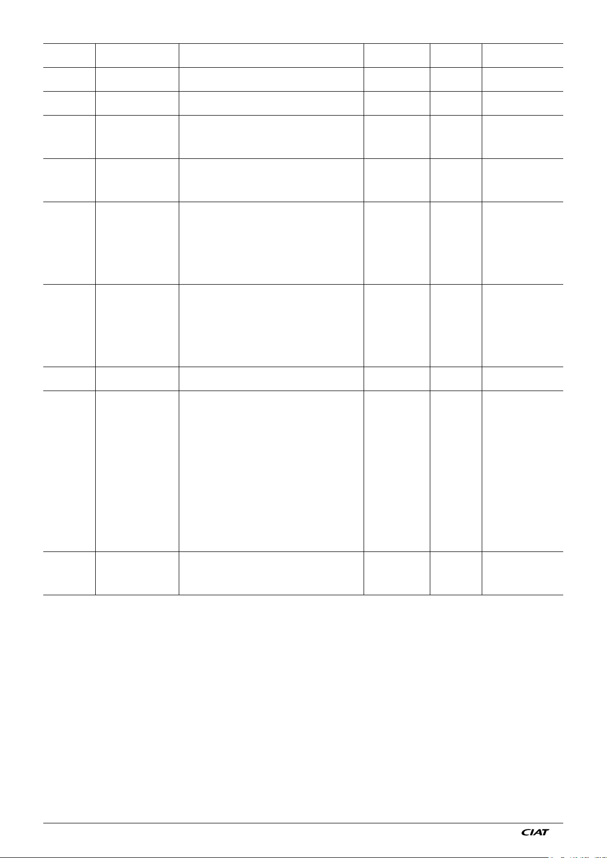
Parameter Name Explanation Setting range
P12 Sensor S1 calibration
P13
Indoor environment
sensor calibration
Action direction of
P14
auxiliary contact on
input D1
Action direction of
P15
auxiliary contact on
input D2
Correction factor for sensor S1 - 9.9...+ 9.9
resolution of 0.1
Correction factor for the room sensor - 9.9...+ 9.9
resolution of 0.1
The auxiliary contact on input DI1 may be normally closed
or normally open:
0 = Normally open
0 : 1 1 X
1 = Normally closed
The auxiliary contact on input DI2 may be normally closed
or normally open:
0 = Normally open
0 : 1 1 X
1 = Normally closed
This parameter allows the input to have several functions:
0 = Inactive on control
1 = Frost protection
P16 Input D1 function
2 = Economy
3 = Alarm
0...6 1 X
4 = LS air purification
5 = MS air purification
6 = Off
This parameter allows the input to have several functions:
0 = Inactive on control
1 = Frost protection
P17 Input D2 function
2 = Economy
3 = Alarm (HEE motor)
0...6 3 X
4 = LS air purification
5 = MS air purification
6 = Off
P18 Number of fan speeds
0 = 3 speeds in all modes
1 = 3 speeds in comfort mode/2 speeds in reduced mode
0 : 1 0 X
0 = Ventilation off in all modes
1 = Periodic restarts in comfort mode/off in economy and
frost protection mode
2 = Periodic restarts in all modes
3 = Permanent ventilation in comfort mode/off in economy
and frost protection mode
4 = Permanent ventilation in comfort mode/periodic restarts
P19 Deadband ventilation
in economy and frost protection modes
5 = Permanent ventilation in cooling comfort mode/off in
0...7 0 X
heating comfort, economy and frost protection mode
6 = Permanent ventilation in cooling comfort mode/
periodic restarts in heating comfort, economy and frost
protection modes
7 = Permanent ventilation in cooling comfort mode/periodic
restarts in heating comfort mode/off in economy and
frost protection mode
0 = Electric heater disabled
P20 Electric heater operation
1 = Electric heater in main heating mode only
2 = Auxiliary electric heater only
0 : 1 : 2 : 3 3 X
3 = Electric heater in main heating + auxiliary mode
Default
value
0
0
Param. written on
slave
NA 12.54 D EN - 8
Page 11
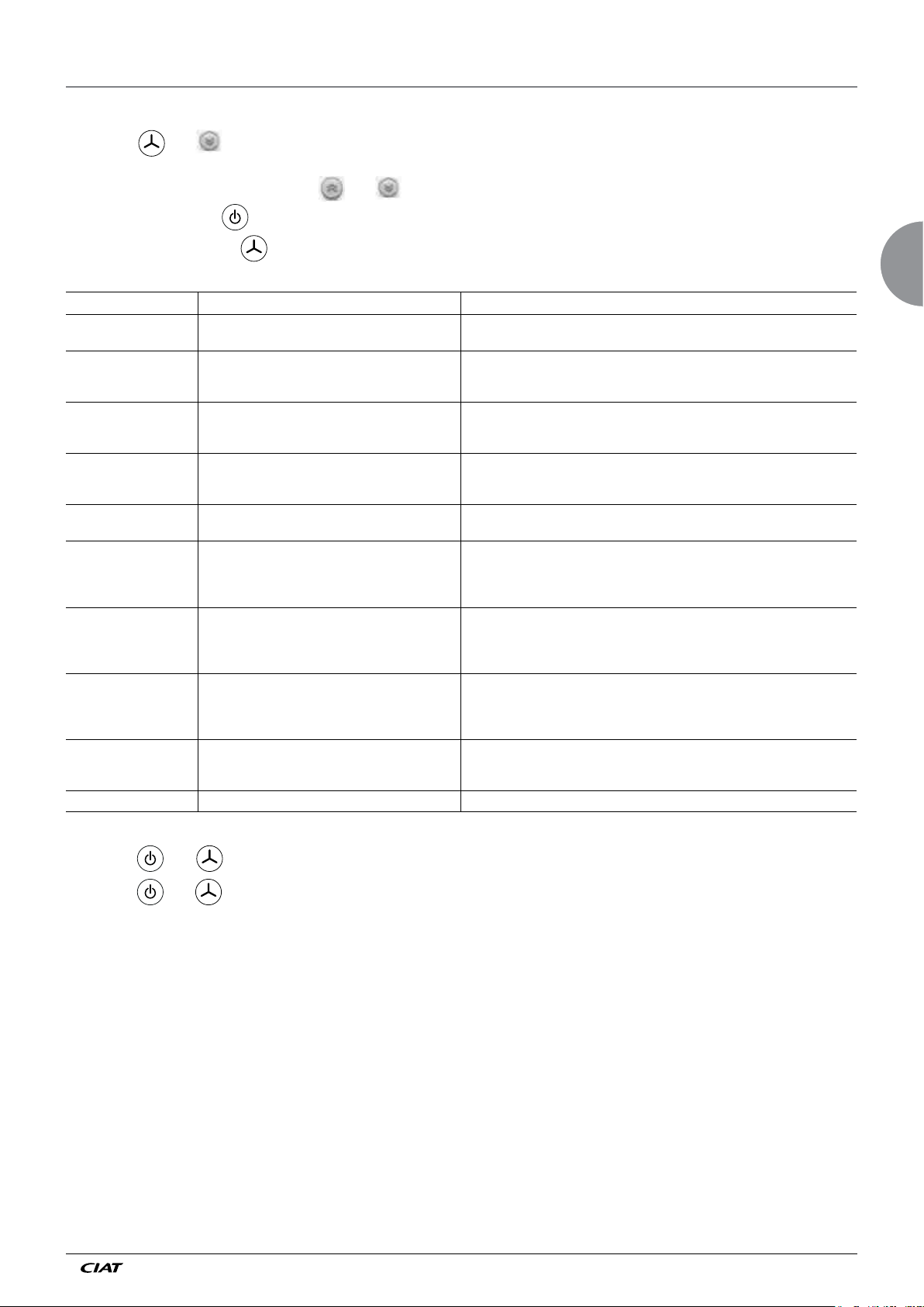
8 - DIAGNOSTICS
To enter "Diagnostic" mode:
- Press the and keys simultaneously for 5 seconds
→ diagnostic d01 appears
- Select the desired diagnostic using the and keys
- To consult a diagnostic: key
- To exit "Diagnostic" mode: key
Diagnostics Name Explanation
d0 Master/slave unit Number of slave controllers detected by the master (if the terminal is connected to a
d1 Control state 0 = Heating request in progress
d2 Changeover state 0 = Hot water
d3 Heating/cooling authorisation state 011 = Heating and cooling authorised
d4 Electrical authorisation state 0 = Electric heating bypassed
d5 Mode active 0 = Off
d6 Digital input state 000 = DI2 closed / DI1 closed
d7 Alarm 000 = No alarm
d8 Communication with zone timer 0 = No communication since the last reset
d9 Controller software version
slave, number of slaves connected after this slave).
1 = Cooling request in progress
2 = Deadband
1 = Cold water
2 = No water (water neither hot nor cold)
001 = Heating authorisation
010 = Cooling authorisation
1 = Electric heating authorised
1 = Frost protection
2 = Economy
3 = Comfort
001 = DI2 closed /
010 =
DI2 open
011 =
DI2 open
001 = Sensor fault (room or return)
010 = Alarm via input D1 or D2
100 = Loss of communication with one or more slaves
1 = Communication OK
2 = Communication interrupted
DI1 open
/ DI1 closed
/ DI1
open
EN
Sequence to lock/unlock the keypad keys:
- Press the and keys simultaneously for 5 seconds: the keypad is locked
- Press the and keys simultaneously for 5 seconds: the keypad is unlocked
EN - 9 N 12.54 D
Page 12
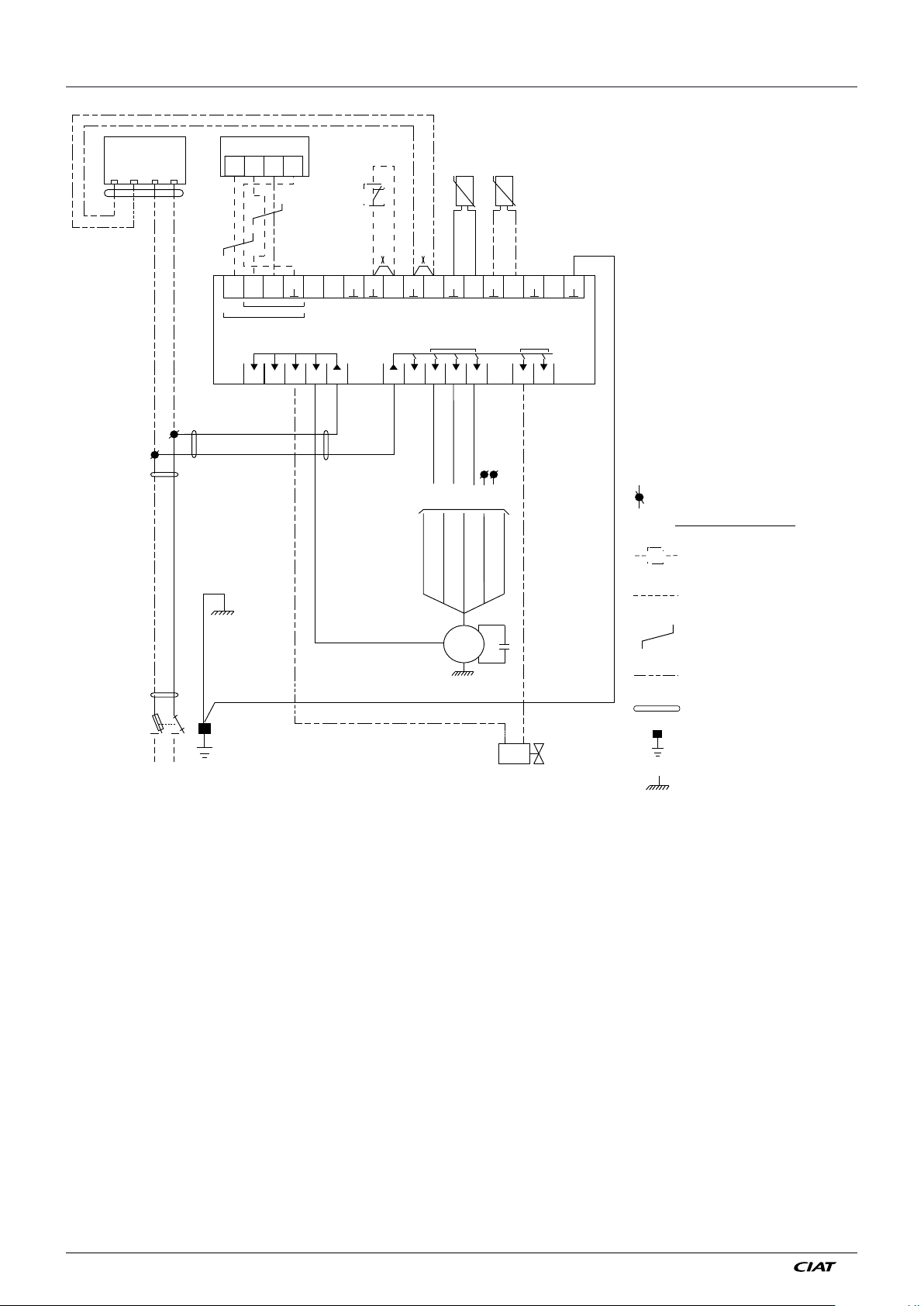
9 - WIRING SCHEMATIC DIAGRAM FOR INDIVIDUAL UNITS
A
C NC P N
Brown
Blue
PR
A
20 21 22 23
23
22
5V20A21B
MASTER SLAVE
TERMINAL
V300
KF
28
26
24 25
A B D1 D2 S1 S2
POWER IN
230 V
N
27
L
BS
Grey
Black
29 30
31 3233343536
3A 0,1A
10A
BSA
0-10V
37
BS
BSA
D
KF
MK
PR
User terminal
Return temperature sensor
Changeover sensor
Controller
Window switch
Air handling fan
Pump unit
Green/Yellow
Q
X
Y
Fused isolator
Shunt (remove if
equipment connected)
Solenoid valve
Connection terminal
Equipment to be provided by
the customer CIAT assembly
optional
Customer connection
Shielded twisted pair
Customer connection
if component supplied
separately
Multi-conductor cable
Earth terminal
2
Brown
2
1
Q
L
1
Blue
N
N
D
Blue
Brown
Green/Yellow
Blue
Blue
Ivory
Shared
Green/Yellow
06 07 08 09 10 11 1201 02 03 04 05
PVMVGV
Brown
Speed selection as per ARC
V1V2V3V4V5
Green
Blue
Yellow
Grey
MK
Cd
Brown
Black
Y
Earth
Controller/Terminal connection: shielded twisted cable: see p20
Shielding to be connected to terminal 23 on the controller and terminal end
Certain problems may be resolved by checking some fundamental points. Check using the list below before requesting servicing.
Warning: When the controller is switched on, control will only take effect after a few minutes of system initialisation. (the terminal
segments come on approximately every 2 seconds)
Upon a mains power cut:
1. When the power returns, the controller restarts in Comfort mode in all cases:
→ However, it does not store:
- The setpoint override (returns to the midpoint)
- The ventilation speed (returns to Auto)
2. Error message: diagnostic d07 gives the controller's Alarm state.
NA 12.54 D EN - 10
Page 13
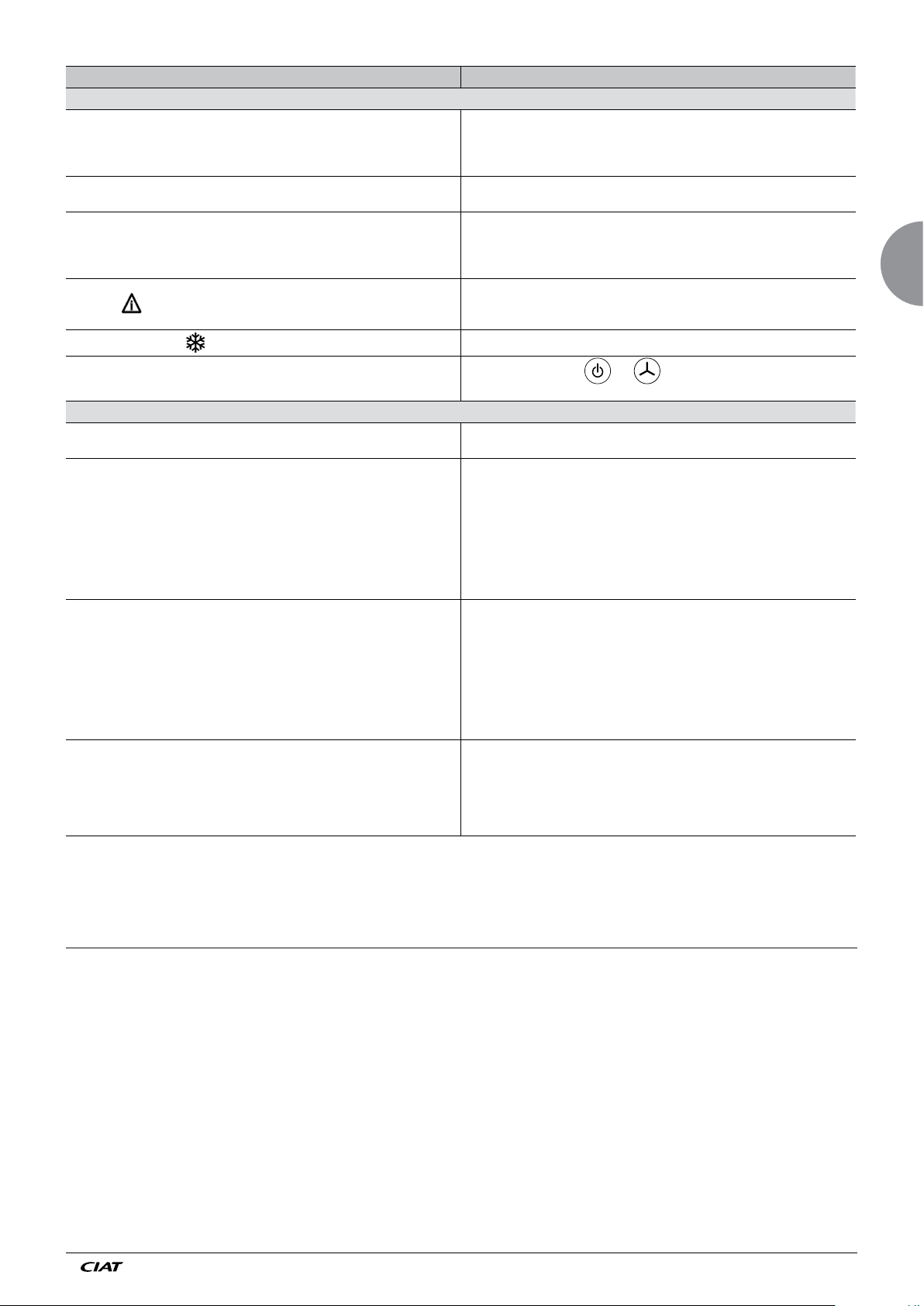
Terminal switched off in comfort mode
IRREGULARITY SOLUTION
USER TERMINAL
- No 230V supply (check fuse, fused isolator, controller connection)
- Check the electrical connection between the terminal and the controller:
Reversal of "5V and ┴" wires (refer to the wiring diagram)
The terminal remains 100% on (all segments lit)
The terminal is on but remains locked without Alarm and keys inactive.
Display
Frost protection display
The terminal is on but no keys are operational
The valves close instead of opening and vice-versa
No heating
No refrigeration
The fan always remains at high speed.
Check the electrical connection between the terminal and the controller:
Reversal of wires on terminals A and B.
. Wiring error in a Master/Slave unit: Reversal of wires on terminals A and B with
the first slave in the loop.
. The terminal is wired to a slave unit
. The keypad is locked using a combination of keys.
- Check the condensate pump, the condition of the condensate pan, alarm contact
on D1 or D2.
- See value of d07
Window open or "Frost protection" command via V300 zone timer
Keypad locked: press the and keys simultaneously for
5 seconds to lock or unlock the keypad.
COMFORT UNITS
- If the controller has just been powered on, wait for the system to initiate (6 mins).
- Check the electrical connection of the valves (refer to wiring diagram).
- Check that:
. The heating setpoint T°C is greater than the measured and displayed temperature
. Any shunt in case of a 2-tube (hot water coil only) is present between terminals S2
and ┴ (refer to wiring diagram)
. Any room changeover sensor, in case of a reversible 2-tube coil, is correctly
electrically connected and that the sensing element is in contact with the water
inlet pipe.
. The controller is correctly set up (refer to the Installation parameters procedure)
- If operating with an electric heater, check that the T°C limiter is activated.
- Check that:
. The cooling setpoint temperature is less than the measured and displayed
temperature
. Terminals S2 and ┴ are not connected by a shunt in case of a cooling-only 2-tube
configuration, with or without electric heater
. Any room changeover sensor, in case of a reversible 2-tube coil, is correctly
electrically connected and that the sensing element is in contact with the water
inlet pipe
. The controller is correctly set up (refer to the Installation parameters procedure)
- Check that:
. The water inlet T° is correct
. The water flow rate is sufficient
. The installation has been correctly bled
. The control parameters are suitable (proportional band, integral time).
. The ventilation is not in manual position III.
EN
10 - MEASURING THE TEMPERATURE
The V300 offers the possibility of controlling the air temperature via a return sensor or a room sensor (P11).
If you can choose between the two, it is preferable to opt for the indoor environment sensor, since it provides a better picture of
the room temperature.
The indoor environment sensor is situated inside the user terminal unit. When it is used, particular care must be taken in choosing
the location of the user terminal in the room (do not expose it to sunlight, or place it on top of a device giving off heat - put it on
an inside partition).
The end of the wiring conduit must be heat insulated.
EN - 11 N 12.54 D
Page 14
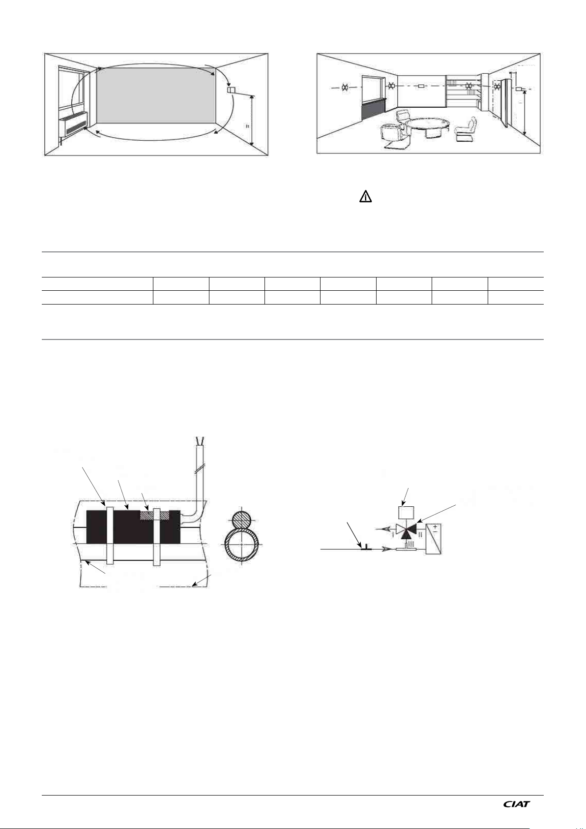
20 cm
min.
150 cm
150 cm
The sensor can be chosen using setting P11 (=0: return air sensor; =1: indoor environment sensor).
If the selected sensor is faulty, the other sensor immediately takes over. A symbol is displayed on the screen and the fault can
also be looked up in the variable of diagnostic d07.
The sensor measurement can be corrected by means of parameter P12 (return sensor) or P13 (room sensor).
11 - CHARACTERISTICS OF THE SENSORS USED BY THE V300
All the sensors used by the V300 (return, changeover) have the same specifications
Temperature °C 5 10 15 20 25 30 35
Resistance Ohms 22 050 17 960 14 690 12 090 10 000 8 313 6 940
12 - MEASURING THE WATER TEMPERATURE
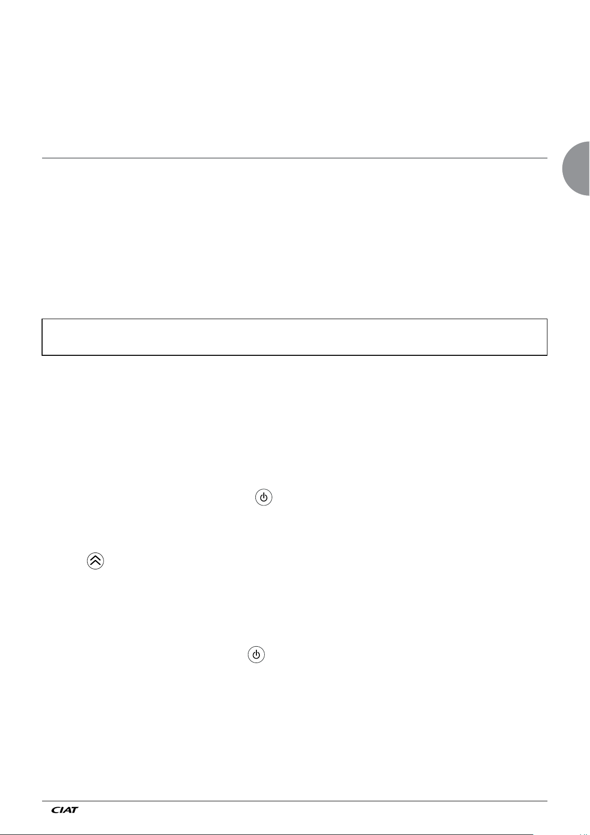
Two-tube heating/cooling comfort units may be fitted with a water temperature sensor (or changeover sensor). It must be
positioned by the installer upline of the 4-way valve (water network end). It is fixed to the pipe using electrician's clips and located
underneath the pipe's thermal insulation.
Position and use of the changeover sensor
Clamp
Sensor adapter
Sensor
Water inlet pipe
Sensor
Insulation
Valve motor
3-way valve with
built-in bypass
(often called a
4-way valve)
- Changeover operating algorithm:
• If the changeover sensor measures a water temperature greater than 7°C (P48 adjustable) at room temperature, the water is
deemed to be hot.
• If the changeover sensor measures a water temperature lower than 4°C (P49 adjustable) at room temperature, the water is
deemed to be cold.
• If the changeover sensor measures water temperature between these two values, the water is deemed neutral.
- Changeover operation with water at neutral temperature:
In this scenario, and if the controller requirement is confirmed, the V300 launches a test cycle on the valve so as to check the
network's available water temperature (valve 100% opened to authorise water circulation in the terminal unit coil).
- If this temperature does not vary, the V300 keeps the same status
- If this temperature varies and returns to the conditions described above, the V300 re-authorises its control cycle.
NA 12.54 D EN - 12
Page 15
Warning: the changeover sensor measures the surface temperature of the piping. There is an obvious difference between the
actual water temperature and the surface temperature. The water speed will therefore be selected so as to guarantee changeover
switching.
For P47 = 1, if nothing is connected between terminals S2 and ┴, the controller deduces that the water circulating in the coil is still
cold. If there is a bridge between these terminals, the controller deduces that the water is still hot.
For P47 = 0, the controller waits for the water temperature value from the V300 zone timer in order to start heating or cooling (if it
does not receive a value, it will automatically operate in "heating mode" to ensure safe heating and frost protection, or in "cooling
mode" on 2-tube + 2-wire applications).
13 - RADIO-FREQUENCY TERMINAL
. The radio-frequency terminal can only be used with its radio-frequency receiver.
. The radio-frequency receiver is supplied in kit form and must have been pre-installed on the comfort unit using the support
bracket supplied with the kit
. The terminal functions are identical to those of the wired wall-mounted terminal. This is fixed to the wall in the same way (see
dimensions and drilling instructions for the unit).
. The receiver and the terminal periodically exchange information (setpoints, ventilation speed, etc.)
These exchanges may take longer than with a wire terminal and need a few seconds.
. The radio-frequency terminal operates with 2 LR03 type alkaline batteries (supplied). These batteries should be replaced once
a year (depending on use).
Battery
- 2 LR03/AAA 1.5V alkaline batteries
- Match the +/- polarity
- The batteries supplied are not rechargeable
Warning : there is a risk of explosion if the battery is replaced with the wrong type. Dispose of used batteries in accordance
with the instructions. When replacing batteries, make sure the product is correctly and completely refitted.
IMPORTANT for Switzerland: Annex 4.10 to the norm SR 814.013 is applicable to batteries.
EN
Configuring the terminal with its receiver
. Radio receiver:
Indicator 1 (blue) : - Flashes = receiver not paired rapid flashing = receiver not paired
- On = pairing (or unpairing) in progress slow flashing = pairing (or unpairing) in progress
- Off = receiver paired
Indicator 2 (orange) : - Flashing when information is sent or received regular flashing = loss of communication between the
receiver and the terminal.
Indicator 3 (green) : - Indicates operation in comfort mode (once pairing is complete)
- The receiver key then acts as the unit's On/Off key
- Comfort operation: indicator on; off for all other modes.
. If the terminal is not linked to a receiver, the display shows: "CF 0"
. If the terminal shows "CF 1", it is linked to a receiver:
to access the configuration menu, press and hold the key for 5 seconds.
. When powered up :
- Indicator 1 (blue) on the receiver flashes rapidly
- Set the receiver to configuration mode by pressing and holding its key for 5 seconds: indicator 1 (blue) flashes slowly
. On the terminal :
• Press the key: the display shows "Add": pairing starts (approximately 5 to 8 seconds)
• When the sequence is complete, the terminal display returns to its normal screen (temperature display, etc.).
- Indicator 1 on the terminal goes out
- Indicator 3 on the terminal comes on if comfort mode is active on the terminal (off for all other modes)
- This allows the user to check the communication between the unit and the terminal using the receiver key (which acts
as the On/Off key) via the current mode display.
- The display will then show "CF 1" in the configuration menu
- To delete the links between a terminal and a receiver which are already linked:
- On the terminal: enter configuration mode key for 5 seconds) until the display shows "CF 1"
EN - 13 N 12.54 D
Page 16
Press the button The display becomes "del"
Deconfiguration is done automatically. The sequence is completed as soon as the display becomes "CF O". From this moment,
the terminal and its receiver are unapplied
In the case or "CF2" appears on the display(posting), it indicates that the désapairage of the terminal was made while the
communication with his(her) receiver was broken.
In this case of figure :
Rest(Support) again on the sideline So as to have the display(posting) " CF 0 " (CF 0 = désapairé terminal).
Désapairer the receiver in a individual way: rest 5s the button Of the receiver. The blue clairvoyant(light) (1 ) quickly flashes.
The receiver is désapairé.
. Using the remote control:
- After 30 seconds without use, the terminal will go to standby (display switches off) to save the batteries. To "wake"
the terminal, press any key. The display "----°C" appears on the screen, flashing for a few seconds, while it synchronises with its
receiver.
. Battery change indicator:
- When the terminal has been woken, if "bAt" appears for a few seconds (rather than flashing "----°C") the terminal
batteries must be replaced.
- In the case or "beats" if fixed speed(look), piles cannot assure(insure) any more the food(supply) of the terminal.
Compulsory change of piles.
14 - MASTER/SLAVE FUNCTION
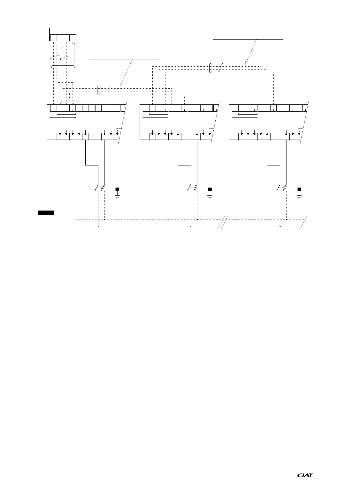
A master can control up to 15 slaves.
Two wires + shielding lead from the master unit to the first slave. Two wires + shielding lead from the first slave to the second
slave, etc.
Wires do not have to lead out from the last slave. The distance between two controllers must not exceed 30 m (see cable
characteristics on p16)
The master communicates the following information to the slaves:
● Setpoints
● Air temperature
● Water temperature
● Current mode
● Manual ventilation speed
● State of inputs D1 and D2.
It is possible (via P11) to set the slave units on the return air sensor (e.g. open plan offices).
A slave must not have a room unit.
The operation resulting from the combination of the Off, Frost protection, Economy, Comfort, Window open states between the
master and the slave is designed to reduce energy consumption to the minimum.
Starting up a Master/Slave unit:
. The Master and Slave units are detected automatically.
→ The master is the unit at the head of the master/slave bus
→ When the loop is powered up, the master automatically detects the slaves connected downstream of it (see
wiring diagram below)
→ Check the number of slaves connected to the Master via diagnostic d00
→ If the number does not match, check the wiring
→ Set any parameters on the Master (new setpoint, etc.); they will automatically transferred to the connected slaves
(see list pp 7 and 8)
→ Set any parameters on the Slaves (control on return sensor, etc.)
Two scenarios:
● If the setting is entered on the first Slave in the loop, all the slaves located below it will have the same settings.
● If only one slave is affected: temporarily disconnect its bus to separate it during the setting procedure.
→ It is possible to transfer all the parameters (see list pp 5 and 6) from a master to all of its slaves (when replacing a
Slave controller): see p55 = 3
→ If the master/slave connection is broken, all the slaves located downstream of the break will switch to "Standalone"
mode and retain their operating status during the break.
→ The master terminal will then display the symbol; the d07 will provide the information on the "loss of
communication with the slaves": d07 = 1.0.0 (see § Diagnostics p9)
NA 12.54 D EN - 14
Page 17
. It is possible to diagnose units still being controlled by the terminal and find out via the d00 how many slaves are still connected
by pressing the key.
. The limit for a master/slave loop is 15 slaves max. per master (see schematic diagram with maximum cable length between
master and slave)
. If a slave still has a room terminal, check that P09 = 2 imperative.
It will display the state of this Slave controller + the T° measured by the Master (if room sensor priority) or the T° measured by its
own sensor (if return sensor priority), as the keypad keys are inactive (parameters and diagnostics for this slave are accessible
for diagnostic purposes)
Inputs D1 & D2:
. If Input configured with "Alarm" (condensate pump, motor fault, etc.):
→ If alarm on the master:
The master is powered off and displays and ; the keypad keys are locked.
The slaves on the loop continue to operate in the last state indicated by the Master.
The slaves remain controlled by the V300 Zone timer, if included.
→ If there is an alarm on one of the slaves:
Only the slave concerned is powered off, the other units continue to operate as per the orders from the Master and its room
terminal.
. If the Input is configured to one of the 4 operating modes:
→ If triggered on the master:
The entire Master/Slave loop switches to the mode defined by the input configuration.
Only a lower mode may be set using the wall-mounted terminal (depending on the sleep button configuration)
For window switches: (Frost protection mode):
They must all be connected in series to the Master
→ If triggered on one of the slaves:
Only the slave concerned switches to the mode defined by the input configuration.
Setting the parameters on a Master/Slave loop:
Modifying a parameter on the Master unit will also modify the Slave unit
→ See Parameters table including the list of parameters sent from the Master to its Slaves (pp 7 & 8)
→ Warning: Modifying one parameter directly on a slave in the loop will modify the same parameter on all the slaves
located below it. To modify only the slave concerned, disconnect the bus (via the quick connector) and connect a terminal to carry
out the operation.
EN
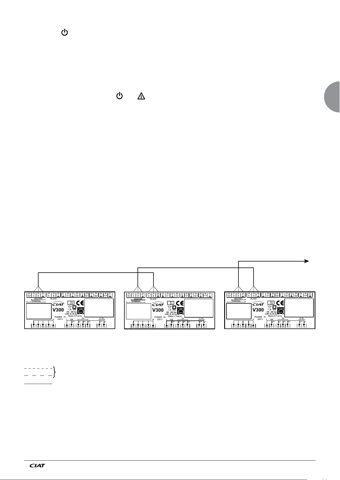
Connection diagram: Master/Slave
V300 Master V300 Slave 1 V300 Master 2
1 x Twisted pair
Shielding
(1) To Slave N: terminals 24, 25 - 30 metres maximum
Mark the buses in preparation for maintenance or site developments.
(2) Shielding: mandatory continuity/terminal = 23.
See diagram 7415354
(1)
(2)(2)(2)(2)
EN - 15 N 12.54 D
Page 18
21 2220 23
A
Max. length of bus cable between the master and the 1st slave:
Max. length of bus cable between 2 slaves: 30m
30m including cable length for room terminal
20 21
5V A B
TERMINAL TERMINAL
D
230/ 1/ 50
POWER SUPPLY
CONTROLLER/FAN
24 25 26
22 23
MASTER MASTER MASTER
A
V300
01 02 03 04 05
L
N
27 28 29 30
B
SLAVE SLAVE SLAVE
D1
MASTER
POWER IN
230 V
LN
06 07 08
Blue
Brown
Q
N 1
N
31
D2
3A
10A
F1
EH
2
L
D
20 21
5V A B
01 02 03 04 05
22 23
V300
24 25 26
A
B
POWER IN
230 V
Blue
Q
27 28 29 30
D1
SLAVE 1
10A
LN
EH
06 07 08
31
D2
3A
F1
D
20 21
5V A B
TERMINAL
01 02 03 04 05
Brown
2
N 1
LN LN
MAX 15 SLAVES
MASTER/SLAVE ARCHITECTURE
22 23
V300
24 25 26
A
27 28 29 30
B D2
SLAVE ..N
POWER IN
230 V
Blue
Q
N 1
D1
10A
LN
EH
06 07 08
Brown
2
31
3A
F1
NA 12.54 D EN - 16
Page 19
15 - PI CONTROL
The control parameters (proportional band, integral time) are preset in the factory. Precise values have been validated in the
laboratory and enable "Comfort" operation in most comfort unit applications. Modifications to these remain the user's responsibility.
Deadband ventilation
In the comfort operating mode, the deadband ventilation is set in the factory as follows:
. Comfort mode (P19): 0 Fan stoppage (if controller with room sensor) or 1: periodic restarts (if controller with return sensor).
It is possible either to cut off the ventilation after 2 mins of post-ventilation (P19 = 0), or have constant low speed ventilation (P19
= 3), or have constant ventilation in the summer and for it to cut out in the winter (P19 = 5), i.e. ventilation on every 30 mins for 1
minute (P19 = 2).
If control is applied using the return sensor, it is strongly recommended to have continuous low speed ventilation.
The setting of these parameters is derived from a compromise between control precision, physiological comfort and energy
saving (see details of P19 in the parameters table).
Note: For air control (without valves), make sure that P19 is set to 0 to avoid problems with overheating or cooling caused by the
ventilation.
Minimum ventilation time
In automatic ventilation, the controller automatically engages the ventilation speeds. To limit the number of ventilation speed
changes, there is a stipulated minimum ventilation run time of 2 minutes at each speed.
Comfort override delay
To control energy consumption, the controller may limit the operating time in comfort mode following a user override. Parameter
P54 enables you to set a timer between 1 hr and 12 hrs, or to prohibit any comfort override (P54 = 0). This function can be
disabled (P54 = 13). It is generally used with a zone timer (see corresponding instructions)
Operating mode activated by standby key
Depending on parameter P08, the sleep button can be pressed to switch between the controller's 4 operating modes: Comfort,
Economy, Frost protection and Off.
2-pipe + radiator application or 2-pipe + electric convector application
The control enables one radiator equipped with a 230V thermostatic valve or an electric convector (230V/2000W max) to be
actuated via P21 = 2
EN
In this case, during the heating sequence, the V300 control stops ventilation
of the comfort unit and triggers the connected electric convector or radiator valve in on/off mode.
The electric convector must then be wired directly to the V300 control
via the dedicated output for the electric coil (230V/2000W max) / the 230V thermostatic valve can be actuated either by this same
output or by the free valve output (P25=1)
16 - UNIVERSAL INPUTS
The V300 controller is equipped with two configurable potential free inputs. These two inputs, D1┴ and D2-┴, are supplied from
the factory with a bridge. If you want to connect contacts to the inputs (frame contact for example), the bridges must be removed.
. Universal input D1
This input can be configured using parameters P14 and P16
P14: Action direction of contact, NO or NC
P16: Enables the user to slave controller operation to contact opening or closure, with the possible set-up below:
0: Inactive
1: Frost protection
2: Economy
3: Alarm
4: LS* air purification
5: MS* air purification
6: Off
. Universal input D2
This input can be configured using parameters P15 and P17
P15: Action direction of contact, NO or NC
P17: Enables the user to slave controller operation to contact opening or closure, with the possible set-up below:
0: Inactive
1: Frost protection
2: Economy
3: Alarm
4: LS* air purification
5: MS* air purification
6: Off
. Note D1 and D2:
- Make sure that the two D1 and D2 inputs are always configured differently (to avoid the risk of conflict between identical values
on two separate inputs).
*Note:
- Warning: LS or MS Purification function not compatible with "Air" control (without valves)
EN - 17 N 12.54 D
Page 20
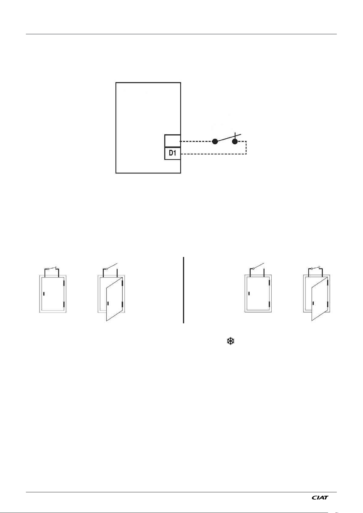
17 - CONNECTING THE FRAME CONTACT
Connecting the frame contact
● Parameter P16 or P17
Frame contact to be wired to input D1- ┴ or D2 ┴ depending on your device's configuration (refer to the corresponding wiring
diagram).
Regulator
Window switch
The cable used has a maximum length of 10 m, and minimum section of 0.9 mm². It is recommended to use a twisted and
shielded cable.
Note: the window switch must be insulated from earth. If there is shielding present, it must be connected to the comfort unit earth.
● Direction of window switch
(default)
● If the window is open and the controller has a display terminal, this will display " " instead of the temperature and the keys
will be locked.
Note:
- When the window re-closes, the unit restarts automatically
- The terminal display will return to "normal" after 10 seconds, the time it takes for it to synchronise with the controller
Note: for a Master/Slave loop, the window switches must be connected to the Master unit (all contacts in series, normally
closed).
NA 12.54 D EN - 18
Page 21
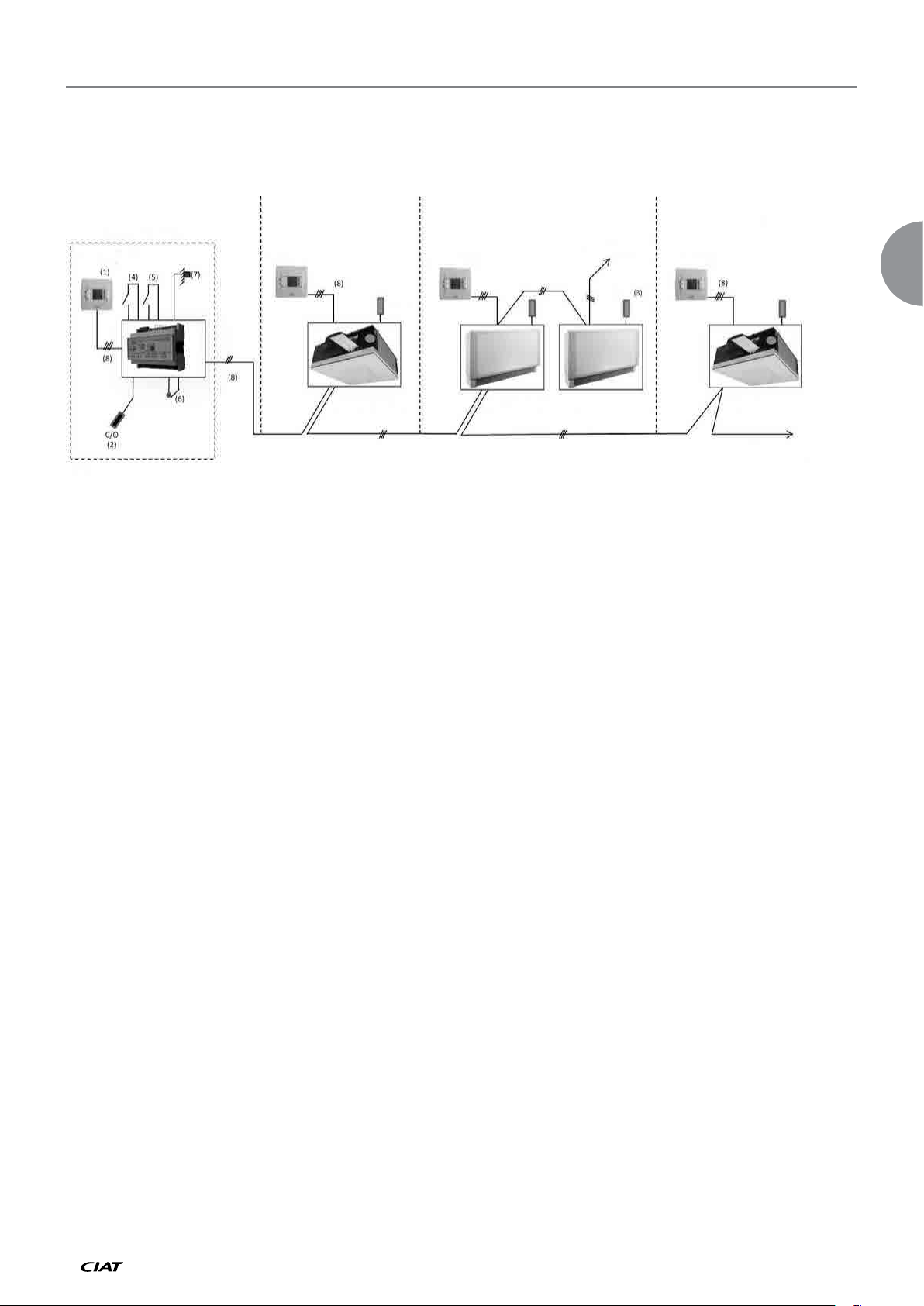
18 - CENTRALISED MANAGEMENT WITH V300
CIAT offers centralised management with the V300.
Management by centralised zone timer for comfort units.
Office 1 Office 2 Office 3Zone timer
Zone timer terminal
V300
controller
Electrical cabinet
V300 terminal V300 terminal
Sensor
V300 integrated
"Individual"
controller
"Master" controller
Sensor
V300 integrated
Sensor
V300 integrated
"Slave" controller
V300 terminal
Sensor
V300 integrated
"Individual" controller
To other offices/V300 Individual or
master controller (max. 30)
Maximum: 30 offices (corresponding to Master and/or individual units)
The comfort units (ductable, air handling units or cassettes), which are all independent, are equipped with V300 control.
Each comfort unit has its own comfort temperature sensor.
A centralised timer comprising a zone controller and a wired LCD terminal in an electrical cabinet outside the zone enable remote
centralised management of this loop. A terminal is connected to this controller for adjusting and operating the system.
The timer is integrated in this controller to ensure time management of the Comfort/Economy/Frost protection/Off modes.
. The terminal is used:
→ To set the integrated daily/weekly timer
→ To distribute all the comfort units across 6 self-contained zones
→ To determine, for each zone, the hourly management of the 4 modes (Comfort/Economy/Frost protection/Off)
→ To set, for each zone:
• The heating and cooling Comfort setpoints
• The heating and cooling Economy setpoints
• To override the time slots per zone, or for the entire building.
EN
. The "zone" controller therefore enables management of the entire building for:
→ The locally authorised setpoint shift range
→ Adjustment of the comfort restart time on the local wall-mounted terminal
→ Possible central changeover
→ Advance heating restart based on the outdoor temperature (depending on options)
Refer to manual No.14-13 for all possibilities and settings for the V300 zone timer.
EN - 19 N 12.54 D
Page 22
19 - ELECTRICAL CONNECTIONS - CABLE TYPES
Wall-mounted installation
Warning!
This unit must be installed in accordance with the connection diagram inside the housing. It must be installed in accordance
with accepted engineering standards and must conform with current local standards. In order to meet Class II requirements, the
corresponding installation instructions must be observed.
Mounting: on flush-mount box using the holes provided. Cables routed via the opening in the mounting plate.
Wiring:
- Remove the terminal's front panel
- Connect as per the unit diagram (see p 10)
Power supply
- 230/1/50 Hz or 230/1/60 Hz
Terminal/Controller connection
- Max. distance between the room terminal/Controller: 30 m.
→ Including the cable length required for the first slave, if applicable
- RS485 type wiring: 4 wires + shielding: 2 twisted pairs with shielding connected to the comfort unit earth (mandatory), see
"Master/Slave connection" characteristics
→ Pair 1: A+ and B-, polarity to be observed
→ Pair 2: 5V and
→ Shielding ┴ controller and terminal end
Master/Slaves connection
- 15 slaves max.
- Max. distance between the master and the 1st slave: 30m including cable length for room terminal
- Max. distance between 2 Slave controllers: 30 m
- Wiring:
→ RS485 type + 2 wires + shielding
→ Topology: controllers wired in series
→ Polarity to be observed
→ Flexible cable with 1 or 2 shielded twisted pairs with shielding continuity and shielding connected to the Master
comfort unit earth
→ Pair 1: A+ and B-, polarity to be observed
→ Pair 2: ┴ (if existing)
→ Shielding ┴ continuity between the Master and Slave controllers
→ Max. capacity between cables: 150 Cc/m
→ Filotex FMA-2P type cable, Belden ref. 9842/9842NH 24AWG or equivalent 2 shielded twisted pairs
┴
Window contact input
- Wiring: 2 x 1 mm2 shielded twisted with shielding connected to the comfort unit earth.
- To be cabled to the Master and/or individual units only
We recommend marking the cables between the Master/Slave and Slave/Slave (from-to) in preparation for maintenance or site
developments over time.
Site monitoring and maintenance:
For the purposes of site monitoring and maintenance over time, we recommend that you have the following information:
An installation plan for equipment in the building, with a bus diagram
(Master/Slave and Zone clock bus if included)
Marking of the Master devices and their slave per unit
The position of the room thermostats and the device connected to them.
A summary of the types of bus cables used and their length
The position of the zone clock in the building (if included)
Note: when using the CIAT after-sales service, all of the above information will be requested by CIAT Services technicians before
any work.
Entered contact of window
- Cabling: 2 x 1 mm2 twisted armored with connecting of the armor plating on the earth(ground) of the unity(unit) of comfort.
- To cable on the units Masters(Teachers) and/or individual only
NA 12.54 D EN - 20
Page 23
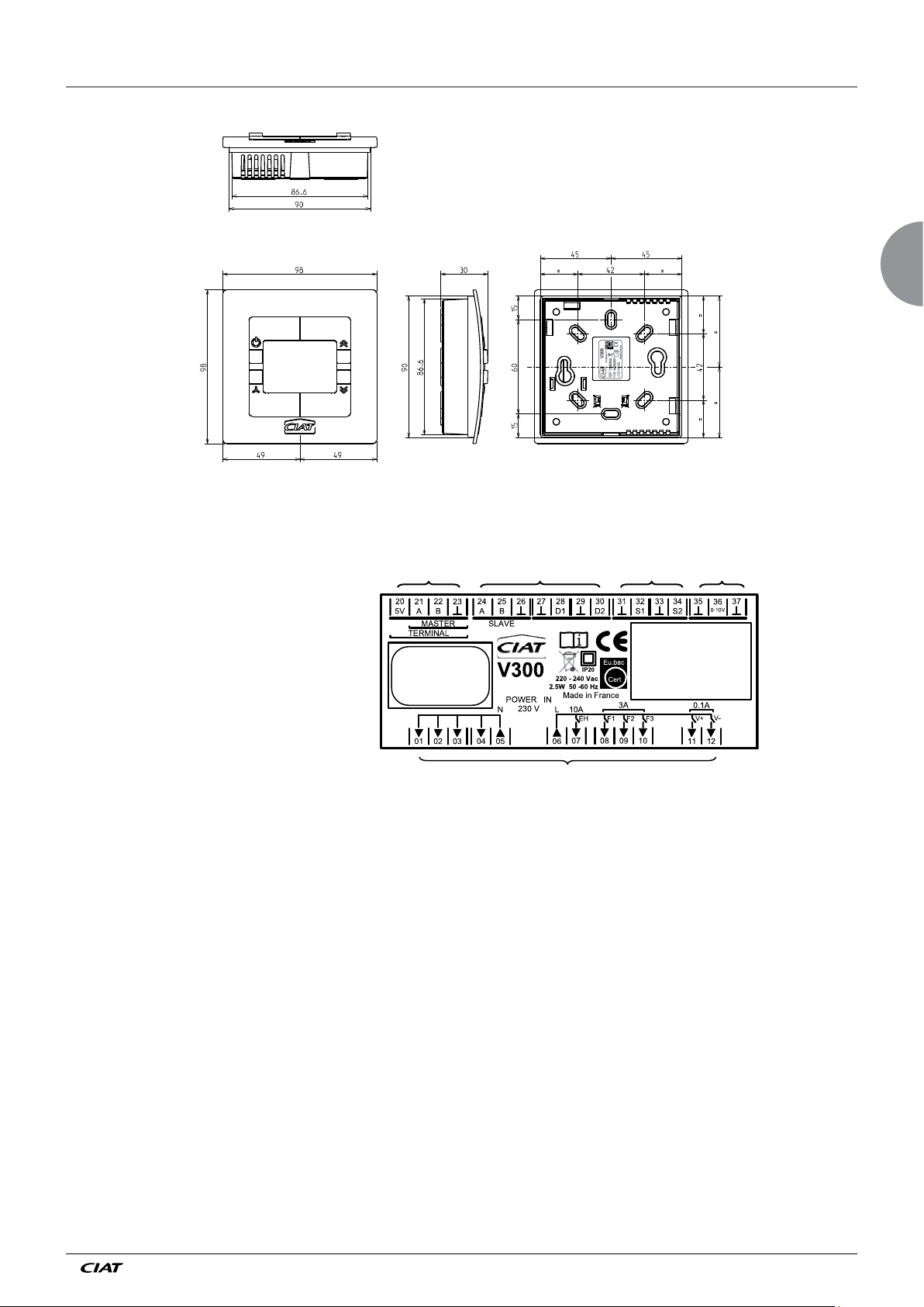
20 - TERMINAL DIMENSIONS
Wired wall-mounted and radio-frequency version
Colour RAL 9010
Controller wiring diagram
EN
Quick-release connector
REF : 7335301
FAB : 1625/0001
LOG : V2.0
Made in France - 2016
Screws
Screws
Male faston terminals
FAB: 1625 /0001 = Fabrication Year 2016/week no. 25/1st product manufactured in the week
2.8 x 0.8
Screws
EN - 21 N 12.54 D
Page 24
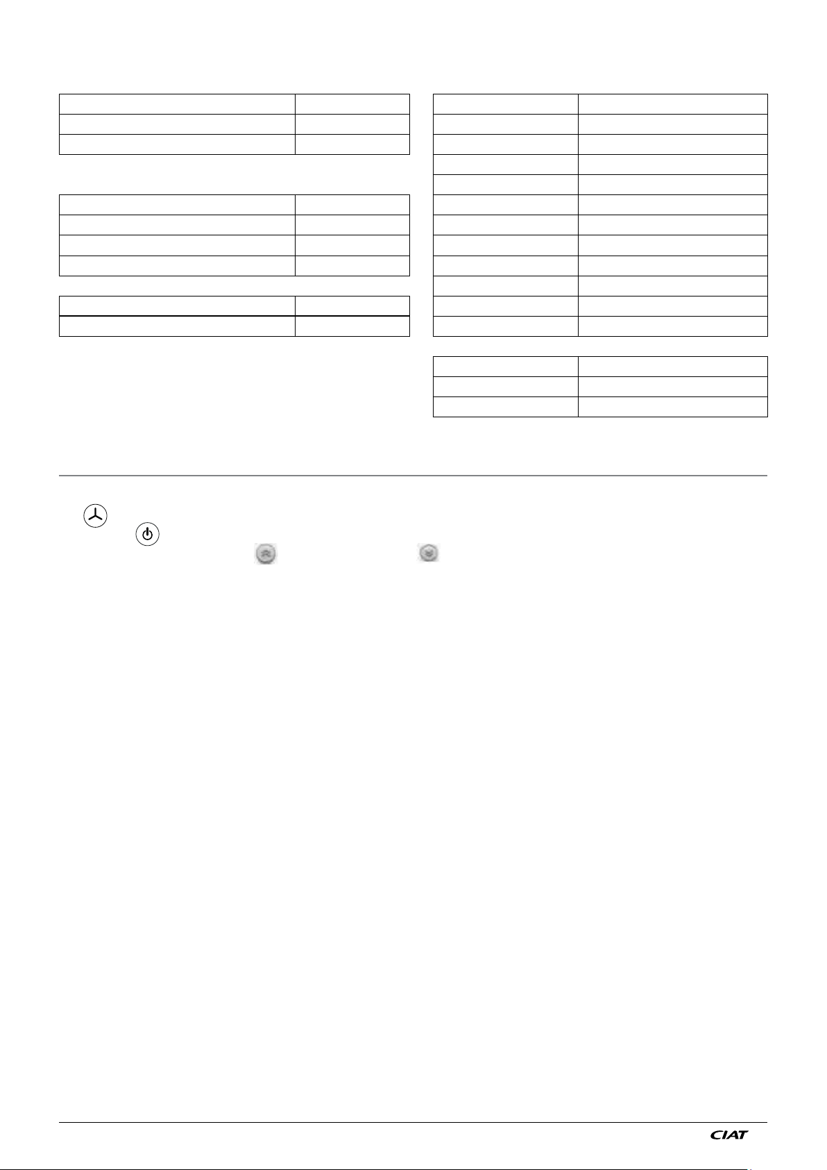
Technical caracteristics
Power supply Standards, directives
Supply voltage 220 - 240Vac 50/60 Hz Index of Protection IP 20 in accordance with EN 6059
Max. consumption 2.5W Insulation class Class II in accordance with EN 60335-1
Frost protection mode consumption 1.09W
Low voltage directive 2006/95/CE
Permitted ambient conditions EN 60335-1
Service temperature 0...45 °C EMC directive 2004/108/CE
Storage and transport temperature -20...65 °C EN 61000-6-1
Humidity 10 à 85 % HR EN 61000-6-3
sans condensation EUBAC EN 15500
Installation RoHS 2011/65/UE
Weight (kg) 0.315
Dimensions L x H x P (mm) 105 x 93 x 59
Additional information
Assembly instructions NA 12.53A V300
Default configuration FO300 parameter sheet
21 - USING THE USER TERMINALS
User procedure (for all systems):
The selector is used to select between Auto and Manual ventilation
Selecting the mode on the terminal switches the controller to frost protection mode (depending on the configuration).
To adjust the temperature, use the (higher temperature) or (lower temperature) keys
Setting range: + or - 4°C
"4-tube" and "2-tube cooling + electric" systems
HEATING and COOLING are automatic.
"2-tube cooling/heating automatic reversal" system
HEATING or COOLING depends on the water temperature.
"2-tube cooling only" system
The unit can only cool
"2-tube heating only" system
The unit can only heat.
"2-tube heating/cooling + electric" system
HEATING or COOLING depends on the water temperature.
- If the water is hot, the unit can heat.
- If the water is cold, the unit can heat and cool.
NA 12.54 D EN - 22
Page 25

Page 26
CIAT Service
www.ciat.fr
Registered address
Avenue Jean Falconnier B.P. 14
01350 Culoz - France
Tel. : +33 (0)4 79 42 42 42
Fax: +33 (0)4 79 42 42 10
[email protected] - www.ciat.com
Compagnie Industrielle
d’Applications Thermiques
Corporation with a capital of €26,728,480
R.C.S. Bourg-en-Bresse B 545.620.114
This document is not legally binding.
As part of its continuous drive to improve its equipment, CIAT reserves
the right to make any technical modifications without prior notice.
With Ecofolio,
all papers
can be recycled
 Loading...