

Page 1
Page 2
SAFETY
NOTICE
CAUTION
ALL SERVICE AND REBUILDING INSTRUCTIONS CONTAINED HEREIN ARE
APPLICABLE TO, AND FOR THE CONVENIENCE OF, THE AUTOMOTIVE
TRADE ONLY. All test and repair procedures on components or assemblies in
non-automotive applications should be repaired in accordance with instructions
supplied by the manufacturer of the total product.
Proper service and repair is
The service procedures recommended and described in
for professional
repair.
performance
special tools designed
recommended throughout this
Special attention should be exercised when working with spring or tension loaded
fasteners and devices such as E-Clips, Circlips, Snap rings, etc., as careless removal
may cause personal injury. Always wear safety goggles whenever working on
vehicles or vehicle components.
It is
These
possibility
It is important to note that these Cautions
procedures
not possibly know,
service
Motors
uses a service procedure, or
oneself
the service
Following these procedures will help assure efficient
important to
should be
that, improper service
Chrysler Motors
may *be performed, or of
has
not
thoroughly that neither
servlTe
and service
note
carefully
evaluate, and advise
undertaken any such broad
methods
they select.
important to the safe, reliable, operation of
this publication
personnel
reliability. Some of these
for specific
that
this
publication contains
read in order to
has
tool, that is not
and are
procedures.
publication.
minimize the
methods may
encountered
the service
the possible
recommended in
personal
safety,
effective
These
damage
and
Warnings cover only the situations
and recommended.
hazards of each.
service
methods
service procedures
special tools should
various
risk of personal
the vehicle or
trade of all
review.
nor
vehicle safety, be jeopardized by
all
motor
were developed
for performing vehicle
economical vehicle
require the
be
used when
Cautions
Chrysler Motors
conceivable
Consequently, Chrysler
Accordingly, anyone
this publication,
and
Warnings.
injury, or
render
it
ways that
must assure
vehicles.
use
of
the
unsafe.
and
could
who
7
WE SrjPPORT
VOLUNTARY TECHNICIAN
CERTIFICATION
THROUGH
Page 3
TALON
GROUP INDEX
ROSA.
-
-
BACKUP
TECHNICAL
INFORMATION
MANUAL
FOREWORD
This manual has been prepared as an introduction to
the specifications, features, construction and functions of the newly developed TALON. Please read
this manual carefully as it will be of assistance for
service and sales activities
Please note that the service manuals are also
available and should be used in conjunction with this
manual.
All information, illustrations and product descrip-
tions contained in this manual are current as at the
time of publication. We, however, reserve the right
to make changes at any time without prior notice or
obligation.
General. . . . . . . . . . . . . . . . . . . . . . . . . . . . .
Front Suspension
Rear Axle
............................................
Brakes - Eir$rii
Clutch
Cooling
Electrical
Engine
Intake
Fuel
. . . . . . . . . . . . . . . . . . . . . . . . . . . . . . . . . . . . . . . . . . . . . . . . . . . .
. . . . . . :. . . . .
. . . . . . . . . . . . . . . . . . . . . . . . . . . ..-..................
....................................................
and Exhaust
System
................................
.
. . . . . . . . . . . . . . . . . . . . . . . . . . ..s...
. . . . . . . . . . . . . . . . . . . . . . . . . . . . . . . . . . . .
............................
. . . . . . . . . . . . . . . . . . . . . . . . . . . . . . . . . . . . . . . .
. . . . . . . . . . . . . . . . . .
.
This
BACKUP DSM manual IS to be used ONLY as a BACKUP. Please DO NOT REDISTRIBUTE
WHOLE SECTIONS.
a GENUINE DSM MANUAL. It CANNOT BE considered a REPLACEMENT (Unless
manual was lost or destroyed.)
Please See
Chrysler Motors reserves the right to make changes in design or to
make additions to or improvements in its products without
any obligations upon itself to install them on its products
manufactured.
a *-a- .I._.
This
BACKUP was sold to you under the fact that you do
README.N
or for
Thank you. Gimmiemymanual@hotmail.com
.-1-L,.*
_____ #Q
additional information
^_^__
l L.-
indeed
your
Orintul
OWN
original
imposing
PreViOUSlV
in U.S.A.
Propeller
Shaft
and
Universal
Joint
Rear Suspension
Power
Transaxle - Automatic
Body
Heaters
steering
Manual
....................................................
and Air Conditioning
Emission Control
. . . . . . . . . . . . . . . . . . . . . . . . . . . . . . . .
....................................
Systems
. . . . . . . .
....................
........
............
l
m
l
CD
m
m
A
RI
Page 4
._._ -_-
1
-.
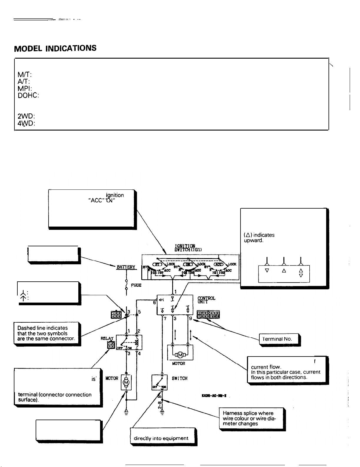
MODEL
INDICATIONS
The following abbreviations are used in this manual for classification of model types.
M/T:
A/T:
Indicates the manual transaxle, or models equipped ‘with the manual transaxle.
Indicates the automatic transaxle, or models equipped with the automatic transaxle.
MPI: Indicates the multi-point injection, or engines equipped with the multi-point injection.
DOHC:
Turbo:
Non-Turbo:
Indicates an engine with the double overhead camshaft, or a model equipped with such an engine,
Indicates an engine with turbocharger, or a model equipped with such an engine.
Indicates an engine without turbocharger, or a model equipped with such an engine.
2WD: Indicates the front wheel-drive vehicles.
4WD: Indicates the 4 wheel-drive vehicles.
HOW TO READ A CIRCUIT DIAGRAM
Circuit diagrams are prepared as follows using these
symbols:
The current flow at the inition
key positions “ACC” ” N” and
“ST” is shown combined.
Be sure to trace the appropriate
circuit depending on the ignition
key position.
1
Indicates power
supply connection.
1
8
~
NOTE
For specific details concerning the interpretation of
circuit diagrams, refer to the separately bound
Service Manual.
These symbols show the input to
and output from (direction of
current flow to and from) an
electronic control unit.
o&ficates
that current flows
Input Output output
Input
and
Connectors
A :
Female connector
9.1
Male connector
This symbol indicates connector
for equipment (male connector
used as an intermediate connector) viewed from in front of the
Connector for equipment with attached harness
is..
\
I
l-4’
Arrowindicates direction of
Connector inserted
Page 5
-
GENERAL
CONTENTS
--- -~- -------l
O-l
GENERAL DATA AND SPECIFICATIONS . . . . . . . .
TECHNICAL FEATURES
4WD
(Four-wheel Drive)
PJT
Safety-lock System
Basic Construction
Engine
Exterior
Interior
Theft-alarm System (Option for 4WD
Vehicles)
................................................................
................................................................
. . . . . . . . . . . . . . . . . . . . . . . . . . . . .
. . . . . . . . . . . . . . . . . . . . . . . . .
....................................
........................................
........................................
............................................
..__...............................
.._._........_.....................
13
VEHICLE IDENTIFICATION
2
7
7
4
5
2
3
8
Engine Model Stamping
Vehicle Identification Code Chart Plate
Vehicle Identification Number List
Vehicle Identification Number Location
Vehicle Information Code Plate
Vehicle Safety Certification Label
.._..................._........_
....................................
........
................
........
........................
....................
9
12
9
10
9
1 1
12
Page 6
o-2
GENERAL
- Technical Features
TECHNICAL FEATURES
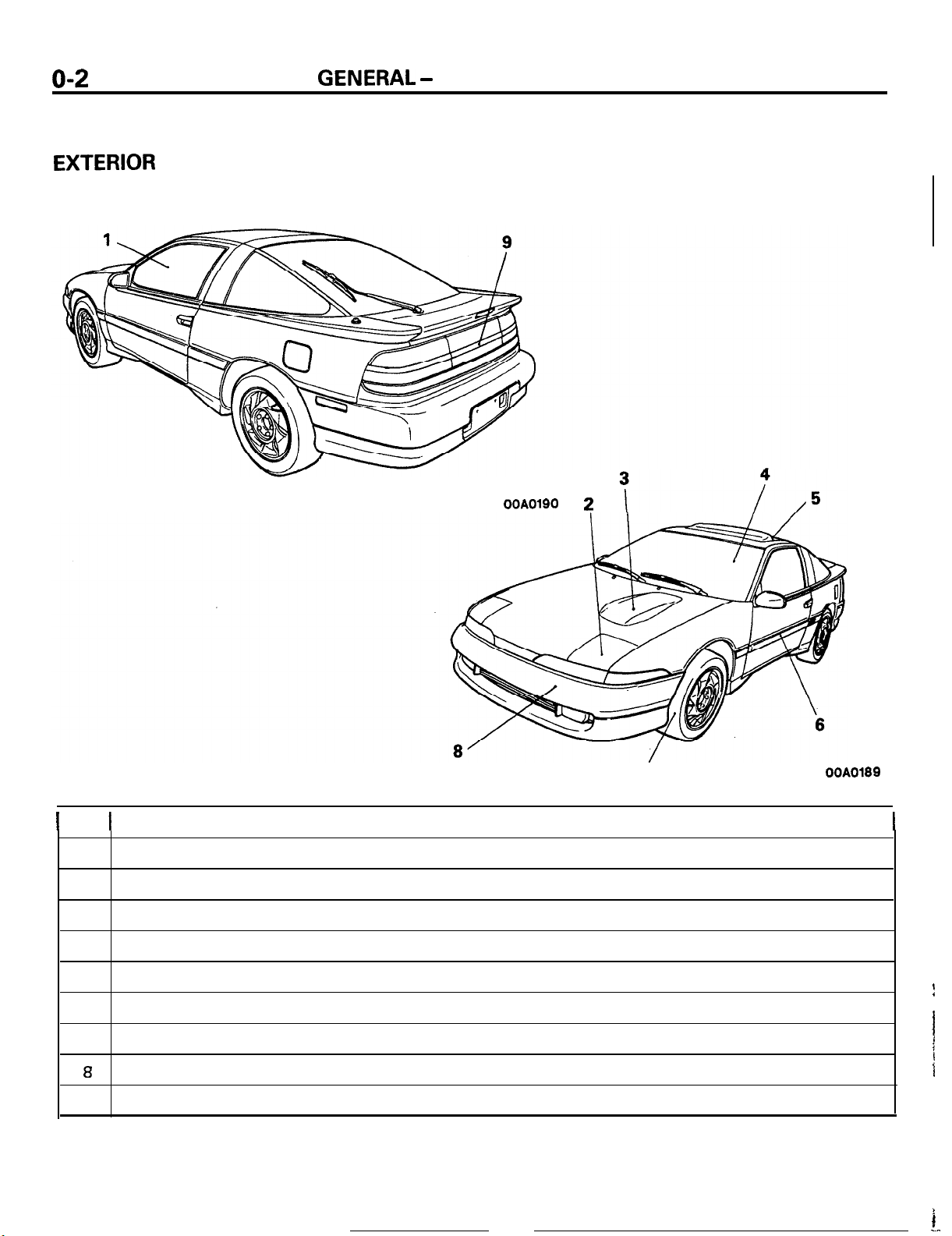
EXTERIOR
Low and wide profile for appearance sports car
impression.
ROOCAAB
OOA0190 2
1
No.
1
2
3
4
5
6
7
a
9
7
t
Flush surface and low front high rear styling for outstanding aerodynamic performance
Pop up headlights of optical horn type
Hood bulge indicating DOHC engine
Futuristic glass upper body
Removable tilt up sunroof (option for all models)
Smooth integrated body lines giving a lean appearance
Wide tires and wide tread to emphasize power and stability
Bumpers made integral with the body
Wall to wall tail lamps for sporty image
Features
OOA0189
I
I
f
I
1
i
I
i
--
Page 7
Y
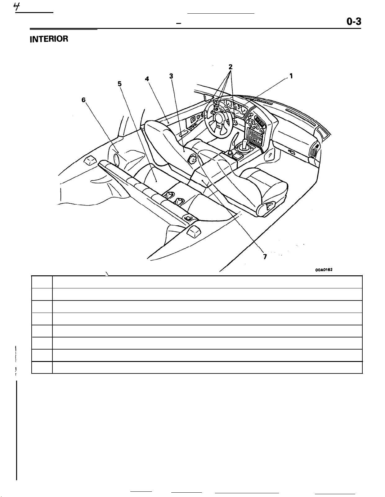
INTERIOR
GENERAL - Technical Features
o-3
\
No.
1
Cock pit type instrument panel to give sporty image
2
Switches arranged around the driver seat for easy access and operation
3
Hi back seats with integral head rest for comfortable and firm holding
4
Integrally molded door trims with round and smooth transition to the instrument panel
,
I
i
!
!
I
5
Sporty double seat with firm holding
6
Rear quarter trims with built in dynamic speakers
7
Easy to use large capacity console box
Features
/
OOAO162
Page 8
o-4
GENERAL
- Technical Features
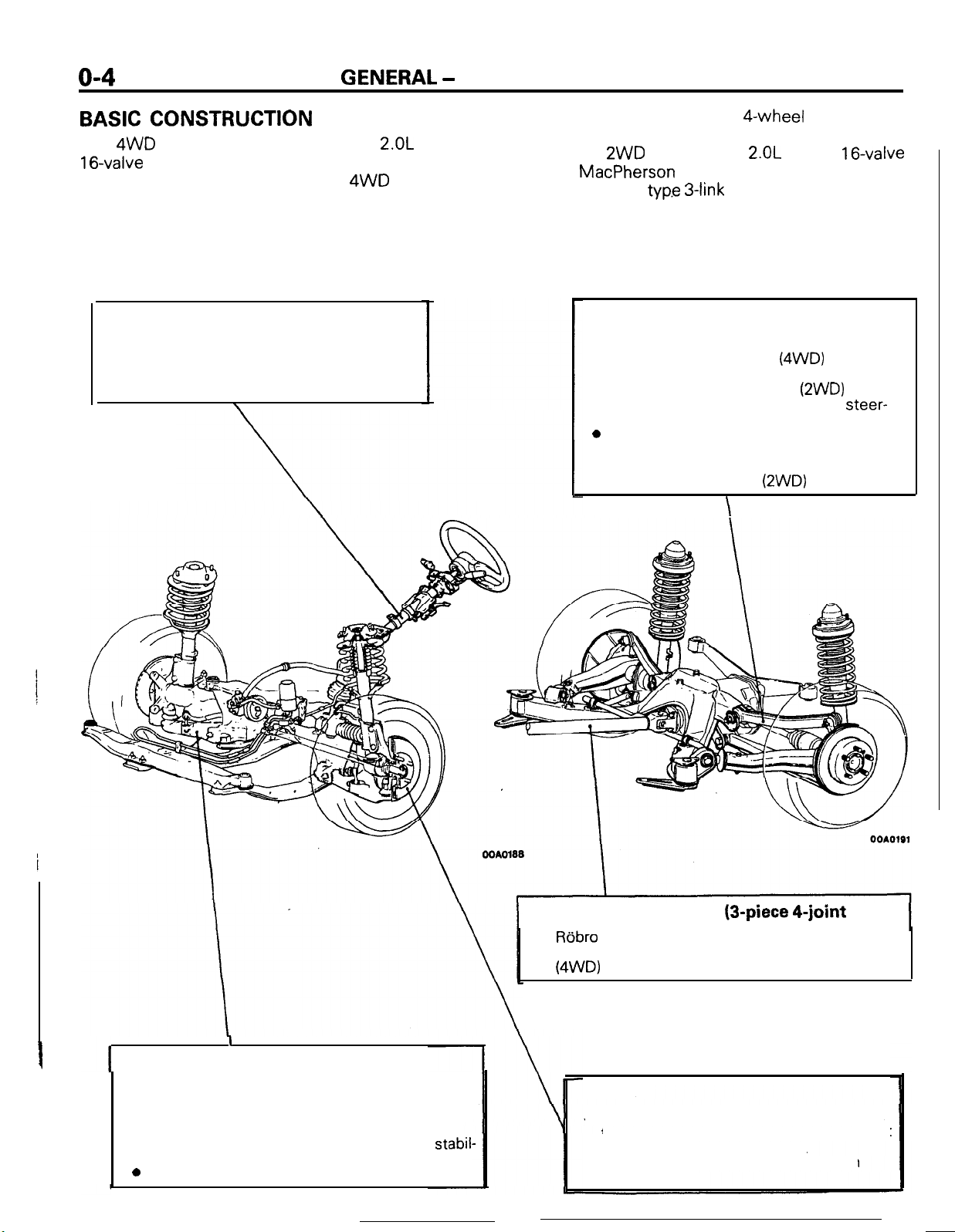
BASIC
The 4WD vehicles are equipped with
16-valve
CONSTRUCTION
2.OL
DOHC
turbocharged engine and incorporate new
technologies such as full time 4WD of center
differential type with viscous coupling differential
limiting for excellent running stability and excellent
Steering
l Light weight and compact rack and pinion
type for high steering response
l Tilt steering mechanism to give optimum
driving position
\
driving across bad roads, and $-wheel independent
suspension for comfortable riding.
Adopted on
2WD
vehicles are
2.OL
DOHC
16-valve
engine, MacPherson strut type front suspension
and torsion axle
typ.e 3-link
rear suspension.
Rear suspension
l Self-aligning double wishbone type suspen-
sion for comfortable ride
l Torsion axle type 3 link suspension for
outstanding driving stability
l Negative chamber for outstanding steer-
ability during high speed driving
0
Anti-lift geometry for high stability during
braking
l
Integral torsional bar type axle beam for
optimum roll stiffness
\
(4WD)
(2WD)
(2WD)
I
Front suspension
The front suspension of McPherson strut type
independent suspension system
l Under steer geometry for outstanding steering
stability
l Negative offset geometry for outstanding
ity at braking
0
Offset coil springs for comfortable ride
stabil-
Front propeller shaft (3-piece
l
Robro
joint to absorb lengthwise and angular
change and prevent transmission of vibrations.
(4WD)
4-joint
Brakes
l
Cross piping dual type proportioning
that keeps balanced braking power even at
failure of the hydraulic system.
l Four wheel disc brake system for high
braking power.
type)
valve
Page 9
GENERAL
- Technical Features
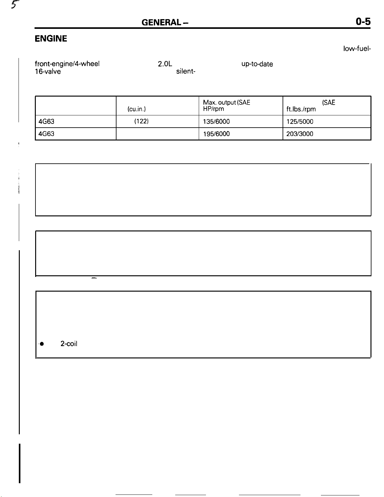
ENGINE
The engines are the transverse-mounted engine
especially for front-engine/front-wheeldrive or
front-engine/4-wheel drive models, the
16-valve
engine with high-performance, silent-
SPECIFICATIONS
2.OL
DOHC
o-5
operation,
low-vibration,
consumption features, an engine that fully displays
the most
up-todate
engine technology.
low-noise, low-fuel-
Engine model
4G63
Non-Turbo 1997
4663
Turbo
Displacement
cc
(cu.in.1
(122)
1997 (122)
h$xo$put (SAE
135/6000 125/5000
195/6000
net)
Max. torque
ft.Ibs./rpm
203/3000
(SAE
net)
FEATURES
High performance and low fuel consumption
l The rocker arm reduces the valve-actuation torque as well as fuel consumption.
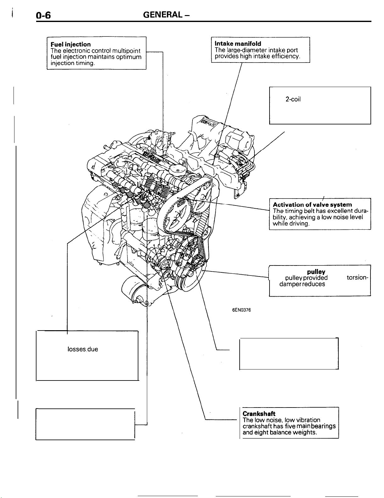
l Air-intake efficiency improved through the adoption of the optimum air-intake system layout.
l Improved response and fuel consumption has been achieved by electronic control multipoint
fuel injection.
l Water-cooled turbocharger. <Turbo>
Quiet operation
l Noise and vibration have been decreased by the adoption of roller rocker arms.
l Noise generated by the valve mechanism has been decreased by the hydraulic auto lash adjusters.
l Vibrations have been decreased by the adoption of bearing caps with beams which increase the
rigidity of the crankshaft support points.
-
Serviceability
l Complete self-diagnosis functions.
l Enhanced reliability through the adoption of gold-plated connector terminals.
l Use of an auto tensioner achieves maintenance-free, automatic adjustment of timing belt
tension.
l Use of the auto lash adjusters achieves maintenance-free, automatic adjustment of valve clearance
.o
The
2coil
ignition system without a distributor supplies sufficient ignition energy even during
high speed operation.
Page 10
O-6
GENERAL
- Technical Features
Ignition system
The
2coil
a distributor supplies sufficient
ignition energy even in the high
speed operation.
ignition system without
Valve mechanism
l
The roller rocker arms decrease
the valve system.
l
The auto lash adjusters eliminate the need to adjust the valve
clearance.
losses.due
to friction in
Combustion chamber
The combustion chamber is provided with a squish area for high
combustion efficiency.
76-4
EN0376
Crankshaft
The
oullev orovrded
al
da’mper
sion of vibrations.
ieduces the transmis-
pu!ley
with a torsion-
Auto tensioner
The auto tensioner eliminates the
need to adjust the timing belt
tension.
I
J
t
]I
crankshaft has five
marn
bearings
Page 11
GENERAL -
Technical Features
o-7
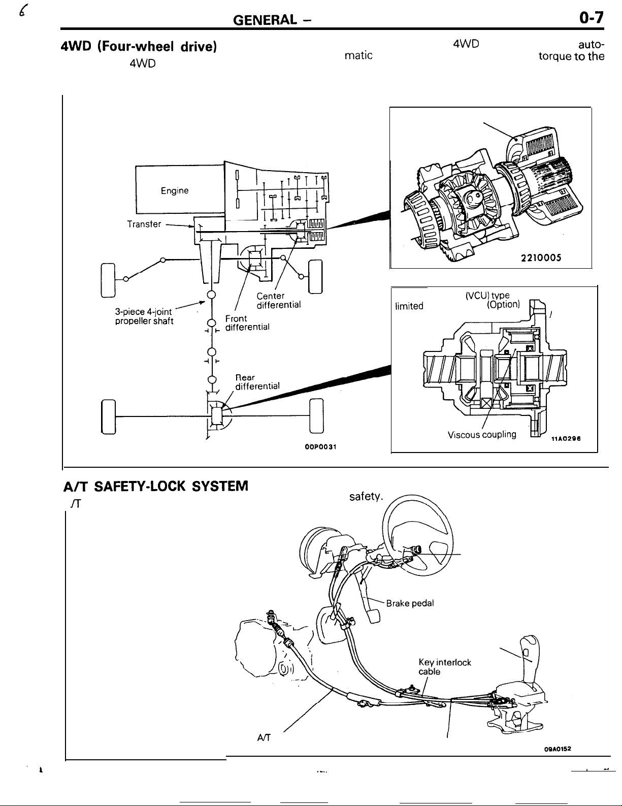
4WD
The full time 4WD system adopts viscous coupling
unit (VCU) as the differential limiting device for the
(Four-wheel drive)
Engine
r_
center differential of 4WD vehicle to achieve
matic
and ideal distribution of engine torque
front and rear wheels.
Viscous coupling
Viscous coupling
limited
slip differential
(VCU)
(OptIOn)
VP?
auto-
to
the
A/T
SAFETY-LOCK
JT
safety-lock system (shift lock device and key
SYSTEM
AIT
control cable
00P0031
interlock device) has been adopted to improve
Key interlock device
safety*FN
Ignition key cylinder
Shift lock device
Selector handle
Shift lock cable
._...
~ ^.
Page 12
O-8
GENERAL
- Technical Features
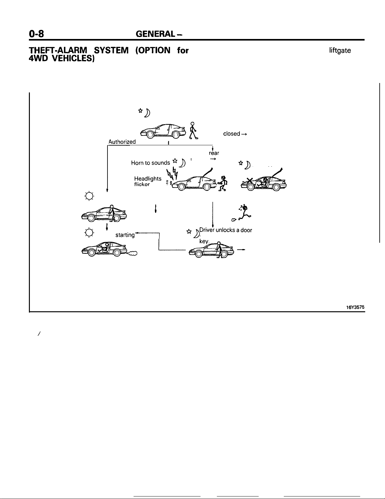
THEFT-ALARM SYSTEM (OPTION for
4WD
To make the vehicle theftproof, this system is so
designed that the headlights go on and off and the
horn is sounded intermittently for ‘about three
VEHICLES)
a-tDriver opens door with the key
4uthorized
I
Unauthorized
1
SYSTEM DISARMED
0
1
Normal
starting-1
minutes when the locked door, hood or liftgate has
been forced open without using a key.
Furthermore, the starter circuit is interrupted so that
the engine may not be operated, making the vehicle
theftproof.
About 20 seconds after all doors are closed
and locked, the rear hatch is closed, and the
hood is closed---t SYSTEM ARMED
A door, rf!ar hatch or hood is broken
to open + ALARM
I
ACTIVATED
Engine
is disabled to start.
I
or
rear hatch with the
-
ALARM DEACTIVATED
(SYSTEM DISARMED)
16Y3575
/
Page 13
GENERAL
-
Vehicle Identification
019
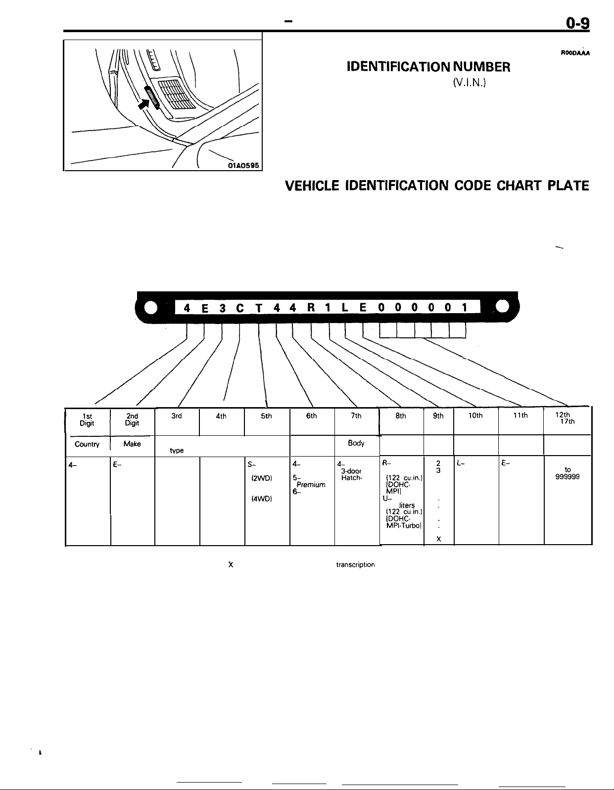
VEHICLE IDENTIFICATION
VEHICLE IDENTIFICATION
The vehicle identification number
NUMBER
(V.I.N.)
LOCATION
is located on a plate
RooDAiA
attached to the left top side of the instrument panel.
VEHICLE
IDENTIFICATION
CODE CHART PLATE
All vehicle identification numbers contain 17 digits. The vehicle
number is a code which tells country, make, vehicle type, etc.
/
3rd
Digit
Vehicle
3- 6-
Passenger
car
tvw
I
C-
4th
Digit
Others
Manual
seat belt
Automatic
seat belt
E-
Eagle
2nd
Digit
Make
1st
Digit
Country
---l--
1
I-
USA
NOTE
l “Check digit” means a single number or letter
I
X
used to verify the accuracy of
I
S-
Talon
IZWDI
T-
Talon
(4WD)
I
5th
Digit
Line
Digit
Price
class
4- 4-
High
6-
Premrum back
6
Special
6th
\
\
7th
Digit
Sody
Bdoor
Hatch-
transcriptron
6th
Digit
Engine
R-
2.0 liters 1990
/;gHE.in.)
MPI]
U-
2.0
liters
/;gHF.in.)
MPI-Turbo]
of vehicle identification number.
9th
Digit
*Check
digits
1
:
1
:
9
X
10th
Digit
Model
year
L- E-
year
Digit
Plant
DSM
11th
12th
to
17th
Digits
Serial
number
000001
99%99
Page 14
r -.--
O-10
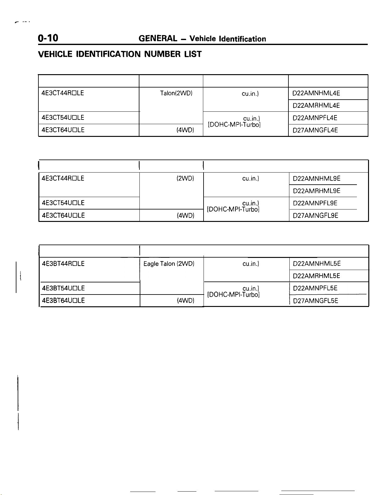
VEHICLE IDENTIFICATION
GENERAL - Vehicle Identification
NUMBER
LIST
VEHICLES FOR FEDERAL
V.I.N. (except sequence number)
4E3CT44RClLE
4E3CT54UClLE
4E3CT64UOLE
Brand
Eagle TalonQWD)
Eagle Talon
(4WD)
Engine displacement
2.0 liter (122 cu,in.)
[DOHC-MPI]
2.0 liter (122 cu.in.)
[DOHC-MPI-Turbo]
VEHICLES FOR CALIFORNIA (Can also be sold in Federal States.)
1
V.I.N. (except sequence number)( Brand
4E3CT44tKILE
4E3CT54UOLE
4E3CT64UOLE
Eagle Talon
Eagle Talon
(2WD)
(4WD)
1
Engine displacement
2.0 liter (122 cu.in.)
[DOHC-MPI]
2.0 liter (122
[DOHC-MPI-Turbo]
cu.in.1
Models Code
D22AMNHML4E
D22AMRHML4E
D22AMNPFL4E
D27AMNGFL4E
Models Code
I
D22AMNHMLSE
D22AMRHMLSE
D22AMNPFLSE
D27AMNGFLSE
VEHICLES FOR CANADA
1
V.I.N. (except sequence number)1 Brand
4E3BT44ROLE
4E3BT54UOLE
4E3BT64UOLE
Eagle Talon
(4WD)
Engine displacement
2.0 liter (122 cu.in.)
[DOHC-MPI]
2.0 liter (122 cu.in.)
[DOHC-MPI-Turbo]
Models Code
D22AMNHML5E
D22AMRHML5E
Page 15
GENERAL
-
Vehicle Identification
o-11
/lb------
HODEL
ENGINE
TNANS
coLoK E
I
OOAO163
OOAO164
3
4
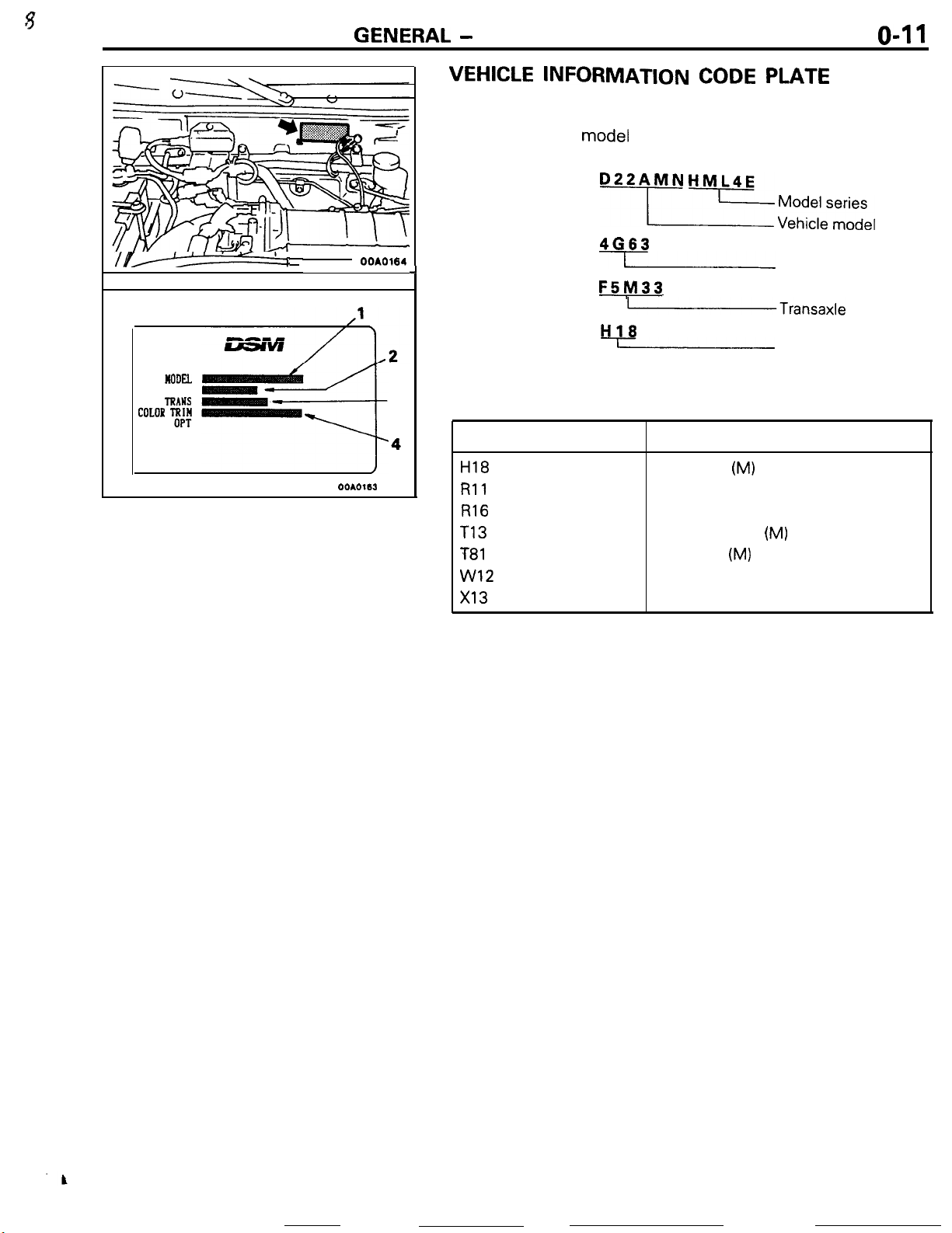
VEHlCLE
Vehicle information code plate
the engine compartment.
The plate shows
and body color code.
1. MODEL
2. ENGINE
J
3. TRANSAXLE
4. COLOR,
TRIM OPT
INFORMATION
model
BODY COLOR CODE
Exterior code
H18
Rll
R16
T13
T-81
w12
x13
CODE PLATE
is riveted onto the bulkhead in
code. engine model, transaxle model,
SF
4663
I
F5!Vl33
(Transaxle
H18
)
Body color
Light Gray
Red
Dark-Red
Turquoise Blue
Dark Blue
White
Black
bll~~l~~~e,
Engine model
Monotone exterior
color code
(M)
(M)
(M)
model
Page 16
o-12
GENERAL
- Vehicle Identification
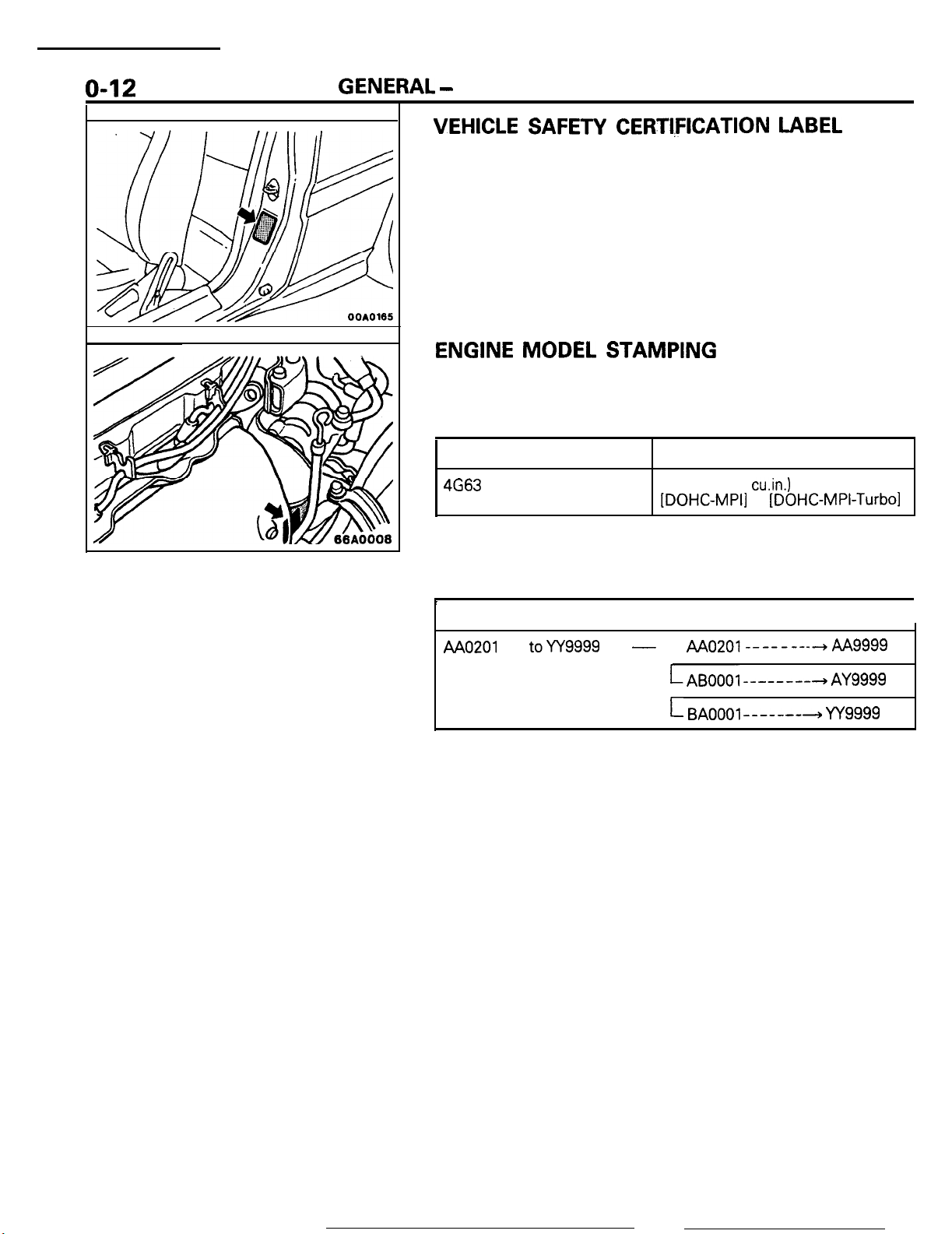
VEHICLE SAFETY CERTI,FICATION LABEL
1.
The vehicle safety certification label is attached to the face
of left door pillar.
2. This label indicates the month and year of manufacture,
Gross Vehicle Weight Rating (G.V.W.R.), Gross Axle Weight
Rating (G.A.W.R.) front, rear and Vehicle identification
Number (V.I.N.).
ENGINE MODEL
1. The engine model number is stamped at the front side on
the top edge of the cylinder block as shown in the
following.
Engine model
4663
2. The engine serial number is stamped near the engine
model number, and the serial number cycles, as shown
below.
Engine serial number
AA0201
toYY9999
STAMPING
Engine displacement
2.0
liter (122
[DOHC-MPI]
Number cycling
-
AAo201--------hAA
LAB0001
L BAOOOl-------+ YY9999
cu.in.)
or
[DOHC-MPI-Turbo1
--------+
AY9999
Page 17
GENERAL - General Data and Specifications
o-13
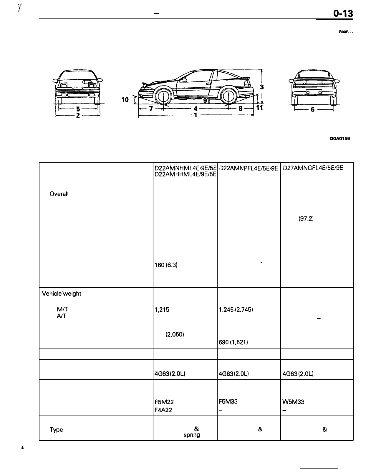
GENERAL DATA AND SPECIFICATIONS
Items
Vehicle dimensions
Overall
Overall width
Overall height
Wheel base
Tread
Overhang
Minimum running ground
clearance
Angle of approach
Angle of departure
length
mm (in.)
Front
Rear
Front
Rear
.
1
4,330 (170.5)
2
1,690 (66.5)
3
1,306 (51.4)
4 2,470 (97.2)
5
1,465 (57.7)
6
1,450 (57.1)
7
950 (37.4)
8
910 (35.8)
9
lsO(6.3)
10 16.5”
11 19”
4,350 (171.3) 4,380 (172.4)
1,700 (66.9)
1,306 (51.4)
2,470 (97.2)
1,465 (57.7)
‘1,450 (57.1)
960 (37.8) 960 (37.8)
920 (36.2) 950 (37.4)
160 (6.3)
13.8”
17”
’
1,700 (66.9)
1,321 (52.0)
2,470
(97.2)
1,465 (57.7)
1,455 (57.3)
158 (6.2)
1’4.7”
18.4”
M...
OOAO159
Vehicle’weight kg (Ibs.)
Curb weights
M/T
Al-r
Gross vehicle
Gross axle weight rating
Seating capacity
Engine
Model No.
Transaxle
Model No.
Manual transaxle
Automatic transaxle
Clutch
Type
weight
rating
1,215 (2,679)
1,240 (2,734)
1,620 (3,571)
Front 930
Rear
690 (1,521)
4
4663 (2.OL)
F5M22
F4A22
Dry-single disc &
diaphragm spnng
(2.050)
1.245.(2,745)
1,620 (3,571) 1,782 (3,929)
930 (2,050)
690(1,521)
4
4663
(2.OL)
F5M33
-
Dry-single disc
diaphragm spring
&
1,245 (2,745)
979 (2,158)
803 (1,770)
4
4663 (2.OL)
W5M33
-
Dry-single disc &
diaphragm spring
-
Page 18
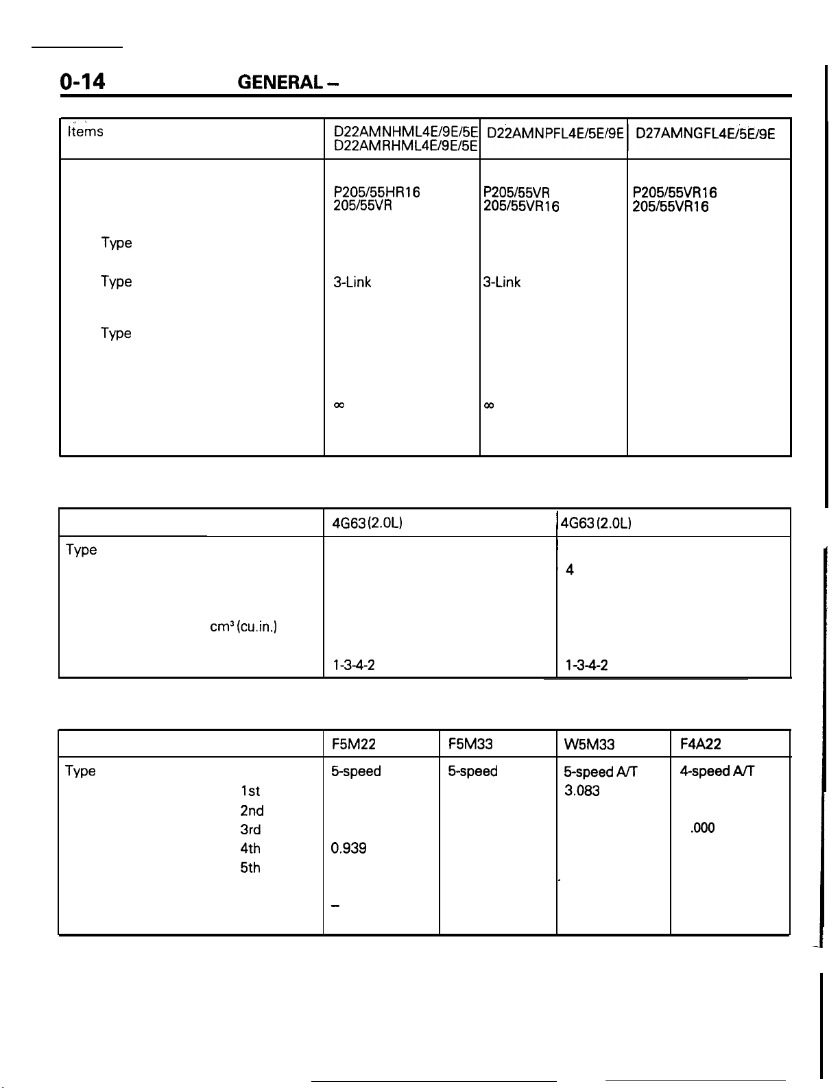
o-14
tiems
Chassis
Tire
Front suspension
Type
Rear suspension
Type
Brake
Type
Steering
Gear type
Gear ratio
Fuel tank
Capacity liters (gals.)
GENERAL
Front
Rear
- General Data and Specifications
P205/55HR16
205l55VR 16
Independent strut
3-Link
Torsion axle
Disc
Disc
Rack and pinion
m
60 (16)
or
P205/55VR
205155VR16
Independent strut
3-Link
Torsion axle
Disc
Disc
Rack and pinion
00
60 (16)
16 or
P205155VR16
205155VR16
Independent strut
Double wishbone
Disc
Disc
Rack and pinion
co
60 (16)
or
ENGINE SPECIFICATIONS
Items
Type
Number of cylinders
Bore
Stroke
Piston displacement
Compression ratio
Firing order
mm (in.)
mm (in.)
cm3 (cu.in.)
TRANSAXLE SPECIFICATIONS
Items
Type
Gear ratio
Transfer ratio
Final drive ratio
gear
gear
1st
2nd
3rd
4th
5th
Reverse
4G63
(2.OL)
Non-Turbo
In-line DOHC
4
85.0 (3.35)
88.0 (3.46)
1,997 (122)
9.0
l-3-4-2
F5M22 F5M33
5-speed
3.363
1.947
1.285
0.939
0.756
3.083
-
3.941
M/T
5-speed
3.038
1.833
1.217
0.888
0.741
3.166
3.437
M/T
1 4663 (2.OL)
~ In-line DOHC
‘4
85.0 (3.35)
88.0 (3.46)
1,997 (122)
7.8
l-3-4-2
W5M33
&speed
3.083
1.684
1.115
0.833
0.666
’
3.166
1.090
3.866
ArF
Turbo
F4A22
4-speed AiT
2.846
1.581
1
.ooo
0.686
2.176
3.562
Page 19
it?
2-1
FRONT
SUSPENSION
CONTENTS
ANTI-DIVE
FRONT AXLE
Drive Shaft
Hub and
GENERAL INFORMATlON
Construction Diagram
Specifications
GEOMETRY
........................................................
........................................................
Knuckle
................................................
.....................................................
....................................
................................
........................................
5
8
8
9
2
2
3
LOWER
NEGATIVE-OFFSET GEOMETRY
OFFSET SPRING
STABILIZER
ARM
........................................................
................................................
............................................................
no2&--
....................
7
5
6
7
Page 20
2-2
FRONT
SUSPENSION
GENERAL INFORMATION
-
General Information
The front suspension has a simple construction, the
McPherson strut type independent suspension
featuring light unsprung weight.
The front Suspension has the following features:
l Excellent driving stability, thanks to the
“antidive” geometry.
.
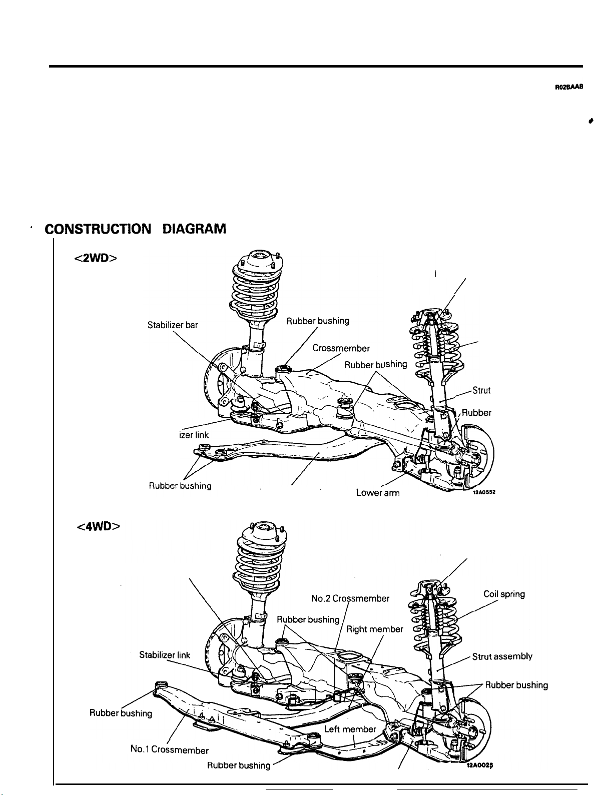
CONSTRUCTION DIAGRAM
<2WD>
l Excellent braking stability, thanks to the
negative-offset geometry.
l Greatly improved riding comfort, thanks to the
offset arrangement of the coil springs.
Rubber insulator
/
Coil spring
lshing
,Strut
assembly
t
<4WD>
Stabili
Stabilizer bar
Centermember
Lowecarm
I ,Rubber
Rubber insulator
bushing
No.1 Crokmember
Lower arm
- -
12AOO25
Page 21
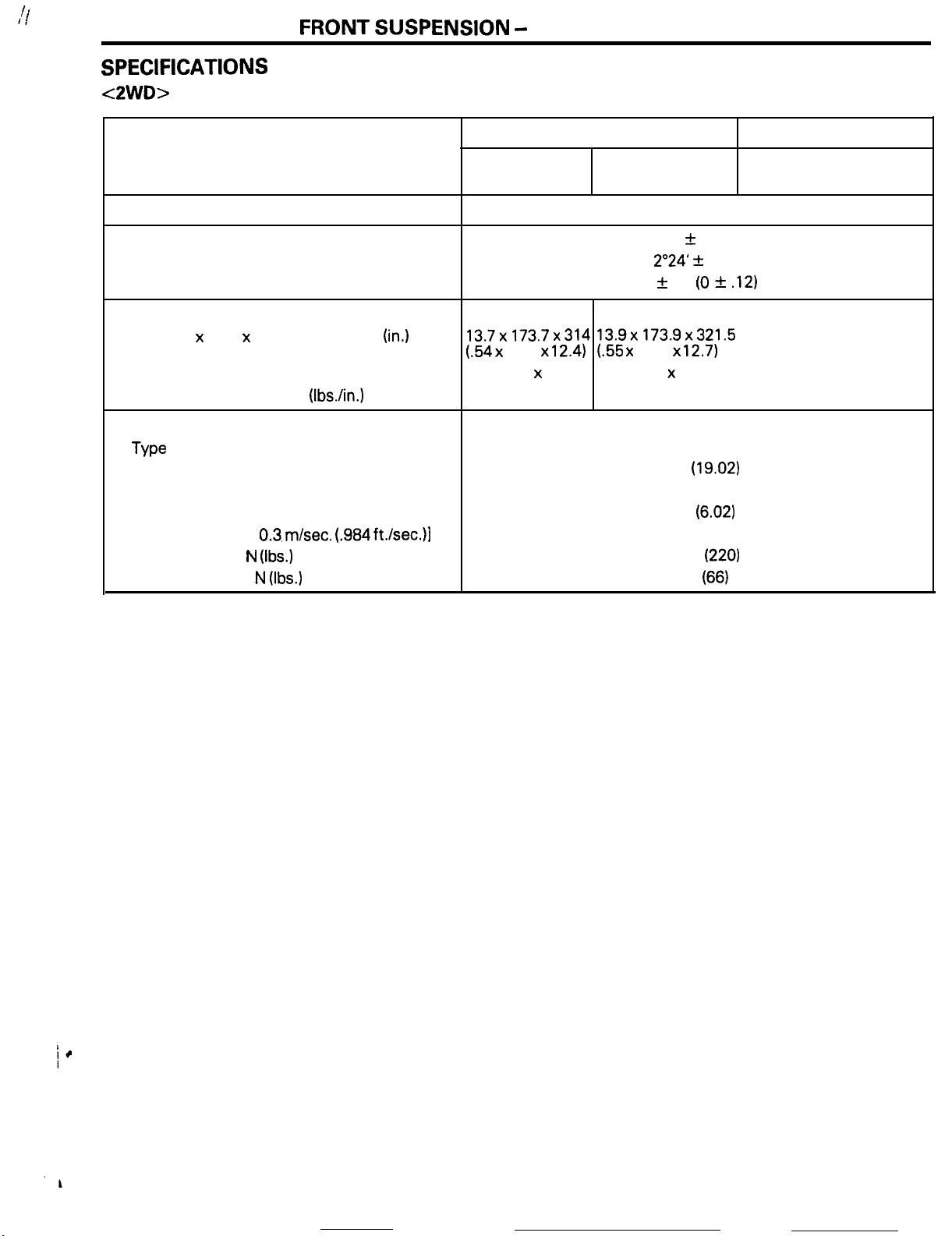
SPECIFICATIONS
<2WD>
FRONT
SUSPENSION
-
General Information
2-3
terns
Suspension system
Camber
Caster
Toe-in
Coil spring
Shock absorber
mm (in.)
Wire dia. x O.D. x free length
Coil spring identification color
Spring constant N/mm (IbsAn.)
Type
Max. length
Min. length.
Stroke
Damping force [at
Expansion N
Contraction N
mm (in.)
mm (in.)
mm (in.)
0.3. m/set. (.984
(Ibs.)
(Ibs.)
mm
ft./sec.)l
(in.)
Non-Turbo
With a manual
transaxle
McPherson strut with coil spring and compression rod type
13.7x173.7x314 13.9x173.9x321.5
(.54 x
6.84 x
Light blue x 1
24 (134)
With an automatic
transaxle
5’
z!z
30’
2”24’ 31
0 It 3 (0 *
12.4)
l.55 x 6.85 x
Light blue x 2
24 (134)
Hydraulic, cylindrical double-acting type
12.7)
483
(19.02)
330 (12.99)
153
(6.02)
1,000
300
Turbo
With a manual
transaxle
30’
.12)
(220)
(66)
Page 22
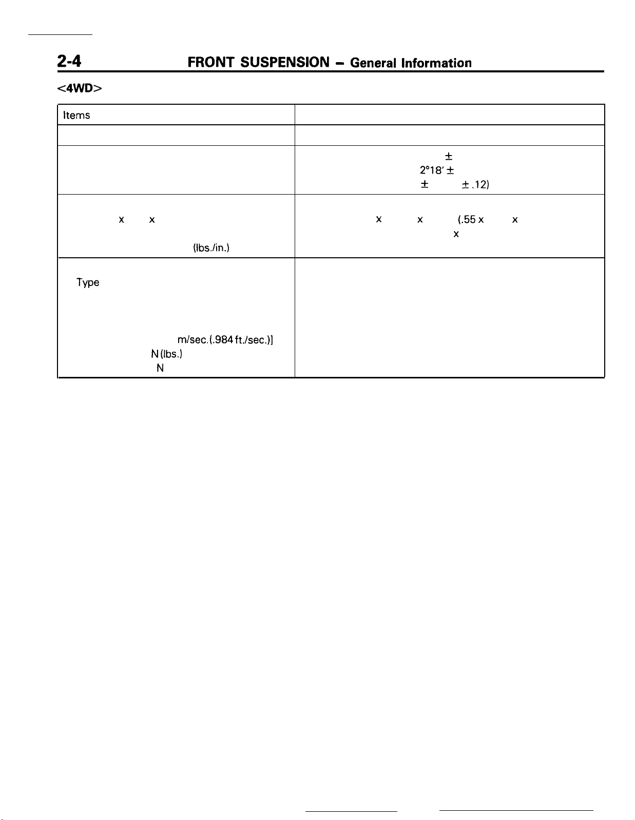
c4WD>
FRONT
SUSPENSION -
General Information
Items
Suspension system
Camber
Caster
Toe-in mm (in.)
Coil spring
Wire dia. x O.D. x free length
Coil spring identification color
Spring constant
Shock absorber
Type
Max. length
Min. length
Stroke
Damping force [at 0.3
Expansion N
Contraction
mm (in.)
N/mm
mm (in.)
mm (in.)
(Ibs.)
N
(Ibs.)
mm (in.)
(Ibs./in.)
m/set. (.984 ft./set.)]
Specifications
McPherson strut with coil spring and compression rod type
10’ +- 30’
2”18’ +
0 zk 3 (0 f
14.0 x 174.0 x 326.5
Hydraulic, cylindrical double-acting type
489 (19.25)
340 (13.39)
30’
(.55 x
Pink x 1
26 (146)
149 (5.87)
1,000 (220)
300 (66)
.l2)
6.85 x 12.9)
Page 23
FRONT
SUSPENSION
-
Anti-dive Geometry / Negative-offset Geometry
2-5
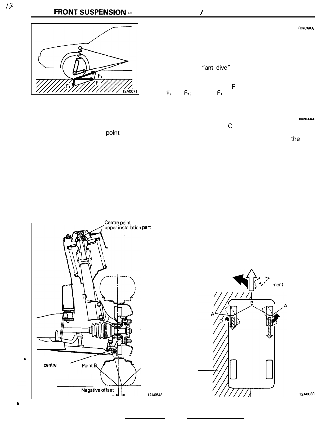
ANTI-DIVE GEOMETRY
Ordinarily, when the brakes are applied, the load is moved
toward the front of the vehicle as the result of inertial force, and
this causes the phenomenon known as “nose dive”, in which
the front of the vehicle is caused to tilt forward and downward.
For this front suspension, however, the suspension link design
-which has a high
arm is tilted forward in order to counteract the “nose dive”
phenomenon.
In other words, braking force F is divided into force components F, and
the front spring, with an effect that reduces the “nose dive”
phenomenon.
NEGATIVE-OFFSET GEOMETRY
For negative-offset geometry. the king pin offset
angle is outside the center point of tire-to-ground
contact. Thus, for example, if a tire on the right side
is punctured during driving, or if the brakes are
applied while the left tires are on a slippery surface
(ice, etc.), the vehicle would be inclined to swerve to
the side (in this case the right side) of greater road
surface resistance to the tires, but, because of the
negative-offset geometry construction, a certain
force would be generated to cause rotation in
direction C, employing point A as the fulcrum point.
At the same time, there would be generated at the
tires on the opposite side a corresponding force to
cause rotation in direction D, also employing point A
as the fulcrum point, but, because that force is
Centre ooint
of
strut
Pati
RO2cAAA
“anti-dive”
F2;
of these, F1 acts in the direction that expands
effect- is such that the lower
AOZDAAA
greater in direction C (where road surface resistance
is greater), the tires themselves will tend to turn in
the left direction. As a result,. because
t.he
tires
automatically countersteer in the left direction, even
though the force applied to the vehicle by the road
surface resistance is to the right, the system thus
functions to maintain the vehicle on a relatively
straight-ahead course.
NOTE
The king pin offset is the distance from the center
point of tire-to-ground contact when a line (extended to the road surface) is drawn to connect the
ball joint center point and the center point of the
strut upper installation part.
Ball joint
centre
point
<B<\r
L
t
Point A
12AO548
Direction
of
tire
movement tendency
Icy surface
Direction
of
travel
Direction
--
>
;’*Jvehicle move-
f
4
,
:’
ment
”
of
tendency
12AOO30
Page 24
----
2-6
FRONT
SUSPENSION
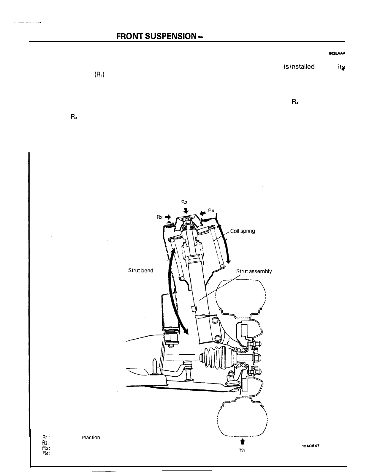
OFFSET SPRING
Because struts are installed at an angle, the road
surface reaction force
to act vertically upon the tyre centre, and that force
tries to bend the strut toward the inside of the
vehicle. When this happens, the force trying to bend
the strut toward the inside of the vetiicle acts upon
the strut bearing component as bending moment
reaction force FL (because the upper part of the strut
is fixed in place), thus increasing the friction of the
bearing, and, as a result of the bending of the strut,
amplifying the moving resistance of the shock
absorber.
(RI)
applied to the tyres tends
-
Offset Spring
Ro2EMA
Then, because the coil spring is installed so that
its
centre is greatly offset (toward the outside of the
vehicle) from the centre of the strut, the counteractive force for the spring tends to become great
toward the outside of the vehicle, thus resulting in
the generation of bending force FL opposite to the
bending of the strut, and thereby decreasing the
friction applied to the strut bearing. As a result, the
shock absorber’s internal movement friction is
reduced, thereby improving riding comfort as well
as the durability of components.
Spring counteractive
force
RI :
Road surface
R2:
Strut axial-reaction force
R3: Strut bend direction reaction force
R4: Strut bending force (by spring offset)
reaction
force
Page 25
FRONT
SUSPENSION
-
Lower
Arm / Stabilizer
2-7
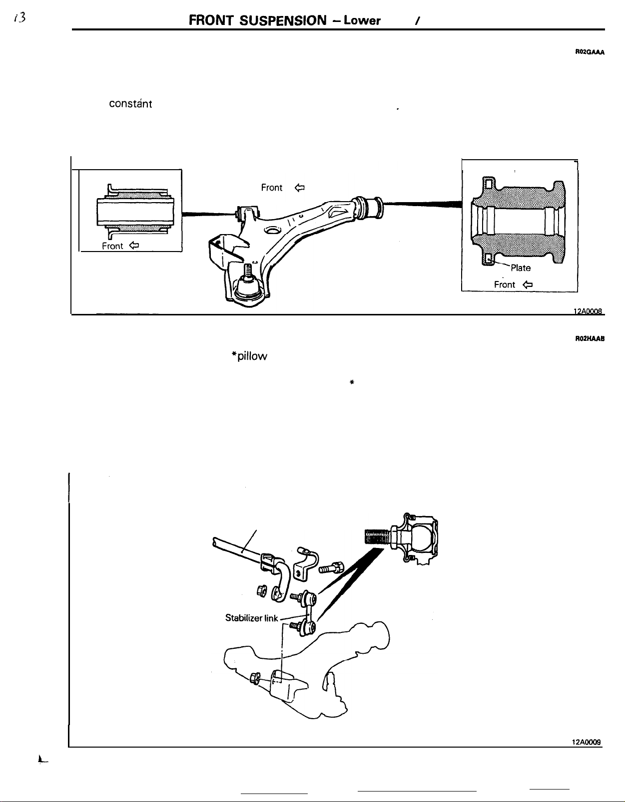
LOWER ARM
The lower arm is an A-type arm, and is connected,
via a rubber bushing, to the crossmember.
The rod bushing is optimum tuned, including the
spring constant of the arm bushing, to provide
“soft” characteristics relative to the front and rear
Arm bushing
,m
STABILIZER
ROZGAAA
and “hard” characteristics relative to the left and
right, so that road surface impacts during travel are
alleviated, and also so that changes of alignment
caused by lateral forces are reduced, thus assuring
excellent I driving stability.
Rod bushing
ROZHAAB
The stabilizer mounting uses
adoption of a stabilizer link with a pillow ball on each
end increases the link stiffness and ensures the
effective operation of the stabilizer bar even when a
*pillow
Stabilizer bar
balls. The
small rolling motion occurs,
NOTE
* Pillow ball: Ball joint not preloaded.
Pillow ball
4--
12AOOOS
Page 26
2-8
FRONT
SUSPENSION
-
Front Axle
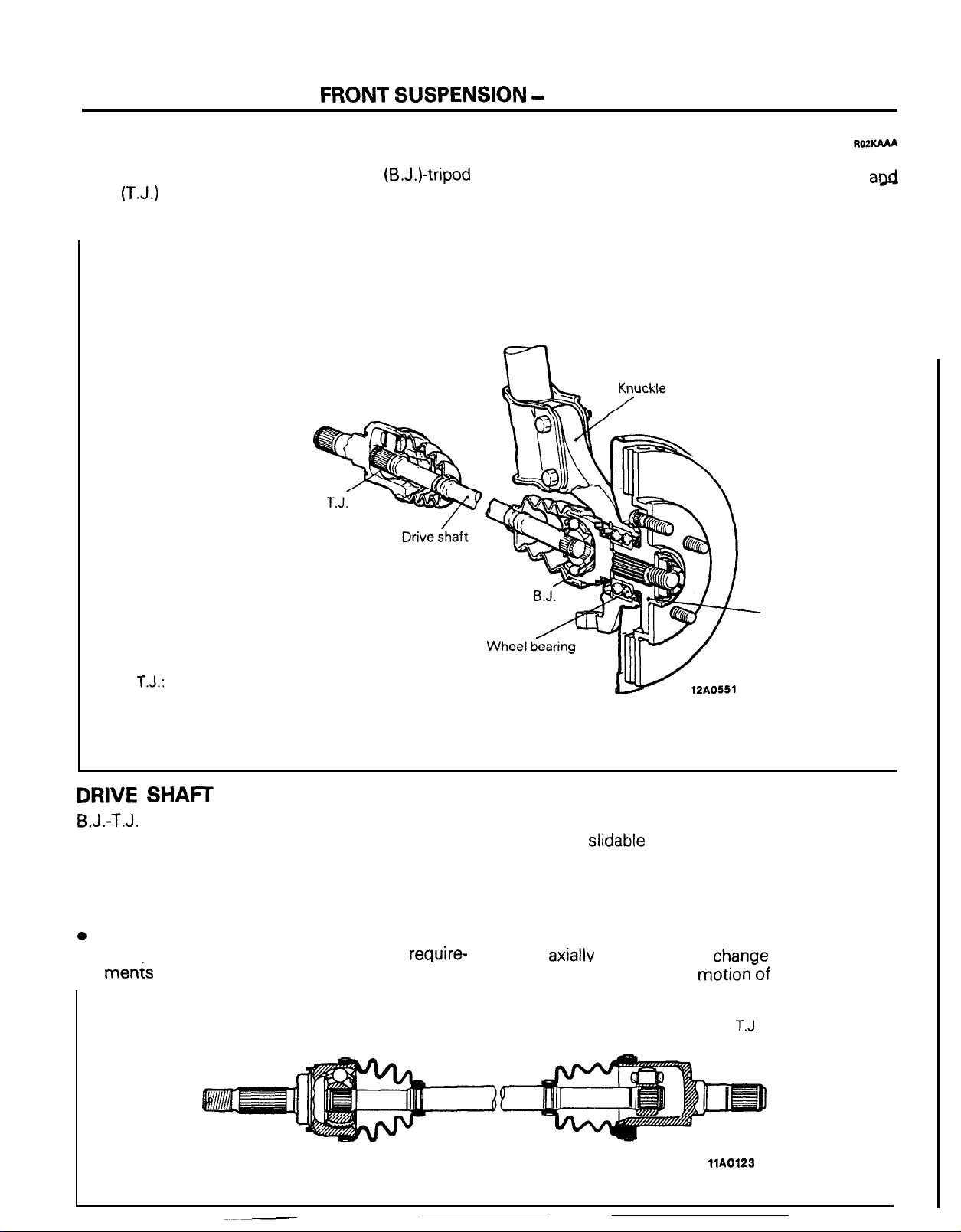
FRONT AXLE
The drive shaft is of the Bit-field joint
joint
(T.J.)
type. This type features high power
transmission efficiency and low vibration and noise.
(B.J.)-tripod
ROPKAAA
The knuckle has the wheel bearing assembled
a@
the hub press-fitted. The drive shaft and hub are
spline-coupled.
T.J.:
Tripod Joint
B.J.: Birfield Joint
DRIVE
B.J.-T.J.
SHAFT
constant velocity joint combination maintains speed completely even when flexed, can
withstand heavy loads and shock and offer high
power transmission efficiency. Their special fea-
tures are outlined below.
B.J.
0
Large operating angle
l Compact size and decreased space
require-
me&
B.J.
Hub
T.J.
l Axially
l Smaller sliding resistance
slidable
Taking these characteristics into account, B.J. is
adopted on the wheel side of the shaft, as it can
make large deflections when the tire is steered and
T.J. is adopted on the transmission side, as it can
slide
axiallv
to absorb the
between joints caused by
chanae
in the distance
motionWof
T.J.
the suspension.
llA0123
Page 27
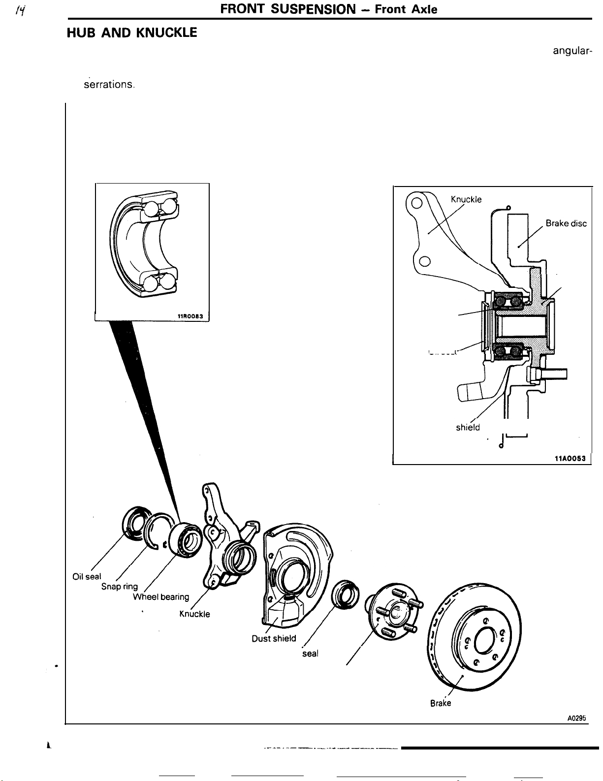
HUB
AND
FRONT
KNUCKLE
SUSPENSION -
The construction of the hub and knuckle consists of
the wheel bearing assembled to the knuckle and the
hub pressed in; the drive shaft and hub are coupled
by
&rations.
Front Axle
The wheel bearing is the double-row,
2-9
angular-
contact ball bearing type to withstand the lateral
(thrust) load. The installation of the brake disc and
hub are the outer disc configuration, thus improving
serviceability and also reducing rotation unbalance.
Hub
Wheel bearing
Oil seal
I
Dust shi&d
II I
llA0053
Oil
seal
..~ -- . ..- - . .._ ~._ __.- ----_ .__
/
Hub
Braie
disc
11 A0295
Page 28

3-1
REAR
AXLE SHAFT
DIFFERENTIAL
DIFFERENTIAL SUPPORT MEMBER
DRIVE SHAFT
........................................................
....................................................
........................................................
................
AXLE
CONTENTS
4
GENERAL INFORMATION
5
9
4
Construction Diagram
Specifications
VISCOUS COUPLING TYPE LIMITED
SLIP
Construction
Functions and features
Operation
....................................................
I
DIFFERENTIAL
....................................................
............................................................
RoJA-
................................
........................................
............................................
....................................
.
_
.L..
,,....
Page 29

.v:
3-2
-.-...-
.
REAR
AXLE
-
General Information
T
GENERAL INFORMATION
The differential carrier and axle housing have been
separated from each other, and D.O.J. and B.J.
drive shafts arranged in between, They are driven by
the axle shaft.
The axle shaft is supported by ball bearings (inner
CONSTRUCTION DIAGRAM
RO3BAAA
and outer) in the axle housing and are coupled with
the drive shaft with the companion flange in*
between.
The front of the rear suspension, and the rear
the differential carrier is mounted via the differential
support member to the body.
A
Crossmember
Differential
support
member
side
of
Differential carrier
12AO616
llA0339
Page 30
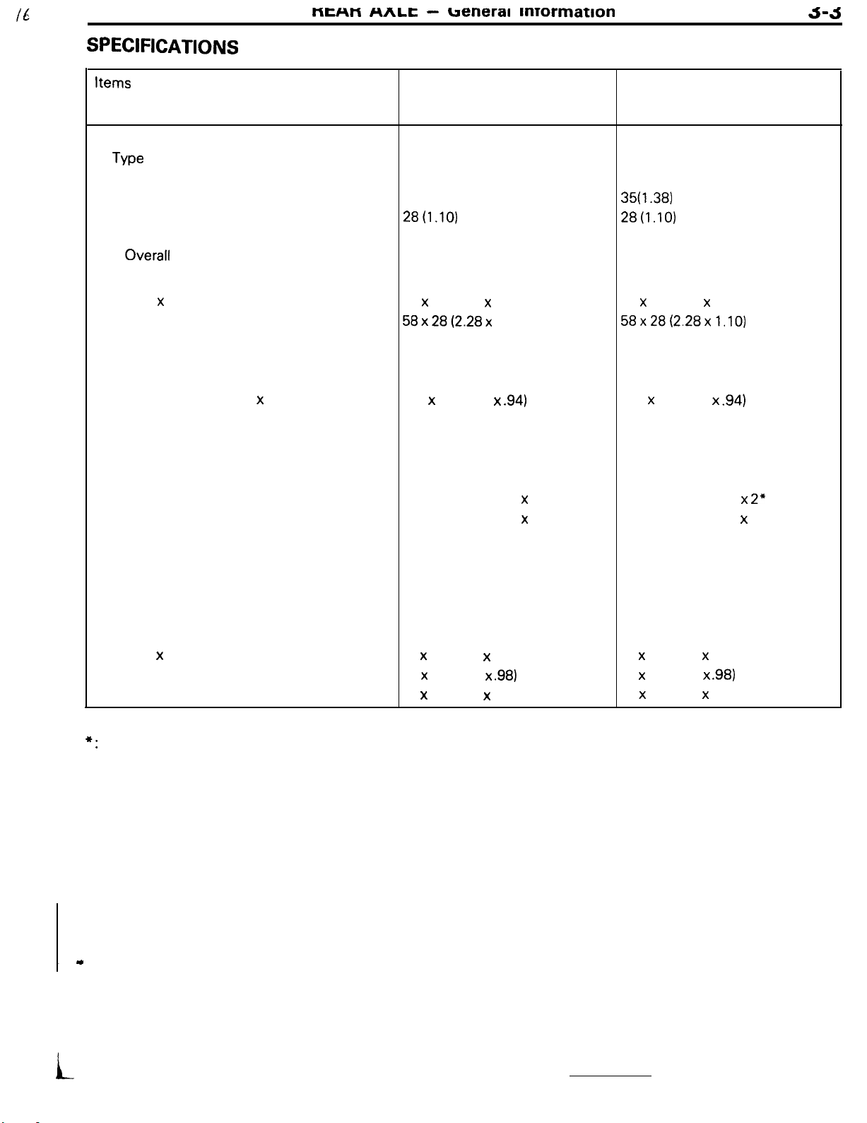
SPECIFICATIONS
MEHM
nnlL -
ueneral
mrormation
J-J
Items Conventional
Axle shaft
Type
Shaft dimensions
Outer bearing portion dia.
Inner bearing portion dia. mm (in.)
Center portion dia.
Overall
Bearing
O.D. x I.D.
Drive shaft
Joint type
Length (joint to joint) x diameter
Differential
Reduction gear type
Reduction ratio
Differential gear type and configuration
Side gear
Pinion gear
Number of teeth
Drive gear
Drive pinion
Side gear
Pinion gear
Bearing
O.D. x I.D.
length
mm (in.)
mm (in.)
Outer
Inner mm (in.)
Outer
Inner
Side mm (in.)
Front mm (in.)
Rear
mm (in.) 35 (1.38)
mm (in.)
mm (in.) 397 x 24 (15.6 x
mm (in.)
differential
Semi-floating type
28t1.10)
34.5 (1.36)
214.9 (8.46)
72 x 35 (2.83 x 1.38)
58x28(2.28x
D.O.J.
B.J.
Hypoid gear
3.545
Straight bevel gear x 2
Straight bevel gear x 2
39
11
14
10
72 x 35 (2.83 x 1.38)
62 x 25 (2.44 x
72 x 35 (2.83 x 1.38)
1.10)
.94)
.98)
Viscous coupling type
limited slip defferential
(option)
Semi-floating type
35f1.38)
28t1.10)
34.5 (1.36)
214.9 (8.46)
72 x 35 (2.83 x 1.38)
58x28(2.28x1.10)
D.O.J.
B.J.
397 x 24 (15.6 x
Hypoid gear
3.545
Straight bevel gear x
Straight bevel gear x 4
39
11
16
10
72 x 35 (2.83 x 1.38)
62 x 25 (2.44 x
72 x 35 (2.83 x 1.38)
.94)
.98)
2”
Note
*:
Denotes the gear (L.H.) which. is in a single body with the viscous coupling.
i
Page 31

3-4
REAR
AXLE
-
Axle Shaft / Drive Shaft
AXLE SHAFT
The axle shaft is a semi-floating type supported by
ball bearings (outer and inner) in the housing.
Companion
D.O.J.
Trailing arm
I
DRIVE SHAFT
R03cAAA
To prevent mud that may be deposited around the
bearing (outer), a dust cover has been provided.
I
flange
G
?
ust cover
llA0013
RO3OAAA
Birfield type constant velocity ball joints have been
provided for the drive shaft.
On the axle shaft side, the D.O.J. type has been
adopted to absorb the change in distance between
the joints that may be caused by the movement of
the suspension.
On the differential carrier side, the B.J. type has
been adopted which allows considerable flection in
keeping with the movement of the suspension.
Drive shaft and B.J.
On the axle shaft side, they are coupled with the
axle shaft with the companion flange in between.
On the differential side, they are spline coupled with
the side gears.
On vehicles with a viscous coupling type limited slip
differential, the right and left drive shafts are
different in length. In addition, the B.J. side of the
drive shaft (R.H.) is two-stage serration coupled.
D.O.J. Boot
_
D&e
shaft
(R.H.)
two-sta e serration
(ECLIPS!: Viscous coupling type
limited slip differential equipped
vehicles)
D.O.J. Inner
D.O.J. Outer race
I
llA0338
Page 32

REAR AXLE
-
Viscous Coupling Type Limited Slip Differential
3-a
DIFFERENTIAL
The differential uses lower torque bearings and
lower torque oil seals to improve power perform-
ante
and fuel consumption.
For faster differential cooling and higher reliability
during high speed operation, a differential carrier
with cooling fins has been adopted.
Side bearing space
Side gear
. /
ROlEAM
For better serviceability, spacers for adjustment of
final drive gear backlash have been inserted
tween the side bearing outer race and gear carrier.
A speed difference responsive type viscous
pling
type limited slip differential which provides
outstanding
Pinion gear
performance during operation
Differential cover
\
Q
be-
cou-
on a
ifferential case
VISCOUS COUPLING TYPE LIMITED SLIP DIFFERENTIAL
While the conventional mechanical type limited slip
differential uses a cam (differential pinion shaft) and
disc equipment
and spring seat in limiting the differential, the
compo.sed
of a friction plate, disc
Front wheel
Center differential
’
(viscous coupling)
Front
differential
T
viscous coupling type limited slip differential limits
the differential by use of a viscous coupling equip-
ment consisting of outer and inner plates and
silicone oil.
Rear wheel
Limited slip differential
assembly
, I
Differential
Differential limiting section
(viscous coupling)
RWEBAA
11KmI66
L.-
Page 33

3-6
I
REAR AXLE
- Viscous Coupling Type Limited Slip Differential
s
Differential case
,
Drive pinion
front bearing
‘Gear
B
cagier
Pir
Thrust
Side gear
washer
U3.H.)
Side gear
Pinion shaft
Side gear
(R.H.)
Viscous cokpling
(L.H.)
1
,
,,
Differential case
B
3r
Differential cover
I
Cokpanion
flange
I
Normal operating range
Difference in rotating speed between
right and left wheels
Remarks
l
A hump occurs when there is a large difference
in
rotatin
wheels.
violent shearing of the silicone oil in the
viscous
ture rises (the SI
torque abruptly rises. If the hump occurs, the
inner
and outer plates enter a directly coupled
(differential locked) state.
(rpm)
speed between the right and left
.!
lnce
the large difference causes
couplin
by the plates, the oil tempera-
7.
Icone 011
expands), and the
Bearing cap
Hump region
llAOO5r
Driv&
pinion
rear bearing
FUNCTIONS
(1) The viscous coupling type limited-slip differential
is functionally the same as
mechanical type which reduces slipping of the
rear wheels for better performance when travel-
ing on a rough road or when getting out of a
snowy or muddy surface.
(2) The viscous coupling type limited slip differential
responds to a difference in rotating speed and
has outstanding characteristics for use in an
on-road
characteristics in the normal operating range
between when power is ON and when it is OFF,
and provides better straight ahead stability and
running performance.
(3) When a single wheel is slipping, a hump could
Drive gear
AND
4WD
vehicle, as it has no difference in
FEATURES
the
conventional
cause the differential to approach a locked state.
Provision is therefore made to provide a better
ability to get out even in cases of one in a million
such as a stuck state.
llAo337
Page 34
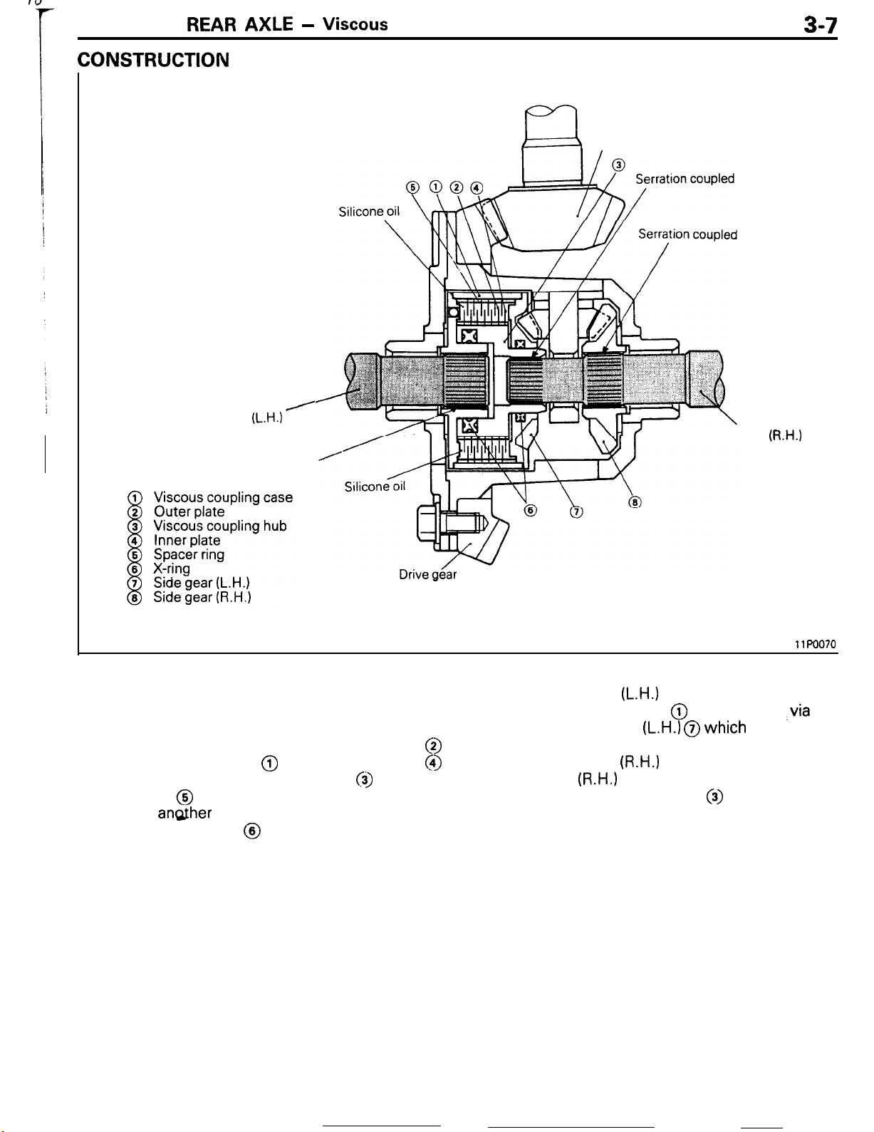
REAR AXLE -
CONSTRUCTION
Viscous
Coupling Type Limited Slip Differential
3-7
Rear drive
shaft
Serration coupled
/
(L.H.)
El
Drive pinion
Rear drive
shaft
(R.H.1
The viscous coupling type limited differential is a
“shaft-shaft” type consisting of the right and left
rear drive shafts and viscous coupling directly
coupled. The viscous coupling is a unit filled with
silicone oil and consists of the outer plates @
coupled with the case @ , the inner plates @
coupled with the viscous coupling hub
spacer rings @ arranged alternately to hold one
plate and angther with only a small spacing in
between. The X-rings @ are provided to prevent
(j)
, and the
11Po070
entry of the differential oil into the viscous coupling.
The rear drive shaft
the viscous coupling case @ and coupled
case with the side gear
body with the-viscous coupling case.
The rear drive shaft
the side gear
with the viscous coupling hub 0) .
The viscous coupling must not be disassembled.
(R.H.)
(L.H.)
is serration coupled with
,via
the
(L.H.) @which
(R.H.)
is serration coupled with
and its end serration coupled
is in a single
Page 35

w
3-8
REAR AXLE - Viscous
Coupling Type Limited Slip
Differential
OPERATION
Drive force smaller
(Slipping side)
Rear drive shaft
(L.H.1
(Left wheel)
resistance smaller)
I
If a difference in rotating speed occurs between the
right and left wheels, the viscous coupling case @
and viscous coupling hub @ relatively rotate with
the same difference in rotating speed as the rear
drive shafts. As a result a differential limiting torque
is generated by the shear resistance of silicone oil
and helps suppress the differential (slipping).
Drive force
(Grippina
larger
side)
Rear drive shaft
(R.H.1 (Right
wheel)
11
PO071
For example, assume that the right wheel rotates at
20 rpm due to the road surface resistance, whereas
the left wheel rotates at 30 rpm. The difference in
rotating speed between the right and left wheels is
10
rpm. Since the viscous coupling is provided
between the right and left wheels, a differential
limiting torque compensating for the difference of
10 rpm in rotating speed is transmitted from the left
wheel to the right one.
Therefore, a larger drive force is transmitted to the
right wheel rotating at the lower speed.
Page 36

REAR
AXLE
-
Differential Support Member
3-9
DIFFERENTIAL SUPPORT MEMBER
The differential support member supports the rear
side of the differential carrier. That end of the
member which is mounted to the body is elastically
supported by use of rubber bushings.
Section A-A
Differential support
member
llA0297
ROJFAAA
c
Differential
support member
\
Differential carrier
Page 37

BRAKES
SERVICE
GENERAL INFORMATION
Construction
Features
Specifications
PARKING BRAKE
Construction Diagram
Diagram
............................................................
....................................................
................................................
................................
........................................
........................................
AND
CONTENTS
2
2
2
2
7
7
PARKING
SERVICE BRAKES
Front Disc Brake
Rear Disc Brake
Specifications
Arrangement of Brake Lines
X
................................................
................................................
................................................
....................................................
........................
Page 38

5-2
BRAKES
GENERAL INFORMATION
-
General Information
The service brakes are a brake system featuring
excellent braking force and a high level of reliability
and durability.
All models are equipped with four-wheel disc brake
SPECIFICATIONS
Items
Service brake
Parking brake
Front
Rear
Specifications
Ventilated disc
Solid disc
Mechanical rear wheel braking type
FEATURES
Improved braking performance
1. Adoption of
4-wheel
disc brake on all models.
system as a brake system matching the
superb driving performance. Models with turbocharger are equipped with a 7
booster for lower brake pedal depression efforts.
Improved serviceability
1. Adoption of an outer disc system on the rear
brake discs of all models.
2. Adoption of a white reserve tank cap for the
master cylinder.
+
8 inch tandem brake
vehicle
CONSTRUCTION DIAGRAM
Proportioning
valv
Front disc brake
Page 39
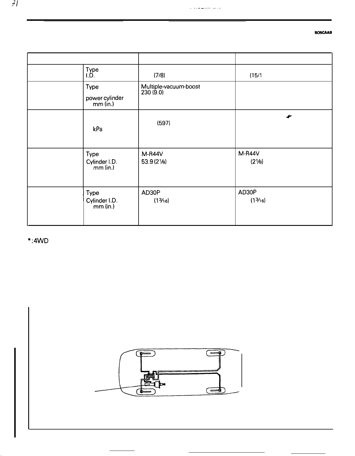
SERVICE BRAKES
SPECIFICATIONS
BRAKES
- Service Brakes
5-3
Items
Master cylinder
Brake booster
Proportioning valve Type
Front brakes
Rear disc brakes
$e
TYpe
powmermc&;der
I
mm (in.)
. .
Effective
Split point 4,200
Decompression 0.3
ratio
Type
cyhnxLy.
Clearance
adjustment
Type
Cyl~itl;.~.
Clearance
adjustment
kPa
(psi)
dia.
of
Non-Turbo
Tandem (with level sensor)
22.2
y3tt$;ivacuum-boost
Dual type
M-R44V
53.9
Automatic
AD30P
30.1
Automatic
Turbo
(718)
type
(597)
(2’/8)
(13/16)
Tandem (with level sensor)
23.8 (15/l 6)
Multiple-vacuum-boost type
Front side: 180 (7.0)
Rear side: 205 (8.0)
Dual type
4,200 (597)
0.3 or 0.4”
M-R44V
53.9
Automatic
AD30P
30.1
Automatic
c
(2%)
(13/16)
NOTE
*:4WD
X ARRANGEMENT OF
The X arrangement of brake lines is the
BRAKE LINES
arrange-
ment by which the right front and left rear and the
left front and right rear are connected, so that the
Master cylinder
braking force will be applied at the front’ and rear
wheels even in the unlikely event of a malfunction
of failure of one system.
14AO454
Page 40
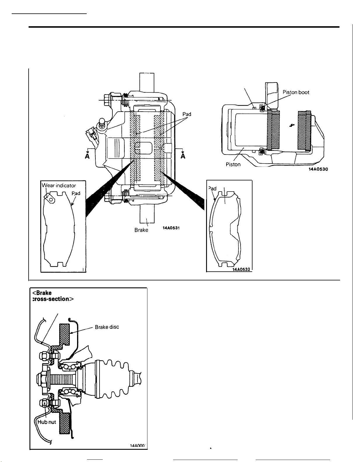
5-4
BRAKES
-
FRONT DISC BRAKE
The front brake is the
M-R44V
type featuring highly
efficient heat dissipation, quick recovery of braking
force when wet, and highly stabilized braking force.
Service Brakes
Section A-A
Piston seal
14AO530
,ad Shim
14AO533
<Brake
disc installation
xoss-section>
Disc wheel
Braki
disc
14A0531
0
14A0532
In addition, disc removal and installation is made easy by the
outer disc system, in which the brake disc is installed to the
disc wheel by the hub nuts.
.
Page 41
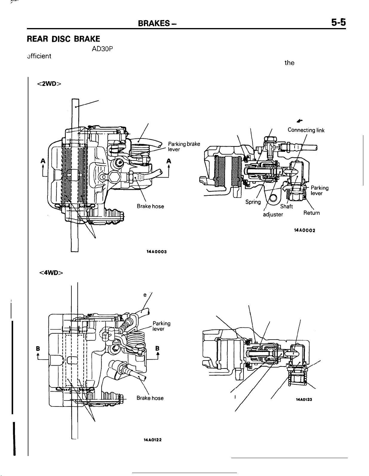
7-.
BRAKES
- Service Brakes
REAR DISC BRAKE
‘he rear brake is the
tifficient
heat dissipation, quick recovery of braking
force when wet, and highly stabilized braking force.
<2WD>
AD30P
Brake disc
type, featuring highly
5-5
The brake system incorporates an auto adjuster that
automatically adjusts the clearance between the
pad and brake disc when
depressed.
Section A-A
t.he
brake pedal is
<4WD>
u
I-
Pad
Brake disc
Parking brake cable
14A0003
Parking brake
cable
/
brake
brak
Piston boot
Piston boot
\
Piston seal Piston
\
Auto
spindle
Section B-B
Piston seal
\
Adjuster
Piston
&
Ret&n
14AOOO2
Connecting link
I
brake
spring
Parking
brake
/
lever
/
Spring
/
Auto adjuster spindle
Pad
14A0122
/
Shaft
Return spring
14A0123
Page 42
5-6
BRAKES
- Service Brakes
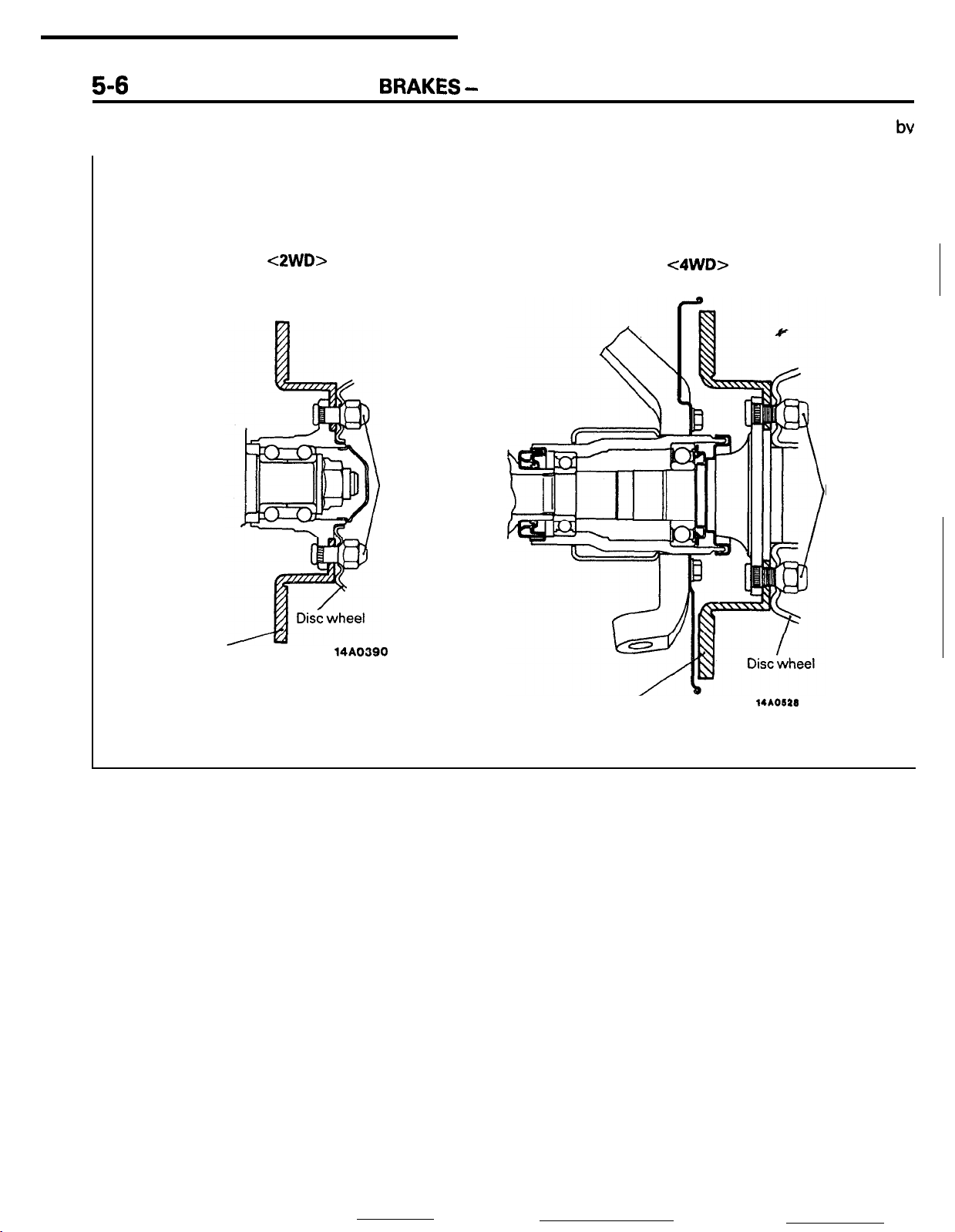
In addition, disc removal and installation is made
easy by the outer disc system, in which the brake
Brake disc installation cross-section
<2WD>
Hub nuts
disc and the disc wheel are installed to the hub
the hub nuts.
<4WD>
nuts
Hub
bv
Brake disc
14AO390
Brake&c
14AO622
Page 43

BRAKES
-
Parking Brake
5-7
PARKING BRAKE
The parking brake is of the mechanical rear wheel
braking type.
The parking brake is offset toward the driver’s seat
from the vehicle centerline for greater ease of
operation.
CONSTRUCTION DIAGRAM
ROSDMB
The parking brake
cable
is of the V-type and is
accessible for adjustment through the service hole
provided in the floor console.
Y
<4WD>
14AO391
14A0626
Page 44

til
i
r--
_..
CLUTCH
CONTENTS
_ _ -
b
6-1
-.-.
CLUTCH CONTROL
Inter-lock Switch
r-
. . . . . . . . . . . ..*..............................
. . . . . . . . . . . . . . . . . . . . . . . . . . . . . . . . . . . . . . . . . . . . . . . .
2
3
GENERAL INFORMATION
Specifications
. . . . . . . . . . . . . . . . . . . . . . . . . . . . . . . . . . . . . . . . . . . . . . . . . . . .
. . . . . . . . . . . . . . . . . . . . . . . . . . . . . . . .
2
Page 45
.__...e-
6-2
CLUTCH
-
General Information / Clutch Control
GENERAL INFORMATION
The clutch is the dry single-plate diaphragm type:
hydraulic pressure is used for the clutch control.
SPECIFICATIONS
Items
Clutch operating method
Clutch disc
Type
Facing diameter
O.D. x I.D.
Clutch cover assembly
Type .
Clutch release cylinder
I.D. mm (in.)
mm (in.)
Non-turbo
Hydraulic type
Single dry disc type
215 x 140 (8.5 x 5.5)
Diaphragm spring
strap
drove
type
20.64
(13/l
6) 19.05
Turbo
Hydraulic type
Single dry disc type
x
150 (8.9
225
Diaphragm spring
strap drive type
(314)
x5.9)
ROBBMA
Clutch master cylinder
I.D.
mm (in.)
15.87 (10/l 6)
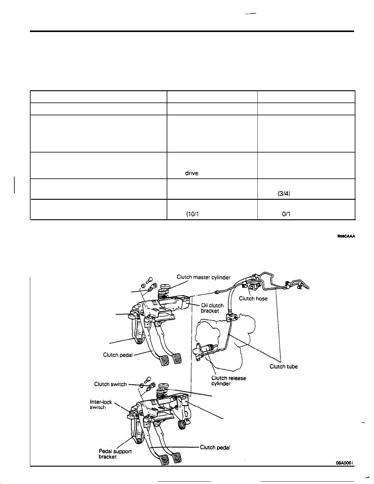
CLUTCH CONTROL
In order to prevent sudden movement of the vehicle
when the engine is started, an inter-lock switch has
been equipped (within the pedal support bracket),
<Non-turbo>
Clutch switch
Inter-lock
switch’
Pedal support bracket
<Turbo>
15.87
(1
O/l
6)
The clutch switch for the auto-cruise control system
has been equipped at the pedal support bracket.
Clutch master
Oil
clutch bracket
cylinder
Page 46
-.
.
.- ,..__ _. I-.,
. . . . -. .
“-Ix.. ...~‘,.;;&;,-*~;
Inter-lock switch
CLUTCH
INTER-LOCK
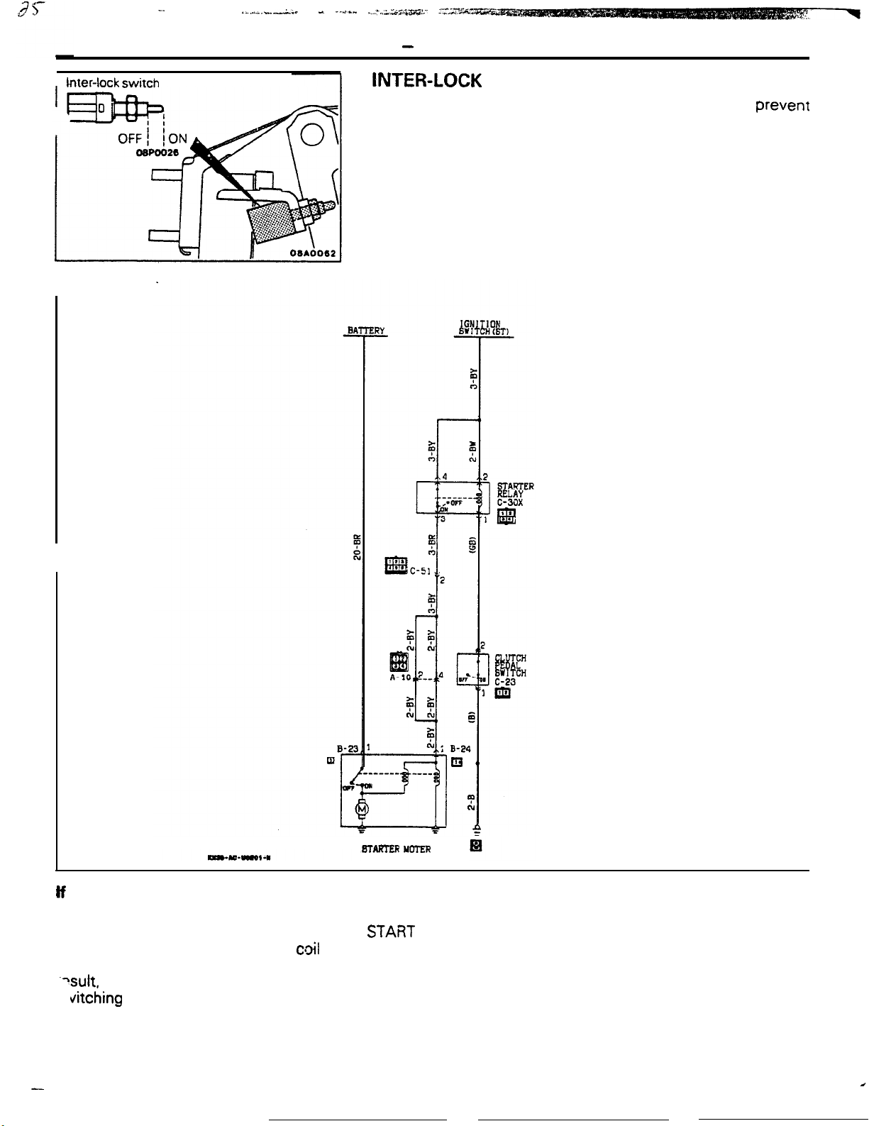
The inter-lock switch is a switch provided in order to prevent
sudden movement of the vehicle when the engine is star-ted.
Thus, the starter motor will not be switched ON unless the
clutch pedal is depressed, thereby switching OFF the inter-lock
switch.
NOTE
The inter-lock switch is normally ON; it is switched OFF when
the clutch pedal is depressed.
-
Clutch Control
SWITCH
6-3
If the Clutch Pedal is Not Depressed:
Because the inter-lock switch is switched ON when
the ignition switch is switched to the
position, electricity flows from the
cloil
of the starter
relay, through the inter-lock switch, to ground. As a
?sult, the contacts of the starter relay separate,
vitching
it OFF, and the starter motor is therefore
not activated.
-
BTAFTER YCTER
STABT
When the Clutch Pedal is Depressed:
The inter-lock switch is switched OFF when the
clutch pedal is depressed. If the ignition switch is
then switched to the START position at this time,
the flow of electricity to the coil of the starter relay
will be interrupted. the contacts of the starter relay
will close, switching it ON, and the starter motor will
be activated.
Page 47

COOLING
CONTENTS
R07A-.
_
GENERAL INFORMATION
Coolant
Specifications
RADIATOR AND COOLING FAN
Flow
....................................................
....................................................
. . . . . . . . . . . . . . . . . . . . . . . . . . . . . . . .
.._.................
2
TRANSAXLE FLUID
2
TWO-SPEED FAN CONTROL SYSTEM
4
4
Control System Circuitry Diagram
COOLER .
.._........._.._...._......._..
................
................
5
6
6
I
I
Page 48
7-2
COOLING
-
General Information
GENERAL INFORMATION
/
Radiator hose.
Radi
The cooling system is the liquid-cooled,
upper
Radiator hose
lower
Heater hoses
forcedcirculation type of system. The cooling (radiator) fan
is the electric motordriven type; the fan is driven by
Watei
Heater
pump
the motor only when necessary, and it functions to
efficiently regulate the temperature of the engine
coolant, thereby reducing losses of engine output
power.
Ro7BAAA
MAO1 03
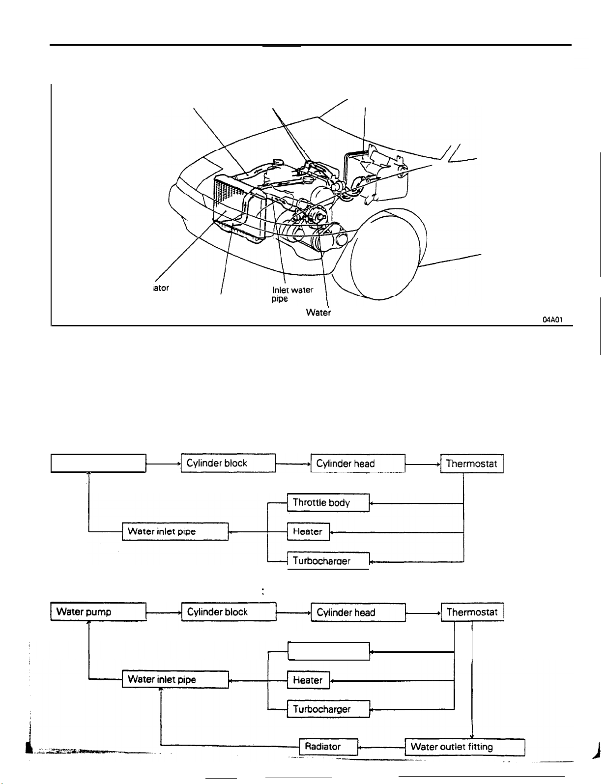
COOLANT
FLOW
The cooling system is liquid cooled, forced circula-
tion type. The engine coolant circulates as follows.
When engine is cold (Thermostat closed):
Water pump
T
When engine is warm (Thermostat open)
1
:
Throttle body
+m
I
t
Page 49

7’
IF---
CLUTCH
-
General Information
,,,.1:.;: ~&~~Lx.*.*. .Ihcin.*L-..r-‘- --a’ -.-
I ’
7-3
<Non-turbo>
Throttle body
<Turbo>
tedperat&
Water
gauge unit
I
From raclw
Water inlet
6cOO0,8
Water
.
pump
pipe
Page 50

----------------l-~)..
7-4
CLUTCH
General Information / Radiator and Cooling Fan
-
SPECIFICATIONS
Items
Water pump
Type
Delivery rate
Thermostat
We
Valve opening temperature
Drive belt
lit.
(qt.I/min.
“C (“F)
RADIATOR AND COOLING FAN
The radiator is of the corrugated-fin type.
The full-shroud type cooling (radiator) fan is em-
ployed in order to improve the cooling performance.
Specifications
Centrifugal impeller type
Max. 140
Wax type with jiggle valve
88
V-ribbed type
(190)
(148)
at 6,000
rpm
RO’ICMA
Radiato
Lower insulator
Uooer
insulator
Condenser
Therm0
switch
tank
--fyi$f&
Transaxle fluid cooler hose
<An>
Condenser
/
fan for
air conditioner
Page 51

COOLING
- Radiator and
Cooling
Fan
/
Transaxle
Fluid Cooler
7-5
Cross-section
Radiator
installatio
Lower insulator
TRANSAXLE
FLUtD
A flexible support system is used at the installation points of
the radiator in order to reduce the transmission of vibration and
noise to the body.
04*0101
COOLER
On vehicles provided with automatic transaxle, the
radiator has a transaxle fluid cooler that improves
soling efficiency of the transaxle fluid.
Transaxle
Radiator
Transaxle
fluid cooler
The transaxle fluid cooling path is as described
the figure below.
Transaxle fluid cooler
in
Page 52

_---.__ -
_.__-.
7-6
COOLING
-
Two-speed Fan
TWO-SPEED FAN CONTROL SYSTEM
CONTROL SYSTEM CIRCUITRY DIAGRAM
MA,N
FlJ6IBLE LINK@
I
!mpG2
6lm m16LE Llrn Q
-
.,D
,
Control
System
Y
Therm0
sensor operation modes
ON at
85°C (185°F)
or higher
This system functions to detect the operation mode
of the air conditioner, the coolant temperature, etc.,
by way of the air conditioner switch, the therm0
and to regulate the speed of the cooling (radiator)
fan and of the condenser fan to either the low speed
or the high speed.
sensor (for the radiator fan) and air therm0 sensor,
Switch/Sensor conditions
Therm0
Air conditioner switch
OFF
OFF
I
ON
ON
,
NOTE
The contact of the therm0 sensor is closed at the ON setting and open at the OFF setttng.
t
sensor
OFF
ON
-
OFF
ON
Air thetmo sensor
LOW
HIGH
LOW
HIGH
HIGH
LOW
I
HIGH
Cooling
I
OFF
ioN
LO
Fan rotating condition
(radiator)
OFF OFF
OFF
HIGH
HIGH OFF
LOW
HIGH
HIGH
HIGH
fan
HI
Condenser fan
OFF
OFF
LOW
HIGH
HIGH
HIGH
Page 53
ELECTRICAL
DIAGNOSIS SYSTEM - CHECK
CONNECTORS
ENGINE ELECTRICAL
Alternator
Ignition System
Ignition TimingControl
Starter Motor
SES
....................................................................
Dedicated Fuses
MainFusibleLinks
Multi-purpose Fuses
Sub-fusible Links
INSPECTlON TERMINAL
JUNCTION BLOCK
ConstructionofJunction
. . . . . . . . . . . . . . . . . . . . . . . . . . . . . . . . . . . . . . . . . . . . . . . . . . . .
........................................
............................................................
................................................
System
....................................................
................................................
............................................
........................................
................................................
. . . . . . . . . . . . . . . . . . . . . . . . . . . . . . . . . . . .
. . . . . . . . . . . . . . . . . . . . . . . . . . . . . . . . . . . . . . . . . . . .
Block
CONTENTS
LlGHTlNG
4
23
23
25
........................
. . . . . . . . . . . . . . . . . . . . . . . .
27
24
15
5
5
Delayed Switch-off Dome Light
Headlight
REUYS,
SENSORS
Auto-cruise Control System
Automatic
Automatic
Headlight (Pop-up System)
Heater and
Multi-point Fuel
Other
THEFT-ALARM
Operation
----
............................................................
....................
............................................................
CONTROL UNITS AND
. . . . . . . . . . . . . . . . . . . . . . . . . . . . . . . . . . . . . . . . . . . . . . . . . . . . . . . . . . . .
. . . . . . . . . . . . . . . . . . . . . . . . . . . .
Seat
Belt
Transaxle
Air Conditioner
Relays and
SYSTEM
............................................................
. . . . . . . . . . . . . . . . . . . . . . . . . . . . . . . . . . . . . . . .
. . . . . . . . . . . . . . . . . . . . . . . . . . . . . .
. . . . . . . . . . . . . . . . . . . . . . . . . . . .
. . . . . . . . . . . . . . . . . . . . . . . . . . . . . . . .
Injection
ControlUnits
System
....................................
. . . . . . . . . . . . . . . . . . . .
. . . . . . . . . . . . . . . . . . . . . . . .
.._.......
16
22
16
7
10
10
9
12
11
7
13
32
32
Page 54

8-2
ELECTRICAL - Fuses
FUSES
MAIN FUSIBLE LINKS (DIRECT TO
The main fusible links are the cartridge type and are directly
mounted to the
No.
I 1 I
L
SUB-FUSIBLE LINKS (IN RELAY BOX)
Subdivided into seven electrical circuits, the sub-fusible links
function to protect the circuits; the cartridge-type fusible links
are located in the relay box within the engine compartment.
I
MPI circuit
Radiator fan motor circuit
2
Ignition switch circuit
3
No.
I
Alternator circuit, sub fusible-
link
0, 0, @, 0,
Defogger circuit
(+)
terminal of the battery.
Circuit
I
Circuit
@
Housing
BATTERY)
Rated
colour capacity (A)
Blue
Pink 30
Pink 30
Hcyy
Black
Green
20
I
Rated
capacity
80
40
(A)
I
I
1
L
Automatic seatbelt circuit,
dedicated fuse @circuit
Pop-up circuit.
alternator circuit
5
Power window circuit
Multi-purpose fuse 0. @. 0.
6
ed%$?&e
!F
Headlight circuit.
7
dedicated fuse
@circuit
0. @I. @circuit
@.
Pink
Pink
Pink
Green
Green
30
30
30
1
40
40
I
b&i -e?z5mm..
-_
--
-.--- --.
.._
. .
__-___
-
----_
4
Page 55
r
Power supply circuit
I
Fuse No.
ELECTRICAL - Fuses
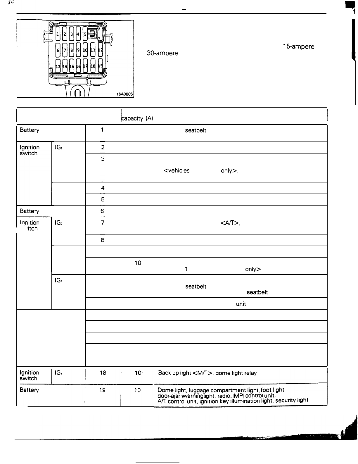
MULTI-PURPOSE FUSES
The multi-purpose fuses are located within the junction block at
the lower part of the instrument panel (at the driver’s seat side).
These fuses are all the blade type; 1 O-ampere,
Rated
apacity
30-ampere
(A)
fuses are used.
Load circuit
15-ampere
8-3
and
q
I
I
Battery
lonition
t-
,itch
IGz
ACC
IG,
ACC
IGI
9
10
11
10
10
10
15
15
10
15
10
10
Automatic seatbelt control unit, buzzer, passing control relay,
key reminder switch, theft-alarm starter relay
Air conditioner control unit, air conditioner switch, heater relay,
power window relay, defogger timer, daytime running light relay
2 <vehicles for Canada
Canada only?
Radio
Cigarette lighter, remote controlled mirror
Door lock relay, door lock control unit
Auto-cruise control unit
inhibitor switch, combination meter
Wiper motor, washer motor, intermittent wiper relay
Horn, headlight relay, theft-alarm control unit, daytime running
light relay 1 <vehicles for Canada
Auto-cruise control unit, auto-cruise control actuator,
automatic seatbelt control unit, theft-alarm control unit,
combination meter, warning light, seatbelt timer
only>,
<A/T>,
transistor relay <vehicles for
AA control unit,
only>
Battery
12
13
14
15
16
17
10
10
30
15
Turn-signal and hazard flasher
Theft-alarm horn relay
Blower motor
Stop light
Back up light
Dome light. luggage compartment
door-ajar
AK control unit, ignition key illumination light.
!
CM/T>,
warntng
dome light relay
light, radio, MPI control
u.nit
Irght, foot. Irght.
unrt.
security light
Page 56

_--
8-4
ELECTRICAL - Fuses / Diagnosis System
DEDICATED FUSES
For high-load circuits, fuses dedicated to each individual circuit
are used.
The dedicated fuses are provided in the relay box of the engine
compartment.
warning
Circuit
light circuit
No.
I
1 1 Tail light circuit
2
Fog light circuit
3,.
Hazard
4 ) Upper beam circuit
5’
Air conditioner magnet
clutch circuit
I
6’
Condenser fan motor
circuit
NOTE
l
:
Air conditioner equipped models.
H,“d;;-;
I
Red
I
Red 10
Red
Red
I
Red
I
Yellow
Rated
canacitv (A)
I
10
I
10
10
I
10
I
20
I
I
I
I
I
6
543
DIAGNOSIS SYSTEM - CHECK CONNECTORS
The connectors for diagnosis of the following systems are
provided beside the junction block.
1. Multi-point Fuel injection System
2. Automatic
3. Diagnosis control
z. grm.rlnaFd
6:
Auto-cruise control
1
2
16R133l
Transaxle
vehicle speed
.
nmcwaB
.--.-__
:.
-.
Page 57
3i
ELECTRICAL
-
Junction Block
8-5
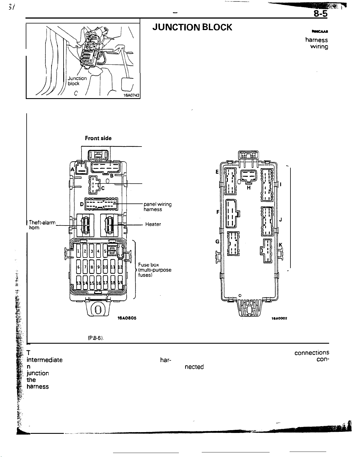
JUNCTION
The junction block is a feature in which wiring
connections are centralized for simpler and more reliable
harness connections.
The junction block is provided under the instrument
driver’s seat side.
CONSTRUCTION OF JUNCTION BLOCK
To engine
compartment
wiring harness
. No connection
BLOCK
_.
Rear side
hamess
panel
wiring
at the
To instrument
;;;+$ring
rheft-alarm
iom
relay
.’
./
%A0805
relay
NOTE
The alphabetical symbols on the connectors are associated with the
internal circuit diagrams
(PB-6).
he junction block is an integrated assembly of
ltermediate connection connectors of wiring
har-
ess, fuse box, and relay. On the front side of the
unction
le
block, the connectors for connections from
heater relay, fuse box, engine compartment
amess and instrument panel harness are provided.
To body
wiring harness
On the rear side, the connectors for connections
from the body harness are provided and are
netted
in the junction block as shown below.
con-
Page 58

__._._ -.. .-
8-6
INTERNAL CIRCUIT DIAGRAM
ELECTRICAL - Junction Block
I I
I I
rr,
Illll
Illll
III
III
-
-
-
I
I
-
r
”
L
NOTE
The alphabetical symbols on the connectors are associated with the
connector symbols
(P.8-5).
Page 59

ELECTRICAL
Relavs,
-
Control Units and Sensors
RELAYS, CONTROL UNITS AND SENSORS
The relays, control units and sensor for the various systems are located as described below.
ILTI-POINT
.
Air-flow sensor (incorporated within
barometric-pressure sensor and
intake air temperature sensor)
Crank angle sensor and top dead center sensor
Detonation sensor
EGR temperature sensor
<vehicles
Engine coolant temperature sensor
Idle switch
NOTE
The “Name” column is arranged in alphabetical order.
for California>
FUEL INJECTION SYSTEM
Name
<Turbo>
Symbol
A
C
F
E
B
D
Name
Magnet clutch relay
MPI control relay
MPI
control unit
Oxygen sensor
Throttle position sensor
Vehicle speed sensor (reed
switch)
ROBEAAC
Symbol
G
J
K
H
D
I
orated within barometric
re sensor and
Intake arr
7
(incorporated within
pressure sensor and intake
temperature
barometnc k
sensor)
arr
-4
L 1mo721
Page 60
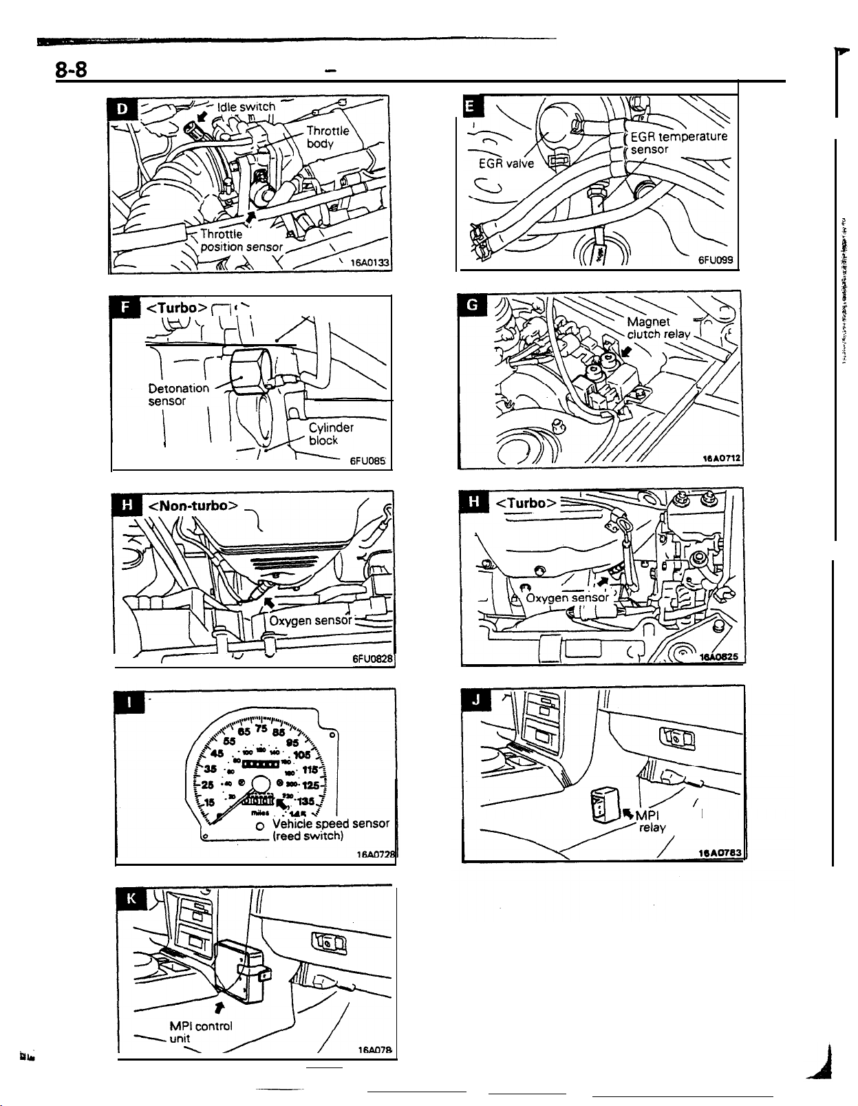
8-8
ELECTRICAL
Relays, Control Units and Sensors
-
<Turbo> (7 ! ’
1
/
7~
Intake manifold
,
lyJJr
I-
I . I
1J
-
6FlJO85Z
I
6FUO8281
b
MPI control
Page 61

33
ELECTRICAL
.- .1S~IUlj~%L...i-.
-
Relays, Control Units and Sensors
AUTOMATiC
:ontroi unit
Automatic transaxle fluid temperature
TRANSAXLE
Name
Symbol
D
B
sensor
MPI control unit
Pulse aenerator
A
D
B
NOTE
The “Name” column is arranged in alphabetical order.
Name
Pulse generator
B
Throttle position sensor
Vehicle speed sensor (reed switch)
Symbol
B
A
C
Automatic
transaxl
fluid temperature sen
13AO721
16440784
Page 62

-
I
I
1
__ .-
8-10
‘O-CRUISE CONTROL SYSTEM
I
AU
ELECTRICAL
Relays, Control Units and Sensors
-
_-
ps+%J
Vehicle speed sensor (reed switch)
AUTOMATIC SEAT BELT
Name
Automatic seat belt control unit
‘
Symbol
A Automatic seat belt motor relay
Name
Symbol
A0
Page 63

1
ELECTRICAL
-
Relays, Control Units and Sensors
HEATER AND AIR CONDITIONER
I
4ir
conditioner control unit
Air inlet sensor
Air therm0 sensor
Blower motor High relay
$x$enser
NOTE
The “Name” column is arranged in alphabetical order.
fan motor High-Low selecting
Name
Symbol
8-11
Name
D
F
F
E
C
Condenser fan motor relay
Engine coolant temperature switch
Heater relay
Magnet clutch relay
Radiator fan motor relay
Symbol
C
A
G
C
B
Page 64
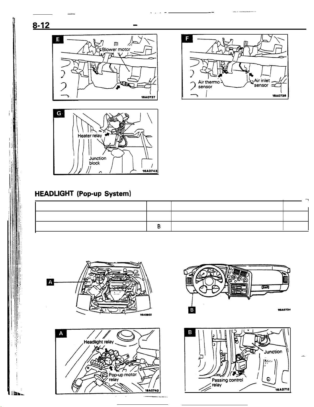
-
. . - --
--
__ .__-...
8-12
ELECTRICAL
Blower motor High relay
-
Relays, Control Units and Sensors
,,,A,
HEADLIGHT (Pop-up
Name
Headlight relay
Passing control relay
NOTE
The “Name” column is arranged in alphabetical order.
System)
Symbol
.A
-7
Name
Pop-up motor relay
B
Symt
A
+Junction
--
1
block
\
-
\
Page 65

ELECTRICAL
-
Relays, Control Units and Sensors
OTHER RELAYS AND CONTROL UNITS
8-13
Name Symbol
Alternator relay
Defogger relay
Defogger timer
Dome light relay
Door lock control unit
Door lock relay
Daytime running light relay
<vehicles
Fog light relay
Intermittent wiper relay (rear wiper)
Intermittent wiper relay (windshield wiper)
NOTE
The “Name” column is arranged in alphabetical order.
<Engine
for Canada only>
compartment and interior-front>
1,2
A
B
G
H
E
G
G
-
A
p
H
C
Name
Power window relay
Radiator fan motor relay
Seatbelt
Starter relay
Taillight relay
Theft-alarm control unit
Theft-alarm horn relay
Transistor relay <vehicles for Canada only>
Turn signal and hazard flasher unit
timer
<M/T>
Symbol
A
A
G
G
A
E
F
D
F
-
Y
Intermittent wiper relay
(built-in column switch)
z
I
Page 66
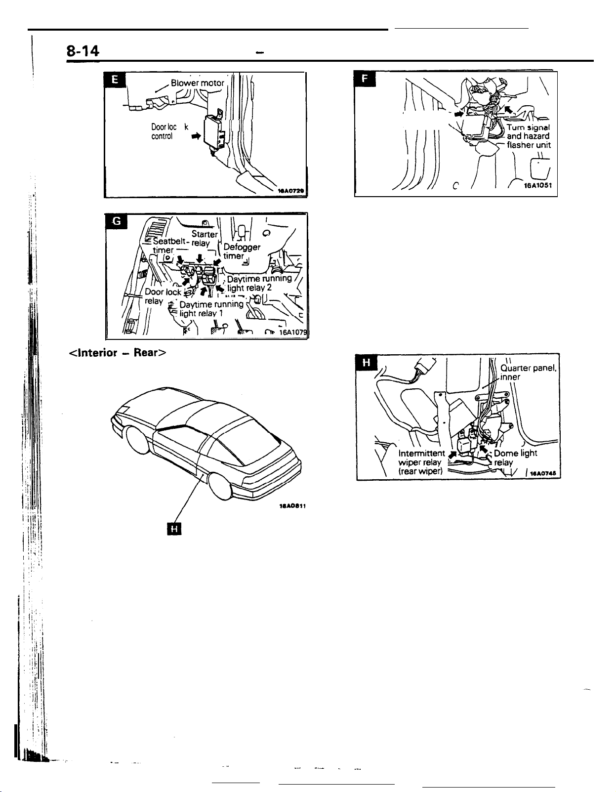
ELECTRICAL
k
~
u
b%YrF
unit or
Theft-alarm
control unit
-
Relays, Control Units and Sensors
7 II III
\I\\\
Theft-alarm
horn relay
<Interior -
Rear>
._
--. --- . ._.
Page 67

ELECTRICAL
INSPECTION TERMINAL
. .
.&L :
__,
-
Inspection Terminal
I
Name
Engine speed detecting terminal
Fuel pump check connector
Ignition timing adjustment connector
NOTE
The “Name” column is arranged in alphabetical order.
Symbol
C
A
B
Name
Oxygen sensor check connector
Self-diagnosis connector
-
Symbol
D
E
16Ao734
Page 68

8-16
ELECTRICAL - Lighting
LIGHTING
HEADLIGHT
The parallel-link pop-up headlights are employed
that move up or down vertically as they are turned
ON or OFF. They are aerodynamic to offer less
resistance to air when the vehicle is in forward
motion.
The headlights can be moved up and down with the
lighting switch or pop-up switch. An independent
headlight moving mechanism is provided for the
Ro3liAAA
right and left headlights: should one mechanism fail,
the other remains operative.
In addition, when the passing light is used, the
headlights are turned ON in the lowered position
without popping up.
There is also a manual knob installed that can be
used to move up and down the headlights manually
when maintenance is required.
Hinge
nual
knob
POD-UD
-r -r
motor
NOTE
See
P.8-12
for relays.
<DOWN position>
<UP Position>
Pop-up
motor
16AOWO
~
_
SpsernbI
y
Headlight
1RAoa50
CONSTRUCTION
’
Pop-up
The mechanism consists of the pop-up motor which moves the
headlights up and down. The hinge and link assembly connect
the pop-up motor to the headlight. When the pop-up switch or
lighting switch is turned ON, the pop-up motor is started
causing the link assembly to move the hinge, which results in
the headlight moving up. A parallel link system is employed for
the hinge, in which the hinge is moved about the two fixed
points as shown, which ensures that the headlights are moved
up and down vertically.
.
Page 69

ELECTRICAL - Lighting
8-17
Front turn
signal light
(Optical horn)
Pas+ing
The parallel-link pop-up headlight mean that the headlights are
facing forward even when they are in the lowered position.
When the passing light is used, therefore, the headlights are
turned ON and the light is radiated through the optical horn
rr,“;;
Manual Knob
The manual knob, located behind the pop-up motor, is used to
move up or down the headlights manually when maintenance
is required.
To operate the manual knob, remove the boot behind the
popup
disconnect the negative battery cable or remove fusible link
whenever the manual knob is to be operated.
Light
installed to allow the light through) of the side turn signal
motor and turn the knob clockwise. To ensure safety,
(4)
OPERATION
tieadlight
Switch position
f%+P
switch
NOTE
‘X”
indicates the resultant headlight operation or position. When the lighting switch
Operating Conditions
Lighting
switch
ON
Passing
switch
Lighting
switch
OFF
Passing
switch
UP
ON
OFF
ON
OFF
ON
OFF
ON
OFF X
X
X
X
X
X X
DOWN
is
Headlight
ON
X
X
X
X X
ON, it is in the “HEAD” position.
OFF
X
X
X
X
I
Page 70

8-18
HEADLIGHT RAISING OPERATION
1. Pop-up switch ON, lighting switch OFF
ELECTRICAL
-
Lighting
When the pop-up switch is turned ON, current from
fusible link @ flows through the up timer circuit of
the passing control relay, turning ON transistor Trl .
Current from Trl passes through the U contact of
the U/D (Up/Down) switch of the pop-up motor. This
means that current flows through the pop-up motor
relay, thus energizing the pop-up motor relay.
The energized pop-up
current from fusible link @flows through the pop-up
motor, which results in the headlights starting going
up. When the crank arm of the pop-up motor rotates
I
jj
bib,-.-.+. -- ----
--.__
*motor
relay means that
about 180” to the UP stop position, the contact of
the interlocking U/D switch changes from U to
which cuts off current to the pop-up motor relay. As
a result, the pop-up motor relay is de-energized and
no current flows from fusible link @ to the motor.
This results in the headlights staying in the fully-
raised position.
UP & DOWN TIMER CIRCUIT
Even if Up/Down operation of the pop-up headlight
becomes abnormal, the Up or Down timer (ON for
f
2 seconds) cuts the power supply to the
motor to protect the motor.
D,
POP-UP
5
Page 71

.
...>A . ..-rr7.e.~/._.
. .
. . .
,
ELECTRICAL -
2. Lighting switch ON, pop-up switch OFF
I
Ftmbk
mr 7
Fl
ie
IU
-
--
Lin
htina
Fusable
knk
.
8-19
When the lighting switch is turned ON (HEAD
position), current from fusible link @ flows through
the lighting switch, diode, and the up timer circuit of
the passing control relay. turning ON transistor Trl .
Then, as in 1, the pop-up motor relay is energized
causing the pop-up motor to start rotating, which in
turn results in the headlights being raised. Turning
ON (HEAD position) the lighting switch also ener-
gizes the headlight relay, causing the headlights to
be lit up.
Page 72

_
-. _
-.
__-
ELECTRICAL - Lighting
HEADLIGHT LOWERING OPERATION
1. Pop-up switch from ON to OFF, lighting switch OFF
r-
A
r
FUslMe
lmk 1
lgnnlon
swlch
IACCI
F
-!
Fusable
hnk
.
When the pop-up switch is turned OFF (from the
ON position) with the headlights in the raised
position, current from fusible link @ flows through
the down timer circuit of the passing control relay,
turning ON transistor
tor
Tr2
passes through the D contact of the U/D
Tr2.
The current from transis-
switch of the pop-up motor to the pop-up motor,
energizing the pop-up motor relay. When the pop-up
motor relay is energized, the current from fusible
link @ flows through the pop-up motor, which in
turn results in the motor starting rotating. As a
4
result, the headlights start lowering. When the
crank arm of the
the DOWN stop position, the contact of the inter-
locking U/D switch changes from D to U, thus
cutting off circuit to the pop-up relay. The
energized pop-up motor relay means the current
from fusible link @ being cut off. Then, the
motor stops and the headlights remain in the
fully-lowered position.
popup
motor rotates about
180”
popUP
to
de
.
-.-
Page 73

37
..-
. _.-.a*/ _ --‘-:.iA -i .- -..., mpv,,
ELECTRICAL - Lighting
2. Lighting switch from ON to OFF, pop-up switch OFF
-
8-21
16AO607
--.---- ._ - _-
.._ ..-_ -_- -
- _. --- --
Page 74

8-22
ELECTRICAL
-
Lighting
--
Ignition ON
switch OFF
Door ON
switch OFF
OPERATION
DELAYED SWITCH-OFF DOME LIGHT
pr
I
16UOO94
Ignition switch
When the door is closed with the dome light switch in
DOOR position and ignition switch in the OFF position, the
dome light stays lit for a given period of time and then dims
before going out.
If the ignition switch’ is in the ON position, the dome light does
not dim but goes out as soon as the door is closed.
The foot light and ignition key illumination light operate in
exactly the same way.
(G)
9
Mutti-purpose
fuse
Ignition
key illu-
minatio
light
Fusible link
69
%
a
Dome
light
Dome
light
switch
tht
Dome
light
relay
1.
When a door is opened (the door switch placed
in the ON state) with the dome light switch in
the DOOR position, current flows from the
battery to the dome light to the dome light
switch (and the ‘foot light and ignition key
illumination light) to diode DI to the door switch
to the ground, and the dome light lights.
2.
When the ignition switch is in the OFF position,
L
signal is input to the NOT circuit and inverted
signal input to the AND circuit. When the door is
-closed
at this time (door switch OFF), the circuit
. .
----es
:-
;:
_.a -&A
Tr
16AO604
so the AND circuit outputs H signal to operate
the timer circuit.
The timer circuit outputs to the base of Tr the
signal which gradually varies in about six
seconds. So the voltage applied to the light
-
gradually reduced to cause the light to dim.
3.
When the ignition switch is in the ON position,
is input to the NOT circuit
H
input to the AND circuit. So when the door is
ahd
inverted L signal
H
closed, the timer circuit does not operate, and
the light does not dim but goes out immediately.
_- .-._. ._
-__
._
Page 75

ELECTRICAL
- Ermine
Electrical
8-23
ENGINE ELECTRICAL
ALTERNATOR
L
terminal
\
Stern
Electronic
voltage regulator
B
terminal
/
RoaGAAB
Rectlfber
‘i
‘IT
V
Fan
tl
GEL0051
The alternator has a built-in electronic voltage regulator.
The output voltage is controlled by the voltage regulator
through detection of the battery voltage.
SPECIFICATIONS
Nominal output . .
Regulated voltage
Rotating direction
.._...._..
65A:
75A:
. . . . . . . .
. . . . . . . .
14.4 f
Clockwise
(viewed from pulley side)
for Non-turbo Engine with M/T
for Non-turbo Engine with
and Turbo Engine
0.3V
at
20°C (68°F)
AA
-
Page 76
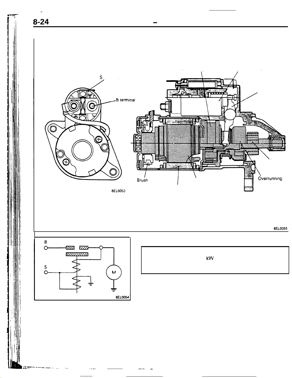
.-
8-24
STARTER MOTOR
ELECTRICAL
S
terminal
-
Engine Electrical
Reduction gear
!n
Magnetic switch
Shift lever
6ELOO53
Permanent magnet
I
SPECIFICATIONS
Type
................................
Nominal output
Rotating direction
............
Armature
........
hl
Reduction drive
1.2 kW
Clockwise
(viewed from pinion side)
Pinion gear
1
OverrunnIng
clutch
-
6EL0055
-.- .-
Page 77

IGNITION SYSTEM
ELECTRICAL - Engine Electrical
8-25
Sensors
I
Engine
control
unit
Power transfstor
1 I
Terminal for engine
speed detectton
h
hP
1
1
lgnltlon switch
I
lgnltion coil
C
To tachometer
Battery
6ELOO45
The ignition system is a two-coil ignition system that
supplies sufficient energy for ignition up to high
speeds. This engine does not have a distributor
since the engine control unit directly activates the
power transistor for ignition timing control.
The functions and controls of the engine control unit
and various sensors that control the ignition timing
are described in the next chapter, IGNITION CON-
TROL SYSTEM.
This ignition system has two power transistors and
two ignition coils. Power transistor “A” controls the
primary current of ignition coil “A” to activate the
spark plugs of the
Similarly, power transistor
“B” which activates the spark plugs of the
No.3
cylinders. In this way, spark plugs of two
cylinders are activated but actual ignition takes place
only in the single cylinder that is on its compression
stroke, because the other is on its exhaust stroke at
that time.
Power transistors “A” and “B” are activated by
signals from the engine control unit, that controls
which cylinder is fired at what time.
No.1
and
No.4
cylinders.
“B”
controls ignition coil
No.2
and
Page 78

8-26
ELECTRICAL
-
Engine Electrical
No.:
Capa &or
71
4
, tachometer
x
Cylinder
No. mark
Signal unit for
No. 3
6EL0025
6EL0057
To No. 1
spark plug
IGNITION COIL
Two compact ignition coils of a molded type featuring
outstanding ignition performance are used.
Being a two-coil type, the ignition coil has a unit to supply
signals for the tachometer.
Specifications
items
Primary coil resistance
Specifications
0.86 at
$2
20°C (68°F)
Secondary coil resistance
kR
12.1 at
20°C (68°F)
OC,
IB, G
To No. 4
spark plug
To
No. 3
spark plug
To No. 2
spark plug
6EL005t
POWER TRANSISTOR
The power transistor is driven by a signal from the engine
control unit and turns the priman/ current of the ignition coil on
and off.
Terminal symbol
G
IB,
I&
OG
oc2
Ground
Engine control unit
Engine control unit
Ignition coil terminal “2”
Ignition coil terminal “1”
External connection
SPARK PLUG
OC, IB, G IB,
OC:
I
Engine
Non-turbo
Type
BPR6ES-11
WZOEPR-11
RN9YC4
Gap
1.0-1.1
(.?39-.043 in.)
0.7-0.8
(.OZB-.031 in.)
mm
mm
I-
I
A
Page 79

-----.
_-- ___
ELECTRICAL
IGNITION TIMING CONTROL SYSTEM
Engtne
Air flow sensor
Intake air temp. sensor
Barometric pressure sensor
Engine coolant temp. sensor
control unit
-
Engine Electrical
Ignition switch
8-27
Battev
Idle position switch
Top dead center sensor
Crank angle sensor
Vehicle speed sensor
Ignition switch “ST” terminal
Detonation sensor for
turbo engine only
:+
;+
109
<
12
a”
The ignition control system uses the engine control
unit, that judges which cylinder is to be fired at what
time based on the signals coming from various
sensors. The engine control unit activates the
power transistors so that ignition occurs, taking into
4
Power
=
tranststor
_
1
Terminal for engine speed detection
Terminal for ignition,timing
and idle speed adjustment
“B”
I
P
Ignition coil
-
To tachometer
consideration the operating conditions of the
gine. The functions and controls of the engine
control unit are described in the following page.
The constructions and functions of the various
sensors are described in GROUP 14.
6FUoE.45
en-
Page 80

8-28
IGNITION TIMING CONTROL
ELECTRICAL- Engine Electrical
lgnitlon power
distribution control
(selection of power
transistor actlvatlon)
I’
Engine
control
unit
Reading
of
Control mode
I I I I I I
Input
signal
Control mode
dectsion data
Basic
energlzatlon
Power
tranststor “A” tranststor
The above block diagram shows the
fljnctions
of the
engine control unit for ignition timing control.
One feature is that the engine control unit provides
ignition power distribution control which is neces-
sary because this engine is without a distributor, as
has been described earlier. By activating two power
transistors alternately, the primary current of two
ignition coils, one for the No. 1 and No.4 cylinders
and one for the No. 2 and No, 3 cylinders is turned on
and
off.
thus causing the cylinders to fire in the
order of 1, 3, 4, 2.
For ignition timing control, -optimum ignition timing
.^--_
_.
-.
Power
“B”
6ELOO66
is determined by making preset corrections which
has been for engine coolant temperature, intake air
temperature an& other conditions of the ignition
advance angle that has been preset according to the
engine operating conditions. For vehicles with
bocharger have a knocking control that corrects tl
ignition advance angle according to the presence or
absence of knocking.
The engine control unit also controls the primary
current energization time in order to secure stable
ignition energy.
These controls are explained in detail below.
--. .-----
---- --- ___.
.-. ___.,.__
tur=_.
Page 81
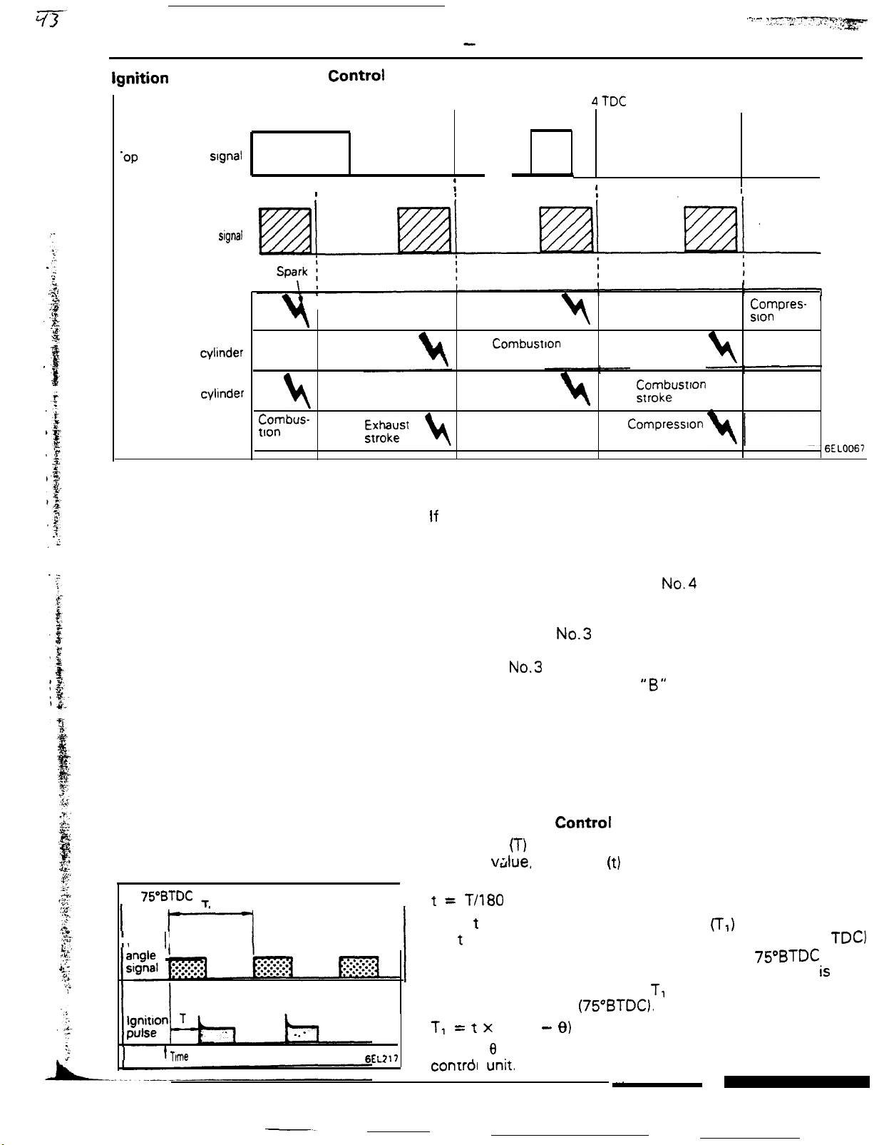
ELECTRICAL
Ignition Power Distribution Control
No. 1 TDC
I
‘op
dead center
Crank
signal
angle
signal
,
I
I I
-
No. 3 TDC
1
Engine Electrical
No 4TDC
\
I
I
.
,-s- ,-T,“~:~y.“‘
No 2 TDC
~...:tg==
8-29
No. 1 cylinder
No. 3 cyltnder
No. 4 cylinder
No. 2 cylinder tlon
,
Combus-
stroke
Combustion
stroke
Intake
stroke stroke
t\
Compression
Intake
stroke
Exhaust
stroke
Combustion Exhaust
t\
. stroke
Compression
stroke
intake
stroke
Intake
stroke
stroke
r$,mkbeustlon
Compresslon
stroke
Compresslon
stroke
Exhaust
stroke
6EL0067
The cylinder to be ignited is determined based on the top dead
center signal and the crank angle signal.
If
the top dead center signal has already been input to the
engine control unit when the crank angle signal is input, the
unit decides that the No. 1 cylinder (or No. 4) cylinder is on the
compression stroke and turns off power transistor “A” and
causes the No. 1 cylinder (and No.4 cylinder) to fire.
If the top dead center signal has not been input to the engine
control unit when the crank angle signal is input, the unit
decides that the No.3 cylinder (or No. 2) cylinder is on the
compression stroke and turns off power transistor “B” and
causes the No.3 cylinder (and No. 2 cylinder) to fire. In this way,
the power transistors “A” and
“B”
are turned off alternately for
ignition power distribution.
75”BTDC T
Crank
1
f Time
count start
6EL217
Ignition Timing Control
The period
on this
(T)
of the crank angle signal is measured and based
v&lue,
the time
(t)
taken for the crank to make a
revolution is determined.
= T/180
t
I
Once t is determined, the ignition timing
(T,)
is calculated using
the t value and the ignition advance angle (advance from
determined by the engine control unit, with the
75”BTDC
as a reference; then the primary current shut-off signal is Sent
to the power transistor when T, time has elapsed from the
count start position
= t x (75 -
Tl
where 8 is the ignition advance
_, ~4 -‘*
Lonrrol unlr.
(75“BTDC).
9)
angle calculated by the engine
TDC)
Signal
Page 82

8-30
Ignition Advance Angle Control
While
cranking
Fixed angle
(5”BTD.C)
Dunng
normal
Advance angle map value
according to engine speed
and intake
Durtng
ignition tlmmg adjustment
c
operatlon
air
volume
Fixed
angle
(5”BTDC)
coolant
4
temperature
ELECTRICAL
Engme
coolant
temperature
sensor
4
Engine
correction
-
Engine Electrical
Barometnc
pressure
sensor
i
Barometric
-
pressure
correctlon
__c
‘-Intake air 1
temperature
, sensor
+
Intake air
temperature 4
correctton
=ower
transistor
-$
s
To ignition
coil
6EL0066
The engine control unit has the ignition advance
angle value for all cylinder stroke intake air volumes
(engine load) and engine speeds stored in its
memory; this is called the basic ignition advance
angle. The control unit makes corrections in this
value according to the engine operating conditions
such as the engine coolant temperature, barometric
pressure (altitude) and intake air temperature to
obtain optimum advance angle for current engine
conditions. At the engine start and during ignition
timing adjustment, however, it is set to preset fixed
timing.
(1)
WHILE CRANKING
When cranking, the ignition advance angle is fixed at
5”BTDC
signal.
(2) DURING NORMAL OPERATION
Basic ignition advance angle:
Map values that have been preset for all cylinder
stroke intake air volumes (engine load) and engine
speeds.
in synchronization with the crank angle
Engine coolant temperature correction:
The engine coolant temperature sensor detects the
engine coolant temperature and when it is low, the
ignition timing is advanced to improve driveability.
Barometric pressure correction:
The barometric pressure sensor detects the
barometric pressure and determines the altitude.
When the pressure is low (i.e. when the vehicle is at
a high altitude), the ignition timing is advanced to
secure maximum driveability.
intake air temperature correction:
The intake air temperature sensor detects the intake
air temperature and when it is low, the ignition
timing is delayed to prevent knocking in cold
weather. When it is high, the timing is also delayed
to prevent of knocking.
(3)
DURING ADJUSTMENT OF IGNITION TIMING
When the terminal for ignition timing and idle speed
adjustment is shorted to ground, the ignition timing
is set at
angle signal, If the ignition timing does not agree
with the reference ignition timing of 5’BTDC, turn
the crank angle sensor to adjust the timing so that
the crank angle signal agrees with the reference
ignition timing. When the engine speed is approx-
imately 1,200 rpm or higher, however, the timing
advance is according to normal operation and
therefore this ignition timing adjustment is not
available.
5”BTDC
in synchronization with the crank
-
-
. .
-_ .--
-
1
Page 83

Knocking Control for Turbo Engine Only
Engine
Advance map
value
perarure correctton
- Barometric
correctton
coolant
pressure
tern.
Knockmg correcllon
Knockmg Level
- delermonmon - calculallon - derermmatlon
I
DelonaIlon
sensor
Knock
detemon
I
deIeclton
I
wbral+on
Fatlure
Y
Engine knocking is detected and the ignition timing
is controlled accordingly to prevent continued
knocking and to protect the engine.
When knocking is detected, the engine control unit
delays the ignition timing according to the signal
from the detonation sensor until the knocking is
eliminated (up to a maximum 12” in crank angle). In
the case of an open or short circuit of the detonation
sensor harness. the timing is delayed by a fixed
angle (approximately 8” in crank angle) to prevent
knocking.
lgnmon cod
primary currenr
v
Delay
angle
lgnmon tlmtng
I
6FUO565
If knocking continues, the advance angle map value
is corrected gradually in the delay direction.
In the absence of knocking, the map value is
corrected gradually in the advance direction. In this
way, optimum ignition timing is constantly controlled; this control is effective even when fuels of
different octane ratings are used.
This means that the engine is protected from
knocking damage even when the fuel is switched
from premium to regular or vice versa.
Energization Time Control
While
crankina
Synchronized
with crank angle
sensor signal
c
During normal operation
Map value
responding to
battery voltage
cor- Energizatlon
-
is clipped at 75% of
ignition interval
I
In order to obtain stable ignition energy, the
gization time of the ignition coil primary current is
controlled as to keep current at a constant value
when the primary current is shut off.
(1)
DURING NORMAL OPERATION
Basic energization time
:
The increase of the ignition coil primary current
changes with the battery voltage. Therefore, the
energization time is so controlled that the primary
current at time of ignition becomes
6A.
energization time is so set that it is longer when the
battery voltage is low and is shorter when the
ener-
The basic
time
6FUO548
Energization time clip:
The new two-coil ignition system has its ignition
interval doubled when compared to the convention-
al single
coil
type, allowing a longer clip time. As a
result, a long energization time is secured for
sufficient ignition energy even during high speed
operation.
(2)
WHILE CRANKING
When cranking, the ignition coil is energized in
synchronization with the crank angle signal.
-
Page 84

8-32
ELECTRICAL - Theft-alarm System
THEFT-ALARM SYSTEM
When the theft-alarm system has been armed by a
fixed sequence for locking the doors with the key or
without the key, if thereafter a door, the rear hatch
or the hood is opened in an unauthorized way. the
horn will sound intermittently for period of approximately three minutes, and. at the same time, the
headlights will flash on and off, thus providing
audible and visual warning. signals.
Starter
ECU
I
NOOIAAA
Security
Key-reminder
switch
lig
Furthermore, the starter circuit is interrupted in
a way that the engine cannot be started, if
ignition key is not used. Note that this system is
controlled by the electronic control unit (ECU).
This ECU includes an independent microcomputer
for the exclusive use of the theft-alarm system. This
microcomputer arms, disarms, activates and deactivate the alarm system.
The system is composed of the components de-
scribed below.
Liftgate unlock switch
!
/
SI
‘L
Horn
OPERATION
*.
.u
Driver opens door with the key
0
Normal starting
i
‘11
. .
-I
Door key cylinder
”
daytime running light relay
About 20 seconds after all doors are closed
and locked. the rear hatch is closed. and the
hood is closed + SYSTEM ARMED
A door rear hatch or hood is broken
Headlights
I
flicker
I
SYSTEM DISARMED
-1
*D
ALARM
ACT,“ATED
* n
.
l .
I
Driver unlocks a door
or rear hatch with the
key.
0
J-
Engine is disabled to start.
-
ALARM DEACTIVATED
(SYSTEM DISARMED)
Page 85

ELECTRICAL - Theft-alarm System
ARMING THE SYSTEM
After the following procedures have been completed, the SECURITY light illuminates for about 20 seconds,
and when illumination stops, the system is armed.
(1) Pull out the ignition key from the key cylinder.
(2) Open a door. (The other door is closed.)
(3) Lock the door with the key or the
(The central door locking system will then function to lock all doors.)
NOTE
(1) The system is set regardless of whether the hood and liftgate are open or
soon as the light goes out.
(2) Even after the system has been armed, if the key is used to open the liftgate, the system will not be
activated; when the liftgate is then
DISARMING THE SYSTEM
(1) The system will be disarmed if the key is used to unlock a door.
(2) If the system is armed while the driver is still in the vehicle, the system can be disarmed by inserting the
ignition key and turning it to the ACC or ON position.
(3) If the door lock is unlocked while closing the door or the door is ajar.
(4) If the door is unfastened while the SECURITY light illuminates.
ACTIVATING THE ALARM
(1) if an attempt is made to open a door, the liftgate or the hood, without using the key, while the system is
armed, the horn will sound intermittently and the headlights will flash on and off for approximately
minutes.
Furthermore, the starter circuit is interrupted at this time also, making starting of the engine impossible.
(2) if a further attempt at *forcible entry is made after the first three-minute alarm has finished, the
three-minute alarm will be activated again.
DEACTIVATING THE ALARM
(1) To deactivate the alarm, insert the key into the door’s key cylinder and turn the key.
(2) The alarm is deactivated and the system is disarmed when the iiftgate is unlocked with the key.
CHECKING THE SYSTEM OPERATION
The activation/operation of the system can be checked by following the steps below.
(1) Turn the ignition key to the ON position and then use the power-window switch to fully open the window
at the driver’s seat side.
(2) Turn the ignition key to the LOCK position and then remove the key from the ignition.
(3) Open only the driver’s door, and close all the other doors, as well as the hood and the rear hatch.
(4) Lock the driver’s door by the key or the
(5) All doors will then be
to be sure that illumination stops in about 20 seconds.
(6) After about two seconds have passed after the SECURITY light illumination stopped, reach through the
window of the driver’s door, pull up the lock lever to unlock the door, and then open the door.
(7) Check to be sure that, when the door is opened, the horn starts sounding and the headlights flash on and
Off.
(8) To stop the alarm, insert the key into the door’s key cylinder and turn the key.
locked,
and the SECURITY light (within the combination meter) will illuminate; check
keyless-locking
closed,
moreover, the system
keyless-locking
method.
method.
closed,
will
be armed.
and is armed as
8-33
three,
!?iEeck
remote liftgate release lever (or the hood release lever),
alarm is activated by the opening of a door, or after the finish of the first three-minute alarm.
the alarm for the opening of the liftgate or hood open the liftgate (or the hood) by using the
located
at the driver’s seat side either before the
Page 86

ENGINE
CONTENTS
.._. - -II.- -.....
BASE ENGINE
Connecting Rod
Crankshaft
Crankshaft Pulley
Cylinder Block
Cylinder Head
Main Bearing Caps
Piston
Piston Rings
Rocker Cover
Silent Shaft System
Timing Belt Train
Valve Mechanism
.................
............................................................
.................................................... 10
................................................
............................................
...................................
........................................
................................................
................................................
........................................
................................................
....................................
............................................
........................................
11
11
12
11
10
7
9
7
MOUNTS
8
12
17
13
GENERAL INFORMATION
Engine Cut-away View
Major Specifications
Technical
LUBRICATION SYSTEM
Specifications
Construction Diagram
Features
................................................
..................................................
....................................
........................................
............................
................................
................................
..............
................................
20
20
21
21
2
4
2
3
I
-
_.
_--
-- ___._ ._- _._._ -.
^
_..
Page 87

=--Y
jl
9-2
_. ---“.
_
_ _ ._
+_LI_y_---
-
ENGINE
..-..
-
General Information
1 /
i "
GENERAL INFORMATION
MAJOR
Items
Number and arrangement of cylinder
Cylinder bore x stroke
Total displacement
Compression ratio
Combustion chamber
Valve mechanism
Number of valve
Intake
Exhaust
Valve timing
Intake Open/Close
Exhaust Open/Close
Lubrication
Oil pump
Fuel system
Supercharger
Cooling system
Water pump
Alternator
Starter motor
Ignition system
Exhaust gas
Catalytic converter
Crankcase ventilation
Evaporative emission
SPEClFlCATiONS
mm
(in.)
cc
(cu.in.1
recirculation system
system
control system
Non-Turbo engine
4 in-line, longitudinal
85 x 88 (3.346 x 3.465)
1997 (121.9)
9.0
Pentroof
Double overhead camshaft
(DOHC)
8
8
26
56BBDUS”ATDC
Pressure feed-full flow filtration
Gear type
Electronic control
injection
Liquid cooled-forced circulation
Impeller type Impeller type
AC generator with a built-in
voltage regulator
Planetary gear reduction drive
type
Two-coil type, electronic control
ignition ignition
Conventional type: For Federal
and Canada
Electronical
For California For California
Monolithic type,
installation installation
Closed type Closed type
Charcoal canister type
type
“BTDU46”ABDC
control type:
under-floor
multipoint
fuel
Turbo engine
4 in-line, longitudinal
85 x 88 (3.346 x 3.465)
1997
(121.7)
7.8
Pentroof
Double overhead camshaft
(DOHC)
8
8
21”BTDC/Sl”ABDC
55”BBDUS”ATDC
Pressure feed-full flow filtration
Gear type
Electronic control multipoint fuel
injection
Turbo type
Liquid cooled-forced circulation
AC generator with a built-in
voltage regulator
Planetary gear reduction drive
Two-coil type, electronic control
Conventional type: For Federal
and Canada
Electronical
Monolithic type, under-floor
Charcoal canister type
type
Row- -
-
control type:
I
Page 88

q7
--
_-.-
ENGINE - General Information
TECHNICAL FEATURES
HIGH PERFORMANCE AND . .
FUEL ECONOMY
LOW VIBRATION AND
LOW NOISE
SERVICEABILITY . . . . . . . . . . . . . . . . . . . . . . . . . . . . . . . . . . . . .
.._..............
. . . . . .
..I.................
1.
The
DOHC 16-valve
efficiency.
2.
The rocker arm is of the roller-type-cam-follower design which
minimizes friction loss.
3. The combustion chamber is of the pentroof type with a squish
area that offers outstanding combustion efficiency.
4. The multipoint fuel injection system is electronically
controlled.
5. The intake manifold is the inertia supercharging type which
improves intake efficiency and the dual-type exhaust manifold
offers good exhaust efficiency.
6. The two-coil type electronic control ignition system ensures
good ignition performance.
1.
The hydraulic lash adjuster, together with the roller rocker arm,
contributes to reduced operating noise of the valve mechanism.
2. A cogged type belt is used to drive the camshaft.
3. The auto tensioner maintains the optimum timing belt tension.
4. The torsional damper reduces twisting vibration in the crankshaft’
to a minimum.
5. The silent shaft system reduces engine vibration and rolling
moment to a minimum
1. The self-diagnosis system makes troubleshooting easier.
2. The lash adjuster eliminates the need for valve clearance
adjustment.
3. The auto tensioner eliminates the need for timing belt
tension adjustment.
engine ensures excellent intake and exhaust
9-3
I
’
-.--
..-.
--.-
Page 89
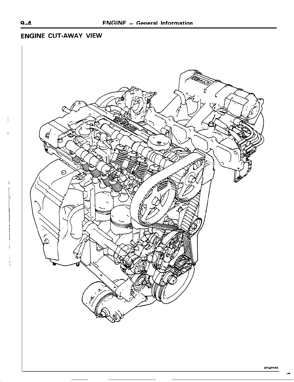
.._..
.-
._
_
_
---
.__._._.....-.
.,
__.
.-.-.
Page 90

10 -
--------
-.
ENGINE
-
General information
9-5
Lb..
- -. __
---
6EN0362
_
Page 91
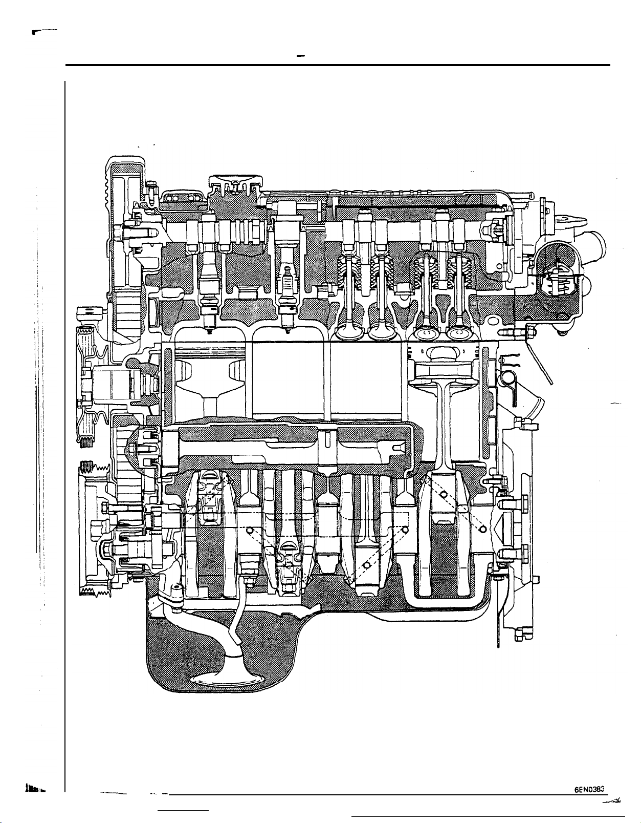
9-6
ENGINE
-
General Information
.--
--
-.. _
6EN0363
-44
Page 92
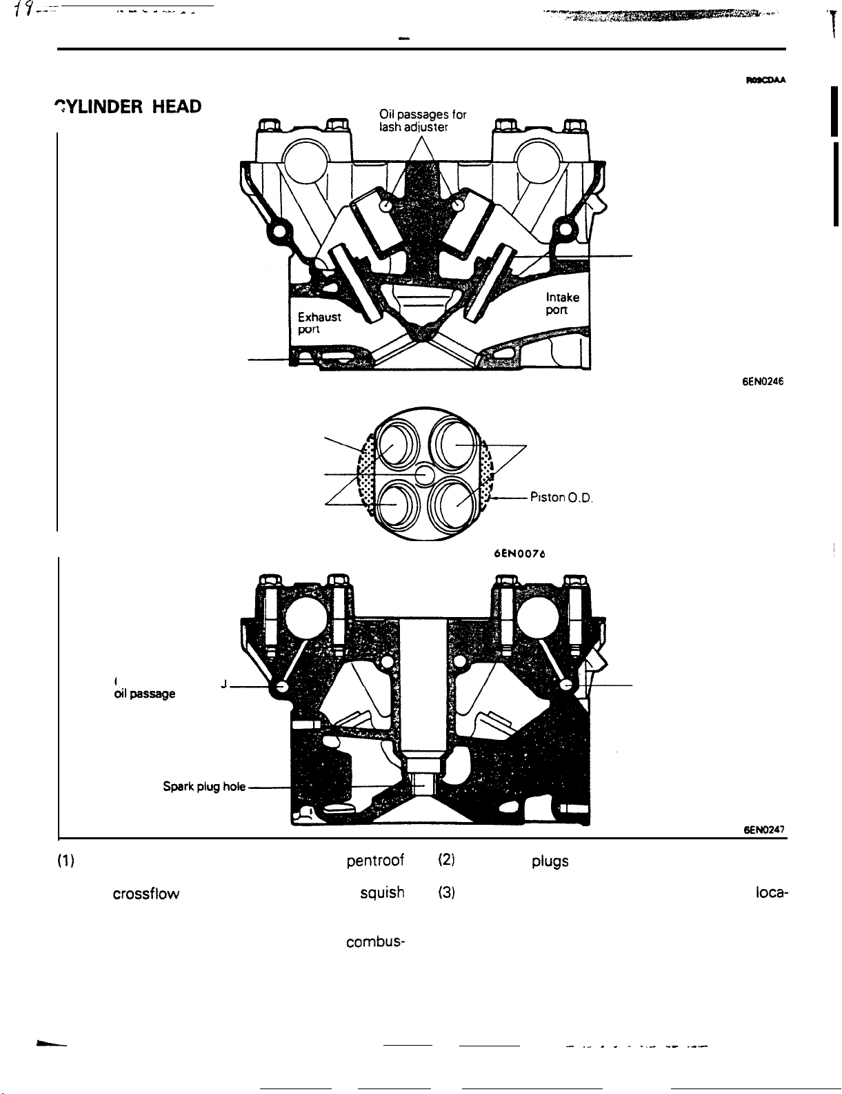
s’ y _._--
--
,_ - k -
..-_ _
_
BASE ENGINE
Valve se
-
ENGINE
at
Base Engine
Valve guide
9-7
6ENO246
I
Camshaft lubricating
Squish area
Spark plug hole
Exhaust port
intake port
Piston O.D.
6EN0076
Camshaft lubricating
oil passage
6ENO247
(1)
The combustion chamber is of the pentroof
The spark
plugs
are located at the center of the
(2)
type. The two intake and two exhaust ports are combustion chambers.
in a crossflow arrangement. There is a
area provided in the combustion chamber,
squish
(3)
The camshaft bearings are placed at six
tions on the intake side, and six on the exhaust
which promotes turbulence, further mixing of side (see next page illustration). The thrust load
the air-fuel mixture, and more efficient
tion.
combus-
of each camshaft is transmitted to the No. 1
bearing.
- ._ _ _ - -,- -- .---
loca-
Page 93

9-8
ENGINE - Base Engine
Ri
Camshaft
:kets -
sproc
side
ROCKER COVER
0
cy
CL
Bearing cap No.
R:
Exhaust side
L: intake
P
Q
j
stde
No. 5
No.4
bd
no. 1
No.
6
\-
intake side
6EN0077
Rocker cover
erection
plug cable is installed.
that the spark
6EN0378
Installed inside the rocker cover is the breather plate. The
blowby gas passes through the space between the breather
plate and rocker cover and is drawn through the positive-
crankcase-ventilation valve to the intake manifold. As a result,
fresh air is drawn to the engine cylinders.
From air
intake
hose
Breather plate
To intake
manifold
Positive crankcase
ventilation
Viewed from bottom
of rocker cover
l
C$
valve
Blow-by gas
Fresh air
Rocker cover
6EN0384
-
Page 94

CYLINDER BLOCK
Engine oil main gallery
Silent shaft bearing,
rear
shaft bearing,
Silent
front
-
ENGINE
Coolant inlet
\
A
taw
Base Engine
A
Engine oil to
cylinder
head
9-9
engine only)
Silenishaft
rear
(1)
bearing.
There is an oil jet provided for each cylinder just under the
main gallery of the cylinder block. When the pressure of oil
from the main gallery exceeds 200
kPa
(2 kg/cm’, 28 psi),
the oil pushes open the check valve, spurting over the
inside of the piston, thus cooling it. (Turbo engines only)
(2)
The water jacket is the
Siamese
type.
6EN0246
Page 95

9-10
PISTON
For non-turbo engine
Pin
;nterline y FPiston ceyerline
ldentificatlon
ENGINE
For
turbo engine
-
Base Engine
Steel strut
6EN0124
I
j
(1) The piston is the autothermic type with steel
.
struts cast into it.
(2) The depth of the trough in pistonhead varies for
the non-turbo and turbo engines.
6EN0125
6EN0249
,
(3)
The piston pin is of the semi-floating type, press-fitted to
the connecting rod and rotates freely in the piston.
Piston
pin
Connecting
rod?\
i
~Piston
6EN0250
No. 1 piston ring
.,YM,,
No.
For turbo engine
3
fiFNflR7
PISTON RINGS
(1)
The No. 1 piston ring IS of the barrel type.
(2)
The No. 2 piston ring is of the taper type. The surface in
contact with the cylinder wall is coated with hard chrome
plating.
(3)
The oil ring is of the three piece type, consisting of two
rails and an expander.
-
sL
Page 96

ENGINE
-
Base Engine
CONNECTING ROD
(1)
The same connecting rod is used as that used in the
SOHC engine.
(2)
The oil jet provided in the shoulder of the connecting rod is
used to lubricate the cylinder wall.
(3) The big-end bearing is the kelmet metal with metal backing.
9-11
4663
7
Oil jet
Front mark
6ENOO6l
CRANKSHAFT
(1) The crankshaft is supported by the five main bearings.
(2) The oil passages drilled to the crankpins permit the flow of
lubricating oil from the main bearing to the connecting rod
bearing.
(3) The crankshaft has been subjected to special surface
treatment. Therefore, do not grind it for reuse.
(4) The main bearing is an aluminum alloy with a backing of
another metal. The center bearing is provided with flanges
to receive the thrust load of the crankshaft.
1
I
No. 5
Oil passage
6EN0089
1
MAIN BEARING CAPS
The No. 1 and No. 2 main bearing caps are joined, as are the
No. 4 and No. 5 main bearing caps, by means of a beam to
minimize vibration of the bearing saddles and to enhance
rigidity of the crankshaft support.
Oil passage
6ENOOQO
--
.--.
_
A
Page 97

9-12
CRANKSHAFT PULLEY
ENGINE
- Base Engine
Drives the water
pump and alternator
Hub-
Pulley
-
Drives the air
conditioner
compressor
Fin
Rubber
6EMI252
(1) The crankshaft pulley not only drives the water
pump and alternator, but also functions as a
torsional damper to reduce torsional vibration of
the crankshaft.
Timing belt cover
6EN0145
(2) There are fins provided at the back of the pulley
that ventilate the inside of the timing belt cover:
when the pulley rotates, they draw air out of the._
timing belt cover.
SILENT SHAFT
SYSTEM
Forward
@
Center of crankshaft
/
Silent shaft --
I
6ENl32
t uluv -
The silent shaft system counteracts the secondary reducing the vibration and noise generated by the
exciting moment in the engine’s vertical direction as engine. The system is exactly the same as that used
well as the rolling moment, thereby drastically
--
-----_
---.--- __.----_. _... ,.
in the conventional
4G63-SOHC
engine.
Page 98

VALVE MECHANISM
!
ENGINE - Base Engine
Rocker arm
9-13
Exhaust
camshaf
...............
...............
..............................
..............................
..........................
.......................
.......................
.......................
.......................
..........
..........
.........
.........
..........
.........
..........
Ift
Exhaust valve
(1)
The
valve
mechanism is the DOHC
16-valve
system.
.(2)
The rocker arm with a roller follower. i.e., the
roller rocker arm, is used that reduces drastically
the friction loss of the valve train.
(3)
The hydraulic type lash adjusters automatically
adjust the valve clearance, minimizing noise
bENO
Intake valve
6ENOlOO
generated by the valve train. They also eliminate
the need for valve clearance adjustment.
(4)
The valve springs, whose cross section is
contribute to the enhanced spring load. This in
turn ensures that the valves operate properly.
especially at high speed.
oval.
-
.---..
Page 99

ENGINE
ROCKER ARM
(1) The cam follower of the rocker arm is a roller with nea,.,-
- Base Engine
bearings.
,I$
v
Needle bearing
- I
-
‘Roller
6ENOlOI
(2) A jet of oil spurts onto the contact area between the cam
and roller from an oil jet located on the fulcrum side of the
rocker arm.
(3)
Since the roller rotates as the cam rotates, friction loss is
drastically reduced as compared with the conventional
slipper type.
6EN025-4
(4) Due to the construction of the roller rocker arm, the valve
train driving torque is reduced to about half that of the
conventional slipper type, which is equivalent to, or
2-valve SOHC
slipper type
compares favorably with, the
2-valve
SOHC slipper type. All
these factors contribute to enhanced engine performa
and fuel economy.
LASH ADJUSTER
,
The hydraulic lash adjuster is of the end pivot type. It eliminates
O-valve
9
0
DOHC roller type
2.500
Engine speed
rpm
5.000
6ENOl
1
o(
the need for adjustment of the valve clearance. There are four
lash adjusters provided for each cylinder, 16 in all.
Oil passage ,
Lash adjuster
Cylinder head
Valve
-
‘-
Rocker
E
-
-
Camshaft
I-
an
IF=
Ir
Reservoir chamber
-
6E NO255
6EN0256
Page 100

5-j
Operation of the Lash Adjuster
When the valve starts opening
ENGINE- Base Engine
During the valve opening stroke
9-15
/f-b
When the valve
the opening stroke
coiqpletes
6EN0254
n
6EN0257
(1)
Before the valve starts opening:
--
No external load is applied to the
plunger,
causing the plunger to be pushed UP
plunger spring, maintaining zero clearance.
.(2)
When the valve starts opening:
When the cam pushes the rocker arm, the
the high-pressure chamber immediately is held
pressed against the seat by the hydraulic pressure. fully closing the high-pressure chamber. AS
the check ball closes, the pressure in the
high-pressure chamber surges causing the plunger to support the load from rocker arm, which
allows the valve to start
.
- -__
ooenino.
thus
by the
ball
in
6EN0256
(3)
During the valve opening stroke:
A very small amount of oil leaks through the
clearance between the lash adjuster body and
plunger.
(4)
When the valve completes its opening stroke:
There is no external load being applied to the
plunger as the valve closes, causing the plunger
to be pushed up by the plunger spring. This
causes the pressure in the high-pressure cham-
ber to be lowered, which pushes the check ball
open. The oil which has leaked is replaced in the
high-pressure chamber from the reservoir chamber.
-
 Loading...