

Page 1

K6860899 – WI-FI ROUTER
Click on the desired vehicle to take you directly to the vehicle specific
instructions.
RAM – REGULAR CAB
RAM – QUAD/CREW CAB
300/CHARGER/CHALLENGER
CALIBER
COMPASS
DAKOTA
GRAND CHEROKEE
JOURNEY
MINIVAN
NITRO/LIBERTY
PATRIOT
PT CRUISER
SEBRING SEDAN/AVENGER
SPRINTER
WRANGLER
Oct 16, 2009 K6860899 Rev. 1
Page 2
WIFIROUTER,REGULARCAB
PRINT THIS VEHICLE
INDEX
DODGERAMREGULARCAB
PROCEDURESTEPS:
NOTE:Usingatestlight,verifythecigarettelighteroutletbeingusedisignitionswitched.Powermustnotbe
suppliedwiththeignitionintheOFFposition.
1.Disconnectandisolatethebatterynegativecable.
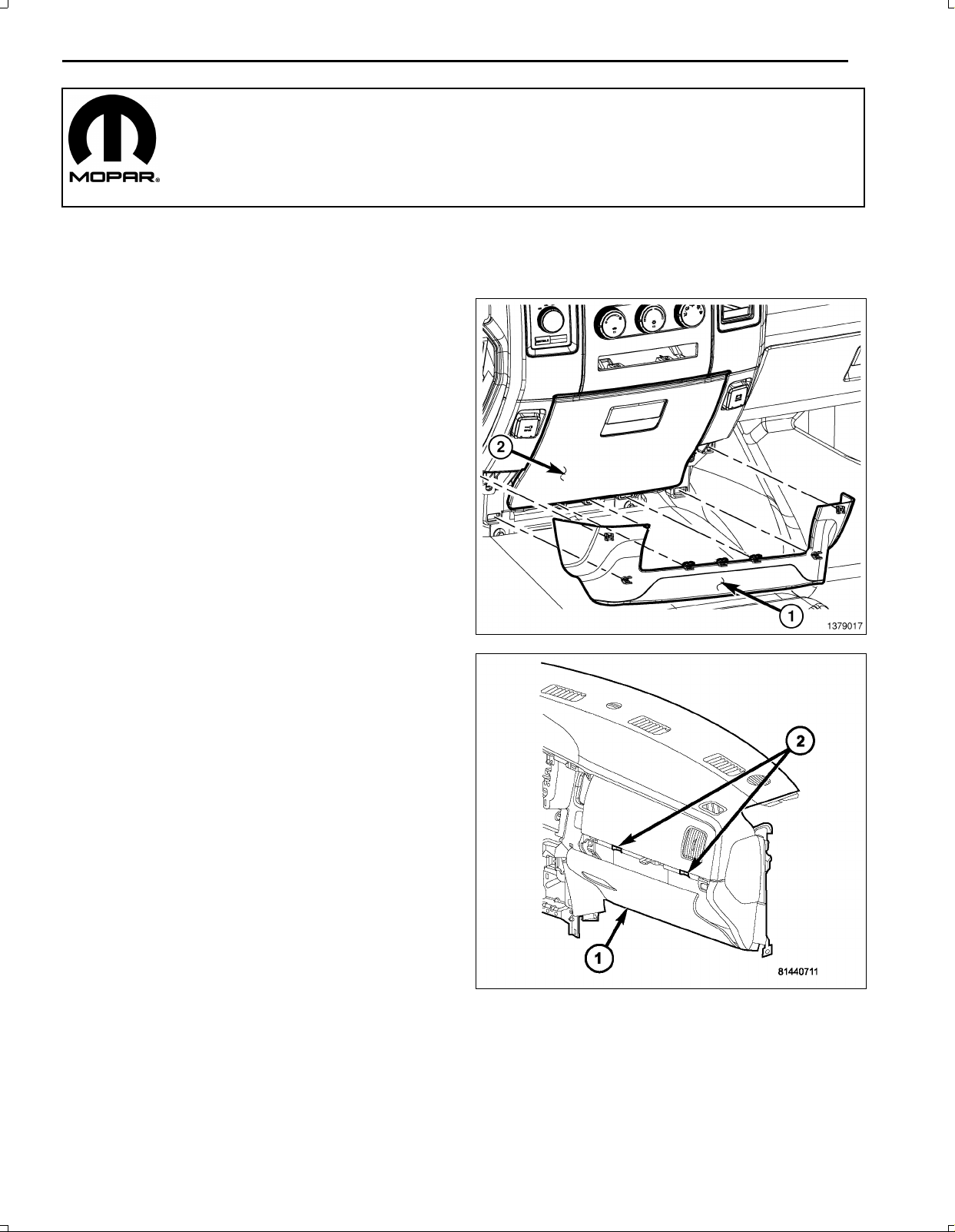
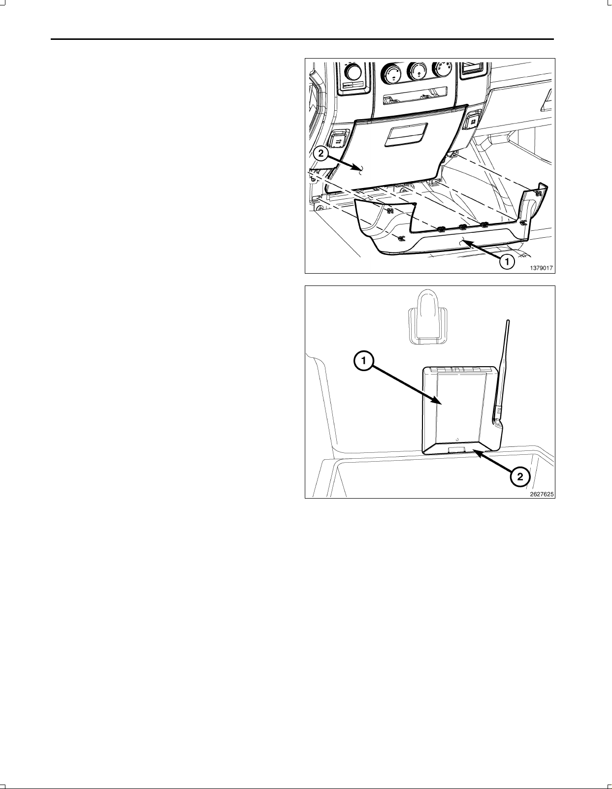
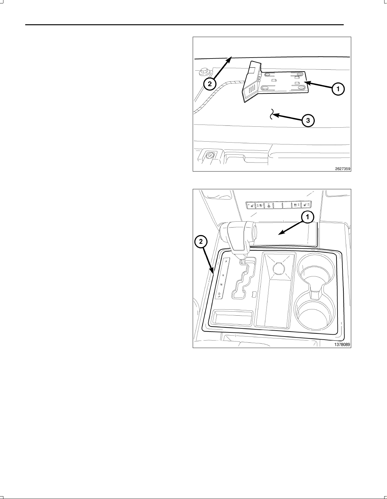
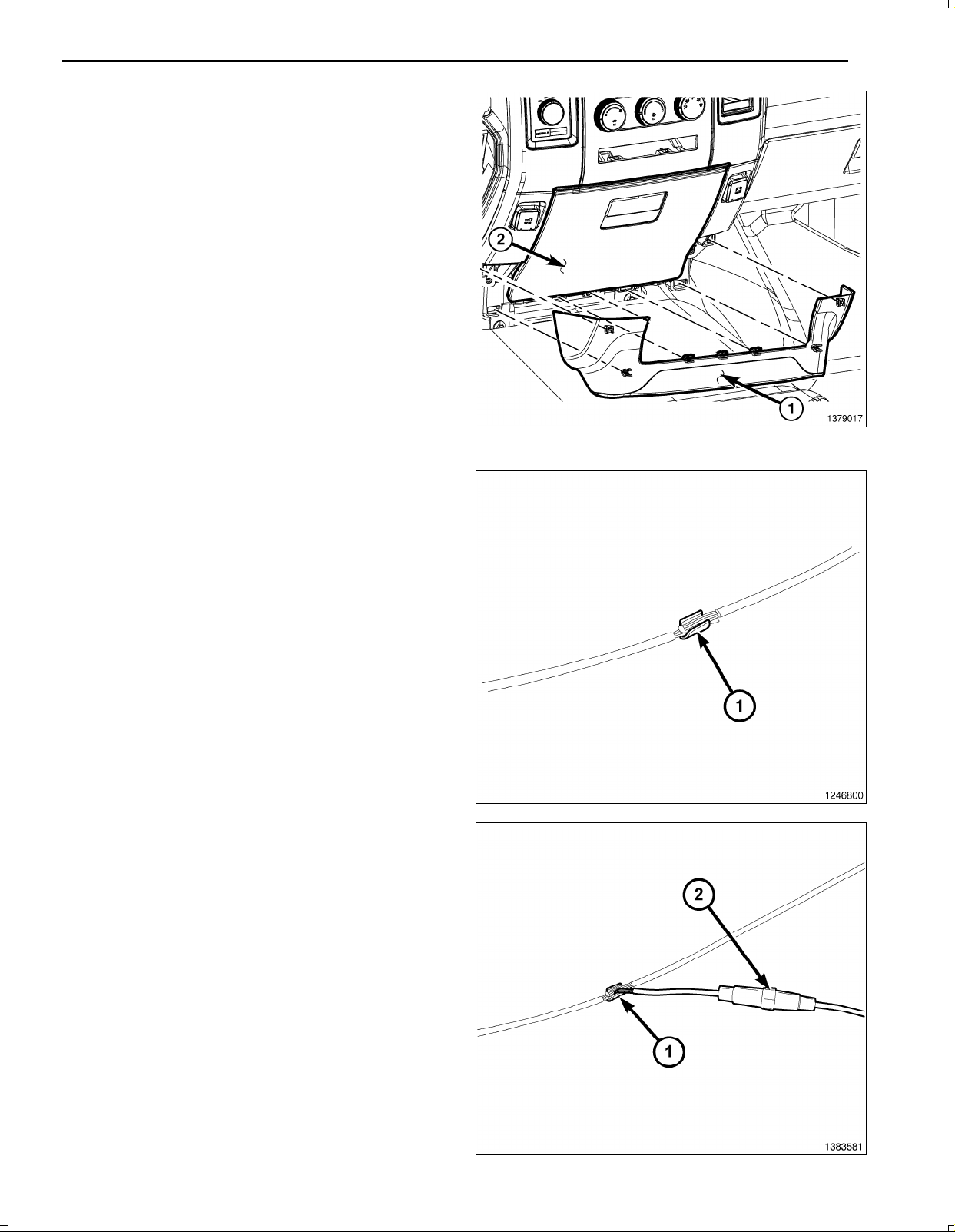
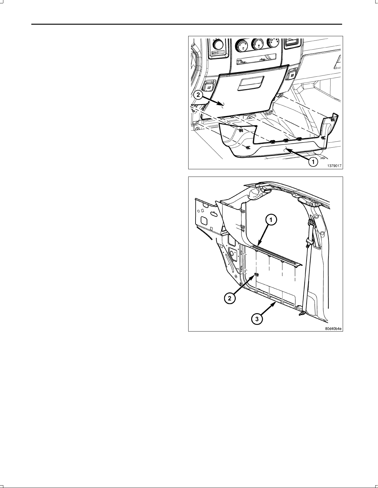
2.UsingatrimstickC4755orequivalent,disengagethe
retainingtabsandremovethelowerbezelpanel(1).
3.Removethetwolowerscrewssecuringthecupholder
totheIP .
4.Foldthecupholderdownandlowerthecupholder(2)
closeoutpanelbydepressingthetabatthetopofthe
panel.
5.Removethetwoscrewsfrombehindthecloseoutand
removethecupholder.
6.UsingtrimstickC4755orequivalent,disengagethe
retainingtabsanddisconnectthepoweroutletelectri
calconnectors.
7.RemovethelowerIPsurroundfromthevehicle.
1
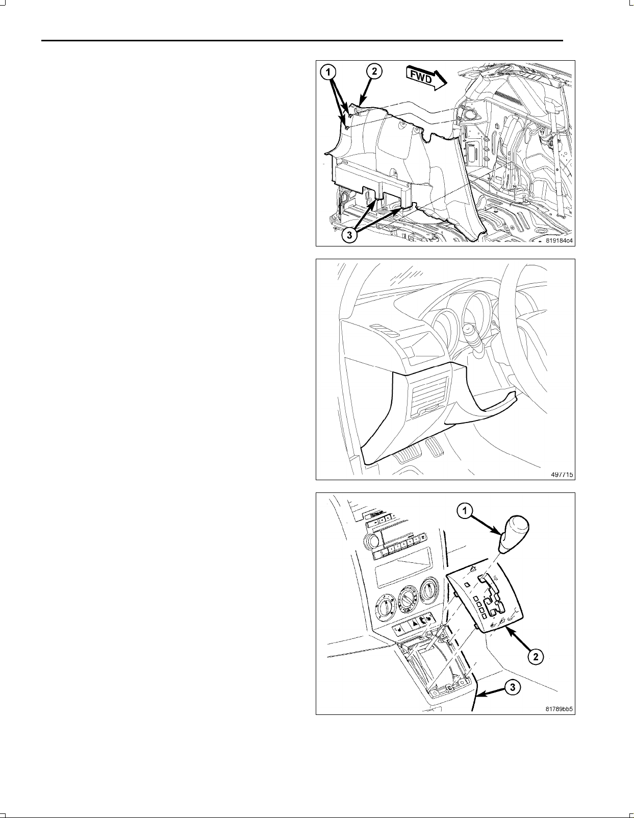
8.Opentheglovebox(1).
9.Releasethetwogloveboxstops(2)andlowerthe
gloveboxdownwardpastthestops.
10.Disengagethegloveboxhingesfromtheinstrument
panelandremovetheglovebox.
Oct16,2009K6860899Rev .1
Page 3
2
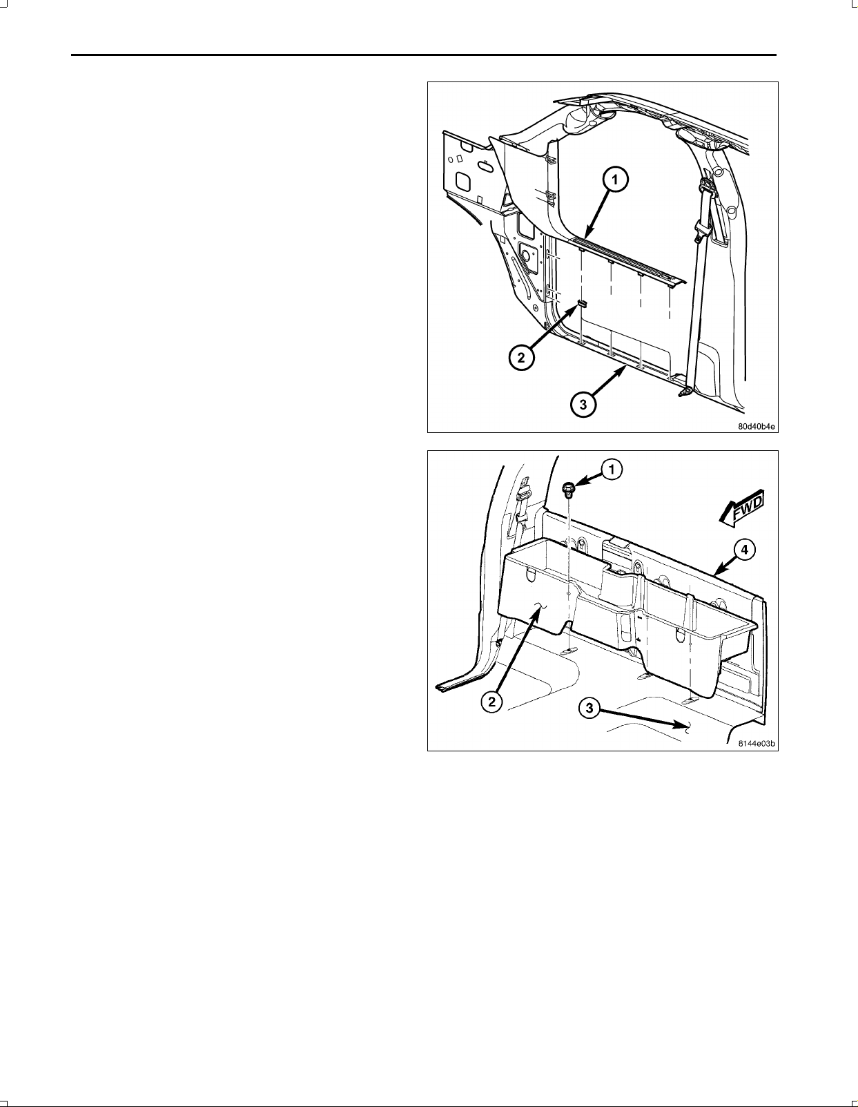
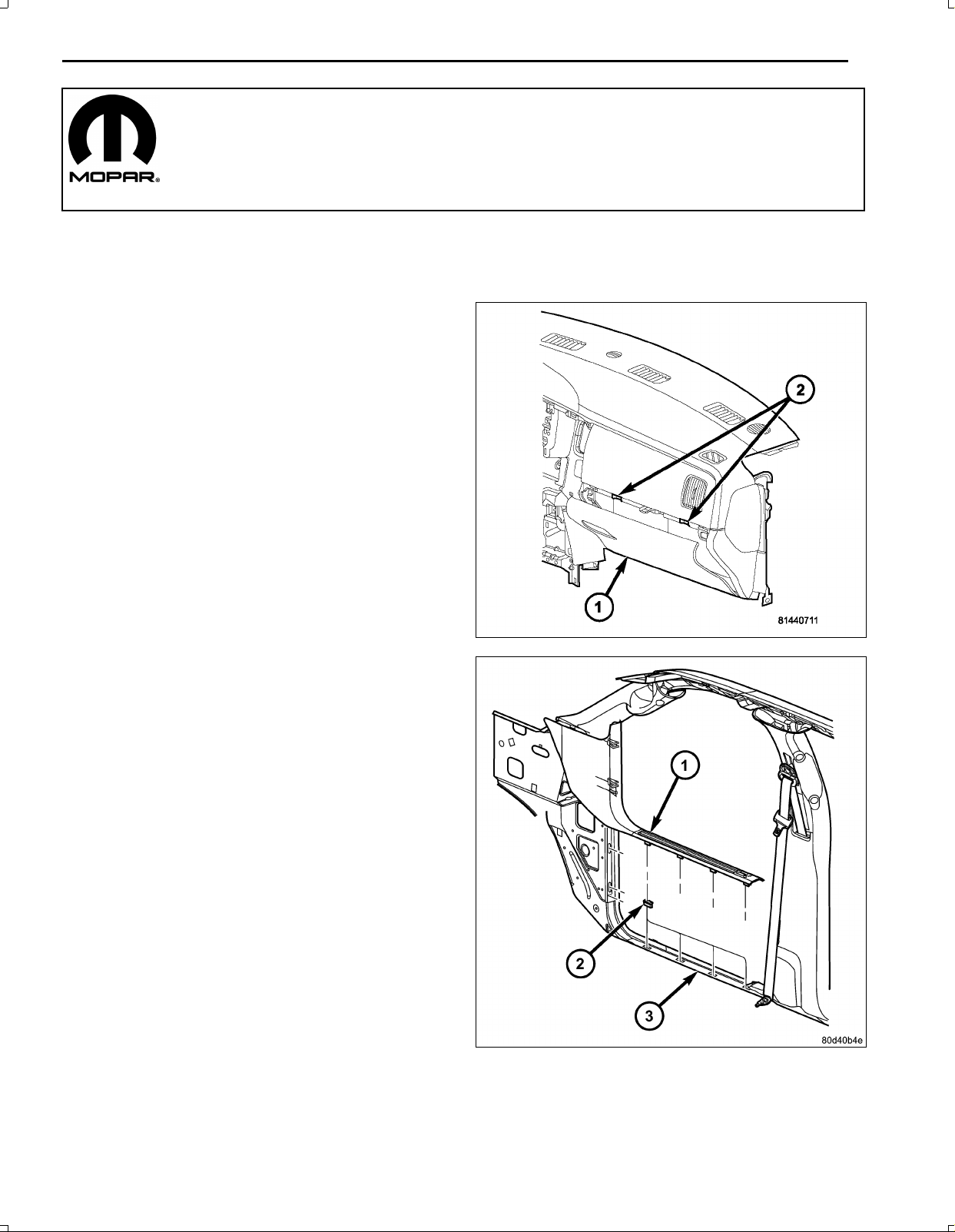
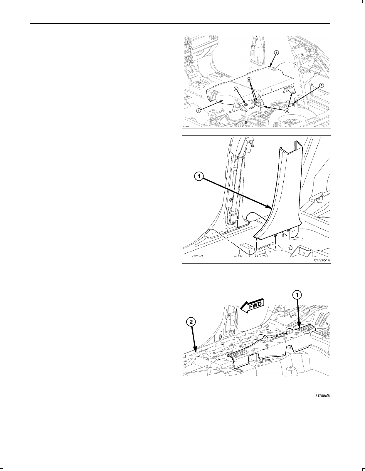
11.UsingatrimstickC4755orequivalent,disengagethe
retainingtabsofthecowltrimpanel(1)fromthere
tainerclips(2)inthedoorsill(3).
12.Pullthecowltrimpanelrearwardandremoveitfrom
thevehicle.
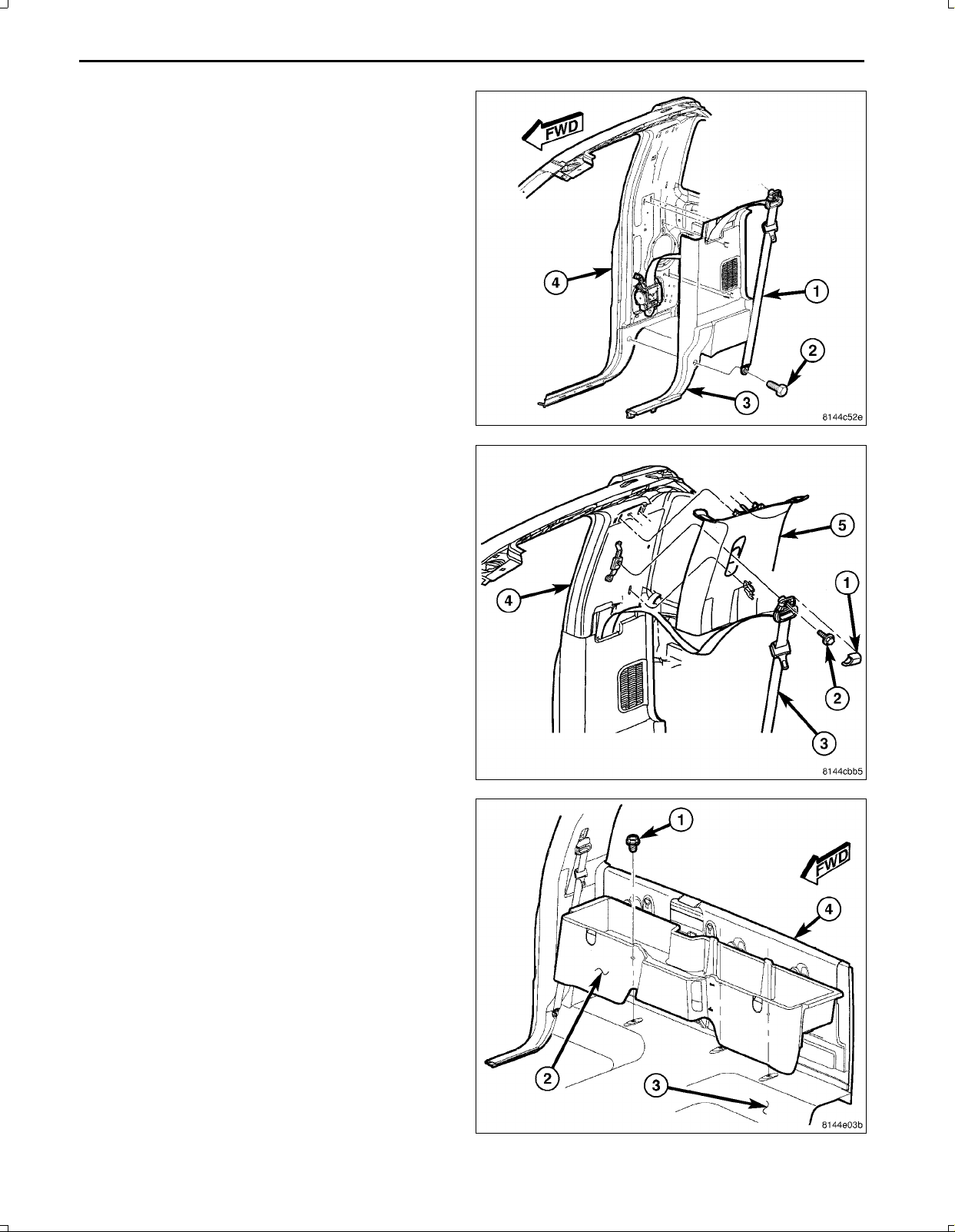
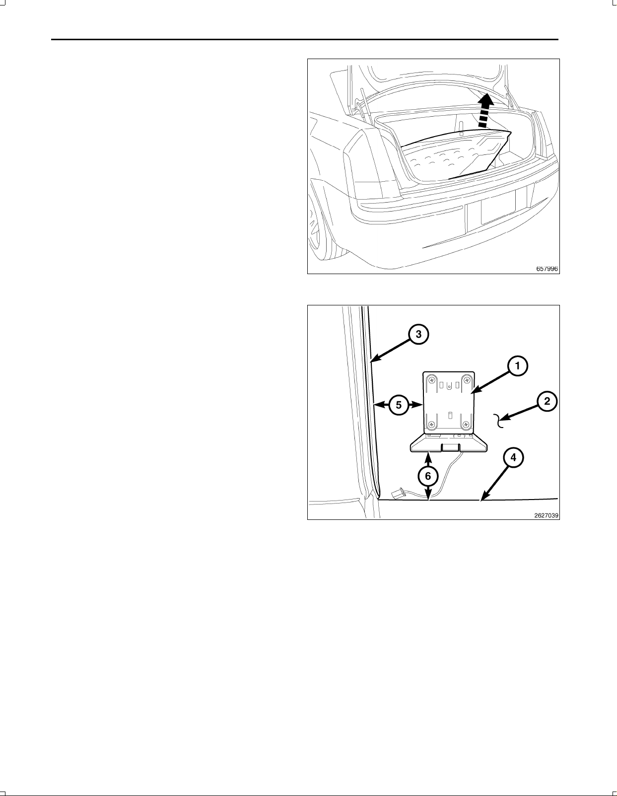
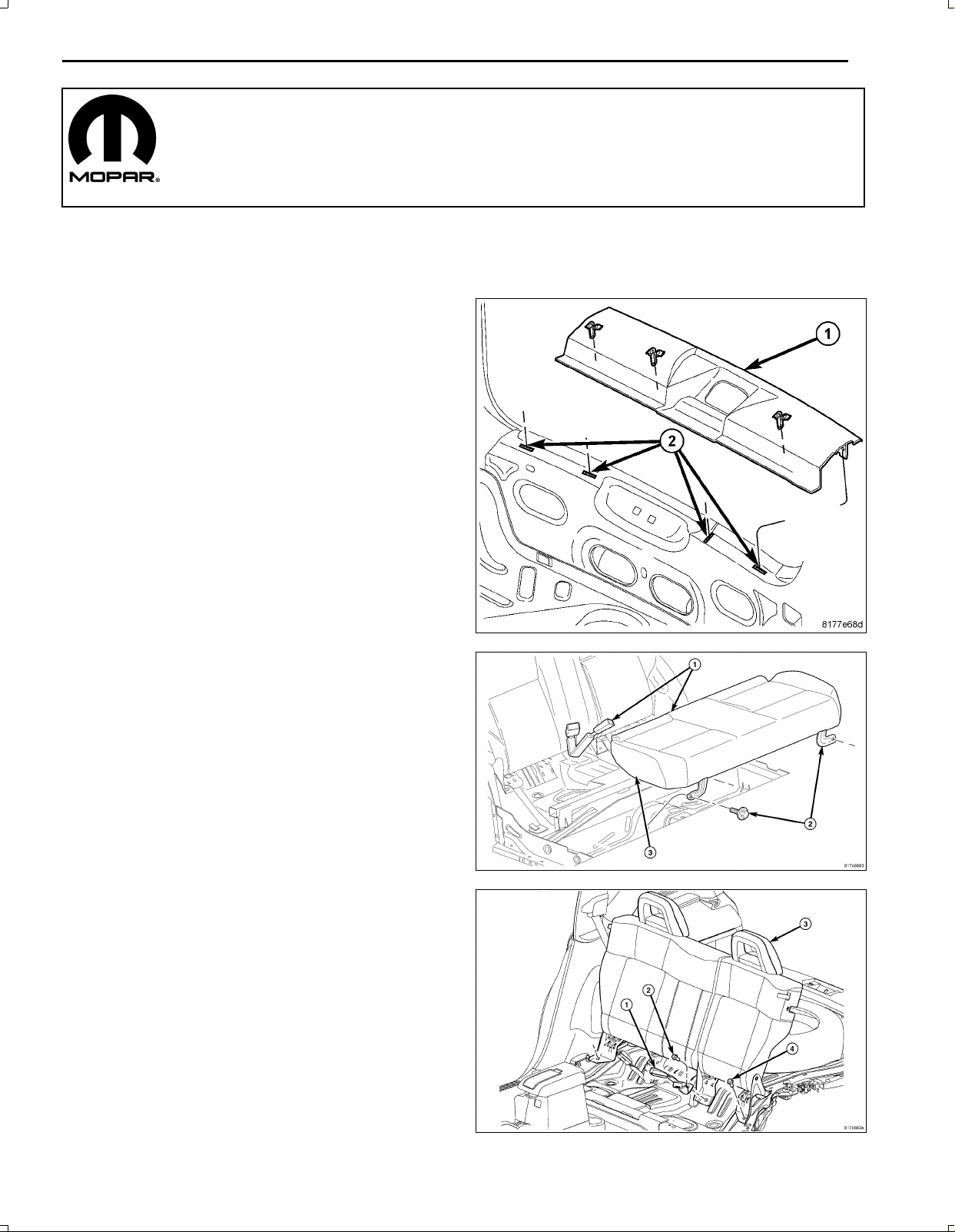
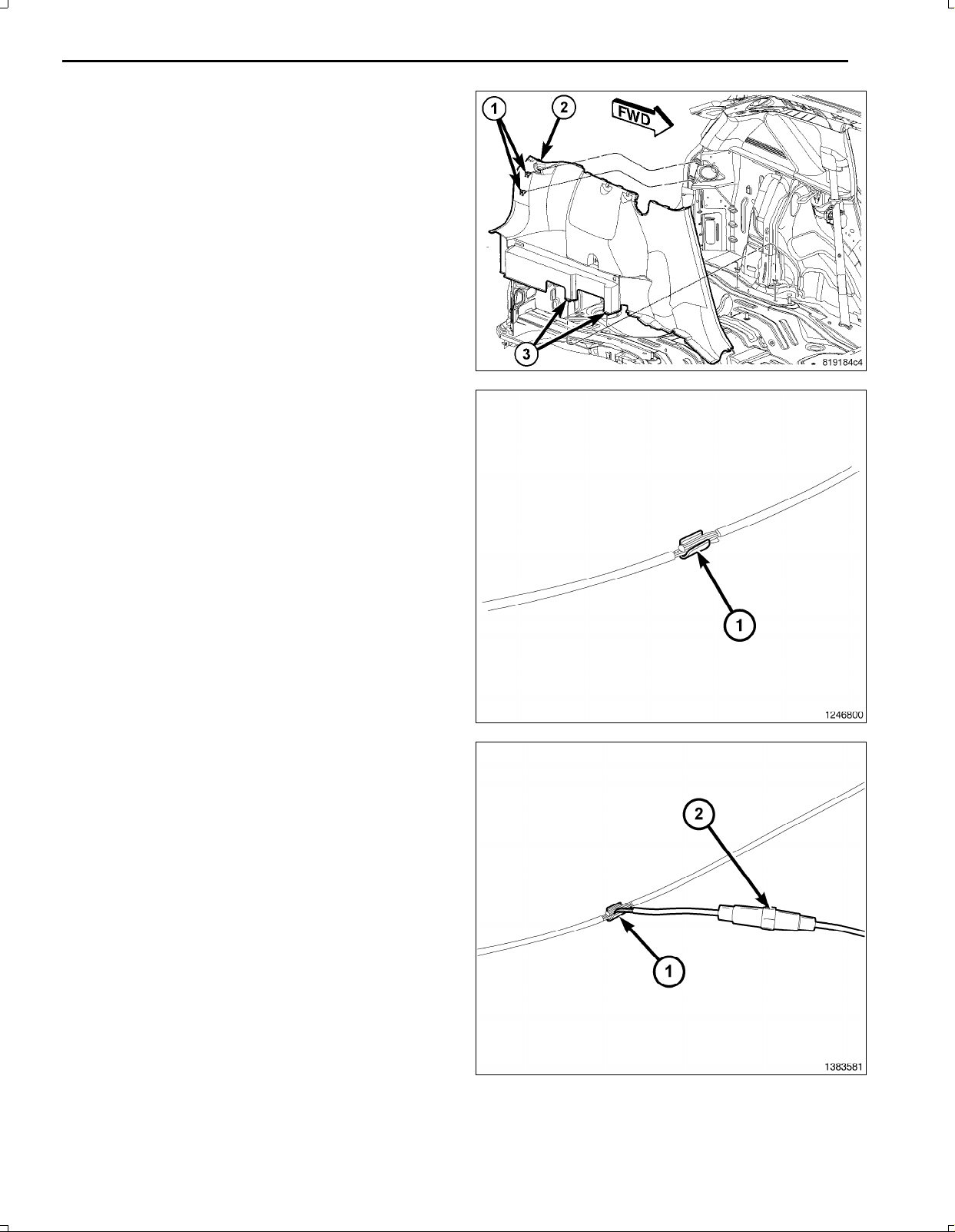
13.Removethethreebolts(1)thatsecuretherearstor
agecompartment(2)tothefloorpanel(3)andremove
thestoragecompartmentfromtherearcabtrimpanel
(4).
Oct16,2009K6860899Rev .1
Page 4
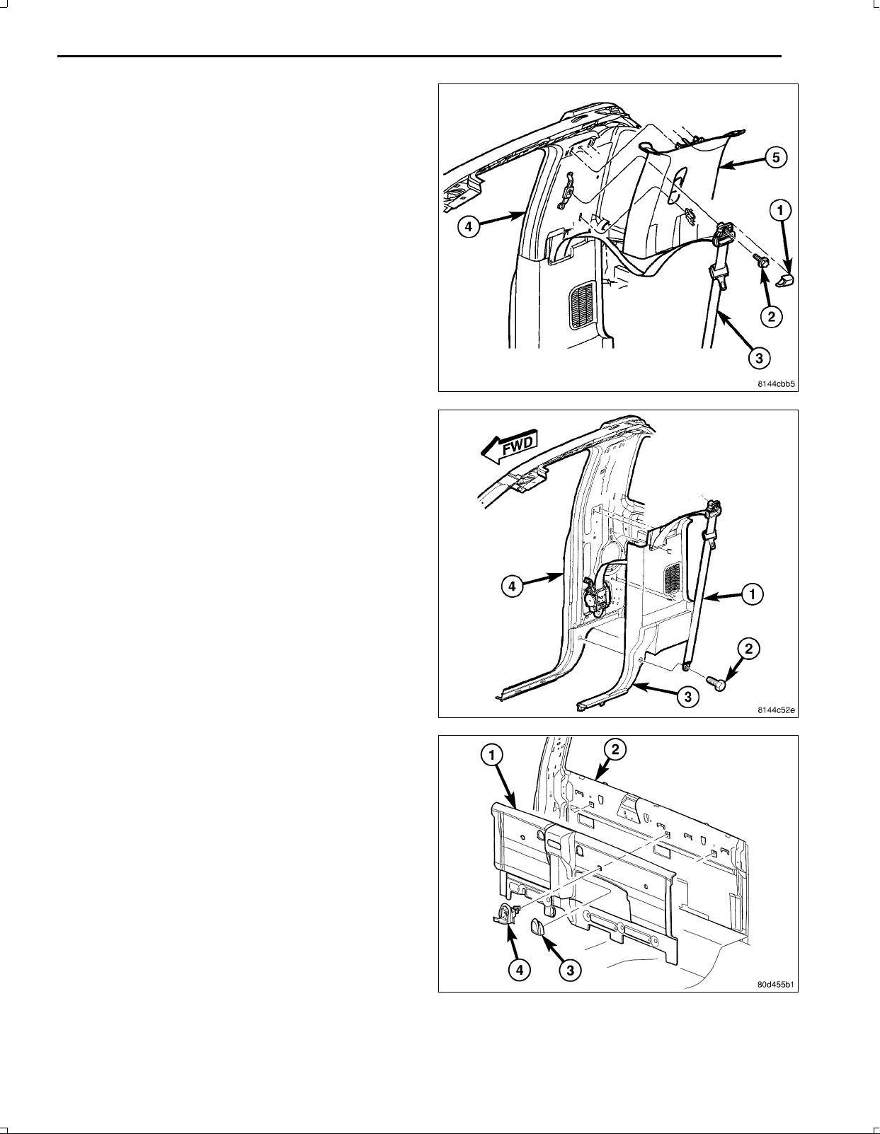
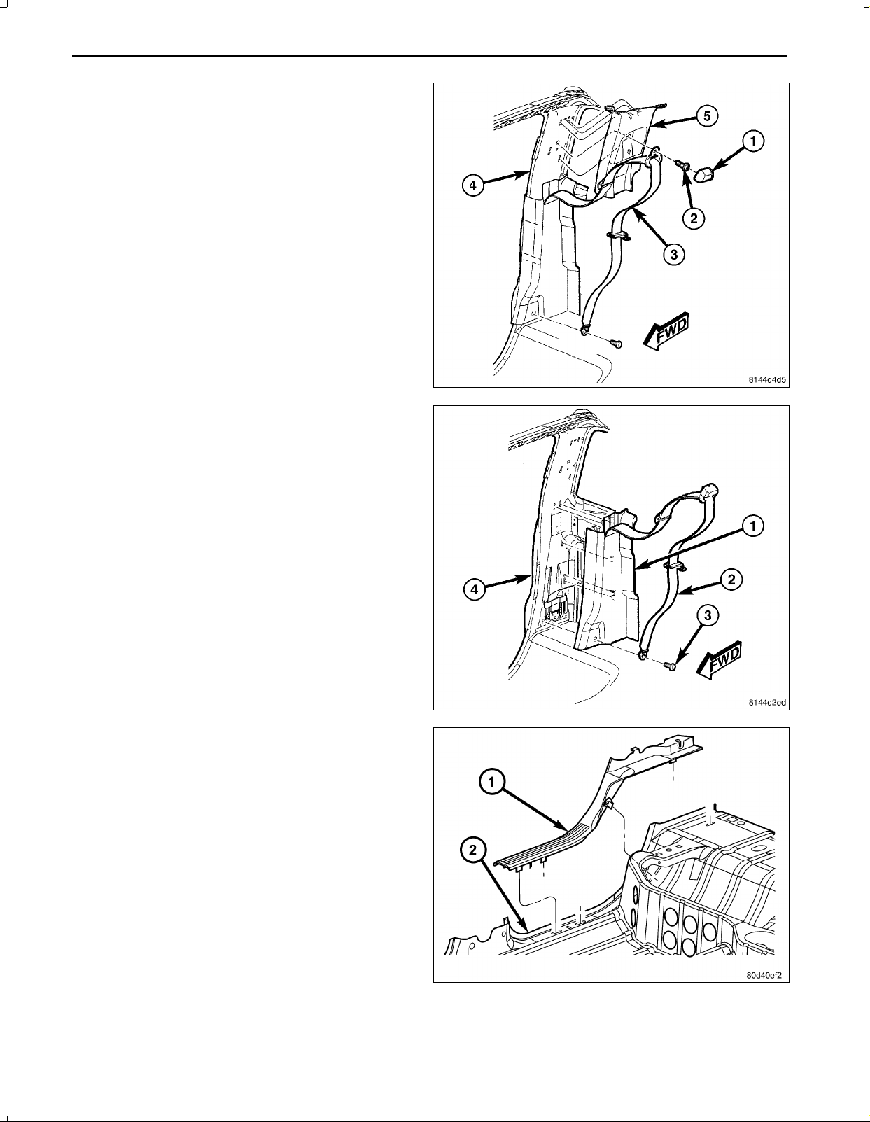
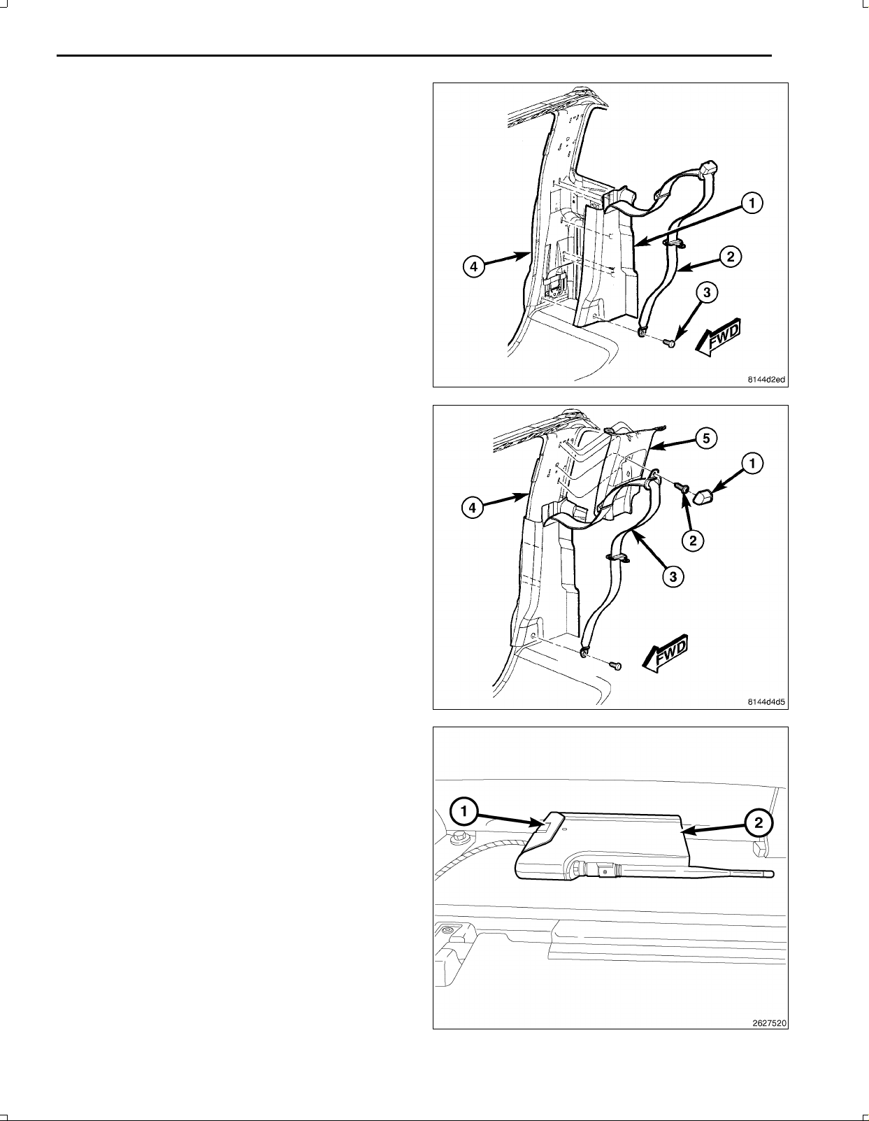
14.Removethecap(1)andthenthebolt(2)thatsecures
theseatbelt(3)tothetopoftheBpillar(4)andposi
tiontheseatbeltoutoftheway.
15.UsingatrimstickC4755orequivalent,disengagethe
retainingtabsthatsecuretheupperBpillartrimpanel
(5)totheBpillarandremovethetrimpanel.
16.Removethebolt(2)thatsecurestheseatbelt(1)to
thebottomoftheBpillar(4)andpositiontheseatbelt
outoftheway.
17.UsingatrimstickC4755orequivalent,disengagethe
retainingtabsthatsecurethelowerBpillartrimpanel
(3)totheBpillar.
18.RemovetheseatbeltfromthelowerBpillartrimpanel
throughtheslotprovidedandremovethetrimpanel.
3
19.Removetheutilityhooks(3)fromtherearcabtrim
panel(1)andremovethetrimpanel.
Oct16,2009K6860899Rev .1
Page 5
4
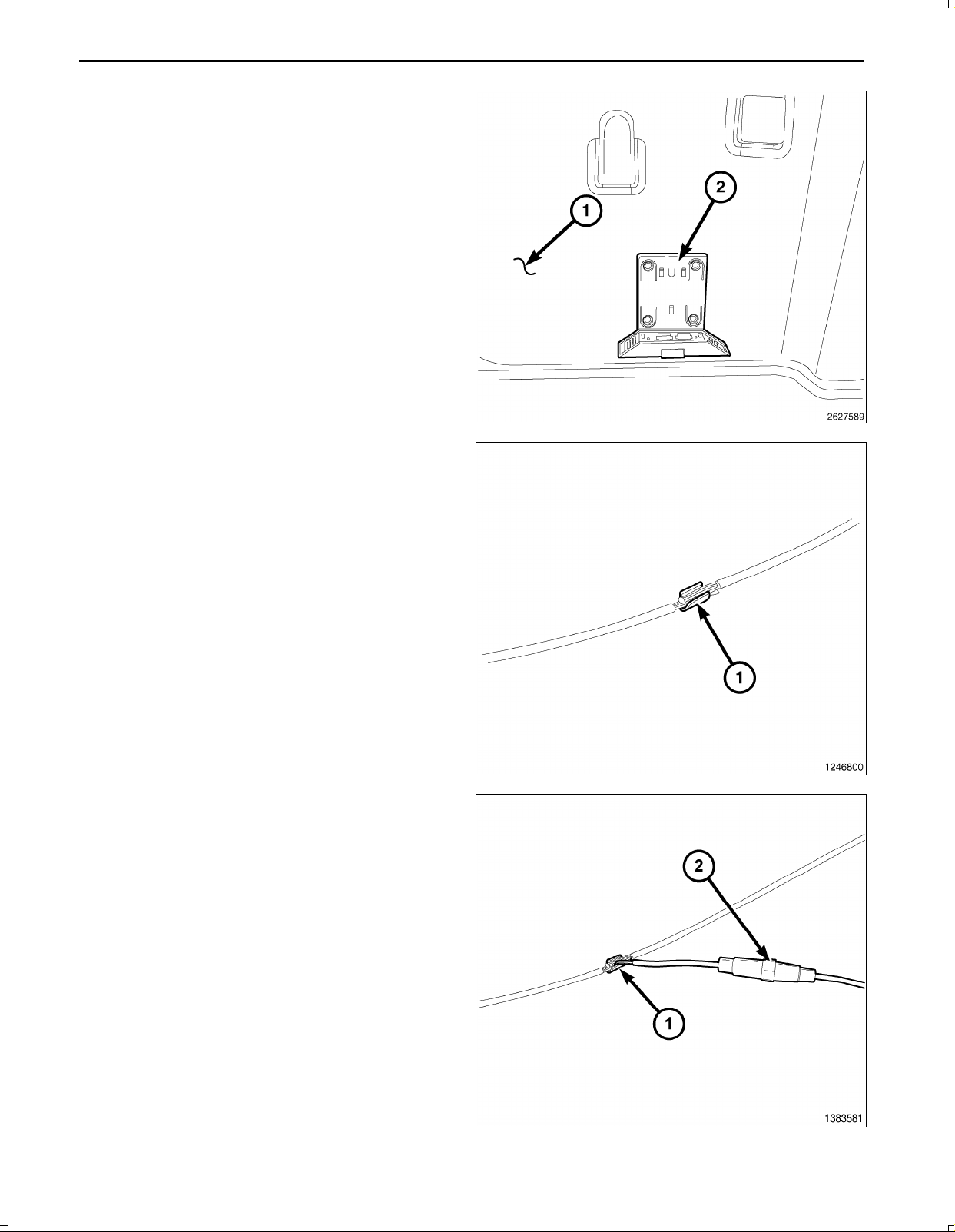
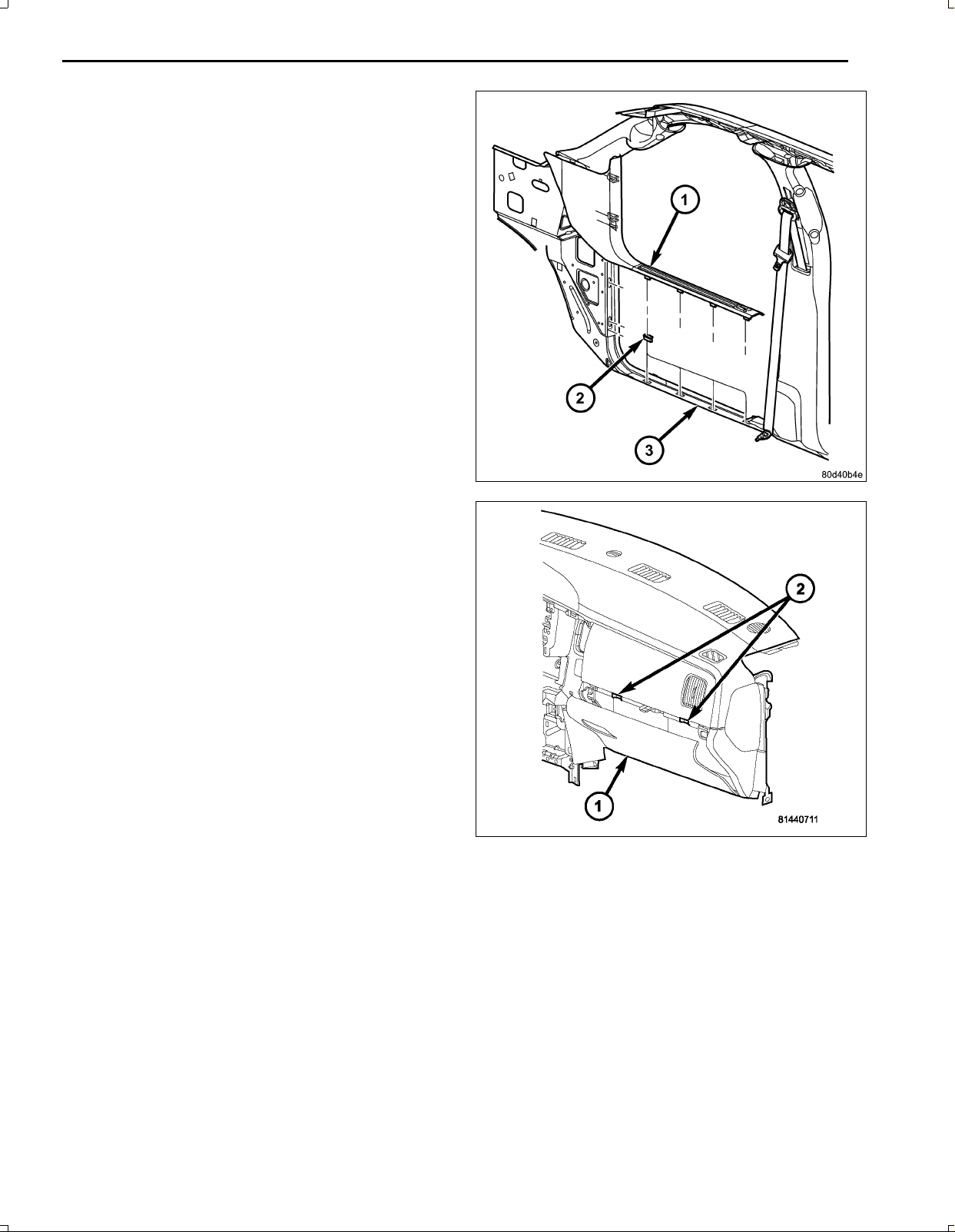
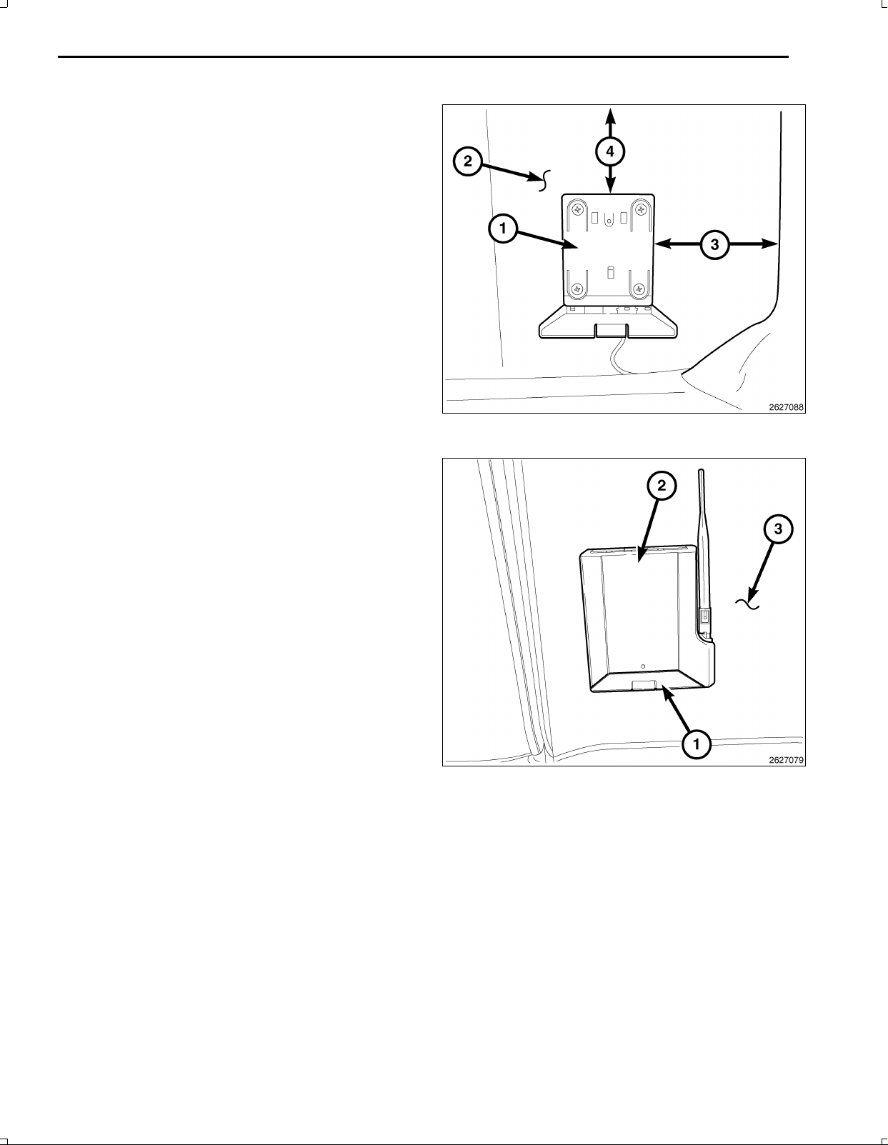
20.InstalltheWiFiroutercradle(2)totherearcabtrim
panel(1)withtheprovidedmaterials.
21.Makeasmallcutintherearcabtrimpanelandroute
theWiFirouterconnectorthrough
22.Placetherearcabtrimpanelintopositioninthevehi
cle.
23.ConnectthewireharnesstotheWiFirouterconnec
tor.
24.Routethewireharnessdownthebackoftherear
paneltothedoorsill.
25.Firmlyseattherearpanelandinstalltheutilityhooks
totherearpanel.
26.Continuetoroutethewireharnessalongthepassen
gerside,underthegloveboxopeningandbehindthe
centerstackandcuttotheproperlength.
27.Locatethecigarettelighteroutletwiringharness.
28.Cuteachwireandremove13mm(0.5in.)ofinsula
tionfromeachwirethatneedstobesoldered/spliced.
29.Placeapieceofsuppliedadhesivelinedheatshrink
tubingononesideofeachcutwire.Insurethetubing
willbelongenoughtocoverandsealtheentiresol
deredarea.
CAUTION:Donotuseacidcoresolder.
30.SolderthesuppliedfusedpigtailtoWiFipowerhar
nesspowerwire(RD/LG).
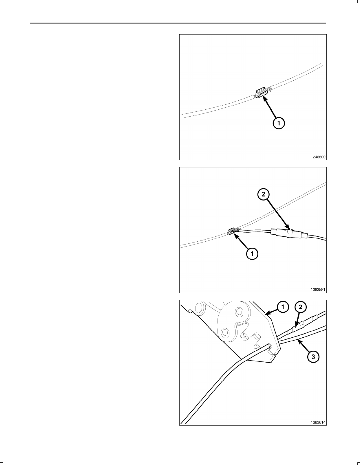
31.Placethestrandsofthepowersidewiresoverlapping
eachotherinsideofthespliceclip(1).
Oct16,2009K6860899Rev .1
Page 6
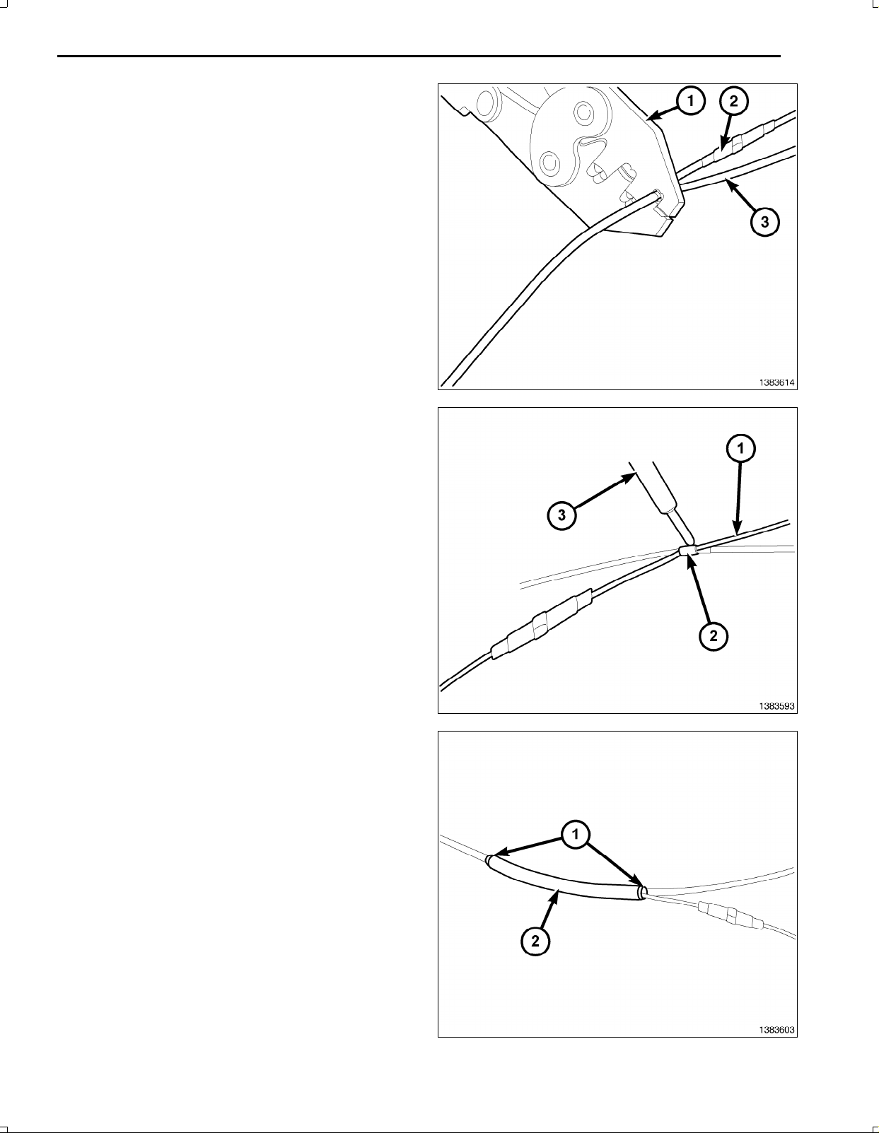
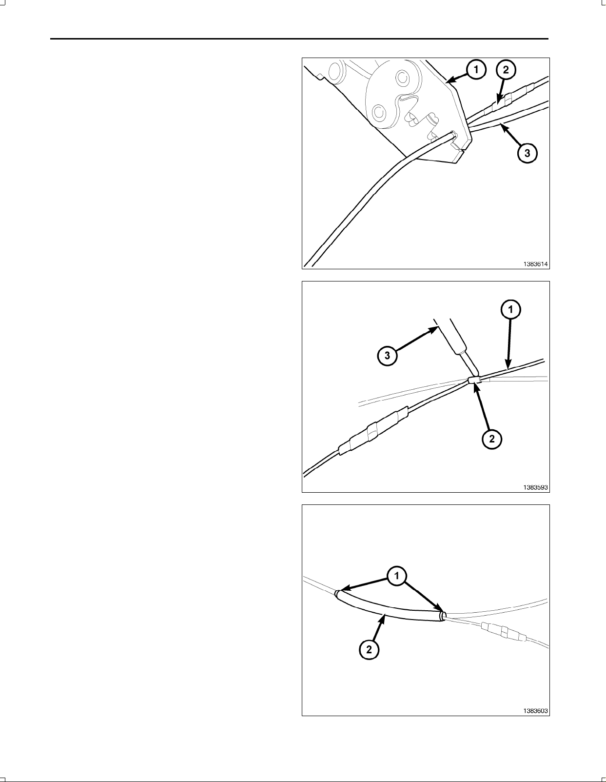
32.Usingcrimpingtool(1),Mopar®p/n05019912AAor
equivalent,crimpthespliceclipandwirestogether.
33.Repeattheprevioustwostepsforthegroundside
wires.
CAUTION:Donotuseacidcoresolder.
34.Solder(3)theconnection(2)togetherusingrosincore
solder(1).
5
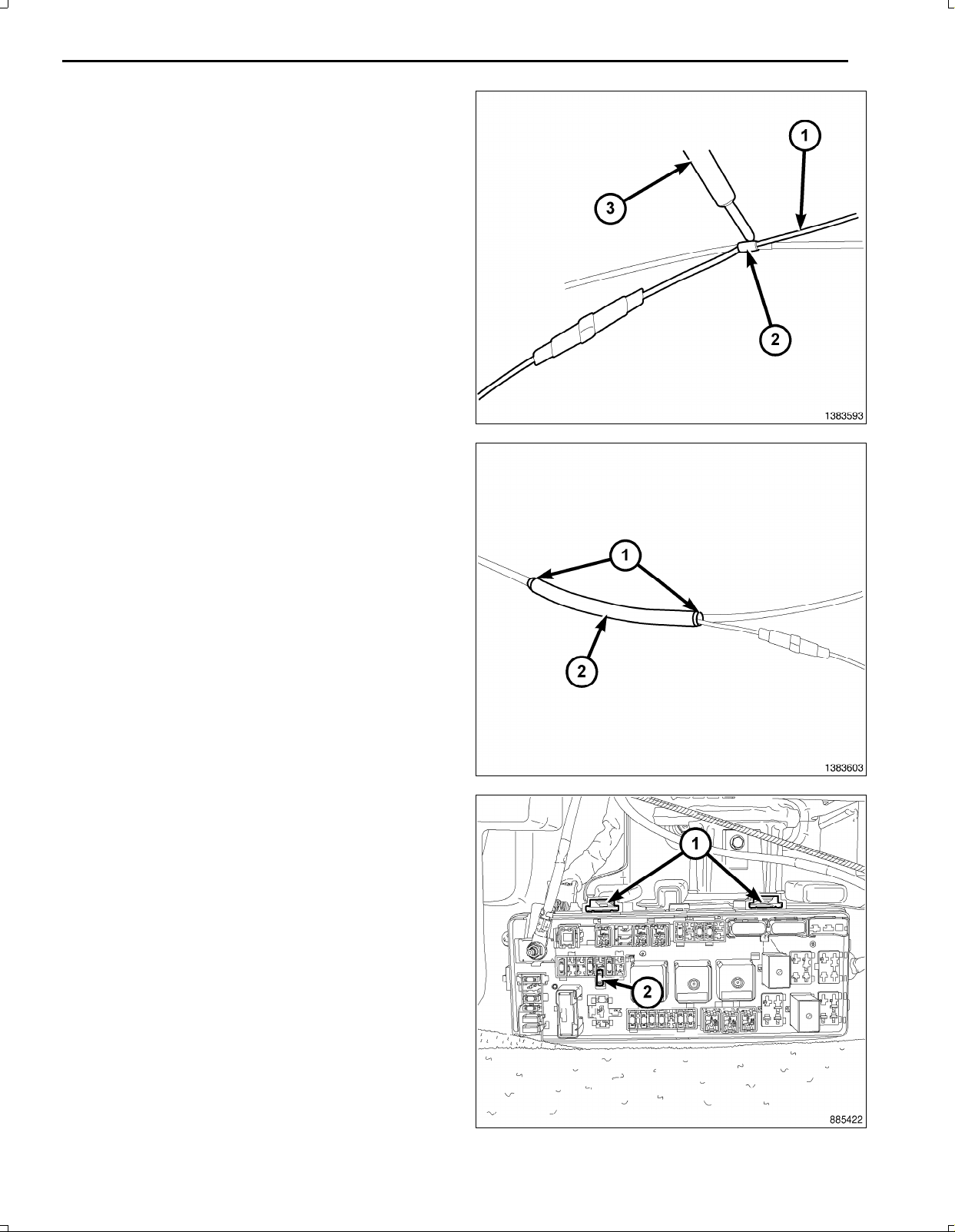
35.Centertheheatshrinktubing(2)overthesolderjoint
andheatusingaheatgun.Heatthejointuntilthetub
ingistightlysealedandsealant(1)comesoutofboth
endsofthetubing.
Oct16,2009K6860899Rev .1
Page 7
6
36.PlacethelowerBpillartrimpanel(3)intopositionand
engagetheretainingtabsthatsecurethetrimpanelto
theBpillar(4).
37.Routetheseatbeltthroughtheslotprovidedinthe
Bpillartrimpanel.
38.Installthebolt(2)thatsecurestheseatbelt(1)tothe
bottomoftheBpillar(4).
39.PlacetheupperBpillartrimpanel(5)intopositionand
engagetheretainingtabsthatsecurethetrimpanelto
theBpillar(4).
40.Installthebolt(2)thatsecurestheseatbelt(3)tothe
topoftheBpillar(4)andInstallthecap(1).
41.Installthestoragecompartment(2)totherearcaband
installthethreefasteners(1)thatsecuretherearstor
agecompartmenttothefloorpanel(3).
Oct16,2009K6860899Rev .1
Page 8
42.Placethecowltrimpanel(1)intopositionandengage
theretainingtabstothedoorsill(3).
7
43.Engagetheglovebox(1)hingestotheinstrument
panel.
44.Pressthetwogloveboxstops(2)andraisetheglove
boxupward.
45.Closetheglovebox.
Oct16,2009K6860899Rev .1
Page 9
8
46.Connectthepoweroutletconnectorsandinstallthe
lowerIPsurroundtothevehicle.
47.Placethecupholderintopositionandinstallthetwo
screwsbehindthecloseout.
48.Foldthecupholderupandinstallthetwolowerscrews
securingthecupholdertotheIP .
49.Installthelowerbezelpanel(1)ensuringtheretaining
tabsengage.
50.InstalltheWiFiRouter(2)intothemountedWiFi
Routercradle(1).
51.Connectthebatterynegativecable.
Oct16,2009K6860899Rev .1
Page 10
WIFIROUTER
PRINT THIS VEHICLE
INDEX
DODGERAM,QUAD/CREWCAB
PROCEDURESTEPS:
NOTE:Usingatestlight,verifythecigarettelighteroutletbeingusedisignitionswitched.Powermustnotbe
presentwiththeignitionintheOFFposition.
1.Disconnectandisolatethenegativebatterycable.
2.Opentheglovebox(1).
3.Releasethetwogloveboxstops(2)andlowerthe
gloveboxdownwardpastthestops.
4.Disengagethegloveboxhingesfromtheinstrument
panelandremovetheglovebox.
1
5.UsingatrimstickC4755orequivalent,disengagethe
retainingtabsofthecowltrimpanel(1)fromthere
tainerclips(2)inthedoorsill(3).
6.Pullthecowltrimpanelrearwardandremoveitfrom
thevehicle.
Oct16,2009K6860899Rev .1
Page 11
2
7.Removethecap(1)andthenthebolt(2)thatsecures
theseatbelt(3)tothetopoftheCpillar(4)andposi
tiontheseatbeltoutoftheway.
8.UsingatrimstickC4755orequivalent,disengagethe
retainingtabsthatsecuretheupperCpillartrimpanel
(5)totheCpillarandremovethetrimpanel.
9.Removethebolt(3)thatsecurestheseatbelt(2)to
thebottomoftheCpillar(4)andpositiontheseatbelt
outoftheway.
10.UsingatrimstickC4755orequivalent,disengagethe
retainingtabsthatsecurethelowerCpillartrimpanel
(1)totheCpillar.
11.RemovetheseatbeltfromthelowerCpillartrimpanel
throughtheslotprovidedandremovethetrimpanel.
12.UsingatrimstickC4755orequivalent,disengagethe
retainingtabsofthesilltrimpanel(1)fromtheretainer
clipsinthereardoorsill(2)andremovethetrimpanel.
Oct16,2009K6860899Rev .1
Page 12
13.InstallandsecuretheWiFiroutercradle(1)tothe
floor(3)withtheprovidedmaterial.
14.RoutetheWiFipowerharnessfromtherouteralong
thesillsecuringwherenecessary.
FULLCENTERCONSOLE
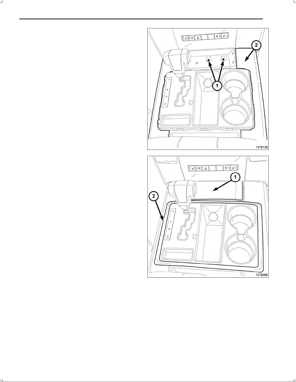
15.Removetherubbermat(1).
16.UsingatrimstickC4755orequivalent,disengagethe
retainingtabsoftheshifterbezelring(2).
3
Oct16,2009K6860899Rev .1
Page 13
4
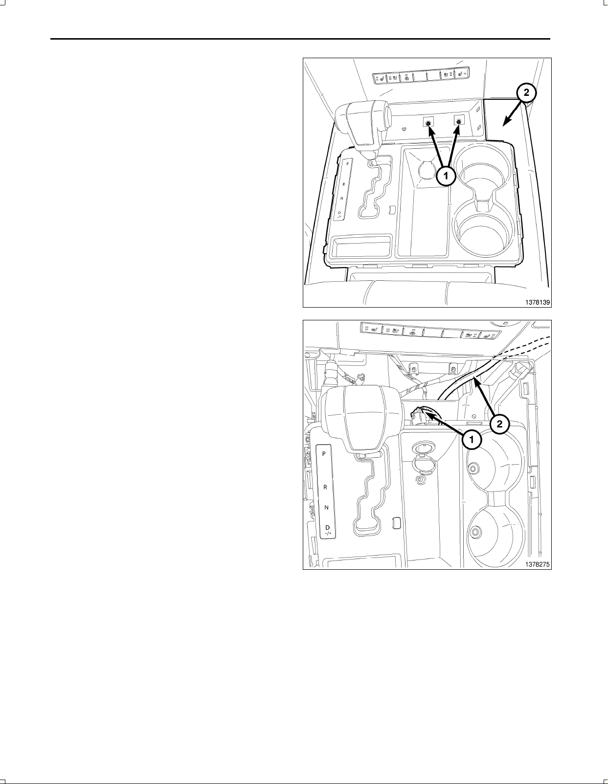
17.Removethetwocenterconsoleretainers(1).
18.UsingatrimstickC4755orequivalent,disengagethe
retainingtabsandremovethecenterconsoletrim(2).
19.Disconnectthepoweroutlet(1).
20.RoutetheWiFipowerharnessbehindtheglovebox
anduptothekeyonpoweroutletandcuttolength.
Oct16,2009K6860899Rev .1
Page 14
WITHOUTFULLCENTERCONSOLE
21.UsingatrimstickC4755orequivalent,disengagethe
retainingtabsandremovethelowerbezelpanel(1).
22.Removethetwolowerscrewssecuringthecupholder
totheIP .
23.Foldthecupholderdownandlowerthecupholder(2)
closeoutpanelbydepressingthetabatthetopofthe
panel.
24.Removethetwoscrewsfrombehindthecloseoutand
removethecupholder.
25.UsingtrimstickC4755orequivalent,disengagethe
poweroutletretainingtabsanddisconnectthepower
outletelectricalconnectors.
26.RemovethelowerIPsurroundfromthevehicle.
27.RoutetheWiFipowerharnessbehindtheglovebox
anduptothekeyonpoweroutletandcuttolength.
ALL
28.Locatethecigarettelighteroutletwiringharness.
29.Cuteachwireandremove13mm(0.5in.)ofinsulation
fromeachwirethatneedstobesoldered/spliced.
30.Placeapieceofsuppliedadhesivelinedheatshrink
tubingononesideofeachcutwire.Insurethetubing
willbelongenoughtocoverandsealtheentiresol
deredarea.
5
CAUTION:Donotuseacidcoresolder.
31.SolderthesuppliedfusedpigtailtoWiFipowerhar
nesspowerwire.
32.Placethestrandsofthepowersidewires(RD/LG)
overlappingeachotherinsideofthespliceclip(1).
Oct16,2009K6860899Rev .1
Page 15
6
33.Usingcrimpingtool(1),Mopar®p/n05019912AAor
equivalent,crimpthespliceclipandwirestogether.
34.Repeattheprevioustwostepsforthegroundside
wires.
35.Solder(3)theconnection(2)togetherusingrosincore
solder(1).
36.Centertheheatshrinktubing(2)overthesolderjoint
andheatusingaheatgun.Heatthejointuntilthetub
ingistightlysealedandsealant(1)comesoutofboth
endsofthetubing.
FULLCENTERCONSOLE
Oct16,2009K6860899Rev .1
Page 16
37.Installthecenterconsoletrim(2).
38.Installthetworetainers(1).
7
39.Installtherubbermat(1).
40.Installtheshifterbezelring(2).
Oct16,2009K6860899Rev .1
Page 17
8
WITHOUTFULLCENTERCONSOLE
41.InstallthelowerIPsurroundtothevehicle.
42.Connectthepoweroutletelectricalconnectorsandin
stallthepoweroutlettrimpanel.
43.Closethecloseoutpanelbydepressingthetabatthe
topofthepanel.
44.Installthetwoscrewsbehindthecloseoutandinstall
thecupholder(2).
45.Installthetwolowerscrewssecuringthecupholderto
theIP .
46.Installthelowerbezelpanel(1).
ALL
47.Positionthecowltrimpanel(1)ontothedoorsill(3).
48.Pushthecowltrimpanelforwardandthenengagethe
retainingtabsthatsecurethesilltrimpaneltotherear
doorsill.
Oct16,2009K6860899Rev .1
Page 18
49.Routetheseatbelt(2)throughtheslotinthelower
Cpillartrimpanel(1)andpositionthetrimpanelto
theCpillar(4).
50.EngagetheretainingtabsthatsecurethelowerCpil
lartrimpaneltotheCpillar.
51.Installthebolt(3)thatsecurestheseatbelttothebot
tomoftheCpillar.Tightentheboltto40N∙m(30ft.
lbs.).
52.PositiontheupperCpillartrimpanel(5)totheCpillar
(4).
53.EngagetheretainingtabsthatsecuretheupperCpil
lartrimpaneltotheCpillar.
54.Installthebolt(2)thatsecurestheseatbelt(3)tothe
topoftheCpillar.Tightentheboltto40N∙m(30ft.
lbs.).
55.Installthecap(1)ontotheseatbelt.
9
56.InstalltheWiFiRouter(2)intothemountedWiFi
Routercradle(1).
57.Connectthenegativebatterycable.
Oct16,2009K6860899Rev .1
Page 19
PROCEDURESTEPS:
NOTE:Charger/300shown,Challengersimilar.
ALLVEHICLES
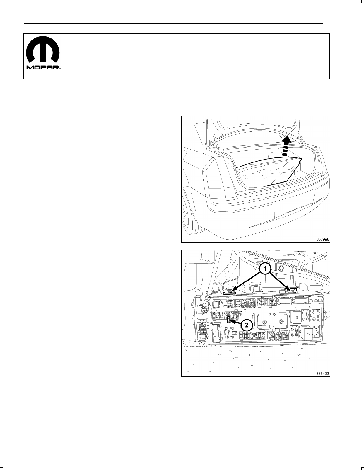
1.Removethesparetirecover.
2.Disconnectandisolatethenegativebatterycable.
1
WIFIROUTER
300/CHARGER/CHALLENGER
3.RemovethePowerDistributionCenter(PDC)cover .
4.RemovethePDCbypressingthereleasingtabs(1)
andpullingthePDCstraightup.
Feb12,2010K6860899Rev .2
Page 20
2
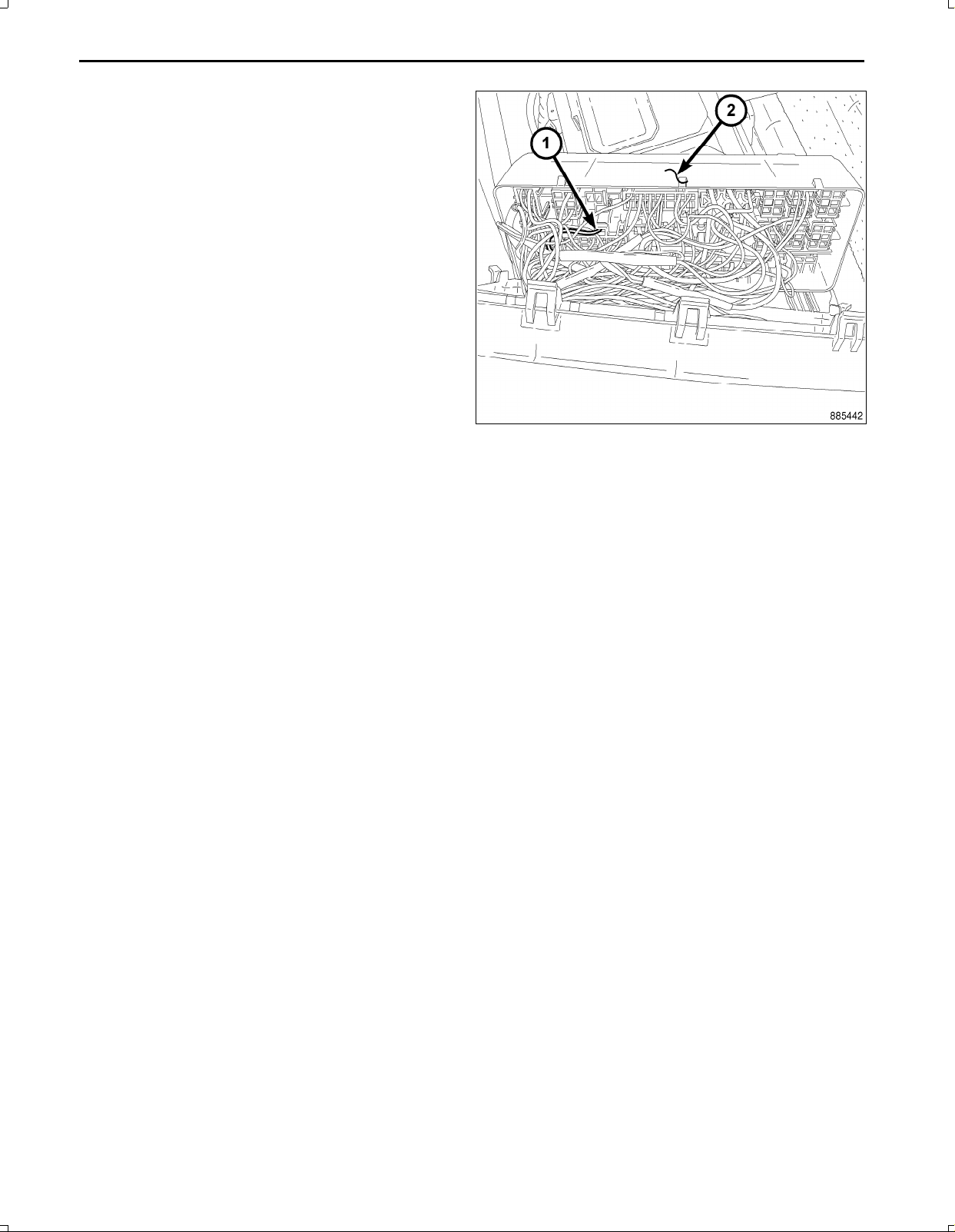
5.RemovethebackcoverofthePDC(2).
6.Measuretheappropriatelengthofwiresothatthewire
harnesswillreachthewifirouterfromthePDC.
Feb12,2010K6860899Rev .2
Page 21
3
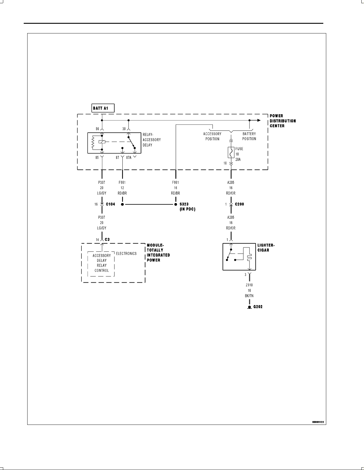
7.LocatetheF981(RD/BR)circuitgoingtofuse18.Refertothewireschematic.
Feb12,2010K6860899Rev .2
Page 22
4
8.SplicetherouterpowerwiretotheF981(RD/BR)cir
cuitusingthedirectionsbelow.
9.Cuteachwireandremove13mm(0.5in.)ofinsula
tionfromeachwirethatneedstobesoldered/spliced.
10.Placeapieceofsuppliedadhesivelinedheatshrink
tubingononesideofeachcutwire.Insurethetubing
willbelongenoughtocoverandsealtheentiresol
deredarea.
CAUTION:Donotuseacidcoresolder.
11.SolderthesuppliedfusedpigtailtoWiFipowerhar
nesspowerwire.
12.Placethestrandsofthepowersidewiresoverlapping
eachotherinsideofthespliceclip(1).
13.Usingcrimpingtool(1),Mopar®p/n05019912AAor
equivalent,crimpthespliceclipandwirestogether.
Feb12,2010K6860899Rev .2
Page 23
14.Solder(3)theconnection(2)togetherusingrosincore
solder(1).
15.Centertheheatshrinktubing(2)overthesolderjoint
andheatusingaheatgun.Heatthejointuntilthetub
ingistightlysealedandsealant(1)comesoutofboth
endsofthetubing.
16.CrimpthesuppliedringterminaltotheWiFiRouter
groundwireatthePDC.
17.SoldertheringterminaltotheWiFiRouterground
wire.
18.AttachtheWiFiRoutergroundwiretothenegative
batteryterminalstud.
5
19.InstallthePDCbackcover,beingcarefulnottopinch
anywiresbetweenthePDCandthePDCcover.
20.InstallthePDC,aligntheclipsonthePDCwiththe
tabsonthemountingbracket.
21.InstallthePDCtopcover.
22.Connectthenegativebatterycable.
Feb12,2010K6860899Rev .2
Page 24
6
23.Installthesparetirecover.
CHALLENGER
1.SecuretheWiFiRoutercradle(1)withthesupplied
fastenersonthebackofthepassengerrearseat(2).
2.Measure108mm(4.25in.)fromthebottomofthe
seatback(6)tothebottomoftheWiFiRoutercradle.
3.Measure76.2mm(3in.)(5)fromtheleftedge(zipper)
(3)totheleftsideoftheWiFiRoutercradle.
Feb12,2010K6860899Rev .2
Page 25
300/CHARGER
1.SecuretheWiFiRouterbracket(1)withthesupplied
fastenersonthebackofthesecondrowseats(2).
2.Measure133mm(5.25in.)(4)fromthebottomofthe
uppersupportbracetothetopoftheWiFiRoutercra
dle.
3.Measure152mm(6in.)(3)fromtherightedgeofthe
WiFiRoutercradle(1)oftheseatbacksupport.
ALLVEHICLES
NOTE:Challengershown,300/Chargersimilar.
7
1.InstalltheWiFiRouter(2)intothemountedWiFi
Routercradle(1).
2.Routeandsecurethetwistedpairwireharnessfrom
thePDCtotheWiFiRouteralongthepassengerside
trunk.
3.Connectthetwistedpairwireharnesstotherouter.
4.Verifysystemoperation.
Feb12,2010K6860899Rev .2
Page 26
WIFIROUTER
PRINT THIS VEHICLE
INDEX
DODGECALIBER
PROCEDURESTEPS:
NOTE:Usingatestlight,ensurethepoweroutletbeingusedisignitionswitched.Powermustnotbepresent
withtheignitionintheOFFposition.
1.Disconnectandisolatethenegativebatterycable.
2.Removethereartonneaucover,ifequipped.
3.Removethecargofloor.
4.RemovetheleftcargonetDring,ifequipped.
5.Removetheliftgateopeningscuffplate(1).
1
6.Removetheseatcushionmountingbolts(2).
7.Liftthefrontofthecushion(3)upandremovethe
cushionfromundertheseatback.
8.Removethebeltbucklebolt(2)andthebuckle(1).
9.Removethefloorbracketorreclinerbolts(4).
Oct16,2009K6860899Rev .1
Page 27
2
10.Foldtheseatsforward.
11.Removethenut(5)andbolts(6)andremovethe40%
seatback(4).
12.UsingspecialtoolC4755,pryoffthelowerBpillar
trim.
13.Removefromvehicle.
14.UsingtrimstickC4755,pryupthescuffplate.
15.Removethescuffplatefromvehicle.
16.Removetheleftsidelowercowltrimpanel.
Oct16,2009K6860899Rev .1
Page 28
17.Pulluponthefrontcornerofthequartertrimandre
leasetheclip.
18.Releasetheremainingclipsandremovetheleftquar
terpaneltrimfromvehicle.
19.Removethelowersteeringcolumncover.
3
20.Pulluponshifterknob(1)andremove.
21.UsingtrimstickC4755orequivalent,pryuponbezel
(2)andremovefromshifterpod(3).
Oct16,2009K6860899Rev .1
Page 29
4
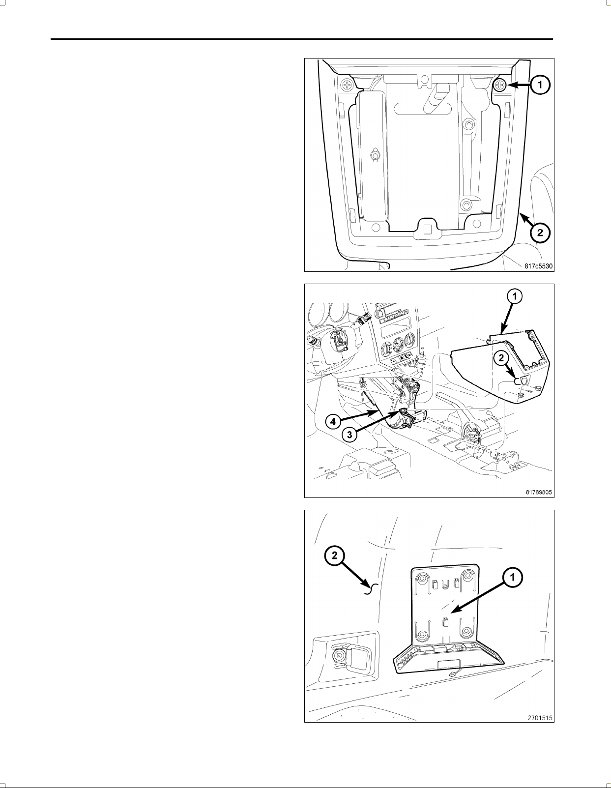
22.Removethetwoscrews(1).
23.Pullonsideofhousing(1)andunsnaphousingtabs.
24.Disconnectconsolehousingwireconnector(2)andin
strumentpanelconnector(3).
25.Removefromvehicle.
26.MounttheWiFirouterbracket(1)totheleftquarter
trimpanel(2)withtheprovidedmaterials.
27.Cutasmallopeninginthequartertrimpanelandroute
theWiFirouterconnectthroughtheopening.
28.Placethequartertrimpanelintoposition,butdonot
engagetheclipretainersatthistime.
29.ConnecttheharnesstotheWiFirouterconnectand
routethecableforwardthroughthevehiclewhiletap
ingtothebodyelectricalharness.
Oct16,2009K6860899Rev .1
Page 30
30.Installthequartertrimpaneltothevehicle,ensuring
theclipretainersengage.
31.Routetheantennacablealongtheleftsideofthevehi
cle,acrossthelowerinstrumentpanelbraceandover
totheshifterhousingatthecigarettelighterconnector,
securingalongthewayandcuttotheproperlength.
32.Locatethecigarettelighteroutletwiringharness.
33.Cuteachwireandremove13mm(0.5in.)ofinsula
tionfromeachwirethatneedstobesoldered/spliced.
34.Placeapieceofsuppliedadhesivelinedheatshrink
tubingononesideofeachcutwire.Insurethetubing
willbelongenoughtocoverandsealtheentiresol
deredarea.
5
35.Placethestrandsofthepowersidewiresoverlapping
eachotherinsideofthespliceclip(1).
Oct16,2009K6860899Rev .1
Page 31

6
36.Usingcrimpingtool(1),Mopar®p/n05019912AAor
equivalent,crimpthespliceclipandwirestogether.
37.Repeattheprevioustwostepsforthegroundside
wires.
38.Solder(3)theconnection(2)togetherusingrosincore
solder(1).
39.Centertheheatshrinktubing(2)overthesolderjoint
andheatusingaheatgun.Heatthejointuntilthetub
ingistightlysealedandsealant(1)comesoutofboth
endsofthetubing.
Oct16,2009K6860899Rev .1
Page 32

40.Connectcenterconsolehousingwireconnector(2)
withinstrumentpanelconnector(3).
41.Placeconsolehousing(1)overshifterleverensuring
consoletabsseatproperly .
42.Installthetwoscrews(1).
7
43.Insertbezel(2)locatortoshifterpod(3).
44.Applyhandpressureuntilclipsareseated.
45.Snapshifterknob(1)ontoshiftershaft.
46.Pulluponknob(1)toverifyseatedcorrectly.
Oct16,2009K6860899Rev .1
Page 33

8
47.Installthelowersteeringcolumncover.
48.Placescuffplate(1)ontodoorsill(2).
49.Alignscuffplatetabswithdoorscuffholes.
50.Handpressscuffplateensuringtabsareproperly
seated.
51.Installtheleftsidelowercowltrimpanel.
52.InsertlowertabsonBpillarlowertrim(1)ontosill
panel.
53.Handtaponcliplocationsensuringclipsareproperly
seated.
Oct16,2009K6860899Rev .1
Page 34

54.Installthe40%seatsection(4)overthestudandseat
bracketandinstalltheseatbracketbolts(6).
55.Tightentheseatbracketbolts(6)to46N∙m(34ft.
lbs.).
56.Installthenut(5).
57.Tightenthenuts(5and3)to80N∙m(60ft.lbs.).
58.Positiontheseatbacks(3)upandlatch.
59.Installthebeltbuckles(1)andinstallthebolt(2).
60.Tightenthebuckleboltto66N∙m(49ft.lbs.)
61.Installthebolts(4)andtightento80N∙m(59ft.lbs.)
9
62.Placetheseatcushionintothevehicleandtuckthe
rearofthecushion(1)upundertheseatbeltbuckles
andrearseatback.
63.Lowerthefrontofthecushion(3)downandinstallthe
bolts(2).
64.Tightentheboltsto80N∙m(60ft.lbs.).
Oct16,2009K6860899Rev .1
Page 35

10
65.Locatetrimclipsandalignmetalclipstoliftgateinner.
66.T aponpanelateachtrimcliplocation(2)untilproperly
seated.
67.InstalltheleftcargonetDring,ifequipped.
68.Installthecargofloor.
69.Installthereartonneaucover,ifequipped.
70.InstalltheWiFirouter(1)intotherouterbracket(2).
71.Connectthebatterynegativecable.
72.Verifysystemoperation.
Oct16,2009K6860899Rev .1
Page 36

WIFIROUTER
PRINT THIS VEHICLE
INDEX
JEEPCOMPASS
PROCEDURESTEPS:
NOTE:Usingatestlight,ensurethecigarettelighteroutletbeingusedisignitionswitched.Powermustnotbe
presentwiththeignitionintheOFFposition.
1.Disconnectandisolatethebatterynegativecable.
2.Pulluponshifterknob(3)andremove.
3.UsingtrimstickC4755orequivalent,separatethe
bezel(4)fromthetrimring(5),ifequipped.
4.Removethescrews(2)andusingtrimstickC4755or
equivalent,separatethetrimring(5)fromtheshifter
console(6).
1
5.Lookinsideandnotepositionoftheretainingbosses.
6.Usingspecialtool9857PowerOutletRemover(4),in
sertthetoolforcingbosses(1)outofbase.
7.Pulloutthebase(3)throughmountingringbygently
rockingpliers.
8.Disconnecttheelectricalconnector.
Oct16,2009K6860899Rev .1
Page 37

2
9.InstalltheWiFirouterbracket(1)underthepassen
gerseatwiththeprovidedmaterials.
10.ConnectthewireharnesstotheWiFirouterbracket
harness.
11.RoutetheWiFipowerharnessunderthecentercon
soletotheshifterhousingandcuttheharnesstothe
properlength.Ensuretheharnessistuckedunderthe
centerconsoletominimizevisiblewire.
12.Locatethecigarettelighteroutletwiringharness.
13.Cuteachwireandremove13mm(0.5in.)ofinsula
tionfromeachwirethatneedstobesoldered/spliced.
14.Placeapieceofsuppliedadhesivelinedheatshrink
tubingononesideofeachcutwire.Insurethetubing
willbelongenoughtocoverandsealtheentiresol
deredarea.
CAUTION:Donotuseacidcoresolder.
15.SolderthesuppliedfusedpigtailtoWiFipowerhar
nesspowerwire.
16.Placethestrandsofthepowersidewiresoverlapping
eachotherinsideofthespliceclip(1).
Oct16,2009K6860899Rev .1
Page 38

17.Usingcrimpingtool(1),Mopar®p/n05019912AAor
equivalent,crimpthespliceclipandwirestogether.
18.Repeattheprevioustwostepsforthegroundside
wires.
19.Solder(3)theconnection(2)togetherusingrosincore
solder(1).
3
20.Centertheheatshrinktubing(2)overthesolderjoint
andheatusingaheatgun.Heatthejointuntilthetub
ingistightlysealedandsealant(1)comesoutofboth
endsofthetubing.
Oct16,2009K6860899Rev .1
Page 39

4
21.Connecttheelectricalconnectortothecigarette
lighteroutletandfirmlyseattheoutlettotheshifter
housing.
22.Installthetrimring(5)ontotheshifterconsole(6)and
seatfully.
23.Installthescrews(2).
24.Installthebezel(4)ontothetrimring(5)andseatfully.
25.Installtheshiftknob(3)ontotheshifter(1)andseat
fully.
26.InstalltheWiFirouter(1)totheWiFibracket(2).
27.Connectthebatterynegativecable.
28.Verifysystemoperation.
Oct16,2009K6860899Rev .1
Page 40

WIFIROUTER
PRINT THIS VEHICLE
INDEX
DAKOTA
PROCEDURESTEPS:
1.Disconnectandisolatethenegativebatterycable.
WARNING:Toavoidpersonalinjuryordeath,whenhandlingaseatbelttensionerretractor ,exercisepropercare
tokeepfingersoutfromundertheretractorcoverandawayfromtheseatbeltwebbingwhereitexitsfromthe
retractorcover.Failuretofollowtheseinstructionsmayresultinpossibleseriousorfatalinjury.
WARNING:T oavoidseriousorfatalinjuryonvehiclesequippedwithairbags,disabletheSupplementalRestraint
System(SRS)beforeattemptinganysteeringwheel,steeringcolumn,airbag,seatbelttensioner,impactsensor,
orinstrumentpanelcomponentdiagnosisorservice.Disconnectandisolatethebatterynegative(ground)ca
ble,thenwaittwominutesforthesystemcapacitortodischargebeforeperformingfurtherdiagnosisorservice.
ThisistheonlysurewaytodisabletheSRS.Failuretotaketheproperprecautionscouldresultinaccidental
airbagdeployment.
CLUBCAB
2.Removethetwoplasticpushpinretainers(2)thatse
curetheouterfrontseatbeltretractorcover(1)tothe
outerfrontseatbeltretractor(3).
3.Raisetheretractorcoverupwardtodisengagethetwo
locatorpinsontheinsidetopoftheinboardretractor
coverfromthelocatorholesinthetopoftheretractor.
1
4.Spreadthebottomoftheinboard(1)andoutboard(3)
retractorcoverhalvesapartanddisengagethesnaps
locatedatthetopofthecoverhalvesandremovethe
coverhalves.
Oct16,2009K6860899Rev .1
Page 41

2
5.Toaccessthereardoorsillscuffplateforremoval,use
atrimstickC4755orequivalenttodisengageenough
oftheretainingtabs(2)thatsecurethedoorsillscuff
plateendofthecowltrimpaneltotheretainingclips
inthefrontdoorsill.
6.UsingatrimstickC4755orequivalent,disengagethe
retainingtabs(2)thatsecurethereardoorsillscuff
plate(1)totheretainingclipsinthereardoorsilland
removethescuffplate.
7.UsingatrimstickC4755orequivalent,disengagethe
retainingtabs(2)thatsecurethereardoorsillscuff
plate(1)totheretainingclipsinthereardoorsilland
removethescuffplate.
8.SecuretheWiFiroutertothefloorbetweentherear
seatswiththeprovidedmaterials.
9.ConnecttheWiFiharnesstotheWiFirouter.
10.RoutetheWiFiharnessbehindthereardriversside
seatriser.
11.RouteandsecuretheWiFiharnessdownthedrivers
side.
Oct16,2009K6860899Rev .1
Page 42

QUADCAB
12.UsingatrimstickC4755orequivalent,disengagethe
retainingtabsthatsecurethedoorsillscuffplate(1)
endofthecowltrimpaneltotheretainingclips(2)in
thefrontdoorsill(3).
13.Pullthedoorsillscuffplateendofthecowltrimpanel
upwardtodisengagetheretainingtabsthatsecurethe
trimpaneltothecowlandremovethetrimpanel.
14.Raisethedriver'ssiderearseat(2).
3
15.SecuretheWiFirouterbracket(1)tothefloorbelow
therearseatback(2)withtheprovidedmaterials.
16.ConnecttheWiFiharness(3)totheWiFirouter(1).
17.RoutetheWiFiharness(3)behindthereardrivers
sideseatriser .
Oct16,2009K6860899Rev .1
Page 43

4
ALL
18.RouteandsecuretheWiFiharnessalongscuffplates
totheinstrumentpanel.
19.UsingatrimstickC4755orequivalent,separatethe
endcapretainingclipsandremovetheendcap.
20.Pulltheparkbrakereleasehandle(1)out,releasethe
clip(2)anddisconnectthereleaserod(3).
21.Removethetwoscrews(3).
22.UsingatrimstickC4755orequivalent,separate
theupperretainingclips(1)andremovetheopening
cover(2).
Oct16,2009K6860899Rev .1
Page 44

23.Removethetwoscrews(3).
24.UsingatrimstickC4755orequivalent,separatethe
fourretainingclips(1)andremovethebezel(2).
25.Disconnecttheelectricalconnectorsandremovethe
bezel.
26.RouteandsecuretheWiFiharnessacrossthe
steeringcolumnopeningtothecenterstackandcut
tolength.
5
27.Locatethecigarettelighteroutletwiringharness.
28.Cuteachwireandremove13mm(0.5in.)ofinsula
tionfromeachwirethatneedstobesoldered/spliced.
29.Placeapieceofsuppliedadhesivelinedheatshrink
tubingononesideofeachcutwire.Insurethetubing
willbelongenoughtocoverandsealtheentiresol
deredarea.
CAUTION:Donotuseacidcoresolder.
30.SolderthesuppliedfusedpigtailtoWiFipowerhar
nesspowerwire.
Oct16,2009K6860899Rev .1
Page 45

6
31.Placethestrandsofthepowersidewiresoverlapping
eachotherinsideofthespliceclip(1).
32.Usingcrimpingtool(1),Mopar®p/n05019912AAor
equivalent,crimpthespliceclipandwirestogether.
33.Repeattheprevioustwostepsforthegroundside
wires.
34.Solder(3)theconnection(2)togetherusingrosincore
solder(1).
Oct16,2009K6860899Rev .1
Page 46

Centertheheatshrinktubing(2)overthesolderjointand
heatusingaheatgun.Heatthejointuntilthetubingis
tightlysealedandsealant(1)comesoutofbothendsof
thetubing.
35.Connecttheelectricalconnectors.
7
36.Installthecenterbezel(2)andseatthefourretaining
clips(1)fully .
37.Installthescrews(3).
Oct16,2009K6860899Rev .1
Page 47

8
38.Positionthecolumncoveragainstthereinforcement
androutethebrakereleaserodthroughtheholein
cover.
39.Seattheupperretainingclips(1)fullyandinstallthe
bottomandsidescrews(3).
40.Connectthereleaserod(3)tothereleasehandle(1)
andsecuretheattachmentclip(2)fully.
41.Positiontheendcapandseattheretainingclipsfully .
Oct16,2009K6860899Rev .1
Page 48

CLUBCAB
42.Positionthecowltrimpanel(1)inthevehiclewiththe
doorsillscuffplateend(2)ofthetrimpanelangled
upward.Seattheupperouterendofthetrimpanel
underneaththedashpanelandengagetheretaining
tabsthatsecurethetrimpaneltothecowl.
43.Aligntheretainingtabsonthedoorsillscuffplateend
ofthetrimpanelwiththeretainingclipsinthefront
doorsillandengagetheretainingtabsthatsecurethe
trimpaneltothedoorsill.
44.Aligntheretainingtabs(2)onthereardoorsillscuff
plate(1)withtheretainingclipsinthereardoorsilland
engagetheretainingtabsthatsecurethescuffplate
tothedoorsill.
9
45.Positiontheinboard(1)andoutboard(3)outerseat
beltretractorcoverhalvesaroundtheseatbelt(2)with
thetopofeachhalfangledtowardtheotheranden
gagethesnapsthatsecurethetwohalvestogether.
Then,closethecoveraroundtheseatbelt.
Oct16,2009K6860899Rev .1
Page 49

10
46.Usinghandpressure,pushtheretractorcover(1)
downwardovertheretractor(3)farenoughtoengage
thetwolocatorpinsinthetopoftheinboardcover
halfwiththelocatorholesinthetopoftheretractor.
47.Installthetwoplasticpushpinretainers(2)thatse
curetheretractorcovertotheretractor.
QUADCAB
48.Positionthecowltrimpanelinthevehiclewiththedoor
sillscuffplateend(1)ofthetrimpanelangledupward.
Seattheupperouterendofthetrimpanelunderneath
thedashpanelandengagetheretainingtabsthatse
curethetrimpaneltothecowl.
49.Aligntheretainingtabsonthedoorsillscuffplateend
ofthetrimpanelwiththeretainingclips(2)inthefront
doorsill(3)andengagetheretainingtabsthatsecure
thetrimpaneltothedoorsill.
Oct16,2009K6860899Rev .1
Page 50

50.Aligntheretainingtabs(2)onthereardoorsillscuff
plate(1)withtheretainingclipsinthereardoorsilland
engagetheretainingtabsthatsecurethescuffplate
tothedoorsill.
51.Lowerthedriver'ssiderearseat.
ALL
52.InstalltheWiFirouter(1)intotherouterbracket(2).
53.Connectthenegativebatterycable.
54.Verifysystemoperation.
11
Oct16,2009K6860899Rev .1
Page 51

WIFIROUTER
PRINT THIS VEHICLE
INDEX
GRANDCHEROKEE
PROCEDURESTEPS:
NOTE:Usingatestlight,verifythecigarettelighteroutletbeingusedisignitionswitched.Powermustnotbe
presentwiththeignitionintheOFFposition.
1.Disconnectthenegativebatterycable.
2.UsingtrimstickC4755orequivalent,disengagethe
retainingtabsthatsecuretheupperCpillartrimpanel
totheretainingclipsintheCpillarandpositionthe
panelandtheseatbeltoutoftheway.
3.Removethefrontandrearpassengerdoorsillscuff
plate.UsingtrimstickC4755orequivalent,disen
gagetheretainingtabsthatsecurethedoorsillscuff
platetotheretainingclipsinthedoorsillandremove
thescuffplate.
1
4.Removetheliftgatescuffplate.Usingtrimstick
C4755orequivalent,disengagetheretainingtabs
thatsecuretheliftgatescuffplatetotheliftgatedoor
sillandremovethescuffplate.
Oct16,2009K6860899Rev .1
Page 52

2
5.Removetheupperliftgatetrimpanel.Usingtrim
stickC4755orequivalent,disengagetheretaining
tabsthatsecuretheupperliftgatetrimpaneltothe
retainingclipsintheliftgateopeningandremovethe
trimpanel.
6.RemovetheDpillartrimpanel.Usingtrimstick
C4755orequivalent,disengagetheretainingtabs
thatsecuretheDpillartrimpaneltotheretaining
clipsintheDpillarandremovethetrimpanel.
7.Removethetwonutsthatsecuretheloadfloortothe
floorpanelandremovetheloadfloor.
8.UsingtrimstickC4755orequivalent,disengagethe
retainingtabsthatsecurethequartertrimpaneltothe
quarterpanel.
9.Pullthequartertrimpanelawayfromthequarter
panel.
10.Ifequipped,disconnectthepoweroutletwireharness
connector.
11.Removethequartertrimpanel.
Oct16,2009K6860899Rev .1
Page 53

12.Removethehushpanelfromunderneaththeinstru
mentpanel.
13.Removethenutthatsecuresthecowltrimpaneltothe
mountingbracket.
14.Removethecowltrimpanel.
15.Removetheshiftertrim(1)andbezel(2).
3
16.Removethecenterstackbezel(2).
Oct16,2009K6860899Rev .1
Page 54

4
NOTE:MakesureenoughwirelengthissuppliedtogointotheloadfloorwheretheWiFirouter(1)willbe
located.
17.RouteandsecuretheWiFipowerharnessfromrear
quarterpanel,alongthepassengersideandunder
neaththedoorsillscuffplate.
18.Routeandsecurethepowerharnessundertheglove
boxandbehindthecenterstack.
NOTE:DonotusethepoweroutletwiringfortheWiFi
Router.
19.Locatethecigarettelighteroutletwiringharness.
20.Splicethesuppliedfusedpigtail(2)intothecigarette
lighterpowerwireandinserieswiththeWiFipower
harness.
21.Remove13mm(0.5in.)ofinsulationfromeachwire
thatneedstobespliced.
22.Placeapieceofadhesivelinedheatshrinktubingon
onesideofthewire.Makesurethetubingwillbelong
enoughtocoverandsealtheentirerepairarea.
23.Placethestrandsofwireoverlappingeachotherin
sideofthespliceclip(1).
Oct16,2009K6860899Rev .1
Page 55

24.Usingcrimpingtool(1),Moparp/n05019912AAor
equivalent,crimpthespliceclipandwirestogether.
CAUTION:Donotuseacidcoresolder.
25.Solder(3)theconnection(2)togetherusingrosincore
typesolder(1)only.
5
26.Centertheheatshrinktubing(2)overthejointand
heatusingaheatgun.Heatthejointuntilthetubingis
tightlysealedandsealant(1)comesoutofbothends
ofthetubing.
Oct16,2009K6860899Rev .1
Page 56

6
27.InstalltheCenterstackbezel(2).
28.Installtheshiftertrim(2)andbezel(1).
29.Alignthefastenerholeinthecowltrimpanelwiththe
studonthemountingbracketandthenseatthetrim
panelontothemountingbracket.
30.Installthenutthatsecuresthecowltrimpaneltothe
mountingbracket.
31.Installthehushpanel.
Oct16,2009K6860899Rev .1
Page 57

32.Positionthequartertrimpanelinthevehicle.
33.Ifequipped,connectthewireharnessconnectortothe
poweroutlet.
34.Positiontheflangeonthequartertrimpanelintothe
sealditchandsecurethebottomclipfirstandthenthe
middleclip.
35.Alignthetwofastenerholesinthequartertrimpanel
withthetwofastenerholesinthequarterpaneland
engagetheretainingtabsthatsecurethequartertrim
paneltothequarterpanel.
36.Installthetwoscrewsthatsecurethequartertrim
paneltothequarterpanel.
37.Positiontheloadfloorinthevehicle.Routethetwisted
pairwireharness(2)throughthebottomofthefloor
andconnecttheharnesstotheWiFiRouterconnec
tor.
38.Installthetwonutsthatsecuretheloadfloortothe
floorpanel.
39.Usingthesuppliedselftappingscrews,securethe
WiFiRouterbracket(1)totheloadfloor.
7
40.InstalltheDpillartrimpanel.Positionthelocatingtabs
onthebottomoftheDpillartrimpanelintotheslots
inthetopofthequartertrimpanel.
41.AligntheretainingtabsontheDpillartrimpanelwith
theretainingclipsintheDpillarandengagethere
tainingtabsthatsecurethetrimpaneltotheDpillar.
Oct16,2009K6860899Rev .1
Page 58

8
42.Installtheupperliftgatetrimpanel.Aligntheretaining
tabsontheupperliftgatetrimpanelwiththeretaining
clipsintheliftgateopeningandengagetheretaining
tabsthatsecurethetrimpaneltotheliftgateopening.
43.Installtheliftgatescuffplate.
44.Positionthelocatingtabsonthebottomoftheupper
Cpillartrimpanelintotheslotsinthetopofthequarter
trimpanel.
45.AligntheretainingtabsontheupperCpillartrimpanel
withtheretainingclipsintheCpillarandengagethe
retainingtabsthatsecurethetrimpaneltotheCpillar.
46.Aligntheretainingtabsonthedoorsillscuffplatewith
theretainingclipsinthedoorsillandengagethere
tainingtabsthatsecurethescuffplatetothedoorsill.
Oct16,2009K6860899Rev .1
Page 59

47.InstalltheWiFirouter(1)intotherouterbracket(2).
48.Connectthenegativebatterycable.
49.Verifysystemoperation.
9
Oct16,2009K6860899Rev .1
Page 60

WIFIROUTER
JOURNEY
PROCEDURESTEPS:
NOTE:Usingatestlight,verifythecigarettelighteroutletbeingusedisignitionswitched.Powermustnotbe
presentwiththeignitionintheOFFposition.
1.Disconnectandisolatethenegativebatterycable.
STORAGEBOX–5PASSENGER
1
1.Removethematcoveringthestoragebox.
2.Removetheloadfloorassembly(3).
3.SecuretheWiFirouter(1)tothefloorwiththemate
rialsprovidedasshownintheimage.
Feb12,2010K6860631Rev .2
Page 61

2
STORAGEBOX–7PASSENGER
1.Openthestoragebinlid.
2.SecuretheWiFirouter(1)tothefloorwiththemate
rialsprovided.
ALL
NOTE:Driversideshown,passengersidesimilar
1.PlugtheWiFipowerharnessintotheWiFirouter.
2.RoutetheWiFipowerharnessoverthetopofthe
storageboxanddownthepassengersidequarter
trimpanel.
3.UsingatrimstickC4755disengagetheclipsholding
thepassengersidedoorsillscuffpanelandtothedoor
sill.
4.Startingattheforwardendofthedoorsillscuffpanel
(1),pullupwardonthesillscuffpanelinordertodis
engagetheclipsattachingthesillscuffpaneltothe
dooropeningflange.
5.Removethepassengersidedoorsillscuffpanel(1)
fromthevehicle.
Feb12,2010K6860631Rev .2
Page 62

6.UsingatrimstickC4755,disengagethepassenger
sidecowltrimpanelclipsfromthecorrespondinglo
cationsinthesheetmetal.
7.Removethepassengersidecowltrimpanel(1)from
thevehicle.
8.Removethepassengersidecloseoutpanelpushpins
fasteningthecloseoutpanelstothebottomofthein
strumentpanel.
9.Removethecloseoutpanelsfromtheinstrument
panel.
10.Positionthesecondrowpassengersideseatflat.
11.RoutetheWiFipowerharnessunderthepassenger
sidequartertrimpanel.
12.RoutetheWiFipowerharnessunderthepassenger
sidebpillartrimpanel.
13.RoutetheWiFipowerharnesstothepassengerside
cowlarea.
3
Feb12,2010K6860631Rev .2
Page 63

4
14.Removethepushpinretainersbypressingthecenter
inwardtoreleasethenpryingtheretaineroutofthe
storagebin.
15.UsingPowerOutletRemover9857(4).Insertthetool
withtipsagainstbosses(1).
16.Pulloutthebase(3)throughmountingringbygently
rockingpoweroutletremover.
17.Disconnectthebasewires(2).
Feb12,2010K6860631Rev .2
Page 64

18.RoutetheWiFipowerharness(3)underthecarpet
tothebackofthestoragebin(2)throughthekeyon
poweroutlet(1),slightlypullingbackonthestorage
paneltogainaccess.
19.CuttheWiFipowerharnesstolength.
20.Locatethecigarettelighteroutletwiringharness.
21.Cuteachwireandremove13mm(0.5in.)ofinsula
tionfromeachwirethatneedstobesoldered/spliced.
22.Placeapieceofsuppliedadhesivelinedheatshrink
tubingononesideofeachcutwire.Insurethetubing
willbelongenoughtocoverandsealtheentiresol
deredarea.
5
CAUTION:Donotuseacidcoresolder.
23.SolderthesuppliedfusedpigtailtoWiFipowerhar
nesspowerwire.
24.Placethestrandsofthepowersidewiresoverlapping
eachotherinsideofthespliceclip(1).
Feb12,2010K6860631Rev .2
Page 65

6
25.Usingcrimpingtool(1),Mopar®p/n05019912AAor
equivalent,crimpthespliceclipandwirestogether.
26.Repeattheprevioustwostepsforthegroundside
wires.
27.Solder(3)theconnection(2)togetherusingrosincore
solder(1).
28.Centertheheatshrinktubing(2)overthesolderjoint
andheatusingaheatgun.Heatthejointuntilthetub
ingistightlysealedandsealant(1)comesoutofboth
endsofthetubing.
Feb12,2010K6860631Rev .2
Page 66

29.Installthepushpinretainers(2)intothelowerbin(1).
30.Connectthewireharnessconnectorstothepower
outlet.
31.Installpoweroutlettotheinstrumentpanel.
7
32.Positionthepassengersidecowltrimpanel(1)tove
hicle.
33.Handpresspassengersidecowltrimpaneltocorre
spondingholesinsheetmetal.
Feb12,2010K6860631Rev .2
Page 67

8
NOTE:Driversideshown,passengersidesimilar
34.Placethepassengersidedoorsilltrimpanelintopo
sition.
35.Pushdownwardonthepassengersidesilltrimpanel
(1)toengagethetabsandattachingclips(2)tothe
doorsill(3).
STORAGEBOX–7PASSENGER
1.Installtheseatbackgaphiderretainerstotherearstoragebox.
Feb12,2010K6860631Rev .2
Page 68

2.InstalltheWiFiRouter(1)intotherouterbracket(2).
STORAGEBOX–5PASSENGER
9
1.Installtheloadfloorassembly(3).
2.Installthematcoveringthestoragebox.
3.Installtherouter(1)intotherouterbracket(2).
Feb12,2010K6860631Rev .2
Page 69

10
ALLVEHICLES
1.Connectthenegativebatterycable.
2.Verifysystemoperation.
Feb12,2010K6860631Rev .2
Page 70

WIFIROUTER
PRINT THIS VEHICLE
INDEX
MINIVAN
PROCEDURESTEPS:
NOTE:Usingatestlight,verifythecigarettelighteroutletbeingusedisignitionswitched.Powermustnotbe
presentwiththeignitionintheOFFposition.
1.Movethepassengerseattothefullrearwardposition.
2.Disconnectthenegativebatterycable.
3.Removethesixfasteners(2)onbothsidesofthestor
agebin.
4.Carefullydisengagethetwospringclipsfromthetop
centerofthebinandpullthestoragebintowardsthe
rearofthevehicle.
1
5.RoutetheWiFipowerharness(1)underthecarpet
fromthepassengerseattotheinstrumentpanelstor
agebin(2).
Oct16,2009K6860899Rev .1
Page 71

2
6.SecuretheWiFirouterbracket(1)underthepassen
gerseatwiththeprovidedmaterials.
7.Connectthepowerharnessconnector(2)totheWiFi
router.
NOTE:DonotusethepoweroutletforthepowersupplytotheWiFirouter.
8.Locatethecigarettelighteroutletwiringharness.
9.Cuteachwireandremove13mm(0.5in.)ofinsula
tionfromeachwirethatneedstobesoldered/spliced.
10.Placeapieceofsuppliedadhesivelinedheatshrink
tubingononesideofeachcutwire.Insurethetubing
willbelongenoughtocoverandsealtheentiresol
deredarea.
CAUTION:Donotuseacidcoresolder.
11.SolderthesuppliedfusedpigtailtoWiFipowerhar
nesspowerwire.
12.Placethestrandsofthepowersidewiresoverlapping
eachotherinsideofthespliceclip(1).
Oct16,2009K6860899Rev .1
Page 72

13.Usingcrimpingtool(1),Mopar®p/n05019912AAor
equivalent,crimpthespliceclipandwirestogether.
14.Repeattheprevioustwostepsforthegroundside
wires.
15.Solder(3)theconnection(2)togetherusingrosincore
solder(1).
3
16.Centertheheatshrinktubing(2)overthesolderjoint
andheatusingaheatgun.Heatthejointuntilthetub
ingistightlysealedandsealant(1)comesoutofboth
endsofthetubing.
Oct16,2009K6860899Rev .1
Page 73

4
17.Positionstoragebinintoplaceandconnecttheelec
tricalconnectors
18.Seatthestoragebinandengagethespringclipretain
ers.
19.Installthesixfasteners(2)onbothsidesofthestor
agebin.
20.InstalltheWiFirouter(2)intotherouterbracket(1).
21.Connectthenegativebatterycable.
22.Verifysystemoperation.
Oct16,2009K6860899Rev .1
Page 74

WIFIROUTER
PRINT THIS VEHICLE
INDEX
DODGENITRO,JEEPLIBERTY
PROCEDURESTEPS:
WARNING:Disabletheairbagsystembeforeattemptinganysteeringwheel,steeringcolumn,orinstrument
panelcomponentdiagnosisorservice.Disconnectandisolatethenegativebattery(ground)cable.Waittwo
minutesfortheairbagsystemcapacitortodischargebeforeperformingfurtherdiagnosisorservice.Thisisthe
onlysurewaytodisabletheairbagsystem.Failuretofollowtheseinstructionsmayresultinpossibleserious
orfatalinjury.
NOTE:Usingatestlight,verifythecigarettelighteroutletbeingusedisignitionswitched.Powermustnotbe
presentwiththeignitionintheOFFposition.
1.Settheparkbrakeandmovethetransmissiongear
selectorintothemostrearwardposition.
2.UsingtrimstickC4755orequivalentandstartingat
thetopofthecenterbezel,prythebezelawayfromthe
instrumentpanelfarenoughtodisengagethesnap
clipretainerssecuringittotheinstrumentpanel.
3.Reachbehindthebezeltoaccessanddisconnectall
electricalconnections.
4.Removethecenterbezelfromtheinstrumentpanel.
5.Disconnectandisolatethenegativebatterycable.
1
6.Removethefastenersandthepassengersideclose
outpanelfromthelowerI/P .
7.Opentheglovebox.
8.Whilesqueezingthestoptabslocatedonthesides,
swingthegloveboxdooropen.
9.Withthegloveboxinthefulldownposition,slidethe
gloveboxtotheright,offofthehingesandremove.
Oct16,2009K6860899Rev .1
Page 75

2
10.Removethepassengersidecowlpanel.
11.Positionthefrontpassengerseatforwardandfold
down.
12.UsingtrimstickC4755orequivalent,pryoutthe
screwcoverfromthetopofthetrimpanel(2),remove
thescrew.
13.RemovethetrimbyslidingupandoutoftheBpillar
lowertrim.
14.UsingtrimstickC4755orequivalent,pryuponthe
trimpanel(2),releasingtheretainingclipsfromthe
body(4).
15.RemovethetrimpanelfromtheBpillar(1).
16.Removethetrimpanelbyslidingthepanelforwardre
leasingthepanelfromthescuffclipsinthebody(3).
Oct16,2009K6860899Rev .1
Page 76

17.Folddowntherearseat.
18.Removetheloadfloorpanel(1)fromtheloadfloor(2)
andtherearseatbracket(3).
19.UsingtrimstickC4755orequivalent,pryoutthe
screwcoverfromthetopoftheCpillartrimpanel(2),
removethescrew.
20.Removethetrimbyslidingupandoutofthequarter
trimmolding.
3
21.Pulldownatthecenteroftheheadlinermolding(3),
onlyenoughtoallowthetab(2)tobereleasedfrom
thequartertrimmolding.
22.Carefullypulldowntoremovetheremainingclips
(4)attachingthemoldingtothebody,thenmove
themoldingtothelefttoreleasedthetabfromthe
quartertrimmolding.
Oct16,2009K6860899Rev .1
Page 77

4
23.Removethescrewsandthecargotiedowns.
24.Removethequartertrimpanel(1),bycarefullypulling
atthecliplocations(3).
NOTE:TheloadflooronJeepLibertymustberemovedinordertoroutetheWiFirouterharness.Repeatsteps
11through24onthedriverssidetoremovetheloadfloorassembly.
25.Removetheliftgateopeningscuffplate.
26.Libertyonly ,removethenuts(2)andlifttherearof
thefloorpanel(1)upandrearwardtoreleasefromthe
bodyhooks(4).
27.Accessthestoragecompartment.
Oct16,2009K6860899Rev .1
Page 78

28.Drilla13mm.(0.5in.)holeinthedriverssidefront
lowercornerofthestoragecompartment,forwardto
wardtheinstrumentpanel.
29.RoutetheWiFielectricalharnessthroughthehole
andconnecttotherouter.
30.Squarelypositiontherouterneartheholeandsecure
inplacewiththematerialsprovided.
31.RouteandsecuretheWiFipowerharness(2)from
therearquarterpanel,alongthepassengersideand
underneaththedoorsillscuffplate.
32.RouteandsecuretheWiFipowerharnessunderthe
gloveboxopeningandbehindthecenterstackand
cuttheharnesstotheproperlength.
33.Locatethecigarettelighteroutletwiringharness.
34.Cuteachwireandremove13mm(0.5in.)ofinsulation
fromeachwirethatneedstobesoldered/spliced.
35.Placeapieceofsuppliedadhesivelinedheatshrink
tubingononesideofeachcutwire.Insurethetubing
willbelongenoughtocoverandsealtheentiresol
deredarea.
5
CAUTION:Donotuseacidcoresolder.
36.SolderthesuppliedfusedpigtailtoWiFipowerhar
nesspowerwire.
37.Placethestrandsofthepowersidewiresoverlapping
eachotherinsideofthespliceclip(1).
Oct16,2009K6860899Rev .1
Page 79

6
38.Usingcrimpingtool(1),Mopar®p/n05019912AAor
equivalent,crimpthespliceclipandwirestogether.
39.Repeattheprevioustwostepsforthegroundside
wires.
40.Solder(3)theconnection(2)togetherusingrosincore
solder(1).
41.Centertheheatshrinktubing(2)overthesolderjoint
andheatusingaheatgun.Heatthejointuntilthetub
ingistightlysealedandsealant(1)comesoutofboth
endsofthetubing.
Oct16,2009K6860899Rev .1
Page 80

42.Installthequartertrimpanel(1)totheinsideoftheve
hicle,carefullyalignandinstallthebottomofthequar
tertrimpanelslotsintotheloadfloorfirst.Continueto
seattheremainingclipsonthepanel,workingfrom
thebottomup.Usehandpressuretoseattheclips
(3).
43.Installthecargotiedownsandtightenthescrew.
44.Installtheloadfloorintoitslockedposition.
45.Installthereardoorscuffplate.
46.InstalltheCpillartrim.
47.Installtheloadfloorpanel(1)totheloadfloor(2).In
stalltherearseatbracket(3)usinghandpressureto
seattheclips.
7
48.InstalltheWiFirouter(1)intotherouterbracket(2).
49.Returntherearseatsintheuprightposition.
Oct16,2009K6860899Rev .1
Page 81

8
50.AlignandinstalltheBpillartrimpanelclips(3)rear
wardandintothequartertrimpanel.
51.Pushthetrimpanel(2)downintothebody(4)using
handpressureuntilallclipsareseated.
52.Alignandinstallthetrimpaneltothebodyslots(1)on
theBpillar.Snapintoplaceusinghandpressure.
53.FeedtheseatbeltwebbingthroughtheBpillartrim(2).
Slidethebeltadjustertothetopposition.
54.InstallthetrimbyslidingdownandintotheBpillar
lowertrim.
55.Alignthe4waylocatorandseattheBpillartrimtothe
body.
56.Installthescrewandscrewcover.
57.Positiontheseatbacktoitsoriginalposition.
CAUTION:Wheninstallingthecowltrimcovermakesurenottodamagethebodyplugs,aroundthesillarea.If
damageoccurstothebodyplugs,replacewithnewplugs.Failuretoreplaceadamagedbodyplugresultsina
waterleaktothefloorareaofthevehicle.
Oct16,2009K6860899Rev .1
Page 82

58.Alignandinstallthecowltrimcoverbyslidingtherear
tabsofthecowltrimcoverundertheBpillartrim.
59.Usinghandpressure,installtheclips(3)intothebody
andtheApillar(2).
60.Installthecloseoutpanelandfasteners.
61.Placethegloveboxinpositionandslidetheglovebox
tothelefttoengagethehinges.
62.Closetheglovebox.
9
63.Positionthecenterbezelandconnecttheelectrical
connectors.
64.Usinghandpressure,seattheretainingclipsstarting
withthelowerclipsfirst.
65.Placethetransmissionintoparkandreleasethepark
ingbrake.
66.Connectthenegativebatterycable.
67.Verifysystemoperation.
Oct16,2009K6860899Rev .1
Page 83

WIFIROUTER
PRINT THIS VEHICLE
INDEX
JEEPPATRIOT
PROCEDURESTEPS:
NOTE:Usingatestlight,verifythecigarettelighteroutletbeingusedisignitionswitched.Powermustnotbe
suppliedwiththeignitionintheOFFposition.
1.Disconnectandisolatethenegativebatterycable.
2.Removethereartonneaucover,ifequipped.
3.Removethecargofloor.
4.RemovetheleftcargonetDring,ifequipped.
5.Removetheliftgateopeningscuffplate(1).
1
6.Removetheseatcushionmountingbolts(2).
7.Liftthefrontofthecushion(3)upandremovethe
cushionfromundertheseatback.
8.Removethebeltbucklebolt(2)andthebuckle(1).
9.Removethefloorbracketorreclinerbolts(4).
Oct16,2009K6860899Rev .1
Page 84

2
10.Foldtheseatsforward.
11.Removethenut(5)andbolts(6)andremovethe40%
seatback(4).
12.UsingtrimstickC4755orequivalent,pryoffthelower
Bpillartrim.
13.Removefromvehicle.
14.UsingtrimstickC4755orequivalent,pryupthescuff
plate.
15.Removethescuffplatefromvehicle.
16.Removetheleftsidelowercowltrimpanel.
Oct16,2009K6860899Rev .1
Page 85

17.Pulluponthefrontcornerofthequartertrimandre
leasetheclip.
18.Releasetheremainingclipsandremovetheleftquar
terpaneltrimfromvehicle.
19.Removethelowersteeringcolumncover.
3
20.Pulluponshifterknob(3)andremove.
21.UsingtrimstickC4755orequivalent,separatethe
bezel(4)fromthetrimring(5),ifequipped.
22.Removethescrews(2)andusingtrimstickC4755or
equivalent,separatethetrimring(5)fromtheshifter
console(6).
Oct16,2009K6860899Rev .1
Page 86

4
23.Lookinsideandnotepositionoftheretainingbosses.
24.Usingspecialtool9857PowerOutletRemover(4),in
sertthetoolforcingbosses(1)outofbase.
25.Pulloutthebase(3)throughmountingringbygently
rockingpliers.
26.Disconnecttheelectricalconnector.
27.Mounttherouterbase(1)asshownwiththeprovided
materials.
28.ConnecttheWiFipowerharnesstotherouter.
29.Routethepowerwiresalongtheleftsideofthevehi
cle,acrossthelowerinstrumentpanelbraceandover
totheshifterhousingatthecigarettelighterconnector,
securingalongthewayandcuttotheproperlength.
30.Locatethecigarettelighteroutletwiringharness.
31.Cuteachwireandremove13mm(0.5in.)ofinsula
tionfromeachwirethatneedstobesoldered/spliced.
32.Placeapieceofsuppliedadhesivelinedheatshrink
tubingononesideofeachcutwire.Insurethetubing
willbelongenoughtocoverandsealtheentiresol
deredarea.
CAUTION:Donotuseacidcoresolder.
33.SolderthesuppliedfusedpigtailtoWiFipowerhar
nesspowerwire.
Oct16,2009K6860899Rev .1
Page 87

34.Placethestrandsofthepowersidewiresoverlapping
eachotherinsideofthespliceclip(1).
35.Usingcrimpingtool(1),Mopar®p/n05019912AAor
equivalent,crimpthespliceclipandwirestogether.
36.Repeattheprevioustwostepsforthegroundside
wires.
5
37.Solder(3)theconnection(2)togetherusingrosincore
solder(1).
CAUTION:Donotuseacidcoresolder .
Oct16,2009K6860899Rev .1
Page 88

6
38.Centertheheatshrinktubing(2)overthesolderjoint
andheatusingaheatgun.Heatthejointuntilthetub
ingistightlysealedandsealant(1)comesoutofboth
endsofthetubing.
39.Connecttheelectricalconnectortothecigarette
lighteroutletandfirmlyseattheoutlettotheshifter
housing.
40.Installthetrimring(5)ontotheshifterconsole(6)and
seatfully.
41.Installthescrews(2).
42.Installthebezel(4)ontothetrimring(5)andseatfully.
43.Installtheshiftknob(3)ontotheshifter(1)andseat
fully.
44.Installthelowersteeringcolumncover.
Oct16,2009K6860899Rev .1
Page 89

45.Placescuffplate(1)ontodoorsill(2).
46.Alignscuffplatetabswithdoorscuffholes.
47.Handpressscuffplateensuringtabsareproperly
seated.
48.Installtheleftsidelowercowltrimpanel.
49.InsertlowertabsonBpillarlowertrim(1)ontosill
panel.
50.Handtaponcliplocationsensuringclipsareproperly
seated.
7
51.Installthe40%seatsection(4)overthestudandseat
bracketandinstalltheseatbracketbolts(6).
52.Tightentheseatbracketbolts(6)to46N∙m(34ft.
lbs.).
53.Installthenut(5).
54.Tightenthenuts(5and3)to80N∙m(60ft.lbs.).
Oct16,2009K6860899Rev .1
Page 90

8
55.Positiontheseatbacks(3)upandlatch.
56.Installthebeltbuckles(1)andinstallthebolt(2).
57.Tightenthebuckleboltto66N∙m(49ft.lbs.)
58.Installthebolts(4)andtightento80N∙m(59ft.lbs.)
59.Placetheseatcushionintothevehicleandtuckthe
rearofthecushion(1)upundertheseatbeltbuckles
andrearseatback.
60.Lowerthefrontofthecushion(3)downandinstallthe
bolts(2).
61.Tightentheboltsto80N∙m(60ft.lbs.).
62.Positionthequartertrimtabs(3)intotheappropriate
slotsinthebodyandseatthetrim(2)fully .
63.Installthecargohookandretainerifnecessary .
Oct16,2009K6860899Rev .1
Page 91

64.Locatetrimclipsandalignmetalclipstoliftgateinner.
65.T aponpanelateachtrimcliplocation(2)untilproperly
seated.
66.InstalltheleftcargonetDring,ifequipped.
67.Installtherouter(2)intotherouterbracket(1).
68.Installthecargofloor.
69.Installthereartonneaucover,ifequipped.
70.Connectthebatterynegativecable.
71.Verifysystemoperation.
9
Oct16,2009K6860899Rev .1
Page 92

WIFIROUTER
PRINT THIS VEHICLE
INDEX
PTCRUISER
PROCEDURESTEPS:
NOTE:Usingatestlight,verifythecigarettelighteroutletbeingusedisignitionswitched.Powermustnotbe
presentwiththeignitionintheOFFposition.
1.Disconnectandisolatethebatterynegativecable.
2.Removethefourscrewslocatedinsidethestorage
bin.
3.Removethetwoscrewslocatedunderthecupholder
lining.
4.Disconnecttheelectricalconnectors.
5.Removethecenterconsolefromthevehicle.
1
6.MounttheWiFirouterbracket(1)underthepassen
gerseatwiththeprovidedmaterials.
7.RouteandsecuretheWiFirouterharnessunderthe
seattrackalongcenterconsoleharnessandcutthe
WiFipowerharnesstotheproperlength.
Oct16,2009K6860899Rev .1
Page 93

2
8.Locatethecigarettelighteroutletwiringharness.
9.Cuteachwireandremove13mm(0.5in.)ofinsula
tionfromeachwirethatneedstobesoldered/spliced.
10.Placeapieceofsuppliedadhesivelinedheatshrink
tubingononesideofeachcutwire.Insurethetubing
willbelongenoughtocoverandsealtheentiresol
deredarea.
CAUTION:Donotuseacidcoresolder.
11.SolderthesuppliedfusedpigtailtoWiFipowerhar
nesspowerwire.
12.Placethestrandsofthepowersidewiresoverlapping
eachotherinsideofthespliceclip(1).
13.Usingcrimpingtool(1),Mopar®p/n05019912AAor
equivalent,crimpthespliceclipandwirestogether.
14.Repeattheprevioustwostepsforthegroundside
wires.
Oct16,2009K6860899Rev .1
Page 94

15.Solder(3)theconnection(2)togetherusingrosincore
solder(1).
16.Centertheheatshrinktubing(2)overthesolderjoint
andheatusingaheatgun.Heatthejointuntilthetub
ingistightlysealedandsealant(1)comesoutofboth
endsofthetubing.
3
17.Positionthecenterconsoleintothevehicle.
18.Connecttheelectricalconnectors.
19.Installthetwoscrewsinthecupholder.
20.Installthefourscrewsinthestoragebin.
Oct16,2009K6860899Rev .1
Page 95

4
21.InstalltheWiFirouter(2)intotherouterbracket(1).
22.Connectthebatterynegativecable.
23.Verifysystemoperation.
Oct16,2009K6860899Rev .1
Page 96

WIFIROUTER
SEBRINGSEDAN/AVENGER
PROCEDURESTEPS:
NOTE:Usingatestlight,verifythecigarettelighteroutletbeingusedisignitionswitched.Powermustnotbe
presentwiththeignitionintheOFFposition.
1.Disconnectandisolatethenegativebatterycable.
AVENGER
1.UsingtrimstickC4755orequivalent,gentlypryupon
bin(1)andremoveitfromthecenterconsole.
1
2.Removethemanualorautomaticcenterconsole
shifterbezel.
3.UsingtrimstickC4755,removethecenterconsole
bezel(1).
Feb12,2010K6860899Rev .2
Page 97

2
4.Usingatrimstick(specialtool#C4755)orequivalent,
gentlypryoutonthecenterbezeltoremove.
5.Positionasidethecenterbezeltoaccessthekeyon
poweroutlet.
SEBRINGSEDAN
1.Usingatrimstickspecialtool#C4755orequivalent,
gentlypryoutontheedgeoftheconsolebezel(1)and
pulloutwardtoremove.
2.Disconnectthekeyonpoweroutlet(2)frombehind
consolebezel(1).
3.Positiontheconsolebezel(1)aside.
Feb12,2010K6860899Rev .2
Page 98

ALLVEHICLES
1.UsingtrimstickC4755disengageclipsholdingthe
passengersidedoorsillscuffpanel(3)and(5)todoor
sill.
2.Startingattheforwardendofthedoorsillscuffpanel,
pullupwardonthesillscuffpanelinordertodisen
gagetheclips(2)attachingthesillscuffpaneltothe
dooropeningflange(4).
3.Removethedoorsillscuffpanel(3)and(5)fromve
hicle.
NOTE:Driversideshown,passengersimilar.
4.UsingtrimstickC4755,disengagecowltrimpanel
(1)clipsfromthecorrespondinglocationsinthesheet
metal(2).
5.Removethepassengersidecowltrimpanel(1)from
thevehicle.
6.Positiontherearpassengersideseatdown.
3
7.SecuretheWiFiRoutercradle(2)withthesupplied
fastenersonthebackofthepassengerrearseat.
8.Measure184.15mm(7.25in.)(3)fromthesplitofthe
seatbacktotheleftsideoftheWiFiRouter.
9.Measure76.2mm(3in.)(4)fromthebottomedge
(seam)oftheseatbacktotheWiFiRoutercradle.
Feb12,2010K6860899Rev .2
Page 99

4
10.RoutetheWiFipowerharness(2)downpassenger
sidequartertrimpanel(1).
11.TucktheWiFipowerharnessupunderthepassenger
sidequartertrimpanel(1).
12.RoutetheWiFipowerharnesstowardsthecowl
panel,tuckingupunderthepassengersidebpillar
trimpanel.
13.RoutetheWiFipowerharness(1)undercarpettothe
frontcenterconsole(2)andcuttolength.
14.Locatethecigarettelighteroutletwiringharness.
15.Cuteachwireandremove13mm(0.5in.)ofinsulation
fromeachwirethatneedstobesoldered/spliced.
16.Placeapieceofsuppliedadhesivelinedheatshrink
tubingononesideofeachcutwire.Insurethetubing
willbelongenoughtocoverandsealtheentiresol
deredarea.
CAUTION:Donotuseacidcoresolder.
17.SolderthesuppliedfusedpigtailtoWiFipowerhar
nesspowerwire.
Feb12,2010K6860899Rev .2
Page 100

18.Placethestrandsofthepowersidewiresoverlapping
eachotherinsideofthespliceclip(1).
19.Usingcrimpingtool(1),Mopar®p/n05019912AAor
equivalent,crimpthespliceclipandwirestogether.
20.Repeattheprevioustwostepsforthegroundside
wires.
5
21.Solder(3)theconnection(2)togetherusingrosincore
solder(1).
Feb12,2010K6860899Rev .2
 Loading...