

Page 1
Page 2
CONTENTS
General Specifications 1
Section I—Suspension 4
Section II—Axle—Rear 16
Section III—Brakes 17
Section IV—Accessory Belt Drives 23
Section V—Cooling System 26
Section VI—Electrical System 27
Section VII—Engine 41
Section VIII—Fuel and Exhaust System 70
Section IX—Frame 74
Section X—Steering 76
Section XI—Transmission 80
Section XII—Universal Joints and Propeller Shaft 83
Section XIII—Wheels and Tires 84
Section XIV—Body and Sheet Metal—Town and Country Models 85
Section XV—Lubrication 88
Section XVI—Radio and Heater 88
Section XVII—Heater—Air Conditioning 97
MyMopar.com
Page 3
CHRYSLER SERVICE MANUAL
SERVICING THE 1959 CHRYSLER AND IMPERIAL
GENERAL SPECIFICATIONS—1
This supplement contains advanced service information
on
perial Models. Only changes and improvements affecting
are included.
procedures will remain the same as those
If
the information desired cannot
be
found
for
corresponding models covered
Chrysler and Imperial Service Manual D-16350.
In order
Service Manual D-l 6350, the corresponding
The supersedence
The service tools referred
Company, 17640 Grand River, Detroit 27, Michigan,
Extra copies
Order from Chrysler Division, P.O.
to
use this supplement to best advantage with
or
of
these models is as follows:
Chrysler Models:
Windsor
Saratoga
New Yorker
Imperial Models
Custom,
and LeBaron
of
this Supplement
Crown,
to in
this manual are available through the Miller Manufacturing
are
available at $2.00 each, under part number D-l6798.
Box
1958
LC-1
LC-2
LC-3
1958
LY-1
1658, Detroit 31, Michigan.
the
superseding car models must be understood.
U.S.A.,
the new 1959 Chrysler^ and Im-
the
servicing
in
this supplement
of the new
the
models
servicing
in the 1958
previous Chrysler and Imperial
1959
MC-1
MC-2
MC-3
1959
MY-1
unless otherwise specified.
CHRYSLER DIVISION
Chrysler Corporation
DETROIT 31, MICHIGAN
Chrysler Corporation reserves
ments
in its
manufactured.
D-l 6798 12M-SD & TO-10-58
product without imposing
the
right
to
make changes
any
obligations upon itself
in
design
to
or to
make additions
install them
on its
products previously
to or
LITHO
improve-
IN
U.S.A.
MyMopar.com
Page 4
2—GENERAL SPECIFICATIONS
CHRYSLER SERVICE MANUAL
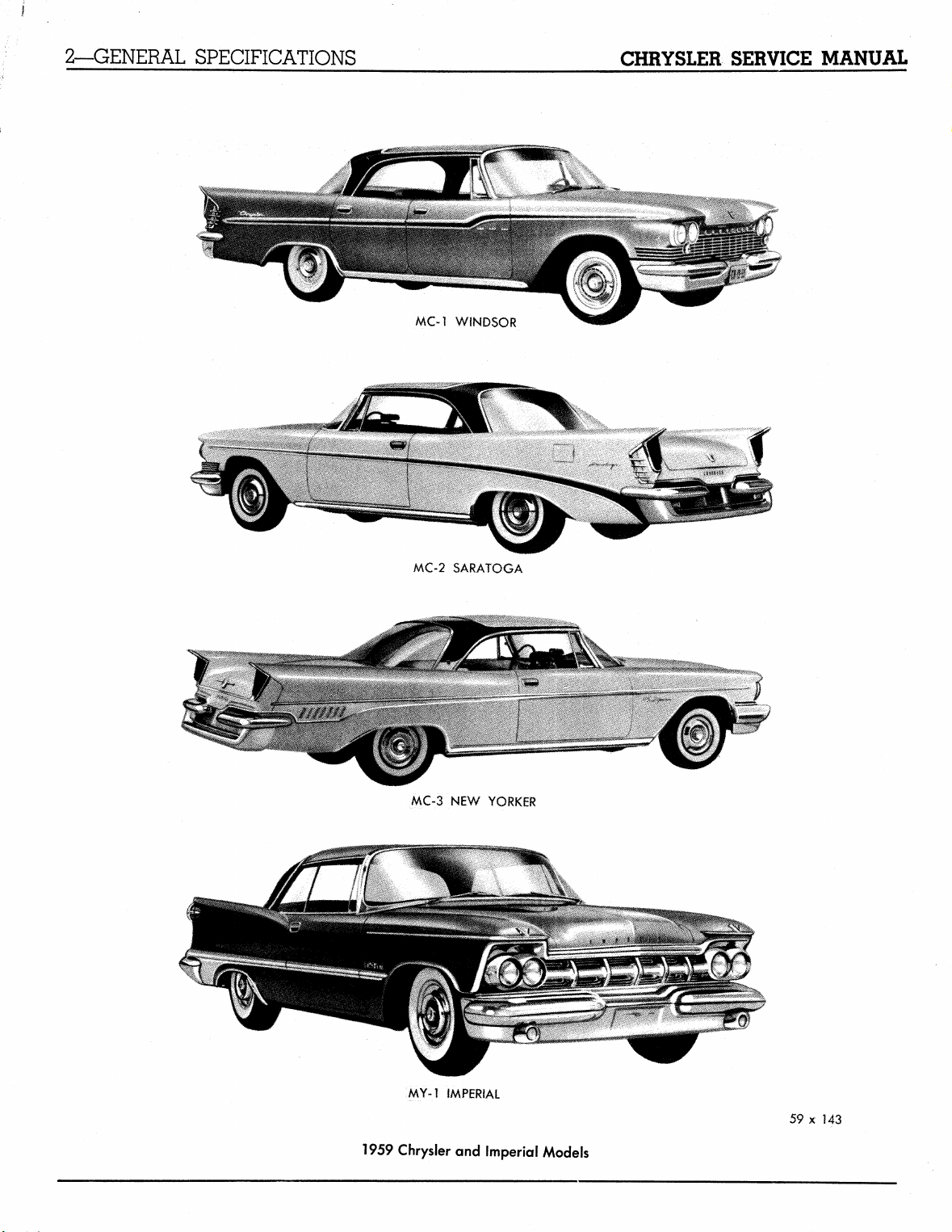
MC-l WINDSOR
MC-2 SARATOGA
MC-3 NEW YORKER
MY-1 fMPERiAL
1959 Chrysler and Imperial Models
59 x 143
MyMopar.com
Page 5
CHRYSLER SERVICE MANUAL
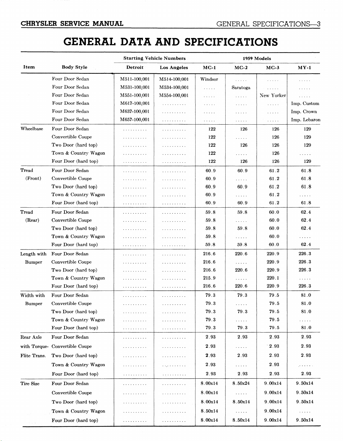
GENERAL DATA AND SPECIFICATIONS
GENERAL SPECIFICATIONS—3
Item Body Style
Four Door Sedan
Four Door Sedan
Four Door Sedan
Four Door Sedan
Four Door Sedan
Four Door Sedan
Wheelbase Four Door Sedan
Convertible Coupe
Two Door (hard top)
Town & Country Wagon
Four Door (hard top)
Tread Four Door Sedan
(Front) Convertible Coupe
Two Door (hard top)
Town & Country Wagon
Four Door (hard top)
Tread Four Door Sedan
(Rear) Convertible Coupe
Two Door (hard top)
Town & Country Wagon
Four Door (hard top)
Length with Four Door Sedan
Bumper Convertible Coupe
Two Door (hard top)
Town & Country Wagon
Four Door (hard top)
Width with Four Door Sedan
Bumper Convertible Coupe
Two Door (hard top)
Town & Country Wagon
Four Door (hard top)
Rear Axle Four Door Sedan
with Torque- Convertible Coupe
Flite Trans. Two Door (hard top)
Town & Country Wagon
Four Door (hard top)
Tire Size Four Door Sedan
Convertible Coupe
Two Door (hard top)
Town & Country Wagon
Four Door (hard top)
Starting Vehicle Numbers
Detroit
M511-100,001
M531-100,001
M551-100,001
M617-100,001
M637-100,001
M657-100,001
Los Angeles
M514-100,001
M534-100,001
M554-100,001
MC-1
Windsor
122
122
122
122
122
60.9
60.9
60.9
60.9
60.9
59.8
59.8
59.8
59.8
59.8
216.6
216.6
216.6
215.9
216.6
79.3
79.3
79.3
79.3
79.3
2.93
2.93
2.93
2.93
2.93
8.00x14
8.00x14
8.00x14
8.50x14
8.00x14
1959 Models
MC-2
Saratoga
126
126
126
60.9
60.9
60.9
59.8
59.8
59.8
220.6
220.6
220.6
79.3
79.3
79.3
2.93
2.93
2.93
8.50x24
8.50x14
8.50x14
MC-3
New Yorker
126
126
126
126
126
61.2
61.2
61.2
61.2
61.2
60.0
60.0
60.0
60.0
60.0
220.9
220.9
220.9
220.1
220.9
79.5
79.5
79.5
79.5
79.5
2.93
2.93
2.93
2.93
2.93
9.00x14
9.00x14
9.00x14
9.00x14
9.00x14
MyMopar.com
MY-1
Imp.
Imp.
Imp.
9.50x14
9.50x14
9.50x14
9.50x14
Custom
Crown
Lebaron
129
129
129
129
61.8
61.8
61.8
61.8
62.4
62.4
62.4
62.4
226.3
226.3
226.3
226.3
81.0
81.0
81.0
81.0
2.93
2.93
2.93
2.93
Page 6
4—SUSPENSION
CHRYSLER SERVICE MANUAL
Section I
SUSPENSION (FRONT SUSPENSION)
DATA AND SPECIFICATIONS
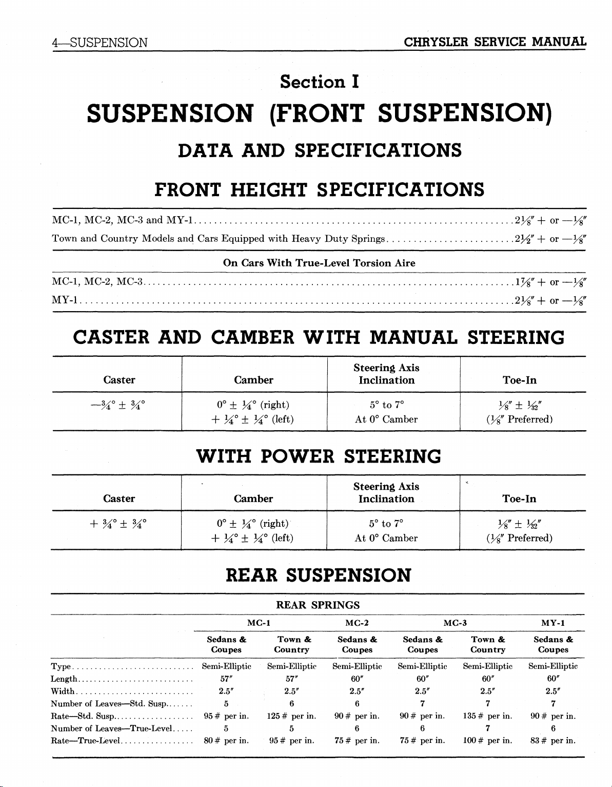
FRONT HEIGHT SPECIFICATIONS
MC-1,
MC-2, MC-3 and MY-1
Town and Country Models and Cars Equipped with Heavy Duty Springs
On Gars With True-Level Torsion Aire
MC-1,
MC-2,
MY-1
CASTER AND CAMBER WITH MANUAL STEERING
MC-3..
.iyg"+or
•
2Vs"+0T
Caster
~H° ± H°
Caster Camber
Type
Length
Width
Number of Leaves—Std. Susp
Rate—Std. Susp
Number of Leaves—True-Level. . .
Rate—True-Level
Steering Axis
Camber
0° ± M° (right)
+ H° ± H° (left)
Inclination
5° to 7°
At 0° Camber
(Vs"
WITH POWER STEERING
Steering Axis
Inclination
0°± M° (right)
Ji°.± M°(left)
5° to 7°
At 0° Camber
REAR SUSPENSION
REAR SPRINGS
MC-1
Sedans &
Coupes
Semi-Elliptic Semi-Elliptic Semi-Elliptic Semi-Elliptic Semi-Elliptic
57"
2.5"
5
95
# per in.
5
80 # per in.
Town &
Country
57"
2.5"
125
# per in.
95
# per in.
6
5
MC-2
Sedans &
Coupes
60"
2.5"
6
90
# per in.
6
75
# per in.
Sedans &
Coupes
60"
2.5"
7
90
# per in.
6
75
# per in.
MC-3
Town &
Country
60"
2.5"
135
# per in.
100
# per in.
7
7
Toe-In
y%
± w
Preferred)
Toe-In
± W
Preferred)
Semi-Elliptic
90
83
MY-1
Sedans &
Coupes
60"
2.5"
7
# per in.
6
# per in.
MyMopar.com
Page 7
CHRYSLER SERVICE
MANUAL
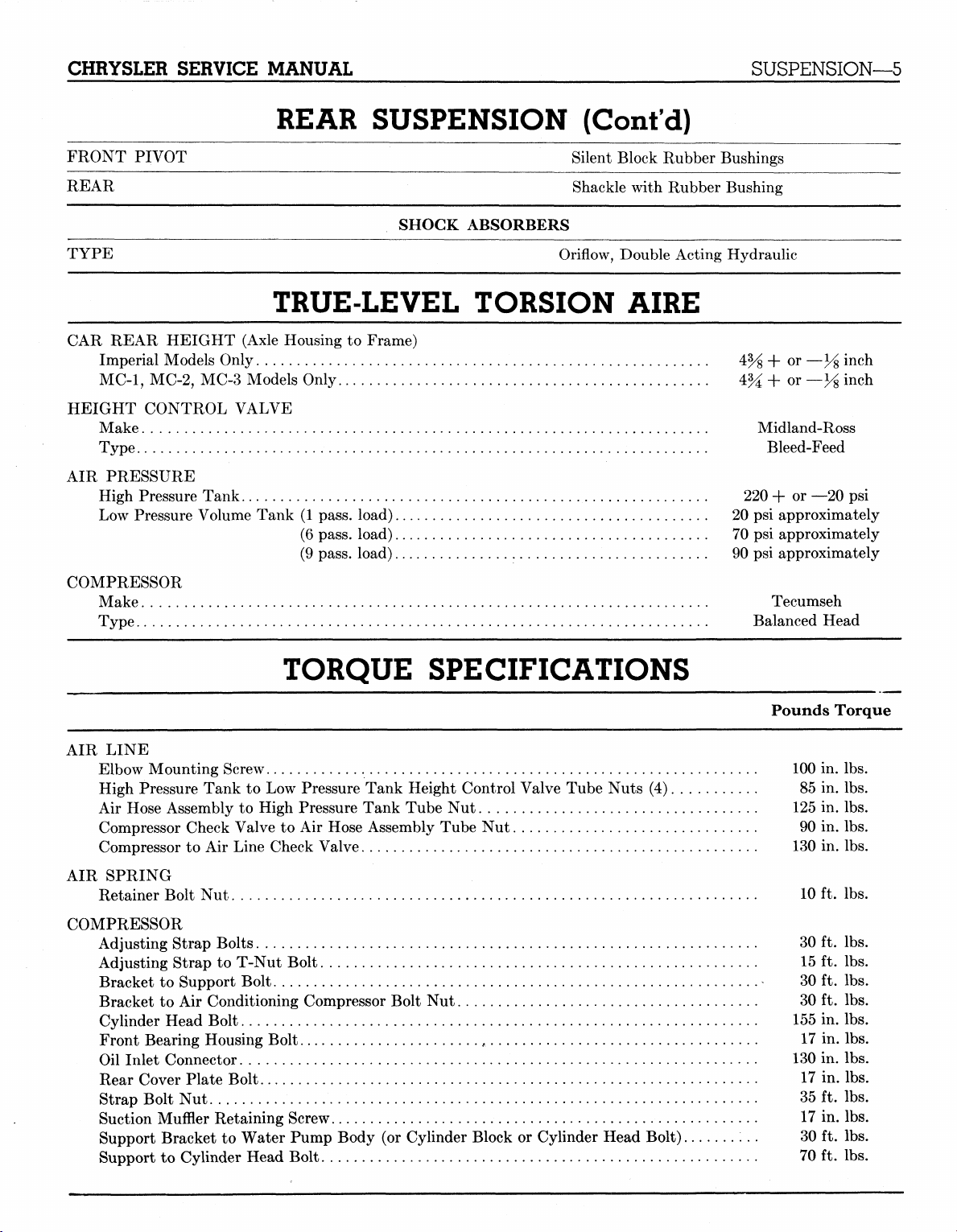
REAR SUSPENSION (Cont'd)
SUSPENSION—5
FRONT PIVOT
REAR
SHOCK ABSORBERS
TYPE
Silent Block Rubber'
Shackle with Rubber
Oriflow, Double Acting
Bushings
Bushing
Hydraulic
TRUE-LEVEL TORSION AIRE
CAR REAR HEIGHT (Axle Housing
Imperial Models Only
MC-1,
MC-2, MC-3 Models Only 4%
HEIGHT CONTROL VALVE
Make Midland-Ross
Type Bleed-Feed
AIR PRESSURE
High Pressure Tank 220
Low Pressure Volume Tank
COMPRESSOR
Make Tecumseh
Type Balanced Head
4% + or
to
Frame)
(1
pass, load)
(6 pass, load) 70
(9 pass, load)
20 psi
90 psi
+ or — y% inch
+ or
approximately
psi
approximately
approximately
—y% inch
—20
psi
TORQUE SPECIFICATIONS
AIR LINE
Elbow Mounting Screw 100
High Pressure Tank
Air Hose Assembly
Compressor Check Valve
Compressor
AIR SPRING
Retainer Bolt
COMPRESSOR
Adjusting Strap Bolts
Adjusting Strap
Bracket
Bracket
Cylinder Head Bolt 155
Front Bearing Housing Bolt
Oil Inlet Connector 130
Rear Cover Plate Bolt
Strap Bolt
Suction Muffler Retaining Screw
Support Bracket
Support
to Air
to
Support Bolt
to Air
Nut 35 ft. lbs.
to
Cylinder Head Bolt 70
to
Low Pressure Tank Height Control Valve Tube Nuts
to
High Pressure Tank Tube
to Air
Line Check Valve 130
Nut
10
30 ft. lbs.
to
T-Nut Bolt 15
30 ft. lbs.
Conditioning Compressor Bolt
17 in. lbs.
to
Water Pump Body
Hose Assembly Tube
f
17 in. lbs.
(or
Nut
125
Nut 90 in. lbs.
Nut 30 ft. lbs.
17 in. lbs.
Cylinder Block
or
Cylinder Head Bolt) 30
(4) 85 in. lbs.
Pounds Torque
in. lbs.
in. lbs.
in. lbs.
ft. lbs.
ft. lbs.
in. lbs.
in. lbs.
ft. lbs.
ft. lbs.
MyMopar.com
Page 8
6—SUSPENSION
CHRYSLER SERVICE MANUAL
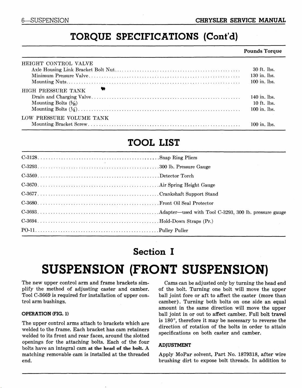
TORQUE SPECIFICATIONS (Cont'd)
HEIGHT CONTROL VALVE
Axle Housing Link Bracket Bolt
Minimum Pressure Valve 130
Mounting Nuts 100
Nut 30 ft. lbs.
Pounds Torque
in. lbs.
in. lbs.
HIGH PRESSURE TANK
Drain
and
Charging Valve 140 in.
Mounting Bolts (%>) 10
Mounting Bolts
LOW PRESSURE VOLUME TANK
Mounting Bracket Screw 100
(%)
*
100
TOOL LIST
C-3128 Snap Ring Pliers
C-3293 300
C-3569 Detector Torch
C-3670
C-3677 Crankshaft Support Stand
C-3680 Front
C-3693 Adapter—used with Tool C-3293,
C-3694 Hold-Down Straps
PO-11 Pulley Puller
Air
lb.
Pressure Gauge
Spring Height Gauge
Oil
Seal Protector
(Pr.)
300 lb.
lbs.
ft. lbs.
in. lbs.
in. lbs.
pressure gauge
SUSPENSION (FRONT SUSPENSION)
The
new
upper control
plify
the
method
Tool C-3669
trol arm bushings.
OPERATION (FIG.
The upper control arms attach
welded
welded
openings
bolts have
matching removable cam
end.
is
required
to the
to its
frame. Each bracket has cam retainers
front and rear faces, around
for the
an
integral
arm and
of
adjusting caster
for
installation
1)
attaching bolts. Each
cam at the
is
installed
frame brackets
and
of
upper con-
to
brackets which
the
of the
head
of the
at the
Section
sim-
camber.
are
slotted
four
bolt.
A
threaded
I
Cams can be adjusted only
of
the
bolt. Turning
ball joint fore
camber). Turning both bolts
amount
ball joint
is 180°, therefore
direction
specifications
ADJUSTMENT
Apply MoPar solvent, Part
brushing dirt
in the
or aft to
in or out to
of
rotation
on
to
one
bolt will move
affect
same direction will move
affect camber. Full bolt travel
it
may
be
necessary
of the
both caster
expose bolt threads.
bolts
No.
by
turning the head
the
the
caster (more than
on one
and
side
an
the
to
reverse
in
order
camber.
1879318, after wire
In
addition
to
MyMopar.com
end
upper
equal
upper
the
attain
to
Page 9
CHRYSLER SERVICE MANUAL
SUSPENSION—7
RONT ADJUSTING JOLT
59x120 *&' .•- mmi
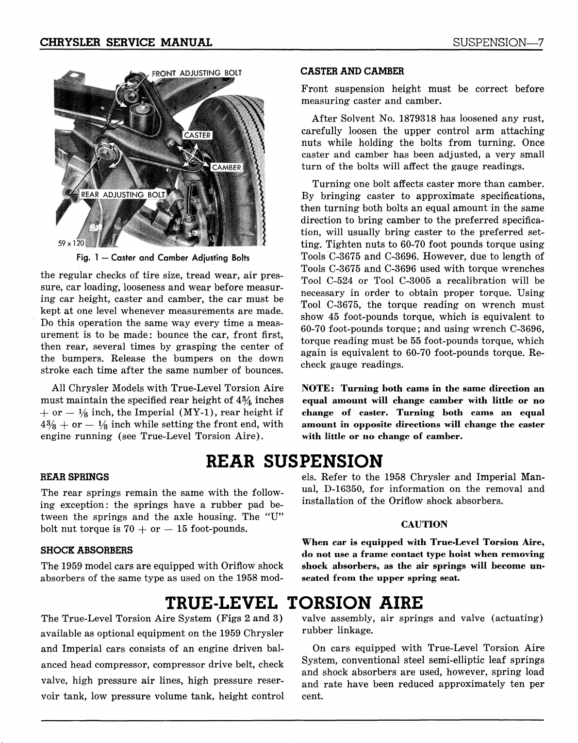
Fig.
1 — Caster and Camber Adjusting Bolts
the regular checks of tire size, tread wear, air pressure,
car loading, looseness and wear before measuring car height, caster and camber, the car must be
kept at one level whenever measurements are made.
Do this operation the same way every time a measurement is to be made: bounce the car, front first,
then rear, several times by grasping the center of
the bumpers. Release the bumpers on the down
stroke each time after the same number of bounces.
CASTER AND CAMBER
Front suspension height must be correct before
measuring caster and camber.
After Solvent No. 1879318 has loosened any rust,
carefully loosen the upper control arm attaching
nuts while holding the bolts from turning. Once
caster and camber has been adjusted, a very small
turn of the bolts will affect the gauge readings.
Turning one bolt affects caster more than camber.
By bringing caster to approximate specifications,
then turning both bolts an equal amount in the same
direction to bring camber to the preferred specification, will usually bring caster to the preferred setting. Tighten nuts to 60-70 foot pounds torque using
Tools C-3675 and C-3696. However, due to length of
Tools C-3675 and C-3696 used with torque wrenches
Tool C-524 or Tool C-3005 a recalibration will be
necessary in order to obtain proper torque. Using
Tool C-3675, the torque reading on wrench must
show 45 foot-pounds torque, which is equivalent to
60-70 foot-pounds torque; and using wrench C-3696,
torque reading must be 55 foot-pounds torque, which
again is equivalent to 60-70 foot-pounds torque. Recheck gauge readings.
All Chrysler Models with True-Level Torsion Aire
must maintain the specified rear height of 4% inches
-f or — i/8 inch, the Imperial (MY-1), rear height if
4%
+ or — % inch while setting the front end, with
engine running (see True-Level Torsion Aire).
REAR SUSPENSION
REAR SPRINGS
The rear springs remain the same with the following exception: the springs have a rubber pad between the springs and the axle housing. The "U"
bolt nut torque is 70 + or — 15 foot-pounds.
SHOCK ABSORBERS
The 1959 model cars are equipped with Oriflow shock
absorbers of the same type as used on the 1958 mod-
TRUE-LEVEL TORSION AIRE
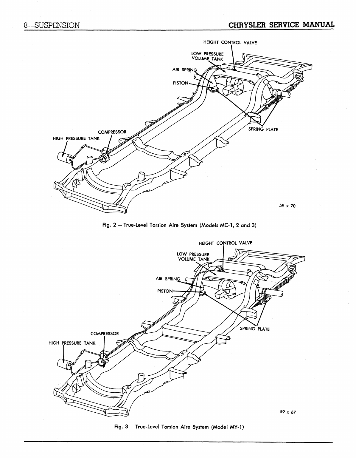
The True-Level Torsion Aire System (Figs 2 and 3)
available as optional equipment on the 1959 Chrysler
and Imperial cars consists of an engine driven bal-
anced head compressor, compressor drive belt, check
valve, high pressure air lines, high pressure reser-
voir tank, low pressure volume tank, height control
NOTE;
equal amount will change camber with little or no
change of caster. Turning both cams an equal
amount in opposite directions will change the caster
with little or no change of camber.
els.
ual,
Turning both cams in the same direction an
Refer to the 1958 Chrysler and Imperial Man-
D-16350, for information on the removal and
installation of the Oriflow shock absorbers.
CAUTION
When car is equipped with True-Level Torsion Aire,
do not use a frame contact type hoist when removing
shock absorbers, as the air springs will become unseated from the upper spring seat.
valve assembly, air springs and valve (actuating)
rubber linkage.
On cars equipped with True-Level Torsion, Aire
System, conventional steel semi-elliptic leaf springs
and shock absorbers are used, however, spring load
and rate have been reduced approximately ten per
cent.
MyMopar.com
Page 10
8—SUSPENSION
CHRYSLER SERVICE MANUAL
HEIGHT CONTROL VALVE
LOW PRESSURE
VOLUME TANK
AIR SPRING
PISTON.
HIGH PRESSURE TANK
COMPRESSOR
Fig.
2 - True-Level Torsion Aire System (Models MC-1, 2 and 3)
HEIGHT CONTROL VALVE
LOW PRESSURE
VOLUME TANK
SPRING PLATE
59 x 70
HIGH PRESSURE TANK
COMPRESSOR
Fig.
3 —True-Level Torsion Aire System (Model MY-1)
SPRING PLATE
59x67
MyMopar.com
Page 11
CHRYSLER SERVICE MANUAL
SUSPENSION—9
CHECK VALVE
PRESSURE LINE
SUCTION MUFFLER
59x75
OIL INLET LINE
CONNECTION
CYLINDER HEAD
VALVE PLATE
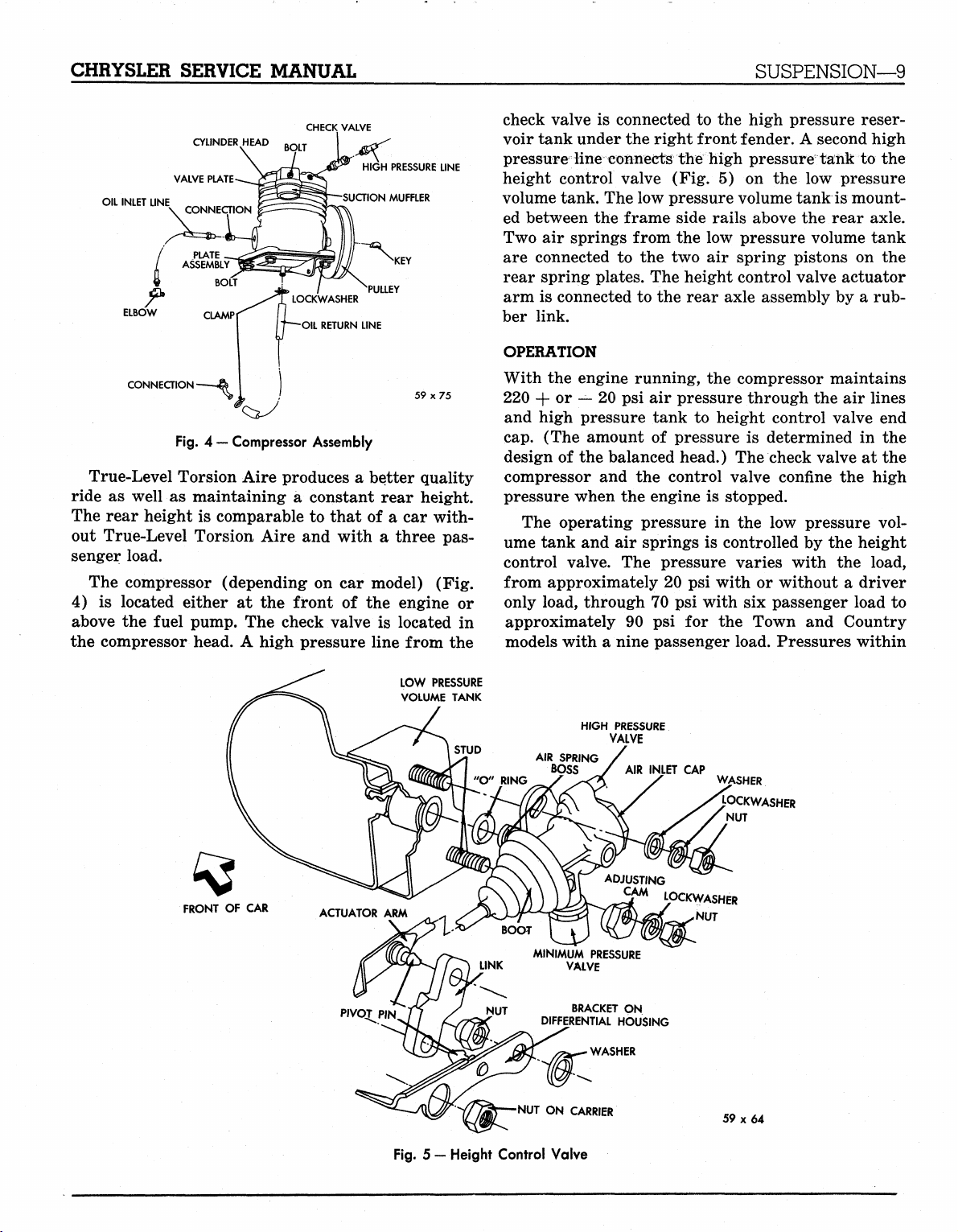
Fig.
4 — Compressor Assembly
True-Level Torsion Aire produces a better quality
ride as well as maintaining a constant rear height.
The rear height is comparable to that of a car without True-Level Torsion Aire and with a three passenger load.
The compressor (depending on car model) (Fig.
4) is located either at the front of the engine or
above the fuel pump. The check valve is located in
the compressor head. A high pressure line from the
check valve is connected to the high pressure reservoir tank under the right front fender. A second high
pressure line connects the high pressure" tank to the
height control valve (Fig. 5) on the low pressure
volume tank. The low pressure volume tank is mounted between the frame side rails above the rear axle.
Two air springs from the low pressure volume tank
are connected to the two air spring pistons on the
rear spring plates. The height control valve actuator
arm is connected to the rear axle assembly by a rubber link.
OPERATION
With the engine running, the compressor maintains
220 + or — 20 psi air pressure through the air lines
and high pressure tank to height control valve end
cap.
(The amount of pressure is determined in the
design of the balanced head.) The check valve at the
compressor and the control valve confine the high
pressure when the engine is stopped.
The operating pressure in the low pressure volume tank and air springs is controlled by the height
control valve. The pressure varies with the load,
from approximately 20 psi with or without a driver
only load, through 70 psi with six passenger load to
approximately 90 psi for the Town and Country
models with a nine passenger load. Pressures within
FRONT OF CAR
LOW PRESSURE
VOLUME TANK
HIGH PRESSURE
BRACKET ON
DIFFERENTIAL HOUSING
•NUT ON CARRIER
VALVE
ADJUSTING
CAM
LOCKWASHER
CAP
NUT
WASHER
LOCKWASHER
NUT
59x64
Fig.
5 —Height Control Valve
MyMopar.com
Page 12
10—SUSPENSION
CHRYSLER SERVICE MANUAL
this range vary instantly as the car moves over
chuck holes and expansion strips in the road surface,
in order to maintain the constant rear height. Since
these pressures are variable, it is not necessary to
test them.
The height control valve contains a minimum pres-
sure valve to maintain 8-15 psi in the air springs
SERVICE PROCEDURES
MAINTENANCE
The high pressure air tank (located under the right
front fender) should be drained at least once a
month. Depress the non-removable core in the drain
valve. (Should it ever be necessary to remove the
valve, remove the high pressure line at the check
valve FIRST.)
TESTING FOR LEAKS (Liquid Soap Method)
With the engine running, apply a diluted liquid soap
solution at the following locations where leaks would
cause bubbles: air springs and seats, height con-
trol valve mounting, air line connections, high pressure air tank, drain valve connection and outlet.
Stop the engine and remove the air line and check
valve from the compressor. Connect the air line and
check valve. Apply air pressure through the tank
drain valve. Coat check valve with soap solution. If
no leak is evident, wipe off soap solution before reinstallation.
Refrigerator Method (Refrigerant 12)
Add 150 pounds of weight to the center area of the
luggage compartment and raise car on a hoist. Discharge the high pressure tank by depressing the
valve core in the valve. Remove the minimum pressure valve from the height control valve. Disconnect
the rubber linkage from the differential housing
bracket and move the actuator arm manually to discharge all air from the low pressure volume tank.
With all air removed from the system, connect the
rubber linkage and install the minimum pressure
valve.
Install adaptor Tool C-3693 between the high
pressure air line and the compressor check valve.
Connect manifold gauge set, Tool C-3627 (used with
air conditioning) on adaptor, Tool C-3693, using
the gauge set suction hose. Attach the refrigerant
tank to the gauge set. Open the suction side of the
gauge set and charge the system with 40 psi of refrigerant 12. Shut off the gauge set and start the car
during a no-load operation as in changing tires by
use of a bumper jack. This pressure prevents damage to the air spring as the jack is lowered and a load
condition restored to the system.
The height control valve also contains a high pressure relief valve (150 psi) to protect the system
under extreme heavy load conditions.
engine. Operate the car engine until normal operat-
ing pressure of 200 + or — 20 psi is obtained.
Using leak detector, Tool C-3659, (used with air
conditioning) check the entire True-Level Torsion
Aire System for leaks and make all necessary repairs.
CAUTION
Be sure no gasoline is leaking from the car system
when checking the True-Level Torsion Aire System
with Tool C-3659.
With the car engine running, purge the refrigerant from the system by disconnecting the rubber
linkage from the differential housing and manually
operating the height control valve actuator arm.
With the refrigerant purged from the system, connect the rubber linkage to its bracket. Shut off the
car engine and again discharge all air from the high
pressure tank. Remove adaptor Tool C-3693 from
the air line and check valve. Connect the air line to
the check valve. Lower the hoist and remove the
weight from the luggage compartment. Operate the
car engine approximately three minutes before removing the car from the hoist.
CHECKING
The vehicle must have recommended tire pressures,
full tank of fuel (or equivalent weight added to luggage compartment over the tank). (Gasoline weighs
approximately 6% pounds per gallon.) The front
suspension height should be correct and equal on
both sides before placing car on level floor with no
passenger load.
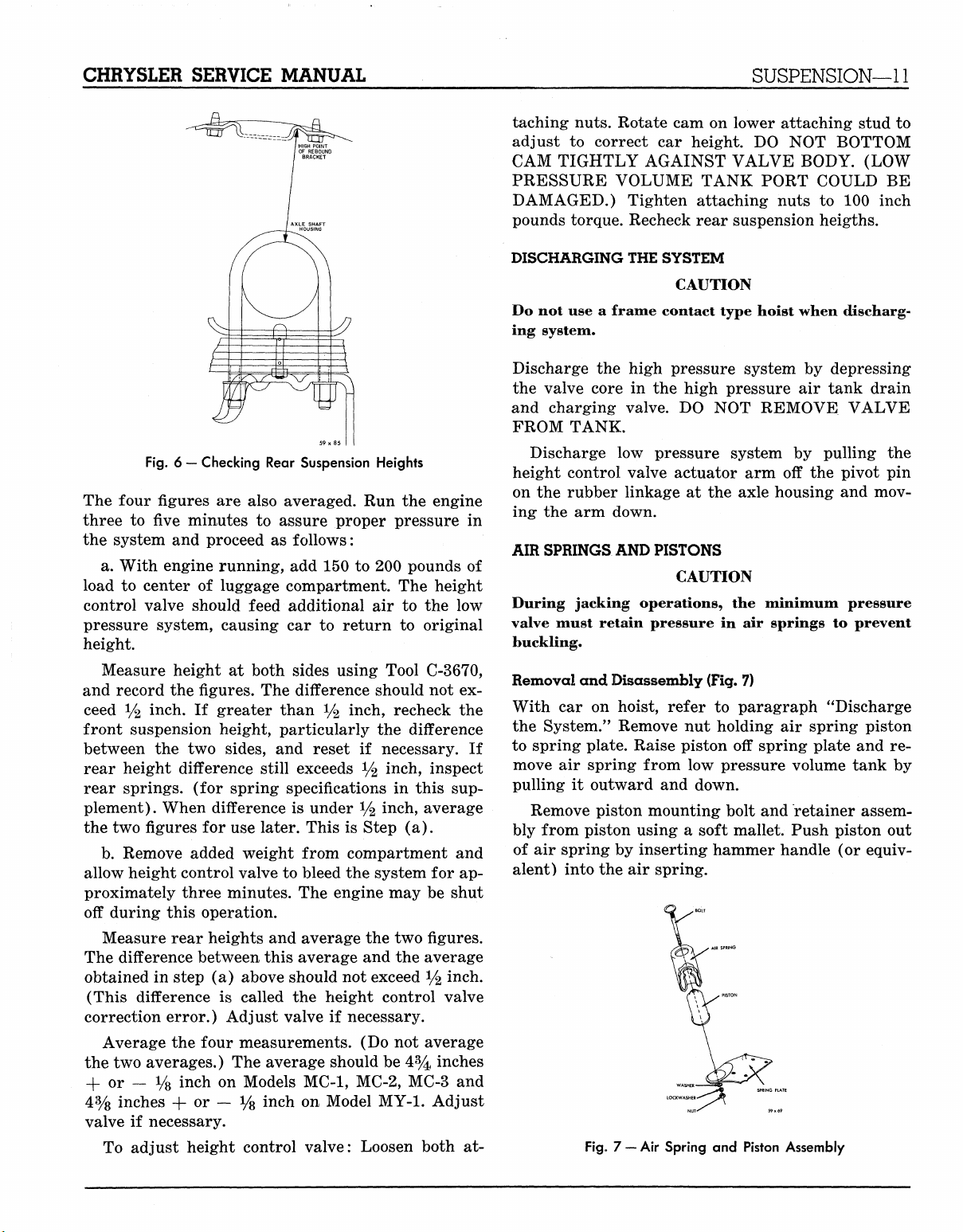
The rear suspension height must be set to a speci-
fied vertical distance between, the top of the axle
housing and highest part under the axle bumper
straps,
sides of the car (Fig. 6). Clean the bumper straps
and axle housing tubes before measuring.
Rear suspension height is measured (both sides)
twice, once with load and again without load. Both
pairs of figures are compared as well as averaged.
AND
ADJUSTING SUSPENSION HEIGHT
to the rear of the rubber bumpers on both
MyMopar.com
Page 13
CHRYSLER SERVICE MANUAL
SUSPENSION—11
taching nuts. Rotate cam on lower attaching stud to
adjust to correct car height. DO NOT BOTTOM
CAM TIGHTLY AGAINST VALVE BODY. (LOW
PRESSURE VOLUME TANK PORT COULD BE
DAMAGED.) Tighten attaching nuts to 100 inch
pounds torque. Recheck rear suspension heigths.
Fig. 6 — Checking Rear Suspension Heights
The four figures are also averaged. Run the engine
three to fiwe minutes to assure proper pressure in
the system and proceed as follows:
a. With engine running, add 150 to 200 pounds of
load to center of luggage compartment. The height
control valve should feed additional air to the low
pressure system, causing car to return to original
height.
Measure height at both sides using Tool C-3670,
and record the figures. The difference should not ex-
ceed */2 inch. If greater than % inch, recheck the
front suspension height, particularly the difference
between the two sides, and reset if necessary. If
rear height difference still exceeds */2 inch, inspect
rear springs, (for spring specifications in this supplement). When difference is under
y%
inch, average
the two figures for use later. This is Step (a).
b.
Remove added weight from compartment and
allow height control valve to bleed the system for approximately three minutes. The engine may be shut
off during this operation.
Measure rear heights and average the two figures.
The difference between this average and the average
obtained in step (a) above should not exceed % inch.
(This difference is called the height control valve
correction error.) Adjust valve if necessary.
Average the four measurements. (Do not average
the two averages.) The average should be 4% inches
+ or — y8 inch on Models MC-1, MC-2, MC-3 and
4%
inches -(-or — Vs inch on Model MY-1. Adjust
valve if necessary.
To adjust height control valve: Loosen both at-
DISCHARGING
THE
SYSTEM
CAUTION
Do not use a frame contact type hoist when discharging system.
Discharge the high pressure system by depressing
the valve core in the high pressure air tank drain
and charging valve. DO NOT REMOVE VALVE
FROM TANK.
Discharge low pressure system by pulling the
height control valve actuator arm off the pivot pin
on the rubber linkage at the axle housing and moving the arm down.
AIR SPRINGS
AND
PISTONS
CAUTION
During jacking operations, the minimum pressure
valve must retain pressure in air springs to prevent
buckling.
Removal and Disassembly
(Fig.
7)
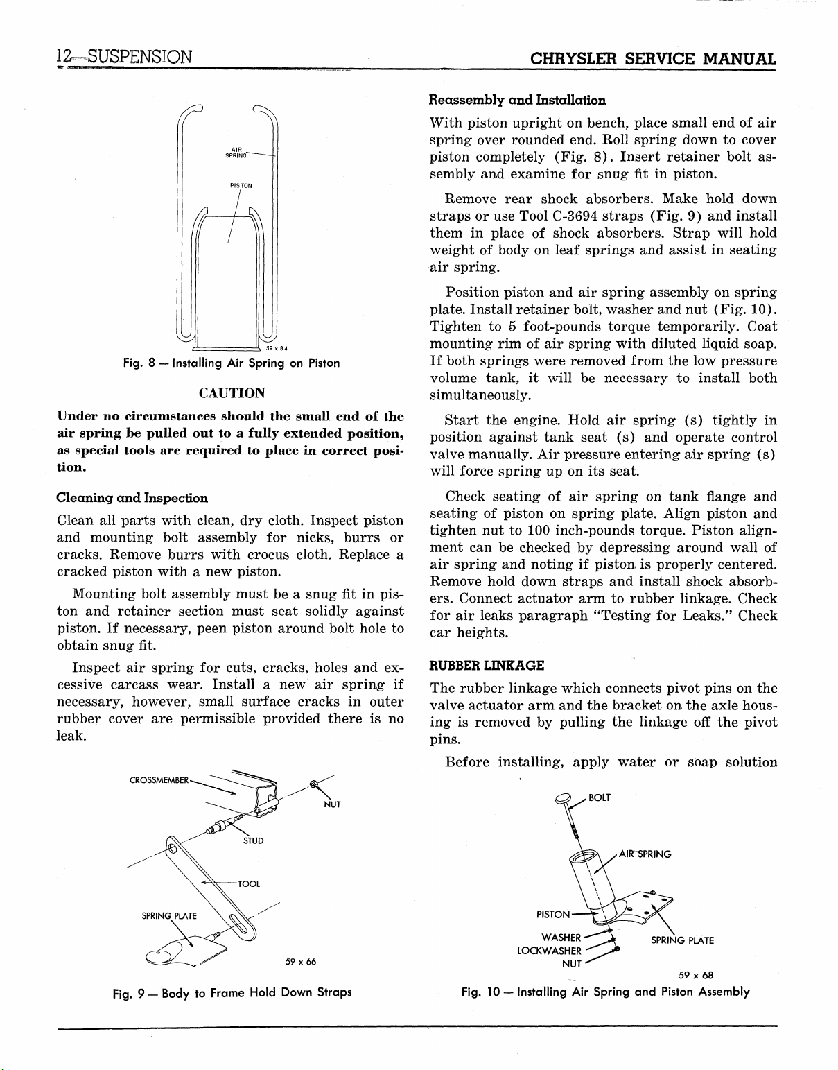
With car on hoist, refer to paragraph "Discharge
the System." Remove nut holding air spring piston
to spring plate. Raise piston off spring plate and re-
move air spring from low pressure volume tank by
pulling it outward and down.
Remove piston mounting bolt and retainer assembly from piston using a soft mallet. Push piston out
of air spring by inserting hammer handle (or equivalent) into the air spring.
Fig, 7 —
Air
Spring
and
Piston Assembly
MyMopar.com
Page 14
12—SUSPENSION
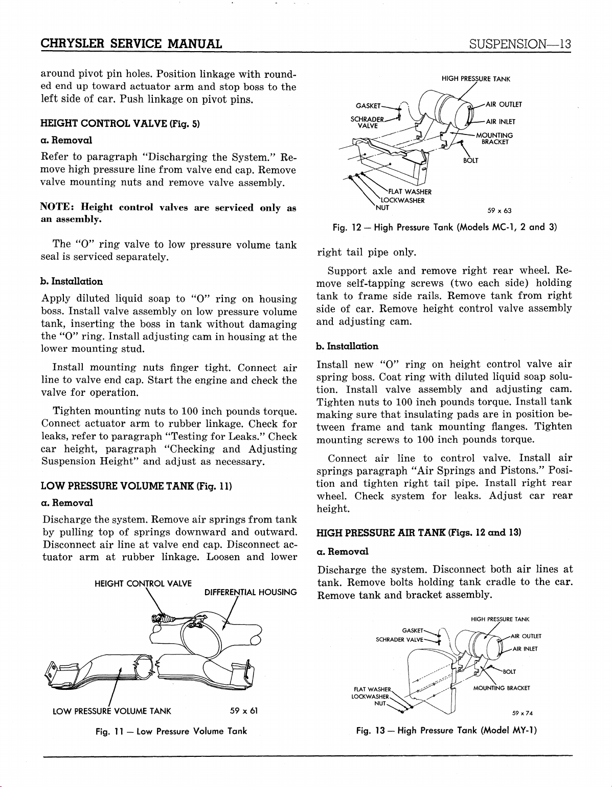
Fig.
8 — Installing Air Spring on Piston
CAUTION
Under no circumstances should the small end of the
air spring be pulled out to a fully extended position,
as special tools are required to place in correct position.
CHRYSLER SERVICE MANUAL
Reassembly and Installation
With piston upright on bench, place small end of air
spring over rounded end. Roll spring down to cover
piston completely (Fig. 8). Insert retainer bolt assembly and examine for snug fit in piston.
Remove rear shock absorbers. Make hold down
straps or use Tool C-3694 straps (Fig. 9) and install
them in place of shock absorbers. Strap will hold
weight of body on leaf springs and assist in seating
air spring.
Position piston and air spring assembly on spring
plate. Install retainer bolt, washer and nut (Fig. 10).
Tighten to 5 foot-pounds torque temporarily. Coat
mounting rim of air spring with diluted liquid soap.
If both springs were removed from the low pressure
volume tank, it will be necessary to install both
simultaneously.
Start the engine. Hold air spring (s) tightly in
position against tank seat (s) and operate control
valve manually. Air pressure entering air spring (s)
will force spring up on its seat.
Cleaning and Inspection
Clean all parts with clean, dry cloth. Inspect piston
and mounting bolt assembly for nicks, burrs or
cracks. Remove burrs with crocus cloth. Replace a
cracked piston with a new piston.
Mounting bolt assembly must be a snug fit in pis-
ton and retainer section must seat solidly against
piston. If necessary, peen piston around bolt hole to
obtain snug fit.
Inspect air spring for cuts, cracks, holes and ex-
cessive carcass wear. Install a new air spring if
necessary, however, small surface cracks in outer
rubber cover are permissible provided there is no
leak.
CROSSMEMBER
NUT
Check seating of air spring on tank flange and
seating of piston on spring plate. Align piston and
tighten nut to 100 inch-pounds torque. Piston alignment can be checked by depressing around wall of
air spring and noting if piston is properly centered.
Remove hold down straps and install shock absorbers.
Connect actuator arm to rubber linkage. Check
for air leaks paragraph "Testing for Leaks." Check
car heights.
RUBBER LINKAGE
The rubber linkage which connects pivot pins on the
valve actuator arm and the bracket on the axle hous-
ing is removed by pulling the linkage off the pivot
pins.
Before installing, apply water or soap solution
BOLT
AIRSPRING
59 x 66
Fig.
9 — Body to Frame Hold Down Straps
PISTON
WASHER
LOCKWASHER
Fig.
10 — Installing Air Spring and Piston Assembly
NUT
MyMopar.com
Page 15
CHRYSLER SERVICE MANUAL
SUSPENSION—13
around pivot
ed
end up
left side
HEIGHT CONTROL VALVE (Fig.
a. Removal
Refer
to
move high pressure line from valve
valve mounting nuts
NOTE:
pin
holes. Position linkage with round-
toward actuator
of car.
Push linkage
arm and
on
paragraph "Discharging
and
remove valve assembly.
Height control valves
stop boss
pivot pins.
5)
the
System."
end
are
serviced only
cap. Remove
an assembly.
The
"0"
ring valve
seal
is
serviced separately.
b.
Installation
Apply diluted liquid soap
boss.
Install valve assembly
tank, inserting
the
the "O" ring. Install adjusting
to low
boss
pressure volume tank
to "0"
on low
in
tank without damaging
ring
on
pressure volume
cam in
housing
lower mounting stud.
Install mounting nuts finger tight. Connect
line
to
valve
end
cap. Start
valve
for
operation.
Tighten mounting nuts
Connect actuator
leaks,
refer
arm to
to
paragraph "Testing
car height, paragraph "Checking
Suspension Height"
LOW PRESSURE VOLUME TANK (Fig.
a. Removal
Discharge
by pulling
Disconnect
tuator
the
top of
air
arm at
HEIGHT CONTROL VALVE
and
system. Remove
springs downward
line
at
rubber linkage. Loosen
the
engine
to 100
and
inch pounds torque.
rubber linkage. Check
for
Leaks." Check
and
adjust
as
necessary.
11)
air
springs from tank
and
valve
end cap.
Disconnect
DIFFERENTIAL HOUSING
Adjusting
and
to the
Re-
as
housing
at the
air
check
the
for
outward.
ac-
lower
HIGH PRESSURE TANK
AIR OUTLET
59x63
2 and 3)
Fig.
GASKET
SCHRADER
VALVE
'FLAT WASHER
\ NLOCKWASHER
NUT
12 -
High Pressure Tank (Models MC-1,
right tail pipe only.
Support axle
move self-tapping screws
tank
to
frame side rails. Remove tank from right
side
of car.
and adjusting
b.
Installation
Install
new "0"
and
remove right rear wheel.
(two
each side) holding
Re-
Remove height control valve assembly
cam.
ring
on
height control valve
air
spring boss. Coat ring with diluted liquid soap solu-
tion. Install valve assembly
Tighten nuts
to 100
inch pounds torque. Install tank
making sure that insulating pads
tween frame
mounting screws
Connect
springs paragraph
tion
and
wheel. Check system
and
tank mounting flanges. Tighten
to 100
air
line
to
"Air
tighten right tail pipe. Install right rear
for
and
adjusting
are in
cam.
position
inch pounds torque.
control valve. Install
Springs
and
Pistons." Posi-
leaks. Adjust
car
be-
air
rear
height.
HIGH PRESSURE AIR TANK (Figs. 12
a. Removal
Discharge
the
system. Disconnect both
tank. Remove bolts holding tank cradle
Remove tank
and
bracket assembly.
and 13)
air
to the car.
lines
at
LOW PRESSURE VOLUME TANK
Fig.
11 — Low
Pressure Volume Tank
59 x 61
GASKET
SCHRADER VALVE
FLAT WASHER
LOCKWASHER
NUT
Fig.
13 - High Pressure Tank (Model
HIGH PRESSURE TANK
AIR OUTLET
AIR INLET
BOLT
MOUNTING BRACKET
59x74
MY-1)
MyMopar.com
Page 16
14—SUSPENSION
CHRYSLER SERVICE MANUAL
SUCTION
MUFFLER
FELT
CYLINDER
BLOCK
SCREW
C3)
\
FRONT SEARING HOUSING
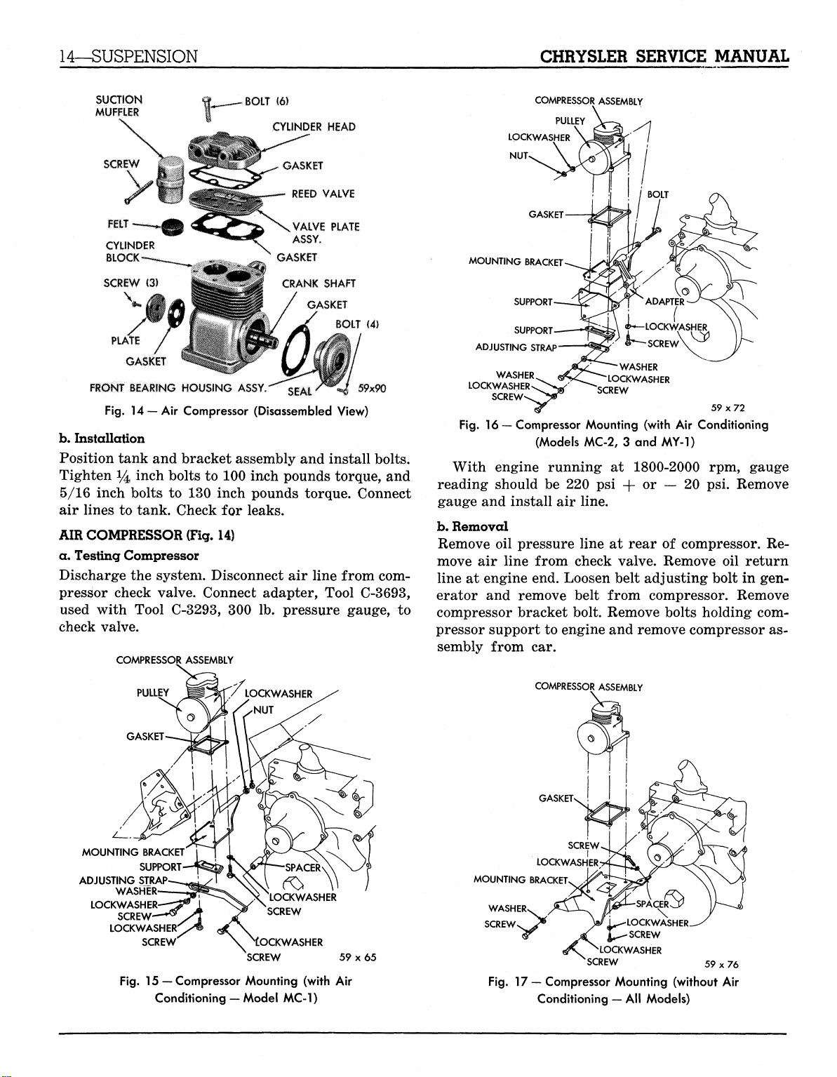
Fig.
14
—Air Compressor (Disassembled View)
b.
Installation
Position tank and bracket assembly and install bolts.
Tighten 14 i
5/16 inch bolts
ncn
bolts to 100 inch pounds torque, and
to
130 inch pounds torque. Connect
air lines to tank. Check
AIR COMPRESSOR (Fig.
for
14)
BOLT
ASSY.
leaks.
(6)
CYLINDER HEAD
^^
GASKET
REED VALVE
VALVE PLATE
ASSY.
GASKET
CRANK SHAFT
GASKET
SEAL'**
BOLT
59x90
(4)
a. Testing Compressor
Discharge the system. Disconnect
air
line from com-
pressor check valve. Connect adapter, Tool C-3693,
used with Tool C-3293,
300 lb.
pressure gauge,
to
check valve.
COMPRESSOR ASSEMBLY
COMPRESSOR ASSEMBLY
PULLEY
LOCKWASHER
NUT>
BOLT
MOUNTING BRACKET
SUPPORT
SUPPORT
ADJUSTING STRAP
WASHER
LOCKWASHER
Fig.
16 — Compressor Mounting (with Air Conditioning
(Models MC-2, 3 and MY-1)
With engine running
reading should
gauge and install
b.
Removal
Remove
move
line
erator
oil
air
at
engine end. Loosen belt adjusting bolt in gen-
and
be 220 psi
air
line.
pressure line
line from check valve. Remove
remove belt from compressor. Remove
i^LOCKWASHER
«^- SCREW
WASHER
LOCKWASHER
SCREW
at
1800-2000
or
+
at
rear
o
ADAPTER
—
20 psi.
of
compressor.
59x72
rpm,
Remove
oil
gauge
Re-
return
compressor bracket bolt. Remove bolts holding com-
pressor support to engine and remove compressor as-
sembly from
car.
PU
MOUNTING BRACKET
ADJUSTING STRAP
LOCKWASHER
SUPPORT
WASHER
SCREW
LOCKWASHERO^
SCREW
Fig.
15— Compressor Mounting (with Air
Conditioning — Model MC-1)
I I
LOCKWASHER
SCREW
OCKWASHER
SCREW
59x65
COMPRESSOR ASSEMBLY
GASKET
MOUNTING BRACKET
WASHER
SCREWS ^ Vi^
Fig.
17 —
Compressor Mounting (without
Conditioning
LOCKWASHER
JSCREW
*
LOCKWASHER
'SCREW
59x76
— All
Models)
-
Air
MyMopar.com
Page 17
CHRYSLER SERVICE MANUAL
SUSPENSION—15
c. Installation
(Figs.
15,16 and 17)
With compressor attached to support, attach support
to engine, tightening- bolts to 30 foot pounds torque.
Install compressor bracket. Tighten bolt to 30 foot
pounds torque.
Install belt (see "Accessory Belt Drives" in this
supplement for adjustment). Connect oil pressure
line,
air line and oil return line. Start engine and
check lines for leaks. Test air pressure.
COMPRESSOR RECONDITIONING
The following components parts are available for
service:
(1) Cylinder head and gasket
(2) Valve plate assembly and gasket
(3) Pulley and key
(4) Bottom plate, mounting plate and gasket
(5) Front bearing, housing and oil seal assembly
(6) Check valve assembly
(7) Suction muffler felt
CYLINDER HEAD AND/OR VALVE PLATE ASSEMBLY
Discharge the system. Remove air line from check
valve. Remove cylinder head bolts. Remove cylinder
head and valve plate assembly. If the plate does not
separate from the head, tap the plate lightly with a
soft mallet. Do not pry apart.
Clean piston heads, top of the cylinder block and
head bolt holes, cylinder head and valve plate, using
mineral spirits. Do not use scraper. Inspect pistons
and cylinder walls. If damaged, replace the compressor. If valve plate or cylinder head is damaged,
replace. Remove check valve only if replacement is
necessary.
Use new gaskets when installing valve plate and
cylinder head. Tighten bolts to 155 inch pounds
COMPRESSOR
59x91
TOOL
PULLEY
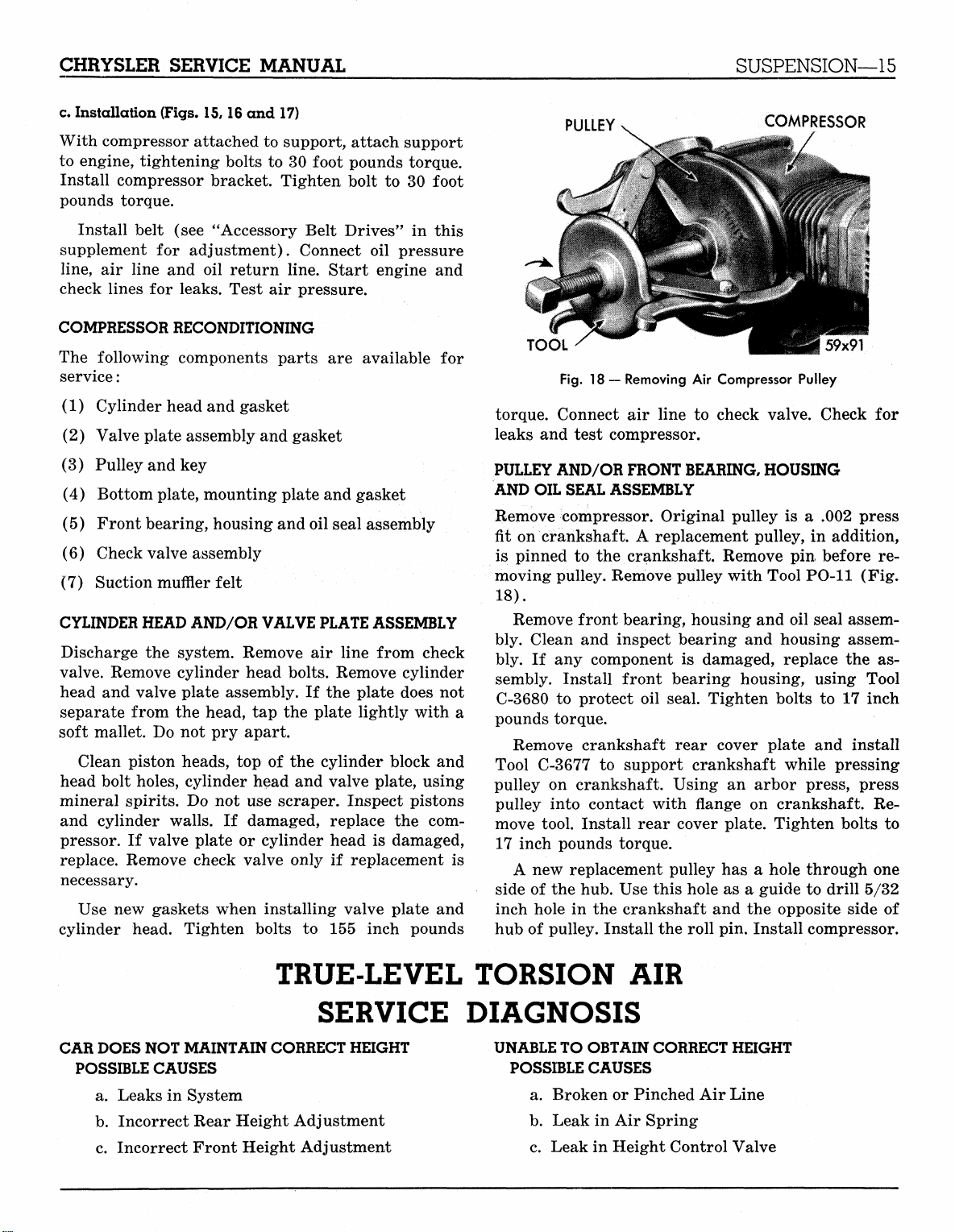
Fig.
18 — Removing Air Compressor Pulley
torque. Connect air line to check valve. Check for
leaks and test compressor.
PULLEY AND/OR FRONT BEARING, HOUSING
AND OIL SEAL ASSEMBLY
Remove compressor. Original pulley is a .002 press
fit on crankshaft. A replacement pulley, in addition,
is pinned to the crankshaft. Remove pin before re-
moving pulley. Remove pulley with Tool PO-11 (Fig.
18).
Remove front bearing, housing and oil seal assem-
bly. Clean and inspect bearing and housing assembly. If any component is damaged, replace the assembly. Install front bearing housing, using Tool
C-3680 to protect oil seal. Tighten bolts to 17 inch
pounds torque.
Remove crankshaft rear cover plate and install
Tool C-3677 to support crankshaft while pressing
pulley on crankshaft. Using an arbor press, press
pulley into contact with flange on crankshaft. Remove tool. Install rear cover plate. Tighten bolts to
17 inch pounds torque.
A new replacement pulley has a hole through one
side of the hub. Use this hole as a guide to drill 5/32
inch hole in the crankshaft and the opposite side of
hub of pulley. Install the roll pin. Install compressor.
TRUE-LEVEL TORSION AIR
CAR
DOES
NOT
MAINTAIN CORRECT
POSSIBLE
a. Leaks in System
b.
c. Incorrect Front Height Adjustment
CAUSES
Incorrect Rear Height Adjustment
SERVICE DIAGNOSIS
HEIGHT
UNABLE TO OBTAIN
POSSIBLE
a. Broken or Pinched Air Line
b.
c. Leak in Height Control Valve
CAUSES
Leak in Air Spring
CORRECT
HEIGHT
MyMopar.com
Page 18
16—AXLE—REAR
CHRYSLER SERVICE MANUAL
d. Fast Leak in Low Pressure Volume Tank
e. Height Control Valve Out of Adjustment
f. Rubber Linkage Loose or Broken at Differen-
tial
g. Broken Height Control Actuator Arm
LOW AIR PRESSURE
POSSIBLE CAUSES
a. Leak in Air Line
b.
Compressor Belt Broken or Out of Adjust-
ment
c. Slipping Drive Belt
d. Plugged Check Valve
REAR AXLE
DATA AND SPECIFICATIONS
e. Leaking Cylinder Head Gasket
f. Leaking Valve Plate Gasket
g. Cracked Cylinder Head
h. Worn Reed Valves
i. Excessive Cylinder Wall Wear
j.
EXCESSIVE AIR PRESSURE
POSSIBLE CAUSES
a. Carbon Build Up on Cylinder Head
b.
c. Excessive Oil on Top of Piston
Section II
Excessive Piston Ring Wear
Carbon Build Up on Pistons
MODELS MC-1, MC-2, MC-3, MY-1
TYPE Semi-Floating
GEAR TYPE -.. Hypoid
RINIG GEAR DIAMETER... 8.75 inch
PINON BEARING 2
TYPE .....: Tapered Roller
ADJUSTMENT Shim Pack
DIFFERENTIAL BEARINGS 2
TYPE Tapered Roller
ADJUSTMENT Threaded Adjuster
DRIVE GEAR AND PINION. Matched Sets
DRIVE GEAR RUNOUT .005 inch Maximum
DRIVE GEAR AND PINION BACKLASH. .006 to .008 inch
DIFFERENTIAL SIDE GEAR CLEARANCE .001 to .012 inch
MODELS MC-1, MC-2, MC-3, MY-1
Including Town
AXLE RATIO
Standard Ratio .. 2.93 to 1
Ratio with Air Conditioning 2.93 to 1
No.
of Drive Gear Teeth 41
No.
of Drive Pinion Teeth 14
8B
Country Models
WHEEL BEARINGS
Type. Tapered Roller
Adjustment Select Shims
Axle End Play .013 to .018 inch
MyMopar.com
Page 19
CHRYSLER SERVICE MANUAL
BRAKES—17
REAR AXLE
There is no basic design change in the rear axle and
sure grip differential except the larger diameter
pinion shaft is now used on all models for 1959. The
Service Procedures will remain the same on the Rear
Section
Axle and Sure Grip Differential as specified in the
1958 Chrysler and Imperial Service Manual, D-
16350.
III
BRAKES
DATA
MODELS
TYPE Total Contact (Floating Shoe) Hydraulic
DRUM DIAMETER
LINING
MC-1
... ,
Type Moulded Asbestos
Attachment Cyclebond
Width 2Y2 in.
Thickness
l
AND
SPECIFICATIONS
MC-2, MC-3,
11
in.
12
%i
MY-1
in.
in-
BRAKE SHOE RETURN SPRING TENSION USING
FISH SCALE HOOKED
BRAKE PEDAL FREE PLAY
WHEEL CYLINDER BORE
Front—Upper
Rear
1K mMASTER CYLINDER BORE V/% in.
PISTON CLEARANCE .003
and
AT TOE OF
% in. to J^ in.
Lower 1%
SHOE 35
to
45 lbs. required
between shoe
(in models with Power Brakes)
in. to
to
break contact
and
push
in.
.0065
in.
HAND BRAKE
MODELS MC-1, MC-2, MC-3,
TYPE Internal Expanding
LOCATION Propeller Shaft
DRUM DIAMETER.
LINING TYPE
Length 13.06 inch
Width
2 in.
Thickness
Clearance .015
%
7
,
Moulded
at
Rear
inch
and
Compressed Asbestos
m
in. to
MY-1
of
Transmission
-
.020
in.
MyMopar.com
rod
Page 20
18—BRAKES
CHRYSLER SERVICE MANUAL
TOTAL CONTACT SERVICE BRAKES
Servicing procedures outlined in the 1958 Chrysler
and Imperial Service Manual, D-16350, will apply
to the 1959 models with the exception of the removal
and installation of the new brake shoe retainer.
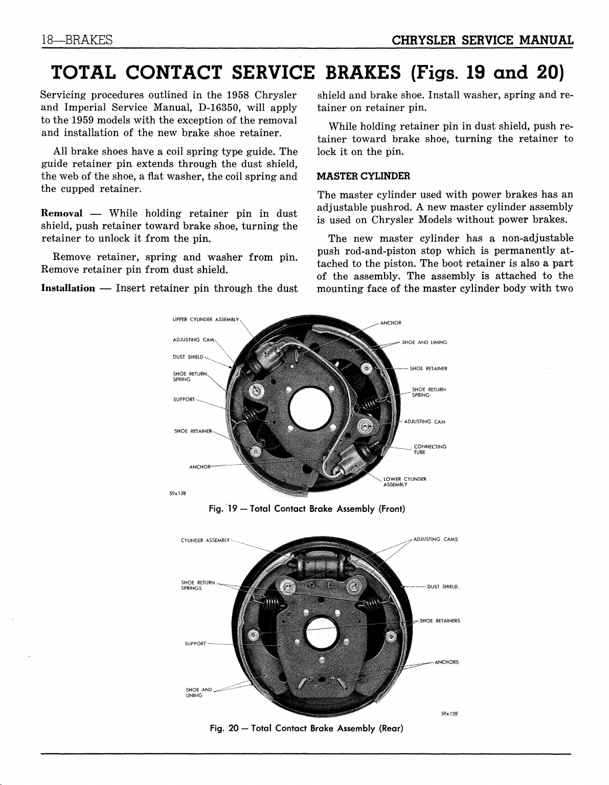
All brake shoes have a coil spring type guide. The
guide retainer pin extends through the dust shield,
the web of the shoe, a flat washer, the coil spring and
the cupped retainer.
Removal — While holding retainer pin in dust
shield, push retainer toward brake shoe, turning the
retainer to unlock it from the pin.
Remove retainer, spring and washer from pin.
Remove retainer pin from dust shield.
Installation — Insert retainer pin through the dust
UPPER CYLINDER
ADJUSTING
CAM
DUST SHIELD-v.
SHOE RETURN
SPRING
SUPPORT-^
shield and brake shoe. Install washer, spring and retainer on retainer pin.
While holding retainer pin in dust shield, push retainer toward brake shoe, turning the retainer to
lock it on the pin.
MASTER CYLINDER
The master cylinder used with power brakes has an
adjustable pushrod. A new master cylinder assembly
is used on Chrysler Models without power brakes.
The new master cylinder has a non-adjustable
push rod-and-piston stop which is permanently attached to the piston. The boot retainer is also a part
of the assembly. The assembly is attached to the
mounting face of the master cylinder body with two
(Figs.
.- SHOE
AND
UNING
— SHOE RETAINER
SHOE RETURN
:
SPRING
19 and 20)
SHOE RETAINE
CYLINDER ASSEMBLY
SHOE
RE'
SPRINGS
SUPPORT
SHOE AND
LINING
Fig.
19
—Total Contact Brake Assembly (Front)
^**z~~-
-ADJUSTING
CONNECTING
TUBE
LOWfi? CYLINDER
ADJUSTING CAMS
CAM
DUST SHIELD
SHOE RETAINERS
ANCHORS
Fig.
20 — Total Contact Brake Assembly (Rear)
MyMopar.com
Page 21
CHRYSLER SERVICE MANUAL
BRAKES—19
screws. No attempt should be made to disassemble
this push rod and piston.
The combined action of the piston return spring
and the pressure in the master cylinder is sufficient
to hold the brake pedal in the "off" position, without
a pedal return spring and pedal stop. The brake
pedal should never be pulled back beyond the limit
controlled by the piston stop. A minimum pull of 50
pounds could pull the piston off the push rod.
PISTON TYPE POWER BRAKE UNIT
The 1959 Chrysler and Imperial Models will have
both the "Bellows Type" Power Brake as well as the
"Piston, Type." The servicing procedure for the "Bellows Type" is the same as that in the 1958 Chrysler
and Imperial Service Manual. The servicing procedure for the "Piston Type" is outlined below:
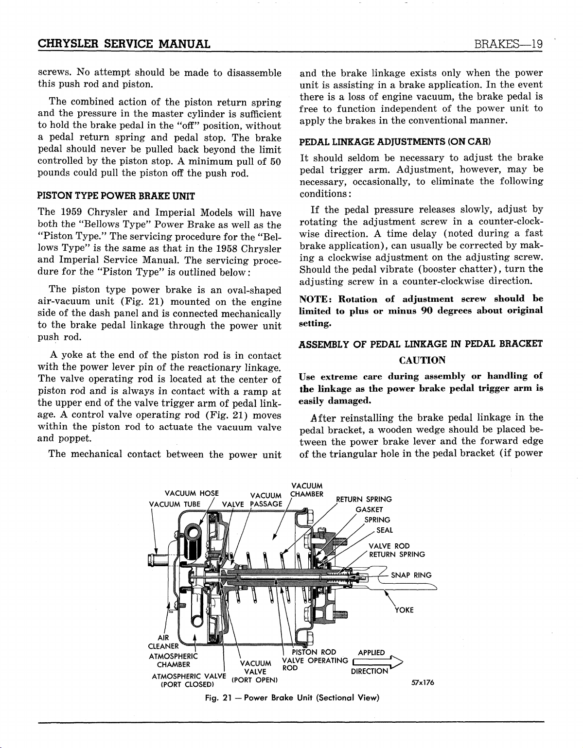
The piston type power brake is an oval-shaped
air-vacuum unit (Fig. 21) mounted on the engine
side of the dash panel and is connected mechanically
to the brake pedal linkage through the power unit
push rod.
A yoke at the end of the piston rod is in contact
with the power lever pin of the reactionary linkage.
The valve operating rod is located at the center of
piston rod and is always in contact with a ramp at
the upper end of the valve trigger arm of pedal linkage.
A control valve operating rod (Fig. 21) moves
within the piston rod to actuate the vacuum valve
and poppet.
The mechanical contact between the power unit
and the brake linkage exists only when the power
unit is assisting in a brake application. In the event
there is a loss of engine vacuum, the brake pedal is
free to function independent of the power unit to
apply the brakes in the conventional manner.
PEDAL LINKAGE ADJUSTMENTS (ON CAR)
It should seldom be necessary to adjust the brake
pedal trigger arm. Adjustment, however, may be
necessary, occasionally, to eliminate the following
conditions:
If the pedal pressure releases slowly, adjust by
rotating the adjustment screw in a counter-clockwise direction. A time delay (noted during a fast
brake application), can usually be corrected by mak-
ing a clockwise adjustment on the adjusting screw.
Should the pedal vibrate (booster chatter), turn the
adjusting screw in a counter-clockwise direction.
NOTE: Rotation of adjustment screw should be
limited to plus or minus 90 degrees about original
setting.
ASSEMBLY OF PEDAL LINKAGE IN PEDAL BRACKET
CAUTION
Use extreme care during assembly or handling of
the linkage as the power brake pedal trigger arm is
easily damaged.
After reinstalling the brake pedal linkage in the
pedal bracket, a wooden wedge should be placed between the power brake lever and the forward edge
of the triangular hole in the pedal bracket (if power
VACUUM HOSE VACUUM CHAMBER
VACUUM TUBE / VALVE PASSAGE
AIR
CLEANER
ATMOSPHERIC
CHAMBER
ATMOSPHERIC VALVE
(PORT CLOSED)
Fig.
VACUUM
VALVE
(PORT OPEN)
21
—Power Brake Unit (Sectional View)
/
VALVE OPERATING
ROD
VACUUM
RETURN SPRING
GASKET
SPRING
SEAL
VALVE
RETURN SPRING
£
DIRECTION
ROD
57x176
MyMopar.com
Page 22
20—BRAKES
CHRYSLER SERVICE MANUAL
ARBOR f-<
(TOOL) ^
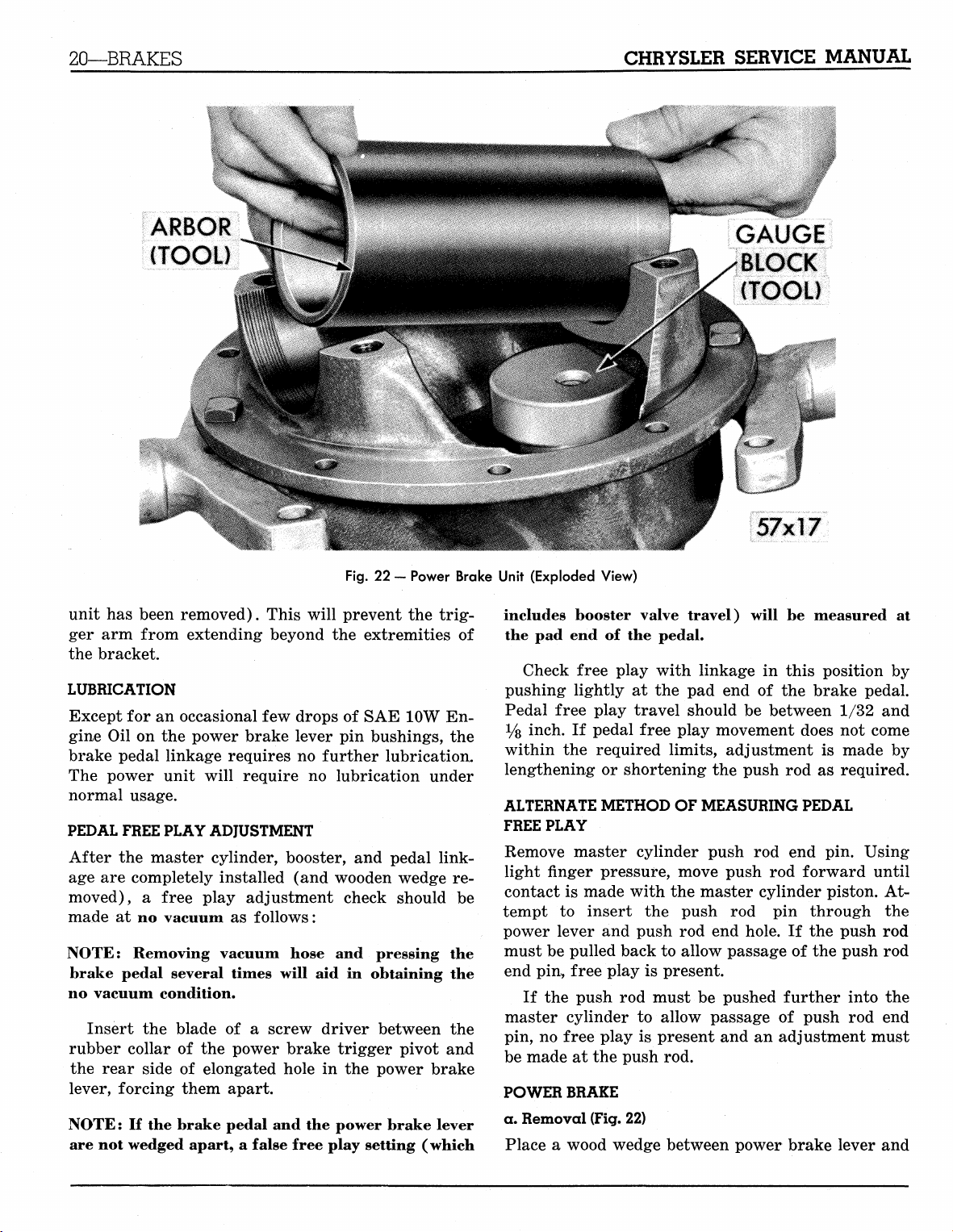
Fig.
22 - Power Brake Unit (Exploded View)
unit has been removed). This will prevent the trigger arm from extending beyond the extremities of
the bracket.
LUBRICATION
Except for an occasional few drops of SAE 10W Engine Oil on the power brake lever pin bushings, the
brake pedal linkage requires no further lubrication.
The power unit will require no lubrication under
normal usage.
PEDAL FREE PLAY ADJUSTMENT
After the master cylinder, booster, and pedal linkage are completely installed (and wooden wedge removed), a free play adjustment check should be
made at no vacuum as follows:
NOTE: Removing vacuum hose and pressing the
brake pedal several times will aid in obtaining the
no vacuum condition.
Insert the blade of a screw driver between the
rubber collar of the power brake trigger pivot and
the rear side of elongated hole in the power brake
lever, forcing them apart.
NOTE: If the brake pedal and the power brake lever
are not wedged apart, a false free play setting (which
GAUGE
BLOCK
(TOOL)
57x17
includes booster valve travel) will be measured at
the pad end of the pedal.
Check free play with linkage in this position by
pushing lightly at the pad end of the brake pedal.
Pedal free play travel should be between 1/32 and
Vs inch. If pedal free play movement does not come
within the required limits, adjustment is made by
lengthening or shortening the push rod as required.
ALTERNATE METHOD OF MEASURING PEDAL
FREE PLAY
Remove master cylinder push rod end pin. Using
light finger pressure, move push rod forward until
contact is made with the master cylinder piston. Attempt to insert the push rod pin through the
power lever and push rod end hole. If the push rod
must be pulled back to allow passage of the push rod
end pin, free play is present.
If the push rod must be pushed further into the
master cylinder to allow passage of push rod end
pin, no free play is present and an adjustment must
be made at the push rod.
POWER BRAKE
a. Removal (Fig. 22)
Place a wood wedge between power brake lever and
MyMopar.com
Page 23
CHRYSLER SERVICE MANUAL
BRAKES—21
forward edge
prevent trigger
ities
of
NOTE:
hole
If
in
of
triangular hole
arm
bracket.
pedal linkage
dash panel
from extending beyond extrem-
the
trigger
Disconnect vacuum hose
attaching bolts
at
dash panel
power unit assembly.
NOTE: Use care
cross
pin.
b.
Disassembly
Scribe across flange
guide
to
correct assembly (Fig.
NOTE:
Do not
to
prevent loss
of
clamp yoke
tion.
Remove
ing
the
the
cylinder shell
vacuum hose from
CAUTION
The vacuum tube must
(Fig.
4).
diaphragm
Make certain
is in the
the
annular groove
plate assembly.
Install valve
rod
poppet
NOTE: Before installing
the following test.
Depress
to blow through
through
the
valve
the
the
hose indicates
rod and at the
vacuum hose. Failure
properly seated.
VACUUM CYLINDER
AIR CLEANER
COVER
AIR CLEANER
HAIR
NUT (4)
in
pedal bracket,
is
allowed
to
extend through
arm may be
at
power unit. Remove
and
carefully remove
cylinder
of the
and end
pedal linkage
23).
in
vise during any opera-
and
gasket, disconnect-
the air
be in the
bead
cleaner cover.
lowest quadrant
at
outer diameter
of the
and
applying diaphragm.
the
vacuum cylinder, make
same time,
the
poppet assembly
END PLATE
MATING MARKS
damaged.
plate
as a
tube
and
try
to
blow
GASKET
to
of
is
END PLATE SPRING ROD
RETAINER PLATE
POPPET DIAPHRAGM
APPLYING
DIAPHRAGM
VALVE
ROD
APPLYING
SCREW
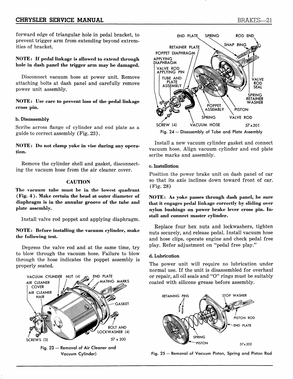
Fig.
Install
PIN
TUBE
AND
PLATE
ASSEMBLY
(4)
24
— Disassembly
a new
SPRING VALVE
VACUUM HOSE 57x201
of
Tube
and
vacuum cylinder gasket
vacuum hose. Align vacuum cylinder
scribe marks
and
assembly.
END
SPRING
RETAINER
WASHER
PISTON
ROD
Plate Assembly
and
and end
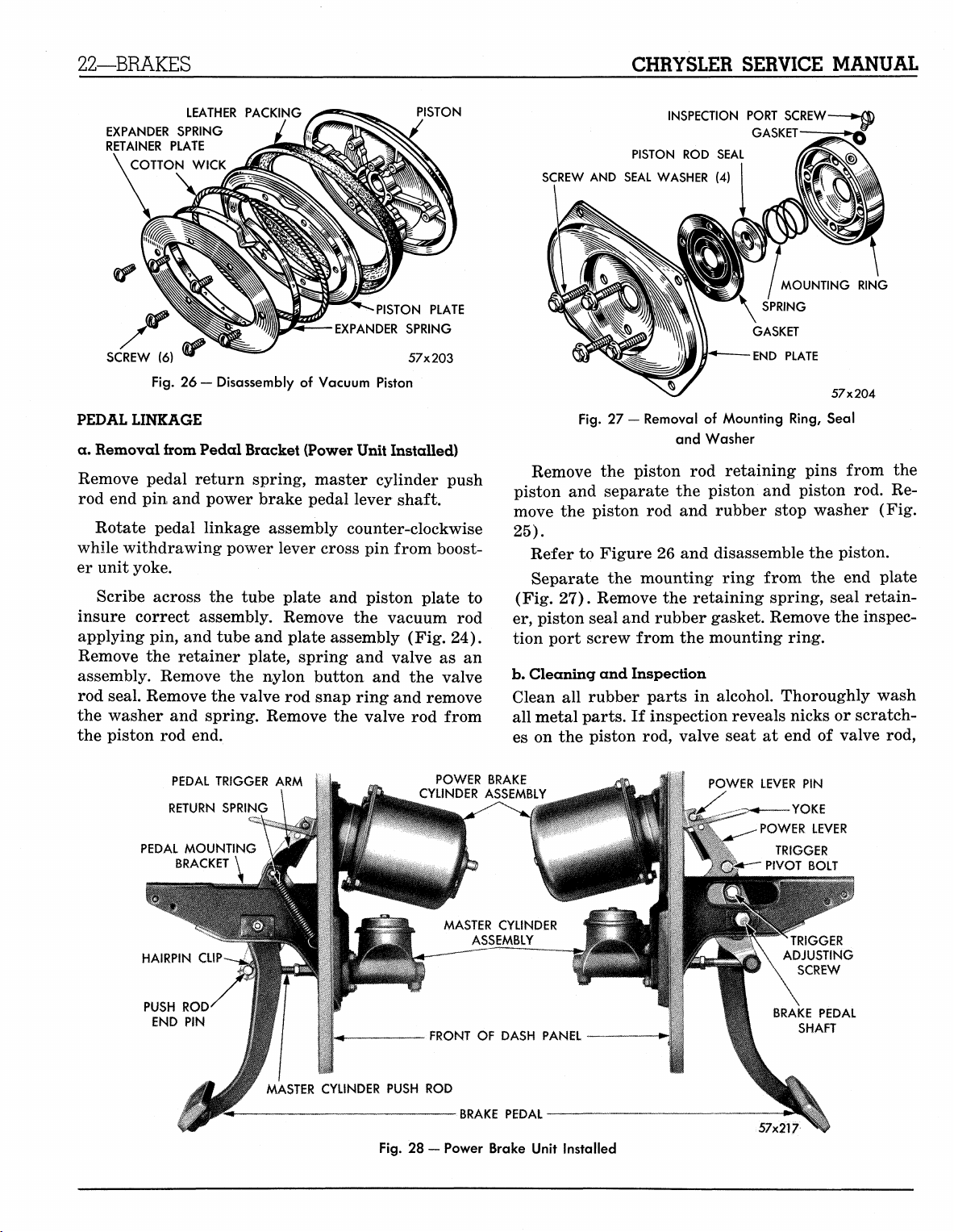
c. Installation
Position
so that
(Fig.
NOTE:
that
nylon bushings
stall
nuts securely,
and hose clips, operate engine
play. Refer adjustment
the
power brake unit
its
axis inclines down toward front
28)
As
yoke passes through dash panel,
it
engages pedal linkage correctly
on
power brake lever cross
and
connect master cylinder.
Replace four
hex
nuts
and
and
release pedal. Install vacuum hose
on
"pedal free play."
on
dash panel
by
sliding over
lockwashers, tighten
and
check pedal free
d. Lubrication
The power unit will require
normal use.
or repair,
If the
all
unit
oil seals
is
and
no
lubrication under
disassembled
for
"0" rings must be suitably
coated with silicone grease before assembly.
RETAINING PINS
STOP WASHER
VALVE
ROD
SEAL
connect
plate
of car
of car.
be
sure
pin. In-
overhaul
SCREWS
LOCKWASHER
(3)
Fig.
23 — Removal of Air Cleaner and
Vacuum Cylinder)
BOLT
57 x 200
AND
(4)
PISTON
ROD
END PLATE
57x202
Fig.
25 — Removal of Vacuum Piston, Spring and Piston Rod
MyMopar.com
Page 24
22—BRAKES
CHRYSLER SERVICE MANUAL
LEATHER PACKING
EXPANDER SPRING
RETAINER PLATE
COTTON WICK
EXPANDER SPRING
SCREW
(6) W 57x203
Fig.
26
— Disassembly
of
Vacuum Piston
PISTON
PISTON PLATE
PEDAL LINKAGE
a. Removal from Pedal Bracket (Power Unit Installed)
Remove pedal return spring, master cylinder push
rod end pin and power brake pedal lever shaft.
Rotate pedal linkage assembly counter-clockwise
while withdrawing power lever cross pin from booster unit yoke.
Scribe across the tube plate and piston plate to
insure correct assembly. Remove the vacuum rod
applying pin, and tube and plate assembly (Fig. 24).
Remove the retainer plate, spring and valve as an
assembly. Remove the nylon button and the valve
rod seal. Remove the valve rod snap ring and remove
the washer and spring. Remove the valve rod from
the piston rod end.
INSPECTION PORT SCREW
GASKET
PISTON
ROD
SEAL
SCREW
AND
SEAL WASHER
Fig.
27 —
Removal
(4)
GASKET
END PLATE
of
Mounting Ring, Seal
and Washer
MOUNTING RING
SPRING
57x204
Remove the piston rod retaining pins from the
piston and separate the piston and piston rod. Remove the piston rod and rubber stop washer (Fig.
25).
Refer to Figure 26 and disassemble the piston.
Separate the mounting ring from the end plate
(Fig. 27). Remove the retaining spring, seal retainer, piston seal and rubber gasket. Remove the inspection port screw from the mounting ring.
b.
Cleaning and Inspection
Clean all rubber parts in alcohol. Thoroughly wash
all metal parts. If inspection reveals nicks or scratches on the piston rod, valve seat at end of valve rod,
PEDAL TRIGGER
RETURN SPRING
PEDAL MOUNTING
BRACKET
PUSH
ROD
END
PIN
!
^ . MASTER CYLINDER PUSH
ARM
\
POWER BRAKE
CYLINDER ASSEMBLY
MASTER CYLINDER
FRONT
ROD
Fig.
28 —
Power Brake Unit Installed
ASSEMBLY
OF
DASH PANEL
W
:
POWER LEVER
•——YOKE
POWER LEVER
TRIGGER
*~^" PIVOT BOLT
ADJUSTING
BRAKE PEDAL
MyMopar.com
PIN
TRIGGER
SCREW
SHAFT
Page 25

CHRYSLER SERVICE MANUAL
ACCESSORY BELT DRIVES—23
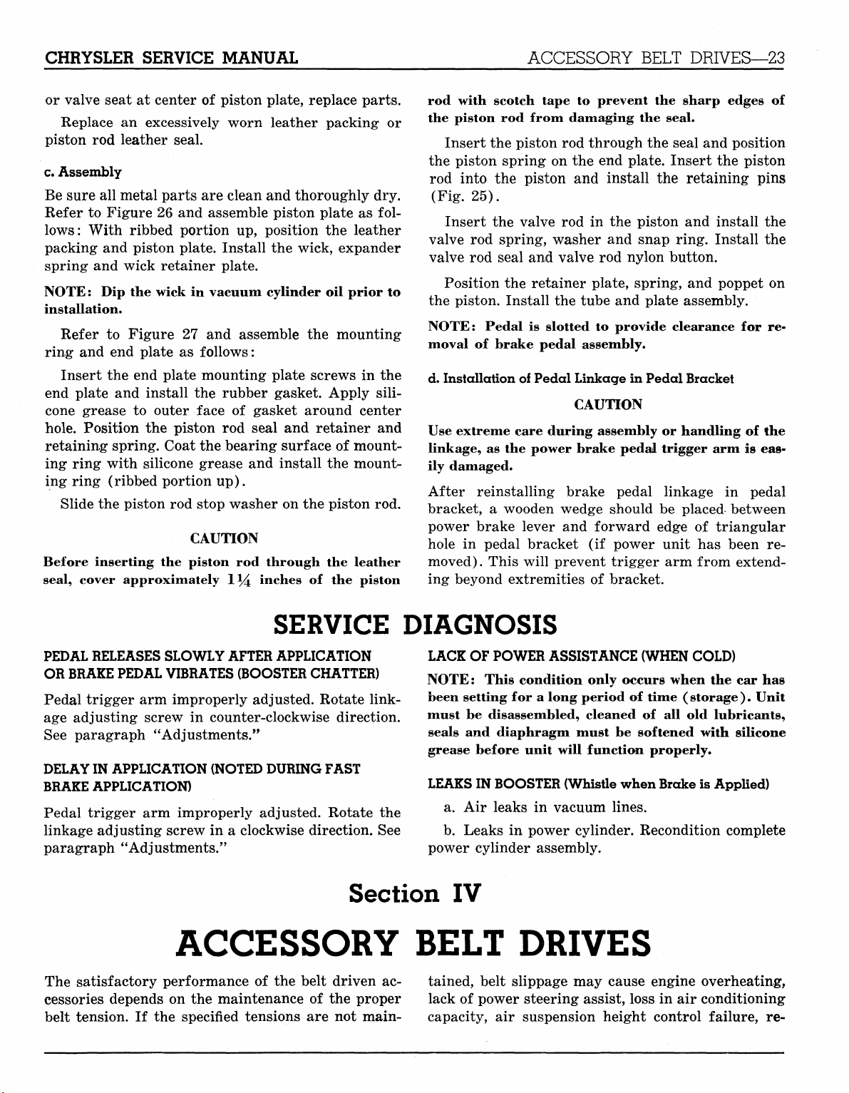
or valve seat at center of piston plate, replace parts.
Replace an excessively worn leather packing or
piston rod leather seal.
c.
Assembly
Be sure all metal parts are clean and thoroughly dry.
Refer to Figure 26 and assemble piston plate as follows:
With ribbed portion up, position the leather
packing and piston plate. Install the wick, expander
spring and wick retainer plate.
NOTE: Dip the wick in vacuum cylinder oil prior to
installation.
Refer to Figure 27 and assemble the mounting
ring and end plate as follows:
Insert the end plate mounting plate screws in the
end plate and install the rubber gasket. Apply sili-
cone grease to outer face of gasket around center
hole.
Position the piston rod seal and retainer and
retaining spring. Coat the bearing surface of mounting1 ring with silicone grease and install the mounting ring (ribbed portion up).
Slide the piston rod stop washer on the piston rod.
CAUTION
Before inserting the piston rod through the leather
seal, cover approximately 1*4 inches of the piston
rod with scotch tape to prevent the sharp edges of
the piston rod from damaging the seal.
Insert the piston rod through the seal and position
the piston spring on the end plate. Insert the piston
rod into the piston and install the retaining pins
(Fig. 25).
Insert the valve rod in the piston and install the
valve rod spring, washer and snap ring. Install the
valve rod seal and valve rod nylon button.
Position the retainer plate, spring, and poppet on
the piston. Install the tube and plate assembly.
NOTE: Pedal is slotted to provide clearance for re-
moval of brake pedal assembly.
d. Installation of Pedal Linkage in Pedal Bracket
CAUTION
Use extreme care during assembly or handling of the
linkage, as the power brake pedal trigger arm is easily damaged.
After reinstalling brake pedal linkage in pedal
bracket, a wooden wedge should be placed between
power brake lever and forward edge of triangular
hole in pedal bracket (if power unit has been removed). This will prevent trigger arm from extending beyond extremities of bracket.
SERVICE DIAGNOSIS
PEDAL RELEASES SLOWLY AFTER APPLICATION
OR BRAKE PEDAL VIBRATES (BOOSTER CHATTER)
Pedal trigger arm improperly adjusted. Rotate linkage adjusting screw in counter-clockwise direction.
See paragraph "Adjustments."
DELAY IN
BRAKE APPLICATION)
Pedal trigger arm improperly adjusted. Rotate the
linkage adjusting screw in a clockwise direction. See
paragraph ''Adjustments."
APPLICATION (NOTED DURING FAST
Section
ACCESSORY BELT DRIVES
The satisfactory performance of the belt driven accessories depends on the maintenance of the proper
belt tension. If the specified tensions are not main-
LACK OF POWER ASSISTANCE (WHEN COLD)
NOTE: This condition only occurs when the car has
been setting for a long period of time ( storage
must be disassembled, cleaned of all old lubricants,
seals and diaphragm must be softened with silicone
grease before unit will function properly.
LEAKS IN
a. Air leaks in vacuum lines.
b.
power cylinder assembly.
BOOSTER (Whistle when Brake is Applied)
Leaks in power cylinder. Recondition complete
).
Unit
IV
tained, belt slippage may cause engine overheating,
lack of power steering assist, loss in air conditioning
capacity, air suspension height control failure, re-
MyMopar.com
Page 26
CHRYSLER SERVICE MANUAL
ACCESSORY BELT DRIVES—23
or valve seat at center of piston plate, replace parts.
Replace an excessively worn leather packing or
piston rod leather seal.
c.
Assembly
Be sure all metal parts are clean and thoroughly dry.
Refer to Figure 26 and assemble piston plate as follows:
With ribbed portion up, position the leather
packing and piston plate. Install the wick, expander
spring and wick retainer plate.
NOTE: Dip the wick in vacuum cylinder oil prior to
installation.
Refer to Figure 27 and assemble the mounting
ring and end plate as follows:
Insert the end plate mounting plate screws in the
end plate and install the rubber gasket. Apply sili-
cone grease to outer face of gasket around center
hole.
Position the piston rod seal and retainer and
retaining spring. Coat the bearing surface of mounting1 ring with silicone grease and install the mounting ring (ribbed portion up).
Slide the piston rod stop washer on the piston rod.
CAUTION
Before inserting the piston rod through the leather
seal, cover approximately 1*4 inches of the piston
rod with scotch tape to prevent the sharp edges of
the piston rod from damaging the seal.
Insert the piston rod through the seal and position
the piston spring on the end plate. Insert the piston
rod into the piston and install the retaining pins
(Fig. 25).
Insert the valve rod in the piston and install the
valve rod spring, washer and snap ring. Install the
valve rod seal and valve rod nylon button.
Position the retainer plate, spring, and poppet on
the piston. Install the tube and plate assembly.
NOTE: Pedal is slotted to provide clearance for removal of brake pedal assembly.
d. Installation of Pedal Linkage in Pedal Bracket
CAUTION
Use extreme care during assembly or handling of the
linkage, as the power brake pedal trigger arm is eas-
ily damaged.
After reinstalling brake pedal linkage in pedal
bracket, a wooden wedge should be placed between
power brake lever and forward edge of triangular
hole in pedal bracket (if power unit has been removed). This will prevent trigger arm from extending beyond extremities of bracket.
SERVICE DIAGNOSIS
PEDAL RELEASES SLOWLY AFTER APPLICATION
OR BRAKE PEDAL VIBRATES (BOOSTER CHATTER)
Pedal trigger arm improperly adjusted. Rotate linkage adjusting screw in counter-clockwise direction.
See paragraph "Adjustments."
DELAY IN
BRAKE APPLICATION)
Pedal trigger arm improperly adjusted. Rotate the
linkage adjusting screw in a clockwise direction. See
paragraph ''Adjustments."
APPLICATION (NOTED DURING FAST
Section
ACCESSORY BELT DRIVES
The satisfactory performance of the belt driven accessories depends on the maintenance of the proper
belt tension. If the specified tensions are not main-
LACK OF POWER ASSISTANCE (WHEN COLD)
NOTE: This condition only occurs when the car has
been setting for a long period of time ( storage
must be disassembled, cleaned of all old lubricants,
seals and diaphragm must be softened with silicone
grease before unit will function properly.
LEAKS IN
a. Air leaks in vacuum lines.
b.
power cylinder assembly.
BOOSTER (Whistle when Brake is Applied)
Leaks in power cylinder. Recondition complete
).
Unit
IV
tained, belt slippage may cause engine overheating,
lack of power steering assist, loss in air conditioning
capacity, air suspension height control failure, re-
MyMopar.com
Page 27
24—ACCESSORY BELT DRIVES
CHRYSLER SERVICE MANUAL
duced generator charging rates, and greatly reduced
belt life. To avoid any such adverse effects, the following service procedure should be followed:
1.
Adjust all belts "in use"* to the specified belt
tension at new car preparation.
2.
Readjust all belts at the 2,000 mile inspection
and service.
3.
Check all belts by the deflection method at serv-
icing and readjust if needed,
4.
The new belt tension specifications should be
used on all new belt installations and the above procedure followed thereafter.
There are two methods by which belt tensions can
be properly established:
Torque Method — All generator and power steering
pump belts can be tightened to the specified tension
(see Tension Specifications that follow), by use of a
torque wrench. The generator belts are tensioned by
using a special tool C-3379, and torque wrench. The
power steering belts are tightened by inserting the
torque wrench in the square hole provided in the
bracket. Other belts can also be tightened by this
method if the adjusting bracket has a square hole.
To tighten belts by the torque method, loosen all
mounting bolts and apply the specified torque to the
accessory or idler. Tighten all mounting bolts while
the torque is applied to the accessory. If it is not possible to use the torque wrench because of clearance,
use an extension.
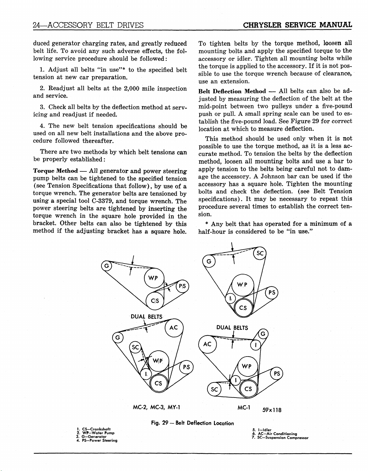
Belt Deflection Method — All belts can also be adjusted by measuring the deflection of the belt at the
mid-point between two pulleys under a five-pound
push or pull. A small spring scale can be used to establish the
five-pound
load. See Figure 29 for correct
location at which to measure deflection.
This method should be used only when it is not
possible to use the torque method, as it is a less accurate method. To tension the belts by the deflection
method, loosen all mounting bolts and use a bar to
apply tension to the belts being careful not to damage the accessory. A Johnson bar can be used if the
accessory has a square hole. Tighten the mounting
bolts and check the deflection, (see Belt Tension
specifications). It may be necessary to repeat this
procedure several times to establish the correct tension.
* Any belt that has operated for a minimum of a
half-hour is considered to be "in use."
1.
CS-Crankshaft
2.
WP-Water Pump
3. G—Generator
4. PS—Power Steering
MC-2,
MC-3, MY-1 MC-1
Fig.
29 — Belt Deflection Location
59xll8
5.
I—Idler
6. AC-Air Conditioning
7. SC—Suspension Compressor
MyMopar.com
Page 28
CHRYSLER SERVICE MANUAL
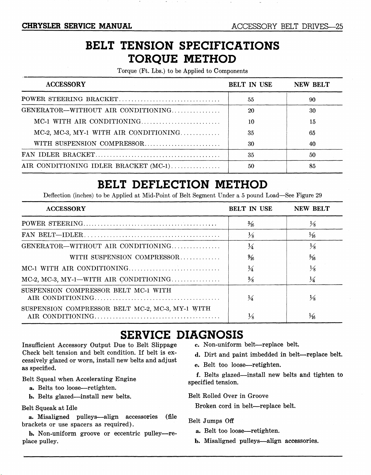
BELT TENSION SPECIFICATIONS
Torque (Ft. Lbs.) to be Applied to Components
ACCESSORY BELT DRIVES—25
TORQUE METHOD
ACCESSORY
POWER STEERING BRACKET
GENERATOR—WITHOUT AIR CONDITIONING
MC-1 WITH AIR CONDITIONING
MC-2,
MC-3, MY-1 WITH AIR CONDITIONING
WITH SUSPENSION COMPRESSOR
FAN IDLER BRACKET
AIR CONDITIONING IDLER BRACKET (MC-1)
BELT DEFLECTION METHOD
Deflection (inches) to be Applied at Mid-Point of Belt Segment Under a 5 pound Load—See Figure 29
ACCESSORY
POWER STEERING
FAN BELT—IDLER
GENERATOR—WITHOUT AIR CONDITIONING
WITH SUSPENSION COMPRESSOR
MC-1 WITH AIR CONDITIONING
MC-2,
MC-3, MY-1—WITH AIR CONDITIONING
SUSPENSION COMPRESSOR BELT MC-1 WITH
AIR CONDITIONING
SUSPENSION COMPRESSOR BELT MC-2, MC-3, MY-1 WITH
AIR CONDITIONING
BELT IN USE
55
20
10
35
30
35
50
NEW BELT
90
30
15
65
40
50
85
BELT IN USE NEW BELT
%,
Vs
VA
%>
Vs
Vs
Vs
Hi
Vs
%
Vs
M
Vs
Hi
SERVICE DIAGNOSIS
Insufficient Accessory Output Due to Belt Slippage
Check belt tension and belt condition. If belt is excessively glazed or worn, install new belts and adjust
as specified.
Belt Squeal when Accelerating Engine
a. Belts too loose—retighten.
b.
Belts glazed—install new belts.
Belt Squeak at Idle
a. Misaligned pulleys—align accessories
brackets or use spacers as required).
b.
Non-uniform groove or eccentric pulley—re-
place pulley.
(file
c. Non-uniform belt—replace belt.
d. Dirt and paint imbedded in belt—replace belt.
e. Belt too loose—retighten.
f. Belts glazed—install new belts and tighten to
specified tension.
Belt Rolled Over in Groove
Broken cord in belt—replace belt.
Belt Jumps Off
a. Belt too loose—retighten.
b.
Misaligned pulleys—align accessories.
MyMopar.com
Page 29
26—COOLING SYSTEM
CHRYSLER SERVICE MANUAL
Section V
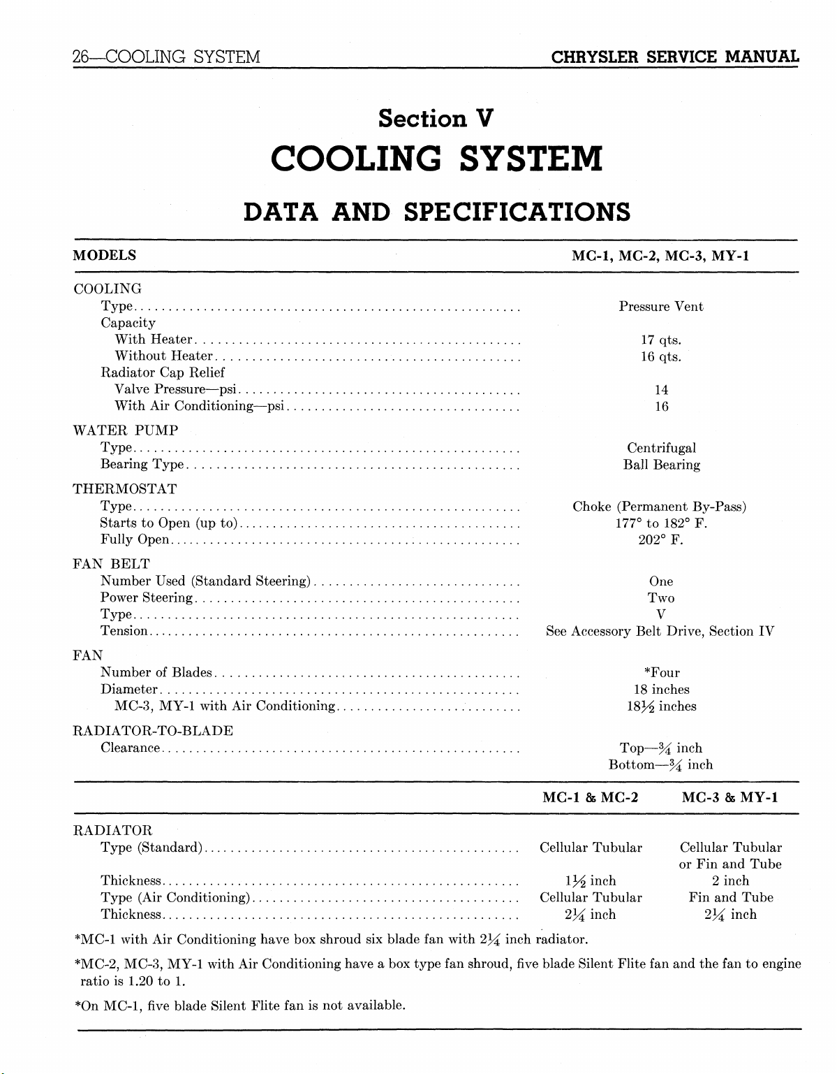
COOLING SYSTEM
DATA AND SPECIFICATIONS
MODELS MC-1, MC-2, MC-3, MY-1
COOLING
Type Pressure Vent
Capacity
With Heater 17 qts.
Without Heater 16 qts.
Radiator Cap Relief
Valve Pressure—psi 14
With Air Conditioning—psi 16
WATER PUMP
Type Centrifugal
Bearing Type Ball Bearing
THERMOSTAT
Type Choke (Permanent By-Pass)
Starts to Open (up to) 177° to 182° F.
Fully Open 202° F.
FAN BELT
Number Used (Standard Steering) One
Power Steering Two
Type V
Tension See Accessory Belt Drive, Section IV
FAN
Number of Blades , *Four
Diameter 18 inches
MC-3,
MY-1 with Air Conditioning 18J^ inches
RADIATOR-TO-BLADE
Clearance Top—% inch
Bottom—% inch
MC-1 & MG-2 MC-3 & MY-1
RADIATOR
Type (Standard) Cellular Tubular Cellular Tubular
or Fin and Tube
Thickness 1J/2 inch 2 inch
Type (Air Conditioning) Cellular Tubular Fin and Tube
Thickness 2^ inch 2lA inch
*MC-1 with Air Conditioning have box shroud six blade fan with 234 inch radiator.
*MC-2,
*On MC-1, five blade Silent Flite fan is not available.
MC-3, MY-1 with Air Conditioning have a box type fan shroud, five blade Silent Flite fan and the fan to engine
ratio is 1.20 to 1.
MyMopar.com
Page 30
CHRYSLER SERVICE MANUAL
ELECTRICAL SYSTEM—27
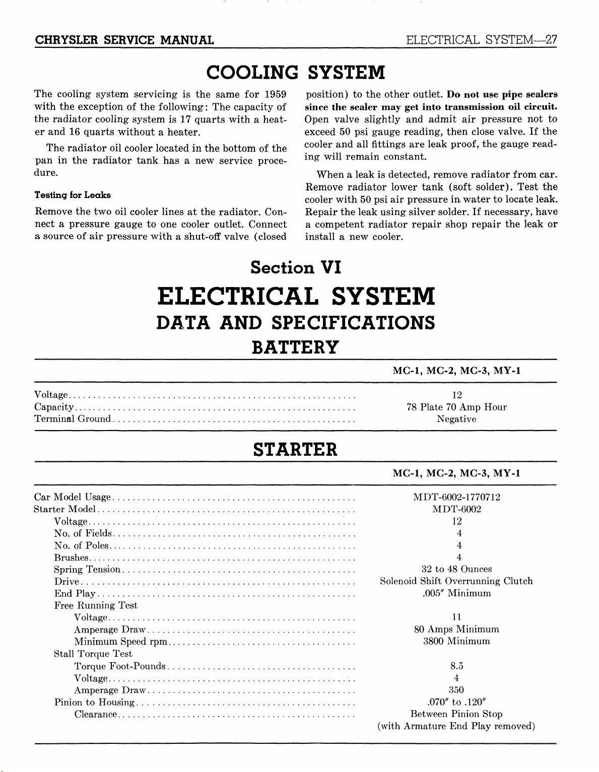
COOLING SYSTEM
The cooling system servicing is the same for 1959
with the exception of the following: The capacity of
the radiator cooling system is 17 quarts with a heater and 16 quarts without a heater.
The radiator oil cooler located in the bottom of the
pan in the radiator tank has a new service proce-
dure.
Testing for Leaks
Remove the two oil cooler lines at the radiator. Con-
nect a pressure gauge to one cooler outlet. Connect
a source of air pressure with a shut-off valve (closed
Section VI
ELECTRICAL SYSTEM
DATA AND SPECIFICATIONS
BATTERY
position) to the other outlet. Do not use pipe sealers
since the sealer may get into transmission oil circuit.
Open valve slightly and admit air pressure not to
exceed 50 psi gauge reading, then close valve. If the
cooler and all fittings are leak
ing will remain constant.
When a leak is detected, remove radiator from car.
Remove radiator lower tank (soft solder). Test the
cooler with 50 psi air pressure in water to locate leak.
Repair the leak using silver solder. If necessary, have
a competent radiator repair shop repair the leak or
install a new cooler.
MG-1,
proof,
MG-2, MG-3, MY-1
the gauge read-
Voltage
Capacity
Terminal Ground
78 Plate 70 Amp Hour
12
Negative
STARTER
MC-1,
MC-2, MC-3, MY-1
Car Model Usage MDT-6002-1770712
Starter Model „ MDT-6002
Voltage 12
No.
of Fields 4
No.
of Poles 4
Brushes 4
Spring Tension 32 to 48 Ounces
Drive Solenoid Shift Overrunning Clutch
End Play .005" Minimum
Free Running Test
Voltage 11
Amperage Draw 80 Amps Minimum
Minimum Speed rpm 3800 Minimum
Stall Torque Test
Torque Foot-Pounds 8.5
Voltage 4
Amperage Draw 350
Pinion to Housing .070" to .120"
Clearance Between Pinion Stop
(with Armature End Play removed)
MyMopar.com
Page 31

CHRYSLER SERVICE MANUAL
ELECTRICAL SYSTEM—27
COOLING SYSTEM
The cooling system servicing is the same for 1959
with the exception of the following: The capacity of
the radiator cooling system is 17 quarts with a heater and 16 quarts without a heater.
The radiator oil cooler located in the bottom of the
pan in the radiator tank has a new service proce-
dure.
Testing for Leaks
Remove the two oil cooler lines at the radiator. Con-
nect a pressure gauge to one cooler outlet. Connect
a source of air pressure with a shut-off valve (closed
Section VI
ELECTRICAL SYSTEM
DATA AND SPECIFICATIONS
BATTERY
position) to the other outlet. Do not use pipe sealers
since the sealer may get into transmission oil circuit.
Open valve slightly and admit air pressure not to
exceed 50 psi gauge reading, then close valve. If the
cooler and all fittings are leak
ing will remain constant.
When a leak is detected, remove radiator from car.
Remove radiator lower tank (soft solder). Test the
cooler with 50 psi air pressure in water to locate leak.
Repair the leak using silver solder. If necessary, have
a competent radiator repair shop repair the leak or
install a new cooler.
MG-1,
proof,
MG-2, MG-3, MY-1
the gauge read-
Voltage
Capacity
Terminal Ground
78 Plate 70 Amp Hour
12
Negative
STARTER
MC-1,
MC-2, MC-3, MY-1
Car Model Usage MDT-6002-1770712
Starter Model „ MDT-6002
Voltage 12
No.
of Fields 4
No.
of Poles 4
Brushes 4
Spring Tension 32 to 48 Ounces
Drive Solenoid Shift Overrunning Clutch
End Play .005" Minimum
Free Running Test
Voltage 11
Amperage Draw 80 Amps Minimum
Minimum Speed rpm 3800 Minimum
Stall Torque Test
Torque Foot-Pounds 8.5
Voltage 4
Amperage Draw 350
Pinion to Housing .070" to .120"
Clearance Between Pinion Stop
(with Armature End Play removed)
MyMopar.com
Page 32

28—ELECTRICAL SYSTEM
Solenoid Switch
Pull-in Coil
Hold-in Coil
CHRYSLER SERVICE MANUAL
STARTER (Cont'd)
28.6 to 32.9 Amps at 6 Volts
10.2 to 11.8 Amps at 6 Volts
LIGHT BULBS
Number Mazda
Required Number
Headlights Inner (High Beam Only) 2
Headlights Outer (High and Low Beam) 2
Headlight Beam Indicator Light 1
Parking and Front Turn Signal 2
Rear Tail, Stop and Turn Signal Light 2
License Plate Light 2
Glove Box Light 1
Instrument Lights 4
Map Light 1
Turn Signal Indicator Light 2
Dome Light 1 or 2
Hand Brake Warning Light 1
Back Up Light 2
Transmission Push Button Light 1
Radio Dial Light 2
Clock Light 1
Trunk Light 1
CIRCUIT PROTECTORS
4001
4002
57
1034
1034
67
57
57
1004
57
1004
90
1073
57
1891
57
1003
C.P. or Chrysler
Watts Part No.
37J^ W
50-37^ W
2
32-4
32-4
3
2
2
15
2
15
6
32
2
2
15
1753435
1753436
127934
151567
151567
142450
127934
127934
151578
127934
151578
142453
142456
127934
127934
151577
Circuit
Type
Rated Capacity
Location
Lighting System Circuit Breaker 22J^ Ampere Integral with Headlight Switch
Clock Fuse 1 Ampere At Fuse Block*
Windshield Wiper Circuit Breaker 6 Ampere At Fuse Block*
Radio Fuse 7*^ Ampere At Fuse Block*
Dome Lamp Fuse 6 Ampere At Fuse Block*
Window Lifts Circuit Breaker 20 Amp-30 Amp At Terminal Block
Behind Left Front Kick Panel
Back-Up Light Fuse 6 Ampere At Fuse Block*
Cigar Lighter Fuse 14 Ampere At Fuse Block*
Six-Way Seat Circuit Breaker 40 Ampere At Terminal Block
Behind Left Front Kick Panel
Rear Defroster Fuse 6 Ampere At Fuse Block*
Heater Circuit Breaker 20 Ampere At Fuse Block*
Air Conditioner (front) Circuit Breaker 30 Ampere At Fuse Block*
Air Conditioner (rear) Circuit Breaker 20 Ampere At Fuse Block*
Air Conditioner (dual) Circuit Breaker 30 Ampere At Fuse Block*
*Fuse block is located at instrument panel (driver's compartment) to the left of radio.
MyMopar.com
Page 33

Gar Model
Generator Model
Standard
With Air Conditioning
Front Unit Only
Dual Air Conditioning
Front and Rear
MC-1
GJM-8001A;
GJM-8001A;
GHM-8005B;
GENERATORS
1842801
1842801
1889400
GJM-8001A; 1842801
GJM-8002A; 1842797
GHM-8001A; 1842774
MC-2,
MC-3
MY-1
GHM-8005A; 1842778
GHM-8001A; 1842774
GHM-8001A; 1842774
Gas Heater
Heavy Duty
Heavy Duty True-Level Torsion Aire..
Generator Model
Rotation
Voltage
Rated Output
Control
Ground Polarity
Poles '..
Brushes
Brush Spring Tension
Bearings
End Play
Field Coil Draw (Arm. to field term.)
GGA-6003E;
GGA-6001N
GGA-6003E
Clockwise at
Drive End
12
40 Amperes
Vibrating Regulator
Negative
2
2
34 to 41 ounces
Ball—Both Ends
.003"-.010"
1.2 to 1.3 Amps
at 10 Volts
1842603
GHM-8001A
Clockwise at
Drive End
12
30 Amperes
Vibrating Regulator
Negative
2
2
35 to 53 ounces
Ball—Both Ends
.003"-.010"
1.2 to 1.3 Amps
at 10 Volts
GHM-8005A; 1842778
GGA-6003E; 1842603
GGA-6001N; 1658863
GHM-8005A
GHM-8006B
Clockwise at
Drive End
12
30 Amperes
Vibrating Regulator
Negative
2
2
35 to 53 ounces
Ball & Sleeve
.003"-.010"
1.2 to 1.3 Amps
at 10 Volts
GHM-8005A; 1842778
GGA-6003E; 1842603
GGA-6001N; 1658863
GJM-8001A
Clockwise at
Drive End
12
35 Amperes
Vibrating Regulator
Negative
2
2
18 to 36 ounces
Ball & Sleeve
.003'/-.010'
/
1.4 to 1.7 Amps
at 10 Volts
GJM-8002A
Clockwise at
Drive End
12
35 Amperes
Vibrating Regulator
Negative
2
2
18 to 36 ounces
Ball—Both Ends
.003"-.010"
1.6 to 1.7 Amps
at 10 Volts
Motoring Draw
2.9 to 3.4 Amps
at 10 Volts
Output Tests (at 70° F.) 10 Amps, 13.4 Volts
at 1020 max. rpm
40 Amps, 15 Volts
at 1800 max. rpm
3.3 to 3.8 Amps
at 10 Volts
10 Amps, 13.5 Volts
at 1040 max. rpm
30 Amps, 15 Volts
at 1800 max. rpm
3.3 to 3.8 Amps
at 10 Volts
10 Amps, 13.5 Volts
at 1040 max. rpm
30 Amps, 15 Volts
at 1800 max. rpm
3.8 to 4.3 Amps
at 10 Volts
10 Amps, 13.4 Volts
at 1480 max. rpm
35 Amps, 15 Volts
at 2400 max. rpm
3.8 to 4.3 Amps
at 10 Volts
10 Amps, 13.4 Volts
at 1480 max. rpm
35 Amps, 15 Volts
at 2400 max. rpm
MyMopar.com
Page 34

30—ELECTRICAL SYSTEM CHRYSLER SERVICE MANUAL
REGULATOR
MC-1,
Car Model
MC-2, MC-3, MY-1
Regulator Model VRX-6301A-1842798
(For 35 Amp Generators)
Volts
Ground Polarity
12
Negative
VRX-6201A-1642333
(For 30 Amp Generators)
12
Negative
VAT-6201-1662137
(For 40
Amp Generators)
12
Negative
Resistors
Marked 60..
Marked 38..
Marked 30..
34.5 to 45 ohms
55.0 to
34.5 to
28.0 to
70.0
42.0
34.5
ohms
ohms
ohms
Voltage Regulator
Voltage Winding Resistance.
Armature Air Gap
44.0 to 49.0 ohms
.048 to .052 inch
Contacts closed with high limit gauge installed.
Contacts open with low limit gauge installed.
Gauge on contact side and next to brass stop pin.
Voltage Setting (operating voltage)
After 15 minutes run at 7 amperes
Temperature in degrees F 50°
Maximum Setting 15.04
Minimum Setting 14.42
60°
14.97
14.36
70°
14.90
14.30
80°
14.83
14.23
90°
14.76
14.16
100°
14.69
14.09
110°
14.01
14.62
120°
14.54
13.94
Current Limiting Regulator
Armature Air Gap
.048 to .052 inch
Contacts closed with high limit gauge installed.
Contacts open with low limit gauge installed.
Gauge on contact side and next to brass stop pin.
Current Setting (After voltage Regulator Setting)
Operating Amperage after 15 minutes at 7 amperes. Then followed with a 15 minute run at rated current regulator
setting below 13.5 volts).
Temperature (F)....
Model VRX-6201A (1642333) 30 Amp. Max. Setting. .. .
Min. Setting
Model VRX-6301A (1842798) 35 Amp. Max. Setting. . . .
Min. Setting....
Model VAT-6201 (1662137) 40 Amp. Max. Setting....
Min. Setting....
50°
35
31
39
35
46
42
60
33
29
38
34
45
41
c
70°
32
28
37
33
44
40
80°
31
27
36
32
43
39
90°
30
26
35
31
42
38
100°
29
25
34
30
41
37
Cut-Out Relay:
Voltage Winding Resistance
Air Gap (contacts open)
107 to
.031 to
121 ohms
.034 inch
(Measure gap as near to hinge as possible)
Point Gap (Minimum)
Contacts Close (Volts)
Contacts Open (after charge of 10 amperes)
Discharge Amperes
.015 inch
12.6 to
0
to 6 amperes (discharge)
8.2 to
13.6 Volts
9.3 Volts
MyMopar.com
Page 35

CHRYSLER SERVICE MANUAL
Car Model
DISTRIBUTOR
MC-1,
MG-2
ELECTRICAL SYSTEM—31
MC-3,
MY-1
Distributor Model....
Contact Gap
Dwell
Condenser Capacity
Breaker Arm Tension
Drive
Side Play (shaft)
End Play (after assembly)
Firing Order
Rotation
Timing
Automatic Advance
Distributor Degrees and rpm.
Vacuum Advance
Distributor Degrees and Inches of Vacuum
IBP-4006-1842804
.015 to .018 inch
27° to 32°
.25 to .285 Microfarad
17 to 20 ounces
Camshaft
.005 inch Max.
.003 to .010 inch
18436572
Counter-clockwise
10° BTC
0°@ 270 to 540
0° to2°@ 540
2° to4°@ 800
4° to6°@ 1500
6.5° to
8.5° @ 2350
0° to 7.2 to 9.1"
4.5° to
7.5° @ 12"
9.5° to
12.5° @
16.5"
IBS-4010A-1842805
.015 to .018 inch
(one set points 27° to 32°)
(both sets points 34° to 40°)
.25 to .285 Microfarad
17 to 20 ounces
Camshaft
.005 inch Max.
.003 to .010 inch
18436572
Counter-clockwise
10° BTC
0°@310to490
0° to
2° @
490
3.5° to 5.5° @ 800
6°to8°@ 1550
8.5° to
10.5° @
0°@7.5to9.1"
6.0° to
11.5° to 14.5°© 18.2"
9° @
2300
13"
CAR MODEL
Spark Plugs
Type
Size
Gap...
SPARK PLUGS AND COIL
MC-1,
MC-2
A-42
14 mm
.035 inch
HIGH TENSION CABLES WITH BUILT-IN RESISTANCE
No.
1 Cable 8,300 to 16,600 Ohms
No.
2 Cable 5,500 to 11,000 Ohms
No.
3 Cable 8,100 to 16,200 Ohms
No.
4 Cable 6,000 to 12,000 Ohms
No.
5 Cable 8,800 to 17,600 Ohms
No.
6 Cable 6,300 to 12,600 Ohms
No.
7 Cable 9,400 to 18,800 Ohms
No.
8 Cable 7,200 to 14,400 Ohms
MC-3,
A-42
14 mm
.035 inch
MY-1
MyMopar.com
Page 36

32—ELECTRICAL SYSTEM CHRYSLER SERVICE MANUAL
SPARK PLUGS
CAR MODEL MC-1, MC-2, MC-3, MY-1
Coil
Model CAH-4001
Ballast Resistor PU-5001
Amperes
Engine Stopped 3.1 Amperes
Engine Idling 2.5 Amperes
AND
COIL (Cont'd)
HORNS
All Models
Make Auto-Lite, Spartan
Current draw at 12.4 volts 9 to 10 amps
ELECTRIC WINDSHIELD WIPER
All Models
Variable Speed Motor
Rated Volts. 12
Resistor (ohms) (Variable speed wiper) 17-40
Field Current Draw at 13.5 volts . 13^ to 2 amps
Motor Current Draw (with dry glass)
High Speed
Low Speed 3 amps at 35 to 40 rpm
1
j/£
amps at 66 to 75 rpm
POWER SEAT LIFTS
All Models
Type Motor Series Wound
Rated Voltage 12
Current Draw with Passenger Load Pounds Amps Volts
Vertical Lift 500 50-60 10.5
200 40-45 10.6
Horizontal Lift 600 60 10.4
150 35 11.0
WINDOW LIFTS
All Models
Type Motor Series Wound
Rated Voltage 12
Maximum Stall Current 25 amps at 8.9 volts
MyMopar.com
Page 37

CHRYSLER SERVICE MANUAL
ELECTRICAL SYSTEM
Servicing the electrical system for the 1959 Chrysler
and Imperial Models is the same as for the 1958
models with the following added information.
SPEEDOMETER REMOVAL
Chrysler—Disconnect battery. Disconnect speedom-
eter cable housing. Remove the two nuts and washers
from the rear of the speedometer. Slide speedometer
out the rear of panel.
Imperial—Disconnect battery. Disconnect speedom-
eter cable housing. Remove 7 screws from the rear
of speedometer and pull out speedometer from rear
of panel.
SIX-WAY ELECTRIC POWER SEAT — OPTIONAL
The six-way electric power seat is driven by a two-
way electric motor which operates through a solenoid and clutch assembly that supplies power through
ELECTRICAL SYSTEM—33
flexible cables to slave units located in the seat tracks.
The control switch is located on the left side of the
front seat and is wired through relay to a 40 amp
circuit breaker which is located behind the left front
kick panel.
CONTROL CIRCUITS
Power is supplied to the motor relay from the circuit
breaker. Three wires go to the switch from the motor relay.
One wire (red) is used for power and two wires
(white and blue) are used for directional control of
the motor.
Three additional wires go from the switch (yellow,
green and brown) to the solenoid and clutch assembly which control movement of front, rear and horizontal risers. (See chart below.)
For Forward Horizontal
For Forward Tilt
[Red
Connect Wires<j White
[Green
For Rearward Horizontal
fRed
Connect Wires^j Blue
Green
REMOVAL
CABLES — POWER SEAT
Refer to the Chrysler Service Manual D-16350 for
removing and installing the power seat flexible cables.
Seat guides should be in the up and forward position
when installing cables. Make sure guides are at the
same position (in alignment).
REMOVAL AND INSTALLATION OF MOTOR —
POWER SEATS
Removal—Disconnect the motor wires at relay. Re-
move the two nuts holding the motor to the drive
unit. Remove the motor from drive unit and rubber
coupling.
AND
INSTALLATION OF FLEXIBLE
CAUTION:
Connect
For Rearward Tilt
Connect Wires^j White
For Straight Up
[Red
Wires*)
White
[Yellow
fRed
[Brown
Installation—Install rubber coupling on motor shaft.
Align rubber coupling with the slot on the slave unit
shaft. Install motor and reconnect wires to relay.
DRIVE UNIT AND SOLENOID ASSEMBLY
POWER SEATS
Disassembly—Remove the drive unit from the seat
assembly. Remove the two screws holding plate and
solenoids to the drive unit. Remove the plate and so-
lenoid assembly. Be careful not to lose the three
springs under the solenoid when removing the sole-
noid coils. Bend back the tabs of the solenoid cover.
Unsolder the coil ground wire at the cover tab. Remove the cover from the coil. Remove the screws
holding the cover on the drive unit. Remove the
cover and lift out the clutch lever and shaft.
Assembly—Install the clutch lever and shaft. Make
sure the lever is properly seated on the drive collar.
Connect Wires J White
For Straight Down
Connect Wires j Blue
fRed
I Yellow
[Brown
[Red
I
Yellow
[Brown
—
MyMopar.com
Page 38

RT. PARK & T/SIG. LAMP
RT. AUTO. DOOR I
| 9* CA
18
RADIO
LAMP
YELLOW-4 p*<*
GLOVE BOX SW.
181 YELLOW
r
.RT. MAP LP.
-CIGAR LIGHTER
FUSE BLOCK
RT.
DUAL HEADLAMP
SP.
EQ. HORN
t=Q
HORNS
16 DK. GREEN
LT.
DUAL HEADLAMPS
LT.
PARK & T/SIG. LAMP
IGNITION DISTRIBUTOR
RADIO CONDENSER
TEMP.
GAUGE
SENDING
UNIT
18 VIOLET
GENERATOR
HORN RELAY
"18 TAN"
-16 BLACK
18 LT. GREEN"
BATTERY
GENERATOR REGULATOR/GRD.
0«
12 RED
16 BROWN-
-16 RED-
18 YELLOW
18 DK. GREEN
STARTEI
RELAY
GRD.
NEUTRAL SAFETY SWITCH
WIPER
IGNITION
COIL RESISTOR
LAMP^
ITCH-
NOTE: 18-BLACK CIRCUIT
WITHOUT POWER STEERING
STARTER MOTOR &
STARTER SOLENOID
SER
12 BROWI
tfpPIp
—18 BLACK-
18 DK. BLUE
VIOIET_10 RED
t—12 BLACK
BATT.
ARM
MOTOR
COIL
LUE
18D
TO SEAT ADJ. SW.
¥*** SIGNAL LAMP SWITCH
TAN TO W/LIFT SW.
18 ORANGE
r-18 YELLOW-
BACK UP LP. SW.
LT. AUTO. DOOR SWITCH
PUSH
BUTTON
"GEAR
SHIFT LP.
OIL GAUGE
FUEL GAUGE
,RT. T/SIG. LP.
-2I T/SIG. SW.
LT. MAP LP.
HI BEAM IND. LP.
CLOCK LP.
HANDBRAKE IND. LAMP
LT. T/SIG. LP.
I—LJ
18 LT. BLUE
-18 BLACK-^
14 LT. GREEN-
18 WHITE-
DISCONNECT
TO HORN
BUTTON
REAR WINDOW
DEFROSTER SW.
REAR OF FRONT SEAT
CIGAR LIGHTER MC3
4 DR. SEDAN 4 DR. HT.
4 DR. SUB.
fT8 PINK
18 VifrlTE
•-C/LITER
-DOME
CLOCK
••RR. A/C
-RADIO
*B/UP LP
RR. DEFR
Fig. 30 — Chassis and Instrument Panel Wiring Diagram — Models MC-1, 2 and 3
59x58
MyMopar.com
Page 39

RT.
PARK & T/SIG. LAMP
TRIAD HORN
IGNITION DISTRIBUTOR
2 4 6 8
SPARK PLUGS
13 5 7,
RADIO CONDENSER
TEMPERATURE GAUGE
IGNITION COIL
COIL RESISTOR
TURN SIGNAL RELAY
16
BLUE
"YELLOW
TURN SIG.
..AUTO.
RT. DOOR
GLOVE BOX
LAMP MAP
SW
SW.
TURN
SIG.
AUTO.
SW.
SWIT
A/C & HTR.
RR. A/C
RADIO REAR WINDOW
INSTRUMENT PANEL
R
DEFROSTER MOTOR
REAR WINDOW
REAR SHELF PANEL
LT.
PARK &
r/SIG. LAMP
16 LT.
-IB—
ROWN SAFETY
ROWN-0*-
I NEUTRAL
12BLXCK SWITCH
., HAND BRAKE
AD
ARM
- LAMP FLASHER
BATT.
WINDOW LIFT,
RD
„'
SEAT ADJUSTER
ELD
CIGAR LIGHTER
MYI-L CLOTH TRIM 4
Fig. 31
—Chassis
FOOT DIMMER
1 REQ'D. 2 REQ'D
GREEN
SWITCH
CIRCUIT BREAKERS
LEATHER TRIM
14 LT. GR
and
Instrument
-18 BRO
HAND BRAKE SW.
•TO REAR SEAT
CIGAR LIGHTER
LT.
DOOR SW.
FO SEAT ADJ.
Panel
Wiring
BUTTON
R SHIFT LP.
MANUAL T/SIG.
CANCELING SW
Diagram — Model
LT.
f'/SIG. LP.
DO.
MY-1
LAMP
w/s
WASHER
SWITCH
6 RED
BLUE
6
BLACK
16
YELLOW
59x59
MyMopar.com
Page 40

36—ELECTRICAL SYSTEM
LOCK RELAY
BATTERY
C/LITER C/B 8 AMP.
S/ADJ. C/B 40 AMP
W/L C/B. 30 AMP.
12-LT. BLUE CIRCUIT GOES
TO W/LIFT
C/B ON 4 D'RS
& C/LT'R.
C/B ON 2 D'RS.
-14 YELLOW
RT. FRT.
SW. &
PINK
14 VIOLET
14 VIOLET-
PINK
GRAY-
14 WHITE-
16 ORANGE-pn—UNLOCK
12 LT. BLUE+M—FEED
16 PINK 1£*—LOCK
12 ORANGE
RT.
14 DK. BLUE p [_
LT.
FRT. DR.
BLACK-
•VIOLET-L-T
14
RT.
FRT.
DOOR LOCK
14
LT.
GREEN
FRT.
DOOR LOCK SOLENOID
LT.
FRT.
LT.
FRT.
DOOR LOCK
14 BROWN-|o f>T
MASTER
SW. & MTR.
ORANGE-
14 WHITE
SW
RT.
RR.
CIGAR LIGHTER
LT.
RR.
CIGAR LIGHTER
14
LT.
GREEN-
ORANGE
DOOR LOCK SOLENOID
SW.
CHRYSLER SERVICE MANUAL
^^---RT.
fff—
rtsJ
ff=] ORANGE
rty RED
J SW.
RR. SW. & MTR
GRAY-*
DK.
GREENL
\T. RR.
DR.
GRAY-foj
RT.
RR.
DOOR
LOCK SOLENOID
LT.
RR.
DOOR
LOCK SOLENOID
ORANGEF~~|
Fig.
32 — Window Lifts, Cigar Lighter and Electric Door Locks Wiring Diagram
Install the cover and screws. Install the coil in the
coil cover with the coil ground wire next to one of
the tabs. Position the cover tabs in the slots on the
coil plate. Bend over the tabs and solder the coil
ground wire to the tab and plate.
Install the three solenoid springs and position the
solenoids over the springs. Fasten the solenoids to
the drive unit. Install the drive unit.
REMOVAL AND INSTALLATION OF SLAVE UNIT —
POWER SEATS
Remove the drive unit and cables. With the seat
guide in the up and forward position, remove the
long clevis pin from the front of the guide.
Remove the front rack clevis pin. To facilitate the
POWER SEAT SERVICE DIAGNOSIS
ENTIRE UNIT INOPERATIVE
Remove all wires from seat switch and connect to-
gether as shown in the chart for the six various con-
trols operations, if the operation is normal, by
connecting wires. Replace switch.
MOTOR INOPERATIVE
removal of the slave unit, remove the slave unit cap.
Do not lose the springs under the cap. The springs
are between the racks and slave cap. Remove the
nuts holding the slave unit to the guide. Remove
unit.
Installation—Position the slave unit over the studs
on the guide base. Position the racks in the slave
unit so they will be in the up and forward position.
Fasten the racks to the guide assembly. Position the
springs on the rack and install slave unit cap. Install
the slave unit mounting nuts. Install the front guide
clevis pin. Install cables in slots and check the operation of power seats. Install drive unit and cables.
Figures 30, 31 and 32 show new wiring diagrams
for Chrysler and Imperial cars for 1959.
does not light, check for continuity in #10 red feed
wire,
faulty circuit breaker or poor connection between circuit breaker and starter relay. If test light
lights,
connect #10 red feed wire with red and black
or red and green wires from motor. If motor runs,
relay was faulty, replace relay. If motor does not
run, the motor is faulty, replace motor.
Check red wire at relay with test light. If test light
SEAT INOPERATIVE (MOTOR RUNS)
MyMopar.com
Page 41

CHRYSLER SERVICE MANUAL
ELECTRICAL SYSTEM—37
Jump wire from #10 feed wire to each solenoid
terminal on clutch assembly. Solenoids should each
"click" as jumper is connected. If solenoid does not
click:
(a) Check wire in harness for open circuit. Re-
pair.
(b) Possible seized solenoid armature in coil. Re-
place coil.
(c) Possible burned-out solenoid. Replace sole-
noid.
SEAT INOPERATIVE (MOTOR RUNS
SOLENOIDS CLICK)
Check drive unit for stripped or broken gear. Replace drive unit if necessary.
SLAVE UNIT INOPERATIVE
(MOTOR, SOLENOIDS & DRIVE UNIT O. K.)
Check for broken drive cable and replace as necessary.
SEAT HAS ROCKING MOTION
&
(e) Remove horizontal stops located on slide at
(D).
(f) Separate seat slide (C) from base (N) by
pressing slide rearward which will allow rollers (A)
to jump retaining rivets (E, F, G, H) thereby separating slide from base.
(g) Remove rivet (F) and replace with 5/16-18
x 1/2" cap screw (1) to retain proper position.
NOTE: A frayed drive cable may be repaired by
applying light coating of solder and then grinding to
cable size.
SEAT TRACK EXCESSIVELY LOOSE
Due to loose rivet joints.
(a) Disassemble upper track seat support (B) by
removing cotter keys and pins.
(b) Remove seat support and tighten all riveted
joints (J) by peening with a ball peen hammer.
LOOSE FRONT LEVERS
Excessive movement between slide and base of track
assembly. This condition is possible due to roller
being out of position.
(a) Remove power seat assembly from vehicle.
(b) Remove seat drive tubes from slave unit.
CAUTION:
Do not run motor with drive cables and tubes disassembled or unit will be placed out of synchroni-
zation.
(c) Remove seat support (B).
(d) Remove seat slave unit from seat track slide
(C).
RESISTANCE TYPE SPARK PLUG CABLES
All 1959 Chrysler and Imperial engines incorporate
conventional spark plugs (without resistors), along
with resistance type spark plug cables to eliminate
radio interference.
Arc weld front levers (K) to prevent movement between the two sections comprising the front lever assembly.
SEAT CHUCK FORE AND AFT
Due to loose horizontal rack support arm to lower
track base.
(a) Remove seat track assembly from vehicle and
arc weld.
(b) Tighten rack attaching pins (M) by arc weld-
ing.
(c) Check for loose horizontal rack in slave unit
gear train. If loose, replace slave unit.
the center of conventional spark plug cable. Full
contact is made between the core and terminals by
means of a short wire pin pushed into the ends of
the cable.
For identification purposes, this new cable has
"RADIO" printed on it.
The new cable uses a graphite or composition type
conducting core replacing the copper wire found in
Precautions must be observed in handling to prevent damage to the core. The cable should be removed from the spark plug by grasping the cable
cover and pulling straight off with a steady, even
MyMopar.com
Page 42

38—ELECTRIGAL SYSTEM
CHRYSLER SERVICE MANUAL
pull. Pulling sideways could jam the terminal on the
spark plug and cause the cable
to
separate from the
terminal. The cable terminal should not be crimped
to
the
point that excessive force
move
it
from the spark plug.
The cables should never
be
is
required
removed
by
to re-
giving
them a quick jerk. Doing so can stretch the core and
cause a high resistance or open circuit.
core
is
suspected, a resistance check with
meter should be made. The resistance
If a
damaged
an
of
the various
ohm-
plug cables will vary because of the different lengths,
see chart below:
SPARK PLUG CABLES WITH
BUILT-IN RESISTANCE
No. 1 Cable
No. 2 Cable 5,500
No. 3 Cable 8,100
No. 4 Cable 6,000
No. 5 Cable
No. 6 Cable 6,300
No. 7 Cable 9,400
No. 8 Cable 7,200
8,300
8,800
to
16,600 Ohms
to
11,000 Ohms
to
16,200 Ohms
to
12,000 Ohms
to
17,600 Ohms
to
12,600 Ohms
to
18,800 Ohms
to
14,400 Ohms
If any cable has appreciably more resistance than
specified, check
tact with the pin and the pins
the core.
stalled
specified,
If
and the
the
to
be sure the terminals are
is in
full contact with
in
the terminals and pins are properly
cable resistance
cable should
is
be
replaced with
still more than
a new
con-
in-
resistance type cable.
A new terminal should never
be
attached
to the
resistance core cables unless the wire pin is in place;
otherwise, contact will
core. This will result
core which will cause engine malfunctioning
not be
in
maintained with
arcing and burning
the
of the
and
radio interference.
CAUTION
Resistor type spark plugs
the
new
resistance type cable.
of
the
spark plugs
may
ignition system. When replacing a spark plug,
sure
to
use the
correct type specified
are
never
to be
used with
The
added resistance
cause malfunctioning
for
of
the
be
the par-
ticular engine.
SERVICE DIAGNOSIS
If the radio develops excessive noise
pronounced engine miss, check
for
or if
faulty
there
or
is a
broken
cables.
THE AUTOMATIC BEAM CHANGER
The automatic beam changer
light control unit which senses the headlight intensity from other vehicles
the headlights
ed,)
to
the upper
(of
or
the vehicle
lower beam position.
A scanner and base assembly (Fig. 33),
ed on top
of
the instrument panel, directly
of the steering column. The control unit Fig. 33
mounted on a convenient structural part (grounding
purposes)
of
the vehicle's body. (Figure 34).
OPERATION
The Automatic Beam Changer will change the headlight
to
the "lower beam" when
approached
at
a distance
The unit will reset the headlights to the "high beam"
position within 1/2 second after the approaching car
has passed.
The headlight beam setting can be interrupted by
using the conventional dimmer switch.
an "upper beam" setting and
is an
and
automatic head-
automatically adjusts
in
which
it is
mount-
is
in
an
oncoming car
of
approximately 1200 feet.
If
the unit has
the
driver feels that
mount-
front
is
is
A0JUSTIN8 KNOB
Fig.
33 — Scanner
—LOCKING-SCREW
SCANNER
CONTROL UNIT
and
Control Unit
MyMopar.com
Page 43

CHRYSLER SERVICE MANUAL
ELECTRICAL SYSTEM—39
"SCANNER"
INSTRUMENT
PANEL
Fig.
34 — Location
AIMING
of
Beam Changer Control Unit
THE
AUTOMATIC BEAM CHANGER
PRE-AIMING INSTRUCTIONS
Before attempting to aim the automatic beam changer, complete the following pre-aiming instructions.
Place vehicle on a level floor.
If the vehicle is placed in an area in which the
floor is not level, it will be necessary to take this
condition into consideration when "aiming" the
"scanner" unit. Refer to aiming the "scanner"
unit.
Check front spring height. Adjust to specifications
—if necessary.
Check tire inflation. Tire pressure should not vary
more than 3-5 pounds among tires.
Rock vehicle sideways to allow spring shackles,
et cetera to assume a normal position.
If gasoline tank is not full, place a 100 pound
weight in trunk of vehicle.
There should be no other load in the vehicle, other
than the driver.
the "lower beam" is required, he can override the
automatic control by depressing the dimmer switch
to obtain the "lower beam" condition, Automatic operation is restored when the driver again depresses
the dimmer switch.
DRIVER ADJUSTMENTS
A knob, located at the rear of the scanner unit (Fig.
33),
provides a sensitivity adjustment. If the headlights do not change beam quickly enough upon approaching another car, it is an indication that sensitivity is set too low and correction is made by turning
the scanner knob clockwise (to the right).
If the headlights "change beam" too soon, the sensitivity can be decreased by turning the scanner knob
counter-clockwise (to the left).
33) just enough to permit free movement of the
"scanner" through its arc, as controlled by the
mounting base. (Total angular deflection of the
"scanner" unit is six degrees).
Using headlamp aimer kit, Tool C-3674, use the
split image transit and target assembly to determine
slope of floor, as outlined in the directions contained
in the aimer kit.
Move "scanner" forward or backwards on base
(through arc) to bring the leading edge of the bubble of "scanner" aimer, Tool C-3697, in alignment
with the proper "plus" or "minus" value (on level
dial) which was obtained from the transit of aimer
kit, Tool C-3674.
Example: If transit indicates that a minus 2 correction for slope is necessary, bring leading edge, of
bubble of aimer Tool, C-3697, to the minus 2 index
TOOL
AIMING
THE
"SCANNER" UNIT
Vertical alignment of the "scanner" unit is critical.
Mount "scanner" aimer, Tool C-3697, on the "scanner" unit, as shown in Figure 35. Make sure that all
conditions listed under "pre-aiming instructions"
have been performed, before proceeding with the
aiming operation.
Loosen the cross-recess head locking screw (Fig.
LOCKING
BASE
Fig.
35 — Mounting Scanner Aimer Tool
SCREW
"SCANNER'
MyMopar.com
Page 44

40—ELECTRICAL SYSTEM
line.
(Figure 35). Tighten locking screw (Fig.
securely and then recheck position
tion
of
bubble
has
changed, loosen locking screw
of
bubble.
If
33)
posi-
THE ELECTRONIC REAR VIEW MIRROR
("MIRROR-MATIC")
The electronically operated rear view mirror
ror-matic),
as
shown
in Fig. 36 is a
self-dimming
rear view mirror which provides maximum rear-
ward vision
face
of the
light strikes
at
night, since
mirror
its
is in use
surface.
the
bright reflection
except when glaring
The electronic glare detecting mechanism
housed entirely within
is selected
by a
three-position switch
the mirror bezel (Fig. 36).
the
mirror case. Sensitivity
on the
"Off"
locks the mirror
the normal "bright" position. Selection
"City"
ror to respond to glare conditions.
sitive when "City"
response
or
"Hi-way" switch position permits
It is
has
been selected
to
neon signs, streetlights, etc.
less light-sen-
and
minimum.
OPERATION
The heart
(FIG.
of the
37)
automatic tripping mechanism
tiny photo-electric cell which "sees" through a small
aperture
Light striking
in the
silvered mirror surface
the
cell generates a small voltage
which increases with increasing light intensity.
When
the
light intensity becomes high enough
cause annoying glare,
vate a miniature amplifier
which pulls
to reflect
glass
and
the
a dim
into
the
present, the mirror will remain
returning immediately
tion when
the
glare drops below a pre-set level.
the
voltage
prism mirror
image
off the
driver's eyes.
to its
is
enough
and
solenoid assembly
a few
degrees upward
front surface
As
long
in its
"dim" position,
normal "bright" posi-
DRIVER ADJUSTMENT (POSITIONING MIRROR)
When adjusting the position
LIGHT SENSITIVE
CELL
of
mirror-matic
(mir-
sur-
is
front of
in
of
either
the
mir-
therefore
is
held
to a
is a
(Fig. 36).
to
to
acti-
of the
as
glare
is
for
best
CHRYSLER SERVICE MANUAL
slightly and make necessary correction
ble once more into desired position. Retighten lock-
ing screw securely and remove "scanner" aimer Tool.
LIGHT-SENSITIVE CELL / SURFACE
Fig.
visibility, first turn
SILVERED MIRROR
BRIGHT REFLECTION
FRONT SURFACE
OF
MIRROR
"OFF"
POSITION
"CITY" OR "HI-WAY" POSITION
MIRROR-MATIC ELECTRONIC REARVIEW MIRROR
37
— Positioning Mirror
off
the headlights (headlight cir-
DIM
cuit energizes mirror system) and
brightest image.
When adjustment
lock mirror -in position
wise)
at the
mirror support base.
for
best visibility
by
turning lock
SERVICE ADJUSTMENTS
If a glare condition exists with
set either
indication that
these positions
Sensitivity
adjustment
in
the "City"
the
is too low.
can be
at the
or
sensitivity
raised
mirror assembly
the
"Hi-way" position,
in
by
making
(a) Remove plastic knob from 3-position switch
(Fig.
36) by
carefully pulling outward
plastic knob.
to
NON-GLARE
REFLECTION
in
Operation
set
the mirror
is
nut
switch (Fig.
either
or
an
as
follows:
POTENTIOMETERS
bring bub-
I BRIGHT
\ LIGHT
1
RAYS
for
obtained,
(clock-
37)
it is an
both
of
internal
on
Fig.
36
— Mirror-Matte Rear View Mirror
Fig.
38
— Mirror-Matic Back Cover
MyMopar.com
Page 45

CHRYSLER SERVICE MANUAL
ENGINE—41
(b) Remove the two screws and remove bezel by
lifting bezel outward and upward (to clear
metal retaining tabs).
(c) Expose internal mechanism of mirror assem-
bly by lifting top portion of back cover up-
ward (to clear metal retaining tabs) and
moving back cover rearward over mirror support. Move back cover rearward only far
enough to provide access to potentiometer
adjusters (Fig. 38).
(d) To increase sensitivity of the "City" position,
turn the arm of the potentiometer marked
"City" in the direction indicated by the arrow.
(e) To increase sensitivity for "Hi-way" driving,
turn the arm of the potentiometer marked
"Hi-way" in the direction indicated by the
arrow.
Section VII
ENGINE
DATA AND SPECIFICATIONS
NOTE: To decrease sensitivity of either or both the
potentiometers, turn potentiometer arms in the di-
rection opposite to direction indicated by arrow.
(f) Replace back cover by positioning back cover
over the two metal tabs and aligning screw
holes in bottom of cover with threaded holes
in mirror support.
(g) Install bezel by aligning slots at top of bezel
with metal tabs and aligning screw holes in
bottom of bezel with threaded holes in mirror support replace screws (Fig. 36) and
tighten securely.
(h) Replace plastic switch knob.
(i) Adjust mirror to desired position and test
operation of unit.
ENGINE
Type
Number of Cylinders
Bore—MC-1,
Stroke
Piston Displacement—MC-1, MC-2
Compression Ratio
Compression Pressure at 150 rpm (plugs removed) Wide Open Throttle
Maximum Variation Between Cylinders (any one engine)
Firing Order
CYLINDER NUMBERING
Left Bank
Right Bank
CRANKSHAFT
Type
Bearings
Journal Diameter
Crank Pin Diameter
Maximum Out-of-Round Permissible
Number Main Bearings
Diametral Clearance Desired
End Play
Thrust Taken By
Finish at Rear Seal Surface
Interchangeability of Bearings
MC-3,
MC-2
MY-1
MC-3,
MY-1
90° V
8
4.031"
4.188"
3.750"
383 cu. in.
413 cu. in.
10.0 to 1
150 to 180 lbs.
25 lbs.
1-8-4-3-6-5-7-2
1-3-5-7
2-4-6-8
Fully Counter-Balanced
Steel Backed Babbitt
2.7495 to 2.7505"
2.374 to 2.375"
.001"
5
.0005 to .0015"
.002 to .007"
No.
3 Main Bearing
Diagonal Knurling
Upper Nos. 1, 2, 4, 5
Lower Nos. 1, 2, 4, 5
MyMopar.com
Page 46

42—ENGINE
CHRYSLER SERVICE MANUAL
ENGINE (Cont'd)
MAIN BEARINGS (Service) All Available in Standard and the following
Undersizes .001, .002, .003, .010, .012"
CONNECTING RODS AND BEARINGS
Type Drop Forged "I" Beam
Length (Center to Center) 6.766—.770"
Weight (less bearing shells) 29.4 oz.
Bearings Steel-Backed Babbitt
Diameter and Length 2.375 x .927"
Diametral Clearance Desired .0005 to .0015"
Maximum Allowable before Reconditioning .0025"
Side Clearance .009 to .017"
Bearings for Service Standard .001, .002, .003,
.010,
.012" U.S.
Piston Pin Bore Diameter
CAMSHAFT
Drive Chain
Bearings Steel Backed Babbitt
Number 5
Thrust Taken by Cylinder Block
Diametral Clearance .001 to .003"
Maximum Allowable before Reconditioning .005"
1.0925
to 1.0928"
CAMSHAFT BEARING JOURNALS
Diameter
No.
1 1.998 to 1.999"
No. 2 1.982 to 1.983"
No. 3 1.967 to 1.968"
No. 4 1.951 to 1.952"
No. 5 1.748 to 1.749"
CAMSHAFT BEARINGS
Diameter (after reaming)
No.
1 2.000 to
No.
2 1.984 to
No.
3 1.969 to
No.
4 1.953 to
No.
5 1.750 to 1.751"
TIMING CHAIN
Adjustment None
Number of Links , 50
Pitch .50"
Width .88"
TAPPETS
Type Hydraulic
Clearance in Block .0005 to .0015"
Body Diameter .9040 to .9045"
Clearance Between Valve Stem and Rocker Arm Pad Dry Lash
.060 to .210"
2.001"
1.985"
1.970"
1.954"
PISTONS
Type Horizontal Slot w/Steel Struts
Material Aluminum Alloy Tin Coated
MyMopar.com
Page 47

CHRYSLER SERVICE MANUAL
ENGINE—43
ENGINE (Cont'd)
Land Clearance (diametral)
Clearance at Top of Skirt
Weight (std. through .040 oversize)
MC-1,
MC-2
MC-3,
MY-1
Piston Length (overall)
Ring Groove Depth
No.
1—MC-1
No.
2—MC-1
No.
3—MC-1
Pistons for Service
PISTON PINS
Type
Diameter
Length
Clearance in Piston
Interference in Rod
Piston Pins for Service. . .
Direction Offset in Piston
PISTON RINGS
Number of Rings per Piston.
Compression
Oil
Width of Rings
(Compression)
(Oil)
Piston Ring Gaps (all)
& MC-2
MC-3 & MY-1
&MC-2
MC-3 & MY-1
& MC-2
MC-3 & MY-1
.041 to .047"
.0005 to .0010"
724 gms.
780 gms.
3.95"
.213"
.216"
.213"
.216"
.195"
.200"
Std. .005, .020, .040" O.S.
Press Fit in Rod
1.0935
to
1.0937"
3.4440
to 3.450"
.00045 to .00075"
.0007 to .0012"
Standard Only
Toward Right Side of Engine
3
2
1
.0775 to .0780"
.1860 to .1865"
.013 to .025"
RING SIDE CLEARANCE
(Compression)
Upper
Intermediate
(Oil)
VALVES—Intake
Material
Head Diameter
Length (to top of valve face)
Stem Diameter
Stem to Guide Clearance
Maximum Allowable Before Reconditioning.
Angle of Seat
Adjustment
Lift
VALVES—Exhaust
Material
Head Diameter.
MC-1,
MC-3,
MC-2
MY-1
.0015 to .0030"
.0015 to .0030"
.0010 to .0030"
Silicon—Chromium Steel
1.95"
2.08"
4.79"
.372 to .373"
.001 to .003"
.004"
45°
None
.389"
Nitrogen Treated Manganese
Chromium—Nickel Steel
1.60"
MyMopar.com
Page 48

44—ENGINE
CHRYSLER SERVICE MANUAL
ENGINE (Cont'd)
Length (to top of valve face) 4.79"
Stem Diameter .371 to .372"
Stem to Guide Clearance .002 to .004"
Maximum Allowable Before Reconditioning .006"
Angle of Seat 45°
Adjustment None
Lift .389"
VALVE SPRINGS
Number 16
Free Length 2.34"
Load when Compressed to (valve closed)
Load when Compressed to (valve open)
Valve Springs I.D 1.010 to
CYLINDER HEAD
Number Used 2
Combustion Chamber Wedge Type
Valve Seat Runout (maximum) .002'
Intake Valve Seat Angle 45
Seat Width (finished) .060 to .085"
Exhaust Valve Seat Angle 45°
Seat Width (finished) .040 to .060"
Cylinder Head Gasket Compressed (thickness) .022"
1.860"
1.470"
@ 95 —105 lbs.
@ 188—252 lbs.
1.030"
C
•o
ENGINE LUBRICATION
Pump Type Rotary, Full Pressure
Capacity (qts.) 5*
Pump Drive Camshaft
Operating Pressure at 40 to 50 mph 45 to 70 lbs.
Pressure Drop Resulting from Clogged Filter 7 to 9 lbs.
*When Filter Element is Replaced, add 1 qt.
TIGHTENING REFERENCE
Torque Thread
Foot-Pounds Size
Connecting Rod Nut—Plain
Connecting Rod Nut—CST (Black)
Cylinder Head Bolt
Main Bearing Cap Bolt
Spark Plug
Camshaft Lockbolt
Carburetor to Manifold Nut
Chain Case Cover Bolt
Torque Converter Housing Bolt
Clutch Housing Bolt
Crankshaft Rear Bearing Seal Retainer
Crankshaft Bolt
Cylinder Head Cover Stud and Nut
Distributor Vacuum Line Tube Nut
Distributor Clamp Bolt
45
40
70
85
30
35
7
15
30
30
30
135
40 in.-lbs.
95 in.-lbs.
15
^8-24
^-24
%-14
J4-13
14 mr
%>—14
%-24
5
/i6-18
•HJ-16
^-16
%~1Q
%-W
J4-28
^-24
^fi-18
MyMopar.com
Page 49

CHRYSLER SERVICE MANUAL
TIGHTENING REFERENCE (Cont'd)
Engine Front Mounting to Frame Nut 85
Engine Front Mounting to Block Nut „ 45
Exhaust Manifold Bolt „ 30
Exhaust Pipe Flange Nut 40
Exhaust Pipe Clamp Bolt 20
Exhaust Pipe Support Clamp Bolt 20
Fan Attaching Bolt 15-18
Fan Belt Idler Pulley Nut . 45
Fan Belt Idler Pulley Bracket Bolt 30
Flywheel Housing to Cylinder Block Bolt 50
Flywheel Housing Cover Bolt , 7
Fuel Pump Attaching Bolt 30
Generator Bracket Bolt 50
Generator Mounting Nut 20
Generator Adjusting Strap Bolt . 15
Generator Adjusting Strap Mounting Bolt 30
Intake Manifold Bolt 40
Manifold Heat Control Counterweight Bolt 50 in.-lbs.
Oil Pan Drain Plug 35
Oil Pan Bolt 15
Oil Pump Cover Bolt 15
Oil Pump Attaching Bolt 35
Oil Filter Attaching Stud 30
Rocker Shaft Bracket Bolt 30
Starter Mounting Bolt 50
Vibration Damper Bolt 15
Valve Tappet Cover End Bolt 8
Water Pump to Housing Bolt 30
Water Pump Housing to Cylinder Block Bolt 30
A/C Compressor to Engine Bolt 30
ENGINE—45
#10-32
56-16
ENGINE
The new V-8 Engine, as shown in Figure 39, 40 and
41,
ia one of the finest, most efficient engines to be
designed by Chrysler Engineering. It contains many
weight reducing features.
Some of the new features, as shown in Figures
42,
43 and 44, are in-line overhead valves, wedge
shaped combustion chambers, full length cylinder
water jackets, rigid crankshaft and series flow cool-
ing system. In addition, the volume of coolant in the
engine has been reduced to improve engine warm
up.
The ignition distributor is located at the upper
front end of the engine for easier servicing.
The lubrication system consists of an externally
mounted rotor type oil pump of greater capacity, full
flow oil filter and a series of passages where the oil
is delivered to the engine. The oil filter can be installed by hand.
The engine has 10:1 compression ratio, is equipped
with a dual carburetor on the Windsor Model
(MC-1),
els,
tional smoothness and performance throughout the
entire speed range.
MINOR TUNE UP
A periodic engine tune up will assure maximum engine performance and fuel economy. The following
procedures should be followed when performing
minor engine tune up.
sary and clean and tighten battery connections.
Clean and adjust the spark plugs (.035 inch gap).
Tighten to 30 foot-pounds torque with Tool C-3054.
Adjust the distributor contact points (.015 to .018
and a 4-barrel carburetor on all other mod-
and uses premium fuel. The engine has excep-
Check battery specific gravity, add water if neces-
MyMopar.com
Page 50

46—ENGINE
CHRYSLER SERVICE MANUAL
Fig.
39 — Chrysler Engine Assembly
59x151
Fig.
40 — Engine End Sectional View
59x54
MyMopar.com
Page 51

CHRYSLER SERVICE MANUAL
ENGINE—47
inch gap). Install new points if necessary. Check the
distributor cap for cracks and corrosion,. Inspect the
rotor, rotor spring and plunger. Inspect the distributor to spark plug wires for brittle, cracked or
frayed insulation. Inspect small lead wires for tightness,
or damaged insulation. Check for excessive
play in distributor vacuum advance plate bearing.
Install a new plate if necessary. Reset the ignition
timing. Inspect accessory belt drives referring to
"Accessory Belt Drives," for proper adjustments.
Tighten the carburetor flange nuts to 7 foot-pounds
torque. Set carburetor idle mixture adjustment. Ad-
just the throttle stop screw so engine idles at 450 to
500 rpm. Check manifold heat control valve in the
right exhaust manifold for proper operation and
apply Manifold Heat Control Valve Solvent Part
Number 1879318 to the bushing and shaft, as shown
in Lubrication Section.
MAJOR
TUNE
UP
Perform all the steps of a "Minor Tune Up" and in
addition, the following procedures should be followed when performing Major Engine Tune Up.
Tighten the manifold nuts. Perform the cylinder
compression test. Compression pressures can be read
from the top side of engine without interference
using a 30 degree bend extension on, the gauge. The
compression should not vary more than 25 pounds
between cylinders.
Refer to specifications for compression pressures.
Test the coil, and condenser. Inspect the primary and
secondary wires. Service the air cleaner — DO NOT
WASH OR OIL. Service more frequently under severe dusty conditions. Replace air cleaner filter cart-
ridge every 15,000 miles. Test fuel pump for
pressure and vacuum. Refer to Fuel Section Specifications. Perform a combustion analysis. Adjust the
carburetor. Road test the car as a final check.
REMOVAL OF
THE
ENGINE ASSEMBLY (From Car)
Drain the cooling system and remove the battery.
Remove the fan shroud and radiator. Scribe the outline of hinge brackets on hood to assure proper adjustment when installing. Remove the hood. Disconnect fuel lines and wires attached to engine units.
Fig.
41 —
Engine Side Sectional View
58x135
MyMopar.com
Page 52

48—ENGINE
CHRYSLER SERVICE MANUAL
O>
MyMopar.com
Page 53

CHRYSLER SERVICE MANUAL
Fig.
42 — Engine External Parts
1.
Carburetor Air Cleaner
2.
Coil
3. Vacuum Line
4.
Wiring Harness (bracket)
5. Fuel Line
6. Tappet Chamber Cover and Intake
Manifold Gasket
7. Reinforcement, silencer and
Retainer
8. Wiring Harness (brackets)
9. Oil Filler Cap
10.
Rocker Cover L
11.
Rocker Cover Gasket L
12.
Spark Plug Heat Shield
13.
Cylinder Head L
14.
Oil Level Indicator
15.
Exhaust Manifold L
16.
Oil Level Indicator Tube
17.
Cylinder Head Gasket
18.
Distributor Clamp
19.
Water Pump Housing Gasket
20.
Oil Pump Housing Gasket
21.
Outlet Elbow
22.
Outlet Elbow Gasket
23.
Thermostat
24.
Temperature Sending Unit
25.
Water Pump Housing
26.
Water Pump Body Gasket
27.
Water Pump Body
28.
Hub
29.
Water Pump Pulley
30.
Bolt
31.
Washer
32.
Crankshaft Pulley
33.
Vibration Damper
34.
Oil Filter
35.
Oil Pump
36.
Chain Case Cover
37.
Chain Case Cover Gasket
38.
Oil Pan Gasket
39.
Oil Pan
40.
Chain Case Cover Oil Seal
41.
Cylinder Block
42.
Oil Screen Suction Pipe
43.
Fuel Pump
44.
Fuel Pump Gasket
45.
Exhaust Manifold
46.
Starter
47.
Solenoid
48.
Torque Converter Housing Dust Shield
49.
Generator Bracket
50.
Ring Gear
51.
Torque Converter
52.
Torque Converter Housing
53.
Manifold Heat Control Valve
54.
Spark Plug
55.
Spark Plug Heat Shield
R
ENGINE—49
56.
Cylinder Head R
57.
Crankcase Vent Tube
58.
Rocker Cover Gasket
59.
Rocker Cover
60.
Wiring Harness (brackets)
61.
Crankcase Vent Tube Cap
62.
Generator
63.
Distributor Gasket
64.
Distributor
65.
Wires
66.
Reinforcement
67.
Generator Adjusting Strap
68.
Intake Manifold
69.
Automatic Choke
70.
Control Spring Bracket
71.
Carburetor Gasket
72.
Carburetor
73.
Carburetor Air Cleaner Gasket
R
R
Remove the air cleaner and carburetor. Attach the
engine lifting fixture Tool C-3466 to carburetor
flange studs on the intake manifold and attach a
chain hoist to the fixture eyebolt. Disconnect the pro-
peller shaft, wires and linkage at transmission. Disconnect exhaust pipes at manifolds. Be sure the
exhaust system is sufficiently supported while the en-
gine is removed. Remove rear crossmember to transmission support attaching bolts.
NOTE: Place a roUaway jack under the transmission
RIGHT BANK
LUBRICATION
NO.
4 CAMSHAFT
BEARING
to relieve weight from the crossmember. Place a
wood block between jack and transmission to avoid
damaging transmission oil pan.
The jack supports the weight of rear of engine
and must be able to roll with the power plant as it is
removed from the chassis. Remove rear crossmember engine support. Remove front engine mounting
nuts.
Raise the engine with chain hoist and work
the engine out of the chassis. Remove transmission.
Place the engine in repair stand C-3167 and Adapter
ROCKER
SHAFT
ROCKER ARM
RIGHT MAIN OIL GALLERY
OIL FILTER
Oil PUMP RELIEF VALVE
Fig.
OIL PRESSURE
43 — Engine Oiling System
LEFT ROCKER SHAFT
59x24
MyMopar.com
Page 54

50—ENGINE
CHRYSLER SERVICE MANUAL
WASHER
CAMSHAFT
BOLT\
RETAINER
SPACER
ROCKER
BRACKET
GEARAND SHAFT
SPROCKET
CHAIN
BOLT
(SERVICED IN PACKAGE)
OIL SEAL
RETAINER -
SCREW
CAP
SCREW
SCREW
NUT
CAP
Fig.
44 — Engine Internal Parts
BEARING
CRANKSHAFT
SPROCKET
OIL SLINGER
_~-—~—SCREW
CAP {SERVICED IN ROD)
59x53
MyMopar.com
Page 55

CHRYSLER SERVICE MANUAL
3662 for disassembly using the transmission mounting bolts.
INSTALLING THE ENGINE ASSEMBLY (In Car)
Remove the engine from repair stand and install
transmission. Install the engine lifting fixture Tool
C-3466 and attach the chain hoist to fixture eyebolt.
Raise the engine. Lower the engine carefully into
the car until front and rear of engine are approxi-
mately positioned. Place a rollaway jack under the
transmission to support the weight of rear of the
engine. Install the engine rear support crossmember.
Position the engine and install the nuts at front en-
gine mounts. Position and install rear engine sup-
port bolts and remove the jack, hoist and engine
lifting fixture.
Install the carburetor, fuel lines, wiring and link-
age.
Install the radiator, fan shroud and radiator
hoses.
Connect exhaust pipes, using new gaskets.
Install the hood, being sure to align hood by the
scribe marks placed on the inside of hood at disassembly. Connect the propeller shaft at the transmission. Connect linkage and wires. Be sure all drain
cocks are closed, and fill cooling system. Fill the
engine crankcase and transmission. Refer to the lubrication Section for quantities and lubricants to use.
Check the entire system for leaks and correct as
necessary.
NOTE: Whenever an engine has been rebuilt and a
new camshaft and/or new tappets have been installed,
add one quart of factory recommended oil additive
to engine oil to aid break-in (MoPar Engine Oil Additive, Part No. 1643234). The oil mixture should
be left in engine for a minimum of 500 miles, and
drained at the next normal oil change.
INTAKE VALVES
&&^5>-
k:a
EXHAUST
VALVES
ENGINE—51
58x137
Fig.
46 — Tightening Sequence
Start the engine and run until normal operating"
temperature is reached. Check the timing and adjust
carburetor as necessary. Road test the car.
CYLINDER HEADS
The chrome alloy cast iron cylinder heads as shown
in Figure 45 are held in place by 17 bolts. The spark
plugs enter the cylinder head horizontally and are
located at the wide edge of the combustion, chambers.
a. Removal
Drain the cooling system. Remove generator, carburetor air cleaner and fuel line. Disconnect the accel-
erator linkage. Remove the vacuum control tube at
carburetor and distributor. Disconnect the distrib-
utor cap, coil wires and heater hose. Disconnect the
heat indicator sending unit wire. Remove spark
plugs located under the manifolds. Remove the in-
take manifold, ignition coil and carburetor as an
assembly. Remove the tappet chamber cover. Remove cylinder head covers and gaskets.
NOTE: On air conditioned cars, number eight cyl-
inder exhaust valve must be open to allow clearance
between the right bank cylinder head cover and the
heater housing.
Remove the generator. Remove exhaust manifolds.
Remove the rocker arms and shaft assembly. Remove the push rods and place them in their respective slots in holder Tool C-3068. Remove the 17 head
bolts from each cylinder head and remove cylinder
heads.
Place cylinder head in holding fixture Tool
C-3626.
Fig.
45 — Cylinder Heads
58x136
b.
Installation
Clean the gasket surfaces of cylinder block and cyl-
inder head. Check all surfaces with a straight edge
if there is any reason to suspect leakage. Coat the
MyMopar.com
Page 56

52—ENGINE
CHRYSLER SERVICE MANUAL
EXHAUST MANIFOLD - RiGHT
, TOOL
mam*
V> X 1
M
Fig.
47 — Checking Cylinder Head Bolt Torque
new gaskets with a suitable sealer, MoPar Part
Number 1122893. Install
heads.
Install cylinder head bolts. Starting
center, tighten
pounds torque
all
cylinder head bolts
in
sequence,
and using Tool C-3666
Figure 47.
Repeat
the
procedure, retightening
to 70 foot-pounds torque. Inspect push rods
place worn
small ends
rod,
as
or
in
shown
bent rods. Install push rods with
tappets maintaining alignment using
in
Figure 48.
Install the rocker arm and shaft assembly starting
each push
rod
into
its
NOTE: Use extreme care
pounds torque,
so the
down to their operating length. Bulged tappet bodies,
CYLINDER HEAD INTAKE PUSH RODS
ASSEMBLIES
the
gaskets
as
shown
to
check torque,
and
in
all
respective rocker
in
tightening bolts
tappets have time
cylinder
at top
to 70
Figure
as
shown
head bolts
and re-
arm
socket.
30
to
bleed
foot-
46,
in
the
foot-
LOCATING ARROW ROCKER ARMS-RIGHT
;
• . ROCKER ARMS-RIGHT
58xl?9
Fig.
bent push rods,
may result
if
the tappets are forced down too rapidly.
LOCATIMOARROW
49 — Rocker Arms Installed
and
permanently noisy operation
i
Place the new cylinder head cover gaskets in posi-
tion
and
install cylinder head covers. Tighten
the
bolts to 40 inch-pounds torque. Install exhaust manifolds and tighten the bolts
Adjust spark plugs
plugs,
and
tighten
to
to 30
Tool C-3054. Install
tighten end bolts
to 8
Install intake manifold, carburetor
coil
as an
assembly and tighten manifold bolts
to
30 foot-pounds torque.
.035 inch
gap and
install
foot-pounds torque with
the
tappet chamber cover
foot-pounds torque (Fig.
and
the
and
49).
ignition
to 40
food-pounds torque. Install the distributor cap. Con-
nect
the
coil wire, heat indicator sending unit wire,
accelerator linkage, spark plug cables and insulators.
Install
the
vacuum tube from carburetor
to
distributor. Install generator and tighten generator bracket
bolts to 50 foot-pounds torque, and generator mounting nut to 20 foot-pounds torque. Install the fuel line
and carburetor
Adjust belt tensions
Drives"
in
air
cleaner. Fill
as
outlined
this supplement.
the
cooling system.
in
"Accessory Belt
INSTALLING
ROD
EXHAUST PUSH RODS "58x138
Fig.
48 — Push Rods Installed
-BRACKETS-
OIL FEED GROOVE
THIS SIDE
58x140
Fig.
50 — Rocker Arms & Shaft Assembly
OIL FEED
GROOVE
THIS SIDE
SPACERS-
MyMopar.com
Page 57

CHRYSLER SERVICE MANUAL
ENGINE—53
ROCKER ARMS
The rocker arms
AND
SHAFT ASSEMBLY
are of
stamped steel
and are arranged on one rocker arm shaft, per cylinder head.
The push rod angularity tends
to
force the pairs of
rocker arms toward each other where oilite spacers
carry the side thrust
ets attach each rocker shaft
at
each rocker arm. Five brack-
to
the cylinder head.
a. Removal
Remove cylinder head cover and gasket. Remove the
bolts that attach rocker
arm
support brackets
to
cylinder head and remove the rocker arms, brackets
and shaft as an assembly.
If the rocker arm assemblies have been disassem-
bled
for
cleaning, inspection,
to Figure 49 and 50
b.
Installation
NOTE: The right and left rocker arms must be in-
stalled on rocker shaft, as shown in Figure 49. The
stamped arrow on rocker shaft must be on top and
the arrow must point toward the push rod socket of
the rocker arm. This is necessary to provide proper
lubrication to the rocker assemblies. The two wide
brackets must be installed with the oil feed grooves
facing the push rod side of rocker arm, as shown in
Figures 49 and 50.
Install
the
rocker arms, brackets,
for
or
replacement, refer
proper reassembly.
and
shaft
as-
sembly.
NOTE: Use extreme care
in
tightening the bolts
so
"OOU
58x142
Fig.
52 —
Using Sleeve Tool
in
Checking Wear
that tappets have time to bleed down to their operating length. Bulged tappet bodies, bent push rods and
permanent noisy operation may result
if
the tappets
are forced down too rapidly.
Tighten the bolts
VALVES
AND
to
30 foot-pounds torque.
VALVE SPRINGS
Valves are arranged in-line in the cylinder heads and
inclined 30° outward from vertical. Intake and
ex-
haust valves operate in guides that are integral with
the heads.
a. Removal
With
the
cylinder head removed, compress valve
springs using
Tool.
C-3422, as shown in Figure 51.
CYLINDER HEAD
ASSEMBLY
Fig.
51
— Compressing Valve Spring
TOOL
REPAIR" STAND
(TOOL)
58x141
Remove
the
valve retaining locks, valve spring
retainers, valve stem cup seals and valve springs. Remove the burrs from valve stem lock grooves to pre-
vent damage
to
the valve guide when valves are re-
moved.
b.
Valve Inspection
Clean
the
valves thoroughly,
and
discard burned,
warped and cracked valves. Measure valve stems for
wear. Intake valve stem diameter should measure
.372
to
.373 inch
should measure .371 to .372 inch.
and
exhaust valve stem diameter
If
the wear exceeds
.002 inch, replace the valve. Remove carbon and varnish deposits from
the
inside
of
valve guides with
cleaner, Tool C-756.
Measure
the
valve stem guide clearance
as fol-
lows : Install sleeve Tool C-3026 over the valve stem,
as shown in Figure 52, and install valve.
MyMopar.com
Page 58

54—ENGINE
CHRYSLER SERVICE MANUAL
VALVE
58x143
Fig.
53 — Measuring Guide Wear
The special sleeve places the valve at the correct
height for checking with a dial indicator. Attach the
dial indicator Tool C-3339 to cylinder head and set
it at right angle of the valve stem being measured
(Fig. 53).
Move valve to and from the indicator. The total
dial indicator reading should not exceed .010 inch on
intake valves, and .014 inch on exhaust valves. Ream
the guides for valves with oversize stems if dial indi-
cator reading is excessive or if the stems are scuffed
or scored.
Service valves with oversize stems are available in
.005,
.015 and .030 inch oversizes. Reamers to accom-
modate the oversize valve stem are as follows: Ream-
er Tool C-3433 (.379 to .380 inch) Reamer Tool C3427 (.404 to .405 inch). Slowly turn reamer by hand
and clean guide thoroughly before installing new
valve.
CAUTION
Do not attempt to ream the valve guides from standard directly to .030 inch. Use step procedure of .005,
MARGIN
FACE
VALVE
MAXIMUM MEASUREMENT 58x144A
Fig.
55 — Measuring Valve Stem Length
TOOL
^MINIMUM MEASUREMENT
.015 and .030 inch so the valve guides may be reamed
true in relation to the valve seat.
c. Referring valves
and
valve seats
The intake and exhaust valve faces have a 45° de-
gree angle. Always inspect the remaining margin
after the valves are refaced (Fig. 54). Valves with
less than 3/64 inch margin should be discarded.
The angle of both valve and seat should be identi-
cal.
When refacing the valve seats with Tool MTH-
80,
it is important that the correct size valve guide
pilot be used for reseating stones. A true and com-
plete surface must be obtained. Measure the concentricity of valve seat using a dial indicator. The total
runout should not exceed .002 inch (total indicator
reading). When the seat is properly positioned, the
width of intake seats should be 1/16 to 3/32 inch.
The width of exhaust seats should be 3/64 to 1/16
inch.
When the valves and seats are reground, the position of the valve in the cylinder head is changed,
shortening the operating length of hydraulic tappet.
This means that the plunger is operating closer to
its bottomed position, and less clearance is available
for thermal expansion of valve mechanism during
STEM-
VALVE SPRING RETAINER
LOCK GROOVES
Fig.
54 — Intake and Exhaust Valve
54x33CC
VAtve
SPRiNG
Fig.
56 — Checking Valve Spring Squareness
MyMopar.com
Page 59

CHRYSLER SERVICE MANUAL
high speed driving. The design of the valve mechanism includes a safety factor to allow for a limited
amount of wear, and the refacing of valves and
seats.
To insure that the limits have not been exceeded,
the dimension from valve spring seat in head to
valve tip should be measured with Gauge, Tool C-
3648,
as shown in Figure 55.
The end of the cylindrical gauge and the bottom
of slotted area represent the maximum and minimum allowable extension of valve stem tip beyond
the spring seat. If the tip exceeds maximum, grind
the stem tip to within gauge limits. Clean tappets if
tip grinding is required.
Fig.
58 — Installing Valves and Cup Seals
ENGINE—55
d. Testing Valve Springs
Whenever the valves have been removed for inspection, reconditioning or replacement, the valve
springs should be tested. To test a spring, first determine the length at which the spring is to be tested.
As an example, the compressed length of the spring
to be tested is
C-647 until surface is in line with the
1-15/32
inches. Turn the table of Tool
1-15/32
inch
mark on the threaded stud and the zero mark to the
front. Place spring over stud on table and lift the
compressing lever to set the tone device. Pull on
torque wrench until a ping is heard. Take the reading on torque wrench at this instant. Multiply this
reading by two. This will give the spring load at the
test length. Fractional measurements are indicated
on the table for finer adjustments. The valve springs
should test 183 to 202 lbs. when compressed to 115/32 inch. Discard springs that do not meet these
specifications.
Inspect each valve spring for squareness with a
RETAINER
steel square and surface plate, as shown in Figure
56.
If the spring is more than 1/16 inch out of square,
install a new spring.
e. Installation
Coat the valve stems with lubricating oil and insert
them in position in cylinder head. Install the cup
seals on intake and exhaust valve stems and over
valve guides, as shown in Figure 57 and 58 and install valve springs and retainers.
Compress the valve springs with Tool C-3422. In-
stall locks and release tool.
NOTE:
measure the installed height of springs. Make sure
measurement is taken from the bottom of the spring
seat in cylinder head to the bottom surface of spring
retainer. (If spacers are installed, measure from the
top of spacer.) If height is greater than
inches, install a 1/16 inch spacer in head counterbore to bring spring height back to normal
to
If the valves and/or seats are reground,
1-57/64
inch.
1-57/64
1-53/64
EXHAUST
VALVE
INTAKE VALVE
Fig.
57 — Valve Assembly
SPRING
59x51
HYDRAULIC TAPPETS
a. Preliminary to Checking Hydraulic Tappets
Before disassembling any part of engine to correct
tappet noise, read the oil pressure at gauge and
check the oil level in the oil pan. The pressure should
be between 45 and 70 pounds at 2000 rpm. The oil
level in the pan should never be above "full" mark
on dip stick, or below "add oil" mark. Either of these
two conditions could be responsible for noisy tappets.
Oil Level Too High — If oil level is above "full"
mark on dip-stick, it is possible for the connecting
MyMopar.com
Page 60

56—ENGINE
CHRYSLER SERVICE MANUAL
rods to dip into oil while the engine is running and
create foam. Foam in the oil pan would be fed to
the hydraulic tappets by the oil pump causing them
to go flat and allowing the valves to seat noisily.
Oil Level Too Low — Low oil level may allow the oil
pump to take in air which, when fed to tappets,
causes them to lose length and allows the valves to
seat noisily. Any leaks on intake side of the pump
through which air can be drawn will create the same
tappet action. When tappet noise is due to aeration,
it may be intermittent or constant, and usually more
than one tappet will be noisy. When oil level and
leaks have been corrected, the engine should be op-
erated at fast idle for sufficient time to allow all of
air inside of tappets to be bled out.
b.
Tappet Noises
To determine the source of tappet noise, operate the
engine at idle with the cylinder head covers re-
moved. Feel each valve spring or rocker arm to de-
tect the noisy tappet. The noisy tappet will cause
the affected spring and/or rocker arm to vibrate or
feel rough in operation.
NOTE:
sometimes mistaken for noisy tappets. If such is the
case, noise may be dampened by applying side thrust
on valve spring. Inspect rocker arm push rod sockets
and push rod ends for wear. If noise is not apprecia-
bly reduced, it can be assumed the noise is in the
tappet.
heavy click. A light noise is usually caused by exces-
Worn valve guides or cocked springs are
Valve tappet noise ranges from a light noise to a
CYLINDER HEAD
ASSEMBLY
HYDRAULIC TAPPET
f 7*-PLUNGER RETAINING SPRING CLIP
v—'
y%+
-PLUNGER
VALVE SPRING-
VALVE RETAINER*
PLUNGER SPRING-
52x389B
Fig.
TAPPET BODY
60 — Hydraulic Tappet Assembly
CAP
TAPPET PLUNGER
FLAT VALVE
sive leakdown around the unit plunger, or by the
plunger partially sticking in the tappet body cylinder. A heavy click is caused either by a tappet check
valve not seating, or by foreign particles becoming
wedged between the plunger and tappet body, causing plunger to stick in the down position. This heavy
click will be accompanied by excessive clearance between valve stem and rocker arm as valve closes.
In either case, the tappet assembly should be removed for inspection and cleaning.
c. Removal of Tappets
Tappets can be removed without removing the intake manifold by following this recommended procedure: remove the cylinder head covers. Remove
rocker arms and shaft assembly. Remove the push
rods and place them in their respective holes in Tool
C-3068. Slide puller Tool C-3661 through push rod
opening in cylinder head and seat tool firmly in the
head of tappet. Pull tappet out of bore with a twist-
ing motion, as shown in Figure 59.
Fig.
59 — Removing Tappet
If all tappets are to be removed, remove the hydraulic tappets and place them in their respective
holes in tappet and push rod holder, Tool C-3068.
This will insure installation of the tappets in their
original locations.
NOTE:
engine numbering pad indicates that all tappet bodies
are .008 inch oversize, see Figure 84.
Do not disassemble a tappet on a dirty work bench.
The plunger and tappet bodies are not interchangeable. The plunger and valve must always be fitted to
the original body. It is advisable to work on one tap-
A diamond shaped marking stamped on the
CAUTION
MyMopar.com
Page 61

CHRYSLER SERVICE MANUAL
3160,
in the
Engage
ger. Check leakdown
ger collapses almost instantly
plied, disassemble tappet, clean
tappet still does
cleaning, install
groove
jaw of
of
tappet body
pliers with
by
compressing pliers.
not
operate satisfactorily after
a new
tappet assembly.
top of the
as
and
h. Installation
Lubricate
the
tappets. Install tappets
in their original positions. Install
and shaft assembly. Start
Warm
up to
normal operating temperature.
and
operate
ENGINE—57
(Fig. 61).
tappet plun-
If
pressure
test again.
and
the
is ap-
push rods
rocker
the
engine.
plun-
If the
arm
51x971D
Fig.
61 — Testing Tappet
pet
at a
time
to
avoid mixing
are
not
compatable.
d.
Disassembly
Pry
out
plunger retainer spring clip. Clean
nish deposits from
the plunger
plunger
cap,
(Fig.
60)
the
inside
cap.
Invert
the
plunger, flat check valve, check valve
spring, check valve retainer
Separate
valve spring. Place
in
the
e. Cleaning
Clean
all varnish
unfit
semble
f.
Inspection
If
the
scuffed,
the
plunger, check valve retainer
all
parts
tappet holder Tool C-3068.
and
Assembly
all
tappet parts
and
carbon. Replace
for
further service with
the
tappets,
tappet
or
or
shows signs
as
bore
in a
shown
in
of
next oversize, using Tool C-3028.
signs
of
scoring
the valve seat
or
wear
on end of
plunger indicates
of
parts. Mixed parts
the var-
of
tappet body above
tappet body
and
in
their respective place
and
remove
plunger spring.
and
check
solvent that will remove
the
tappets that
new
assemblies.
in
Figure
cylinder block
sticking, ream
and
valve
56.
is
scored,
the
bore
If
plunger shows
is
pitted,
any
or if
condi-
are
As-
to
tion that would prevent valve from seating, install
a
new
tappet assembly.
NOTE:
engine must
hydraulic tappets have filled with
To
prevent damage
not be run
to
valve mechanism,
above fast idle until
oil and
come quiet.
CHECKING
Turn crankshaft until
full open
Insert
pad
and the
ond valve
so that
er
as
spring load
a solid tappet. Zero
Turn
direction) until intake valve
The timing
VALVE
and the
a *4
stern
on the
the
plunger contacts
nearly perpendicular
to
the
crankshaft clockwise (normal running
on the
TIMING
the No. 1
No. 1 piston
exhaust valve
is on TDC.
inch spacer between
tip of the No. 1
intake valve
left bank). Install a dial indicator
the
valve spring retain-
as
possible. Allow
bleed
the
tappet down giving
the
indicator.
has
lifted
timing indicator, located
chain case cover, should read from
2° ATDC.
limits:
timing chain
the
DC
shaft counter-clockwise until
remove
If the
Check
mark
the
spacer.
reading
the
sprocket index marks, inspect
for
wear,
on the
is not
and
within
check
timing indicator. Turn crank-
the
valve
-CHAIN CASE COVER
- - TIMING INDICATOR
- -CYLINDER BLOCK
- TIMING MARK
VIBRATION DAMPER
the
10°
the
have
rocker
in
.013
on the
BTDC
the
specified
accuracy
is
closed
the
all of
be-
is
arm
(sec-
the
effect
inch.
to
the
of
and
g. Testing
Fill
a pan
plunger
with clean kerosene. Remove
and
completely submerge
upright position.
Allow tappet
and replace
position
and
the cap.
insert
cap
the
tappet
to
fill with kerosene, remove tappet,
Hold
the
the
lower
tappet
jaw of
in an
upright
pliers, Tool
from
in an
C-
^
Fig.
62 — Removing Vibration Damper Assembly
MyMopar.com
58x149A
Page 62

58—ENGINE
CHRYSLER SERVICE MANUAL
CAUTION
Do not turn crankshaft any further clockwise as the
valve spring might bottom and result in serious
damage.
TIMING SPROCKETS AND CHAIN
The timing chain has 50 links of i/2 inch pitch and is
%
inch wide. Chain stretch is reduced because of
fewer joints to wear.
a. Removal
Drain the cooling system. Remove the radiator and
water pump assembly. Remove the bolt holding vibration damper on crankshaft. Remove two of the
pulley bolts, install Tool C-3033, and pull the damper
assembly off the end of crankshaft, as shown in
Figure 62.
Remove the chain cover and gasket. Slide the
crankshaft oil slinger off end of crankshaft. Remove
the camshaft sprocket attaching bolt. Remove timing chain with crankshaft and camshaft sprockets.
b.
Installation
Place both the camshaft sprocket and crankshaft
sprocket on the bench with timing marks on exact
imaginary center line through both camshaft and
crankshaft bores. Place the timing chain around
both sprockets. Turn the crankshaft and camshaft
to line up with the keyway location in crankshaft
sprocket and the dowel holes in the camshaft sprocket.
Lift the sprockets and chain, (keep sprockets
tight against the chain in position as described).
Slide both sprockets evenly over their respective
shafts.
Use a straight edge to check alignment of
the timing marks (Fig. 63). Install the washer and
TORQUE WRENCH
58x151
Fig.
64
— Measuring Chain Stretch
camshaft sprocket bolt and tighten to 35 foot-pounds
torque.
c. Checking Timing Chain for Stretch
Place a scale next to timing chain so that any move-
ment of the chain may be measured. Place a torque
wrench and socket over the camshaft sprocket attaching bolt and apply torque in the direction of
crankshaft rotation to take up the slack; 30 foot-
pounds torque (with cylinder heads installed) or
15 foot-pounds torque (cylinder heads removed).
Holding a scale with dimensional reading even with
edge of a chain link, apply torque in the reverse di-
rection 30 foot-pounds (with cylinder heads in-
stalled) or 15 foot-pounds (cylinder heads removed),
and note the amount of chain movement,
as shown in Figure 64. Install a new timing chain,
if its movement exceeds 11/64 inch.
CAMSHAFT SPROCKET
CRANKSHAFT
SPROCKET
Fig.
63
— Alignment
of
Timing Marks
58x150
NOTE:
With a torque applied to camshaft sprocket
bolt, the crankshaft should not be permitted to move.
It may be necessary to block the crankshaft to pre-
vent rotation.
If chain is satisfactory, slide the crankshaft oil
slinger over shaft and up against the sprocket
(flange away from sprocket.)
TIMING CHAIN
CASE
COVER OIL SEAL
REPLACEMENT
a. Removal
Position puller screw of Tool C-3506 through case
cover, the inside of case cover up. Position the puller
blocks directly opposite each other, and force the
angular lip between neoprene and flange of the seal
retainer. Place washer and nut on puller screw.
MyMopar.com
Page 63

CHRYSLER SERVICE MANUAL
ENGINE—59
PULLER BLOCKS (TOOL)
CHAIN CASE COVER
V
'. "
'.V-*.-
Fig.
65 — Puller Blocks Expanded to Pulling Position
/ '•
'^.?!^^T
>--•
LIP
OF
SEAL
RETAINER
58x152
Tighten the nut as tight as possible by hand, forcing
blocks into
tainer
only positioned
retainer
into sleeve. Place
screw. Hold
to remove seal (Fig.
b.
Installation of Oil Seal
gap to a
lip (Fig. 65).
at
this point). Place sleeve over
and
place removing
the
the
center screw
point
of
This
is
flat washer
66).
distorting
the
seal
important (puller
and
installing plate
and nut on
and
tighten lock
puller
re is
the
nut
Insert puller screw through removing and installing
plate
so
that
the
thin shoulder will
Insert puller screw with plate through
opening (inside
the seal
in
of
chain case cover facing up). Place
cover opening, with neoprene down. Place
be
facing
the
up.
seal
the seal installing plate into the new seal, with pro-
tective recess toward
Install the flat washer and
screw
and
tighten
The seal
is
properly installed when neoprene
tight against the face
inch feeler gauge between neoprene and cover
69).
If
the seal is installed properly, the feeler gauge
lip of
the nut
of
cover. Try
seal retainer (Fig.
nut
on puller screw, hold
(Fig.
68).
to
insert a .0015
67).
is
(Fig.
cannot be inserted.
PULLER SCRFW (TOOL)
REMOVING
INSTALLING PLATE
(TOOL)
AND
•- \
INSTALLING
PLATE
(TOOL)
SEAL"
ASSEMBLY
Fig.
67 — Positioning Installer Plate on New Seal
NOTE:
collected between
oil slinger after
It is
normal
the
the
to
find particles
seal retainer
seal has been
c. Installing Chain Case Cover
Be sure the mating surfaces
cylinder block
PULLER SCREW (TOOL)
SEAL'
RETAINER
SEAL
are
clean and free from burrs. Using
7
-: 58x155
Fig.
68 — Installing New Seal
FEELER GAUGE?
PULLER SCREW
(TOOL)
CHAIN CASE COVER
58x154
of
neoprene
and
crankshaft
in
operation.
of
chain case cover and
INSTALLING PLATE
(TOOL)
CHAIN CASE COVER
SLEEVE (TOOL)
^ "••*'
Fig.
66 — Removing Oil Seal
CHAIN CASE
COVER
58x153
CHAIN CASE
Fig.
69 — Checking Seal for Proper Seating
MyMopar.com
Page 64

60—ENGINE
CHRYSLER SERVICE MANUAL
A
CHAIN CASE COVER
TIMING INDICATOR
CYLINDER BLOCK
TIMING MARK
VIBRATION DAMPER
/
TOOL
58x157A
Fig.
70 — Installing Vibration Damper Assembly
a new gasket slide the chain case cover over the locating dowels and tighten bolts to 15 foot-pounds
torque.
d. Installing Vibration Damper
Place the damper hub key in slot in crankshaft, and
slide hub on crankshaft. Place the installing tool,
part of Puller set Tool C-3033 in position and press
damper hub on the crankshaft (Fig. 70). Slide the
pulley over the shaft and attach with bolts and lockwashers. Tighten the bolts to 15 foot-pounds torque.
Install damper hub retainer washer and bolts.
Tighten to 135 foot-pounds torque.
CAMSHAFT
The camshaft has an integral oil pump and distributor drive gear and fuel pump eccentric, as shown in
Figure 71.
Rearward camshaft thrust is taken by the rear
face of the cast iron camshaft sprocket hub, bearing
directly on the front of the cylinder block, eliminating the need for a thrust plate. The helical oil pump
and distributor drive gear and the camshaft lobe
taper both tend to produce only a rearward thrust.
58x159
Fig.
72 — Removing Distributor Drive Shaft Bushing
tor drive shaft. Remove the fuel pump to allow the
push rod to drop away from the cam eccentric. Re-
move the camshaft being careful not to damage the
cam bearings with the cam lobes.
DISTRIBUTOR DRIVE SHAFT BUSHINGS
a. Removal
Insert Tool C-3052 into old bushing and thread down
until a tight fit is obtained (Fig. 72). Hold the puller screw and tighten puller nut until bushing is re-
moved.
b.
Installation
Slide new bushing over burnishing end of Tool C3053 and insert the tool and bushing into bore, as
shown in Figure 73.
Drive bushing and tool into position, using a soft
hammer. As the burnisher is pulled through bushing
by tightening puller nut, the bushing is expanded
tight in block and burnished to correct size, as shown
in Figure 74. DO NOT REAM THIS BUSHING.
Removal
With the tappets and timing sprockets removed, remove distributor and lift out oil pump and distribu-
BOIT
WASHER
Fig.
CAMSHAFT SPROCKET CAMSHAFT
-DISTRIBUTOR DRIVE GEAR
(CAMSHAFT;
FUEL PUMP ECCENTRIC (CAMSHAFT)
LOCATING DOWEL
71 — Camshaft and Sprocket Assembly
BUSHING
TOOL
Fig.
73 — Installing Distributor Drive Shaft Bushing
MyMopar.com
'•**?*
58x160
A*v
Page 65

CHRYSLER SERVICE MANUAL
ENGINE—61
^58x161
Fig.
74
— Burnishing Distributor Drive Shaft Bushing
c. Camshaft Installation
Lubricate the camshaft lobes and camshaft bearing
journals and insert the camshaft to within 2 inches
of its final position in the cylinder block. Modify
Tool C-3509 by grinding off the index lug holding
upper arm on the tool and rotate arm 180°. Install
Tool C-3509 in place of distributor drive gear and
shaft, as shown in Figure 75. Hold the tool in posi-
tion with distributor lock plate screw. This tool will
restrict the camshaft from being pushed in too far
and prevent knocking out the welch plug in the rear
of
the
cylinder block.
stalled until
the
The
camshaft
tool should remain
and
crankshaft sprockets
in-
and timing chain have been installed.
NOTE:
new camshaft and/or
stalled,
tive should
in.
minimum
next normal
Whenever
one
The oil
TOOL
an
engine
quart
of
factory recommended
be
added
to
mixture should
of 500
miles. Drain
oil
change.
has
been rebuilt
new
tappets have been
the engine
be
left
oil to
in the
the oil
oil
aid
in
engine
mixture
ARM (TOOL)
and a
in-
addi-
break-
for a
at the
DISTRIBUTOR
CENTER LINE
Fig.
NOTE:
Whenever
the tappet faces must
straight edge.
served,
the
AND OIL
PUMP DRIVE
GEAR
OF
CRANKSHAFT
76
— Distributor Drive Gear Installation
the
camshaft
be
inspected
If any
tappet must
negative crown (dish)
be
d. Distributor (Basic) Timing
Before installing
shaft, time engine
until
No. 1
stroke. When
the
as
cylinder
in
this position,
distributor
follows: Rotate
is at top
the vibration damper should
timing indicator. Coat shaft
gine
oil.
Install
rals into place,
that
the
slot
center line
e. Installation
Hold distributor over
block with
center
of
ward
and to the
tower terminal
utor gasket
the
shaft
so
it
will index with
in
top
of
drive gear will
of
crankshaft
of
Distributor
the
vacuum chamber pointing toward
engine. Turn
as
the
the
mounting
approximate location
in the
in
position. Lower distributor
distributor cap. Place distrib-
is
replaced,
for
replaced.
and oil
dead center
the
straight line
be
under
and
drive gear with
that after
oil
be
shown
in
pad on
rotor until
all of
crown with
is ob-
pump drive
the
crankshaft
on
firing
(DC) on the
the
gear
pump shaft,
parallel with
Figure
76.
cylinder
it
points
for-
of the No. 1
and en-
a
on
en-
spi-
so
the
DISTRIBUTOR DRIVE GEAR (CAMSHAFT)
Fig.
75
— Camshaft Holding Tool
-C
58x162
Fig.
CRANKSHAFT MAIN BEARING
BEARING
77 —
OIL
HOLE]
Removing Camshaft Bearing
OIL
HOLE
58x164
MyMopar.com
Page 66
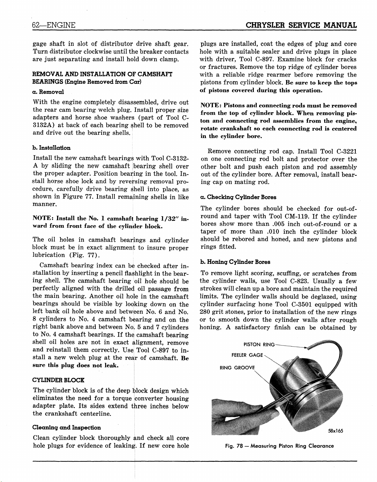
62—ENGINE
CHRYSLER SERVICE MANUAL
gage shaft in slot of distributor drive shaft gear.
Turn distributor clockwise until the breaker contacts
are just separating and install hold down clamp.
REMOVAL AND INSTALLATION OF CAMSHAFT
BEARINGS (Engine Removed from Car)
a. Removal
With the engine completely disassembled, drive out
the rear cam bearing welch plug. Install proper size
adapters and horse shoe washers (part of Tool C3132A) at back of each bearing shell to be removed
and drive out the bearing shells.
b.
Installation
\
Install the new camshaft bearings with Tool C-3132A by sliding the new camshaft (bearing shell over
the proper adapter. Position bearing in the tool. In-
stall horse shoe lock and by reversing removal pro-
cedure, carefully drive bearing sliell into place, as
shown in Figure 77. Install remaining shells in like
manner.
NOTE: Install the No. 1 camshaft bearing 1/32" inward from front face of the cylinder block.
The oil holes in camshaft bearings and cylinder
block must be in exact alignment to insure proper
lubrication (Fig. 77).
Camshaft bearing index can be checked after in-
stallation by inserting a pencil flashlight in the bearing shell. The camshaft bearing oil hole should be
perfectly aligned with the drilled oil passage from
the main bearing. Another oil hole in the camshaft
bearings should be visible by looking down on the
left bank oil hole above and between No. 6 and No.
8 cylinders to No. 4 camshaft bearing and on the
right bank above and between NoL 5 and 7 cylinders
to No. 4 camshaft bearings. If the; camshaft bearing
shell oil holes are not in exact Alignment, remove
and reinstall them correctly. Use| Tool C-897 to install a new welch plug at the reajr of camshaft. Be
sure this plug does not leak.
plugs are installed, coat the edges of plug and core
hole with a suitable sealer and drive plugs in place
with driver, Tool C-897. Examine block for cracks
or fractures. Remove the top ridge of cylinder bores
with a reliable ridge rearmer before removing the
pistons from cylinder block. Be sure to keep the tops
of pistons covered during this operation.
NOTE: Pistons and connecting rods must be removed
from the top of cylinder block. When removing pis-
ton and connecting rod assemblies from the engine,
rotate crankshaft so each connecting rod is centered
in the cylinder bore.
Remove connecting rod cap. Install Tool C-3221
on one connecting rod bolt and protector over the
other bolt and push each piston and rod assembly
out of the cylinder bore. After removal, install bearing cap on mating rod.
a. Checking Cylinder Bores
The cylinder bores should be checked for
out-ofround and taper with Tool CM-119. If the cylinder
bores show more than .005 inch out-of-round or a
taper of more than .010 inch the cylinder block
should be rebored and honed, and new pistons and
rings fitted.
b.
Honing Cylinder Bores
To remove light scoring, scuffing, or scratches from
the cylinder walls, use Tool C-823. Usually a few
strokes will clean up a bore and maintain the required
limits.
The cylinder walls should be deglazed, using
cylinder surfacing hone Tool C-3501 equipped with
280 grit stones, prior to installation of the new rings
or to smooth down the cylinder walls after rough
honing. A satisfactory finish can be obtained by
PISTON RING
FEELER GAGE
RING GROOVE
x
CYLINDER BLOCK |
The cylinder block is of the deep lj>lock design which
eliminates the need for a torque converter housing
adapter plate. Its sides extend three inches below
the crankshaft centerline.
Cleaning and Inspection j
Clean cylinder block thoroughly ^nd check all core
hole plugs for evidence of leaking. If new core hole
Fig.
78
— Measuring Piston Ring Clearance
58x165
MyMopar.com
Page 67

CHRYSLER SERVICE MANUAL
ENGINE—63
giving each cylinder wall
with
the
hone
so
that a cross hatch pattern will
20
strokes
obtained.
After honing,
cleaned again
to prevent excessive wear
may
be
safely used
inch
and as
it is
to
remove
high
as .010 to
necessary that
all
traces
of
engine parts. The hone
for
removal
.015 inch
enced operator.
CAUTION
Be sure
after honing.
soap
oughly dried.
gine
all
and
water
oil and
abrasives
It is
If
are
removed from engine parts
recommended that a solution
be
used with a brush
this
is
impossible,
CLEAN cloth. When
wiped with a clean white cloth
clean,
the
bore
is
clean.
c. Cylinder Walls
Cylinder walls which
scratched,
or
worn beyond specified limits should
be rebored. Whatever type
used, boring operation should
with
the
fitting
of
specified clearance
are
pistons
may be
badly scored, scuffed,
of
boring equipment
be
and
maintained.
d. Fitting Pistons
of
of
metal
in 20
abrasives,
and
seconds
the
block
up to .005
by an
experi-
then thor-
and
use SAE 10 en-
the
bore
can be
and be
withdrawn
closely coordinated
rings
in
order that
be
be
of
is
NUT CTOOl)
CONNECTING
58x195A
Fig.
79 — Tool Arrangement of Removing Piston Pin
This measurement
ure
the
side clearance between piston ring
land.
The
clearance should
for
the top
compression ring, .001
the intermediate ring,
ANVIL (TOOL)
PISTON
PIN
ROD
GUIDE-LARGE (TOOL)
is the
same
and
control ring. Starting with
place expander ring
install
oil
control ring. Install
in middle
C-3629
3628
NOTE:
sion ring
and top
for the
for the
Be
MC-3
sure
is to the top of
in the
grooves.
MC-1
and
and
the
mark "Top"
MC-2 engine
MY-1 engine.
piston when
stalled.
PISTON
PILOT (TOOL)
MAIN
SCREW (TOOL)
GUIDE-SMALL
(TOOL)
for all
rings. Meas-
and
be .0015 to .003
to
.0025 inch
.001
to .003 for the oil
the oil
ring expander,
lower ring groove
the
compression rings
Use
ring installer, Tool
and
Tool
on
each compres-
the
ring
ring
inch
for
and
C-
is in-
The piston
The specified clearance between
cylinder wall
The piston diameter should
top
of
bores
down
and
cylinder wall must
is
.0005
skirt 90°
on
used engines should
the
to the
cylinder bore
to
.0010 inch.
piston
and
transverse
be
clean
the
piston
be
measured
pin
axis.
The
be
measured halfway
to the
and dry.
and the
at the
cylinder
engine
crankshaft centerline.
NOTE: Pistons
ured
at
normal room temperature
All service pistons include pins,
in standard
and
and the
cylinder bores should
be
70° F.
and are
available
following oversizes, .005,
meas-
.020
and .040 inch.
e. Fitting Rings
Measure
from bottom
fitted. (An inverted piston
rings down
the
piston ring
of
to
gap
about
cylinder bore
can be
in
two (2)
which
used
inches
it is to be
to
push
insure positioning rings squarely
the
in
the cylinder wall before measuring.) Insert the feeler
stock
in
gap (Fig.
The ring gap should
78).
be
between .013
to
.025 inch.
REMOVAL OF PISTON PIN
Arrange Tool C-3624 parts
pin,
as
shown
screw. Install
anvil over
small
end of
in
Figure 79. Install pilot
the
screw through piston
the
threaded
anvil against
Fig.
80 —
end of the
Removing Piston
for the
the
piston boss.
MAIN SCREW
(TOOL)
removal
of
on the
pin.
piston
main
Install
main screw with
PRESS
PISTON
[58x166
Pin
MyMopar.com
Page 68

64—ENGINE
CHRYSLER SERVICE MANUAL
-«*>^—-—-
58x196 A GUIDE-LARGE (TOOL)
Fig.
81 —
ANVIL (TOOL)
- SPRING
Tool Arrangement
PILOT (TOOL)
PISTON
PISTON
MAIN SCREW
for
Installing Piston
PIN
(TOOL)
GUIDE-SMALL
(TOOL)
Pin
NOTE: Be sure spring is removed from the anvil.
Install nut loosely on the main screw and place the
assembly on a press, as shown in Figure 80. Press
the piston pin out of connecting rod.
NOTE: When the pin falls free from connecting rod,
stop the press to prevent damage to bottom of the
anvil.
Remove the tool from the piston.
INSTALLATION OF PISTON PIN
Check the piston pin fit in the piston. It should be
a sliding fit in the piston at 70
°F.
Piston pins are
supplied in standard sizes only. Lubricate piston pin
holes in the piston and connecting rod.
Arrange the tool parts for installation of piston
pin, as shown in Figure 81. Install the spring inside
the pilot and install the spring and pilot in the anvil.
Install the piston pin over main screw. Place piston,
with "front" up, over pilot so that the pilot extends
Fig.
(TOOL)
83
— Testing
NUT
Fit on
TORQUE WRENCH
SOCKET
ANVfL (TOOt)
MAIN SCREW
(TOOL)
Piston
Pin in
58x168
A
Connecting
Rod
through the piston pin hole. Position connecting rod
over the pilot which extends through the piston hole.
NOTE: Assemble rods to pistons of the right cylinder
bank (2, 4, 6, and 8) with the indent on the piston
head opposite to the larger chamfer on the large bore
end of connecting rod. Assemble the rods to pistons
of the left cylinder bank (1, 3, 5, and 7) with the indent on the piston head on the same side as the large
chamfer on the large bore end of connecting rod.
Install the main screw and piston pin in the pis-
ton, as shown in Figure 81.
Install the nut on puller screw to hold assembly
together. Place assembly on a press, as shown in
Figure 82. Press in the piston pin until piston pin
bottoms on the pilot properly positioning the pin in
the connecting rod. Remove the tool and arrange tool
parts and piston assembly in the same manner, as
shown in Figure 79.
PISTON
Fig.
PIN «-
82 —
Installing Piston
*
-
PRESS
:
lV>A:N
i
'L*-
-
*• f TOOL)
•• - ANVIL ITOOU
SCREW
PISTON
"58x16?
Pin
58x169
Fig.
84
— External Identification
MyMopar.com
Page 69

CHRYSLER SERVICE MANUAL
ENGINE—65
Place the assembly in a vise, as shown in Figure
83.
Attach the torque wrench to nut and check torque
up to 15 foot-pounds torque. If the connecting rod
moves downward on piston pin, reject this connecting rod and piston pin combination. Obtain a connecting rod with proper small end bore diameter
and repeat the installation, and checking procedure.
If connecting rod does not move under 15 foot-
pounds torque, the piston pin and connecting rod
interference is satisfactory, the tool may be removed.
CONNECTING RODS
IMPORTANT
A Maltese Cross stamped on the engine numbering
pad (Fig. 84) indicates that engine is equipped with
a crankshaft which has one or more connecting rods
and main bearing journals finished .001 inch undersize.
The position of the undersize journal or journals will be stamped on machined surface of No. 3
counterweight (Fig. 85).
Connecting rod journals will be identified by the
letter "R" and main bearing journals by the letter
"M."
Thus "M-l" indicates that No. 1 main bearing
is .001 inch undersize.
INSTALLING CONNECTING ROD BEARINGS
NOTE: Fit all rods on one bank until completed. Do
not alternate from one bank to another, because when
the rods are assembled to pistons correctly, they are
not interchangeable from one bank to another.
Each bearing cap has a small "V" groove across the
parting face. When installing the lower bearing shell,
make certain that the "V" groove in shell is in line
with "V" groove in cap. This allows lubrication of
the cylinder wall. The bearing shells should always
be installed so that small formed tang fits into ma-
LETTERS
( 4
chined grooves of rods. The side play should be from
.009 to .017 inch (two rods).
Limits of taper or out-of-round on any crankshaft
journals should be held to .001 inch. Bearings are
available in
.001,
.002, .003, .010 and .012 inch under-
size.
NOTE: Install the bearings in pairs. Do not use a new
bearing half with an old bearing
half.
Do not file the
rods or bearing caps.
CHECKING THE CONNECTING ROD BEARING
CLEARANCE (PLASTIGAGE METHOD)
Connecting rod bearing clearance measurements can
be made by the use of Plastigage with the engine in
the chassis. After removing the connecting rod cap,
wipe off the oil from the journal and inserts. Place
the Plastigage on bearing parallel with crankshaft.
Reinstall the cap and tighten attaching nuts alternately to specified torque.
Remove cap and measure the width of the compressed material with the graduated scale to determine the bearing clearance. Allowable clearance is
from .0005 to .0015 inches. If taper of the com-
pressed material is evident, measure with the grad-
uated scale. If the taper appears to exceed .005 inch,
the journal should be checked with micrometers.
INSTALLING PISTON AND CONNECTING ROD
ASSEMBLY IN CYLINDER BLOCK
Before installing the pistons, rods, and rod assem-
blies in bore, be sure that compression ring gaps are
diametrically opposite one another and not in line
with oil ring gap. The oil ring expander gap should
be toward the outside of the "V" of the engine. The
oil ring gap should be turned toward the inside of
the "V" of engine. Immerse the piston head and
rings in clean engine oil, slide the ring compressor,
Tool C-385, over the piston and tighten with the
special wrench (part of Tool C-385). Be sure the
position of rings does not change during this oper-
ation. Screw the connecting rod bolt protector (part
of Tool C-3221) on one rod bolt, and insert the rod
and piston into cylinder bore.
NOTE: Rotate the crankshaft so that connecting rod
journal is on center of the cylinder bore.
Fig.
85 — Internal Identification
55x162
Attach the puller part of Tool C-3221 on the other
bolt, and guide the rod over the crankshaft journal,
as shown in Figure 86.
Tap piston down in the cylinder bore, using the
MyMopar.com
Page 70

66—ENGINE
CHRYSLER SERVICE MANUAL
CRANKSHAFT JOURNAL
Fig.
86 — Removing and Installing Connecting Rod
handle of a hammer. At the same time, guide connecting rod into position on crankshaft journal. The
notch or groove on the top of the piston must be
pointing toward front of the engine and the larger
chamfer of the connecting rod bore must be installed
toward crankshaft journal fillet. Install the rod caps,
tighten nuts to 45 foot-pounds torque.
CRANKSHAFT MAIN JOURNALS
The crankshaft journals should be checked for excessive wear, taper and scoring. Journal grinding
should not exceed .012 inch under the standard journal diameter. DO NOT grind the thrust faces of No.
3 main bearing. DO NOT nick the crankpin or main
bearing fillets. After regrinding, remove the rough
edges from crankshaft oil holes and clean out all oil
passages.
CRANKSHAFT MAIN BEARINGS
The lower main bearing halves of 1, 2, 4 and 5 numbers are interchangeable, as shown in Figure 87. The
upper main bearing halves of 1, 2, 4 and 5 numbers
are interchangeable. Upper and lower bearing halves
are not interchangeable because the upper bearing
is grooved and the lower is not.
The upper and lower No. 3 bearing halves are
flanged to carry the crankshaft thrust loads and are
not interchangeable with any other bearing halves in
the engine.
NOTE: Bearings that are not badly worn or pitted
must be reinstalled in the same position.
The bearing caps are not interchangeable and
should be marked at removal to insure correct assembly. Bearing shells are available in standard and
the following undersizes: .001, .002, .003, .010 and
.012 inch. Never install an undersize bearing shell
that will reduce the clearance below specifications.
REMOVAL AND INSTALLATION OF THE
MAIN BEARINGS
a. Removal
Remove the oil pan and mark bearing caps before
removal. Remove bearing caps one at a time. Remove
upper half of bearing by inserting Tool C-3059 (Fig.
88) into the oil hole of crankshaft. Slowly rotate
crankshaft clockwise, forcing out upper half of bearing shell.
Checking the Main Bearing Clearance
Plastigage Method. Use the same technique as described in "Checking the Connecting Rod Bearing
Clearance."
CAUTION
If bearings are measured with the engine in the chas-
BEARING
m m m.
Fig.
87 — Main Bearing Identification
>THRUST BEARING
UPPER
LOWER
x!72
INSTALLING •[51x93A
Fig.
88 — Removing and Installing Main
Bearing Upper Shell
MyMopar.com
Page 71

CHRYSLER SERVICE MANUAL
sis,
the
crankshaft must
take
up
clearance between
and
the
crankshaft journal. This
snugging bearing caps
.005
to .015
shell
and
done
to
or bearings,
inch cardboard between lower bearing
journal.
Use
avoid unnecessary strain
or
false reading may
rotate crankshaft while plastigage
be
supported
the
upper bearing insert
can be
of the
adjacent bearings with
extreme caution when this
on the
be
obtained. Do
is
installed.
to remove cardboard before reinstalling
It
is
permissible
bearing shell with
.002 inch bearing shell. Always
ameter bearing half
bearing with a used bearing
bearing half more than
lower bearing
to use one .001
one
standard bearing shell
as the
.001
half.
inch undersize
use the
upper. Never
and
never
inch smaller than
in
order
done
crankshaft
Be
oil pan.
or one
smaller
use a new
use an
to
by
is
not
sure
di-
upper
the
PLUG
GASKET
|CHN»
SPRING
RELIEF VALVE
PLUNGER
58x173
Fig.
SEAL RING
89 — Oil
GASKET
"O"
Pump
BOLTS
AND
RING
and
Filter Assembly
ENGINE—67
WASHERS
OIL FILTER
INNER ROTOR
AND SHAFT
BODY
DRIVE SHAFT
AND GEAR
b.
Installation of the Upper Main Bearing
NOTE:
slightly chamfer
the
the crankshaft counter-clockwise sliding
into position. After
tighten
shaft
OIL
When installing
Start bearing
oil
hole
of
all
caps
end
play should
PAN
(ALL MODELS)
a new
the
sharp edge from
in
place,
and
crankshaft
all
bearings have been fitted,
to 85
foot-pounds torque.
be .002 to .007
upper bearing shell,
the
plain side.
insert Tool C-3059 into
(Fig. 88).
Slowly rotate
the
bearing
The
inch.
crank-
a. Removal
Drain
the oil and
steering linkage from steering
steering linkage
system,
Be sure
supported.
the
exhaust crossover pipe must
the
It
located across
allow enough clearance
pan attaching bolts
only. Disconnect throttle linkage
remove dipstick. Disconnect
arm to
to be
rest
may
the
lowered.
of
exhaust system
be
necessary
to
On
pull
crossmember slightly forward
and
for pan
lower
removal. Remove
the oil pan on MC-1
at
transmission and
the
allow
the
single exhaust
be
removed.
is
sufficiently
the
brake line
to
oil
at carburetor. Rotate the crankshaft until the center-
line
of the
position. Remove
and raise
b.
Installation
front counterweight
the
front engine mounting nuts
the
engine
one
inch. Remove
is in the 10
the oil pan.
o'clock
attaching bolts. Tighten bolts
torque. Lower
mounting nuts
the
and
engine
tighten
to 15
and
install front engine
to 85
foot-pounds torque.
foot-pounds
Connect exhaust pipes (if removed) and steering,
throttle and carburetor linkage. Refer to Transmission Section in this manual. Refill the crankcase.
OIL
PUMP
a. Removal
Remove oil pump attaching bolts and remove pump
and filter assembly from bottom side of the engine.
b.
Disassembly
Remove the filter base and oil seal ring. Remove
pump rotor and shaft and lift out the outer pump
rotor. Remove oil pressure relief valve plug and lift
out spring and plunger (Fig. 89).
c.
Inspection and Repair
Clean all parts thoroughly. The mating face of oil
IfRAIGHT
/
EDGE
NOTE:
bottom
machined surface
Check
of
the
strainer must
alignment
be on a
of the
cylinder block.
strainer should touch bottom
pan thoroughly
and
install
new
of the oil
strainer.
horizontal plane
The
of the oil pan.
gasket,
oil pan and
The
foot
Clean
of
FEELER
GAUGE
Fig.
90 —
Checking
Oil
Pump Cover Flatness
MyMopar.com
Page 72

68—ENGINE
CHRYSLER SERVICE MANUAL
STRAIGHT EDGE
FEEIER GAUGE
Fig.
93 — Measuring Clearance over Rotors
51x66A
Fig.
91 —Measuring Outer Rotor Thickness
DIAMETER
pump cover should be smooth. Replace cover if it is
scratched or grooved.
Lay a straight edge across the oil pump cover sur-
face (Fig. 90). If a .0015 inch feeler gauge can be
inserted between the cover and straight edge, the
cover should be replaced. If outer rotor length meas-
ures less than .943 inch (Fig. 91), and diameter less
than 2.469 inches, replace outer rotor.
If the pump inner rotor length measures less than
.943 inch (Fig. 92) a new pump rotor should be in-
stalled.
Slide outer rotor and inner rotor into pump body
and place a straight edge across the face (between
the bolt holes), as shown in Figure 93.
If a feeler gauge of more than .004 inch can be
inserted between rotors and straight edge, replace
pump body. Remove pump inner rotor and shaft
leaving the outer rotor in pump cavity. Press the
outer rotor body to one side with fingers and measure the clearance between outer rotor and pump
body (Fig. 94). If measurement is more than .012
inch replace the oil pump body. If clearance between
inner rotor and outer rotor (Fig. 95) is more than
.010 inch, replace the inner and outer rotors.
Check the oil pump relief valve plunger for scoring and for free operation in its bore. If the plunger
is scored, replace the plunger. The spring should
conform to specifications on chart. If, for any reason, the spring has to be replaced, the same color
spring should be used. An exception is where oil
pressure is either above or below specifications.
When assembling oil pump, be sure to use new oil
seal rings between filter base and body. Tighten the
attaching bolts to 35 foot-pounds torque.
Installation
Install the oil pump on engine.
OUTER ROTOR
58x176
Fig.
92 — Measuring Inner Rotor Thickness
51x67A
Fig.
94 — Measuring Outer Rotor Clearance
.,- OUTER ROTOR
-INNER ROTOR
FEELER
GAUGE
Fig.
95 — Measuring Clearance Between Rotors
MyMopar.com
58x1,77
Page 73

CHRYSLER SERVICE MANUAL
OIL FILTER
ASSEMBLY
TOOL
58x239
Fig.
96 — Removing
RELIEF VALVE SPRING CHART
Oil
Filter with Tool
ENGINE—69
*
58x238
Fig.
98 — Trimming Rear Main Bearing
Lower Oil Seal
Free Loaded
Color
Gray(Lt.)
Red (Std.)
2.19 1.60
2.29 1.60
Brown (Hvy.)....
REMOVAL AND INSTALLATION OF OIL FILTER
Length Length
2.39 1.60
The oil filter should be replaced every
coincide with
Use care so as not to damage transmission
an
engine oil change
Compression
Pounds
11.85
14.85
17.9
5,000
as
follows:
to
12.85
to
15.85
to 18.9
miles
oil
cool-
to
er lines. Using Tool C-3654, unscrew the filter from
base on bottom side on engine and discard. Wipe the
base clean. Screw
new
filter
on
base,
as
shown
in
Figure 96, until gasket on filter contacts base. Tighten
y2 turn more by hand. Start engine and check
for
leaks.
BRIDGE
(PART
OF
TOOL)
REPLACEMENT OF THE REAR MAIN BEARING
OIL SEAL (Crankshaft Removed)
Remove Allen screws and seal retainer. Install a new
rear main bearing
oil
seal
in the
cylinder block
so
that both ends protrude. Tap seal down into position,
using Tool C-3625 until the tool
bore.
Hold tool in this position and cut
seal that extends above the block
NOTE:
Be
sure
the
Install a new seal
bridge
in
the seal retainer so that
ends protrude (Fig. 97). Install bridge
is
seated
on
is
removed from tool.
in
off
portion of
both sides.
on
bearing
the
tool
and
tap the seal down into position with Tool C-3625 un-
til tool is seated. Trim
protrudes above
side seals
tainer
in
grooves
and
tighten screws
off
the cap
in
seal retainer. Install seal
OUTER
the portion
of
the seal that
(Fig. 98). Install
to 30
foot-pounds torque.
CUP
INSTALL INDEX MARK
TOWARD ENGINE
the two
re-
SEAL
SEAL
RETAINER
SIDE
GROOVES
Fig.
97 — Installing Rear Main Bearing
Lower Oil Seal
58x237
INSULATOR
BOLT ASSEMBLY
58x33
AND
FRAME BRACKET
Fig.
99 — Right Front Engine Support
-.' •£
LOCKWASHER
L- PLATE
NUT
MyMopar.com
Page 74

70—FUEL
AND
EXHAUST SYSTEM
CHRYSLER SERVICE MANUAL
FRONT ENGINE MOUNTS
a. Removal
Disconnect throttle linkage at transmission and at
carburetor. Remove the nuts, washers, plates from
front engine mounts and raise the engine sufficiently
enough to remove the insulator and stud assembly.
b.
Installation
Install the insulator and stud assembly with the index mark on the insulator facing toward the engine,
as shown in Figure 99.
Lower the engine aligning the stud with the slots
in frame brackets.
CAUTION
Be sure
bottom
engine, and tighten nuts to 85 foot-pounds torque.
Connect throttle linkage to transmission and to car-
buretor. Refer to Transmission Section in this manual for adjustment.
the
insulator stud does
of the
Install plates, washers and nuts. Neutralize the
slot
in the
not
frame bracket.
Section VIII
FUEL
Model
FUEL PUMP
Make Carter
Model M-2769S
Type Mechanical
Driven
Pump Pressure (pounds)
By
Camshaft
AND
DATA
5 to 7
AND
EXHAUST SYSTEM
SPECIFICATIONS
interfere with
MG-1
the
CARBURETOR
Type Dual Throat Downdraft
Model BBD-2795S-2872S
ADJUSTMENTS
Idle Mixture (both screws) One full turn open
Idle Speed. . 500
Fast Idle
Fast Idle
Choke Unloader
Accelerator Pump Travel 1 in.
Float Setting
CHOKE
Control Cross over type
Setting
Fast Idle Speed Setting 1375
FUEL PUMP
Make
Model
Type
Driven
Pump Pressure (pounds)
.017"
Cam On
On
Model
By
J
%2 + or —%
34
MG-2,
rpm
Index
inch
+ or
Index
to
1425
MG-3
and MY-1
Carter
M-2769S
Mechanical
Camshaft
5
to 7
—l{i
rpm
MyMopar.com
Page 75

CHRYSLER SERVICE MANUAL
ENGINE—41
(b) Remove the two screws and remove bezel by
lifting bezel outward and upward (to clear
metal retaining tabs).
(c) Expose internal mechanism of mirror assem-
bly by lifting top portion of back cover up-
ward (to clear metal retaining tabs) and
moving back cover rearward over mirror support. Move back cover rearward only far
enough to provide access to potentiometer
adjusters (Fig. 38).
(d) To increase sensitivity of the "City" position,
turn the arm of the potentiometer marked
"City" in the direction indicated by the arrow.
(e) To increase sensitivity for "Hi-way" driving,
turn the arm of the potentiometer marked
"Hi-way" in the direction indicated by the
arrow.
Section VII
ENGINE
DATA AND SPECIFICATIONS
NOTE: To decrease sensitivity of either or both the
potentiometers, turn potentiometer arms in the di-
rection opposite to direction indicated by arrow.
(f) Replace back cover by positioning back cover
over the two metal tabs and aligning screw
holes in bottom of cover with threaded holes
in mirror support.
(g) Install bezel by aligning slots at top of bezel
with metal tabs and aligning screw holes in
bottom of bezel with threaded holes in mirror support replace screws (Fig. 36) and
tighten securely.
(h) Replace plastic switch knob.
(i) Adjust mirror to desired position and test
operation of unit.
ENGINE
Type
Number of Cylinders
Bore—MC-1,
Stroke
Piston Displacement—MC-1, MC-2
Compression Ratio
Compression Pressure at 150 rpm (plugs removed) Wide Open Throttle
Maximum Variation Between Cylinders (any one engine)
Firing Order
CYLINDER NUMBERING
Left Bank
Right Bank
CRANKSHAFT
Type
Bearings
Journal Diameter
Crank Pin Diameter
Maximum Out-of-Round Permissible
Number Main Bearings
Diametral Clearance Desired
End Play
Thrust Taken By
Finish at Rear Seal Surface
Interchangeability of Bearings
MC-3,
MC-2
MY-1
MC-3,
MY-1
90° V
8
4.031"
4.188"
3.750"
383 cu. in.
413 cu. in.
10.0 to 1
150 to 180 lbs.
25 lbs.
1-8-4-3-6-5-7-2
1-3-5-7
2-4-6-8
Fully Counter-Balanced
Steel Backed Babbitt
2.7495 to 2.7505"
2.374 to 2.375"
.001"
5
.0005 to .0015"
.002 to .007"
No.
3 Main Bearing
Diagonal Knurling
Upper Nos. 1, 2, 4, 5
Lower Nos. 1, 2, 4, 5
MyMopar.com
Page 76

42—ENGINE
CHRYSLER SERVICE MANUAL
ENGINE (Cont'd)
MAIN BEARINGS (Service) All Available in Standard and the following
Undersizes .001, .002, .003, .010, .012"
CONNECTING RODS AND BEARINGS
Type Drop Forged "I" Beam
Length (Center to Center) 6.766—.770"
Weight (less bearing shells) 29.4 oz.
Bearings Steel-Backed Babbitt
Diameter and Length 2.375 x .927"
Diametral Clearance Desired .0005 to .0015"
Maximum Allowable before Reconditioning .0025"
Side Clearance .009 to .017"
Bearings for Service Standard .001, .002, .003,
.010,
.012" U.S.
Piston Pin Bore Diameter
CAMSHAFT
Drive Chain
Bearings Steel Backed Babbitt
Number 5
Thrust Taken by Cylinder Block
Diametral Clearance .001 to .003"
Maximum Allowable before Reconditioning .005"
1.0925
to 1.0928"
CAMSHAFT BEARING JOURNALS
Diameter
No.
1 1.998 to 1.999"
No. 2 1.982 to 1.983"
No. 3 1.967 to 1.968"
No. 4 1.951 to 1.952"
No. 5 1.748 to 1.749"
CAMSHAFT BEARINGS
Diameter (after reaming)
No.
1 2.000 to
No.
2 1.984 to
No.
3 1.969 to
No.
4 1.953 to
No.
5 1.750 to 1.751"
TIMING CHAIN
Adjustment None
Number of Links , 50
Pitch .50"
Width .88"
TAPPETS
Type Hydraulic
Clearance in Block .0005 to .0015"
Body Diameter .9040 to .9045"
Clearance Between Valve Stem and Rocker Arm Pad Dry Lash
.060 to .210"
2.001"
1.985"
1.970"
1.954"
PISTONS
Type Horizontal Slot w/Steel Struts
Material Aluminum Alloy Tin Coated
MyMopar.com
Page 77

CHRYSLER SERVICE MANUAL
ENGINE—43
ENGINE (Cont'd)
Land Clearance (diametral)
Clearance at Top of Skirt
Weight (std. through .040 oversize)
MC-1,
MC-2
MC-3,
MY-1
Piston Length (overall)
Ring Groove Depth
No.
1—MC-1
No.
2—MC-1
No.
3—MC-1
Pistons for Service
PISTON PINS
Type
Diameter
Length
Clearance in Piston
Interference in Rod
Piston Pins for Service. . .
Direction Offset in Piston
PISTON RINGS
Number of Rings per Piston.
Compression
Oil
Width of Rings
(Compression)
(Oil)
Piston Ring Gaps (all)
& MC-2
MC-3 & MY-1
&MC-2
MC-3 & MY-1
& MC-2
MC-3 & MY-1
.041 to .047"
.0005 to .0010"
724 gms.
780 gms.
3.95"
.213"
.216"
.213"
.216"
.195"
.200"
Std. .005, .020, .040" O.S.
Press Fit in Rod
1.0935
to
1.0937"
3.4440
to 3.450"
.00045 to .00075"
.0007 to .0012"
Standard Only
Toward Right Side of Engine
3
2
1
.0775 to .0780"
.1860 to .1865"
.013 to .025"
RING SIDE CLEARANCE
(Compression)
Upper
Intermediate
(Oil)
VALVES—Intake
Material
Head Diameter
Length (to top of valve face)
Stem Diameter
Stem to Guide Clearance
Maximum Allowable Before Reconditioning.
Angle of Seat
Adjustment
Lift
VALVES—Exhaust
Material
Head Diameter.
MC-1,
MC-3,
MC-2
MY-1
.0015 to .0030"
.0015 to .0030"
.0010 to .0030"
Silicon—Chromium Steel
1.95"
2.08"
4.79"
.372 to .373"
.001 to .003"
.004"
45°
None
.389"
Nitrogen Treated Manganese
Chromium—Nickel Steel
1.60"
MyMopar.com
Page 78

44—ENGINE
CHRYSLER SERVICE MANUAL
ENGINE (Cont'd)
Length (to top of valve face) 4.79"
Stem Diameter .371 to .372"
Stem to Guide Clearance .002 to .004"
Maximum Allowable Before Reconditioning .006"
Angle of Seat 45°
Adjustment None
Lift .389"
VALVE SPRINGS
Number 16
Free Length 2.34"
Load when Compressed to (valve closed)
Load when Compressed to (valve open)
Valve Springs I.D 1.010 to
CYLINDER HEAD
Number Used 2
Combustion Chamber Wedge Type
Valve Seat Runout (maximum) .002'
Intake Valve Seat Angle 45
Seat Width (finished) .060 to .085"
Exhaust Valve Seat Angle 45°
Seat Width (finished) .040 to .060"
Cylinder Head Gasket Compressed (thickness) .022"
1.860"
1.470"
@ 95 —105 lbs.
@ 188—252 lbs.
1.030"
C
•o
ENGINE LUBRICATION
Pump Type Rotary, Full Pressure
Capacity (qts.) 5*
Pump Drive Camshaft
Operating Pressure at 40 to 50 mph 45 to 70 lbs.
Pressure Drop Resulting from Clogged Filter 7 to 9 lbs.
*When Filter Element is Replaced, add 1 qt.
TIGHTENING REFERENCE
Torque Thread
Foot-Pounds Size
Connecting Rod Nut—Plain
Connecting Rod Nut—CST (Black)
Cylinder Head Bolt
Main Bearing Cap Bolt
Spark Plug
Camshaft Lockbolt
Carburetor to Manifold Nut
Chain Case Cover Bolt
Torque Converter Housing Bolt
Clutch Housing Bolt
Crankshaft Rear Bearing Seal Retainer
Crankshaft Bolt
Cylinder Head Cover Stud and Nut
Distributor Vacuum Line Tube Nut
Distributor Clamp Bolt
45
40
70
85
30
35
7
15
30
30
30
135
40 in.-lbs.
95 in.-lbs.
15
^8-24
^-24
%-14
J4-13
14 mr
%>—14
%-24
5
/i6-18
•HJ-16
^-16
%~1Q
%-W
J4-28
^-24
^fi-18
MyMopar.com
Page 79

CHRYSLER SERVICE MANUAL
TIGHTENING REFERENCE (Cont'd)
Engine Front Mounting to Frame Nut 85
Engine Front Mounting to Block Nut „ 45
Exhaust Manifold Bolt „ 30
Exhaust Pipe Flange Nut 40
Exhaust Pipe Clamp Bolt 20
Exhaust Pipe Support Clamp Bolt 20
Fan Attaching Bolt 15-18
Fan Belt Idler Pulley Nut . 45
Fan Belt Idler Pulley Bracket Bolt 30
Flywheel Housing to Cylinder Block Bolt 50
Flywheel Housing Cover Bolt , 7
Fuel Pump Attaching Bolt 30
Generator Bracket Bolt 50
Generator Mounting Nut 20
Generator Adjusting Strap Bolt . 15
Generator Adjusting Strap Mounting Bolt 30
Intake Manifold Bolt 40
Manifold Heat Control Counterweight Bolt 50 in.-lbs.
Oil Pan Drain Plug 35
Oil Pan Bolt 15
Oil Pump Cover Bolt 15
Oil Pump Attaching Bolt 35
Oil Filter Attaching Stud 30
Rocker Shaft Bracket Bolt 30
Starter Mounting Bolt 50
Vibration Damper Bolt 15
Valve Tappet Cover End Bolt 8
Water Pump to Housing Bolt 30
Water Pump Housing to Cylinder Block Bolt 30
A/C Compressor to Engine Bolt 30
ENGINE—45
#10-32
56-16
ENGINE
The new V-8 Engine, as shown in Figure 39, 40 and
41,
ia one of the finest, most efficient engines to be
designed by Chrysler Engineering. It contains many
weight reducing features.
Some of the new features, as shown in Figures
42,
43 and 44, are in-line overhead valves, wedge
shaped combustion chambers, full length cylinder
water jackets, rigid crankshaft and series flow cool-
ing system. In addition, the volume of coolant in the
engine has been reduced to improve engine warm
up.
The ignition distributor is located at the upper
front end of the engine for easier servicing.
The lubrication system consists of an externally
mounted rotor type oil pump of greater capacity, full
flow oil filter and a series of passages where the oil
is delivered to the engine. The oil filter can be installed by hand.
The engine has 10:1 compression ratio, is equipped
with a dual carburetor on the Windsor Model
(MC-1),
els,
tional smoothness and performance throughout the
entire speed range.
MINOR TUNE UP
A periodic engine tune up will assure maximum engine performance and fuel economy. The following
procedures should be followed when performing
minor engine tune up.
sary and clean and tighten battery connections.
Clean and adjust the spark plugs (.035 inch gap).
Tighten to 30 foot-pounds torque with Tool C-3054.
Adjust the distributor contact points (.015 to .018
and a 4-barrel carburetor on all other mod-
and uses premium fuel. The engine has excep-
Check battery specific gravity, add water if neces-
MyMopar.com
Page 80

46—ENGINE
CHRYSLER SERVICE MANUAL
Fig.
39 — Chrysler Engine Assembly
59x151
Fig.
40 — Engine End Sectional View
59x54
MyMopar.com
Page 81

CHRYSLER SERVICE MANUAL
ENGINE—47
inch gap). Install new points if necessary. Check the
distributor cap for cracks and corrosion,. Inspect the
rotor, rotor spring and plunger. Inspect the distributor to spark plug wires for brittle, cracked or
frayed insulation. Inspect small lead wires for tightness,
or damaged insulation. Check for excessive
play in distributor vacuum advance plate bearing.
Install a new plate if necessary. Reset the ignition
timing. Inspect accessory belt drives referring to
"Accessory Belt Drives," for proper adjustments.
Tighten the carburetor flange nuts to 7 foot-pounds
torque. Set carburetor idle mixture adjustment. Ad-
just the throttle stop screw so engine idles at 450 to
500 rpm. Check manifold heat control valve in the
right exhaust manifold for proper operation and
apply Manifold Heat Control Valve Solvent Part
Number 1879318 to the bushing and shaft, as shown
in Lubrication Section.
MAJOR
TUNE
UP
Perform all the steps of a "Minor Tune Up" and in
addition, the following procedures should be followed when performing Major Engine Tune Up.
Tighten the manifold nuts. Perform the cylinder
compression test. Compression pressures can be read
from the top side of engine without interference
using a 30 degree bend extension on, the gauge. The
compression should not vary more than 25 pounds
between cylinders.
Refer to specifications for compression pressures.
Test the coil, and condenser. Inspect the primary and
secondary wires. Service the air cleaner — DO NOT
WASH OR OIL. Service more frequently under severe dusty conditions. Replace air cleaner filter cart-
ridge every 15,000 miles. Test fuel pump for
pressure and vacuum. Refer to Fuel Section Specifications. Perform a combustion analysis. Adjust the
carburetor. Road test the car as a final check.
REMOVAL OF
THE
ENGINE ASSEMBLY (From Car)
Drain the cooling system and remove the battery.
Remove the fan shroud and radiator. Scribe the outline of hinge brackets on hood to assure proper adjustment when installing. Remove the hood. Disconnect fuel lines and wires attached to engine units.
Fig.
41 —
Engine Side Sectional View
58x135
MyMopar.com
Page 82

48—ENGINE
CHRYSLER SERVICE MANUAL
O>
MyMopar.com
Page 83

CHRYSLER SERVICE MANUAL
Fig.
42 — Engine External Parts
1.
Carburetor Air Cleaner
2.
Coil
3. Vacuum Line
4.
Wiring Harness (bracket)
5. Fuel Line
6. Tappet Chamber Cover and Intake
Manifold Gasket
7. Reinforcement, silencer and
Retainer
8. Wiring Harness (brackets)
9. Oil Filler Cap
10.
Rocker Cover L
11.
Rocker Cover Gasket L
12.
Spark Plug Heat Shield
13.
Cylinder Head L
14.
Oil Level Indicator
15.
Exhaust Manifold L
16.
Oil Level Indicator Tube
17.
Cylinder Head Gasket
18.
Distributor Clamp
19.
Water Pump Housing Gasket
20.
Oil Pump Housing Gasket
21.
Outlet Elbow
22.
Outlet Elbow Gasket
23.
Thermostat
24.
Temperature Sending Unit
25.
Water Pump Housing
26.
Water Pump Body Gasket
27.
Water Pump Body
28.
Hub
29.
Water Pump Pulley
30.
Bolt
31.
Washer
32.
Crankshaft Pulley
33.
Vibration Damper
34.
Oil Filter
35.
Oil Pump
36.
Chain Case Cover
37.
Chain Case Cover Gasket
38.
Oil Pan Gasket
39.
Oil Pan
40.
Chain Case Cover Oil Seal
41.
Cylinder Block
42.
Oil Screen Suction Pipe
43.
Fuel Pump
44.
Fuel Pump Gasket
45.
Exhaust Manifold
46.
Starter
47.
Solenoid
48.
Torque Converter Housing Dust Shield
49.
Generator Bracket
50.
Ring Gear
51.
Torque Converter
52.
Torque Converter Housing
53.
Manifold Heat Control Valve
54.
Spark Plug
55.
Spark Plug Heat Shield
R
ENGINE—49
56.
Cylinder Head R
57.
Crankcase Vent Tube
58.
Rocker Cover Gasket
59.
Rocker Cover
60.
Wiring Harness (brackets)
61.
Crankcase Vent Tube Cap
62.
Generator
63.
Distributor Gasket
64.
Distributor
65.
Wires
66.
Reinforcement
67.
Generator Adjusting Strap
68.
Intake Manifold
69.
Automatic Choke
70.
Control Spring Bracket
71.
Carburetor Gasket
72.
Carburetor
73.
Carburetor Air Cleaner Gasket
R
R
Remove the air cleaner and carburetor. Attach the
engine lifting fixture Tool C-3466 to carburetor
flange studs on the intake manifold and attach a
chain hoist to the fixture eyebolt. Disconnect the pro-
peller shaft, wires and linkage at transmission. Disconnect exhaust pipes at manifolds. Be sure the
exhaust system is sufficiently supported while the en-
gine is removed. Remove rear crossmember to transmission support attaching bolts.
NOTE: Place a roUaway jack under the transmission
RIGHT BANK
LUBRICATION
NO.
4 CAMSHAFT
BEARING
to relieve weight from the crossmember. Place a
wood block between jack and transmission to avoid
damaging transmission oil pan.
The jack supports the weight of rear of engine
and must be able to roll with the power plant as it is
removed from the chassis. Remove rear crossmember engine support. Remove front engine mounting
nuts.
Raise the engine with chain hoist and work
the engine out of the chassis. Remove transmission.
Place the engine in repair stand C-3167 and Adapter
ROCKER
SHAFT
ROCKER ARM
RIGHT MAIN OIL GALLERY
OIL FILTER
Oil PUMP RELIEF VALVE
Fig.
OIL PRESSURE
43 — Engine Oiling System
LEFT ROCKER SHAFT
59x24
MyMopar.com
Page 84

50—ENGINE
CHRYSLER SERVICE MANUAL
WASHER
CAMSHAFT
BOLT\
RETAINER
SPACER
ROCKER
BRACKET
GEARAND SHAFT
SPROCKET
CHAIN
BOLT
(SERVICED IN PACKAGE)
OIL SEAL
RETAINER -
SCREW
CAP
SCREW
SCREW
NUT
CAP
Fig.
44 — Engine Internal Parts
BEARING
CRANKSHAFT
SPROCKET
OIL SLINGER
_~-—~—SCREW
CAP {SERVICED IN ROD)
59x53
MyMopar.com
Page 85

CHRYSLER SERVICE MANUAL
3662 for disassembly using the transmission mounting bolts.
INSTALLING THE ENGINE ASSEMBLY (In Car)
Remove the engine from repair stand and install
transmission. Install the engine lifting fixture Tool
C-3466 and attach the chain hoist to fixture eyebolt.
Raise the engine. Lower the engine carefully into
the car until front and rear of engine are approxi-
mately positioned. Place a rollaway jack under the
transmission to support the weight of rear of the
engine. Install the engine rear support crossmember.
Position the engine and install the nuts at front en-
gine mounts. Position and install rear engine sup-
port bolts and remove the jack, hoist and engine
lifting fixture.
Install the carburetor, fuel lines, wiring and link-
age.
Install the radiator, fan shroud and radiator
hoses.
Connect exhaust pipes, using new gaskets.
Install the hood, being sure to align hood by the
scribe marks placed on the inside of hood at disassembly. Connect the propeller shaft at the transmission. Connect linkage and wires. Be sure all drain
cocks are closed, and fill cooling system. Fill the
engine crankcase and transmission. Refer to the lubrication Section for quantities and lubricants to use.
Check the entire system for leaks and correct as
necessary.
NOTE: Whenever an engine has been rebuilt and a
new camshaft and/or new tappets have been installed,
add one quart of factory recommended oil additive
to engine oil to aid break-in (MoPar Engine Oil Additive, Part No. 1643234). The oil mixture should
be left in engine for a minimum of 500 miles, and
drained at the next normal oil change.
INTAKE VALVES
&&^5>-
k:a
EXHAUST
VALVES
ENGINE—51
58x137
Fig.
46 — Tightening Sequence
Start the engine and run until normal operating"
temperature is reached. Check the timing and adjust
carburetor as necessary. Road test the car.
CYLINDER HEADS
The chrome alloy cast iron cylinder heads as shown
in Figure 45 are held in place by 17 bolts. The spark
plugs enter the cylinder head horizontally and are
located at the wide edge of the combustion, chambers.
a. Removal
Drain the cooling system. Remove generator, carburetor air cleaner and fuel line. Disconnect the accel-
erator linkage. Remove the vacuum control tube at
carburetor and distributor. Disconnect the distrib-
utor cap, coil wires and heater hose. Disconnect the
heat indicator sending unit wire. Remove spark
plugs located under the manifolds. Remove the in-
take manifold, ignition coil and carburetor as an
assembly. Remove the tappet chamber cover. Remove cylinder head covers and gaskets.
NOTE: On air conditioned cars, number eight cyl-
inder exhaust valve must be open to allow clearance
between the right bank cylinder head cover and the
heater housing.
Remove the generator. Remove exhaust manifolds.
Remove the rocker arms and shaft assembly. Remove the push rods and place them in their respective slots in holder Tool C-3068. Remove the 17 head
bolts from each cylinder head and remove cylinder
heads.
Place cylinder head in holding fixture Tool
C-3626.
Fig.
45 — Cylinder Heads
58x136
b.
Installation
Clean the gasket surfaces of cylinder block and cyl-
inder head. Check all surfaces with a straight edge
if there is any reason to suspect leakage. Coat the
MyMopar.com
Page 86

52—ENGINE
CHRYSLER SERVICE MANUAL
EXHAUST MANIFOLD - RiGHT
, TOOL
mam*
V> X 1
M
Fig.
47 — Checking Cylinder Head Bolt Torque
new gaskets with a suitable sealer, MoPar Part
Number 1122893. Install
heads.
Install cylinder head bolts. Starting
center, tighten
pounds torque
all
cylinder head bolts
in
sequence,
and using Tool C-3666
Figure 47.
Repeat
the
procedure, retightening
to 70 foot-pounds torque. Inspect push rods
place worn
small ends
rod,
as
or
in
shown
bent rods. Install push rods with
tappets maintaining alignment using
in
Figure 48.
Install the rocker arm and shaft assembly starting
each push
rod
into
its
NOTE: Use extreme care
pounds torque,
so the
down to their operating length. Bulged tappet bodies,
CYLINDER HEAD INTAKE PUSH RODS
ASSEMBLIES
the
gaskets
as
shown
to
check torque,
and
in
all
respective rocker
in
tightening bolts
tappets have time
cylinder
at top
to 70
Figure
as
shown
head bolts
and re-
arm
socket.
30
to
bleed
foot-
46,
in
the
foot-
LOCATING ARROW ROCKER ARMS-RIGHT
;
• . ROCKER ARMS-RIGHT
58xl?9
Fig.
bent push rods,
may result
if
the tappets are forced down too rapidly.
LOCATIMOARROW
49 — Rocker Arms Installed
and
permanently noisy operation
i
Place the new cylinder head cover gaskets in posi-
tion
and
install cylinder head covers. Tighten
the
bolts to 40 inch-pounds torque. Install exhaust manifolds and tighten the bolts
Adjust spark plugs
plugs,
and
tighten
to
to 30
Tool C-3054. Install
tighten end bolts
to 8
Install intake manifold, carburetor
coil
as an
assembly and tighten manifold bolts
to
30 foot-pounds torque.
.035 inch
gap and
install
foot-pounds torque with
the
tappet chamber cover
foot-pounds torque (Fig.
and
the
and
49).
ignition
to 40
food-pounds torque. Install the distributor cap. Con-
nect
the
coil wire, heat indicator sending unit wire,
accelerator linkage, spark plug cables and insulators.
Install
the
vacuum tube from carburetor
to
distributor. Install generator and tighten generator bracket
bolts to 50 foot-pounds torque, and generator mounting nut to 20 foot-pounds torque. Install the fuel line
and carburetor
Adjust belt tensions
Drives"
in
air
cleaner. Fill
as
outlined
this supplement.
the
cooling system.
in
"Accessory Belt
INSTALLING
ROD
EXHAUST PUSH RODS "58x138
Fig.
48 — Push Rods Installed
-BRACKETS-
OIL FEED GROOVE
THIS SIDE
58x140
Fig.
50 — Rocker Arms & Shaft Assembly
OIL FEED
GROOVE
THIS SIDE
SPACERS-
MyMopar.com
Page 87

CHRYSLER SERVICE MANUAL
ENGINE—53
ROCKER ARMS
The rocker arms
AND
SHAFT ASSEMBLY
are of
stamped steel
and are arranged on one rocker arm shaft, per cylinder head.
The push rod angularity tends
to
force the pairs of
rocker arms toward each other where oilite spacers
carry the side thrust
ets attach each rocker shaft
at
each rocker arm. Five brack-
to
the cylinder head.
a. Removal
Remove cylinder head cover and gasket. Remove the
bolts that attach rocker
arm
support brackets
to
cylinder head and remove the rocker arms, brackets
and shaft as an assembly.
If the rocker arm assemblies have been disassem-
bled
for
cleaning, inspection,
to Figure 49 and 50
b.
Installation
NOTE: The right and left rocker arms must be in-
stalled on rocker shaft, as shown in Figure 49. The
stamped arrow on rocker shaft must be on top and
the arrow must point toward the push rod socket of
the rocker arm. This is necessary to provide proper
lubrication to the rocker assemblies. The two wide
brackets must be installed with the oil feed grooves
facing the push rod side of rocker arm, as shown in
Figures 49 and 50.
Install
the
rocker arms, brackets,
for
or
replacement, refer
proper reassembly.
and
shaft
as-
sembly.
NOTE: Use extreme care
in
tightening the bolts
so
"OOU
58x142
Fig.
52 —
Using Sleeve Tool
in
Checking Wear
that tappets have time to bleed down to their operating length. Bulged tappet bodies, bent push rods and
permanent noisy operation may result
if
the tappets
are forced down too rapidly.
Tighten the bolts
VALVES
AND
to
30 foot-pounds torque.
VALVE SPRINGS
Valves are arranged in-line in the cylinder heads and
inclined 30° outward from vertical. Intake and
ex-
haust valves operate in guides that are integral with
the heads.
a. Removal
With
the
cylinder head removed, compress valve
springs using
Tool.
C-3422, as shown in Figure 51.
CYLINDER HEAD
ASSEMBLY
Fig.
51
— Compressing Valve Spring
TOOL
REPAIR" STAND
(TOOL)
58x141
Remove
the
valve retaining locks, valve spring
retainers, valve stem cup seals and valve springs. Remove the burrs from valve stem lock grooves to pre-
vent damage
to
the valve guide when valves are re-
moved.
b.
Valve Inspection
Clean
the
valves thoroughly,
and
discard burned,
warped and cracked valves. Measure valve stems for
wear. Intake valve stem diameter should measure
.372
to
.373 inch
should measure .371 to .372 inch.
and
exhaust valve stem diameter
If
the wear exceeds
.002 inch, replace the valve. Remove carbon and varnish deposits from
the
inside
of
valve guides with
cleaner, Tool C-756.
Measure
the
valve stem guide clearance
as fol-
lows : Install sleeve Tool C-3026 over the valve stem,
as shown in Figure 52, and install valve.
MyMopar.com
Page 88

54—ENGINE
CHRYSLER SERVICE MANUAL
VALVE
58x143
Fig.
53 — Measuring Guide Wear
The special sleeve places the valve at the correct
height for checking with a dial indicator. Attach the
dial indicator Tool C-3339 to cylinder head and set
it at right angle of the valve stem being measured
(Fig. 53).
Move valve to and from the indicator. The total
dial indicator reading should not exceed .010 inch on
intake valves, and .014 inch on exhaust valves. Ream
the guides for valves with oversize stems if dial indi-
cator reading is excessive or if the stems are scuffed
or scored.
Service valves with oversize stems are available in
.005,
.015 and .030 inch oversizes. Reamers to accom-
modate the oversize valve stem are as follows: Ream-
er Tool C-3433 (.379 to .380 inch) Reamer Tool C3427 (.404 to .405 inch). Slowly turn reamer by hand
and clean guide thoroughly before installing new
valve.
CAUTION
Do not attempt to ream the valve guides from standard directly to .030 inch. Use step procedure of .005,
MARGIN
FACE
VALVE
MAXIMUM MEASUREMENT 58x144A
Fig.
55 — Measuring Valve Stem Length
TOOL
^MINIMUM MEASUREMENT
.015 and .030 inch so the valve guides may be reamed
true in relation to the valve seat.
c. Referring valves
and
valve seats
The intake and exhaust valve faces have a 45° de-
gree angle. Always inspect the remaining margin
after the valves are refaced (Fig. 54). Valves with
less than 3/64 inch margin should be discarded.
The angle of both valve and seat should be identi-
cal.
When refacing the valve seats with Tool MTH-
80,
it is important that the correct size valve guide
pilot be used for reseating stones. A true and com-
plete surface must be obtained. Measure the concentricity of valve seat using a dial indicator. The total
runout should not exceed .002 inch (total indicator
reading). When the seat is properly positioned, the
width of intake seats should be 1/16 to 3/32 inch.
The width of exhaust seats should be 3/64 to 1/16
inch.
When the valves and seats are reground, the position of the valve in the cylinder head is changed,
shortening the operating length of hydraulic tappet.
This means that the plunger is operating closer to
its bottomed position, and less clearance is available
for thermal expansion of valve mechanism during
STEM-
VALVE SPRING RETAINER
LOCK GROOVES
Fig.
54 — Intake and Exhaust Valve
54x33CC
VAtve
SPRiNG
Fig.
56 — Checking Valve Spring Squareness
MyMopar.com
Page 89

CHRYSLER SERVICE MANUAL
high speed driving. The design of the valve mechanism includes a safety factor to allow for a limited
amount of wear, and the refacing of valves and
seats.
To insure that the limits have not been exceeded,
the dimension from valve spring seat in head to
valve tip should be measured with Gauge, Tool C-
3648,
as shown in Figure 55.
The end of the cylindrical gauge and the bottom
of slotted area represent the maximum and minimum allowable extension of valve stem tip beyond
the spring seat. If the tip exceeds maximum, grind
the stem tip to within gauge limits. Clean tappets if
tip grinding is required.
Fig.
58 — Installing Valves and Cup Seals
ENGINE—55
d. Testing Valve Springs
Whenever the valves have been removed for inspection, reconditioning or replacement, the valve
springs should be tested. To test a spring, first determine the length at which the spring is to be tested.
As an example, the compressed length of the spring
to be tested is
C-647 until surface is in line with the
1-15/32
inches. Turn the table of Tool
1-15/32
inch
mark on the threaded stud and the zero mark to the
front. Place spring over stud on table and lift the
compressing lever to set the tone device. Pull on
torque wrench until a ping is heard. Take the reading on torque wrench at this instant. Multiply this
reading by two. This will give the spring load at the
test length. Fractional measurements are indicated
on the table for finer adjustments. The valve springs
should test 183 to 202 lbs. when compressed to 115/32 inch. Discard springs that do not meet these
specifications.
Inspect each valve spring for squareness with a
RETAINER
steel square and surface plate, as shown in Figure
56.
If the spring is more than 1/16 inch out of square,
install a new spring.
e. Installation
Coat the valve stems with lubricating oil and insert
them in position in cylinder head. Install the cup
seals on intake and exhaust valve stems and over
valve guides, as shown in Figure 57 and 58 and install valve springs and retainers.
Compress the valve springs with Tool C-3422. In-
stall locks and release tool.
NOTE:
measure the installed height of springs. Make sure
measurement is taken from the bottom of the spring
seat in cylinder head to the bottom surface of spring
retainer. (If spacers are installed, measure from the
top of spacer.) If height is greater than
inches, install a 1/16 inch spacer in head counterbore to bring spring height back to normal
to
If the valves and/or seats are reground,
1-57/64
inch.
1-57/64
1-53/64
EXHAUST
VALVE
INTAKE VALVE
Fig.
57 — Valve Assembly
SPRING
59x51
HYDRAULIC TAPPETS
a. Preliminary to Checking Hydraulic Tappets
Before disassembling any part of engine to correct
tappet noise, read the oil pressure at gauge and
check the oil level in the oil pan. The pressure should
be between 45 and 70 pounds at 2000 rpm. The oil
level in the pan should never be above "full" mark
on dip stick, or below "add oil" mark. Either of these
two conditions could be responsible for noisy tappets.
Oil Level Too High — If oil level is above "full"
mark on dip-stick, it is possible for the connecting
MyMopar.com
Page 90

56—ENGINE
CHRYSLER SERVICE MANUAL
rods to dip into oil while the engine is running and
create foam. Foam in the oil pan would be fed to
the hydraulic tappets by the oil pump causing them
to go flat and allowing the valves to seat noisily.
Oil Level Too Low — Low oil level may allow the oil
pump to take in air which, when fed to tappets,
causes them to lose length and allows the valves to
seat noisily. Any leaks on intake side of the pump
through which air can be drawn will create the same
tappet action. When tappet noise is due to aeration,
it may be intermittent or constant, and usually more
than one tappet will be noisy. When oil level and
leaks have been corrected, the engine should be op-
erated at fast idle for sufficient time to allow all of
air inside of tappets to be bled out.
b.
Tappet Noises
To determine the source of tappet noise, operate the
engine at idle with the cylinder head covers re-
moved. Feel each valve spring or rocker arm to de-
tect the noisy tappet. The noisy tappet will cause
the affected spring and/or rocker arm to vibrate or
feel rough in operation.
NOTE:
sometimes mistaken for noisy tappets. If such is the
case, noise may be dampened by applying side thrust
on valve spring. Inspect rocker arm push rod sockets
and push rod ends for wear. If noise is not apprecia-
bly reduced, it can be assumed the noise is in the
tappet.
heavy click. A light noise is usually caused by exces-
Worn valve guides or cocked springs are
Valve tappet noise ranges from a light noise to a
CYLINDER HEAD
ASSEMBLY
HYDRAULIC TAPPET
f 7*-PLUNGER RETAINING SPRING CLIP
v—'
y%+
-PLUNGER
VALVE SPRING-
VALVE RETAINER*
PLUNGER SPRING-
52x389B
Fig.
TAPPET BODY
60 — Hydraulic Tappet Assembly
CAP
TAPPET PLUNGER
FLAT VALVE
sive leakdown around the unit plunger, or by the
plunger partially sticking in the tappet body cylinder. A heavy click is caused either by a tappet check
valve not seating, or by foreign particles becoming
wedged between the plunger and tappet body, causing plunger to stick in the down position. This heavy
click will be accompanied by excessive clearance between valve stem and rocker arm as valve closes.
In either case, the tappet assembly should be removed for inspection and cleaning.
c. Removal of Tappets
Tappets can be removed without removing the intake manifold by following this recommended procedure: remove the cylinder head covers. Remove
rocker arms and shaft assembly. Remove the push
rods and place them in their respective holes in Tool
C-3068. Slide puller Tool C-3661 through push rod
opening in cylinder head and seat tool firmly in the
head of tappet. Pull tappet out of bore with a twist-
ing motion, as shown in Figure 59.
Fig.
59 — Removing Tappet
If all tappets are to be removed, remove the hydraulic tappets and place them in their respective
holes in tappet and push rod holder, Tool C-3068.
This will insure installation of the tappets in their
original locations.
NOTE:
engine numbering pad indicates that all tappet bodies
are .008 inch oversize, see Figure 84.
Do not disassemble a tappet on a dirty work bench.
The plunger and tappet bodies are not interchangeable. The plunger and valve must always be fitted to
the original body. It is advisable to work on one tap-
A diamond shaped marking stamped on the
CAUTION
MyMopar.com
Page 91

CHRYSLER SERVICE MANUAL
3160,
in the
Engage
ger. Check leakdown
ger collapses almost instantly
plied, disassemble tappet, clean
tappet still does
cleaning, install
groove
jaw of
of
tappet body
pliers with
by
not
operate satisfactorily after
a new
tappet assembly.
top of the
compressing pliers.
as
and
h. Installation
Lubricate
the
tappets. Install tappets
in their original positions. Install
and shaft assembly. Start
Warm
up to
normal operating temperature.
and
operate
ENGINE—57
(Fig. 61).
tappet plun-
If
pressure
test again.
and
the
is ap-
push rods
rocker
the
engine.
plun-
If the
arm
51x971D
Fig.
61 — Testing Tappet
pet
at a
time
to
avoid mixing
are
not
compatable.
d.
Disassembly
Pry
out
plunger retainer spring clip. Clean
nish deposits from
the plunger
plunger
cap,
(Fig.
60)
the
inside
cap.
Invert
the
plunger, flat check valve, check valve
spring, check valve retainer
Separate
valve spring. Place
in
the
e. Cleaning
Clean
all varnish
unfit
semble
f.
Inspection
If
the
scuffed,
the
plunger, check valve retainer
all
parts
tappet holder Tool C-3068.
and
Assembly
all
tappet parts
and
carbon. Replace
for
further service with
the
tappets,
tappet
or
or
shows signs
as
bore
in a
shown
in
of
next oversize, using Tool C-3028.
signs
of
scoring
the valve seat
or
wear
on end of
plunger indicates
of
parts. Mixed parts
the var-
of
tappet body above
tappet body
and
in
their respective place
and
remove
plunger spring.
and
check
solvent that will remove
the
tappets that
new
assemblies.
in
Figure
cylinder block
sticking, ream
and
valve
56.
is
scored,
the
bore
If
plunger shows
is
pitted,
any
or if
condi-
are
As-
to
tion that would prevent valve from seating, install
a
new
tappet assembly.
NOTE:
engine must
hydraulic tappets have filled with
To
prevent damage
not be run
to
valve mechanism,
above fast idle until
oil and
come quiet.
CHECKING
Turn crankshaft until
full open
Insert
pad
and the
ond valve
so that
er
as
spring load
a solid tappet. Zero
Turn
direction) until intake valve
The timing
VALVE
and the
a *4
stern
on the
the
plunger contacts
nearly perpendicular
to
the
crankshaft clockwise (normal running
on the
TIMING
the No. 1
No. 1 piston
exhaust valve
is on TDC.
inch spacer between
tip of the No. 1
intake valve
left bank). Install a dial indicator
the
valve spring retain-
as
possible. Allow
bleed
the
tappet down giving
the
indicator.
has
lifted
timing indicator, located
chain case cover, should read from
2° ATDC.
limits:
timing chain
the
DC
shaft counter-clockwise until
remove
If the
Check
mark
the
spacer.
reading
the
sprocket index marks, inspect
for
wear,
on the
is not
and
within
check
timing indicator. Turn crank-
the
valve
-CHAIN CASE COVER
- - TIMING INDICATOR
- -CYLINDER BLOCK
- TIMING MARK
VIBRATION DAMPER
the
10°
the
have
rocker
in
.013
on the
BTDC
the
specified
accuracy
is
closed
the
all of
be-
is
arm
(sec-
the
effect
inch.
to
the
of
and
g. Testing
Fill
a pan
plunger
with clean kerosene. Remove
and
completely submerge
upright position.
Allow tappet
and replace
position
and
the cap.
insert
cap
the
tappet
to
fill with kerosene, remove tappet,
Hold
the
the
lower
tappet
jaw of
in an
upright
pliers, Tool
from
in an
C-
^
Fig.
62 — Removing Vibration Damper Assembly
MyMopar.com
58x149A
Page 92

58—ENGINE
CHRYSLER SERVICE MANUAL
CAUTION
Do not turn crankshaft any further clockwise as the
valve spring might bottom and result in serious
damage.
TIMING SPROCKETS AND CHAIN
The timing chain has 50 links of i/2 inch pitch and is
%
inch wide. Chain stretch is reduced because of
fewer joints to wear.
a. Removal
Drain the cooling system. Remove the radiator and
water pump assembly. Remove the bolt holding vibration damper on crankshaft. Remove two of the
pulley bolts, install Tool C-3033, and pull the damper
assembly off the end of crankshaft, as shown in
Figure 62.
Remove the chain cover and gasket. Slide the
crankshaft oil slinger off end of crankshaft. Remove
the camshaft sprocket attaching bolt. Remove timing chain with crankshaft and camshaft sprockets.
b.
Installation
Place both the camshaft sprocket and crankshaft
sprocket on the bench with timing marks on exact
imaginary center line through both camshaft and
crankshaft bores. Place the timing chain around
both sprockets. Turn the crankshaft and camshaft
to line up with the keyway location in crankshaft
sprocket and the dowel holes in the camshaft sprocket.
Lift the sprockets and chain, (keep sprockets
tight against the chain in position as described).
Slide both sprockets evenly over their respective
shafts.
Use a straight edge to check alignment of
the timing marks (Fig. 63). Install the washer and
TORQUE WRENCH
58x151
Fig.
64
— Measuring Chain Stretch
camshaft sprocket bolt and tighten to 35 foot-pounds
torque.
c. Checking Timing Chain for Stretch
Place a scale next to timing chain so that any move-
ment of the chain may be measured. Place a torque
wrench and socket over the camshaft sprocket attaching bolt and apply torque in the direction of
crankshaft rotation to take up the slack; 30 foot-
pounds torque (with cylinder heads installed) or
15 foot-pounds torque (cylinder heads removed).
Holding a scale with dimensional reading even with
edge of a chain link, apply torque in the reverse di-
rection 30 foot-pounds (with cylinder heads in-
stalled) or 15 foot-pounds (cylinder heads removed),
and note the amount of chain movement,
as shown in Figure 64. Install a new timing chain,
if its movement exceeds 11/64 inch.
CAMSHAFT SPROCKET
CRANKSHAFT
SPROCKET
Fig.
63
— Alignment
of
Timing Marks
58x150
NOTE:
With a torque applied to camshaft sprocket
bolt, the crankshaft should not be permitted to move.
It may be necessary to block the crankshaft to pre-
vent rotation.
If chain is satisfactory, slide the crankshaft oil
slinger over shaft and up against the sprocket
(flange away from sprocket.)
TIMING CHAIN
CASE
COVER OIL SEAL
REPLACEMENT
a. Removal
Position puller screw of Tool C-3506 through case
cover, the inside of case cover up. Position the puller
blocks directly opposite each other, and force the
angular lip between neoprene and flange of the seal
retainer. Place washer and nut on puller screw.
MyMopar.com
Page 93

CHRYSLER SERVICE MANUAL
ENGINE—59
PULLER BLOCKS (TOOL)
CHAIN CASE COVER
V
'. "
'.V-*.-
Fig.
65 — Puller Blocks Expanded to Pulling Position
/ '•
'^.?!^^T
>--•
LIP
OF
SEAL
RETAINER
58x152
Tighten the nut as tight as possible by hand, forcing
blocks into
tainer
only positioned
retainer
into sleeve. Place
screw. Hold
to remove seal (Fig.
b.
Installation of Oil Seal
gap to a
lip (Fig. 65).
at
this point). Place sleeve over
and
place removing
the
the
center screw
point
of
This
is
flat washer
66).
distorting
the
seal
important (puller
and
installing plate
and nut on
and
tighten lock
puller
re is
the
nut
Insert puller screw through removing and installing
plate
so
that
the
thin shoulder will
Insert puller screw with plate through
opening (inside
the seal
in
of
chain case cover facing up). Place
cover opening, with neoprene down. Place
be
facing
the
up.
seal
the seal installing plate into the new seal, with pro-
tective recess toward
Install the flat washer and
screw
and
tighten
The seal
is
properly installed when neoprene
tight against the face
inch feeler gauge between neoprene and cover
69).
If
the seal is installed properly, the feeler gauge
lip of
the nut
of
cover. Try
seal retainer (Fig.
nut
on puller screw, hold
(Fig.
68).
to
insert a .0015
67).
is
(Fig.
cannot be inserted.
PULLER SCRFW (TOOL)
REMOVING
INSTALLING PLATE
(TOOL)
AND
•- \
INSTALLING
PLATE
(TOOL)
SEAL"
ASSEMBLY
Fig.
67 — Positioning Installer Plate on New Seal
NOTE:
collected between
oil slinger after
It is
normal
the
the
to
find particles
seal retainer
seal has been
c. Installing Chain Case Cover
Be sure the mating surfaces
cylinder block
PULLER SCREW (TOOL)
SEAL'
RETAINER
SEAL
are
clean and free from burrs. Using
7
-: 58x155
Fig.
68 — Installing New Seal
FEELER GAUGE?
PULLER SCREW
(TOOL)
CHAIN CASE COVER
58x154
of
neoprene
and
crankshaft
in
operation.
of
chain case cover and
INSTALLING PLATE
(TOOL)
CHAIN CASE COVER
SLEEVE (TOOL)
^ "••*'
Fig.
66 — Removing Oil Seal
CHAIN CASE
COVER
58x153
CHAIN CASE
Fig.
69 — Checking Seal for Proper Seating
MyMopar.com
Page 94

60—ENGINE
CHRYSLER SERVICE MANUAL
A
CHAIN CASE COVER
TIMING INDICATOR
CYLINDER BLOCK
TIMING MARK
VIBRATION DAMPER
/
TOOL
58x157A
Fig.
70 — Installing Vibration Damper Assembly
a new gasket slide the chain case cover over the locating dowels and tighten bolts to 15 foot-pounds
torque.
d. Installing Vibration Damper
Place the damper hub key in slot in crankshaft, and
slide hub on crankshaft. Place the installing tool,
part of Puller set Tool C-3033 in position and press
damper hub on the crankshaft (Fig. 70). Slide the
pulley over the shaft and attach with bolts and lockwashers. Tighten the bolts to 15 foot-pounds torque.
Install damper hub retainer washer and bolts.
Tighten to 135 foot-pounds torque.
CAMSHAFT
The camshaft has an integral oil pump and distributor drive gear and fuel pump eccentric, as shown in
Figure 71.
Rearward camshaft thrust is taken by the rear
face of the cast iron camshaft sprocket hub, bearing
directly on the front of the cylinder block, eliminating the need for a thrust plate. The helical oil pump
and distributor drive gear and the camshaft lobe
taper both tend to produce only a rearward thrust.
58x159
Fig.
72 — Removing Distributor Drive Shaft Bushing
tor drive shaft. Remove the fuel pump to allow the
push rod to drop away from the cam eccentric. Re-
move the camshaft being careful not to damage the
cam bearings with the cam lobes.
DISTRIBUTOR DRIVE SHAFT BUSHINGS
a. Removal
Insert Tool C-3052 into old bushing and thread down
until a tight fit is obtained (Fig. 72). Hold the puller screw and tighten puller nut until bushing is re-
moved.
b.
Installation
Slide new bushing over burnishing end of Tool C3053 and insert the tool and bushing into bore, as
shown in Figure 73.
Drive bushing and tool into position, using a soft
hammer. As the burnisher is pulled through bushing
by tightening puller nut, the bushing is expanded
tight in block and burnished to correct size, as shown
in Figure 74. DO NOT REAM THIS BUSHING.
Removal
With the tappets and timing sprockets removed, remove distributor and lift out oil pump and distribu-
BOIT
WASHER
Fig.
CAMSHAFT SPROCKET CAMSHAFT
-DISTRIBUTOR DRIVE GEAR
(CAMSHAFT;
FUEL PUMP ECCENTRIC (CAMSHAFT)
LOCATING DOWEL
71 — Camshaft and Sprocket Assembly
BUSHING
TOOL
Fig.
73 — Installing Distributor Drive Shaft Bushing
MyMopar.com
'•**?*
58x160
A*v
Page 95

CHRYSLER SERVICE MANUAL
ENGINE—61
^58x161
Fig.
74
— Burnishing Distributor Drive Shaft Bushing
c. Camshaft Installation
Lubricate the camshaft lobes and camshaft bearing
journals and insert the camshaft to within 2 inches
of its final position in the cylinder block. Modify
Tool C-3509 by grinding off the index lug holding
upper arm on the tool and rotate arm 180°. Install
Tool C-3509 in place of distributor drive gear and
shaft, as shown in Figure 75. Hold the tool in posi-
tion with distributor lock plate screw. This tool will
restrict the camshaft from being pushed in too far
and prevent knocking out the welch plug in the rear
of
the
cylinder block.
stalled until
the
The
camshaft
tool should remain
and
crankshaft sprockets
in-
and timing chain have been installed.
NOTE:
new camshaft and/or
stalled,
tive should
in.
minimum
next normal
Whenever
one
The oil
TOOL
an
engine
quart
of
factory recommended
be
added
to
mixture should
of 500
miles. Drain
oil
change.
has
been rebuilt
new
tappets have been
the engine
be
left
oil to
in the
the oil
oil
aid
in
engine
mixture
ARM (TOOL)
and a
in-
addi-
break-
for a
at the
DISTRIBUTOR
CENTER LINE
Fig.
NOTE:
Whenever
the tappet faces must
straight edge.
served,
the
AND OIL
PUMP DRIVE
GEAR
OF
CRANKSHAFT
76
— Distributor Drive Gear Installation
the
camshaft
be
inspected
If any
tappet must
negative crown (dish)
be
d. Distributor (Basic) Timing
Before installing
shaft, time engine
until
No. 1
stroke. When
the
as
cylinder
in
this position,
distributor
follows: Rotate
is at top
the vibration damper should
timing indicator. Coat shaft
gine
oil.
Install
rals into place,
that
the
slot
center line
e. Installation
Hold distributor over
block with
center
of
ward
and to the
tower terminal
utor gasket
the
shaft
so
it
will index with
in
top
of
drive gear will
of
crankshaft
of
Distributor
the
vacuum chamber pointing toward
engine. Turn
as
the
the
mounting
approximate location
in the
in
position. Lower distributor
distributor cap. Place distrib-
is
replaced,
for
replaced.
and oil
dead center
the
straight line
be
under
and
drive gear with
that after
oil
be
shown
in
pad on
rotor until
all of
crown with
is ob-
pump drive
the
crankshaft
on
firing
(DC) on the
the
gear
pump shaft,
parallel with
Figure
76.
cylinder
it
points
for-
of the No. 1
and en-
a
on
en-
spi-
so
the
DISTRIBUTOR DRIVE GEAR (CAMSHAFT)
Fig.
75
— Camshaft Holding Tool
-C
58x162
Fig.
CRANKSHAFT MAIN BEARING
BEARING
77 —
OIL
HOLE]
Removing Camshaft Bearing
OIL
HOLE
58x164
MyMopar.com
Page 96

62—ENGINE
CHRYSLER SERVICE MANUAL
gage shaft in slot of distributor drive shaft gear.
Turn distributor clockwise until the breaker contacts
are just separating and install hold down clamp.
REMOVAL AND INSTALLATION OF CAMSHAFT
BEARINGS (Engine Removed from Car)
a. Removal
With the engine completely disassembled, drive out
the rear cam bearing welch plug. Install proper size
adapters and horse shoe washers (part of Tool C3132A) at back of each bearing shell to be removed
and drive out the bearing shells.
b.
Installation
\
Install the new camshaft bearings with Tool C-3132A by sliding the new camshaft (bearing shell over
the proper adapter. Position bearing in the tool. In-
stall horse shoe lock and by reversing removal pro-
cedure, carefully drive bearing sliell into place, as
shown in Figure 77. Install remaining shells in like
manner.
NOTE: Install the No. 1 camshaft bearing 1/32" inward from front face of the cylinder block.
The oil holes in camshaft bearings and cylinder
block must be in exact alignment to insure proper
lubrication (Fig. 77).
Camshaft bearing index can be checked after in-
stallation by inserting a pencil flashlight in the bearing shell. The camshaft bearing oil hole should be
perfectly aligned with the drilled oil passage from
the main bearing. Another oil hole in the camshaft
bearings should be visible by looking down on the
left bank oil hole above and between No. 6 and No.
8 cylinders to No. 4 camshaft bearing and on the
right bank above and between NoL 5 and 7 cylinders
to No. 4 camshaft bearings. If the; camshaft bearing
shell oil holes are not in exact Alignment, remove
and reinstall them correctly. Use| Tool C-897 to install a new welch plug at the reajr of camshaft. Be
sure this plug does not leak.
plugs are installed, coat the edges of plug and core
hole with a suitable sealer and drive plugs in place
with driver, Tool C-897. Examine block for cracks
or fractures. Remove the top ridge of cylinder bores
with a reliable ridge rearmer before removing the
pistons from cylinder block. Be sure to keep the tops
of pistons covered during this operation.
NOTE: Pistons and connecting rods must be removed
from the top of cylinder block. When removing pis-
ton and connecting rod assemblies from the engine,
rotate crankshaft so each connecting rod is centered
in the cylinder bore.
Remove connecting rod cap. Install Tool C-3221
on one connecting rod bolt and protector over the
other bolt and push each piston and rod assembly
out of the cylinder bore. After removal, install bearing cap on mating rod.
a. Checking Cylinder Bores
The cylinder bores should be checked for
out-ofround and taper with Tool CM-119. If the cylinder
bores show more than .005 inch out-of-round or a
taper of more than .010 inch the cylinder block
should be rebored and honed, and new pistons and
rings fitted.
b.
Honing Cylinder Bores
To remove light scoring, scuffing, or scratches from
the cylinder walls, use Tool C-823. Usually a few
strokes will clean up a bore and maintain the required
limits.
The cylinder walls should be deglazed, using
cylinder surfacing hone Tool C-3501 equipped with
280 grit stones, prior to installation of the new rings
or to smooth down the cylinder walls after rough
honing. A satisfactory finish can be obtained by
PISTON RING
FEELER GAGE
RING GROOVE
x
CYLINDER BLOCK |
The cylinder block is of the deep lj>lock design which
eliminates the need for a torque converter housing
adapter plate. Its sides extend three inches below
the crankshaft centerline.
Cleaning and Inspection j
Clean cylinder block thoroughly ^nd check all core
hole plugs for evidence of leaking. If new core hole
Fig.
78
— Measuring Piston Ring Clearance
58x165
MyMopar.com
Page 97

CHRYSLER SERVICE MANUAL
ENGINE—63
giving each cylinder wall
with
the
hone
so
that a cross hatch pattern will
20
strokes
obtained.
After honing,
cleaned again
to prevent excessive wear
may
be
safely used
inch
and as
it is
to
remove
high
as .010 to
necessary that
all
traces
of
engine parts. The hone
for
removal
.015 inch
enced operator.
CAUTION
Be sure
after honing.
soap
oughly dried.
gine
all
and
water
oil and
abrasives
It is
If
are
removed from engine parts
recommended that a solution
be
used with a brush
this
is
impossible,
CLEAN cloth. When
wiped with a clean white cloth
clean,
the
bore
is
clean.
c. Cylinder Walls
Cylinder walls which
scratched,
or
worn beyond specified limits should
be rebored. Whatever type
used, boring operation should
with
the
fitting
of
specified clearance
are
pistons
may be
badly scored, scuffed,
of
boring equipment
be
and
maintained.
d. Fitting Pistons
of
of
metal
in 20
abrasives,
and
seconds
the
block
up to .005
by an
experi-
then thor-
and
use SAE 10 en-
the
bore
can be
and be
withdrawn
closely coordinated
rings
in
order that
be
be
of
is
NUT CTOOl)
CONNECTING
58x195A
Fig.
79 — Tool Arrangement of Removing Piston Pin
This measurement
ure
the
side clearance between piston ring
land.
The
clearance should
for
the top
compression ring, .001
the intermediate ring,
ANVIL (TOOL)
PISTON
PIN
ROD
GUIDE-LARGE (TOOL)
is the
same
and
control ring. Starting with
place expander ring
install
oil
control ring. Install
in middle
C-3629
3628
NOTE:
sion ring
and top
for the
for the
Be
MC-3
sure
is to the top of
in the
grooves.
MC-1
and
and
the
mark "Top"
MC-2 engine
MY-1 engine.
piston when
stalled.
PISTON
PILOT (TOOL)
MAIN
SCREW (TOOL)
GUIDE-SMALL
(TOOL)
for all
rings. Meas-
and
be .0015 to .003
to
.0025 inch
.001
to .003 for the oil
the oil
ring expander,
lower ring groove
the
compression rings
Use
ring installer, Tool
and
Tool
on
each compres-
the
ring
ring
inch
for
and
C-
is in-
The piston
The specified clearance between
cylinder wall
The piston diameter should
top
of
bores
down
and
cylinder wall must
is
.0005
skirt 90°
on
used engines should
the
to the
cylinder bore
to
.0010 inch.
piston
and
transverse
be
clean
the
piston
be
measured
pin
axis.
The
be
measured halfway
to the
and dry.
and the
at the
cylinder
engine
crankshaft centerline.
NOTE: Pistons
ured
at
normal room temperature
All service pistons include pins,
in standard
and
and the
cylinder bores should
be
70° F.
and are
available
following oversizes, .005,
meas-
.020
and .040 inch.
e. Fitting Rings
Measure
from bottom
fitted. (An inverted piston
rings down
the
piston ring
of
to
gap
about
cylinder bore
can be
in
two (2)
which
used
inches
it is to be
to
push
insure positioning rings squarely
the
in
the cylinder wall before measuring.) Insert the feeler
stock
in
gap (Fig.
The ring gap should
78).
be
between .013
to
.025 inch.
REMOVAL OF PISTON PIN
Arrange Tool C-3624 parts
pin,
as
shown
screw. Install
anvil over
small
end of
in
Figure 79. Install pilot
the
screw through piston
the
threaded
anvil against
Fig.
80 —
end of the
Removing Piston
for the
the
piston boss.
MAIN SCREW
(TOOL)
removal
of
on the
pin.
piston
main
Install
main screw with
PRESS
PISTON
[58x166
Pin
MyMopar.com
Page 98

64—ENGINE
CHRYSLER SERVICE MANUAL
-«*>^—-—-
58x196 A GUIDE-LARGE (TOOL)
Fig.
81 —
ANVIL (TOOL)
- SPRING
Tool Arrangement
PILOT (TOOL)
PISTON
PISTON
MAIN SCREW
for
Installing Piston
PIN
(TOOL)
GUIDE-SMALL
(TOOL)
Pin
NOTE: Be sure spring is removed from the anvil.
Install nut loosely on the main screw and place the
assembly on a press, as shown in Figure 80. Press
the piston pin out of connecting rod.
NOTE: When the pin falls free from connecting rod,
stop the press to prevent damage to bottom of the
anvil.
Remove the tool from the piston.
INSTALLATION OF PISTON PIN
Check the piston pin fit in the piston. It should be
a sliding fit in the piston at 70
°F.
Piston pins are
supplied in standard sizes only. Lubricate piston pin
holes in the piston and connecting rod.
Arrange the tool parts for installation of piston
pin, as shown in Figure 81. Install the spring inside
the pilot and install the spring and pilot in the anvil.
Install the piston pin over main screw. Place piston,
with "front" up, over pilot so that the pilot extends
Fig.
(TOOL)
83
— Testing
NUT
Fit on
TORQUE WRENCH
SOCKET
ANVfL (TOOt)
MAIN SCREW
(TOOL)
Piston
Pin in
58x168
A
Connecting
Rod
through the piston pin hole. Position connecting rod
over the pilot which extends through the piston hole.
NOTE: Assemble rods to pistons of the right cylinder
bank (2, 4, 6, and 8) with the indent on the piston
head opposite to the larger chamfer on the large bore
end of connecting rod. Assemble the rods to pistons
of the left cylinder bank (1, 3, 5, and 7) with the indent on the piston head on the same side as the large
chamfer on the large bore end of connecting rod.
Install the main screw and piston pin in the pis-
ton, as shown in Figure 81.
Install the nut on puller screw to hold assembly
together. Place assembly on a press, as shown in
Figure 82. Press in the piston pin until piston pin
bottoms on the pilot properly positioning the pin in
the connecting rod. Remove the tool and arrange tool
parts and piston assembly in the same manner, as
shown in Figure 79.
PISTON
Fig.
PIN «-
82 —
Installing Piston
*
-
PRESS
:
lV>A:N
i
'L*-
-
*• f TOOL)
•• - ANVIL ITOOU
SCREW
PISTON
"58x16?
Pin
58x169
Fig.
84
— External Identification
MyMopar.com
Page 99

CHRYSLER SERVICE MANUAL
ENGINE—65
Place the assembly in a vise, as shown in Figure
83.
Attach the torque wrench to nut and check torque
up to 15 foot-pounds torque. If the connecting rod
moves downward on piston pin, reject this connecting rod and piston pin combination. Obtain a connecting rod with proper small end bore diameter
and repeat the installation, and checking procedure.
If connecting rod does not move under 15 foot-
pounds torque, the piston pin and connecting rod
interference is satisfactory, the tool may be removed.
CONNECTING RODS
IMPORTANT
A Maltese Cross stamped on the engine numbering
pad (Fig. 84) indicates that engine is equipped with
a crankshaft which has one or more connecting rods
and main bearing journals finished .001 inch undersize.
The position of the undersize journal or journals will be stamped on machined surface of No. 3
counterweight (Fig. 85).
Connecting rod journals will be identified by the
letter "R" and main bearing journals by the letter
"M."
Thus "M-l" indicates that No. 1 main bearing
is .001 inch undersize.
INSTALLING CONNECTING ROD BEARINGS
NOTE: Fit all rods on one bank until completed. Do
not alternate from one bank to another, because when
the rods are assembled to pistons correctly, they are
not interchangeable from one bank to another.
Each bearing cap has a small "V" groove across the
parting face. When installing the lower bearing shell,
make certain that the "V" groove in shell is in line
with "V" groove in cap. This allows lubrication of
the cylinder wall. The bearing shells should always
be installed so that small formed tang fits into ma-
LETTERS
( 4
chined grooves of rods. The side play should be from
.009 to .017 inch (two rods).
Limits of taper or out-of-round on any crankshaft
journals should be held to .001 inch. Bearings are
available in
.001,
.002, .003, .010 and .012 inch under-
size.
NOTE: Install the bearings in pairs. Do not use a new
bearing half with an old bearing
half.
Do not file the
rods or bearing caps.
CHECKING THE CONNECTING ROD BEARING
CLEARANCE (PLASTIGAGE METHOD)
Connecting rod bearing clearance measurements can
be made by the use of Plastigage with the engine in
the chassis. After removing the connecting rod cap,
wipe off the oil from the journal and inserts. Place
the Plastigage on bearing parallel with crankshaft.
Reinstall the cap and tighten attaching nuts alternately to specified torque.
Remove cap and measure the width of the compressed material with the graduated scale to determine the bearing clearance. Allowable clearance is
from .0005 to .0015 inches. If taper of the com-
pressed material is evident, measure with the grad-
uated scale. If the taper appears to exceed .005 inch,
the journal should be checked with micrometers.
INSTALLING PISTON AND CONNECTING ROD
ASSEMBLY IN CYLINDER BLOCK
Before installing the pistons, rods, and rod assem-
blies in bore, be sure that compression ring gaps are
diametrically opposite one another and not in line
with oil ring gap. The oil ring expander gap should
be toward the outside of the "V" of the engine. The
oil ring gap should be turned toward the inside of
the "V" of engine. Immerse the piston head and
rings in clean engine oil, slide the ring compressor,
Tool C-385, over the piston and tighten with the
special wrench (part of Tool C-385). Be sure the
position of rings does not change during this oper-
ation. Screw the connecting rod bolt protector (part
of Tool C-3221) on one rod bolt, and insert the rod
and piston into cylinder bore.
NOTE: Rotate the crankshaft so that connecting rod
journal is on center of the cylinder bore.
Fig.
85 — Internal Identification
55x162
Attach the puller part of Tool C-3221 on the other
bolt, and guide the rod over the crankshaft journal,
as shown in Figure 86.
Tap piston down in the cylinder bore, using the
MyMopar.com
Page 100

66—ENGINE
CHRYSLER SERVICE MANUAL
CRANKSHAFT JOURNAL
Fig.
86 — Removing and Installing Connecting Rod
handle of a hammer. At the same time, guide connecting rod into position on crankshaft journal. The
notch or groove on the top of the piston must be
pointing toward front of the engine and the larger
chamfer of the connecting rod bore must be installed
toward crankshaft journal fillet. Install the rod caps,
tighten nuts to 45 foot-pounds torque.
CRANKSHAFT MAIN JOURNALS
The crankshaft journals should be checked for excessive wear, taper and scoring. Journal grinding
should not exceed .012 inch under the standard journal diameter. DO NOT grind the thrust faces of No.
3 main bearing. DO NOT nick the crankpin or main
bearing fillets. After regrinding, remove the rough
edges from crankshaft oil holes and clean out all oil
passages.
CRANKSHAFT MAIN BEARINGS
The lower main bearing halves of 1, 2, 4 and 5 numbers are interchangeable, as shown in Figure 87. The
upper main bearing halves of 1, 2, 4 and 5 numbers
are interchangeable. Upper and lower bearing halves
are not interchangeable because the upper bearing
is grooved and the lower is not.
The upper and lower No. 3 bearing halves are
flanged to carry the crankshaft thrust loads and are
not interchangeable with any other bearing halves in
the engine.
NOTE: Bearings that are not badly worn or pitted
must be reinstalled in the same position.
The bearing caps are not interchangeable and
should be marked at removal to insure correct assembly. Bearing shells are available in standard and
the following undersizes: .001, .002, .003, .010 and
.012 inch. Never install an undersize bearing shell
that will reduce the clearance below specifications.
REMOVAL AND INSTALLATION OF THE
MAIN BEARINGS
a. Removal
Remove the oil pan and mark bearing caps before
removal. Remove bearing caps one at a time. Remove
upper half of bearing by inserting Tool C-3059 (Fig.
88) into the oil hole of crankshaft. Slowly rotate
crankshaft clockwise, forcing out upper half of bearing shell.
Checking the Main Bearing Clearance
Plastigage Method. Use the same technique as described in "Checking the Connecting Rod Bearing
Clearance."
CAUTION
If bearings are measured with the engine in the chas-
BEARING
m m m.
Fig.
87 — Main Bearing Identification
>THRUST BEARING
UPPER
LOWER
x!72
INSTALLING •[51x93A
Fig.
88 — Removing and Installing Main
Bearing Upper Shell
MyMopar.com
 Loading...