

Page 1

SECTION PAGE
1
INTRODUCTION
2
THINGS TO KNOW BEFORE STARTING YOUR VEHICLE
TABLE OF CONTENTS
.............................................................3
...........................7
1
2
10
3
UNDERSTANDING THE FEATURES OF YOUR VEHICLE
4
UNDERSTANDING YOUR INSTRUMENT PANEL
5
STARTING AND OPERATING
6
WHAT TO DO IN EMERGENCIES
7
MAINTAINING YOUR VEHICLE
8
MAINTENANCE SCHEDULES
9
IF YOU NEED CONSUMER ASSISTANCE
INDEX
...................................................................273
................................................129
.............................................171
..............................................195
................................................247
.......................................257
............................49
..................................97
3
4
5
6
7
8
9
10
Page 2

Page 3

CONTENTS
INTRODUCTION
1
䡵 Introduction
䡵 How To Use This Manual
........................... 4
................. 4
䡵 Warnings And Cautions
䡵 Vehicle Identification Number
.................. 6
.............. 6
Page 4

4 INTRODUCTION
INTRODUCTION
This manual has been prepared with the assistance of
service and engineering specialists to acquaint you with
the operation and maintenance of your Crossfire. It is
supplemented by a Warranty Information Booklet and
various customer-oriented documents. You are urged to
read these publications carefully. Following the instructions and recommendations in this manual will help
assure safe and enjoyable operation of your vehicle.
NOTE:
After you read the manual, it should be stored
in the vehicle for convenient reference and remain with
the vehicle when sold.
When it comes to service, remember that your authorized
dealer knows your vehicle best, has the factory-trained
technicians and genuine Mopar威 parts, and is interested
in your satisfaction.
WARNING!
Engine exhaust, some of its constituents, and certain
vehicle components contain or emit chemicals
known to the State of California to cause cancer and
birth defects or other reproductive harm.
HOW TO USE THIS MANUAL
Consult the table of contents to determine which section
contains the information you desire.
The detailed index, at the rear of this manual, contains a
complete listing of all subjects.
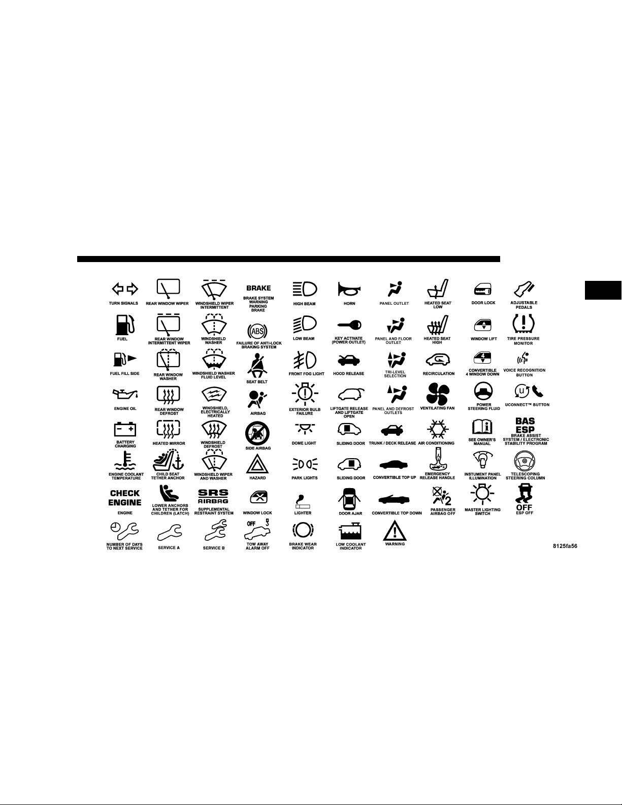
Consult the following table for a description of the
symbols that may be used on your vehicle or throughout
this owner’s manual:
Page 5
INTRODUCTION 5
1
Page 6
6 INTRODUCTION
WARNINGS AND CAUTIONS
This manual contains WARNINGS against operating
procedures which could result in an accident or bodily
injury. It also contains CAUTIONS against procedures
which could result in damage to your vehicle. If you do
not read this entire manual you may miss important
information. Observe all Warnings and Cautions.
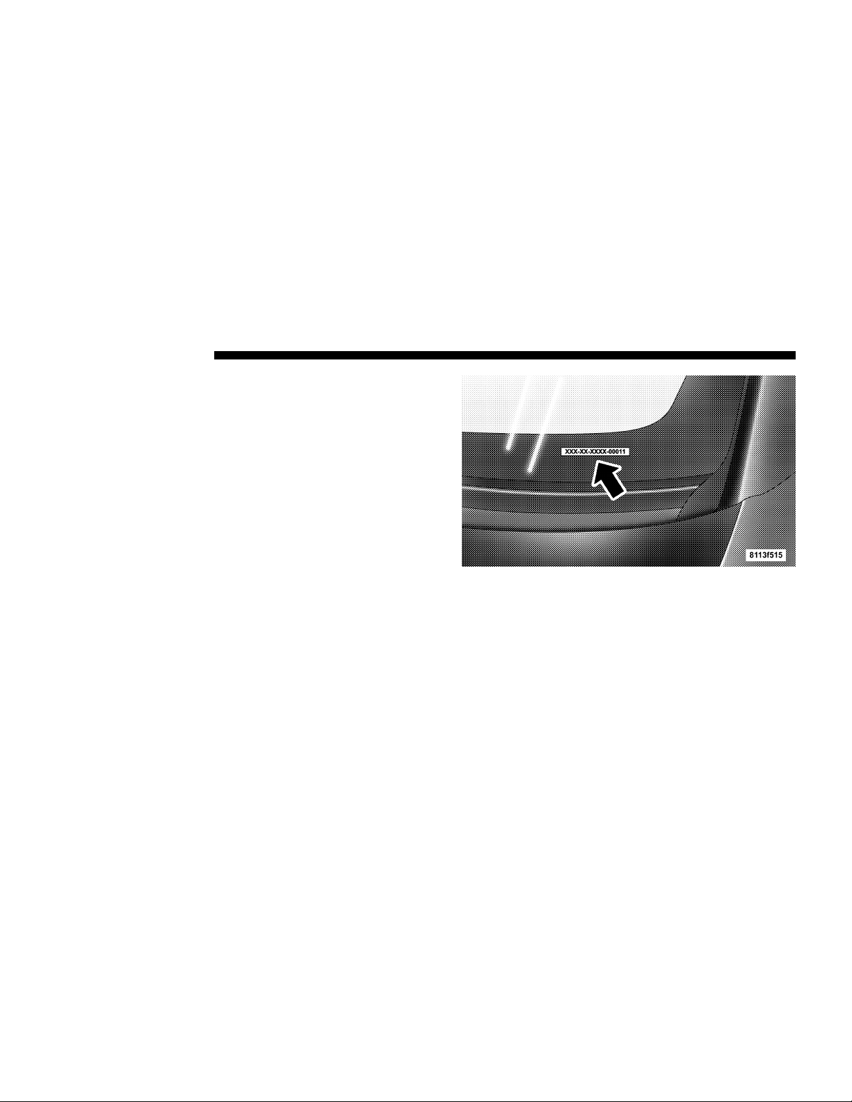
VEHICLE IDENTIFICATION NUMBER
The vehicle identification number (VIN) is located beneath the left front corner of the instrument panel, visible
through the windshield. This number also appears on the
Automobile Information Disclosure Label affixed to a
window on your vehicle. Save this label as a convenient
record of your vehicle identification number and optional
equipment.
Page 7

THINGS TO KNOW BEFORE STARTING YOUR VEHICLE
CONTENTS
䡵 A Word About Your Keys
▫ Keys ...............................9
▫ Obtaining Replacement Keys ..............10
▫ Ignition Key Removal ...................10
▫ Key-In-Ignition Reminder ................10
䡵 Glove Compartment Lock
䡵 Door Locks
▫ Central Locking Switch ..................12
▫ Automatic Central Locking ...............13
▫ General Notes On The Central Locking
System ..............................13
▫ Emergency Unlocking Feature .............14
...........................11
................. 9
.................11
▫ Start Lockout .........................14
䡵 Remote Keyless Entry
▫ To Unlock The Doors ...................14
▫ To Lock The Doors .....................15
▫ Panic Alarm ..........................15
▫ To Use The Panic Alarm .................16
▫ General Information ....................16
▫ Transmitter Battery Service ...............16
䡵 Security Alarm System
▫ Tow-Away Alarm ......................18
䡵 Decklid Internal Emergency
Release - Roadster
....................14
...................17
......................19
2
Page 8

8 THINGS TO KNOW BEFORE STARTING YOUR VEHICLE
䡵 Power Windows
........................20
▫ Power Window Operation With The
Convertible Top Switch (Roadster Only) ......21
䡵 Rear Liftgate/Decklid Release
䡵 Occupant Restraints
.....................21
..............21
▫ Lap/Shoulder Belts .....................22
▫ Seat Belts And Pregnant Women ............27
▫ Seat Belt Extender ......................27
▫ Supplemental Restraint System (SRS) - Airbag . .28
▫ Child Restraint ........................39
䡵 Engine Break-In Recommendations
䡵 Safety Tips
............................46
..........46
▫ Exhaust Gas ..........................46
▫ Safety Checks You Should Make Inside The
Vehicle ..............................47
▫ Periodic Safety Checks You Should Make
Outside The Vehicle ....................47
Page 9
THINGS TO KNOW BEFORE STARTING YOUR VEHICLE 9
A WORD ABOUT YOUR KEYS
You can insert the double-sided keys into the locks with
either side up.
The dealer that sold you your new vehicle has the key
code numbers for your vehicle locks. These numbers can
be used to order duplicate keys only from an authorized
dealer. Ask your dealer for these numbers and keep them
in a safe place.
CAUTION!
An unlocked car is an invitation to thieves. Always
remove the key from the ignition and lock all the
doors when leaving the vehicle unattended.
NOTE:
be removed from the ignition when the vehicle is parked.
To avoid discharging the battery, the key must
Keys
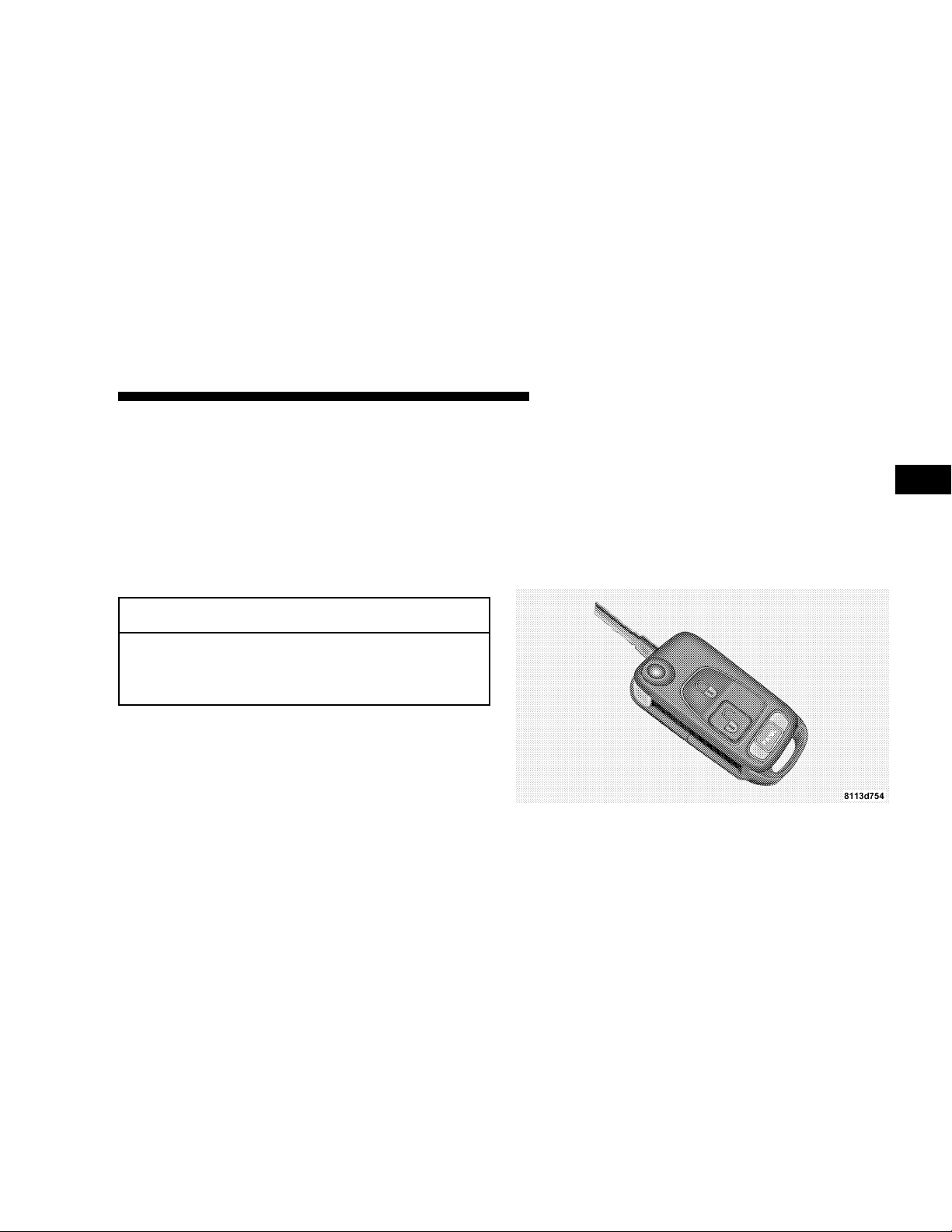
Included with your vehicle are two remote controls with
folding keys. The remote control operates all locks on the
vehicle, including the locking fuel filler door.
To release the key from the folded position, press the
button. The key unfolds from the fob.
The transmitter for the remote control is located in the
key fob.
2
Page 10
10 THINGS TO KNOW BEFORE STARTING YOUR VEHICLE
Obtaining Replacement Keys
Your vehicle is equipped with a theft deterrent locking
system requiring a special key manufacturing process.
For security reasons, replacement keys can only be obtained from your authorized dealer.
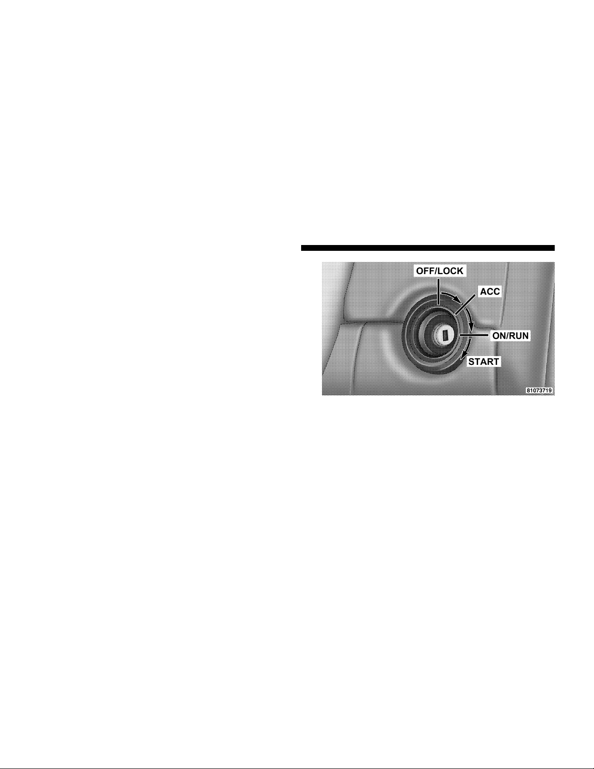
Important!
Removing the key from the steering lock activates the
start lock-out. The engine cannot be started.
Turning the key in the steering lock to the ON/RUN
position deactivates the start lock-out.
NOTE:
In case the engine cannot be started, and START
and ERROR are shown in the odometer display field, the
system is not operational. Contact an authorized dealer.
Ignition Key Removal
Turn the key to the LOCK position and remove the key.
NOTE:
For vehicles with automatic transmissions, if
you try to remove the key before you place the shift lever
in PARK, the key may become trapped temporarily in the
key cylinder. If this occurs, turn the key clockwise
slightly, then remove the key as described.
Key-In-Ignition Reminder
Opening the driver’s door when the key is in the ignition
sounds a signal to remind you to remove the key.
Page 11
THINGS TO KNOW BEFORE STARTING YOUR VEHICLE 11
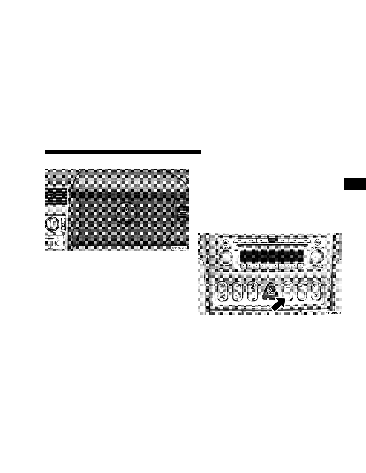
GLOVE COMPARTMENT LOCK
The glove compartment can be locked by turning the key
straight up to the vertical or right position, and then
removing the key.
To unlock the glove compartment, turn the key to the
horizontal or left position, and then remove the key.
DOOR LOCKS
The vehicle doors can be locked when the doors are
closed by either manually pressing the button down at
the top of the door panel, pressing and releasing the
bottom portion of the central locking switch located in
the console, or by pressing and releasing the Lock
transmit button on the key fob. Also, by turning the key
clockwise in the driver’s door, both doors, liftgate/
decklid, fuel filler door, and center console (roadster
only) will lock.
2
Page 12

12 THINGS TO KNOW BEFORE STARTING YOUR VEHICLE
The doors can be unlocked by pulling on the inside door
handle, pressing and releasing the top portion of the
central locking switch located in the console, or by
pressing and releasing the Unlock transmit button on the
key fob. Both doors can also be unlocked by turning the
key counterclockwise in the driver’s door.
NOTE:
If the key in the ignition switch is in the
ON/RUN position, the vehicle cannot be locked or
unlocked with the remote control.
When you lock the vehicle, both door lock buttons
should move down. If either one stays up, the respective
door is not properly closed. You should then unlock the
vehicle, open and reclose the door, and lock the vehicle
again.
Each individual door can be locked with the respective
door lock button - the driver’s door can only be locked
when it is closed. If the vehicle has previously been
locked from the outside, only the door being opened
from the inside will unlock, and the alarm will come on.
The other door, the rear liftgate/decklid, fuel filler door,
and center console (roadster only) will remain locked.
NOTE:
In case of a malfunction in the central locking
system, the doors can be locked and unlocked individually. To lock, turn the key in the driver’s door lock
clockwise, or push down the lock buttons. To unlock,
turn the key in the driver’s door lock counterclockwise,
or pull the inside door handles.
WARNING!
For personal security and safety in the event of an
accident, lock the vehicle doors as you drive and
when you park and leave the vehicle.
Central Locking Switch
The central locking switch is located in the console. The
doors and rear liftgate/decklid can only be locked with
the central locking switch if both doors are closed.
If the vehicle was previously locked with the remote
control or key, the doors and rear liftgate/decklid cannot
be unlocked with the central locking switch. If the vehicle
was previously locked with the central locking switch,
the complete vehicle is unlocked when a door is opened
from the inside.
Page 13

THINGS TO KNOW BEFORE STARTING YOUR VEHICLE 13
NOTE:
only) cannot be locked or unlocked with the central
locking switch.
Automatic Central Locking
The central locking switch also operates the automatic
central locking feature. With the automatic central locking feature activated, the doors and rear liftgate/decklid
are locked at vehicle speeds of approximately 9 mph (15
km/h) or more; however, the fuel filler door remains
unlocked.
To activate this feature, turn the key to the ON/RUN
position and hold the upper portion of the switch for a
minimum of five seconds. To deactivate, turn the key to
the ON/RUN position and hold the lower portion of the
switch for a minimum of five seconds.
NOTE:
locking switch after activating the automatic central
locking feature and neither door is opened, the doors
remain unlocked even at vehicle speeds of approximately
9 mph (15 km/h) or more.
The fuel filler door and center console (roadster
If the doors are unlocked with the central
NOTE:
the ignition and the driver’s door open, the doors will not
lock.
General Notes On the Central Locking System
If the key in the ignition switch is in the ON/RUN
position, the vehicle cannot be locked or unlocked with
the remote control.
If the vehicle cannot be locked or unlocked at any time
with the remote control, it may be necessary to change
the batteries in the remote.
NOTE:
charging during short periods of inactivity, perform the
following:
1. Make sure that the rear liftgate/decklid, hood and
doors are completely closed.
2. Make sure that remote transmitter is operating and
that the battery is good.
3. Make sure that the hood, rear liftgate/decklid and
door switches are in adjustment.
If you attempt to lock the doors with the key in
To help prevent the vehicle battery from dis-
2
Page 14

14 THINGS TO KNOW BEFORE STARTING YOUR VEHICLE
Perform the quick system check which follows: Use
the remote transmitter to set the alarm. If the parking
lamps flash three times, the system is operating properly. If not, there is a problem with a switch or the
system. See your authorized dealer for service.
Emergency Unlocking Feature
In the case of an accident, the doors unlock automatically
a short time after a strong deceleration is detected, such
as in a collision (this is intended to aid rescue and exit).
However, the key must still be in the ignition.
Start Lockout
Removing the key from the ignition switch activates the
start lockout. The engine cannot be started. Turning the
key to the ON/RUN position deactivates the start lockout. If the engine cannot be started, and the messages
START and ERROR are shown in the odometer display
field, the system is not operational. Contact an authorized dealer.
REMOTE KEYLESS ENTRY
This feature allows you to lock or unlock the vehicle from
remote locations using a hand-held transmitter located in
the key fob. You don’t have to point the transmitter at the
vehicle to activate the system. The vehicle doors, rear
liftgate/decklid, fuel filler door, and center console (roadster only) can be locked and unlocked using the remote
control.
To Unlock the Doors:
Press and release the unlock button on the key fob.
NOTE:
If within 40 seconds of unlocking with the key
fob, neither door is opened, the key is not inserted in the
ignition switch, or the central locking switch is not
activated, the vehicle will automatically lock.
Press the Unlock transmit button on the key fob once to
unlock driver’s door, rear liftgate/decklid, fuel filler
door, and center console (roadster only). Press the Unlock
transmit button twice to unlock both doors, rear liftgate/
decklid, fuel filler door, and center console (roadster
only).
Page 15
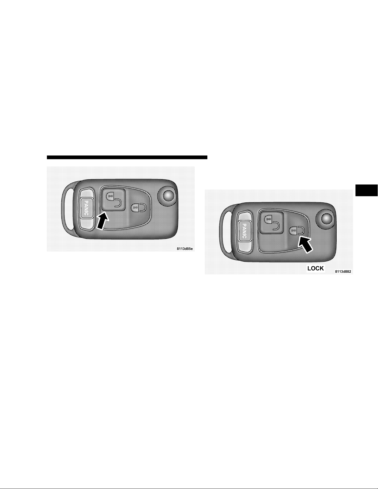
To Lock The Doors:
Press the Lock button on the key fob once. All turn signal
lights blink three times to indicate that the vehicle is
locked. If the turn signal lights do not blink, a door or
rear liftgate/decklid is not closed properly.
The entire vehicle, including the fuel filler door, may be
locked or unlocked by using the key in the driver’s door.
The doors and liftgate/decklid can be locked or unlocked
by pressing the central locking switch located in the
center console.
THINGS TO KNOW BEFORE STARTING YOUR VEHICLE 15
If the vehicle cannot be locked or unlocked by pressing
the transmit button, then it may be necessary to change
the batteries in the remote control.
2
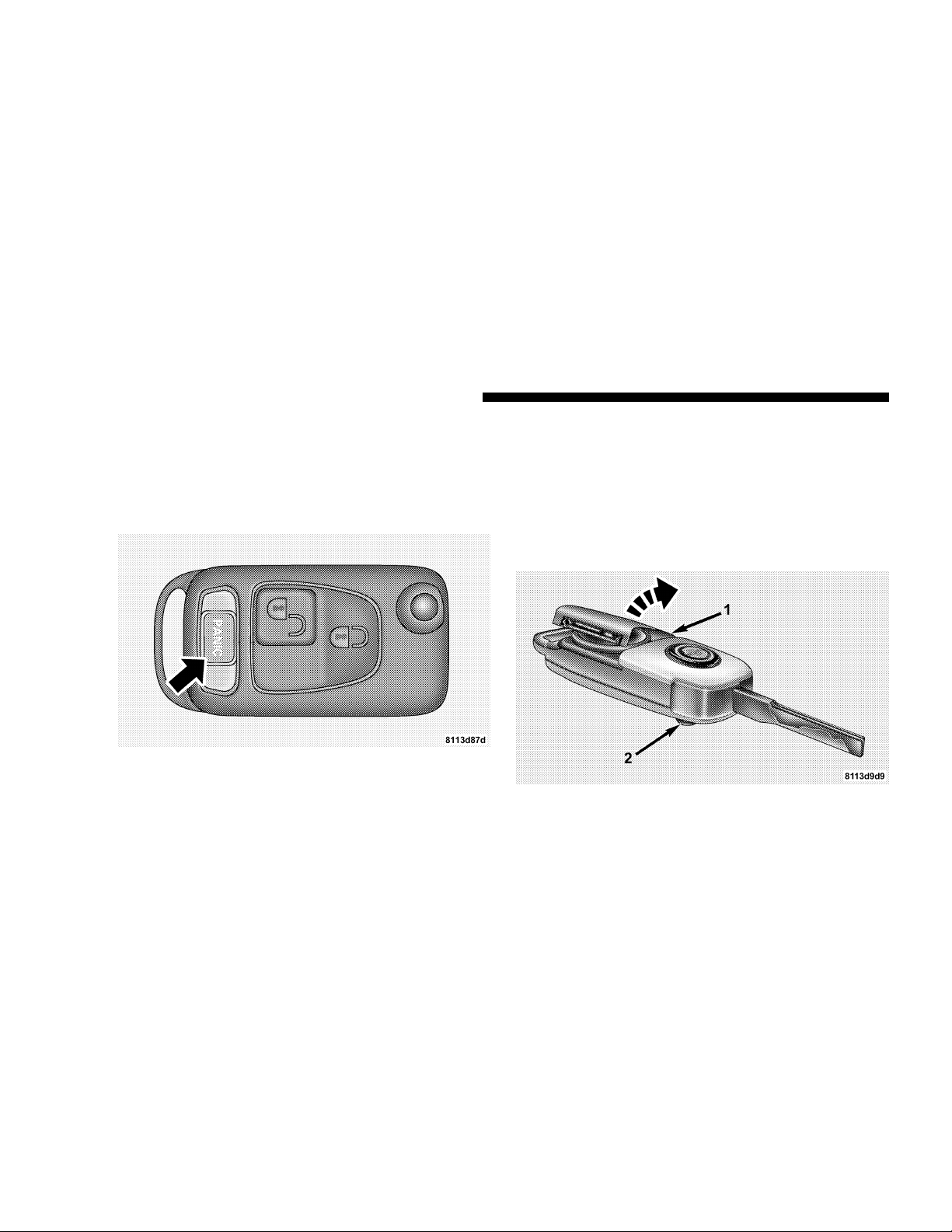
Panic Alarm
The panic alarm unlocks the driver’s door, turns on the
interior lights, flashes the foglights and sounds the horn
for about three minutes or until the alarm is turned off.
The vehicle can be driven while in the Panic mode.
Page 16
16 THINGS TO KNOW BEFORE STARTING YOUR VEHICLE
To Use the Panic Alarm:
Press and hold the Panic button to activate the alarm.
Press and hold the Panic button or unlock the door with
the key to deactivate the alarm. The alarm will also shut
off after three minutes or when vehicle speed reaches 15
mph (24 km/h).
General Information
This transmitter complies with FCC rules part 15. Operation is subject to the following conditions:
1. This device may not cause harmful interference.
2. This device must accept any interference that may be
received, including interference that may cause undesired operation.
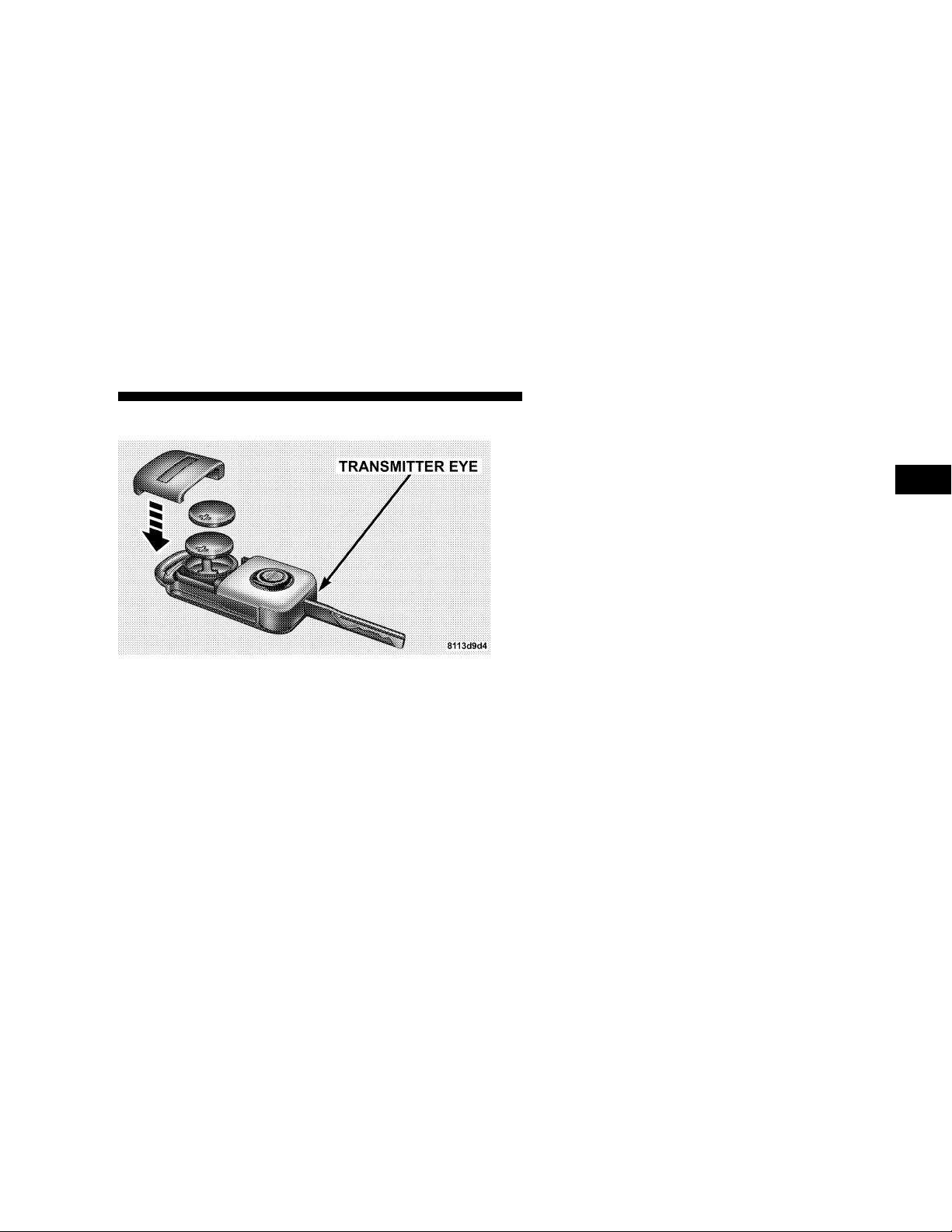
Transmitter Battery Service
The recommended replacement Lithium battery is Panasonic威 CR 2025 or equivalent.
To change the batteries:
•
Press release button (2) on the key fob. The key folds
out.
•
Press the battery cover (1) in the direction of the arrow.
Page 17
THINGS TO KNOW BEFORE STARTING YOUR VEHICLE 17
•
Remove the old batteries.
•
Insert the new batteries in the direction of the arrow
with the positive symbol facing upwards.
•
Replace the battery cover and press on it until you feel
it engage.
NOTE:
The system may have to be resynchronized if the transmitter is without voltage for several minutes. To synchronize, aim the transmitter eye at the vehicle and briefly
press either the Lock or the Unlock button twice. Within
Only replace the batteries in pairs.
approximately 30 seconds, insert the key in the ignition
and turn it to the ON/RUN position. The remote control
should once again be operational.
2
SECURITY ALARM SYSTEM
The system monitors the doors, rear liftgate/decklid,
hood, and ignition for unauthorized operation. The security alarm system is automatically armed or disarmed
with the remote control or any of your vehicle’s keys by
locking or unlocking the vehicle.
The antitheft alarm is armed within approximately 10
seconds after locking the vehicle. A blinking light in the
tow away alarm switch indicates that the alarm is armed.
Once the alarm system has been armed, the exterior
vehicle lights will flash and an alarm will sound when a
door, the rear liftgate/decklid, the hood, or the glove
compartment is opened, or if someone attempts to raise
the vehicle for towing. The alarm will flash the exterior
lamps for approximately three minutes and sound an
audible alarm for 30 seconds. The alarm will stay on even
if the activating element is immediately closed.
Page 18
18 THINGS TO KNOW BEFORE STARTING YOUR VEHICLE
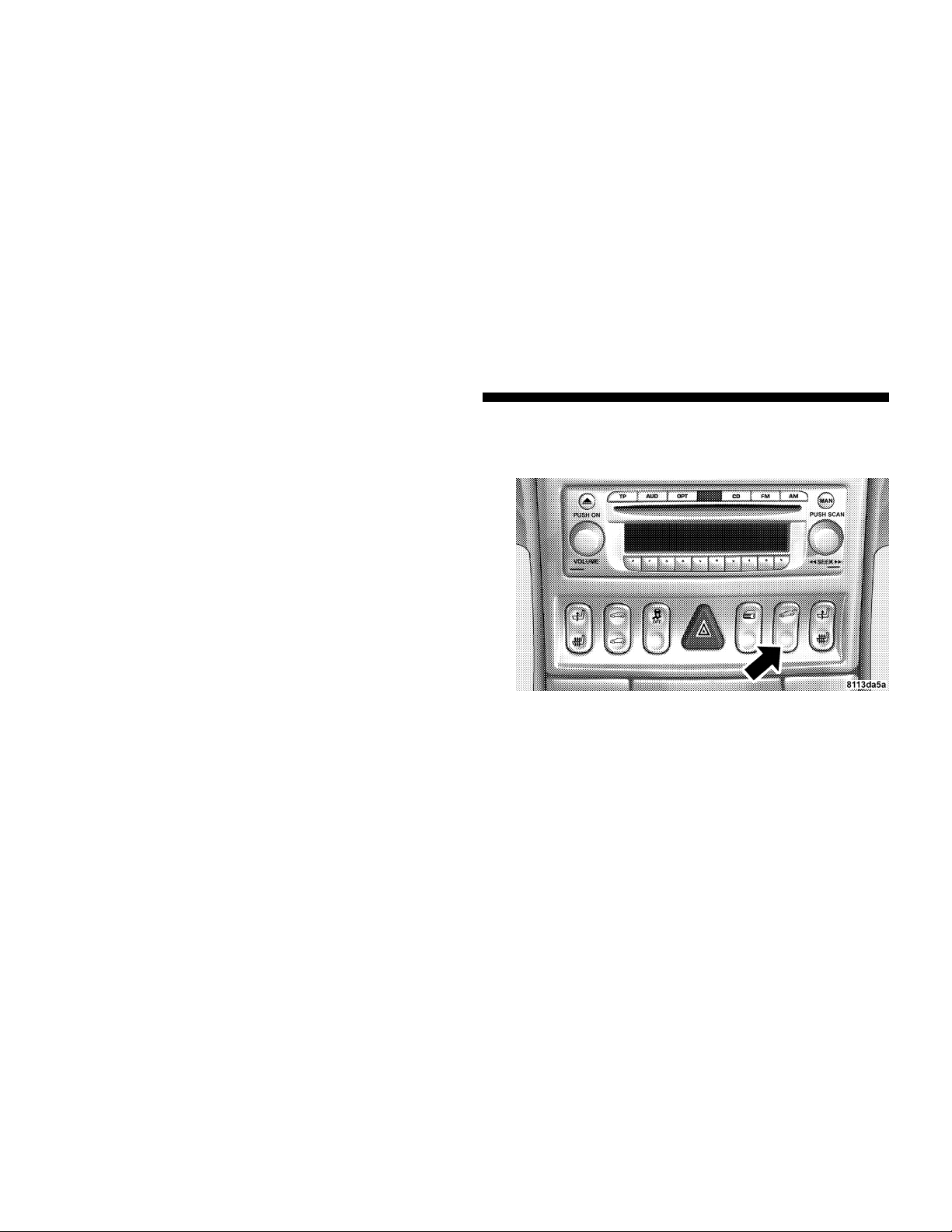
Tow-Away Alarm
The tow-away alarm switch is located on the console. To
deactivate for towing or jacking up the vehicle, press and
release the upper portion of the switch. Press and release
the upper portion to activate it again.
After the alarm system has been armed, the exterior
vehicle lights will flash and an alarm will sound when
someone attempts to raise the vehicle. The alarm will
flash the exterior lamps for approximately three minutes
and sound an audible alarm for 30 seconds. The alarm
will stay on even if the vehicle is immediately lowered.
To cancel the alarm, insert the key into the ignition switch
or press a transmit button on the key fob.
To prevent triggering the tow-away alarm feature when
parking on a surface subject to movement (such as a
ferry), switch off the tow-away alarm. To do so, turn the
key in the ignition switch to the OFF/LOCK or ACC
position, or remove the key from the ignition switch.
Press the tow-away alarm switch and the indicator light
will illuminate briefly. Exit the vehicle, and lock the
vehicle with the key or the remote control.
The tow-away alarm remains switched off until the
vehicle is locked again with the key or the remote control,
at which time it is automatically reactivated.
Page 19
THINGS TO KNOW BEFORE STARTING YOUR VEHICLE 19
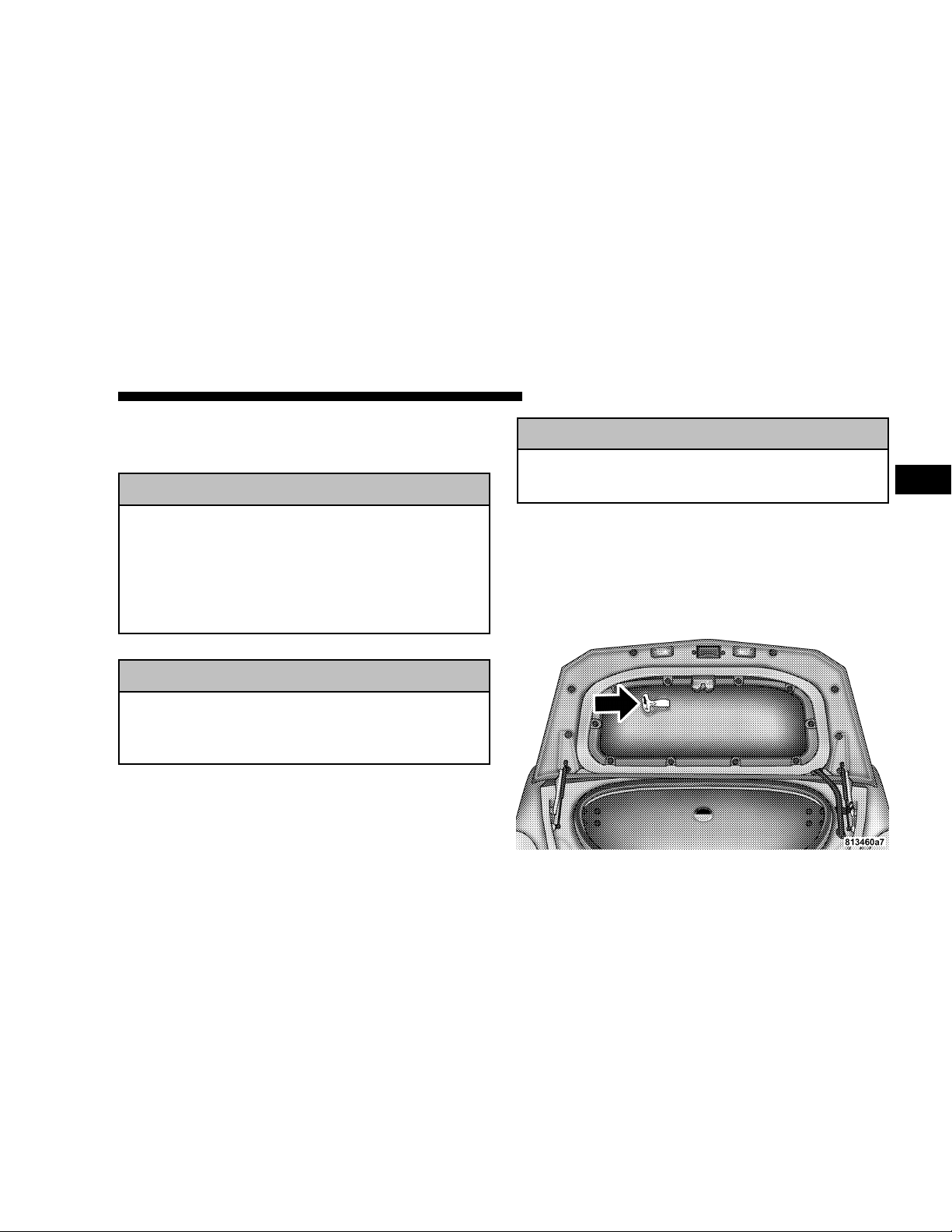
DECKLID INTERNAL EMERGENCY RELEASE ROADSTER
WARNING!
Do not allow children to have access to the trunk by
climbing into the trunk from outside. Always close
the decklid when your vehicle is unattended. Once
in the trunk, young children may not be able to
escape. If trapped in the trunk, children can die from
suffocation or heat stroke.
WARNING!
If the battery voltage drops below the minimum
threshold during the convertible top operation, the
Trunk Internal Emergency Release will not function.
WARNING!
The Trunk Internal Emergency Release will not
function during the convertible top operation.
NOTE:
gency Release lever is built into the decklid latching
mechanism. In the event of an individual being locked
inside the trunk, the decklid can be easily opened by
pulling on the glow-in-the-dark handle attached to the
decklid latching mechanism. See picture.
As a security measure, a Decklid Internal Emer-
2
Page 20
20 THINGS TO KNOW BEFORE STARTING YOUR VEHICLE
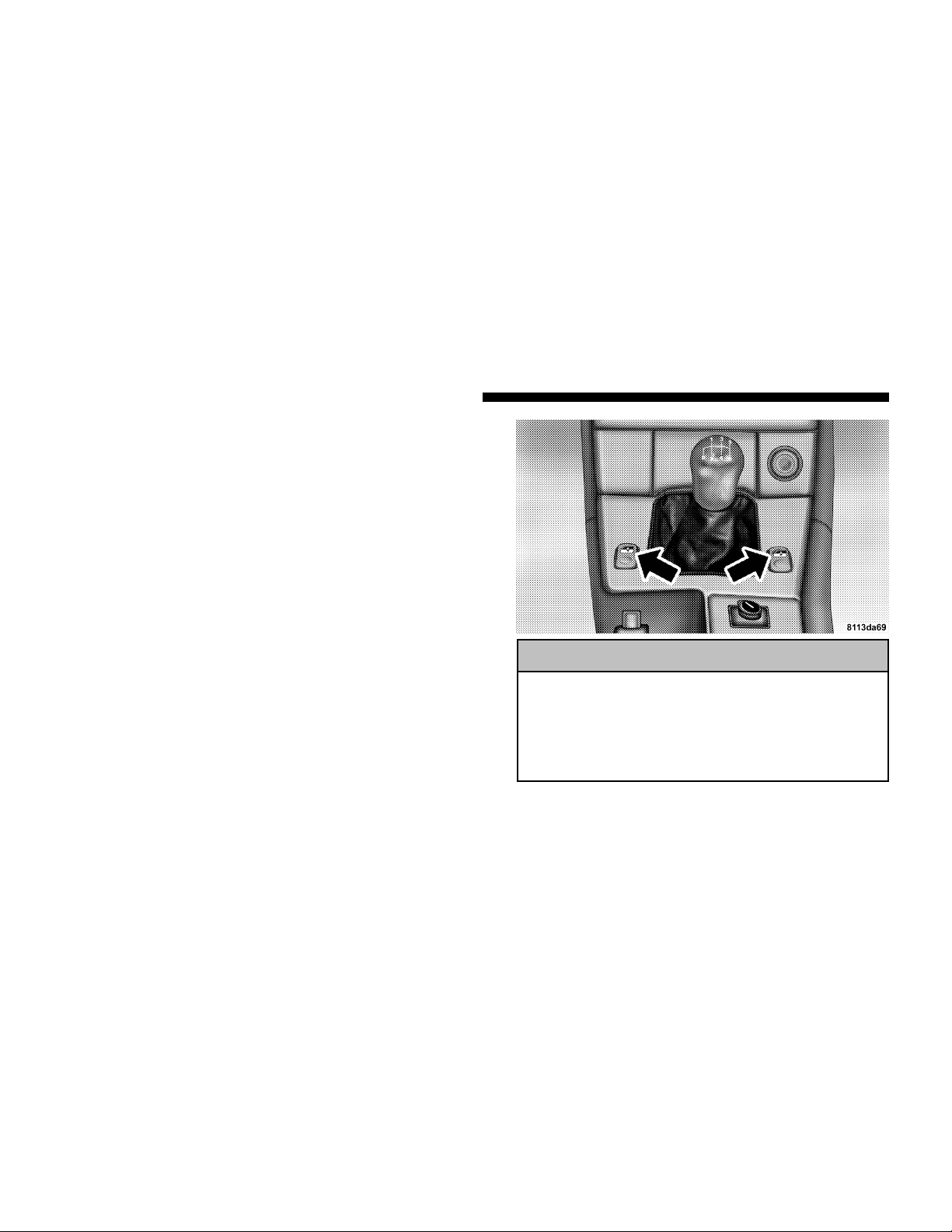
POWER WINDOWS
The power window switches are located in the console.
To operate, turn the key in the ignition switch to the ACC
or ON/RUN position. Press the switch in to the resistance point to open; release the switch when the window
is in the desired position.
For express opening of windows, press the switch past
the resistance point and release; the window lowers to
the fully open position. To interrupt the procedure,
briefly press the switch again and release.
When closing the windows, be sure that there is no
danger of anyone being harmed by the closing procedure.
WARNING!
When leaving the vehicle, always remove the key
from the ignition switch, and lock the vehicle. Do
not leave children unattended in the vehicle, or with
access to an unlocked vehicle. Unsupervised use of
vehicle equipment can cause serious personal injury.
Page 21
THINGS TO KNOW BEFORE STARTING YOUR VEHICLE 21
Power Window Operation With The Convertible
Top Switch (Roadster Only)
The power windows can also be operated by using the
convertible top switch.
To operate, turn the key in the ignition switch to the
ON/RUN position. Press down on the rear of the convertible top switch twice to open the windows.
Press down on the front of the convertible top switch
twice to close the windows.
REAR LIFTGATE/DECKLID RELEASE
You can open the rear liftgate/decklid by using the
handle located on the liftgate/decklid just above the rear
license plate pocket.
WARNING!
Do not allow children to have access to the rear cargo
area by climbing into the rear cargo area from
outside. Always close the liftgate/decklid when your
vehicle is unattended. Once in the cargo area, young
children may have difficulty leaving the vehicle. If
trapped in the cargo area, children can die from
suffocation or heat stroke.
OCCUPANT RESTRAINTS
Some of the most important safety features in your
vehicle are the restraint systems. These include the lap/
shoulder seat belts for the driver and passenger, emergency tensioning retractors for the seat belts, and front
and side airbags for the driver and passenger. If you will
be carrying children too small for adult-size belts, the
passenger side seat belt also can be used to hold infant
and child restraint systems.
2
Page 22

22 THINGS TO KNOW BEFORE STARTING YOUR VEHICLE
Please pay close attention to the information in this
section. It tells you how to use your restraint system
properly to keep you and your passengers as safe as
possible.
WARNING!
In a collision, you and your passengers can suffer
much greater injuries if you are not properly buckled up. You can strike the interior of your vehicle or
other occupants, or you can be thrown out of the
vehicle. Always be sure you and others in your
vehicle are buckled up properly.
Buckle up even though you are an excellent driver, even
on short trips. Someone on the road may be a poor driver
and cause a collision that includes you. This can happen
far away from home or on your street.
Research has shown that seat belts save lives. They also
can reduce the seriousness of injuries in a collision. Some
of the worst injuries happen when people are thrown
from the vehicle. Seat belts provide protection from that,
and they reduce the risk of injury caused by striking the
inside of the vehicle. Everyone in a motor vehicle needs
to be buckled up all the time.
Lap/Shoulder Belts
Each seating position is equipped with a combined
lap/shoulder belt system.
Page 23
THINGS TO KNOW BEFORE STARTING YOUR VEHICLE 23
The belt webbing retractor will lock only during very
sudden stops or impacts. This feature allows the shoulder
part of the belt to move freely with you under normal
conditions. But, in a collision, the belt will lock and
reduce the risk of your striking the inside of the vehicle or
being thrown out. The seat belts are also equipped with
emergency tensioning retractors. These tensioning retractors are located in each belt’s inertia reel and become
operationally ready with the key in the ignition switch
turned to the ACC or ON/RUN positions. The emergency tensioning retractors are designed to activate during frontal and rear impacts. They remove slack from the
belts in such a way that the seat belts fit more snugly
against the body, restricting its forward movement as
much as possible.
In cases of other frontal impacts, rollovers, certain side
impacts, rear collisions or other accidents without sufficient frontal or rear impact forces, the emergency tensioning retractors will not be activated. The driver and
passenger will then be protected by the fastened seat
belts and inertia reel in the usual manner.
WARNING!
•
Wearing a seat belt incorrectly is dangerous. Seat
belts are designed to go around the large bones of
your body. These are the strongest parts of your
body and can take the forces of a collision the
best. Wearing your belt in the wrong place could
make your injuries in a collision much worse. You
might suffer internal injuries, or you could even
slide out of part of the belt. Follow these instructions to wear your seat belt safely and to keep
your passengers safe, too.
•
Two people should never be belted into a single
seat belt. People belted together can crash into one
another in an accident, hurting one another badly.
Never use a lap/shoulder belt or a lap belt for
more than one person, no matter what their size.
2
Page 24
24 THINGS TO KNOW BEFORE STARTING YOUR VEHICLE
Lap/Shoulder Belt Operating Instructions
1. Enter the vehicle and close the door. Sit back and
adjust the seat.
2. The seat belt latch plate is above the back of your seat.
Grasp the latch plate and pull out the belt. Slide the latch
plate up the webbing as far as necessary to make the belt
go around your lap.
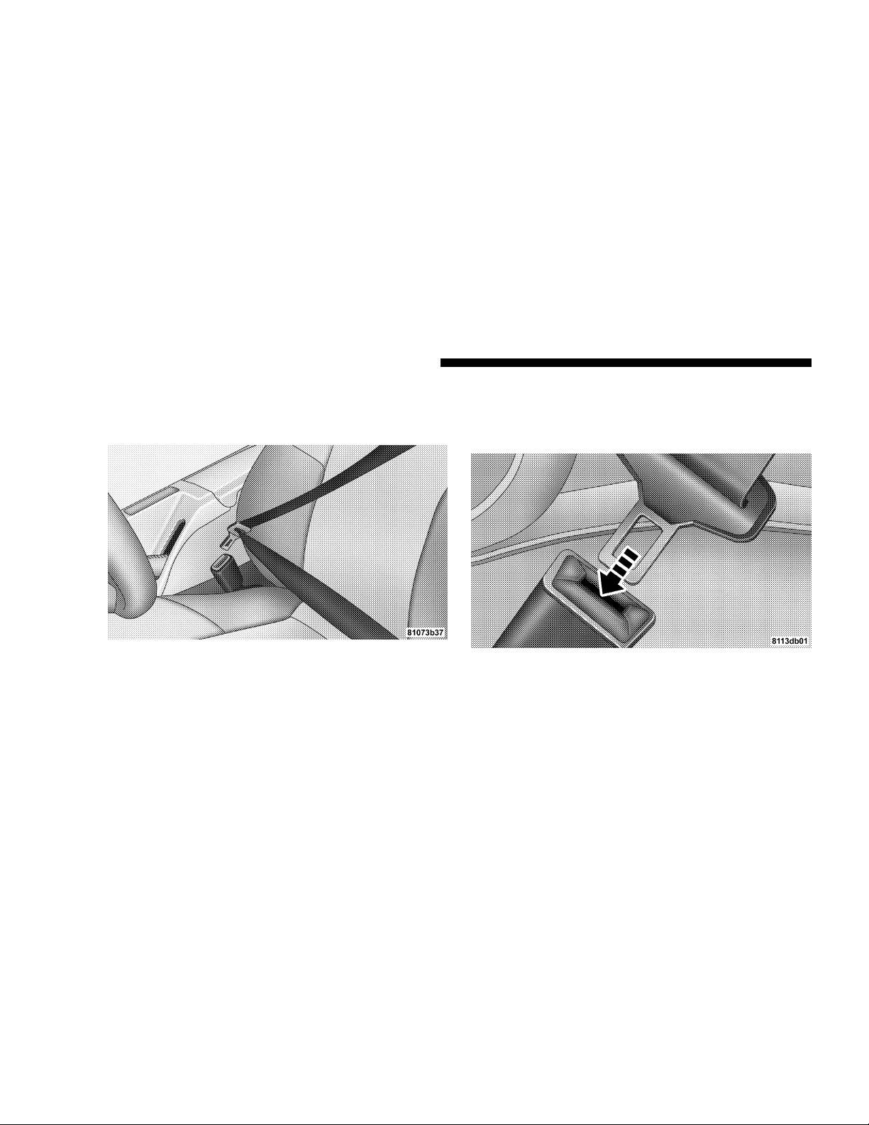
3. When the belt is long enough to fit, insert the latch
plate into the buckle until you hear a “click.”
Page 25
THINGS TO KNOW BEFORE STARTING YOUR VEHICLE 25
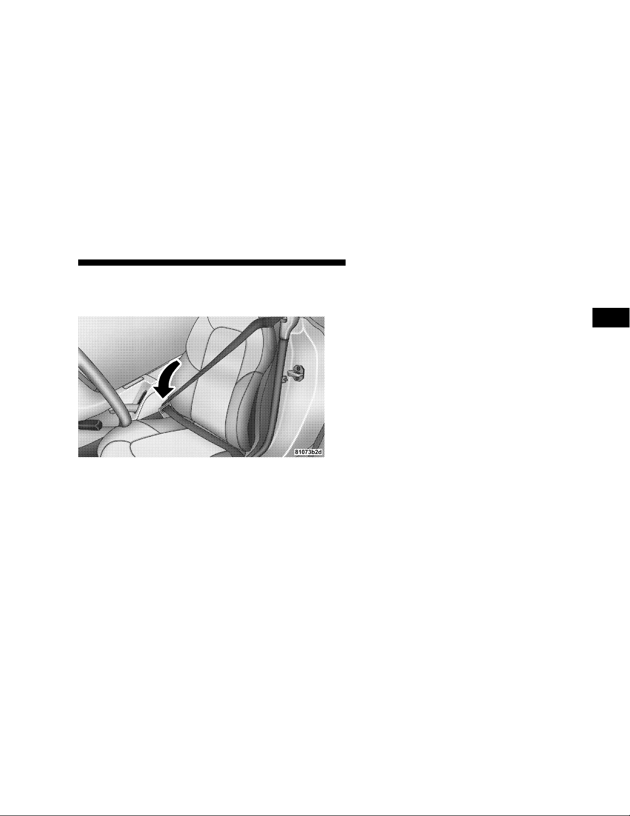
4. Position the lap belt across your thighs, below your
abdomen. To remove slack in the lap belt portion, pull up
a little on the shoulder belt, as shown.
5. To loosen the lap belt if it is too tight, tilt the latch plate
away from you and pull on the lap belt. Remember that
a snug belt reduces the risk of sliding under the belt in a
collision.
6. Position the shoulder belt on your chest so that it is
comfortable and not resting on your neck. The retractor
will withdraw any slack in the belt.
7. To release the belt, push the red button on the buckle.
The belt will automatically retract to its stowed position.
If necessary, slide the latch plate down the webbing to
allow it to retract fully.
2
Page 26

26 THINGS TO KNOW BEFORE STARTING YOUR VEHICLE
WARNING!
•
A belt that is buckled into the wrong buckle will
not protect you properly. The lap portion could
ride too high on your body, possibly causing
internal injuries. Always buckle your belt into the
buckle nearest you.
•
A belt that is too loose will not protect you as well.
In a sudden stop you could move too far forward,
increasing the possibility of injury. Wear your seat
belt snugly.
•
A belt that is worn under your arm is very
dangerous. Your body could strike the inside
surfaces of the vehicle in a collision, increasing
head and neck injury. A belt worn under the arm
can cause internal injuries. Ribs aren’t as strong as
shoulder bones. Wear the belt over your shoulder
so that your strongest bones will take the force in
a collision.
•
A shoulder belt placed behind you will not protect you from injury during a collision. You are
more likely to hit your head in a collision if you
do not wear your shoulder belt. The lap and
shoulder belt are meant to be used together.
WARNING!
•
A lap belt worn too high can increase the risk of
internal injury in a collision. The belt forces won’t
be at the strong hip and pelvic bones, but across
your abdomen. Always wear the lap belt as low as
possible and keep it snug.
•
A twisted belt can’t do its job as well. In a
collision it could even cut into you. Be sure the
belt is straight. If you can’t straighten a belt in
your vehicle, take it to an authorized dealer and
have it fixed.
WARNING!
Seat belt systems must always be replaced after an
impact severe enough to fire the emergency locking
retractors. If there is any question about the condition of your seat belt system, take the vehicle to an
authorized dealer for an inspection.
Page 27
THINGS TO KNOW BEFORE STARTING YOUR VEHICLE 27
WARNING!
A frayed or torn belt could rip apart in a collision
and leave you with no protection. Inspect the belt
system periodically, checking for cuts, frays, or loose
parts. Damaged parts must be replaced immediately.
Do not disassemble or modify the system. Seat belt
assemblies must be replaced after an accident if they
have been damaged (bent retractor, torn webbing,
etc.)
Seat Belts and Pregnant Women
We recommend that pregnant women use the seat belts
throughout their pregnancy. Keeping the mother safe is
the best way to keep the baby safe.
Pregnant women should wear the lap part of the belt
across the thighs and as snug across the hips as possible.
Keep the belt low so that it does not come across the
abdomen. That way the strong bones of the hips will take
the force if there is a collision.
Seat Belt Extender
If a seat belt is too short even when fully extended, an
authorized dealer can provide you with a seat belt
extender. This extender should be used only if the
existing belt is not long enough. When it is not required,
remove the extender and store it.
WARNING!
Using a seat belt extender when not needed can
increase the risk of injury in a collision. Only use the
extender when the lap belt is not long enough when
it is worn low and snug, and in the recommended
seating positions. Remove and store the extender
when not needed.
2
Page 28
28 THINGS TO KNOW BEFORE STARTING YOUR VEHICLE
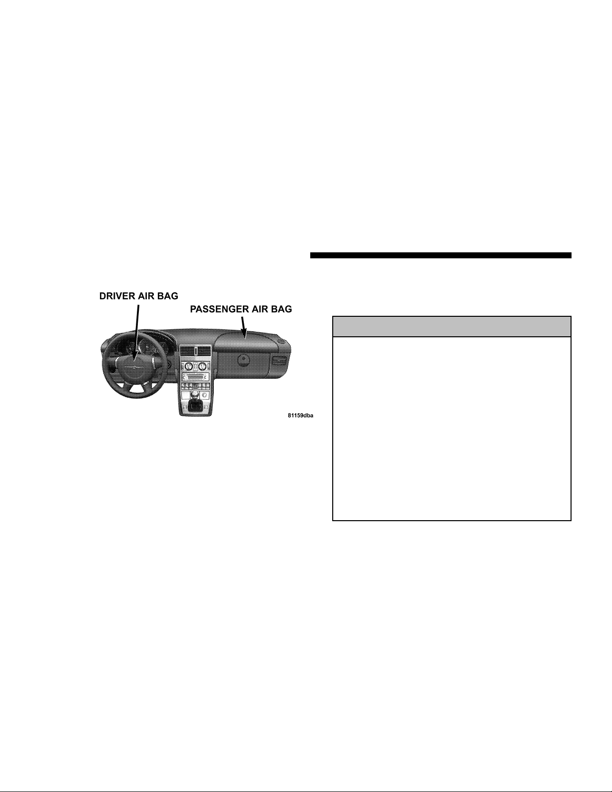
Supplemental Restraint System (SRS) - Airbag
This vehicle has airbags for the driver and passenger as a
supplement to the seat belt restraint systems. The driver’s
airbag is mounted in the steering wheel. The passenger
frontal airbag is mounted in the instrument panel, under
a cover marked SRS/AIRBAG.
These airbags inflate in higher speed frontal impacts.
They work with the instrument panel knee bolster and
the seat belts to provide improved protection for the
driver and passenger.
The vehicle is also equipped with side airbags, located in
the driver and passenger doors. Side airbags also work
with seat belts to improve occupant protection.
WARNING!
•
Do not put anything on or around the front airbag
covers or attempt to manually open them. You
may damage the airbags and you could be injured
because the airbags are not there to protect you.
These protective covers are designed to open only
when the airbags are inflated.
•
Do not place objects between you and the side
airbags; the performance could be adversely affected and/or objects could be pushed into you,
causing serious injury.
•
Do not attach cup holders or any other objects on
or around the door. The inflating side airbag
could drive objects into occupants, causing serious injury.
Page 29

THINGS TO KNOW BEFORE STARTING YOUR VEHICLE 29
The seat belts are designed to protect you in many types
of collisions. The front airbags deploy only in moderate
to severe front collisions. In certain types of collisions,
both the front and side airbags may be triggered. But
even in collisions where the airbags work, you need the
seat belts to keep you in the right position for the airbags
to protect you properly.
Here are some simple steps you can take to minimize
the risk of harm from a deploying airbag.
1. Infants in rear-facing child safety seats should NEVER
ride in the front seat of a vehicle with a passenger frontal
airbag unless the airbag is shut OFF. See “Passenger
Airbag On/Off Switch” and “To Shut Off the Passenger
Airbag.” The rear-facing seat places them too close to the
passenger air bag in the event of a crash. An airbag
deployment can cause severe injury or death to infants in
this position.
Children that are not big enough to properly wear the
vehicle seat belt (see section on “Child Restraint”) should
be secured in child safety seats or booster seats that are
appropriate for the child’s age, height, and weight.
Older children who do not use child safety seats or
booster seats should ride properly buckled. Never allow
children to place the shoulder belt behind them or under
the arm.
If a child from 1 to 12 years old must ride in the vehicle,
move the seat as far back as possible, shut off the
passenger airbag, and use the proper child restraint. See
the section on “Child Restraint.”
You should read the instructions provided with your
child restraint or belt-positioning booster seat to make
sure that you are using it properly.
2. All occupants should wear their lap and shoulder belts
properly.
3. The driver and passenger seats should be moved back
as far as practical to allow the front airbags room to
inflate.
4. Do not lean against the door, as the side airbags will
inflate forcefully into the space between you and the
door. (See the section on “Side Airbags.”)
2
Page 30

30 THINGS TO KNOW BEFORE STARTING YOUR VEHICLE
WARNING!
•
Relying on the airbags alone could lead to more
severe injuries in a collision. The airbags work
with your seat belt to restrain you properly. In
some collisions the airbags won’t deploy at all.
Always wear your seat belts even though you
have airbags.
•
Being too close to the steering wheel or instrument panel during airbag deployment could cause
serious injury.
•
Airbags need room to inflate. Sit back, comfortably extending your arms to reach the steering
wheel or instrument panel.
•
The side airbags also need room to inflate. Do not
lean against the door. Sit upright in the center of
the seat.
Airbag System Components
The airbag system consists of the following:
•
Airbag control module and internal crash sensor
•
AIRBAG readiness light
•
Driver and passenger frontal airbag/inflator units
•
Driver and passenger side airbag/inflator units
•
Passenger airbag On/Off switch and indicator light
•
Unique steering wheel and column
•
Unique instrument panel
•
Interconnecting wiring
•
Knee impact bolster
•
Side impact sensors
Page 31

THINGS TO KNOW BEFORE STARTING YOUR VEHICLE 31
How the Front Airbag System Works
A crash sensor in the occupant compartment deter-
•
mines if a frontal impact is severe enough to require
the airbag. The sensor will not detect side, roll over, or
rear impacts. The sensor is connected to the diagnostic
unit and to the airbag/inflator unit.
•
The Occupant Restraint Controller monitors the readiness of the electronic parts of the system whenever the
ignition switch is in the START or ON/RUN positions.
These include all of the items listed above except the
knee bolster, the instrument panel, and the steering
wheel and column.
•
The Occupant Restraint Controller also turns on the
AIRBAG light in the instrument panel for four seconds
when the ignition is first turned on, then turns the
light off. If it detects a malfunction in any part of the
system, it turns on the light either momentarily or
continuously depending on the condition that is
present at the time.
•
The airbag/inflator units are in the center of the
steering wheel and in the instrument panel. The words
SRS/AIRBAG are embossed on the airbag covers.
WARNING!
Ignoring the AIRBAG light in your instrument panel
could mean you won’t have the airbags to protect
you in a collision. If the light does not come on, stays
on after you start the vehicle, or if it comes on as you
drive, have the airbag system checked right away.
WARNING!
Do not put anything on or around the airbag covers
or attempt to manually open them. You may damage
the airbags and you could be injured because the
airbags are not there to protect you. These protective
covers are designed to open only when the airbags
are inflated.
2
Page 32

32 THINGS TO KNOW BEFORE STARTING YOUR VEHICLE
•
When the crash sensor detects an impact requiring the
airbags, it signals the inflator units. A large quantity of
nontoxic nitrogen gas is generated to inflate the airbags. The airbag covers separate and fold out of the
way as the airbags inflate to their full size. The airbags
then quickly deflate while helping to restrain the
driver and passenger. The airbag gas is vented
through the airbag material towards the instrument
panel. In this way the airbags do not interfere with
your control of the vehicle.
•
The knee impact bolster helps protect the knees and
working with the seat belts, position you for the best
interaction with the airbags.
If a Deployment Occurs
WARNING!
Deployed airbags can’t protect you in another collision. Have the airbags replaced by an authorized
dealer as soon as possible.
Page 33

THINGS TO KNOW BEFORE STARTING YOUR VEHICLE 33
The airbag system is designed to deploy when the impact
sensors detect a moderate-to-severe frontal collision, to
help restrain the driver and passenger, and then to
immediately deflate.
NOTE:
need airbag protection will not activate the system. This
does not mean something is wrong with the airbag
system.
If you do have a collision which deploys the airbags, any
or all of the following may occur:
•
•
A frontal collision that is not severe enough to
The nylon airbag material may sometimes cause abrasions and/or skin reddening to the driver and passenger as the airbags deploy and unfold. The abrasions
are similar to friction rope burns or those you might
get sliding along a carpet or gymnasium floor. They
are not caused by contact with chemicals. They are not
permanent and normally heal quickly. However, if you
haven’t healed significantly within a few days, or if
you have any blistering, see your doctor immediately.
As the airbags deflate, you may see some smoke-like
particles. The particles are a normal by-product of the
process that generates the nontoxic nitrogen gas used
for airbag inflation. These airborne particles may irritate the skin, eyes, nose, or throat. If you have skin or
eye irritation, rinse the area with cool water. For nose
or throat irritation, move to fresh air. If the irritation
continues, see your doctor. If these particles settle on
your clothing, follow the garment manufacturer’s instructions for cleaning.
•
It is not advisable to drive your vehicle after the
airbags have been deployed. If you are involved in
another collision, the airbags will not be in place to
protect you.
How the Side Impact Airbag System Works
The side impact airbags are located in the doors above
•
the armrest.
•
Separate crash sensors in the vehicle determine if a
side impact is severe enough to require the airbag on
the side of the vehicle subjected to an impact. As with
the frontal system, the sensors are connected to the
diagnostic unit and the airbag/inflator units.
2
Page 34

34 THINGS TO KNOW BEFORE STARTING YOUR VEHICLE
•
When a side impact above a predetermined threshold
occurs, the sensors signal the inflator on the impacted
side of the vehicle. A large quantity of nontoxic
nitrogen gas is generated to inflate the airbag. The
door panel opens to allow the airbag to inflate to its
full size.
WARNING!
•
Do not put anything on or around the airbag
covers or attempt to manually open them. You
may damage the airbags and you could be injured
because the airbags are not there to protect you.
These protective covers are designed to open only
when the airbags are inflated.
•
Do not attach cup holders or any other objects on
or around the door. The inflating side airbag
could drive the objects into occupants, causing
serious injury.
Page 35

•
The operational readiness of the side airbag system is
verified by the airbag indicator light in the instrument
cluster when turning the key in the ignition switch to
the ON/RUN position. If no fault is detected, the light
will go out after approximately four seconds. After the
light goes out, the system continues to monitor the
components and circuitry of the airbag system and
will indicate a malfunction by coming on again. If the
light does not come on at all, or if it fails to go out after
the four seconds, or if it comes on thereafter, a malfunction in the system has been detected. See your
authorized dealer for service.
THINGS TO KNOW BEFORE STARTING YOUR VEHICLE 35
WARNING!
•
The door mounted side airbag deploys with considerable force. Being too close to the door panel
during airbag deployment could cause serious
injury or death.
•
All occupants must be in the appropriate restraint
for their size and age, especially children 12 and
under.
•
To help avoid the potential for serious injury and
death should the side airbag be activated, please
follow these guidelines:
1. Occupants, especially children, should never lean
against the door in the area where the side airbag
inflates;
2. Occupants need to sit upright in the center of the
seat to give the side airbag room to inflate;
3. Always use the appropriate restraint for the occupant and ensure it is properly used.
2
Page 36

36 THINGS TO KNOW BEFORE STARTING YOUR VEHICLE
Passenger Front Airbag On/Off Switch
The on/off switch is located at the right end of the
instrument panel and is accessible by opening the passenger door.
The on/off switch is to be used only when the passenger
is:
•
an infant (less than 1 year old),
•
a child, age 1 to 12,
•
an adult with a medical condition which makes passenger airbag inflation (deployment) a greater risk for
the passenger than the risk of hitting the dashboard
(instrument panel) or windshield in a crash.
If the airbag is turned off when there is any other
occupant at that position, the supplemental restraint
provided by the airbag will not be available.
To turn OFF the passenger front airbag, use the on/off
switch located on the instrument panel.
Page 37

THINGS TO KNOW BEFORE STARTING YOUR VEHICLE 37
NOTE:
yellow airbag off light will illuminate.
To Shut Off the Passenger Airbag:
•
When the passenger airbag is turned off, the
Place the ignition key in the on/off switch, turn the
key clockwise, and remove the key from the switch.
This will shut off the passenger front airbag.
•
The air bag will remain off until the switch is turned
back to the ON position.
•
The switch does NOT turn off the side airbag.
2
Page 38

38 THINGS TO KNOW BEFORE STARTING YOUR VEHICLE
To Turn On the Passenger Airbag:
•
Place the ignition key in the on/off switch, turn the
key counterclockwise, and remove the key from the
switch. This will turn on the passenger airbag. The
Passenger Airbag Off light on the console will turn off,
or will not be illuminated when the ignition is turned
to the ON position.
WARNING!
The airbag may malfunction and serious injury
could result if key is left in the airbag shut off
switch. Always remove the key.
Maintaining Your Airbag System
WARNING!
•
Modifications to any part of the airbag system
could cause it to fail when you need it. You could
be injured because the airbag is not there to
protect you. Do not modify the components or
wiring, including adding any kind of badges or
stickers to the airbag covers. Do not modify the
front bumper or vehicle body structure.
•
You need proper knee impact protection in a
collision. Do not mount or locate any aftermarket
equipment on or behind the knee impact bolster.
•
You can be injured if you are too close to either
airbag cover when the airbags inflate. It is dangerous to try to repair any part of the airbag
system yourself. Don’t try to repair the airbag
system. Be sure to tell anyone who works on your
vehicle that it has airbags.
Page 39

THINGS TO KNOW BEFORE STARTING YOUR VEHICLE 39
Airbag Light
You will want to have the airbags ready for
your protection in case of a collision. While the
airbag Supplemental Restraint System (SRS) is
designed to be maintenance free, if any of the
following occurs, have an authorized dealer service the
system immediately.
•
The AIRBAG light does not come on or flickers during
the four seconds when the ignition switch is first
turned on.
•
The light remains on or flickers after the four second
interval.
•
The light flickers or comes on and remains on while
driving.
Child Restraint
Everyone in your vehicle needs to be buckled up all the
time, babies and children, too. Every state in the United
States and all Canadian provinces require that small
children ride in proper restraint systems. This is the law,
and you can be prosecuted for ignoring it.
WARNING!
In a collision, an unrestrained child, even a tiny
baby, can become a missile inside the vehicle. The
force required to hold even an infant on your lap
could become so great that you could not hold the
child, no matter how strong you are. The child and
others could be badly injured. Any child riding in
your vehicle should be in a proper restraint for the
child’s size.
Infants and Child Restraints
There are different sizes and types of restraints for
children from newborn size to the child almost large
enough for an adult safety belt. Always check the child
seat Owner’s Manual to ensure you have the right seat
for your child. Use the restraint that is correct for your
child:
2
Page 40

40 THINGS TO KNOW BEFORE STARTING YOUR VEHICLE
•
Safety experts recommend that children ride
rearward-facing in the vehicle until they are at least
one year old and weigh at least 9 kg (20 lbs.). Two
types of child restraints can be used rearward-facing:
infant carriers and “convertible” child seats.
•
The infant carrier is only used rearward-facing in the
vehicle. It is recommended for children who weigh up
to about 20 lbs. (9 kg). “Convertible” child seats can be
used either rearward-facing or forward-facing in the
vehicle. Convertible child seats often have a higher
weight limit in the rearward-facing direction than
infant carriers do, so they can be used rearward-facing
by children who weigh more than 20 lbs. (9 kg) but are
less than one year old. Both types of child restraints are
held in the vehicle by the lap/shoulder belt or the
LATCH child restraint anchorage system. (See the
LATCH - Child Seat Anchorage System section.)
•
Rearward-facing child seats must NEVER be used in
the front seat of a vehicle with the front passenger
airbag unless the airbag is turned off. An airbag
deployment could cause severe injury or death to
infants in this position.
WARNING!
•
A rearward facing infant restraint must not be
used unless the passenger airbag has been shut
off. A rearward facing infant restraint may be
struck by a deploying passenger airbag which
may cause severe or fatal injury to the infant.
•
Improper installation can lead to failure of a child
restraint. It could come loose in a collision. The
child could be badly injured or killed. Follow the
manufacturer’s directions exactly when installing
a child restraint.
Here are some tips on getting the most out of your child
restraint:
•
Before buying any restraint system, make sure that it
has a label certifying that it meets all applicable Safety
Standards. We also recommend that you make sure
that you can install the child restraint in the vehicle
where you will use it before you buy it.
Page 41

THINGS TO KNOW BEFORE STARTING YOUR VEHICLE 41
•
The restraint must be appropriate for your child’s
weight and height. Check the label on the restraint for
weight and height limits.
•
Carefully follow the instructions that come with the
restraint. If you install the restraint improperly, it may
not work when you need it.
•
Buckle the child into the seat according to the seat
manufacturer’s directions.
•
When your child restraint is not in use, secure it in the
vehicle with the seat belt or remove it from the vehicle.
Do not leave it loose in the vehicle. In a sudden stop or
collision, it could strike the occupants and cause
serious personal injury.
NOTE:
www.seatcheck.org or call 1–866–SEATCHECK.
Older Children and Child Restraints
Children who weigh more than 20 lbs. (9 kg) and who are
older than one year can ride forward-facing in the
vehicle. Forward-facing child seats and convertible child
seats used in the forward-facing direction are for children
who weigh 20 to 40 lbs. (9 to 18 kg) and who are older
For additional information refer to
than one year. These child seats are also held in the
vehicle by the lap/shoulder belt or the LATCH child
restraint anchorage system. (See LATCH - Child Seat
Anchorage System section.)
The belt-positioning booster seat is for children weighing
more than 40 lbs. (18 kg), but who are still too small to fit
the vehicle’s seat belts properly. If the child cannot sit
with knees bent over the vehicle’s seat cushion while the
child’s back is against the seat back, they should use a
belt-positioning booster seat. The child and beltpositioning booster seat are held in the vehicle by the
lap/shoulder belt.
Children Too Large For Booster Seats
Children who are large enough to wear the shoulder belt
comfortably, and whose legs are long enough to bend
over the front of the seat when their back is against the
seat back, should use the lap/shoulder belt.
•
Make sure that the child is upright in the seat.
•
The lap portion should be low on the hips and as snug
as possible.
2
Page 42

42 THINGS TO KNOW BEFORE STARTING YOUR VEHICLE
•
Check belt fit periodically. A child’s squirming or
slouching can move the belt out of position.
•
If the shoulder belt contacts the face or neck, move the
child closer to the center of the vehicle. Never allow a
child to put the shoulder belt under an arm or behind
their back.
LATCH - Child Seat Anchorage System (Lower
Anchors and Tether for Children)
Your vehicle’s passenger seat is equipped with the child
restraint anchorage system called LATCH. The LATCH
system provides for the installation of the child restraint
without using the vehicle’s belts, instead securing the
child restraint using lower anchorages and upper tether
straps from the child restraint to the vehicle structure.
LATCH-compatible child restraints are now available.
Installing the LATCH-Compatible Child Restraint
System
We urge that you carefully follow the directions of the
manufacturer when installing your child restraint. These
are general instructions, and not all child restraint systems will be installed exactly as described here. Again,
carefully follow the installation instructions that were
provided with the child restraint system.
The passenger seat lower anchorages are round bars,
located at the rear of the seat cushion where it meets the
seat back, and are just visible when you lean in to install
the child restraint. You will easily feel them if you run
your finger along the intersection of the seat back and
seat cushion surfaces.
Page 43

THINGS TO KNOW BEFORE STARTING YOUR VEHICLE 43
The passenger seat tether anchorage is located on the
back of the seat cushion frame. It is visible by moving the
passenger seat forward in the vehicle.
Many, but not all LATCH-Compatible child restraint
systems will be equipped with separate straps on each
side, with each having a hook or connector for attachment to the lower anchorage and a means of adjusting
the tension in the strap. Forward-facing toddler restraints
and some rear-facing infant restraints will also be
equipped with a tether strap, a hook for attachment to the
tether strap anchorage and a means of adjusting the
tension of the strap.
You will first loosen the adjusters on the lower straps and
on the tether strap so that you can more easily attach the
hooks or connectors to the vehicle anchorages. Next, you
can attach the tether strap to the anchor by moving the
passenger seat forward. Route the child restraint tether
directly over the top of the seat, through the strap near
the top of the seat back, and attach the hook to the anchor
bar. Recline the seat back and move the passenger seat as
far rearward as possible. Next, attach the lower hooks to
the passenger seat lower anchor bars by pushing aside
the seat cover material. Finally, tighten all three straps as
you push the child restraint rearward and downward
into the seat, removing slack in the straps according to
the child restraint manufacturer’s instructions.
2
Page 44

44 THINGS TO KNOW BEFORE STARTING YOUR VEHICLE
WARNING!
Improper installation of a child restraint to the
LATCH anchorages can lead to failure of an infant or
child restraint. The child could be badly injured or
killed. Follow the manufacturer’s directions exactly
when installing an infant or child restraint.
Installing Child Restraints Using the Vehicle Seat
Belt
Child restraints can be securely fastened in the passenger
seat using the seat belts. For this purpose, the passenger
seat belt retractor provides two modes of operation normal emergency locking and automatic locking. For
child restraint installation, the retractor switches to automatic locking when the belt is pulled out to the full extent
of its travel. As the belt retracts, the retractor locks to
prevent the belt from being pulled out again. Pulling the
belt snugly over the child restraint toward the retractor
secures the restraint in place. When the belt retracts fully
after child restraint removal, normal (emergency locking)
retractor action is restored. Any seat belt system will
loosen with time, so check the belt occasionally and pull
it tight if necessary.
If your child restraint is equipped with a tether strap,
attach it to the vehicle by first moving the seat back fully
forward. Next, route the child restraint tether directly
over the top of the seat, through the strap near the top of
the seat back, and attach the hook to the anchor bar.
Recline the seat back and move the passenger seat as far
rearward as possible. Remove slack in the tether strap as
you push the child restraint downward and rearward,
following the child restraint manufacturer’s instructions.
Child Restraint Tether Anchor - General
Information
Child restraints having tether straps and hooks for connection to tether anchors have been available for some
time. In fact, many child restraint manufacturers will
provide add-on tether strap kits for certain of their older
products. There is a tether strap anchor behind the
passenger seat.
Page 45

THINGS TO KNOW BEFORE STARTING YOUR VEHICLE 45
To attach the tether strap to the anchor, move the
seatback fully forward. Pass the child restraint tether
hook over the top of the seat, through the strap near the
top of the seat back, and attach it to the anchor bar behind
the passenger seat, below the seatback. After securing the
tether hook to the bar, recline the seatback fully rearward
and move the seat to its most rearward position.
Install the child restraint and return the seatback to an
upright position. Remove slack from the tether strap
according to the child restraint manufacturer’s directions.
2
WARNING!
An incorrectly anchored tether strap could lead to
increased head motion and possible injury to the
child. Use only the anchor position directly behind
the child seat to secure a child restraint top tether
strap.
Transporting Pets
Deploying airbags could harm your pet. An unrestrained
pet will be thrown about and possibly injured, or injure a
passenger during panic braking or in a collision.
Pets should be restrained in pet harnesses or pet carriers
that are secured by seat belts.
Page 46

46 THINGS TO KNOW BEFORE STARTING YOUR VEHICLE
ENGINE BREAK-IN RECOMMENDATIONS
The engine in your new Crossfire does not require a long
break-in period. Following these few simple guidelines is
all that is necessary for a good break-in.
•
Drive your vehicle at moderate vehicle and engine
speeds during the first 1,000 miles (1,600 km).
•
Do not make any full throttle starts and avoid full
throttle acceleration.
•
Use the proper transmission gear for your speed
range.
•
Avoid excessive idling.
•
Check the engine oil level at every fuel fill.
NOTE:
A new engine may consume some oil during the
first few thousand miles of operation. This should be
considered as a normal part of the break-in and not an
indication of a problem.
SAFETY TIPS
Exhaust Gas
WARNING!
Exhaust gases can injure or kill. They contain carbon
monoxide (CO) which is colorless and odorless.
Breathing it can make you unconscious and can
eventually poison you. To avoid breathing (CO)
follow the safety tips below.
•
Do not run the engine in a closed garage or in confined
areas any longer than needed to move your vehicle in
or out of the area.
•
If it is necessary to sit in a parked vehicle with the
engine running, adjust your heating or cooling controls to force outside air into the vehicle. Set the blower
at high speed.
•
To avoid drawing exhaust gases into the vehicle, close
the rear liftgate/decklid while driving. However, if for
some reason it must remain open, close all windows.
Adjust the heating or cooling system to force outside
air into the vehicle. Set the blower at high speed.
Page 47

THINGS TO KNOW BEFORE STARTING YOUR VEHICLE 47
Safety Checks You Should Make Inside the Vehicle
Seat Belts
Inspect the belt system periodically, checking for cuts,
frays and loose parts. Damaged parts must be replaced
immediately. Do not disassemble or modify the system.
Seat belt assemblies must be replaced after an accident if
they have been damaged (bent retractor, torn webbing,
etc.). If there is any question regarding belt or retractor
condition, see your authorized dealer.
Airbag Light
The light should come on and remain on for
four seconds as a bulb check when the ignition
switch is first turned ON. If the bulb is not lit
during starting, have it replaced. If the light
stays on or comes on while driving, have the system
checked by an authorized dealer.
Defrosters
Check operation by pressing the A/C control button,
selecting the defrost mode and placing the blower control
on high speed. You should be able to feel the air directed
against the windshield.
Periodic Safety Checks You Should Make Outside
the Vehicle
Tires
Examine tires for excessive tread wear or uneven wear
patterns. Check for stones, nails, glass, or other objects
lodged in the tread. Inspect for tread cuts or sidewall
cracks. Check wheel nuts for tightness and tires for
proper pressure.
Lights
Have someone observe the operation of exterior lights
while you work the controls. Check turn signal and high
beam indicator lights on the instrument panel.
Fluid Leaks
Check area under vehicle after overnight parking for fuel,
water, oil, or other fluid leaks. Also, if gasoline fumes are
present, the cause should be corrected immediately.
NOTE:
of water to form under the vehicle.
Use of the air conditioning may cause puddles
2
Page 48

Page 49

UNDERSTANDING THE FEATURES OF YOUR VEHICLE
CONTENTS
䡵 Convertible Top Operation
................52
䡵 Mirrors
..............................66
3
▫ To Lower The Top ......................53
▫ To Raise The Top ......................57
▫ Convertible Top Lamp And Audible Signal
Chart ...............................60
䡵 Console Features
▫ Storage Compartments ..................62
▫ Ashtray .............................63
▫ Coin Holder ..........................64
▫ Power Outlet/Cigar Lighter ...............64
▫ Glove Compartment ....................65
䡵 Cupholder
.......................61
............................65
▫ Inside Day/Night Mirror .................66
▫ Exterior Mirrors Folding Feature ...........66
▫ Heated Remote Control Mirrors ............66
▫ Outside Mirrors .......................66
▫ Power Remote Control Outside Mirrors ......67
▫ Vanity Mirrors ........................68
䡵 Seats
................................68
▫ Driver Eight-Way Power Seat ..............68
▫ Passenger Four-Way Power Seat ............69
▫ Heated Seats .........................70
Page 50

50 UNDERSTANDING THE FEATURES OF YOUR VEHICLE
䡵 To Open And Close The Hood
䡵 Interior Lights
.........................71
.............70
▫ Front Map/Reading Lights ...............72
▫ Battery Saver Feature ...................72
▫ Instrument Panel Lighting ................72
▫ Night Security Illumination ...............72
䡵 Exterior Lights
.........................73
▫ Headlights And Parking Lights ............73
▫ Daytime Running Lights (Where Applicable) . . .73
▫ Fog Lights ...........................74
▫ Standing Lights .......................74
䡵 Multifunction Control Lever
...............75
▫ Turn Signals ..........................75
▫ Headlight Dimmer Switch ................76
▫ Passing Light .........................76
▫ Windshield Wipers And Washer ............77
▫ Mist Function .........................78
䡵 Telescoping Steering Column
䡵 Tire Pressure Monitor System
䡵 Rear Spoiler
...........................82
䡵 Brake Assist System (BAS)
䡵 Electronic Stability Program (ESP)
..............79
..............80
................85
...........86
▫ Synchronizing ESP .....................88
䡵 Electronic Speed Control
..................88
▫ To Vary The Speed Setting ................90
▫ To Deactivate .........................90
▫ To Resume Speed ......................91
▫ Using Speed Control On Hills .............91
䡵 Garage Door Opener
....................92
▫ Programming The Universal Transceiver ......92
▫ Gate Operator/Canadian Programming ......95
▫ Using The Universal Transceiver ...........95
Page 51

UNDERSTANDING THE FEATURES OF YOUR VEHICLE 51
▫ Erasing Universal Transceiver Buttons ........95
▫ Reprogramming a Single Button ............96
▫ Security .............................96
䡵 Umbrella Hook
........................96
3
Page 52

52 UNDERSTANDING THE FEATURES OF YOUR VEHICLE
CONVERTIBLE TOP OPERATION
WARNING!
The convertible top does not provide the structural
protection that a reinforced metal roof does and the
fabric top cannot be expected to prevent the ejection
of the occupants of a vehicle in a collision. Therefore, it is important that all occupants wear their seat
belts at all times when riding in a convertible.
Studies have shown that it is generally safer to
remain inside a vehicle during a collision than to be
ejected from the vehicle.
For safety reasons, the convertible top should only be
opened and closed when the vehicle is standing still. Top
operation is allowed up to a maximum of 9 mph (15
km/h). Above this speed, top operation will cease and an
audible warning will sound. The top operation can be
resumed after the vehicle is below the maximun speed by
pressing the convertible top switch again.
WARNING!
Before operating the switch for the convertible top,
make sure that no persons can be injured by the
moving parts (convertible top frame and tonneau
cover).
Hands must never be placed near the sport bar,
convertible top frame, upper windshield area, shelf
behind sport bar, or convertible top storage compartment while the convertible top is being raised or
lowered. Serious personal injury may occur.
If potential danger exists, release the convertible top
switch. This immediately interrupts the raising or
lowering procedure. You then can operate the convertible top switch to raise or lower the convertible
top away from the danger zone.
Page 53

UNDERSTANDING THE FEATURES OF YOUR VEHICLE 53
CAUTION!
When opening and closing the convertible top, make
sure that:
•
There is sufficient clearance of at least 6 ft. (1.8m)
for the convertible top to move up.
•
Nothing is placed on the tonneau cover.
•
The outside temperature is above 32°F (0°C).
Otherwise the convertible top and other parts of the
vehicle could be damaged.
To Lower The Top:
WARNING!
Top operation can be suspended for a maximum of
10 minutes. Thirty seconds before the end of this
period an audible warning will begin to sound
continuously. At the end of this period, hydraulic
pressure will be released and the top and tonneau
cover will slowly collapse. In order to re-initialize
the top cycle, the tonneau cover must be lowered to
its full open position manually. Hands should be
kept away from moving parts of the top compartment mechanism to avoid injury as hydraulic pressure is reestablished. The hydraulic pressure can be
reestablished by turning the ignition to the ON/RUN
postion and pushing down on the convertible top
switch twice. Refer to Convertible Top Emergency
Operation in the What To Do In Emergencies section
of this manual.
3
Page 54

54 UNDERSTANDING THE FEATURES OF YOUR VEHICLE
CAUTION!
To avoid possible damage to the tonneau cover and
convertible top, do not allow the convertible top to
remain in the suspended position. After approximately 10 minutes in the suspended position, the
hydraulic pressure will be released which will allow
the top and the tonneau cover to lower. The convertible top switch can be pressed to cancel this operation.
CAUTION!
To avoid damage to either the top or the rear window, check the tonneau cover area at the rear of the
vehicle interior to be sure that it is clear of debris or
other items. Do not use the tonneau cover area for
other storage purposes.
CAUTION!
To fully insure that no damage occurs, be sure that
the vehicle is at a complete stop before attempting to
lower or raise the top.
NOTE:
procedure, start the engine and continue operation.
1. Make sure the rear cargo compartment divider is
unfolded and secured in the vertical position.
If the divider is in its stowed position, first unfold the
panels towards the rear of the vehicle. Pull up on the
vertical panel using the center cutout shown, and hook
the pins at the top into the brackets mounted to the cargo
compartment trim on each side near the forward edge of
the decklid opening. The pins must be hooked in these
brackets in order for the top to operate.
NOTE:
If the top stops during the raising or lowering
See label attached to underside of decklid.
Page 55

UNDERSTANDING THE FEATURES OF YOUR VEHICLE 55
2. Make sure the decklid is closed.
CAUTION!
Be sure to turn the ignition to the “ON/RUN”
position before releasing the top from the windshield header. The windows will not go down if the
top is released from the header without the ignition
turned “ON”. The side windows can be damaged if
the doors are opened or closed with the windows up
and the top released from the winshield header.
3. Turn the ignition key to the ON/RUN position.
4. Unlock the top from the windshield header by pushing the latch handle release button, pulling the latch
handle down and turning it clockwise one quarter turn.
3
Page 56

56 UNDERSTANDING THE FEATURES OF YOUR VEHICLE
NOTE:
Once the release handle is rotated, the windows
will automatically go down.
5. Push up on the convertible top latch handle to create a
gap between the header and top of approximately 8
inches (200 mm). As soon as the top is free, rotate the
latch handle counterclockwise just over one quarter turn
and push it up into the stored position.
NOTE:
Failure to perform any of these steps will
prevent the top from operating with the convertible top
switch and will cause an audible information signal to
sound.
6. Push down on the rear of the convertible top switch to
begin top operation. The rear of the top will unlatch and
the tonneau cover will open before the top begins to fold.
Hold the switch down until the convertible top is completely lowered into its storage compartment and the
tonneau cover is closed and latched. A single audible
signal will sound to indicate completion of the top
opening operation.
Page 57

UNDERSTANDING THE FEATURES OF YOUR VEHICLE 57
NOTE:
is heard, you can continue to push the convertible top
switch down or push it within 2 seconds to raise the
windows.
The windows can also be closed/opened later using the
power window switches.
Once the top is lowered and the audible signal
CAUTION!
To prevent mildew, the convertible top must be dry
before lowering it into the storage compartment.
Do not lower a frozen convertible top until thawed
and dry. Doing so may result in damage not covered
by the DaimlerChrysler Limited Warranty.
CAUTION!
Do not place anything on the tonneau cover.
The tonneau cover must never be used as a seating
area.
To Raise The Top:
1. Make sure the rear cargo compartment divider is still
secured in the vertical position.
2. Make sure the decklid is closed.
3
Page 58

58 UNDERSTANDING THE FEATURES OF YOUR VEHICLE
3. Turn the ignition key to the ON/RUN position and
press down on the front of the convertible top switch.
4. If the windows are raised, they will lower as soon as
the convertible switch is pressed down. The tonneau
cover will open, and the top will then close until it
reaches approximately 8 inches (200 mm) from the
header. The tonneau cover will then close and the rear of
the top will close and latch. At the completion of this
cycle, a single audible signal will sound.
NOTE:
If the top is latched to the windshield header
before the rear of the top is properly latched, an udible
warning will sound.
5. Push the latch handle release button, pull the latch
handle down from the storage position and turn it
clockwise just over one quarter turn.
6. Pull the latch handle and convertible top down to
engage the top with the header.
Page 59

UNDERSTANDING THE FEATURES OF YOUR VEHICLE 59
7. When the top engages to the header, turn the latch
handle counterclockwise just over one quarter turn to the
lock position and push the latch handle up to the stored
position. The top is now secured in the closed position.
NOTE:
up and an audible warning will be heard if you start
driving the vehicle without the top fully locked in the
closed position.
The convertible top switch indicator will light
WARNING!
To prevent possible accidents, drive the vehicle only
with the convertible top either completely closed
and locked, or fully lowered into its storage compartment.
8. Once the top has been raised and locked, the cargo
compartment divider can be unhooked and folded forward to increase the cargo compartment capacity. Follow
the steps shown on the label affixed to the decklid trim.
CAUTION!
Once the cargo compartment divider is folded forward to increase the cargo compartment capacity, the
tonneau cover flaps are exposed and can be damaged
by long items being put into the cargo compartment.
3
Page 60

60 UNDERSTANDING THE FEATURES OF YOUR VEHICLE
Convertible Top Lamp and Audible Signal Chart
Below is a table containing all of the visual and audible
signals that can be seen or heard during the tops operation or if a fault is present.
Visual and Audible Signals Operation Mode or Fault
Single audible signal is heard Roof reaches fully open posi-
Convertible top switch lamp
flashes slowly and a slow
audible beep is heard
tion
Roof reaches fully closed po-
sition
Decklid open
Cargo compartment divider
not secured in vertical position
Top latched at winshield
header
Top unlatched but not released from windshield
header
Vehicle speed greater than 9
mph (15 km/h) while trying
to operate the top
Battery voltage less than 10.6
Volts
Page 61

UNDERSTANDING THE FEATURES OF YOUR VEHICLE 61
Convertible top switch lamp
flashes quickly and a quick
audible beep is heard
Convertible top switch lamp
flashes rapidly
Maximum hydraulic pump
run-time reached
Power window motor(s) or
rear spoiler inoperative
Vehicle speed greater than 9
mph (15 km/h) during top
operation
Top operation suspended
longer than 10 minutes
General top control module
fault
CONSOLE FEATURES
The console has a power outlet/cigar lighter, an ash tray
with a coin holder, a cupholder, and the passenger airbag
light. In addition, there are switches to control the heated
seats, rear spoiler, electronic stability program (ESP),
hazard flashers, central locking, rear defroster and towing alarm.
Operating controls for the heating and air conditioning
systems, power windows, power mirrors, convertible top
switch (if equipped), and the automatic transmission
program mode selector switch (if equipped) are also
located in the console.
3
Page 62

62 UNDERSTANDING THE FEATURES OF YOUR VEHICLE
Storage Compartments
There is a storage compartment in the console. To open
the storage compartment, lift the lid with the finger
depressions on either side. To close, lower the lid until
the lock engages.
A cargo net for storage is located in the footwell area on
the passenger side.
Additionally, storage pockets are located on the wall
behind each seat and on each door panel.
A storage pouch is located on the rear wall between the
seats, and the driver’s sunvisor has a document strap.
Page 63

UNDERSTANDING THE FEATURES OF YOUR VEHICLE 63
WARNING!
Keep compartment lids closed. This will help to
prevent stored objects from being thrown about and
injuring vehicle occupants during an accident.
Ashtray
Lightly touch the bottom of the ashtray cover. The
ashtray will open automatically.
To remove the ashtray insert, pull the ashtray past the
detent. Hold both sides of the insert, and pull up. To
install the ashtray, place it in the frame and push down to
engage.
WARNING!
Remove the ashtray only with the vehicle stopped
and the ignition off. Otherwise, the vehicle might
move unexpectedly as a result of unintended contact
with the gear selector lever.
3
Page 64

64 UNDERSTANDING THE FEATURES OF YOUR VEHICLE
Coin Holder
With the ashtray open, folding down the cover plate
reveals the coin holder, which can accommodate nine
coins in various sizes up to a U.S. quarter. The coin slots
are shaped to retain the coins, and the cover plate ensures
that the coins remain in the coin holder.
Power Outlet/Cigar Lighter
The dual-purpose power outlet is located in the console,
next to the passenger airbag off warning light. The power
outlet can accommodate a lighter or electrical accessories
up to a maximum of 15 amps. The outlet is protected by
a 15 amp fuse, located behind the fuse cover on the left
end of the instrument panel.
The lighter will operate only when the ignition switch is
in the ON/ACC position. It heats up when pushed in and
pops out automatically when ready for use. To preserve
the heating element, do not hold the lighter in the heating
position.
Page 65

Glove Compartment
To lock the glove compartment, turn the key to the right
and remove. To unlock, turn the key to the left and
remove.
UNDERSTANDING THE FEATURES OF YOUR VEHICLE 65
Pull on the handle to open the glove compartment.
CUPHOLDER
The cupholder is located in the console. To open the
cupholder, gently press downward on the front edge of
the top panel, and then release. The cupholder will open
automatically.
When the cupholder is no longer needed, push forward
on the top edge of the door and rotate it down into the
console until it engages.
The cupholder is designed to hold beverage containers
up to 20 oz. (1 L).
3
CAUTION!
Only use containers that fit into the cupholder.
Overfilled containers could spill during vehicle maneuvers.
Page 66

66 UNDERSTANDING THE FEATURES OF YOUR VEHICLE
MIRRORS
Inside Day/Night Mirror
Adjust the mirror to center on the view through the rear
window. A two point pivot system allows for horizontal
and vertical mirror adjustment.
Annoying headlight glare can be reduced by moving the
small control under the mirror to the night position
(toward rear of vehicle) The mirror should be adjusted
with the glare control set in the day position (toward
windshield).
Exterior Mirrors Folding Feature
All exterior mirrors are hinged to move forward or
rearward to resist damage. The hinges have three detent
positions: full forward, full rearward, and normal.
Heated Remote Control Mirrors
Both outside mirrors are heated to melt frost or ice when
the Rear Window Defroster switch is depressed.
Outside Mirrors
Adjust the outside mirrors to center on the adjacent lane
of traffic, with a slight overlap of the view seen in the
inside mirror.
WARNING!
Vehicles and other objects seen in the passenger side
convex mirror will look smaller and farther away
than they actually are. Relying too much on your
passenger side mirror could cause you to collide
with another vehicle or other object. Use your inside
mirror to judge the size or distance of objects seen in
the convex mirror.
Page 67

Power Remote Control Outside Mirrors
The mirrors can be adjusted by using the remote control
located in the console. Rotate the switch to the right to
select the right mirror, rotate to the left to select the left
mirror. Then use the switch to adjust the selected mirror
to the desired direction.
UNDERSTANDING THE FEATURES OF YOUR VEHICLE 67
3
Page 68

68 UNDERSTANDING THE FEATURES OF YOUR VEHICLE
Vanity Mirrors
A vanity mirror is on each sun visor. To use the mirror,
rotate the sun visor down and slide open the mirror
cover.
SEATS
Driver Eight-Way Power Seat
The switches to adjust the power seats are located on the
outboard side of each seat. The driver’s seat features
eight-way power adjustment - horizontal, vertical, cushion tilt and back angle.
Page 69

UNDERSTANDING THE FEATURES OF YOUR VEHICLE 69
Passenger Four-Way Power Seat
The switches to adjust the passenger seat are also on the
outboard side of the seat. The passenger seat provides
four-way adjustment - horizontal and back angle.
3
Page 70

70 UNDERSTANDING THE FEATURES OF YOUR VEHICLE
Heated Seats
This feature heats the driver and passenger seats. The
controls for the heated seats are located on the instrument
panel, below the radio.
After turning the ignition switch ON, you can choose the
HI, LO, or OFF setting. Indicators on the switches show
which setting has been selected.
The heated seats setting will automatically switch from
HI to LO after approximately 5 minutes.
TO OPEN AND CLOSE THE HOOD
To open the hood, pull the release lever located inside
your vehicle, below the instrument panel.
Then, reach under the hood and pull upward on the
safety latch and lift the hood.
Page 71

UNDERSTANDING THE FEATURES OF YOUR VEHICLE 71
To prevent possible damage, close the hood by dropping
it from approximately 12 inches (30 cm).
WARNING!
If the hood is not fully latched, it could fly up when
the vehicle is moving, and block your forward vision. You could have a collision. Be sure all hood
latches are fully latched before driving.
INTERIOR LIGHTS
A two-position mode selector switch controls the interior
lights located in the overhead console.
3
The AUTO mode turns the lights on when a door is open
or ajar, or when locking or unlocking the vehicle. AUTO
mode also has a “fade to off” feature. When the doors are
closed or locked, they gradually “fade” off.
The OFF position turns off the interior lights feature.
Page 72

72 UNDERSTANDING THE FEATURES OF YOUR VEHICLE
Front Map/Reading Lights
These lights are located between the sun visors. A single
centrally located switch operates both lights.
Battery Saver Feature
To prevent battery drain if a door is left open or ajar, the
interior lights will turn off automatically after 15 minutes.
After the door is closed, the interior lights will return to
their normal function.
Instrument Panel Lighting
With the parking lights or headlights on, rotate the
dimmer control to the left of the speedometer to increase
or decrease brightness of the instrument panel.
Night Security Illumination
For added security when exiting the vehicle after driving
with the exterior lights on, the lights will switch on again
for approximately 30 seconds after closing the last door.
The lights-on timing can be changed at your authorized
dealer.
Page 73

UNDERSTANDING THE FEATURES OF YOUR VEHICLE 73
EXTERIOR LIGHTS
Headlights and Parking Lights
When the headlight switch is turned clockwise from OFF
to the first position, the parking lights, taillights, side
marker lights, license plate lights and instrument panel
lights are all illuminated.
The headlights turn on when the switch is turned to the
second position.
Lights-On Reminder
If the headlights or parking lights are left on after the
ignition is turned off, a warning will sound if the driver’s
door is opened.
Daytime Running Lights (Where Applicable)
VEHICLES WITH AUTOMATIC TRANSMISSION
The low beam headlights, parking lights, side marker
lights, taillights and license plate lights are automatically
switched on whenever the vehicle is started and the
transmission gear selector is in a driving position.
VEHICLES WITH MANUAL TRANSMISSION
The low beam headlights, parking lights, side marker
lights, taillights, and license plate lights are automatically
switched on whenever the vehicle is started and the
parking brake is released.
For nighttime driving, the exterior lights switch should
be in the low beam position to permit activation of the
high beam headlights.
3
Page 74

74 UNDERSTANDING THE FEATURES OF YOUR VEHICLE
Fog Lights
To operate the fog lights, pull the headlight
switch out one stop, with the parking lights
and/or low beam headlights on. A light to the
lower left of the headlight switch will illumi-
nate when the fog lights are on.
To turn off the fog lights, push the headlight switch in
fully. Selecting high beam headlights will also turn off the
fog lights.
Standing Lights
When the vehicle is parked on the street, the standing
lights (left or right side parking lights) can be turned on,
making your vehicle more visible to passing vehicles.
To operate the standing lights, turn the headlight switch
counterclockwise one stop (right lamps) or two stops (left
lamps) from the OFF position. To turn off the standing
lights, return the headlight switch to the OFF position.
The standing lights cannot be operated when the ignition
switch is in the ON/RUN position.
CAUTION!
Standing lamps are intended for short term use
when parking. If these lights are left on for a long
period of time, your car’s battery may drain, causing
a possible starting problem. Assure that the headlamp switch is in the OFF position when leaving the
vehicle.
Page 75

UNDERSTANDING THE FEATURES OF YOUR VEHICLE 75
MULTIFUNCTION CONTROL LEVER
Turn Signals
Move the multifunction control lever up to activate the
right turn signal; move the lever down to activate the left
turn signal. An arrow on the inside of the speedometer
will flash to indicate operation.
To signal minor directional changes, such as changing
lanes, move the control lever just to the point of resistance, and hold it there.
To operate the turn signals continuously, move the control lever up or down past the point of resistance. The
operation is automatically canceled when the steering
wheel is turned to a large enough degree.
If one of the turn signal lights fail, the turn signal
indicator system flashes and sounds at a faster than
normal rate. If an indicator fails to light when the control
lever is moved, it may mean that the fuse or indicator
bulb is defective.
3
Page 76

76 UNDERSTANDING THE FEATURES OF YOUR VEHICLE
Headlight Dimmer Switch
Push the multifunction control lever toward the instrument panel to turn the headlights to high beam. Pull the
lever toward you to switch to low beam.
Passing Light
You can signal another vehicle with your headlights by
lightly pulling the multifunction control lever toward the
steering wheel. This will cause the headlights to turn on
at high beam and remain on until the control lever is
released.
Page 77

UNDERSTANDING THE FEATURES OF YOUR VEHICLE 77
Windshield Wipers And Washer
The wipers and washer are operated by a switch in the
multifunction control lever. Turn the end of the lever to
select desired wiper speed: off, intermittent, normal, or
fast.
Push the end of the lever inward and hold it to activate
the wiper and washer together.
3
Page 78

78 UNDERSTANDING THE FEATURES OF YOUR VEHICLE
Mist Function
Push the end of the multifunction control lever inward
briefly for a single wipe without adding washer fluid.
Use this feature only when the windshield is wet.
WARNING!
Sudden loss of visibility through the windshield
could lead to an accident. You might not see other
vehicles or other obstacles. To avoid sudden icing of
the windshield during freezing weather, warm the
windshield with the defroster before and during
windshield washer use.
Page 79

UNDERSTANDING THE FEATURES OF YOUR VEHICLE 79
TELESCOPING STEERING COLUMN
Unlock the steering column by pulling out the handle
located directly below the column. The indicator light
located in the instrument cluster will come on. To
lengthen or shorten the steering column, pull out or push
in the steering wheel. Lock the steering column in
position by pushing the handle in until it engages. The
indicator light in the instrument cluster will go out.
WARNING!
Do not adjust the steering wheel while driving. The
telescoping adjustment must be locked while driving. Adjusting the steering wheel while driving, or
driving without the telescoping adjustment locked
could cause the driver to lose control of the vehicle.
3
Page 80

80 UNDERSTANDING THE FEATURES OF YOUR VEHICLE
NOTE:
If the indicator light in the instrument cluster
does not go out after starting the engine, the telescoping
column is not locked properly. Do not drive the vehicle
until you have properly locked the steering column.
TIRE PRESSURE MONITOR SYSTEM
The Tire Pressure Monitor (TPM) system uses wireless
technology to monitor tire pressure levels. Sensors
mounted to each wheel as part of the valve stem transmit
tire pressure readings to a receiver located inside the
vehicle.
NOTE:
The TPM system can inform you about a low
tire pressure condition, but it does not replace normal tire
maintenance. The TPM system is not intended to provide
you with notification of rapid tire pressure loss.
Page 81

CAUTION!
The TPM system is designed to monitor your tire
pressure and will not function as a tire pressure
gauge. After adjusting the air pressure in a tire, there
will be a delay before the system updates the display.
The TPM system will cause the indicator lamp in the
instrument cluster to illuminate whenever the pressure in
one tire falls 25% below the recommended pressure
shown on the vehicle’s tire label.
NOTE:
perature. A significant decrease in temperature could
reduce cold inflation pressure below the TPM setpoint.
For example, tires inflated to the proper cold inflation
pressure on a warm day or in a warm garage could
illuminate the TPM indicator lamp on the following day
if the temperature is very cold. ALWAYS check the
pressure in your tires if the TPM lamp is illuminated.
The pressure in your tires changes with tem-
UNDERSTANDING THE FEATURES OF YOUR VEHICLE 81
3
CAUTION!
The TPM system has been optimized for the original
equipment tires and wheels. TPM system pressures
have been established for the tire size equipped on
your vehicle. Undesirable operation or sensor damage may result when using replacement equipment
that is not of the same size, type, and/or style.
Aftermarket wheels can cause sensor damage. Do
not use aftermarket tire sealant or balance beads, as
damage to the sensors may result.
Page 82

82 UNDERSTANDING THE FEATURES OF YOUR VEHICLE
NOTE:
The standard TIREFIT system (refer to What To
Do In Emergencies for more information) is specifically
designed to operate in conjunction with the TPM system,
and will not damage the sensors.
If your tire pressure is low, you should correct your tire
inflation pressure as soon as possible and inspect all of
your tires. Low tire pressure will cause the tire pressure
light to illuminate and the alert will sound. They will
remain on for the rest of the driving cycle, or until the tire
pressure is corrected.
In addition to monitoring tire pressures, the TPM system
also monitors faults within the system. If the TPM light
and alarm continue after the tire pressure has been
corrected, see your authorized dealer.
This device complies with part 15 of FCC rules and with
RSS-210 of Industry Canada. Operation is subject to the
following conditions:
1. This device may not cause harmful interference.
2. This device must accept any interference that may be
received, including interference that may cause undesired operation.
NOTE:
Changes and modifications not expressly approved by the party responsible for compliance could
void the user’s authority to operate the equipment.
REAR SPOILER
CAUTION!
Do not push or pull on the spoiler when deployed.
Damage to the spoiler could result.
A rear spoiler enhances vehicle stability. The rear spoiler
deploys automatically when vehicle speed reaches approximately 62 mph (100 km/h). The spoiler begins to
retract at 39 mph (62 km/h). When retracted, the spoiler
fits between the quarter panels, and aft of the liftgate
window or tonneau cover.
Page 83

The spoiler can also be deployed at lower speeds using
an override switch mounted in the center console.
Once manually deployed, the spoiler will only retract by
pressing the bottom of the spoiler switch. The spoiler will
then retract in steps as long as the switch is depressed. If
the switch is depressed until the spoiler is fully retracted,
a short beep will be heard, and automatic control will be
reestablished.
UNDERSTANDING THE FEATURES OF YOUR VEHICLE 83
The spoiler control also incorporates an emergency stop
feature. If, for any reason, spoiler motion needs to be
stopped, pressing either the top or bottom of the switch
will stop the spoiler motion. Once the deployment speed
is reached, however, the spoiler deploys to its full up
position.
The spoiler will deploy as a safety precaution if the ESP
system detects a large difference in wheel speed between
the front and rear wheels. This could occur as a result of
a speed signal malfunction, or could occur if the vehicle
is attempting to accelerate on a low friction surface
causing the rear wheels to spin. The spoiler will remain
deployed and the warning light in the spoiler switch will
blink until the vehicle is restarted. If the spoiler continues
to deploy in this fashion below the normal deployment
speed, see your authorized dealer.
3
Page 84

84 UNDERSTANDING THE FEATURES OF YOUR VEHICLE
Should a malfunction occur that prevents the spoiler
from deploying automatically, a red warning light will
illuminate in the override switch and an audible warning
will sound.
WARNING!
Do not drive the vehicle at speeds above 62 mph (100
km/h) if the red spoiler warning indicator is illuminated. You could have reduced vehicle stability and
control.
WARNING!
Keep hands and fingers away from the spoiler and
spoiler linkage when the spoiler is deploying or
retracting. The linkage could pinch your fingers and
cause serious injury.
Page 85

UNDERSTANDING THE FEATURES OF YOUR VEHICLE 85
BRAKE ASSIST SYSTEM (BAS)
WARNING!
BAS cannot prevent the natural laws of physics from
acting on the vehicle, nor can it increase braking
efficiency beyond that afforded by the condition of
the vehicle brakes and tires or the traction afforded.
The BAS cannot prevent accidents, including those
resulting from excessive speed in turns, following
another vehicle too closely, or hydroplaning. Only a
safe, attentive, and skillful driver can prevent accidents. The capabilities of a BAS-equipped vehicle
must never be exploited in a reckless or dangerous
manner which could jeopardize the user’s safety or
the safety of others.
The BAS is designed to maximize the vehicle’s braking
capability during emergency braking maneuvers. The
system applies maximum power boost to the brakes
more quickly in emergency braking conditions than
might otherwise be afforded solely by the driver’s braking style. This can help reduce braking distances. The
BAS complements the antilock brake system (ABS). Applying the brakes very quickly results in maximum BAS
assistance. To receive the benefit of the system, you must
apply continuous full braking power during the stopping
sequence. Do not reduce brake pedal pressure.
Once the brake pedal is released, the BAS is deactivated.
The malfunction indicator lamp for the Electronic Stability Program is combined with the BAS. The yellow
BAS/ESP malfunction indicator light in the instrument
cluster and the yellow ESP warning light in the speedometer dial come on with the key in the ignition switch
3
Page 86

86 UNDERSTANDING THE FEATURES OF YOUR VEHICLE
turned to the ON/RUN position. They should go out
with the engine running. If the BAS/ESP malfunction
indicator light comes on continuously with the engine
running, a malfunction has been detected in either system.
If the malfunction indicator light stays illuminated, have
the BAS and ESP checked at your authorized dealer as
soon as possible.
ELECTRONIC STABILITY PROGRAM (ESP)
WARNING!
ESP cannot prevent the natural laws of physics from
acting on the vehicle, nor can it increase the traction
afforded. The ESP cannot prevent accidents, including those resulting from excessive speed in turns, or
hydroplaning. Only a safe, attentive, and skillful
driver can prevent accidents. The capabilities of an
ESP-equipped vehicle must never be exploited in a
reckless or dangerous manner which could jeopardize the user’s safety or the safety of others.
The ESP enhances directional control and reduces driving
wheel spin of the vehicle under various driving conditions.
The ESP system corrects for over/understeering of the
vehicle by applying brakes to the appropriate wheel.
Engine torque is also limited. The ESP warning light,
located in the instrument cluster, starts to flash as soon as
the tires lose traction and the wheels begin to spin.
Page 87

UNDERSTANDING THE FEATURES OF YOUR VEHICLE 87
To improve the vehicle’s traction when driving with
snow chains, or starting off in deep snow, sand or gravel,
switch off the ESP system by pressing the upper half of
the ESP switch.
With the ESP system switched off, the engine torque
reduction feature is cancelled. Therefore, the enhanced
vehicle stability offered by ESP is unavailable. ESP always operates under braking, even with the switch in the
OFF position. If one drive wheel loses traction and begins
to spin, the brake is applied by the ESP system until the
wheel regains sufficient traction. The traction control
engages at approximately 24 mph (40 km/h), and
switches off at 50 mph (80 km/h).
If the ESP warning light begins to flash during acceleration, ease up on the accelerator and apply as little throttle
as possible. Be sure to adapt your speed and driving to the
prevailing road conditions. When the ESP warning light is
illuminated continuously, the ESP is switched off. To
return to the enhanced vehicle stability offered by ESP,
press the lower half of the switch (the ESP warning light
in the speedometer dial goes out). Avoid spinning one
drive wheel. This may cause serious damage to the drive
train and is not covered by the DaimlerChrysler warranty.
CAUTION!
If the vehicle is towed with the front axle raised, the
engine must be shut off (key in the ignition switch to
the OFF/LOCK or ACC position). Otherwise the ESP
will immediately be engaged and will apply the rear
wheel brakes.
3
Page 88

88 UNDERSTANDING THE FEATURES OF YOUR VEHICLE
Synchronizing ESP
If the power supply was interrupted (battery disconnected or discharged), the BAS/ESP malfunction indicator light may be illuminated with the engine running. To
re-synchronize the ESP, and cancel the malfunction indicator light, the steering angle sensor will need to be
recalibrated.
1. Turn the ignition switch to the ON/RUN position.
2. Rotate the steering wheel to the center position.
3. Rotate the steering wheel completely to the left, and
then rotate the steering wheel completely to the right.
4. Bring the steering wheel back to the center position.
5. The BAS/ESP malfunction indicator light will go out.
If the BAS/ESP malfunction indicator light is still illuminated, the vehicle should be serviced at an authorized
dealer.
ELECTRONIC SPEED CONTROL
The electronic speed control automatically maintains the
set speed by actively regulating the throttle setting. Any
speed above approximately 20 mph (30 km/h) can be
maintained with the electronic speed control by operating the lever.
Page 89

UNDERSTANDING THE FEATURES OF YOUR VEHICLE 89
3
To accelerate and set a speed, lift the lever up. Lift and
hold the lever to accelerate, or lift and release to set a
speed. To decelerate and set a speed, press the lever
down. Press down and hold the lever to decelerate, or
press down and release to set a speed.
WARNING!
Leaving the electronic speed control system on when
not in use is dangerous. You could accidentally set
the system or cause it to go faster than you want. You
could lose control and have an accident. Always
leave the system OFF when you are not using it.
Page 90

90 UNDERSTANDING THE FEATURES OF YOUR VEHICLE
To Vary The Speed Setting
If a set speed needs to be adjusted slightly, lift up or hold
down the speed control lever briefly until the desired
speed is reached. A single tap on the lever up or down
will change the speed in 0.6 mph (1 km/h) increments.
When the lever is released, the newly set speed remains.
To increase the speed for passing, use the accelerator.
After the accelerator is released, the previously set speed
will resume automatically.
To Deactivate
A soft tap on the brake pedal, or normal brake pressure
while slowing the vehicle, will deactivate the speed
control without erasing the memory. Pushing the speed
control lever forward or turning the key in the ignition
switch to the OFF/LOCK position will turn off the speed
control and erase the memory.
Page 91

UNDERSTANDING THE FEATURES OF YOUR VEHICLE 91
To Resume Speed
To resume a previously set speed, pull the speed control
lever toward you, and then release. The resume feature
can be used at any speed above 20 mph (30 km/h).
NOTE:
position will switch the speed control off.
Moving the gear selector lever to the “N”
Using Speed Control On Hills
Your vehicle is equipped with interactive speed control.
This feature activates when driving up or down hills with
the speed control engaged and the driver’s foot off the
accelerator.
3
WARNING!
Speed control can be dangerous where the system
can’t maintain a constant speed. Your vehicle could
go too fast for the conditions, and you could lose
control. An accident could be the result. Don’t use
speed control in heavy traffic or on roads that are
winding, icy, snow-covered, or slippery.
For vehicles with automatic transmission:
On a downgrade or an upgrade, downshifting will occur
automatically to allow the engine’s braking power to
maintain the set speed. When more level roadway is
reached, the transmission will automatically upshift to
fifth gear.
Page 92

92 UNDERSTANDING THE FEATURES OF YOUR VEHICLE
For vehicles with manual transmission:
The set speed control is switched off when declutching
exceeds four seconds during downshifting. In some
cases, you may have to step on the brake pedal to slow
down sufficiently to achieve the desired speed.
NOTE:
On very steep hills, a greater speed loss or gain
may occur. It may be preferable to drive without speed
control.
GARAGE DOOR OPENER
The HomeLink威 Universal Transceiver replaces up to
three remote controls (hand-held transmitters) that operate devices such as garage door openers, motorized
gates, or home lighting. The transceiver triggers these
devices at the push of a button. The transceiver operates
off your vehicle’s battery and charging system: no batteries are needed.
For additional information on HomeLink威, call 1–800–
355–3515, or on the internet at www.homelink.com.
WARNING!
A moving garage door can cause injury to people and
pets in the path of the door. People or pets could be
seriously or fatally injured. Only use this transceiver
with a garage door opener that has a “stop and
reverse” feature, as required by federal safety standards. This includes most garage door opener models manufactured after 1982. Do not use a garage
door opener without these safety features, as it could
cause injury or death. Call toll-free 1–800–355–3515
or, on the internet at www.homelink.com for safety
information and assistance.
Programming The Universal Transceiver
For best results, install a new battery in the hand-held
transmitter before programming. If your garage door
opener (located in the garage) is equipped with an
antenna, make sure that the antenna is hanging straight
down.
1. Turn off the engine.
Page 93

UNDERSTANDING THE FEATURES OF YOUR VEHICLE 93
WARNING!
Vehicle exhaust contains carbon monoxide, a dangerous gas. Do not run the vehicle’s engine while
programming the transceiver. Exhaust gas can cause
serious injury or death.
WARNING!
Your motorized door or gate will open and close
while you are programming the universal transceiver. Do not program the transceiver if people or
pets are in the path of the door or gate. A moving
door or gate can cause serious injury or death to
people and pets or damage to objects.
2. Turn the ignition to the ON/RUN position.
3. Erase the factory test codes by pressing the two
outside buttons. Release the buttons when the light in the
overhead console display begins to flash (about 20 seconds).
NOTE:
additional hand-held transmitters.
4. Choose one of the three buttons to program. Place the
hand-held controller 1–3 inches (25–76 mm) from the
universal transceiver while keeping its indicator light in
view.
5. Using both hands, press the hand-held transmitter
button and the desired universal transceiver button. Do
not release the buttons until Step 6 has been completed.
Step 3 does not have to be followed to program
3
Page 94

94 UNDERSTANDING THE FEATURES OF YOUR VEHICLE
NOTE:
Some gate operators and garage door openers
may require you to replace this Programming Step 5 with
procedures noted in the “Gate Operator/Canadian Programming” section.
6. The indicator light in the universal transceiver will
begin to flash, first slowly and then rapidly. Release both
buttons after the indicator light changes from slow to
rapid flash. If, after 90 seconds, the indicator does not
flash rapidly or goes out, return to Step 1 and repeat the
procedure.
7. Press and hold the just programmed universal transceiver button and observe the indicator light. If the
indicator stays on constantly, programming is complete
and your device should activate when the universal
transceiver button is pressed and released.
NOTE:
To program the remaining two universal transceiver buttons, begin with Programming Step 4. Do not
repeat Steps 1, 2, and 3.
If the indicator light blinks rapidly for two seconds
and then turns to a constant light, continue with
Programming Steps 8-10 to complete programming of
a rolling code equipped device (most commonly a
garage door opener).
8. At the garage door opener receiver (motor-head unit)
in the garage, locate the “learn” or “smart” button. This
can usually be found where the hanging antenna wire is
attached to the motor-head unit.
9. Firmly press and release the “learn” or “smart” button. (The name and color of the button may vary by
manufacturer.)
NOTE:
There are 30 seconds in which to initiate Step 10.
10. Return to the vehicle and firmly press, hold for two
seconds and release the programmed universal transceiver button. Repeat the “press/hold/release” sequence
a second time, and, depending on the brand of the garage
door opener (or other rolling code equipped device),
repeat this sequence a third time to complete the programming.
The universal transceiver should now activate your rolling code equipped device.
Page 95

UNDERSTANDING THE FEATURES OF YOUR VEHICLE 95
If you do not successfully program the universal transceiver to learn the signal of your hand-held transmitter,
call toll free for customer assistance at 1-800-355-3515, or
on the internet at www.homelink.com.
Gate Operator/Canadian Programming
Canadian radio-frequency laws require transmitter signals to “time-out” (or quit) after several seconds of
transmission. This may not be long enough for the
universal transceiver to pick up the signal during programming. Similar to this Canadian law, some U.S. gate
operators are designed to “time-out” in the same manner.
If you live in Canada or you are having difficulties
programming a gate operator by using the programming
procedures (regardless of where you live), replace Programming Step 5 with the following:
NOTE:
operator, it is advised to unplug the device during the
“cycling” process to prevent possible overheating.
5.
button while you press and release every two seconds
(“cycle”) your hand-held transmitter until the frequency
If programming a garage door opener or gate
Continue to press and hold the universal transceiver
signal has successfully been accepted by the universal
transmitter. (The indicator light will flash slowly and then
rapidly.) Proceed with Programming Step 6 to complete.
Using the Universal Transceiver
To operate the universal transceiver, simply press and
release the programmed button. Activation will now
occur for the programmed device (i.e. garage door opener,
gate operator, security system, entry door lock, home/
office lighting, etc.) For convenience, the hand-held transmitter of the device may also be used at any time.
Erasing Universal Transceiver Buttons
To erase programming from the three buttons (individual
buttons cannot be erased but can be reprogrammed – see
below), follow this procedure:
•
Press and hold the two outer universal transceiver
buttons until the indicator light begins to flash after 20
seconds. Release both buttons. Do not hold for longer
than 30 seconds. The universal transceiver is now in
the program (or learning) mode and can be programmed at any time beginning with Programming
Step 4.
3
Page 96

96 UNDERSTANDING THE FEATURES OF YOUR VEHICLE
Reprogramming a Single Button
To program a device using a universal transceiver button
previously programmed, follow these steps:
1. Press and hold the desired universal transceiver button. DO NOT release the button.
2. The indicator light will begin to flash after 20 seconds.
Without releasing the universal transceiver button, proceed with Programming Step 4.
Security
If you sell your vehicle, be sure to erase the frequencies.
To erase all of the previously programmed frequencies,
hold down both outside buttons until the light begins to
flash.
This device complies with part 15 of FCC rules and with
RS-210 of Industry Canada. Operation is subject to the
following conditions:
1. This device may not cause harmful interference.
2. This device must accept any interference that may be
received, including interference that may cause undesired operation.
NOTE:
Changes or modifications not expressly approved by the party responsible for compliance could
void the user’s authority to operate the equipment.
HomeLink威 is a trademark owned by Johnson Controls,
Inc.
UMBRELLA HOOK
Your Crossfire is equipped with an umbrella hook. This
feature is located behind and between the two seats, just
above the map pocket.
Page 97

UNDERSTANDING YOUR INSTRUMENT PANEL
CONTENTS
䡵 Instruments And Controls
䡵 Instrument Cluster
䡵 Instrument Cluster Description
䡵 “Infinity Modulus” AM/FM Stereo Radio With
Single-Disc CD Player And GPS Navigation
䡵 “Infinity Modulus” AM/FM Stereo Radio With
Single-Disc CD Player
▫ Infinity Modulus Entertainment Systems .....112
▫ CD Player Operation ...................116
▫ User Menu ..........................118
▫ User Memory (User – 1, 2, 3) .............118
▫ Mono/Stereo ........................118
.................98
......................99
.............99
..112
...................112
▫ Driver – L/R ........................119
▫ Telephone Mute Characteristics ...........119
䡵 Compact Disc Maintenance
䡵 Radio Antenna
䡵 Radio Operation And Cellular Phones
䡵 Climate Controls
▫ Temperature Control ...................121
▫ Fan Control .........................122
▫ Basic Setting - Heater ..................122
▫ Basic Setting - Air Conditioner ............122
▫ Dust Filter ..........................126
▫ Operating Tips .......................127
........................120
......................121
...............120
.......120
4
Page 98

98 UNDERSTANDING YOUR INSTRUMENT PANEL
INSTRUMENTS AND CONTROLS
Page 99

UNDERSTANDING YOUR INSTRUMENT PANEL 99
INSTRUMENT CLUSTER
The instrument cluster displays are activated by either
opening the door, pressing the left button within the
cluster, or turning the key in the ignition switch to the
ON/RUN position.
INSTRUMENT CLUSTER DESCRIPTION
1. Low Windshield Washer System Fluid Level
Warning Light
With the key in the ignition switch turned to
the ON/RUN position, the indicator light
comes on. It should go out when the engine
is running.
If the indicator light does not go out after starting the
engine, or if it comes on while driving, the fluid reservoir
1
is less than
⁄4filled.
The reservoir should be refilled at the next opportunity
with commercially available premixed windshield
washer solvent/antifreeze or water, depending on ambient temperature.
The reservoir for the windshield washer system is located
in the engine compartment and the cap is marked with
the above symbol.
4
Page 100

100 UNDERSTANDING YOUR INSTRUMENT PANEL
WARNING!
Do not overfill the washer reservoir. Do not attempt
to fill to the top of the filler neck. Fluid may leak out
onto the floor or driveway causing a potential slip
and fall hazard. When the indicator light first illuminates, the maximum fill amount is 1 Gallon (4
Liters).
2. Low Tire Pressure Indicator Light
The tire pressure monitor (TPM) system uses
wireless technology to monitor tire pressure
levels. Sensors, mounted to each wheel as
part of the valve stem, transmit tire pressure
readings to a receiver located in the vehicle.
If the light is illuminated, the pressure in one of the tires
on the vehicle has dropped to at least 25% below the
recommended pressure on the vehicle’s tire label. Additionally, the indicator light will illuminate if a fault has
been detected in the TPM system.
CAUTION!
The TPM system is designed to monitor your tire
pressure and will not function as a tire pressure
gauge. After adjusting the air pressure in a tire, there
will be a delay before the system updates the display.
NOTE:
tire pressure condition, but it does not replace normal tire
maintenance. The TPM system is not intended to provide
you with notification of rapid pressure loss.
NOTE:
perature. A significant decrease in temperature could
reduce cold inflation pressure below the TPM setpoint.
ALWAYS check the pressure in your tires if the TPM
lamp is illuminated.
The TPM system can inform you about a low
The pressure in your tires changes with tem-
 Loading...