

Page 1
CHRYSLER 300, 300C, 300 TOURING SEDANS AND
DODGE MAGNUM BODY REPAIR MANUAL
Page 2

SAFETY NOTICE
CAUTION
All SERVICE AND REBUILDING INSTRUCTIONS CONTAINED HEREIN ARE APPLICABLE TO, AND FOR THE
CONVENIENCE OF, THE AUTOMOTIVE TRADE ONLY. All test and repair procedures on components or assemblies
in non-automotive applications should be repaired in accordance with instructions supplied by the manufacturer of the
total product.
Proper service and repair is important to the safe, reliable operation of all motor vehicles. The service produces
recommended and described in this publication were developed for professional service personnel, and are effective
methods for performing vehicle repair. Following these procedures will help ensure efficient economical vehicle
performance and service reliability. Some service procedures require the use of special tools designed for specific
procedures. These special tools should be used as recommended throughout this publication.
Special attention should be exercised when working with spring-or tension-loaded fasteners and devices such as EClips, Circlips, Snap rings, etc., since careless removal may cause personal injury. Always wear safety goggles when
working on vehicles or vehicle components.
It is important to note that this publication contains various Cautions and Warnings. These should be read carefully in
order to minimize risk of personal injury or the possibility that improper service methods may damage the vehicle or
render it unsafe. It is important to note that these Cautions and Warnings cover only the situations and procedures
DaimlerChrysler Corporation has encountered and recommended. DaimlerChrysler Corporation cannot possibly know,
evaluate, and advise the service trade of all conceivable ways in which service may be performed, or of the possible
hazards of each. Consequently, DaimlerChrysler has not undertaken any such broad service review. Accordingly,
anyone uses a service procedure or tool that is not recommended in this publication must be certain that neither
personal safety, nor vehicle safety, will be jeopardized by the service methods they select.
Back To Index
Page 3
MANUFACTURER ADVERTISEMENTS
(CLICK ON LINKS )
• 3M
• AKZO-NOBEL
• BASF
• DAIMLERCHRYSLER PAINT CONDITION DECK-SEALER/SOUND
DEADNER REPAIR GUIDE
• LORD CORPORATION
• MOPAR PARTS
• PPG
• TEAM PSE-PENTASTAR SERVICE EQUIPMENT
• TECH AUTHORITY
• VALSPAR
• DAIMLERCHRYSLER PLASTIC REPAIR GUIDE – WELDING & WELD
BONDING MANUAL
Copies of the Pacifica (81-316-0530CD), Durango (81-31-0430CD) & PT Convertible (81-316-0531CD) Body Repair Manuals are available by
calling 1-800-890-4038
Back To Index
Page 4

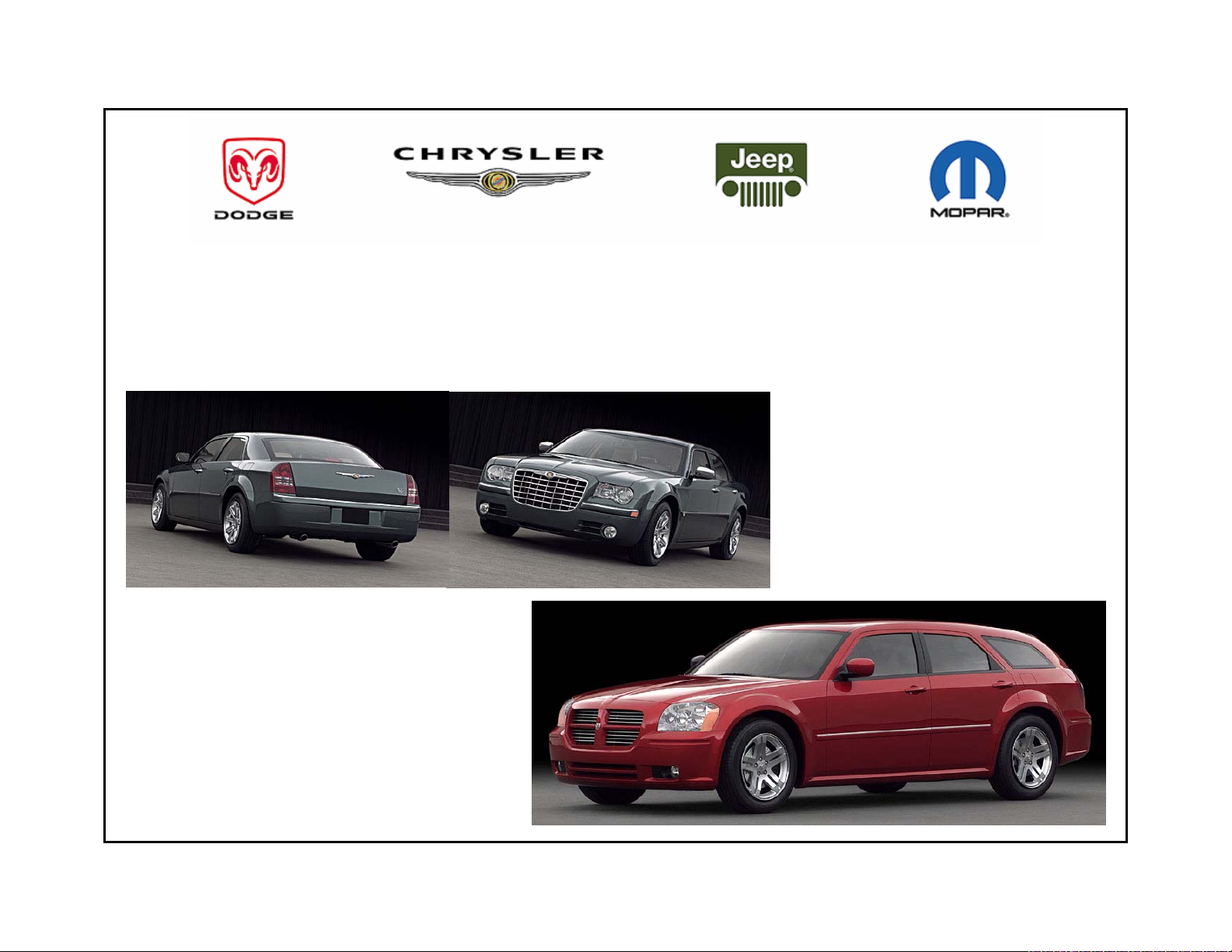
Introduction
CHRYSLER 300, 300C,
300 Touring
and
DODGE MAGNUM
This manual has been prepared for use by all body technicians involved in the repair of the 300, 300C, 300 Touring &
Dodge Magnum
This manual shows:
- Typical unibody panels contained in these vehicles - The types of welds for the panel
- The weld locations for these panels - Proper sealer types and correct locations
Body Construction Characteristics......................
History of Collision Repair...................................
Body Code Plate Information..............................
Vehicle Identification Number Information...........
Corrosion Protection............................................
Welded Panel Replacement................................
Sealer Locations..................................................
Sound Deadner Locations...................................
Structural Adhesive Locations.............................
Frame/Body Dimensions.....................................
Additional Support/Information............................
DaimlerChrysler Motors Corporation reserves the right to make improvements in design or to change specifications to
these vehicles without incurring any obligation upon itself.
Page 5

BODY CONSTRUCTION CHARACTERISTICS
Definitions of Steels used in the 300,300C, & Magnum:
MS 66 - Represents an uncoated Hot Rolled Steel Sheet used mainly for interior braces and reinforcements.
MS 67 - Represents an uncoated Cold Rolled Sheet structural steel used in areas where structural integrity is critical.
EG., the type of steel used for the "A" pillar.
MS 264 - Represents an uncoated high strength low alloy (HSLA) steel used in applications where structural integrity is
critical.
MS 6000-44A - Low carbon, hot dipped galvanneal (or EGA) with 45 g/m² minimun coating weight on both sides.
- Most common Sheet Steel product used by Chrysler
MS 6000-44VA - 50 ksi min. yield strength, HSLA, killed steel, with 44 g/m² minimun coating weight on both sides. -
- Most common high strength coated steel product used by Chrysler
BODY CONSTRUCTION CHARACTERISTICS
The following measures have been implemented in order to provide maximum corrosion prevention and protection.
1. The use of galvannealed coatings throughout the body structure.
2. Ecoat is used on the complete body in all instances.
3. Body sealing.
4. Stone-chipping resistant primer application.
5. Underbody corrosion prevention.
Back To Index
Page 6
CHRYSLER 300, 300C, 300 TOURING, &
DODGE MAGNUM
CAR LINE
CHART A C D D MIN
PART L 4 4 4 PART GAGE
L 8 8 9 DESCRIPTION METRIC MATERIAL
#
4 C TROUGH - DECK OPENING SIDE RT 1.24 MS-6000 44A
C TROUGH - DECK OPENING SIDE LT
4 8 TROUGH - DECK OPENING SIDE RT 1.24 MS-6000 44A
8 TROUGH - DECK OPENING SIDE LT
4 D TROUGH - QTR PANEL DRAIN UPR RT 1.52 MS-6000 44VA-040SK
D TROUGH - QTR PANEL DRAIN UPR LT
7 A BRACKET - FRT SUSP UPR CONTROL ARM R 1.98 MS-6000 44VA-050XK
A BRACKET - FRT SUSP UPR CONTROL ARM L
9 A PANEL - RR WHEELHOUSE INR RT 1.22 MS-6000 44A
A PANEL - RR WHEELHOUSE INR LT
10 A REINFORCEMENT - SILL FRT RT 0.99 MS-6000 44VA-050-XF
A REINFORCEMENT - SILL FRT LT
12 A PANEL - RR WHEELHOUSE OTR RT 0.61 MS-6000 44A
A PANEL - RR WHEELHOUSE OTR LT
13 C PANEL - BODY SIDE INR RT 1.42 MS-6000 44VA-050-XK
C PANEL - BODY SIDE INR LT
COMPONENT CHART PART SPECIFICATION LIST
Back To Index
Page 7

CHRYSLER 300, 300C, 300 TOURING, &
DODGE MAGNUM
COMPONENT CHART PART SPECIFICATION LIST
13 8 PANEL - BODY SIDE INR RT 1.42 MS-6000 44VA-050-XK
8 PANEL - BODY SIDE INR LT
13 D PANEL - BODY SIDE INR RT 1.42 MS-6000 44VA-050-XK
D PANEL - BODY SIDE INR LT
15 C PANEL - BODY SIDE OTR RT 0.79 MS-6000 44AE
C PANEL - BODY SIDE OTR LT
15 8 PANEL - BODY SIDE OTR RT 0.79 MS-6000 44AE
8 PANEL - BODY SIDE OTR LT
15 D PANEL - BODY SIDE OTR RT 0.79 MS-6000 44AE
D PANEL - BODY SIDE OTR LT
17 A PANEL - RR SHOCK MOUNTING RT 2.00 MS-6000 44VA-050-XK
A PANEL - RR SHOCK MOUNTING LT
18 A TAPPING PLATE - DOOR HINGE FRT RT 2.40 MS-66
A TAPPING PLATE - DOOR HINGE FRT LT
18 A TAPPING PLATE - DOOR HINGE FRT LT 2.40 MS-66
23 A BRACKET - ENGINE CRADLE MOUNTING UPR 1.80 MS-6000 44VA-050-XK
A BRACKET - ENGINE CRADLE MOUNTING UPR
25 A REINFORCEMENT - TOEBOARD CROSSMEMBER 1.98 MS-6000 44VA-080-XK
A REINFORCEMENT - TOEBOARD CROSSMEMBER
26 A PANEL - UPR LOAD PATH OTR RT 0.89 MS-6000 44VA-050-XK
A PANEL - UPR LOAD PATH OTR LT
Back To Index
Page 8

CHRYSLER 300, 300C, 300 TOURING, &
DODGE MAGNUM
COMPONENT CHART PART SPECIFICATION LIST
27 A BRACKET - ENGINE CRADLE MOUNTING UPR 1.47 MS-6000 44VA-050-XK
28 A SPACER - BRAKE BOOSTER 3.50 MS - 588 -B - 3
31 A PANEL - SHOCK TOWER MOUNTING FRT RT 2.08 MS-6000 44A
A PANEL - SHOCK TOWER MOUNTING FRT LT
32 A PANEL - FRT WHEELHOUSE RR RT 0.76 MS-6000 44A
A PANEL - FRT WHEELHOUSE RR LT
33 D PANEL - HOOD INR 0.90 MS-8580 A96022-T43
C PANEL - HOOD INR
8 PANEL - HOOD INR
34 D PANEL - HOOD OTR 0.90 MS-8580 A96022-T4E29
C PANEL - HOOD OTR
8 PANEL - HOOD OTR
35 A TAPPING PLATE - HOOD INR PANEL HINGE 2.00 MS-8580 A96022-T4
A TAPPING PLATE - HOOD INR PANEL HINGE
36 C CROSSMEMBER - HEADLAMP MOUNTING MS-DB-41/MS-6000 44VA
D CROSSMEMBER - HEADLAMP MOUNTING
8 CROSSMEMBER - HEADLAMP MOUNTING
38 A PAN - TORQUE BOX RT 2.50 MSDB543,CPN2194,TYPEA
39 A PANEL - FRT WHEELHOUSE FRT RT 1.42 MS-6000 44VA-050
A PANEL - FRT WHEELHOUSE FRT LT
41 A TAP PLATE - FLOATING 1.98 MS-66
44 A PANEL - LWR RADIATOR CROSSMEMBER 0.79 MS-67
Back To Index
Page 9

CHRYSLER 300, 300C, 300 TOURING, &
DODGE MAGNUM
COMPONENT CHART PART SPECIFICATION LIST
49 C REINF - HOOD INR PANEL SLAM 1.25 MS-8580 A96022-T4
D REINFORCEMENT - HOOD INR PANEL SLAM
8 REINFORCEMENT - HOOD INR PANEL SLAM
51 A PANEL - RAIL FRT COVER RT 1.54 MS-6000 44VA-590DT
A PANEL - RAIL FRT COVER LT
53 A PANEL - FRT SIDE RAIL INR RT 1.54 MS-6000 44VA-590DT
A PANEL - FRT SIDE RAIL INR LT
54 A PANEL - COWL LWR 0.89 MS-6000 44A
55 A BRACKET - ICU 1.47 MS-6000 44A
56 A PANEL - COWL UPR 0.71 MS-6000 44A
58 A PANEL - DASH 0.71 MS-6000 44A
62 A PANEL - EXTENSION FRT RAIL OTR RT 1.98 MS-6000 44VA-050-XK
A PANEL - EXTENSION FRT RAIL OTR LT
63 A PANEL - EXTENSION FRT RAIL INR RT 1.88 MS-6000 44VA-050-XK
A PANEL - EXTENSION FRT RAIL INR LT
64 A SHIELD - SPLASH RR WHEELHOUSE RT 2.00 MSDB-543,TYPE A
A SHIELD - SPLASH RR WHEELHOUSE LT
65 A REINF - RAIL TO TUNNEL RT 1.04 MS-264 035-SK
A REINF - RAIL TO TUNNEL LT
66 A COVER PLATE - RAIL RR RT 1.24 MS-6000 44VA-050-XK
A COVER PLATE - RAIL RR LT
Back To Index
Page 10

CHRYSLER 300, 300C, 300 TOURING, &
DODGE MAGNUM
COMPONENT CHART PART SPECIFICATION LIST
67 A ROD ASSY - HOOD SUPPORT 8.00 MS-284
68 A REINF - TUNNEL 1.19 MS-264 050-XF
69 A EXTENSION - RAIL FRT RT 1.40 MS-264 050-XK
A EXTENSION - RAIL FRT LT
70 A PANEL - FRT FLOOR PAN TUNNEL CTR 0.89 MS-6000 44VA-050-XF
71 A TAPPING PLATE - HINGE BODY 1.27 MS-6000
72 A REINF - I/P BRACKET RT 2.00 MS-66
A REINF - I/P BRACKET LT
73 A PANEL - LOAD PATH BEAM UPR INR RT 0.89 MS-6000 44VA-050-XF
A PANEL - LOAD PATH BEAM UPR INR LT
76 A RETAINER - RR DOOR STRIKER RT 1.52 MS-66
A RETAINER - RR DOOR STRIKER LT
77 A CROSSMEMBER - ISOFIX 1.50 MS-264 050-XK
78 A GLASS ASSY - WINDSHIELD 5.10 MS-10472-B
79 C PANEL - ROOF OTR 0.74 MS-67
8 PANEL - ROOF OTR
D PANEL - ROOF OTR
D PANEL - ROOF OTR
80 A REINF - HOOD INR PANEL STRIKER 2.00 MS-8580 A96022-T4
Back To Index
Page 11

CHRYSLER 300, 300C, 300 TOURING, &
DODGE MAGNUM
COMPONENT CHART PART SPECIFICATION LIST
81 C GLASS ASSY - RR WDO ELEC HEATED E-MA 3.90 MS-10472-C
8 GLASS ASSY - RR WINDOW ELECTRIC HEAT "
D GLASS ASSY - RR WINDOW ELECTRIC HEAT " MS-7588
82 C HEADER - RR WINDOW OPENING 0.74 MS-67
82 8 HEADER - RR WINDOW OPENING 0.74 MS-67
82 D HEADER - REAR UPR 1.30 MS-6000 44A
84 D HEADER - REAR LWR 0.89 MS-67
85 A HEADER - WINDSHIELD OPENING 0.74 MS-67
86 A CROSSMEMBER - FRT SEAT FRT RT 1.24 MS-264 050-XF
A CROSSMEMBER - FRT SEAT FRT LT
87 A CROSSMEMBER - FRT SEAT RR RT 1.24 MS-264 050-XF
A CROSSMEMBER - FRT SEAT RR LT
89 A EXTENSION - TUNNEL 1.47 MS-6000 44A-050-XF
90 C D BUMPER - HOOD ADJUSTER 0.00 MS-Z-77
91 A CROSSMEMBER - RR KICK-UP 0.99 MS-6000 44A
92 A BRACE - FRONT SHOCK TOWER 1.00 MS-67
94 A TAP PLATE - REAR DOOR UPR RT 2.00 MS-66
94 A TAP PLATE - REAR DOOR UPR RT 2.00 MS-66
96 A PAN - CTR FLOOR PAN 0.66 MS-6000 44A
Back To Index
Page 12

CHRYSLER 300, 300C, 300 TOURING, &
DODGE MAGNUM
COMPONENT CHART PART SPECIFICATION LIST
98 A PAN - REAR FLOOR 0.71 MS-6000 44A
101 C REINF - RR SHELF PANEL RR 0.70 MS-6000 44A
101 8 REINF - RR SHELF PANEL RR 0.70 MS-6000 44A
102 C PANEL - DECK LID OTR 0.90 MS-8580 A96022-T43
102 8 PANEL - DECK LID OTR 0.76 MS-6000 44WAE-025-SK
102 D PANEL - LIFTGATE OTR LWR 0.81 MS-6000 44AE
103 C PANEL - DECK LID INR 1.00 MS-8580 A96022-T43
103 8 PANEL - DECK LID INR 0.71 MS-6000 44A
103 D PANEL - LIFTGATE INR 1.22 MS-6000 44AE
105 C PANEL - DECK OPENING LWR INR 0.72 MS-6000 44A
105 8 PANEL - DECK OPENING LWR INR 0.71 MS-6000 44A
105 D REINF - DECK OPENING LWR INR 0.81 MS-67
106 C PANEL - DECK OPENING LWR OTR 0.72 MS-6000 44A
106 8 PANEL - DECK OPENING LWR OTR 0.71 MS-6000 44A
106 D PANEL - DECK OPENING LWR OTR 1.12 MS-6000 44A
107 A TAP PLATE - FRONT DOOR UPR RT 2.00 MS-67
Back To Index
Page 13

CHRYSLER 300, 300C, 300 TOURING, &
DODGE MAGNUM
COMPONENT CHART PART SPECIFICATION LIST
110 A TAPPING PLATE - DOOR HINGE RR LWR RT 2.40 MS-66
A TAPPING PLATE - DOOR HINGE RR LW R LT
112 A CROSSMEMBER - RR SUSPENSION RR 1.75 MS-6000 44VA-050-XK
113 A BRACKET - ENGINE CRADLE MOUNTING LWR 1.80 MS-6000 44VA-050-XK
A BRACKET - ENGINE CRADLE MOUNTING LWR
114 A RAIL - RR INR RT 1.14 MS-6000 44VA-050-XK
A RAIL - RR INR LT
115 A BRACKET - HEADLAMP MOUNTING RT 1.24 MS-6000 44A
A BRACKET - HEADLAMP MOUNTING LT
117 D PANEL - FRONT FENDER RT 0.71 MS-6000 44WAE-025
D PANEL - FRONT FENDER LT
C PANEL - FRONT FENDER RT
C PANEL - FRONT FENDER LT
117 8 PANEL - FRONT FENDER RT 0.71 MS-6000 44WAE-025
8 PANEL - FRONT FENDER LT
118 C D PANEL - FRT DOOR INR RT 0.75 MS-6000 44A
C D PANEL - FRT DOOR INR LT
118 8 PANEL - FRT DOOR INR RT 0.75 MS-6000 44A
8 PANEL - FRT DOOR INR LT
119 C D REINF - FRT DOOR BELT INR RT 0.90 MS-264 050-XK
C D REINF - FRT DOOR BELT INR LT
119 8 REINF - FRT DOOR BELT INR RT 1.20 MS-264 050-XK
8 REINF - FRT DOOR BELT INR LT
Back To Index
Page 14

CHRYSLER 300, 300C, 300 TOURING, &
DODGE MAGNUM
COMPONENT CHART PART SPECIFICATION LIST
121 A SHIELD - HEAT FRT FLOOR TUNNEL LT 0.50 MS-8580
123 A SHIELD - HEAT FRT FLOOR FRT RT 3.00 MS-8580
A SHIELD - HEAT FRT FLOOR FRT LT
124 A BAR - IMPACT FRT DOOR RT 2.40 MS-8010 D
A BAR - IMPACT FRT DOOR LT
125 D ROD - LIFTGATE GAS PROP 0.00 N/A
125 C PROP ASSY - DECK LID 0.00 N/A
125 8 PROP ASSY - DECK LID 0.00 N/A
126 A EXTENSION - CROSSMEMBER END SUPPORT 2.24 MS-6000 44VA-050-XK
A EXTENSION - CROSSMEMBER END SUPPORT
128 C D REINF - FRT DOOR BELT OTR RT 0.75 MS-6000 44A
C D REINF - FRT DOOR BELT OTR LT
128 8 REINF - FRT DOOR BELT OTR RT 0.75 MS-6000 44A
8 REINF - FRT DOOR BELT OTR LT
129 C D PANEL - RR DOOR INR RT 0.74 MS-6000 44A
C D PANEL - RR DOOR INR LT
129 8 PANEL - RR DOOR INR RT 0.74 MS-6000 44A
8 PANEL - RR DOOR INR LT
132 C D PANEL - REAR DOOR OUTER RT 0.76 MS-6000 44VAE-030-HK
C D PANEL - REAR DOOR OUTER LT
Back To Index
Page 15

CHRYSLER 300, 300C, 300 TOURING, &
DODGE MAGNUM
COMPONENT CHART PART SPECIFICATION LIST
132 8 PANEL - REAR DOOR OUTER RT 0.76 MS-6000 44VAE-030-HK
8 PANEL - REAR DOOR OUTER LT
133 A C D REINFORCEMENT - NONE 2.00 MS-6000 44A
133 A C D REINFORCEMENT - NONE 2.00 MS-6000 44A
134 A BAR - IMPACT RR DOOR RT 2.20 MS-8010
A BAR - IMPACT RR DOOR LT
137 C PANEL - REAR SHELF 0.89 MS-67
137 8 PANEL - REAR SHELF 0.89 MS-67
139 C D PANEL - FRT DOOR OTR RT 0.76 MS-6000
C D PANEL - FRT DOOR OTR LT
139 8 PANEL - FRT DOOR OTR RT 0.76 MS-6000
8 PANEL - FRT DOOR OTR LT
140 A SPACER - CRADLE RR 3.00 MS-1560
141 C D REINFORCEMENT - REAR DOOR BELT OTR R 0.76 MS-6000
C D REINFORCEMENT - REAR DOOR BELT OTR L
141 8 REINFORCEMENT - REAR DOOR BELT OTR R 0.76 MS-6000
8 REINFORCEMENT - REAR DOOR BELT OTR L
142 A EXTENSION - IMPACT BEAM FRT DOOR FRT 1.50 MS-264 050 XK
A EXTENSION - IMPACT BEAM FRT DOOR FRT
143 A EXTENSION - IMPACT BEAM FRT DOOR RR 1.50 MS-264 050 XK
A EXTENSION - IMPACT BEAM FRT DOOR RR
Back To Index
Page 16

CHRYSLER 300, 300C, 300 TOURING, &
DODGE MAGNUM
COMPONENT CHART PART SPECIFICATION LIST
144 A EXTENSION - RR DOOR IMPACT BAR FRT R 1.50 MS-264 050 XK
A EXTENSION - REAR DOOR IMPACT BAR FRT
145 A EXTENSION - RR DOOR IMPACT BAR RR RT 1.50 MS-264
A EXTENSION - REAR DOOR IMPACT BAR RR
146 A SPACER - ENGINE CRADLE MOUNTING FRT 3.00 MS-345 TYPE 5
148 A REINFORCEMENT - REAR RAIL OTR RT 1.98 MS-6000 44VA-050-XK
A REINFORCEMENT - REAR RAIL OTR LT
149 C D BRACKET - BUMPER RR 2.00 MS-6000 44VA-050-XK
149 C D BRACKET - BUMPER RR 2.00 MS-6000 44VA-050-XK
152 A REINF - SEAT BELT ANCHOR RR INBOARD 1.98 MS-6000 44VA-050-XK
154 C REINF - C-PILLAR RT 1.19 MS-6000 44VA-050-XK
C REINF - C-PILLAR LT
D REINF - C-PILLAR RT
D REINF - C-PILLAR LT
154 8 REINF - C-PILLAR RT 1.19 MS-6000 44VA-050-XK
8 REINF - C-PILLAR LT
155 C REINF - DECK LID LATCH MOUNTING 2.00 MS-8580 A96022-T4
155 8 REINF - DECK LID LATCH MOUNTING 1.80 MS-66
156 D REINF - LIFTGATE HINGE MOUNTING RT 2.03 MS-66
D REINF - LIFTGATE HINGE MOUNTING LT
Back To Index
Page 17

Back To Index
156 C REINF - DECK LID HINGE TO DECK LID M 2.00 MS-8580 A96022-T4
C REINF - DECK LID HINGE TO DECK LID M
156 8 REINF - DECK LID HINGE TO DECK LID M 2.00 MS-66
8 REINF - DECK LID HINGE TO DECK LID M
157 A BRACKET - LWR RADIATOR CROSSMEMBER S 1.98 MS-264 050-XK
A BRACKET - LWR RADIATOR CROSSMEMBER S
159 A STRIKER - HOOD 7.00 MS-5378 B
160 D EXTENSION - QTR OTR PANEL LWR RR RT 0.89 MS-6000 44A
D EXTENSION - QTR OTR PANEL LWR RR LT
160 C EXTENSION - QTR OTR PANEL LWR RR RT 0.66 MS-6000 44A
C EXTENSION - QTR OTR PANEL LWR RR LT
160 8 EXTENSION - QTR OTR PANEL LWR RR RT 0.66 MS-6000 44A
8 EXTENSION - QTR OTR PANEL LWR RR LT
161 A BRACKET - VAPOR CANISTER 1.60 MS-6000 44A
A BRACKET - VAPOR CANISTER
162 D PANEL - LIFTGATE OTR UPR 0.81 MS-6000 44AE
164 C D DOOR - FUEL FILLER 0.79 MS-6000 44AE
164 8 DOOR - FUEL FILLER 0.79 MS-6000 44AE
165 C D REINFORCEMENT - REAR DOOR BELT INR R 0.90 MS-264 050-XK
C D REINFORCEMENT - REAR DOOR BELT INR L
165 8 REINFORCEMENT - REAR DOOR BELT INR R 0.90 MS-264 050-XK
CHRYSLER 300, 300C, 300 TOURING, &
DODGE MAGNUM
COMPONENT CHART PART SPECIFICATION LIST
Page 18

CHRYSLER 300, 300C, 300 TOURING, &
DODGE MAGNUM
COMPONENT CHART PART SPECIFICATION LIST
166 C D REINF - BODY SIDE RT 1.42 MS-6000 44VA-050-XK
C D REINF - BODY SIDE LT
166 8 REINF - BODY SIDE RT 1.42 MS-6000 44VA-050-XK
8 REINF - BODY SIDE LT
167 C BRACKET - LOCK CYLINDER ATTACH 0.90 MS-67
167 8 BRACKET - LOCK CYLINDER ATTACH 1.20 MS-66
168 C 8 PANEL - RR SHELF SUPPORT RT 1.24 MS-67
C 8 PANEL - RR SHELF SUPPORT LT
172 A SPACER - TOWER BRACE 1.98 MS-66
173 A BRACKET - BATTERY RETAINER MS-DB21
176 C D REINF - B-PILLAR 1.52 MS-264 050-XK
C D REINF - B-PILLAR
176 8 REINF - B-PILLAR 1.52 MS-264 050-XK
8 REINF - B-PILLAR
178 A REINF - BRAKE BOOSTER 1.88 MS-66
179 A TAPPING PLATE - NONE 2.54 MS-66
180 A RAIL - RR OTR RT 1.42 MS-6000 44VA-050-XK
A RAIL - RR OTR LT
181 A COVER PLATE - RR RAIL EXTENSION RT 0.79 MS-6000 44A
A COVER PLATE - RR RAIL EXTENSION LT
Back To Index
Page 19
CHRYSLER 300, 300C, 300 TOURING, &
DODGE MAGNUM
COMPONENT CHART PART SPECIFICATION LIST
183 A HINGE ASSY - FRT DOOR LWR RT 6.00 MS-264 050-X
A HINGE ASSY - FRT DOOR LWR LT
184 A HINGE ASSY - RR DOOR LWR RT 6.00 MS-264 050-X
A HINGE ASSY - RR DOOR LWR LT
186 C D HOUSING - RR QTR OTR PANEL FUEL FILL 1.00 MS-6000 44A
8
188 A BRACKET - CRADLE ATTACHING RT 1.98 MS-6000 44VA-050-XK
A BRACKET - CRADLE ATTACHING LT
189 A BRACKET - WIPER MODULE MTG 1.88 MS-6000 44A
190 A BRACKET - FENDER ATTACH 1.02 MS-2501
191 C HINGE ASSY - DECK LID COMP RT 3.00 MS-264 030-S
C HINGE ASSY - DECK LID COMP LT
191 8 HINGE ASSY - DECK LID COMP RT 3.00 MS-264 030-S
8 HINGE ASSY - DECK LID COMP LT
193 A BRACKET - HEADLAMP MOUNTING RT 1.98 MS-66
A BRACKET - HEADLAMP MOUNTING LT
198 A HINGE ASSY - HOOD RT 3.00 MS-264 050-X
A HINGE ASSY - HOOD LT
199 A HINGE ASSY - FRT DOOR UPR RT 6.00 MS-264 050-X
A HINGE ASSY - FRT DOOR UPR LT
Back To Index
Page 20

CHRYSLER 300, 300C, 300 TOURING, &
DODGE MAGNUM
COMPONENT CHART PART SPECIFICATION LIST
200 A HINGE ASSY - RR DOOR UPR RT 6.00 MS-264 050-X
A HINGE ASSY - RR DOOR UPR LT
206 A BRKT - RETAINER ENGINE CRADLE T/PLT 1.44 MS-6000 55P
207 A REINF - SPARE TIRE HOLD DOWN 0.99 MS-67
211 A REINF - DASH PANEL 1.22 MS-6000 VA-050
212 A PANEL - TOEBOARD CROSSMEMBER 1.80 MS-6000 44VA-600DT
214 A REINF - JOUNCE 1.47 MS-6000 44VA-040-XK
215 C BRACKET - DISABLED VEHICLE TIE DOWN 1.98 MS-264 050-XK
218 C 8 TAPPING PLATE - DECK LID STRIKER 2.00 MS-66
218 D REINF - STRIKER PLATE 1.52 MS-66
219 C 8 STRIKER - D/LID LATCH 1.80 MS-67
220 A REINF - SHOCK TOW ER TO LOAD BEAM RT 1.47 MS-6000 44A
A REINF - SHOCK TOWER TO LOAD BEAM LT
222 A BRACKET - TRANS MOUNTING RT 1.83 MS-6000 44A
A BRACKET - TRANS MOUNTING LT
223 A REINF - FRT SIDE RAIL BUMPER MOUNTIN 1.98 MS-6000 44VA-050-XK
A REINF - FRT SIDE RAIL BUMPER MOUNTIN
224 A BRACKET - TOWER BRACE WIPER ATTACHME 1.47 MS-264 050-XK
226 A REINF - FRT SHOCK TOWER RT 1.40 MS-6000 44A
Back To Index
Page 21

CHRYSLER 300, 300C, 300 TOURING, &
DODGE MAGNUM
COMPONENT CHART PART SPECIFICATION LIST
228 A DOUBLER - FRT SIDE RAIL RT 1.80 MS-6000 44A
A DOUBLER - FRT SIDE RAIL LT
233 A SHIELD - FENDER WHEELHOUSE SPLASH RT 2.50 MSDB-543,CPN2194,TYPEA
A SHIELD - FENDER WHEELHOUSE SPLASH LT
235 A TRAY ASSY - BATTERY MS-DB21
236 C D TAPPING PLATE - DOOR HINGE RR UPR RT 2.40 MS-66
C D TAPPING PLATE - DOOR HINGE RR UPR LT
238 C D BOW - ROOF 1.98 MS-264 050-XK
238 8 BOW - ROOF 1.98 MS-264 050-XK
239 A PAN - TORQUE BOX LT 2.50 MSDB-543,CPN2194,TYPEA
242 A CROSSMEMBER - REAR SUSPENSION FRT 1.04 MS-6000 44VA-050-XK
243 A REINF - KICKUP CROSSMEMBER 1.35 MS-6000 44VA-050-XK
244 A BRACKET - CTR BEARING MOUNTING RT 1.52 MS-6000 44A
A BRACKET - CTR BEARING MOUNTING LT
245 C PANEL - TAIL LAMP MOUNTING RT 0.76 MS-6000 44A
C PANEL - TAIL LAMP MOUNTING LT
245 8 PANEL - TAIL LAMP MOUNTING RT 0.76 MS-6000 44A
8 PANEL - TAIL LAMP MOUNTING LT
245 D PANEL - TAIL LAMP MOUNTING RT 0.89 MS-6000 44A
D PANEL - TAIL LAMP MOUNTING LT
Back To Index
Page 22

CHRYSLER 300, 300C, 300 TOURING, &
DODGE MAGNUM
COMPONENT CHART PART SPECIFICATION LIST
247 D TAP PLATE - CROSS CAR BEAM UPR 2.00 MS-66
247 C D TAPPING PLATE - SEAT BELT TURNING LO 2.50 MS-66
250 C REINF - RR BELT RETRACTOR RT 1.00 MS-67
C REINF - RR BELT RETRACTOR LT
250 8 REINF - RR BELT RETRACTOR RT 1.00 MS-67
8 REINF - RR BELT RETRACTOR LT
251 D REINF - LIFTGATE HINGE BODY HALF RT 1.50 MS-66
252 A BRACE - REINFORCEMENT TUNNEL CTR 1.98 MS-6000 66V-050XK
253 D REINF - LIFTGATE PROP ROD RT 1.22 MS-67
D REINF - LIFTGATE PROP ROD LT
254 A BEAM ASSY - BUMPER FRT 1.20 MS-264 120-XF
255 A BEAM - REAR BUMPER 1.60 MS-264 120-XF
256 C D TAP PLATE - NONE 1.80 MS-66
258 D REINF - LIFTGATE LATCH 1.00 MS-67
261 C TAPPING PLATE - DECK LID HINGE 1.80 MS-66
261 8 TAPPING PLATE - DECK LID HINGE 2.00 MS-66
8
261 D TAPPING PLATE - PROP ROD RT 1.50 MS-67
Back To Index
Page 23

CHRYSLER 300, 300C, 300 TOURING, &
DODGE MAGNUM
COMPONENT CHART PART SPECIFICATION LIST
265 D REINF - WIPER MOUNTING 1.00 MS-67
268 D REINF - BODY SIDE INR PANEL D-PILLAR 1.19 MS-264
D REINF - BODY SIDE INR PANEL D-PILLAR
269 C 8 CROSSMEMBER - RR SHELF 0.89 MS 67
271 A C D TAPPING PLATE - NONE 1.40 MS-66
271 A C D TAPPING PLATE - NONE 1.40 MS-66
272 A TAPPING PLATE - CROSSMEMBER 3.50 MS-66
274 A TAPPING PLATE - BODY SIDE FRT DOOR L 2.40 MS-66
A TAPPING PLATE - BODY SIDE FRT DOOR L
277 A TAPPING PLATE - SIDE AIR BAG SENSOR 2.00 MS-66
278 A PANEL - FRT FLOOR PAN RT 0.61 MS-6000 44A
A PANEL - FRT FLOOR PAN LT
280 A TAPPING PLATE - SEAT BELT RETRACTOR 3.00 MS-66
280 A TAPPING PLATE - SEAT BELT RETRACTOR 3.00 MS-66
281 C BRACKET - CHILD TETHER ATTACH 2.67 MS-264 050-XK
282 C 8 REINF - CTR SEAT BELT RETRACTOR 1.65 MS-264 050-XK
283 A REINFORCEMENT - CROSSMEMBER REAR SUS 3.48 MS-264 050-XK
A REINFORCEMENT - CROSSMEMBER REAR SUS
Back To Index
Page 24

CHRYSLER 300, 300C, 300 TOURING, &
DODGE MAGNUM
COMPONENT CHART PART SPECIFICATION LIST
284 A REINF - RR RAIL INR RR RT 1.52 MS-6000 44VA-080-XK
A REINF - RR RAIL INR RR LT
285 A GUSSET - ISOFIX 1.80 MS-264 050-XK
A GUSSET - ISOFIX
288 D BRACKET - SEAT BACK LATCH RR UPR RT 1.09 MS-67
D BRACKET - SEAT BACK LATCH RR UPR LT
289 D PANEL - SEAT STRIKER RT 1.09 MS-67
D PANEL - SEAT STRIKER LT
290 C D CHANNEL - FRONT DOOR GLASS RUN RT 0.90 MS-6000 44A
C D CHANNEL - FRONT DOOR GLASS RUN LT
290 8 CHANNEL - FRONT DOOR GLASS RUN RT 0.90 MS-6000 44A
8 CHANNEL - FRONT DOOR GLASS RUN LT
291 C D REINF - FUEL FILLER DOOR HINGE 1.20 MS-6000 44A
8
293 D REINF - ROOF RACK FRT 1.00 MS-67
D REINF - ROOF RACK RR
296 C D CHANNEL - RR DOOR GLASS RUN RT 0.90 MS-6000 44A
C D CHANNEL - RR DOOR GLASS RUN LT
296 8 CHANNEL - RR DOOR GLASS RUN RT 0.90 MS-6000 44A
8 CHANNEL - RR DOOR GLASS RUN LT
298 C PANEL - ROOF SUNROOF 0.74 MS-67
8 PANEL - ROOF SUNROOF
D PANEL - ROOF SUNROOF
Back To Index
Page 25

CHRYSLER 300, 300C, 300 TOURING, &
DODGE MAGNUM
COMPONENT CHART PART SPECIFICATION LIST
299 C D REINF - SUNROOF 1.20 MS-6000 44A
8 REINF - SUNROOF
329 A REINF - SUN VISOR MOUNTING TRIM 1.80 MS-66
A REINF - SUN VISOR MOUNTING TRIM
Back To Index
Page 26

Back To Index
Page 27

HISTORY OF COLLISION REPAIR
Time was, if you had an accident, the call went out to the insurance company - to the collision shop - or several shops get the lowest bid and in no time at all, the vehicle was repaired.
The facilities, training, and equipment were simple. Use a torch to cut, shape, and bend. Use something substantial as
an anchoring point - maybe a tree and then just pull.
Use plenty of solder or body putty to make it look good. With the frame and body vehicle, the job was easy; first
straighten the frame - then fix the mechanical components and the body work was cosmetic. This was all well and good
until the mid - '70s.
Then, the designers, engineers, and manufacturers had to find ways to make the vehicles energy efficient - and that
meant unibody cars. The unibody concept wasn't new - back in the '30s the Chrysler Air Flow had it - race cars have it and now the driving public worldwide has it.
The change came quickly. Manufacturers devoted time, money, and talent to delvelop the unibody car.
The public was ready to buy and did!
But then came the problem! The collision repair industry wasn't given the luxury of taking their time to train people in the
new technology - or take time to plan for new equipment.
The collision happened and the vehicle had to be fixed. Cars that were repairable were being totalled.
Cars that were repaired were not repaired correctly. Everybody was in a quandary - auto manufacturer - insurance
company - repair equipment people - body shops - and repair technicians.
The problem started in the early '70s and body shops are still catching up today. Yesterday's "ding" is today's "crash". It
takes trained technicians and sophisticated equipment to do the repair today.
That's why DaimlerChrysler is taking the time and effort to get the right information into the hands of the people that
handle the repair job. Back To Index
Page 28
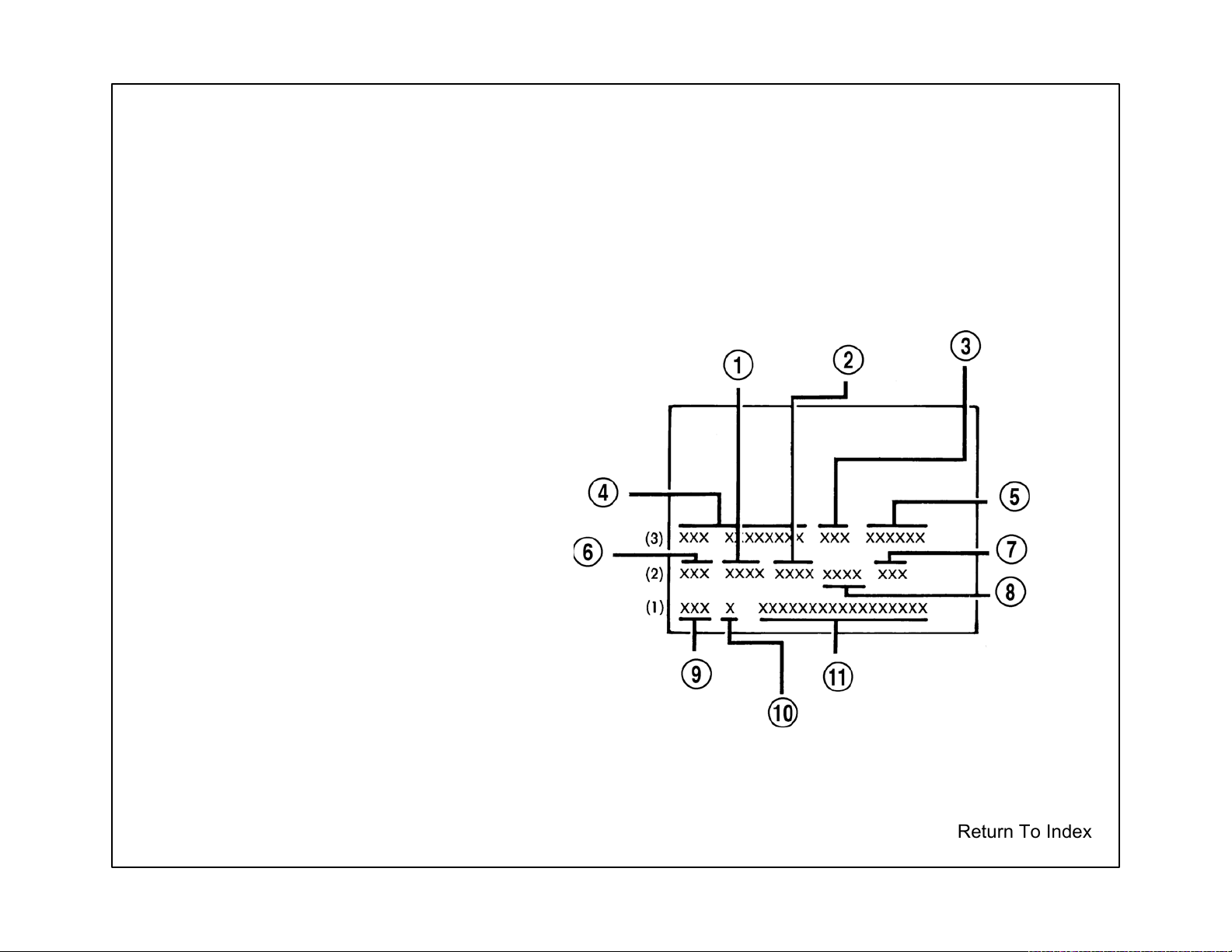
BODY CODE PLATE DESCRIPTION
The Body Code Plate is located in the engine compartment on the right headlamp mounting bracket/
radiator support. There are seven lines of information on the body code plate. Lines 4, 5, 6, and 7 are
not used to define service information. Information reads from left to right, starting with line 3 in the
center of the plate to line 1 at the bottom of the plate.
BODY CODE PLATE
1 - PRIMARY PAINT
2 - SECONDARY PAINT
3 - VINYL ROOF
4 - VEHICLE ORDER NUMBER
5 - CAR LINE SHELL
6 - PAINT PROCEDURE
7 - ENGINE
8 - TRIM
9 - TRANSMISSION
10 - MARKET
11 - VIN
NOTE: Paint Code may also be found on safety certification label on inside of driver side door jamb.
Return To Index
Page 29
VIN DECODING INFORMATION
POSITION INTERPRETATION CODE = DESCRIPTION
1 Country of Origin 1 = Manufactured by DaimlerChrysler Canada Inc.
C = Chrysler
2 Make
3 Vehicle Type
Restraint System
Gross Vehicle Weight
4
5 Vehicle Line
6 Series
7 Body Style
8 Engine
9 Check Digit 0 through 9 or X
10 Model Year 5 = 2005
11 Assembly Plant H = Brampton Assembly
12 Through 17 Vehicle Build Sequence
Rating H = 6001-7000 lbs.
D = Dodge
3 = Passenger Car
4 = Multipurpose Passenger Vehicle With Side Airbags
8 = Multipurpose Passenger Vehicle with Side Airbags
J = Restraint System Air bags Front Next Generation Multi-Stage
Sales Code (CG1) Without Side Air Bags Sales Code (CGS)
A = 300 / 300C / SRT-8 (RWD)
K = 300 (AWD)
V = TBD (RWD)
Z = TBD (AWD)
2 = L Low Line
3 = M Medium
4 - H High Line
5 = P Premium
6 = S Sport
7 = S Special
3 = LX - 48
8 = LX - 49
R = 2.7L V-6 cyl. DOHC 24 Valve MPI Gasoline
G = 3.5L V-6 cyl. High Output 24 Valve MPI Gasoline
H = 5.7L V-8 cyl. Gasoline
T = 2.7L V-6 cyl. DOHC 24 Valve MPI Gasoline
V = 3.5L V-6 cyl. High Output 24 Valve MPI Gasoline
2 = 5.7L V-8 cyl. HEMI Multiple Displacement Gasoline
Six Digit Number Assigned By Assembly Plant
Back To Index
Page 30
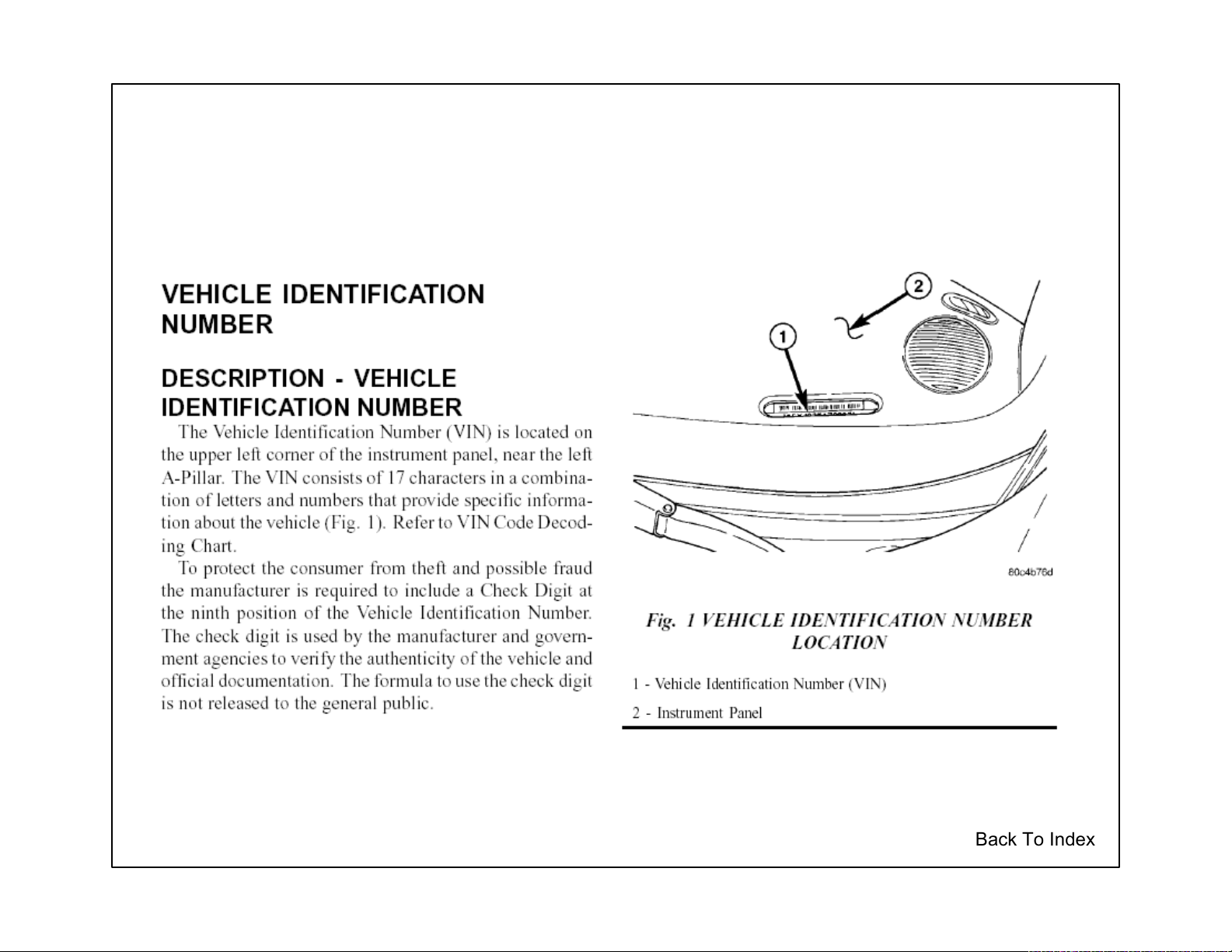
VEHICLE IDENTIFICATION NUMBER
Back To Index
Page 31

Corrosion Protection
Factory Applied Corrosion Protection
During the manufacturing of the unibody car, the manufacturer applies "corrosion protection" using specialized
manufacturing processes. This system is not duplicated in the collision repair body shop. However, the body shop still
has a responsibility to apply corrosion protection to the unibody vehicle. So, the collision repair shop must use
alternative materials to do the corrosion protection job after the repair.
This corrosion protection is required regardless of the environment and weather conditions the vehicle will be operated
in. Corrosion protection is as important in the desert as it is at the seaside. Corrosion damage can literally destroy the
structural integrity of a unibody vehicle from within. Many corrosion protection systems are destroyed during collision
repair operations. Metal finishing, metal working and fatigue can cause the breakdown of many of the corrosion barriers
installed at the factory. The use of heat for stress relief and welding also destroys factory installed corrosion barriers.
These corrosion barriers and corrosion protection systems must be replaced after collision repair to ensure that the
structural integrity of the unibody will remain intact throughout its life. In the past, only vehicles with aftermarket or afterdelivery corrosion protection systems installed were serviced after collision repair to restore the corrosion protection
system.
An understanding of the types of corrosion which affect the unibody vehicles will assist in understanding why the factory
protection systems are important, how the factory protection systems consist of and how the systems' protection is
replaced after collision and electrolytic corrosion. Some of the more common types of corrosion are crevice corrosion,
pitting, galvanic corrosion, stress corrosion, cracking, fretting, and erosion corrosion. Back To Index
Page 32

Corrosion Protection
Crevice corrosion
Crevice corrosion is a form of localized attack that occurs in areas on metal surfaces exposed to the elements.
Examples include spot weld lap joints, threaded or riveted connections, gasket fittings, porous welds, valve seats.
Pitting
Pitting is the corrosion of a metal surface at points or small areas which look like a small hole in the metal.
Galvanic corrosion
Galvanic corrosion is the type that occurs when dissimilar metals are in electrical contact while immersed in an
electrolyte.
Back To Index
Page 33

Corrosion Protection
The penetration of corrosive solutions into these small areas, with widths that are typically a few thousandths of an inch,
can result in various types of failures: the metal surface may become rusty in appearance, operating components may
seize when protective coatings may have been removed from the metal surface. The coating of zinc on steel, known as
galvanized, is an example of sacrificial cathodic protection.
An example of galvanic corrosion on the automobile is a stainless steel trim molding on a painted mild steel. When the
paint becomes damaged, a galvanic corrosion cell is formed between the passive stainless steel (cathode) and the steel
(anode). The corrosion leads to what would look like a rust stain. Methods of reducing galvanic corrosion include the
use of compatible materials, minimizing of cathode-to-anode areas, the insulation of dissimilar metal contacts and the
use of thick, replaceable sections.
Stress corrosion, cracking, fretting, and erosion corrosion.
Corrosion cracking is the early cracking of metals produced by the combined action of tensile stress and a corrosive
atmosphere.
Corrosion fatigue is cracking due to the action of stresses and corrosion. Methods of reducing corrosion fatigue include
the reduction in stress and the use of coatings.
Fretting is the deterioration of a metal at contact surfaces due to the presence of a corrosive and relative motion
between the surfaces. The two metal surfaces initially are covered with an oxide film that becomes abraded during
vibration. The results are oxide particles that become corroded. During the collision repair process, the factory
protection materials become damaged from working the metals, or from the use of heat in the repair operations. If
these factory protection materials are not replaced with some similar protection material after repair, a corrosion hot
spot is formed. A corrosion hot spot is a small unprotected area surrounded by a protected area throughout the rest of
the vehicle. the hot spot effect causes rapid deterioration of the unprotected area. This deterioration takes place at a
much faster rate, sometimes 10-12 times faster than if the entire car were unprotected. The hot spot effect is created
because all the corrosive factors are channeled to the unprotected area much the same way all material flowing through
a funnel is concentrated in a small area. This hot spot effect means that corrosion failures to the unibody structure
could occur in a short period of time even in an atmosphere normally not subject to corrosion. The hot spot effect can
cause rapid deterioration of unibody structures from corrosion damage in a desert as well as seaside.
Back To Index
Page 34

Corrosion Protection
The types of materials used in rustproofing application include oil based materials, wax base materials, primers and
color coats. The most important properties of rustproofing materials are adhesion, toughness, and the resistance to the
environment. The best coating in the world is not effective unless it is present in the right place at the right time.
Corrosion Protection Information
When making the collision repair, refer to the manufacturer's information on where corrosion protection and sealants are
applied. Be sure to follow the recommendations. The application process is usually included with the material
manufacturer's information so be sure to read and understand it before proceeding with the repair.
Collision Repair Corrosion Protection Materials
The materials must provide good electrolyte barriers. The material must also be able to penetrate tiny crevices and
prevent abrasive corrosion. The material must be compatible with paint systems as many areas of the car must be
treated before paint is applied.
Materials containing silicones will cause paint conditions such as fish eyes if they are applied before the repaired vehicle
is painted. So no silicone containing material is to be used. As many of the repair areas are more accessible before
final assembly and painting, the non-silicone type materials are a must for this type of application.
When protecting an enclosed area, fog type properties for the corrosion protection material are a plus. The fog
properties make the material much less susceptible to operator error or misapplication. With a fog type material, once
the material is introduced inside of an enclosure, the fog spreads rapidly and evenly into all areas including tiny
crevices. The fog type materials do not require direct spray application to be effective. Fog type materials are also very
effective in coating over any existing rusted or corrosion damaged areas and preventing further corrosion of these
areas. This is especially important on repairs of older vehicles.
Back To Index
Page 35

Corrosion Protection
Spray Accessibility to the Repair
Being able to achieve fog spray penetration into enclosed cavities as well as open areas requires application equipment,
which includes an assortment of wands of various lengths and design.
Some areas are more effectively treated by brush application of corrosion protection material before they are
assembled. A good example of this is an inner and outer engine compartment side rail area. Brush application to the
inside of these areas as individual pieces is easy before assembly and can be followed by a light fog application to the
weld areas and the crevices formed during assembly after the rails are assembled. Brush application keeps the foreign
material from getting between welded joints during assembly yet gives good coverage to general areas with easy
application. The material selected in addition to paint compatibility features and fog application features is also an
excellent brush application material. Repaired areas, boxed in or closed in are more easily treated during assembly
using fog and brush on techniques. Care must be taken to keep the corrosion materials away from the welding areas as
welding contamination might take place. Brush-on applications are used before welding and fog in applications are
used after welding assemblies together.
Back To Index
Page 36

Corrosion Protection
Desired Characteristics of Corrosion Protection Material
1. Corrosion prevention material- The material must displace water to prevent corrosion. This can be tested by
spraying water on an open panel on the floor, then spraying the corrosion preventative material over the watered panel
and observing if the material displaces the water.
2. Creepage of material- To insure thorough and complete protection coverage, the material should have a "creep"
capability, approximately 1/4 inch per minute while drying. This assures protective penetration of pinch welds, cracks,
etc.
3. Safe material- Material should be non-combustible when dried and when wet unable to support a fire after ignition.
4. Clean-up- The material should be of a viscosity which inhibits runs or drips. Overspray on a vehicle's painted surface
should wipe off easily without solvent when wet, with solvent when dry. The material should also dry clean off clothing.
5. Guarantee/Warranty- The corrosion protection has to be done to maintain factory corrosion warranty.
Manufacturer's recommendations must be followed.
Glossary:
Abrasion Corrosion - Rubbing or hitting of one material by another
Corrosion Protection - Material applied to deter corrosion (oxidation)
Crevice Corrosion - Oxidation when two metals are joined
Electrolytic Corrosion - Electrical action taking place between two materials in the presence of an electrolyte (liquid)
Fogging - Applying material in a mist form
Fretting - Deterioration of metal at contact surfaces due to motion and corrosive elements
Galvanic Corrosion - Electrical action (electrolysis) between two dissimilar metals in the presence of electrolyte (liquid)
Hot Spot - An unprotected area subject to corrosion
Pitting Corrosion - Corrosion on a surface the results in a small "specks" or "pinholes"
Stress of Fatigue, Cracking Corrosion - Cracking due to stress and atmospheric elements
Back To Index
Page 37

Back To Index
Page 38

247
250
329
013
274
133
018
015
190
026
117
193
073
007
039
092
172
220
055
Rt. Only
254
166
010
MODULE 49
115
223
032
031
226
224
172
176
041
041
113
MODULE 58
MODULE 55
277
277
256
236
271
053
023
051
MODULE 23
161
066
034
MODULE 7
233
161
Rt. Only
017
181
064
054
211
189
058
038
067
MODULE 66
159
245
MODULE 70
MODULE 35
025
025
009
261
004
MODULE 8
035
033
090
(4)
049
080
MODULE 54
160
076
271
012
154
110
206
206
146
146
157
212
062
027
063
MODULE 9
036
044
157
CHRYSLER 300/DODGE MAGNUM
COMPONENT CHART
238
078
056
029
178
239
198
228
228
087
086
069
065
065
215
27
2
(8)
086
069
222
085
022
252
087
072
222
191
235
098
MODULE 26
200
184
125
255
102
103
155
173
296
165
094
094
191
MODULE 33
207
MODULE 37
Left Side
141
132
149
218
015
LX BODY COMPONENT CHART MATERIAL KEY
High Strength
High Strength
High Strength
Mild Steel
Bake
MODULE 81
129
PURPLE
ORANG
GREEN
186
144
RED
GRAY
149
219
MODULE 61
145
134
Aluminum
Glass
Plastic
Dual Phase
MODULE 25
291
MODULE 31
LASTLAST
LAST
LAST
167
106
105
164
BLUE
CLEAR
YELLOW
TURQUOISE
298
068
278
070
MODULE 16
123
081
079
281
281
282
168
269
168
096
243
152
091
278
MODULE 27
121
133
152
MODULE 30
MODULE 41
206
126
283
283
114
284
199
183
281
077
MODULE 80
142
137
179
242
126
180
179
107
107
143
124
082
244
244
072
089
MODULE 51
299
156
101
MODULE 45
285
285
214
214
112
MODULE 79
280
140
188
148
290
119
118
128
139
Note: To read numbers enlarge art to 200%. Back To Index
Page 39

Welded Panel Replacement
CHRYSLER 300, 300C,
300 Touring
and
DODGE MAGNUM
The basic parts of the body structure are the welded panels. This section contains a brief description of the placement of some of the panels and
their weld locations.
Note: To ensure the strongest, most durable and cleanest welds possible, perform testing before and during all weld procedures. Always
follow American Weld Society specifications and procedures.
Note: Diagrams do not show all of the parts.
Explanation of Manual Contents...........
Front Floor............................................
Front Ladder.........................................
Engine Box...........................................
RR Floor & Ladder................................
Misc. Body............................................
Underbody-48.......................................
BSA-48.................................................
BSA-49.................................................
Front Door............................................
RR Door................................................
Liftgate..................................................
Dash/Cowl............................................
Frt Ladder,Rails, & Wheelhouse............
Engine Box Ass'y...................................
RR Ladder Ass'y....................................
RR Ladder & Floor Ass'y........................
Underbody Framing Ass'y.......................
Underbody Complete..............................
BSA Outer-48 Ass'y................................
Framed BIW-48 Ass'y.............................
Framed Full BIW-48 Ass'y......................
BSA Outer-49 Ass'y................................
Framed BIW-49 Ass'y.............................
Framed Full BIW-49 Ass'y
..................
Back To Index
Page 40

Explanation of Welding/Sealer Information
The major construction of a unibody vehicle consists of welded panels that create the supporting structure for all
componets and assemblies of the vehicle. Here are some examples for replacement of these parts.
Certain body components must use sealers to ensure proper assembly. Be sure to check the Body Sealing Locations
and Structural Adhesive Sections for location and sealer type.
SEALER LEGEND
Thumbgrade Sealer
Pumpable Sealer
Hidden Sealer
Non Structural Expand Foam
The welded componets are indicated
by using the designations given in
the illustration below: For example,
"AB to AA" indicates that component
"AB" and component "AA" shown in
this illustration are welded together.
1. AB TO AA 5/SD S/WELD
2. AC TO AA 3/SD S/WELD
Part I.D.
AC= Fender Bracket
Part I.D.
(AB TO AA)
AB= Fender Bracket
AA= Fender
Weld Attachment Location (AB TO AA)
5 Standard Spot Welds (5/SD S/WELD)
Part I.D.
(AC TO AA)
AA= Fender
Part Assembly I.D.
(Part Number 9803)
Weld Number I.D.
14 = Weld I.D.
R = right side
Back To Index
Page 41

PARTS IDENTIFICATION LEGEND, OVERVIEW 2
AA EXTENSION - TUNNEL - AH CROSSMEMBER - FRT SEAT FRT LT AB REINF - TUNNEL - AJ EXTENSION - RAIL FRT RT AC PANEL - FRT FLOOR PAN TUNNEL CTR - AK REINF - RAIL TO TUNNEL RT AD PANEL - FRT FLOOR PAN RT - AK REINF - RAIL TO TUNNEL LT AD PANEL - FRT FLOOR PAN LT - AL BRACKET - TRANS MOUNTING RT AE CROSSMEMBER - FRT SEAT RR RT - AL BRACKET - TRANS MOUNTING LT AE CROSSMEMBER - FRT SEAT RR LT - AM STUD.WELD/EXTERNAL - HEADER.PT.SPECIAL - HEAT
SHIELD ATTACH
AF STUD PLATE - CTR TUNNEL BRACE RT - AN STUD.WELD/INTERNAL - HEADER.PT.NO.FIN.ROUND -
STUD PLATE ATTACH
AF STUD PLATE - CTR TUNNEL BRACE LT - AP REINF - I/P BRACKET RT AG BRACKET - CTR BEARING MOUNTING RT - AP REINF - I/P BRACKET LT AG BRACKET - CTR BEARING MOUNTING LT - AR NUT/WELD.HEX - NO.FIN - I/P ATTACH
AH CROSSMEMBER - FRT SEAT FRT RT -
Back To Index
Page 42

1. AB TO AA 33 S/WELD
Back To Index
Page 43

2. AB TO AA 2 S/WELD
3. AC TO AB 27 S/WELD
Back To Index
Page 44

4. AE TO AD TO AC 2 S/WELD
5. AE TO AC 6 S/WELD
6. AE TO AD 17 S/WELD
Back To Index
Page 45

7. AG TO AF 22 S/WELD
8. AE TO AD TO AC 2 S/WELD
9. AE TO AC 6 S/WELD
Back To Index
Page 46

10. AG TO AE TO AC 3 S/WELD
11. AG TO AC 3 S/WELD
12. AF TO AD 2 S/WELD
13. AF TO AE TO AD 4 S/WELD
Back To Index
Page 47

14. AF TO AE TO AD 4 S/WELD
15. AG TO AE TO AC 3 S/WELD
16. AG TO AC TO AB 2 S/WELD
17. AG TO AC 1 S/WELD
18. AF TO AD 2 S/WELD
Back To Index
Page 48

19. AC TO AA 19 S/WELD
20. AD TO AC TO AA 1 S/WELD
Back To Index
Page 49

21. AH TO AA 8 S/WELD
22. AH TO AD 10 S/WELD
23. AH TO AD TO AA 1 S/WELD
Back To Index
Page 50

24. AH TO AA 4 S/WELD
25. AH TO AD TO AA 1 S/WELD
26. AH TO AD 11 S/WELD
Back To Index
Page 51

27. AH TO AD TO AA 1 S/WELD
28. AH TO AA 5 S/WELD
29. AH TO AD 10 S/WELD
Back To Index
Page 52

30. AH TO AD 12 S/WELD
31. AH TO AA 4 S/WELD
32. AH TO AD TO AA 1 S/WELD
Back To Index
Page 53

33. AJ TO AH TO AD 1 S/WELD
34. AJ TO AD 14 S/WELD
35. AJ TO AH 2 S/WELD
Back To Index
Page 54

36. AK TO AD TO AA 5 S/WELD
37. AJ TO AD 6 S/WELD
38. AK TO AD 8 S/WELD
Back To Index
Page 55

39. AJ TO AH 3 S/WELD
40. AJ TO AD 15 S/WELD
41. AK TO AJ TO AD 6 S/WELD
Back To Index
Page 56

42. AK TO AD 14 S/WELD
43. AL TO AK TO AD 5 S/WELD
Back To Index
Page 57

44. AF TO AD TO AC 3 S/WELD
45. AD TO AA 10 S/WELD
46. AD TO AC 10 S/WELD
Back To Index
Page 58

47. AD TO AA 14 S/WELD
48. AF TO AD TO AC 3 S/WELD
49. AD TO AC 11 S/WELD
50. AD TO AC TO AA 1 S/WELD
Back To Index
Page 59

51. AL TO AA 17R 9L S/WELD
52. AL TO AD TO AA 2 S/WELD
53. AL TO AD 7 S/WELD
Back To Index
Page 60

54. AM TO AA 2 PROJ WELD
55. AM TO AC 2 PROJ WELD
56. AM TO AD 7 PROJ WELD
Back To Index
Page 61

57. AM TO AD 9 PROJ WELD
58. AM TO AA 1 PROJ WELD
59. AM TO AC 2 PROJ WELD
Back To Index
Page 62

Back To Index
Page 63

PARTS IDENTIFICATION LEGEND, OVERVIEW 3
AA PANEL - TOEBOARD CROSSMEMBER - AH BRACKET - HEADLAMP MOUNTING LT AB REINF - TOEBOARD CROSSMEMBER INR RT - AJ BRACKET - ENGINE CRADLE MOUNTING LWR FRT RT AB REINF - TOEBOARD CROSSMEMBER INR LT - AJ BRACKET - ENGINE CRADLE MOUNTING LWR FRT LT AC PANEL - EXTENSION FRT RAIL OTR RT - AK BRACKET - ENGINE CRADLE MOUNTING UPR FRT RT AC PANEL - EXTENSION FRT RAIL OTR LT AK BRACKET - ENGINE CRADLE MOUNTING UPR FRT LT AD PANEL - EXTENSION FRT RAIL INR RT AL TAPPING PLATE - FLOATING AD PANEL - EXTENSION FRT RAIL INR LT - AM NUT/WELD.SQ - SQUARE - FRT SIDE RAIL ASSY LT
AE BRACKET - ENGINE CRADLE MOUNTING UPR RR RT - AN STUD.WELD/EXTERNAL - HEADER.PT.SPECIAL - DEAD
AE BRACKET - ENGINE CRADLE MOUNTING UPR RR LT - PEDAL TRIM PNL ATTACH
AF PANEL - FRT SIDE RAIL INR RT - AP PANEL - SHOCK TOWER MOUNTING FRT RT AG REINF - FRT SIDE RAIL BUMPER MOUNTING RT - AR BRACKET - FRT SUSP UPR CONTROL ARM RT AG REINF - FRT SIDE RAIL BUMPER MOUNTING LT - AT REINF - FRT SHOCK TOWER RT AH BRACKET - HEADLAMP MOUNTING RT - AT REINF - SHOCK TOWER TO LOAD BEAM RT - SHOCK
TOWER RH
AU PANEL - FRT WHEELHOUSE FRT RT AV PANEL - FRT WHEELHOUSE RR RT -
AX CHARTONLY-NONTORQUE HEADER.PT.LOCK.FEAT.
SPECIAL - SHOCK TOWER GROUND
AY NUT/WELD.HEX - NO.FIN - FRT STRUT TWR TO TWR
BEAM ATTACH
AZ BRACKET - RETAINER ENGINE CRADLE TAPPING PLATE
FRT BA REINF - RAIL FRT - FRT RAIL
Back To Index
Page 64

Back To Index
Page 65

2. AE TO AC 1/SD S/WELD
3. AE TO AD TO AC 2/SD S/WELD
4. AD TO AC 11/SD S/WELD
5. AK TO AJ 4/SD S/WELD
6. AG TO AJ 1/SD S/WELD
7. AK TO AJ TO AG 1/SD S/WELD
Back To Index
Page 66

8. AE TO AC TO AF 1/SD S/WELD
9. AE TO AC 7/SD S/WELD
Back To Index
Page 67

10. AF TO AD 5/SD S/WELD
11. AF TP AE 6/SD S/WELD
12. AF TO AE TO AD 1/SD S/WELD
13. AE TO AD 2/SD S/WELD
Back To Index
Page 68

14. AH TO AF 5/SD S/WELD
15. AG TO AF 6/SD S/WELD
Back To Index
Page 69

16. AK TO AJ TO AF 8/SD S/WELD
17. AL TO AF 2/SD S/WELD
18. AK TO AJ 5/SD S/WELD
Back To Index
Page 70

19. AM TO AG 4/SD PROJ WELD
20. AM TO AH 1/SD PROJ WELD
21. AN TO AF 1/SD PROJ WELD
Back To Index
Page 71

22. AR TO AP 22R/23L S/WELD
Back To Index
Page 72

23. AT TO AP 13R/14L S/WELD
24. AS TO AR 4R/2L S/WELD
25. AS TO AP 7/SD S/WELD
Back To Index
Page 73

26. AU TO AP 9/SD S/WELD
27. AW TO AP 8/SD S/WELD
Back To Index
Page 74

28. AW TO AU 2 PROJ WELD
29. AX TO AP 2/SD PROJ WELD
30. AX TO AU 1 PROJ WELD
31. AY TO AP 2/SD PROJ WELD
Back To Index
Page 75

32. BA TO AE 2/SD S/WELD
33. AZ TO AE 7SD PROJ WELD
34. AZ TO AK 7/SD PROJ WELD
Back To Index
Page 76

PARTS IDENTIFICATION LEGEND, OVERVIEW 4
AA PANEL - LOAD PATH BEAM UPR INR RT AA PANEL - LOAD PATH BEAM UPR INR LT AB BRACKET - HEADLAMP MOUNTING RT AB BRACKET - HEADLAMP MOUNTING LT AC BRACKET - WIPER MODULE MTG AD NUT/WELD.HEX - NO.FIN - BRKT TO MODULE
AE STUD.WELD/INTERNAL - NO.FIN.PILOT.PT - UPR BRAKE PEDAL ATT
AF REINF - BRAKE BOOSTER -
Back To Index
Page 77

1. AB TO AA 4/SD S/WELDS
Back To Index
Page 78

2. AC TO AD 1 PROJ WELD
Back To Index
Page 79

3. AE TO AF 1 PROJ WELD
4. AE TO AF 1 PROJ WELD
Back To Index
Page 80

Back To Index
Page 81

PARTS IDENTIFICATION LEGEND, OVERVIEW 5
AA RAIL - RR INR RT - AM STUD.WELD/INTERNAL - HEADER.PT.NO.FIN.PF- SAFETY
AA RAIL - RR INR LT - CENTER SEAT BELT RETRACTOR ATT
AB REINF - RR RAIL INR RR RT - AN CROSSMEMBER - RR SUSPENSION FRT AB REINF - RR RAIL INR RR LT - AP TAPPING PLATE AC NUT/WELD.SQ - SQUARE - RAIL ATTACH AR EXTENSION - CROSSMEMBER END SUPPORT RT AD TAPPING PLATE - SEAT BELT RETRACTOR AR EXTENSION - CROSSMEMBER END SUPPORT LT -
ANCHOR RR CTR - AS REINF - CROSSMEMBER RR SUSPENSION MOUNTING RT AE RAIL - RR OTR RT - AS REINF - CROSSMEMBER RR SUSPENSION MOUNTING LT AE RAIL - RR OTR LT - AT BRACKET - RETAINER ENGINE CRADLE TAPPING PLATE FRT AF BRACKET ASSY - CRADLE RT - AU NUT/WELD.SQ - SQUARE - BATTERY TRAY ATTACH
AF BRACKET ASSY - CRADLE LT - AV PAN - RR FLOOR AG TAPPING PLATE - SEAT BELT RETRACTOR AW REINF - SPARE TIRE HOLD-DOWN -
ANCHOR RR CTR - AX GUSSET - ISO FIX AH REINF - RR RAIL OTR RT - AY STUD.WELD/INTERNAL - HEADER.PT.NO.FIN.PF-SAFETY - CTR
AH REINF - RR RAIL OTR LT - RR RETRACTOR ATTACH
AJ BRACKET - CRADLE ATTACHING RT - AZ CROSSMEMBER - ISO FIX AJ BRACKET - CRADLE ATTACHING LT - BA WIRE - ISO FIX - RIGHT
AK BRACKET - RETAINER ENGINE CRADLE BA WIRE - ISO FIX - LEFT
TAPPING PLATE FRT - BB WIRE - ISO FIX - CENTER
AL REINF - SEAT BELT ANCHOR RR INBOARD -
Back To Index
Page 82

1. AB TO AA 16R & 12L S/WELDS
Back To Index
Page 83

2. AB TO AA 16R & 9L S/WELDS
3. AC TO AA 2 PROJ WELDS
Back To Index
Page 84

4. AB TO AA 8L S/WELDS
5. AD TO AB 4L S/WELDS
Back To Index
Page 85

6. AF TO AE 7/SD S/WELDS
7. AG TO AE 2/SD S/WELDS
Back To Index
Page 86

8. AH TO AE 24/SD S/WELDS
Back To Index
Page 87

9. AH TO AE 5/SD S/WELDS
Back To Index
Page 88

10. AK TO AJ 4/SD S/WELDS
11. AM TO AL 1 PROJ WELD
Back To Index
Page 89

12. AP TO AN 2/SD S/WELDS
13. AS TO AR 6/SD S/WELDS
Back To Index
Page 90

14. AR TO AN 9/SD S/WELDS
15. AT TO AS 4/SD S/WELDS
Back To Index
Page 91

16. AU TO AV 2 PROJ WELDS
17. AW TO AV 10 S/WELDS
Back To Index
Page 92

18. AY TO AX 4/SD PROJ WELDS
19. AZ TO AX 4/SD S/WELDS
20. BA TO AZ 4 FCAW WELDS
Back To Index
Page 93

21. BB TO AX 2/SD FCAW WELDS
22. BC TO AZ 16 FCAW WELDS
Back To Index
Page 94

PARTS INDENTIFICATION LEGEND, OVERVIEW 6
AA PANEL - ROOF SUNROOF - AH EXTENSION - IMPACT BEAM FRT DOOR RR RT AB PANEL - ROOF OTR - AH EXTENSION - IMPACT BEAM FRT DOOR RR LT AC PANEL - ROOF SUNROOF - AJ EXTENSION - RR DOOR IMPACT BAR RR RT AD REINF - SUNROOF - AJ EXTENSION - RR DOOR IMPACT BAR RR LT AE BAR - IMPACT FRT DOOR RT - AK EXTENSION - RR DOOR IMPACT BAR FRT RT AE BAR - IMPACT FRT DOOR LT - AK EXTENSION - RR DOOR IMPACT BAR FRT LT AF BAR - IMPACT RR DOOR RT - AL REINF - PLATE AF BAR - IMPACT RR DOOR LT - AL REINF - PLATE - ROOF RACK REAR
AG EXTENSION - IMPACT BEAM FRT DOOR FRT RT - AM NUT/WELD.HEX - HEX.DRIVE.SPECIAL AG EXTENSION - IMPACT BEAM FRT DOOR FRT LT - SUNROOF MODULE
Back To Index
Page 95

1. AH TO AE 2 GMAW WELD
2. AG TO AE 2 GMAW WELD
3. AJ TO AE 2 GMAW WELD
4. AK TO AF 2 GMAW WELD
Back To Index
Page 96

5. AD TO AA 30 S/WELD
Back To Index
Page 97

6. AD TO AC 28 S/WELD
Back To Index
Page 98

7. AL TO AA 8 S/WELD
Back To Index
Page 99

8. AL TO AB 8 S/WELD
Back To Index
Page 100

9. AM TO AD 6 PROJ WELD
Back To Index
 Loading...