

Page 1

Reprinted
August, 2006
INTRODUCTION
CHRYSLER 45RFE
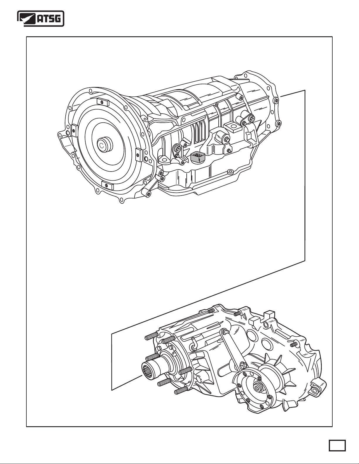
Beginning at the start of production for the 1999 model year Chrysler Corporation has introduced a brand new
rear wheel drive transmission for the 99 Jeep Grand Cherokee with the 4.7L engine, and scheduled for the Ram
Pick-up for the 2000 model year. This is the first completely new rear wheel drive automatic transmission from
Chrysler in more than thirty years. The 45RFE designation tells us that this new unit has 4 forward speeds, a
relative torque rating of 5, is for Rear drive vehicles and is Fully Electronic controlled. Refer to Figure 1. The
545RFE was introduced in 2003 in 3.7 and 5.7 engines. There are few differences in the components between
the 45RFE and the 545RFE, although the main difference is the addition of a fifth ratio, which is electronically
controlled.
No part of any ATSG publication may be reproduced, stored in any retrieval system or transmitted in any form or
by any means, including but not limited to electronic, mechanical, photocopying, recording or otherwise,
without written permission of Automatic Transmission Service Group. This includes all text illustrations,
tables and charts.
The information and part numbers contained in this booklet have
been carefully compiled from industry sources known for their
reliability, but ATSG does not guarantee its accuracy.
DALE ENGLAND
FIELD SERVICE CONSULTANT
PETER LUBAN
TECHNICAL CONSULTANT
JON GLATSTEIN
TECHNICAL CONSULTANT
ROLAND ALVAREZ
TECHNICAL CONSULTANT
GERALD CAMPBELL
TECHNICAL CONSULTANT
GABE DE LOS REYES
TECHNICAL CONSULTANT
Copyright © ATSG 2009
WAYNE COLONNA
PRESIDENT
JIM DIAL
TECHNICAL CONSULTANT
ED KRUSE
TECHNICAL CONSULTANT
GREGORY LIPNICK
TECHNICAL CONSULTANT
DAVID CHALKER
TECHNICAL CONSULTANT
GREG CATANZARO
TECHNICAL CONSULTANT
RICHARD GRAHAM
TECHNICAL CONSULTANT
AUTOMATIC TRANSMISSION SERVICE GROUP
18635 S.W. 107 AVENUE
MIAMI, FLORIDA 33157
(305) 670-4161
1
Page 2

CH RYS LER 4 5R FE
CH RYS LER 5 45 RFE
INDEX
CLUTCH APPLICATION CHART ......................................................................................................................
SOLENOID ON/OFF CHART ...............................................................................................................................
CASE CONNECTOR AND TCM PIN CAVITY IDENTIFICATION ...............................................................
WIRING SCHEMATIC ..........................................................................................................................................
CONTROL RELAY AND FUSE LOCATIONS ...................................................................................................
TRS/SOLENOID BODY TESTS ...........................................................................................................................
OBDII DIAGNOSTIC TROUBLE CODE IDENTIFICATION .........................................................................
OIL PASSAGE IDENTIFICATION ......................................................................................................................
LINE PRESSURE TESTING .................................................................................................................................
GENERAL TRANSMISSION OPERATION INFORMATION ........................................................................
TRANSMISSION DISASSEMBLY PROCEDURE .............................................................................................
COMPONENT REBUILD PROCESS
TRANSMISSION CASE ASSEMBLY ..............................................................................................................
LOW/REVERSE CLUTCH HOUSING ASSEMBLY .....................................................................................
2-4 CLUTCH RETAINER ASSEMBLY ...........................................................................................................
GEAR TRAIN COMPONENTS ........................................................................................................................
INPUT CLUTCH HOUSING ASSEMBLY ......................................................................................................
INPUT CLUTCH HOUSING SNAP RING IDENTIFICATION ...................................................................
OIL PUMP ASSEMBLY INCLUDING VALVES ............................................................................................
VALVE BODY ASSEMBLY ...............................................................................................................................
TRANSMISSION FINAL ASSEMBLY PROCEDURE ......................................................................................
CHECKING FRONT END PLAY .........................................................................................................................
AIR PRESSURE TESTS ........................................................................................................................................
END PLAY SPECIFICATIONS ............................................................................................................................
FLUID SPECIFICATIONS ....................................................................................................................................
TORQUE SPECIFICATIONS AND BOLT IDENTIFICATION .......................................................................
EXPLODED ILLUSTRATIONS OF INTERNAL PARTS .................................................................................
THRUST BEARING CHART ................................................................................................................................
SPECIAL TOOLS ...................................................................................................................................................
545RFE DIAGNOSTIC TROUBLE CODES..........................................................................................................
NGC MODELS WIRING SCHEMATIC.................................................................................................................
NGC CONNECTOR I.D. AND LOCATIONS............................................................................................................
NGC "C4" CONNECTOR TERMINAL I.D.............................................................................................................
SOLENOID PACK UPDATE TSB.....................................................................................,......................................
4
5
11
13
14
18
20
22
30
31
32
42
44
50
53
54
56
65
73
83
89
91
96
96
97
98
108
109
112
113
114
115
116
CAUTION: ATSG service manuals are intended for use by professional,
qualified technicians. Attempting repairs or service without the proper
training, tools and equipment could cause injury to you or others and damage
to the vehicle that may cause it not to operate properly.
AUTOMATIC TRANSMISSION SERVICE GROUP
18635 S.W. 107 AVENUE
MIAMI, FLORIDA 33157
(305) 670-4161
Copyright © ATSG 2009 June 2009
2
Page 3
Technical Service Information
45/545RFE TRANSMISSION
FOUND BEHIND 4.7L ENGINE FOR 1999
IN 3.7 LIBERTY AND 5.7 DODGE TRUCKS
4 = Four Forward Speeds
5 = Five Forward Speeds
5/45 = Relative Torque Capacity
R = Rear Wheel Drive
FE = Fully Electronic
Figure 1
AUTOMATIC TRANSMISSION SERVICE GROUP
Copyright © 2009 ATSG
3
Page 4
SELECTOR
POSITION
PARK ON
REVERSE
NEUTRAL
OD-1ST
OD-2ND
2ND PRIME
OD-3RD
OD-4TH
OD-5TH**
OD-LIMP
Technical Service Information
45/545RFE CLUTCH APPLICATION CHART
LO/REV
CLUTCHUDCLUTCH
ON ON 3.00:1
ON
ON
*
ON
ON
ON ON
ON ON
ON
SECOND
CLUTCHODCLUTCH
ON
ON
ON
ON
ON
FOURTH
CLUTCH
ON
REVERSE
CLUTCH
LOW OVERRUN
CLUTCH
HOLD
GEAR
RATIO
3.00:1
1.67:1
1.50:1
1.00:1
0.75:1
0.67:1
1.00:1
(2)-1ST
(2)-2ND
(2)-LIMP
(1)-1ST
L/R Clutch is on only with the output shaft speed below 150 RPM.
*
545RFE Only
**
ON
*
ON
*
Underdrive
Clutch
ON
ON
ON
ON
ON
ON
Overdrive
Clutch
Reverse
Clutch
Fourth
Clutch
Second
Clutch
HOLD
HOLD
Low/Reverse
Clutch
3.00:1
1.67:1
1.67:1
3.00:1
Low Roller
Clutch
Copyright © 2009 ATSG
Figure 2
4
AUTOMATIC TRANSMISSION SERVICE GROUP
Page 5
Technical Service Information
MECHANICAL OPERATION
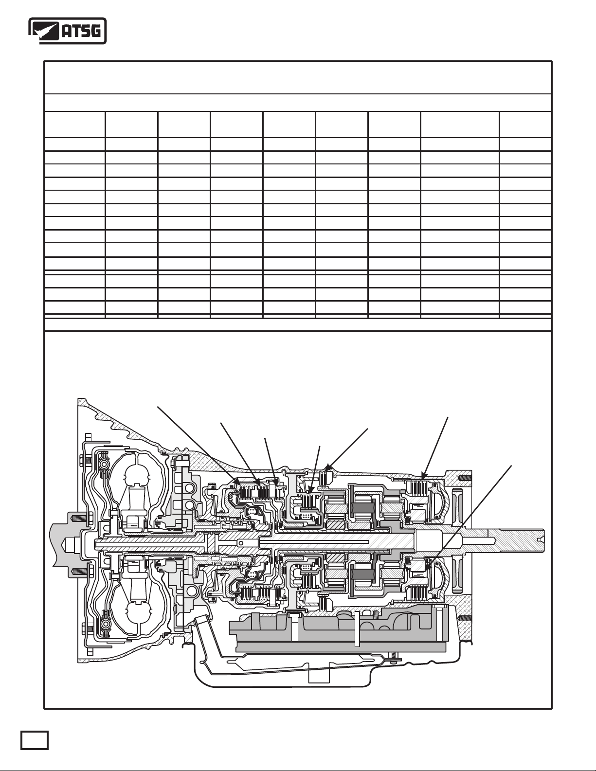
The operation of the 45RFE is very similar to the Chrysler 41TE (A604) and 42LE (A606) transaxles that you
are already familiar with. The 45/545RFE has no internal bands, but uses several different clutch assemblies
instead. The Input Clutch Housing retains the underdrive clutch, overdrive clutch and the reverse clutch and is
set up almost identical to the 41TE transaxle, except much larger. The 45/545RFE also contains seperate
holding clutches, such as the 2nd clutch, 4th clutch and the low/reverse clutch. This unit also uses one
overrunning or freewheel device called the low overrun clutch.
To achieve its different gear ratios, the 45/545RFE applies different combinations of two clutch packs at a time,
as shown in Figure 2. In Park and Neutral, only the low/reverse clutch is applied. Notice also that a unique
characteristic of the 45/545RFE is its alternate 2nd gear ratio, or "2nd prime" as it is known. The 2nd prime is
enabled only during kickdown shifts above certain speeds, that enhances vehicle performance by allowing for a
higher gear ratio passing gear at highway speeds. Refer to the chart in Figure 2 for the clutches that are applied
for each shift lever position.
Another feature of this unit is the three planetary gear sets, as shown in Figure 2, which is one more than you are
used to seeing in a Chrysler unit. These planetary gear sets provide a deeper 1st and reverse ratio and does not
need a seperate overdrive unit. All gear ratios are also shown in the chart in Figure 2.
SELECTOR
POSITION
P/N
Under 8
P/N
Over 8
REVERSE
REV-Block
OD-1ST
OD-2ND
2ND PRIME
OD-3RD
OD-4TH
OD-5TH
(1)-1ST Or
Autostick
FAILSAFE
SOLENOID CHART
N.V. N.V. N.V. N.V.N.A. N.A.
LR/CC
SOLENOIDUDSOLENOIDODSOLENOID
ON
ON
*
*
*
*
ON
OFF OFF OFF OFF OFF OFF OFF
ON
ON
ON
ON
ON
ON
2nd CLUT
SOLENOID
ON
ON
4th CLUT
SOLENOID
ON
ON
Multi-Select
SOLENOID
OFF
ON
ON
ON
ON
ON
ON
Variable Force
SOLENOID
Modulating
Modulating
Modulating
Modulating
Modulating
Modulating
Modulating
Modulating
Modulating
Modulating
Modulating
Modulating (EMCC) if the Converter Clutch has been signaled.
*
N.V.= Normally Vented
N.A.= Normally Applied
Figure 3
AUTOMATIC TRANSMISSION SERVICE GROUP
Copyright © 2009 ATSG
5
Page 6

Technical Service Information
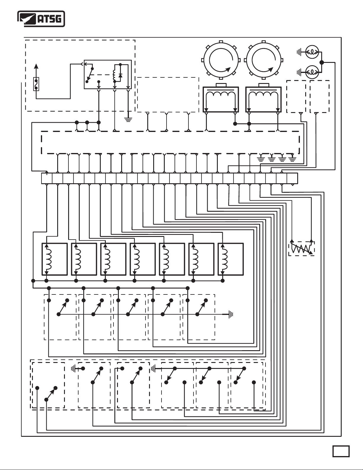
ELECTRICAL OPERATION
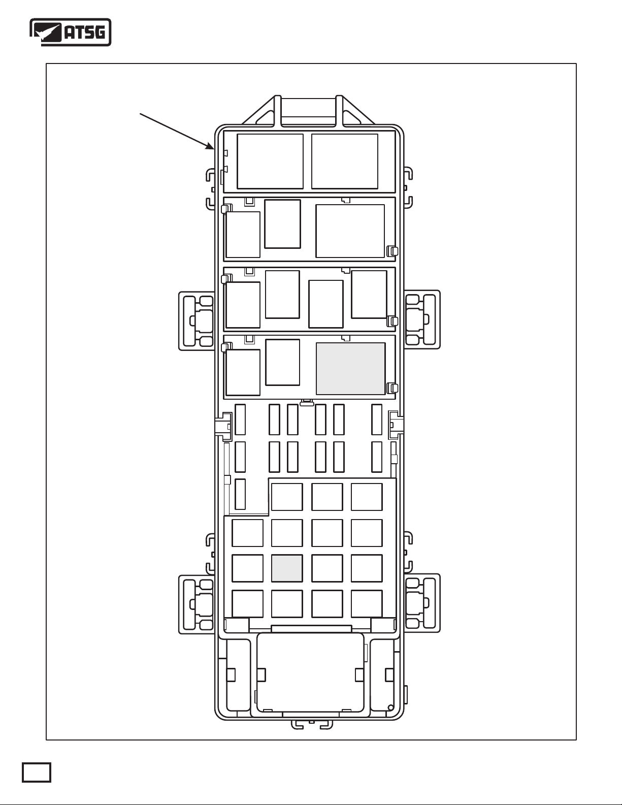
The Transmission Control Module (TCM) or New Generation Controller (NGC) controls all of the
transmission functions and is located in the engine compartment, as shown in Figure 5. The Powertrain Control
Module (PCM) does not control the transmission, other than models that have the NGC, as the Transmission
control is combined with the PCM. The electronic components of the 45/545RFE transmission consist of
various sensors and switches as input information to the TCM, that the TCM uses to determine the appropriate
gear ratio and shift schedule points. There is also the associated wiring, fuses, relays, connectors, splices and
grounds for the transmission to function as designed. A complete transmission wiring schematic has been
provided for you in Figure 9.
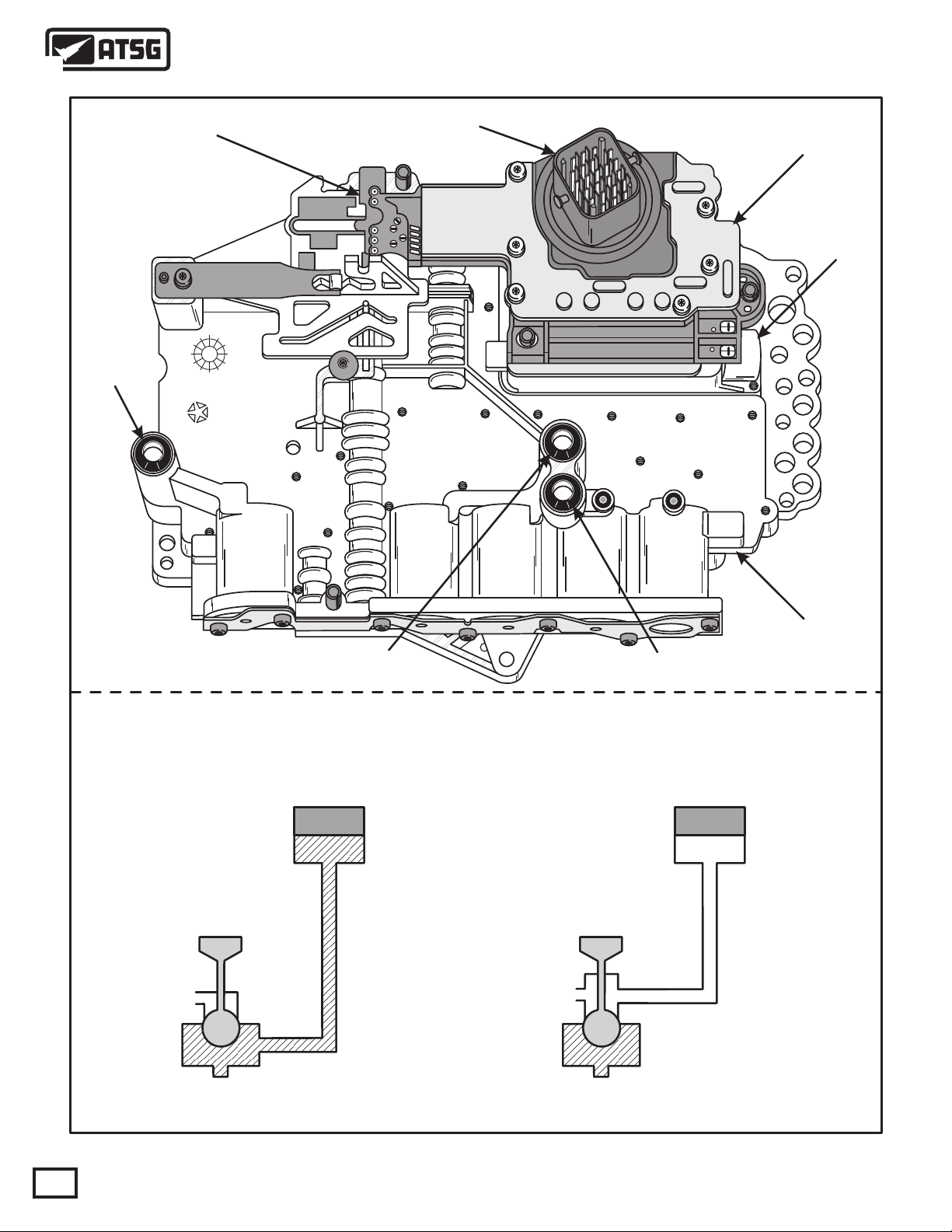
The final output from the TCM is to the six shift solenoids and the line pressure control solenoid located in the
Solenoid Pack/Transmission Range Sensor assembly and bolted on the valve body as shown in Figure 4. The
solenoids in this transmission are unique in that some are normally vented and some are normally applied and is
illustrated in Figure 4. The TCM also communicates with other control modules, such as the PCM, currently
using the two wire CCD Bus for communication. NGC modules use PCI or CAN bus . The TCM receives power
from two sources, fused battery power to pin 56 and fused ignition switch input to pin 11, both at the 60-way
connector on the TCM. The TCM also has a ground to complete its electrical circuit. (See Figure 8). See the
NGC schematic on Page 113.
INPUTS TO THE TCM
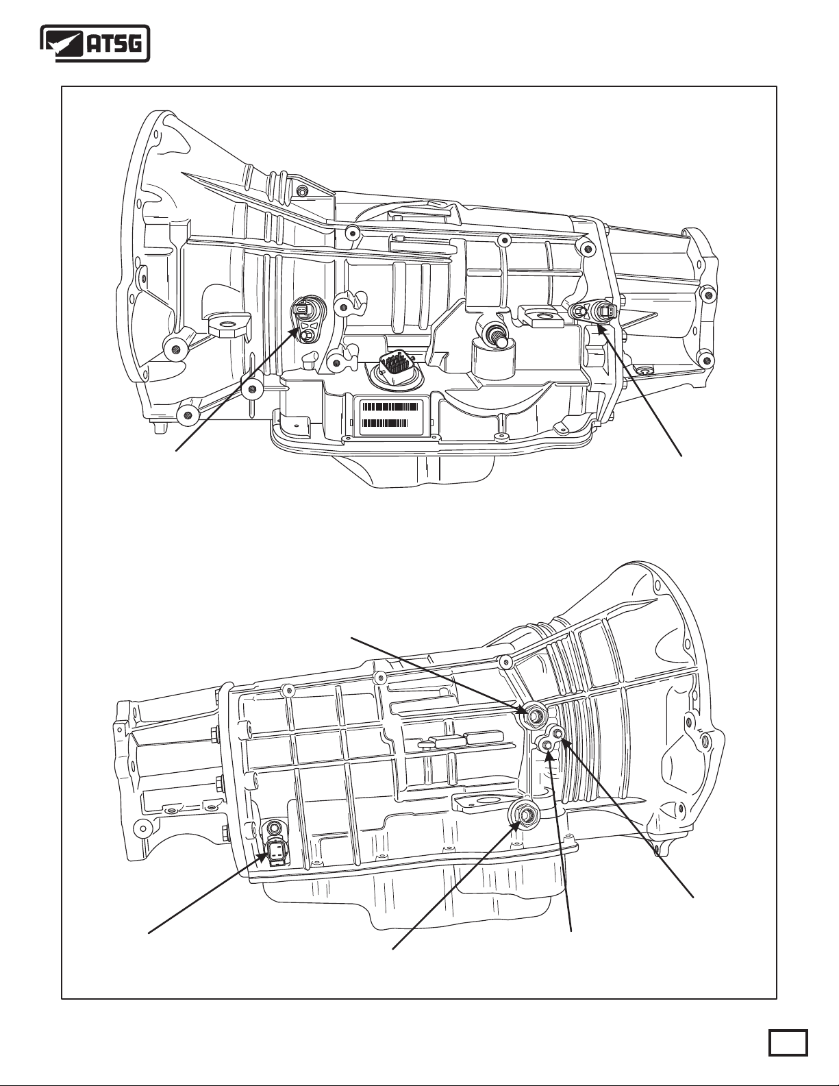
Input and Output Shaft Speed Sensors - are located on the left side of the transmission and are illustrated in
Figure 11. The input shaft speed sensor reads input shaft speed off of a tone wheel. The TCM/NGC compares
this reading with that of the output shaft speed sensor, which is also read off of a tone wheel. This comparison
provides the TCM/NGC with gear ratio information. The crankshaft position sensor supplies the TCM with
engine RPM data that is also critical to scheduling shift points.
Line Pressure Sensor - is located on the right rear of the transmission, as illustrated in Figure 11, and supplies
the TCM/NGC with line pressure information. The line pressure sensor operates much like a throttle position
sensor.
Transmission Fluid Temperature Sensor - is located in the Solenoid Pack/Transmission Range Sensor and is a
thermister that the TCM uses to moniter transmission fluid temperature.
Solenoid Pack/Transmission Range Sensor - contains several different inputs to the TCM/NGC. The TRS
contains five switches that tell the TCM/NGC, through different combinations of switch states, what position
the manual gear selector has been placed. There is also a back-up lamp switch incorporated in the TRS.
In addition to the switches above, there are five pressure switches to monitor pressure in the Low/Rev, Second
Clutch, Fourth Clutch, Underdrive Clutch and Overdrive Clutch hydraulic circuits. The primary function of
these switches is to help the TCM/NGC detect when clutch circuit hydraulic failures occur. The TCM/NGC
continuously monitors the switches for the correct states (Open or Closed) in each gear as shown in the chart in
Figure 5.
Copyright © 2009 ATSG
6
AUTOMATIC TRANSMISSION SERVICE GROUP
Page 7

Technical Service Information
ADAPTIVE LEARNING
The 45/545RFE transmission uses an "Adaptive Learning" feature which allows the TCM/NGC to modify the
clutch apply rate to maintain consistant shift quality. This is done based on the amount of wear on the friction
elements. The TCM/NGC then adjusts the duty cycle of the shift solenoids to achieve the smoothest possible
upshifts and downshifts. The TCM/NGC adjusts the "Clutch Volume Index" when a shift change takes place to
optimize clutch to clutch timing. Clutch Volume Index is described in Figure 6, along with proper clutch
volumes and clutch clearances for the 45/545RFE transmission.
OUTPUTS FROM THE TCM
Transmission Control Relay - located in the Power Distribution Center (PDC), as shown in Figure 10, and
recieves a ground signal from terminal 15 at the TCM/NGC to close the relay. Refer to the wiring schematic in
Figure 9.
Underdrive Solenoid with Pressure Switch - This solenoid is normally applied and controls oil to the UD
clutch in all 1st, 2nd, 2nd Prime and 3rd gears of the transmission.
Overdrive Solenoid with Pressure Switch - This solenoid is normally vented and controls oil to the OD clutch
in 3rd and 4th gears in the transmission.
Fourth Clutch Solenoid with Pressure Switch - This solenoid is normally vented and controls oil to the 4th
clutch in all 4th and 2nd Prime gears in the transmission.
Second Clutch Solenoid with Pressure Switch - This solenoid is normally vented and controls oil to the 2nd
clutch in all 2nd gears and Fifth (545RFE) in the transmission.
Low/Reverse Solenoid with Pressure Switch - This solenoid is normally vented and is used to apply the L/R
clutch in 1st from neutral, or coast down to 1st, and to control oil for converter clutch engagement.
Multi-Select Solenoid - The Multi-Select Solenoid is normally applied and controls the OD clutch in 3rd gear
Limp-in, 2nd clutch in Manual 2, 2nd Limp-in and the Low/Reverse clutch in reverse.
LIMP-IN MODE OPERATION
The TCM/NGC has the ability to monitor all transmission related electrical components and if it detects a
problem, takes appropriate action, and most of the time results in the TCM/NGC setting a Diagnostic Trouble
Code (DTC). Whether this results in MIL illumination, or Limp-in Mode operation, depends on the type of
DTC that was set.
If the TCM/NGC determines that transmission damage may result from the DTC type that was set, the
TCM/NGC will shut off the ground signal to the transmission control relay which will shut off all power to the
transmission and the vehicle will be in Limp-in Mode Operation.
When in Limp-in Mode Operation, with the shift lever in the "Drive" position the transmission will be in 3rd
gear, and if the shift lever is moved to "2" or "L" position the transmission will be in 2nd gear. This will allow the
driver to manually shift the transmission to Limp home.
DIAGNOSIS AND SERVICE INFORMATION
You have been provided with the 23-way case connector pin cavity identification and pin function in Figure 7,
and 60-way TCM or NGC connector pin cavity identification and pin function in Figure 8 and page115 for NGC.
A complete transmission wiring schematic is provided in Figure 9 , on page 113 for NGC. Transmission control
relay location in the power distribution center is shown in Figure 10.
Special tools that might be needed are illustrated in Figure 12, along with the identification of the pressure taps
that are available on the main valve body. Air pressure test passage identification is provided for you in Figure
13.
AUTOMATIC TRANSMISSION SERVICE GROUP
Copyright © 2009 ATSG
7
Page 8
Technical Service Information
TRANSMISSION
RANGE SENSOR
L/R Clutch
Seal
97
4799591
23-WAY
CONNECTOR
SOLENOID
PACK
PRESSURE
CONTROL
SOLENOID
2nd Clutch
TWO DIFFERENT TYPES OF SHIFT SOLENOIDS
Underdrive Solenoid
Multi-Select Solenoid
Seal
VALVE BODY
4th Clutch
Seal
Overdrive Solenoid
4th Clutch Solenoid
2nd Clutch Solenoid
Low/Reverse Solenoid
"Solenoid Off"
"Normally Applied"
"Solenoid Off"
"Normally Vented"
Copyright © 2009 ATSG
Figure 4
8
AUTOMATIC TRANSMISSION SERVICE GROUP
Page 9
Technical Service Information
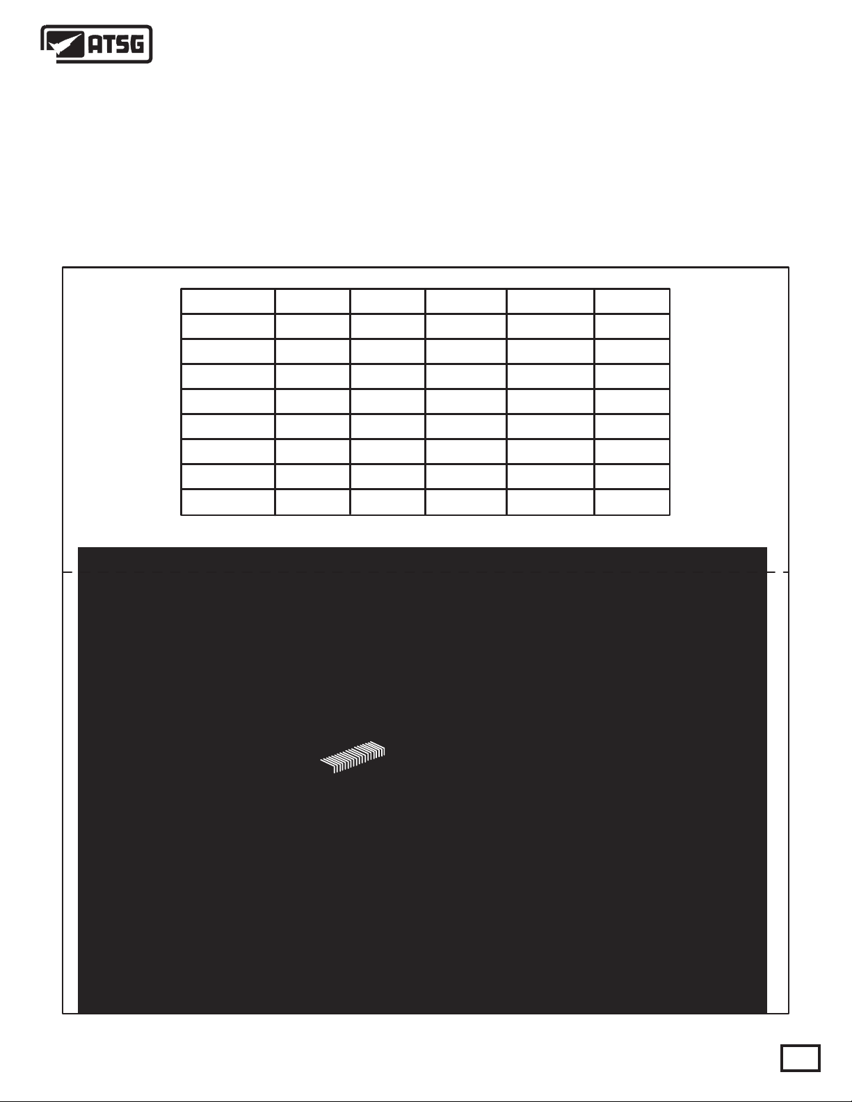
PRESSURE SWITCHES
The pressure switches are located inside the solenoid and pressure switch assembly and are only serviced by
replacing the complete assembly.
The Transmission Control Module and or New Generation Control module is located as shown below and relies
on five pressure switches to monitor pressure in the Low/Rev, 2nd Clutch, 4th Clutch, Underdrive, and
Overdrive hydraulic circuits. The primary function of these switches is to help the TCM/NGC detect when the
clutch circuit hydraulic failures occur. The switches close at 23 psi and open at 11 psi, and indicate whether or
not pressure exists. The switches are continuously monitored by the TCM/NGC for the correct states (Open or
Closed) in each gear as shown in the chart below.
SWITCH CHART
Low/Rev
2nd Clut 4th Clut Underdrive Overdrive
Park/Neut
Reverse
First
Second
2nd Prime
Third
Fourth
**Fifth
* L/R is closed if output speed is below 150 RPM in Drive and Manual 2.
L/R is open in Manual 1.
**545RFE
TRANSMISSION
CONTROL MODULE
JEEP
Closed
Open
Closed*
Open
Open
Open
Open
Open Open
Open
Open
Closed
Open
Open
Open
Open
Open
Open
Closed
Open
Closed
Open
Open
Closed
Closed
Closed
Open
Open
Open
Open
Open
Closed Closed
Open
Closed
ClosedOpen OpenOpen Closed
NGC MODULE
IS LOCATED NEAR
FIREWALL AND
HAS 4 CONNECTORS
TRANSMISSION
CONTROL MODULE
CAN BE FOUND ON
THE RADIATOR SUPPORT
ON DODGE TRUCKS
FRONT
Figure 5
AUTOMATIC TRANSMISSION SERVICE GROUP
60 WAY
CONNECTOR
Copyright © 2009 ATSG
9
Page 10
Technical Service Information
CLUTCH VOLUME INDEXES
An important function of the TCM/NGC is to monitor Clutch Volume Indexes (CVI). CVIs represent the
volume of fluid needed to compress a clutch pack properly.
The TCM/NGC monitors gear ratio changes by monitoring the Input and Output Speed Sensors. The Input
Speed Sensor sends an AC voltage signal to the TCM/NGC that represents input shaft rpm. The Output Speed
Sensor provides the TCM/NGC with output shaft speed information.
By comparing these two inputs, the TCM/NGC can determine actual gear ratio. This is important to the CVI
calculation because the TCM/NGC determines CVIs by monitoring how long it takes for a gear change to occur.
Gear ratios can be determined by using the DRB Scan Tool and reading the Input/Output Speed Sensor values in
the "Monitors" display. Gear ratio can be obtained by dividing the Input Speed Sensor value by the Output
Speed Sensor value.
For example, if the input shaft is turning at 1000 rpm and the output shaft is turning at 500 rpm, the TCM/NGC
can determine that the gear ratio is 2:1. In 3rd gear the gear ratio changes to 1:1. The gear ratio changes as
clutches are applied and released. By monitoring the length of time it takes for a gear ratio to change following a
shift request, the TCM can determine the volume of fluid used to apply or release a friction element.
The volume of transmission fluid needed to apply the friction elements are continuously updated for the
adaptive controls. As friction material wears, the volume of fluid needed to apply the friction element increases.
Certain mechanical problems within the transmission assembly such as broken return springs, out of position
snap rings, excessive clutch pack clearance, or improper assembly can cause inadequate or out-of-range CVI
readings. Also defective Input/Output Speed Sensors, wiring and poor connections may cause these same
conditions. The following chart identifies the proper CVIs, when they are monitored and updated and the
proper clutch pack clearances.
CLUTCH VOLUMES AND CLEARANCES
CLUTCH WHEN UPDATED PROPER VOLUME CLUTCH CLEARANCE
Low/Reverse
2nd Clutch
Overdrive
4th Clutch
Underdrive
Reverse
2-1 or 3-1 Downshift 82 to 134 1.14-1.91mm (.045"-.075")
3-2 Kickdown shift
2-3 Upshift
3-4 Upshift
4-3 Kickdown shift
Not Monitored Not Monitored
Figure 6
25 to 64
30 to 64
30 to 64
44 to 92
0.53-1.27mm (.021"-.050")
1.01-1.65mm (.040"-.065")
0.81-1.35mm (.032"-.053")
0.76-1.60mm (.030"-.063")
0.81-1.24mm (.032"-.049")
10
Copyright © 2009 ATSG
AUTOMATIC TRANSMISSION SERVICE GROUP
Page 11
Technical Service Information
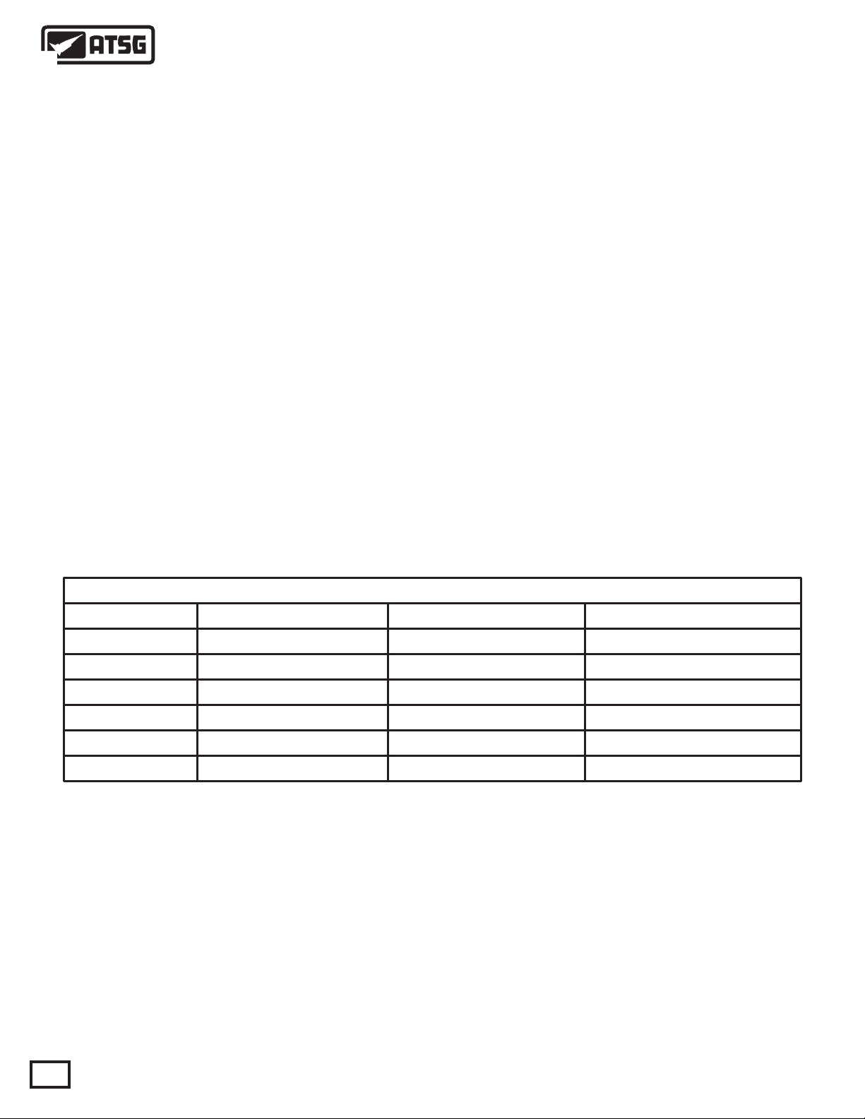
23-WAY CASE CONNECTOR PIN CAVITY IDENTIFICATION AND FUNCTION
212223
17
123
4
567
89101112
13
141516
17181920
"Front"
20
16
12
212223
81
19
15
11
7
14
13
8
9
01
5
6
2
3
4
1
Vehicle Harness Connector
PIN
CAVITY
1
2
3
4
5
6
7
8
9
10
11
12
13
WIRE
COLOR
White/Tan
Lt. Green
Brown/Yellow
White
Violet/White
Violet/Black
Brown
Violet
Lt. Green/Black
Red
Dk. Blue
Yellow/Dk. Blue
Tan/Black
Transmission
Case Connector
FUNCTION
Fused Ignition Switch Battery Voltage
LR/TC Clutch Solenoid Control
Park/Neutral Position Switch Signal
Transmission Range Sensor (T41) Signal
Transmission Range Sensor (T42) Signal
Back-Up Lamp Feed
Overdrive Clutch Solenoid Control
Transmission Range Sensor (T3) Signal
Transmission Range Sensor (T1) Signal
Transmission Control Relay Output
4th Clutch Pressure Switch Signal
Line Pressure Control Solenoid Control
Transmission Range Sensor (T2) Signal
14
15
16
17
18
19
20
21
22
23
Brown/Lt. Blue
Lt. Blue
Orange/Black
Pink
Gray
Dk. Green/White
White/Dk. Blue
Violet/Lt. Green
Dk. Blue/Black
Violet
AUTOMATIC TRANSMISSION SERVICE GROUP
Low/Reverse Clutch Pressure Switch Signal
2nd Clutch Pressure Switch Signal
Overdrive Clutch Pressure Switch Signal
Underdrive Clutch Solenoid Control
Underdrive Clutch Pressure Switch Signal
4th Clutch Solenoid Control
2nd Clutch Solenoid Control
Multi-Select Solenoid Control
Speed Sensor Ground
Transmission Oil Temperature Sensor Signal
Figure 7
Copyright © 2009 ATSG
11
Page 12
Technical Service Information
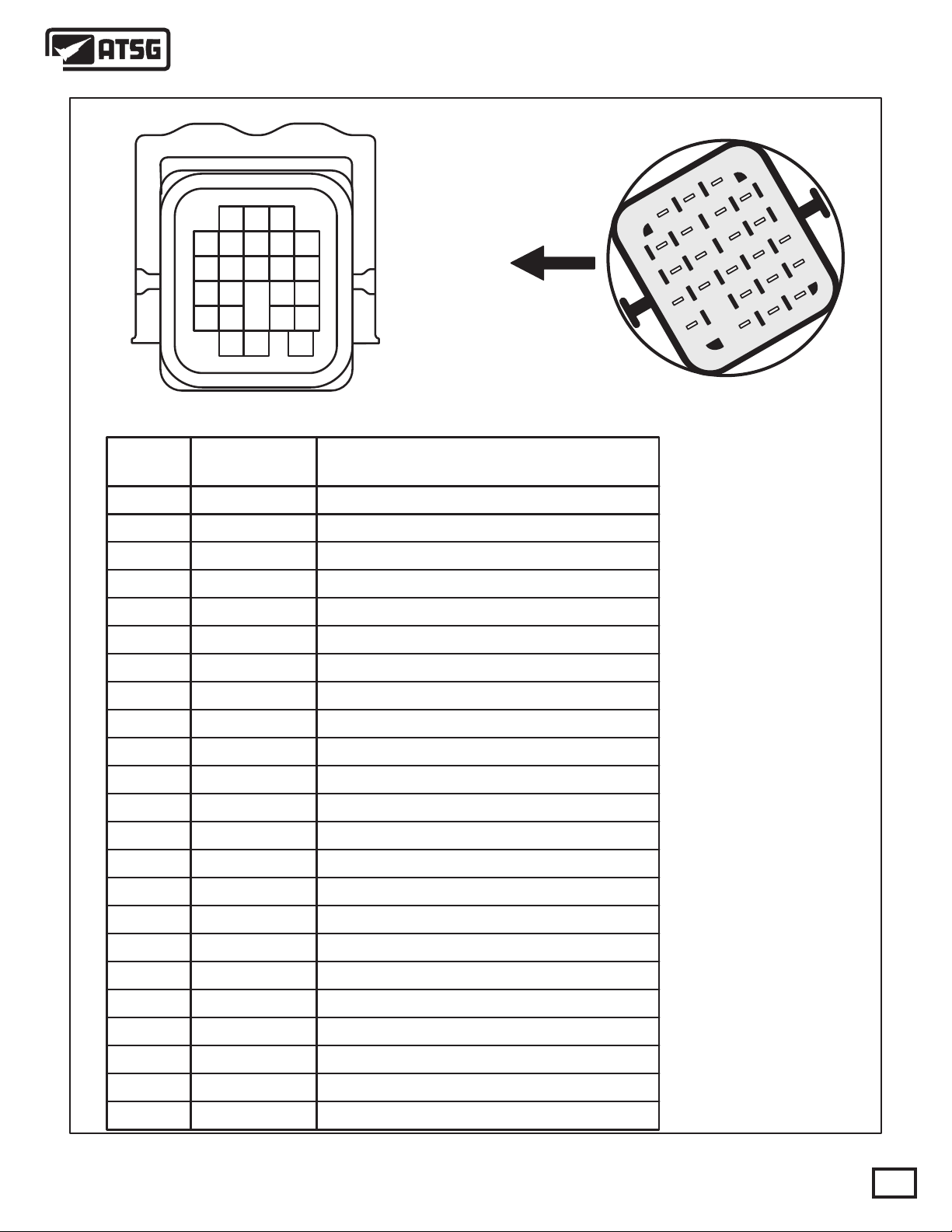
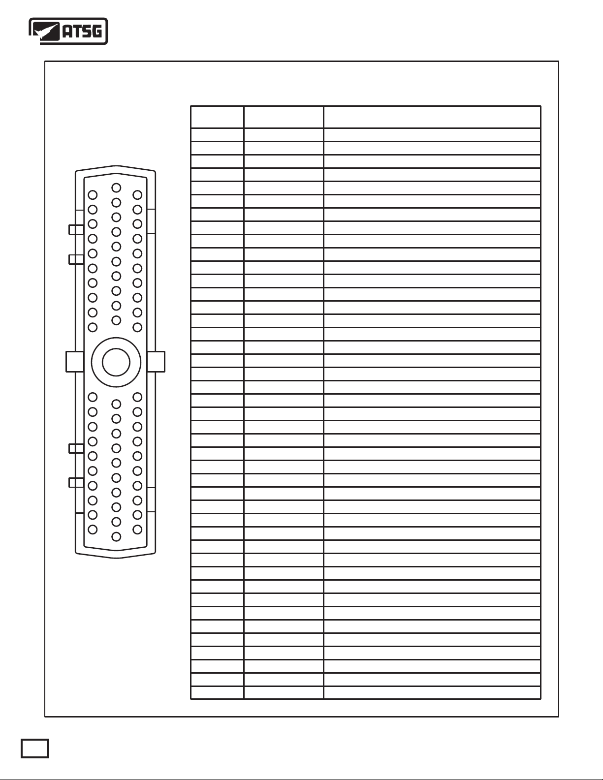
60-WAY CONNECTOR PIN CAVITY IDENTIFICATION AND FUNCTION
PIN
CAVITY
1
2
3
6
21
41
42
43
44
45
46
47
48
49
50
1
22
2
23
3
24
4
25
5
26
6
27
7
28
8
29
9
30
10
7
8
9
10
11
12
13
14
15
16
17
18
19
20
28
29
51
52
53
54
55
56
57
58
59
60
11
31
12
32
13
33
14
34
15
35
16
36
17
37
18
38
19
39
20
40
30
36
37
38
39
40
41
42
43
46
47
48
49
50
51
52
53
54
55
56
57
59
60
WIRE
COLOR
Lt. Green/Black
Tan/Black
Violet
Gray/Black
Pink
Red
Orange/Black
Yellow/Dk.Green
Orange/Dk. Blue
Brown
Dk. Blue/Black
Lt. Green/White
Pink/Yellow
Red
Red
Yellow/Dk. Blue
White/Dk. Blue
Lt. Green
White/Orange
Gray
Violet/Tan
Red
Black/Yellow
Gray/Lt. Blue
Black/Yellow
Violet/Lt. Green
White
Violet/White
Yellow/Violet
Lt. Green
Lt. Blue
Dk. Blue
Violet/White
Brown/Lt. Blue
Black/Lt. Blue
Red/Black
Black/Red
Violet
Pink
Red/White
Black/Yellow
Dk. Green/White
Brown
FUNCTION
Transmission Range Sensor T1 Signal
Back-up Lamp Relay Control
Transmission Range Sensor T3 Signal
Crankshaft Position Sensor Signal
SCI Transmit
Fused Ignition Switch Output (Start)
Overdrive Clutch Pressure Switch Signal
Torque Management Request
Fused Ignition Switch Output (Start-Run)
Overdrive Clutch Solenoid Control
Speed Sensor Ground
Output Speed Sensor Signal
Transmission Control Relay Control
Transmission Control Relay Output
Transmission Control Relay Output
Line Pressure Control Solenoid Control
2nd Clutch Solenoid Control
L/R-TCC Clutch Solenoid Control
Vehicle Speed Sensor Signal
Underdrive Clutch Pressure Switch Signal
Line Pressure Sensor Signal
Transmission Control Relay Output
Ground
5 Volt Supply
Ground
Multi-Select Solenoid Control
Transmission Range Sensor (T41) Signal
Transmission Range Sensor (T42) Signal
PCI Bus
SCI Recieve
2nd Clutch Pressure Switch Signal
4th Clutch Pressure Switch Signal
Overdrive Off Switch Signal
Low/Reverse Clutch Pressure Switch Signal
Sensor Ground
Input Speed Sensor Signal
Ground
Transmission Oil Temperature Sensor Signal
Underdrive Clutch Solenoid Control
Fused Battery Voltage
Ground
4th Clutch Solenoid Control
Overdrive Clutch Solenoid Control
12
NGC Information is located on Page 115
Figure 8
AUTOMATIC TRANSMISSION SERVICE GROUP
Copyright © 2009 ATSG
Page 13
Technical Service Information
POWER DISTRIBUTION CENTER
FUSE 5
30A
40 55 60 19 59 205318 3929 3748 5747 50 3 2 1 41 42 549
TRANSMISSION
CONTROL RELAY
16 15 53 38 301736
10 1217 721 23 2220 19 18 16 15 14 138 9 4 3 5 1 6112
NGC Schematic
located on Page 113
Pressure Sensor
Line
Pressure
Ground
5 Volt
Supply
Sensor
Signal
TRANSMISSION CONTROL MODULE
Input
Speed
Sensor
52 13 14
Output
Speed
Sensor
Copyright © 2009 ATSG
Back-up
Lamps
Starter
Relay
Ignition
Switch
12V
Back-Up
Lamp
Switch
Solenoid
Multi-Select
L/R
Pressure
Switch
Solenoid
Underdrive
2nd Clut
Pressure
Switch
TRS
T42
Signal
Solenoid
Overdrive
Pressure
Switch
OD
TRS
T41
Signal
Solenoid
2nd Clutch
4th Clut
Pressure
Switch
TRS
T1
Signal
Solenoid
4th Clutch
LR/TCC
UD
Pressure
Switch
TRS
T2
Signal
Solenoid
Control
Pressure
Solenoid
TRS
T3
Signal
TFT
Sensor
Figure 9
AUTOMATIC TRANSMISSION SERVICE GROUP
13
Page 14
Technical Service Information
TRANSMISSION CONTROL RELAY AND FUSE LOCATIONS EARLY MODELS
POWER DISTRIBUTION CENTER
AC
Clutch
Relay
Wiper
On/Off
Relay
Fuel
Pump
Relay
Spare
Relay
Horn
Relay
Wiper
Hi/Lo
Relay
Starter
Relay
Spare
Relay
Automatic
Shutdown
Relay
Heater
Relay
Down-
Stream
Transmission
Control
Relay
Heater
Relay
Up-
Stream
14
Fuse 5
(30A)
Copyright © 2009 ATSG
Figure 10
AUTOMATIC TRANSMISSION SERVICE GROUP
Page 15
Technical Service Information
INPUT SPEED
SENSOR
TITTJ243810187
P52119099AA 45RF
243810187P52119099AA
TO COOLER
099
AA
OUTPUT SPEED
SENSOR
LINE PRESSURE
SENSOR
LOCK-UP "ON"
FROM COOLER
PRESSURE
Figure 11
AUTOMATIC TRANSMISSION SERVICE GROUP
LOCK-UP "OFF"
PRESSURE
Copyright © 2009 ATSG
15
Page 16
Technical Service Information
MANDATORY TOOLS NEEDED FOR CHECKING PRESSURES ON 45RFE
l
l
l
l
l
l
l
l
l
l
l
l
l
l
l
l
l
l
l
l
l
l
l
l
l
l
l
l
l
l
l
l
l
l
l
l
l
l
l
l
l
l
l
l
l
l
l
l
l
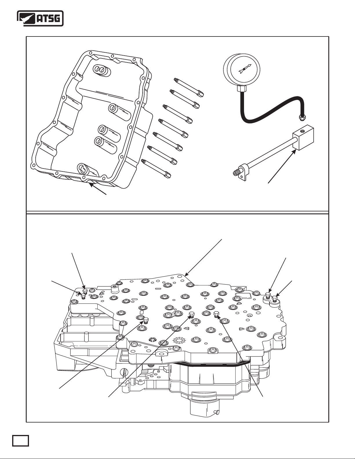
Pressure Tap Adapter Tool No. 8258, to check oil
pressures through the valve body taps.
Line Pressure
Low/Reverse
Clutch Pressure
Line Pressure Adapter Tool No. 8259, to install into
the line pressure sensor circuit, and then reinstall
the sensor and pressure gage.
VALVE BODY
Underdrive Clutch
Pressure
Reverse Clutch
Pressure
05111
1
AK
4799655
98
16
Overdrive Clutch
Pressure
4th Clutch
Pressure
Figure 12
AUTOMATIC TRANSMISSION SERVICE GROUP
2nd Clutch
Pressure
Copyright © 2009 ATSG
Page 17
Technical Service Information
COOLER FILTER
BYPASS VALVE
AA
099
243810187P52119099AA
P52119099AA 45RF
TITTJ243810187
COOLER FILTER
Low/Reverse
Clutch
2nd Clutch
AIR PRESSURE TESTS
4th Clutch
Overdrive
Clutch
Underdrive
Clutch
Reverse
Clutch
Figure 13
AUTOMATIC TRANSMISSION SERVICE GROUP
Copyright © 2009 ATSG
17
Page 18
T41
T42
T3
T1
T2
Technical Service Information
TRS/SOLENOID BODY TESTS
3000 5%
3000 5%
3000 5%
3000 5%
TRANSMISSION RANGE SENSOR CHART
CIRCUIT METER P R N OD 2 1
T42-C2
T3-C3
T1-C4
T2-C5
T41 & GRD OR CONNECTOR PIN 4 & GRD
T42 & GRD OR CONNECTOR PIN 5 & GRD
T3 & GRD OR CONNECTOR PIN 8 & GRD
T1 & GRD OR CONNECTOR PIN 9 & GRD
T2 & GRD OR CONNECTOR PIN 13 & GRD
C
C
O O
O O
C
CO O
C C
O
CCC
O O
O O O
O OT41-C1
OOO
C
C C
C = Closed O = Open
C
18
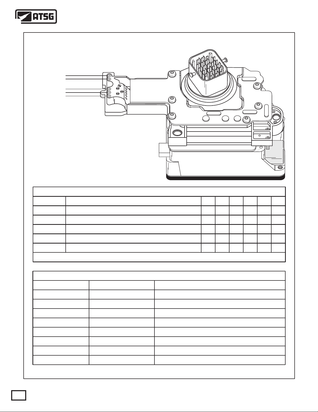
CONNECTOR PINS
LR/TCC 10 AND 2
OVERDRIVE
UNDERDRIVE
2ND CLUTCH
4TH CLUTCH
MULTI-SELECT
LINE PRESSURE
TOT SENSOR
AUTOMATIC TRANSMISSION SERVICE GROUP
SOLENOID RESISTANCE CHART
10 AND 7
10 AND 17
10 AND 20
10 AND 19
10 AND 21
10 AND 12
22 AND 23
Figure 14
RESISTANCESOLENOID
1.9 W @ 72°F
1.9 W @ 72°F
1.9 W @ 72°F
1.9 W @ 72°F
1.9 W @ 72°F
1.9 W @ 72°F
4.3 W @ 72°F
9.37k W @ 72°F
Copyright © 2009 ATSG
Page 19
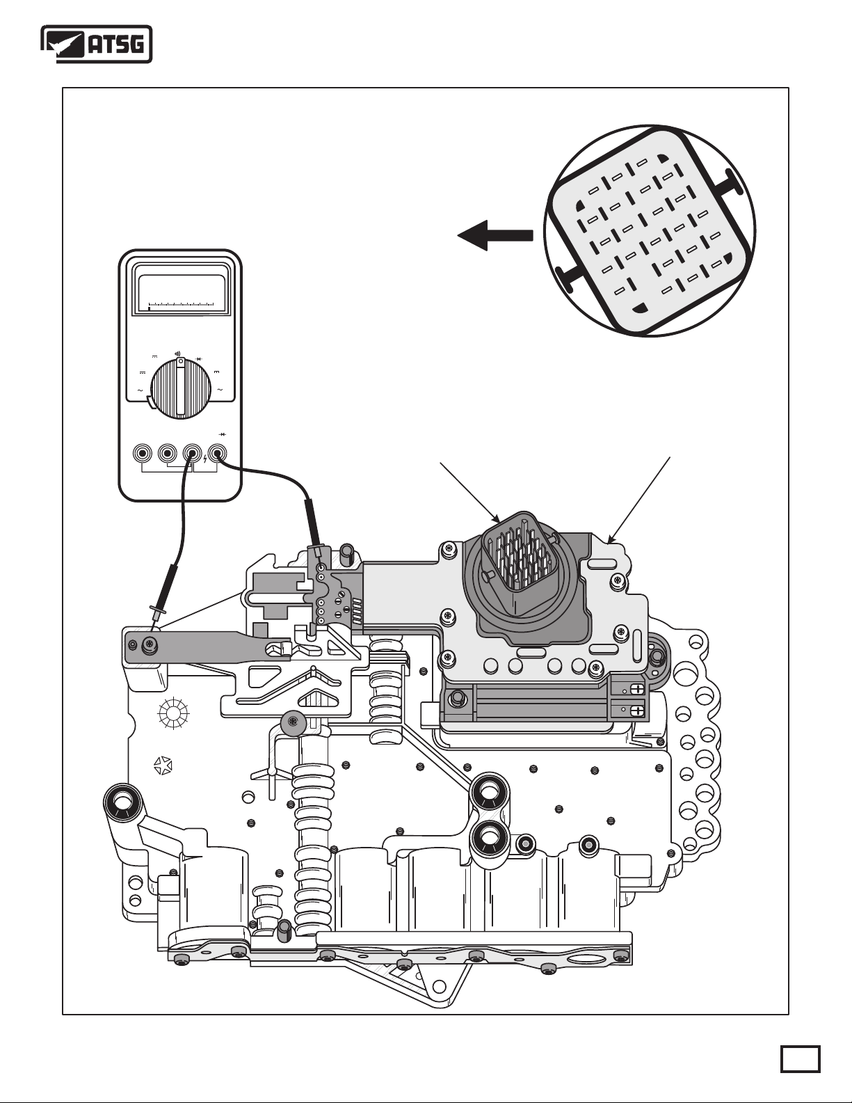
Technical Service Information
Meter shown checking T41 Circuit
and should correspond with chart
in Figure 14. Solenoid tests must
be made thru case connector pins.
W
0.1
"Front"
2122
17
23
20
16
12
81
19
15
7
13
14
1011
8
9
4
5
6
3
1
2
W
mV
V
RPM
V
OFF
mA
A
mA
A
V
W
RPMCOMmAA
23-WAY
CONNECTOR
97
TRANSMISSION RANGE SENSOR
AND SOLENOID BODY ASSEMBLY
Transmission
Case Connector
4799591
Figure 15
AUTOMATIC TRANSMISSION SERVICE GROUP
Copyright © 2009 ATSG
19
Page 20
OBDII
Codes
45RFE OBDII DIAGNOSTIC TROUBLE CODE LIST
Description
Technical Service Information
Limp-in MIL Illumination
P0120
P0600
P0705
P0715
P0720
P0725
P0731
P0732
P0733
P0734
P0736
P0740
P0750
Throttle Position Signal Out Of Range (29)
Bus Communication (19)
Internal TCM (17)P0604
Internal TCM (16)P0605
Malfunction Indicator Lamp Request P0700
Check Shifter Signal (28)
Input Speed Sensor Error (56)
Output Speed Sensor Error (57)
Engine Speed Sensor Circuit Error (18)
Gear Ratio Error In 1st Gear (51)
Gear Ratio Error In 2nd Gear (52)
Gear Ratio Error In 3rd Gear (53)
Gear Ratio Error In 4th Gear (54)
Gear Ratio Error In 4th Prime GearP0735
Gear Ratio Error In Reverse (50)
Torque Converter Clutch Control Circuit (38)
Low/Reverse Solenoid Circuit Error (C1)
2002 & UP
NO
NO
YES YES
YES YES
NO
YES
YES
YES
YES
YES
YES
YES
YES YES
YES
NO
YES
NO
NO
YES
NO
YES
YES
YES
YES
YES
YES
YES
YES
YES
YES
P0755
P0760
P0765
P0770
P0841
P0870
P0871
P0875
P0876
P0884
P0888
P0890
2nd Clutch Solenoid Circuit Error (C2)
Overdrive Solenoid Circuit Error (C3)
Underdrive Solenoid Circuit Error (C5)
4th Clutch Solenoid Circuit Error (C4)
L/R pressure Switch sense Circuit
2nd Clutch hydraulic pressure test FailureP0845
2nd Clutch Pressure Switch Sense CircuitP0846
Line Pressure FaultP0867
Line Pressure LowP0868
Line Pressure HighP0869
OD Clutch hydraulic pressure test Failure
OD Clutch Pressure Switch Sense Circuit
UD Clutch hydraulic pressure test Failure
UD Clutch Pressure Switch Sense Circuit
Power up at speed
Trans Control Relay output Always Off
Switched Battery Voltage Failure
NOTE: Letters or digits in parenthesis are for use with DRB scan tool. 545RFE DTC's are located on Page 112
2002 & UP
2002 & UP
2002 & UP
2002 & UP
2002 & UP
2002 & UP
2002 & UP
2002 & UP
2002 & UP
2002 & UP
2002 & UP
2002 & UP
2002 & UP
Figure 16
YES
YES
YES
YES
YES YES
YES YES
YES YES
NO NO
NO NO
NO NO
YES YES
YES YES
YES YES
YES YES
NO NO
YES YES
YES YES
Copyright © 2009 ATSG
YES
YES
YES
YES
20
AUTOMATIC TRANSMISSION SERVICE GROUP
Page 21

Technical Service Information
45RFE OBDII DIAGNOSTIC TROUBLE CODE LIST
OBDII
Codes
P0891
P0932
P0944
P0987
P0988
P1720
P1721
P1722
P1724
P1726
P1727
P1728
P1732
P1733
P1734
P1735
P1736
P1737
P1738
P1739
P1765
P1767
P1768
P1770
P1771
P1772
P1773
P1775
P1776
P1781
P1784
P1787
P1790
P1792
P1793
P1794
P1799
P2700
P2701 Inadequate Element Volume 2nd Clutch
P2702 Inadequate Element Volume Overdrive Clutch
P2703 Inadequate Element Volume Underdrive Clutch
P2704 Inadequate Element Volume 4th Clutch
P2706 Multi-Select Solenoid Circuit Fault
Description
Transmission Control Relay always ON
Line Pressure Sensor Fault
Loss of Prime
4th Clutch Hydraulic Pressure Test Failure
4th Clutch Pressure Switch Sense Circuit
Battery was DisconnectedP1684
Bus communication with Engine Control Module faultP1694
Restricted Port in T3 (65)P1715
Line Pressure Out Of Range (C8)
Line Pressure Sensor Voltage Out Of Range (CA)
Line Pressure Low (C9)
Line Pressure High (CB)
Overdrive Pressure Switch Did Not Close (BO)
Underdrive Pressure Switch Did Not Close (A8)
2nd Clutch Pressure Switch Did Not Close (A2)
Overdrive Pressure Switch Circuit Error (90)
Underdrive Pressure Switch Circuit Error (88)
2nd Clutch Pressure Switch Circuit Error (82)
Inadequate Element Volume 4th Clutch (64)
Gear ratio in 2nd Prime (55)
Multi-Select Solenoid Circuit Error (C6)
High Temperature Operation Activated (Info Only) (75)
Power-Up At Speed (76)
Switched Battery Voltage Failure (80)
Transmission Control Relay Always ON (14)
Transmission Control Relay Always OFF (15)
Inadequate Element Volume L/R (60)
Inadequate Element Volume 2nd Clutch (61)
Inadequate Element Volume OD Clutch (62)
Inadequate Element Volume UD Clutch (63)
Solenoid Switch Valve Stuck In TCC Position (37)
Solenoid Switch Valve Stuck In L/R Position (47)
OD Pressure Switch Circuit Error (84)
Low/Reverse Pressure Switch Circuit Error (81)
OD Hydraulic pressure switch Failure (A4)
Fault Immediately After Shift (36)
Battery Was Disconnected (12)
Torque Management Request (TRD) Sense Circuit (48)
Speed Sensor Ground Error (58)
Calculated Oil Temperature In Use (74)
Inadequate Element Volume Low Reverse Clutch
2002 & UP
NOTE: Letters or digits in parenthesis are for use with DRB scan tool
2002 & UP
2002 & UP
2002 & UP
2002 & UP
2002 & UP
2002 & UP
2002 & UP
AUTOMATIC TRANSMISSION SERVICE GROUP
2002 & UP
2002 & UP
2002 & UP
2002 & UP
Figure 17
2002 & UP
Limp-in MIL Illumination
YES
YES
YES
YES
YES
NO
NO
NO
NO
NO
NO
NO
YES YES
YES
YES
YES
YES YES
YES YES
NO
YES YES
YES YES
NO
NO
YES YES
YES
YES
YES YES
NO
NO
NO
NO
YES
YES
YES
YES
YES
NO
NO
YES
NO
NO NO
NO NO
NO NO
NO NO
NO NO
YES YES
Copyright © 2009 ATSG
YES
YES
YES
YES
YES
NO
NO
NO
NO
NO
NO
NO
YES
YES
YES
NO
NO
NO
YES
YES
NO
NO
NO
YES
YES
YES
YES
YES
YES
NO
NO
YES
NO
21
Page 22
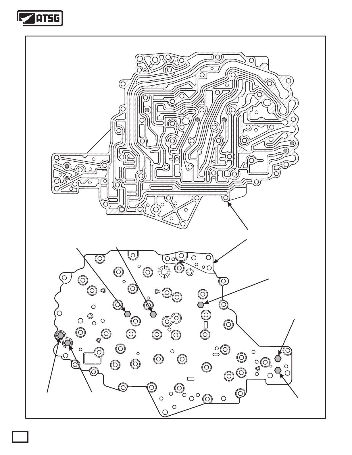
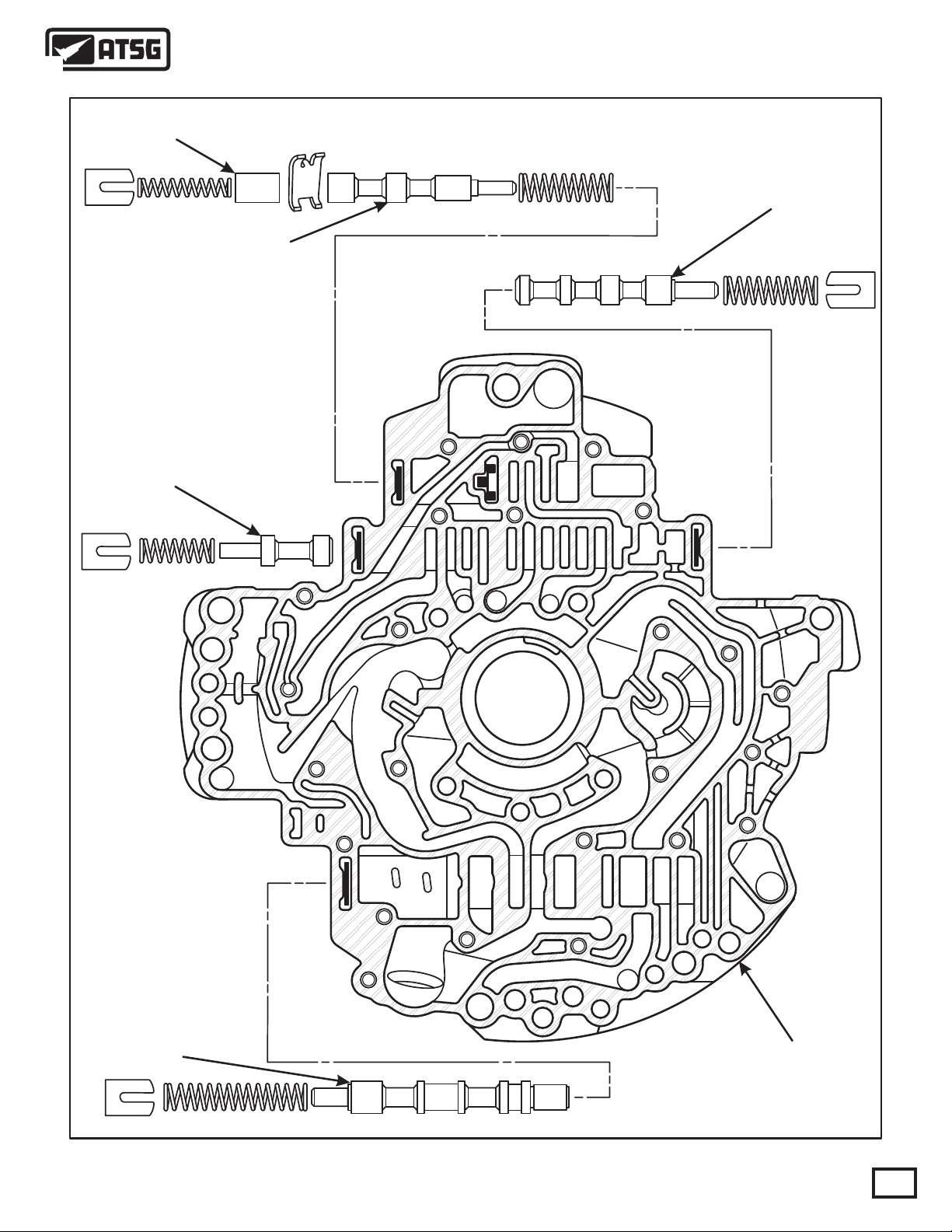
Technical Service Information
45/545RFE TRANSFER PLATE
Reverse Clutch
Pressure
2nd Clutch
Pressure
Underdrive Clutch
Pressure
4th Clutch
Pressure
98
4799655
05111
TRANSFER PLATE
AK
1
Overdrive Clutch
Pressure
Low/Reverse Clutch
Pressure
Line Pressure
22
Copyright © 2009 ATSG
Figure 18
AUTOMATIC TRANSMISSION SERVICE GROUP
Page 23
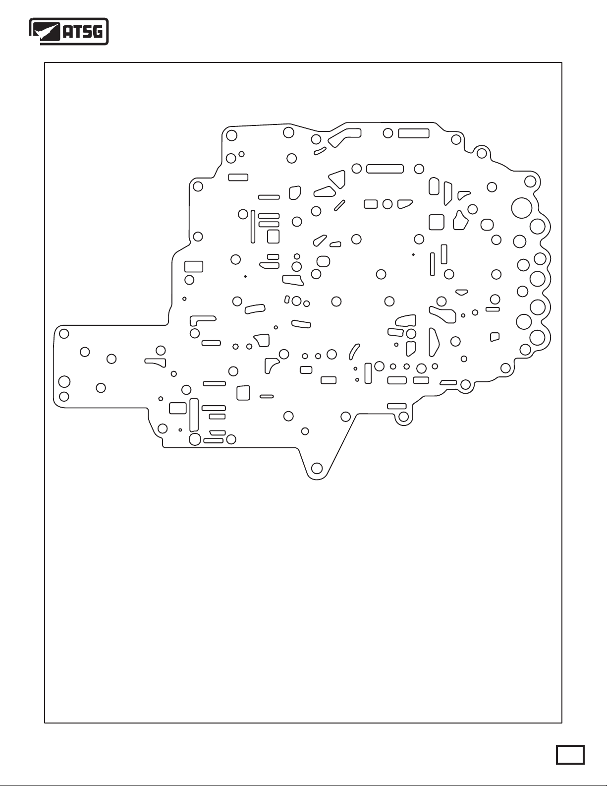
Technical Service Information
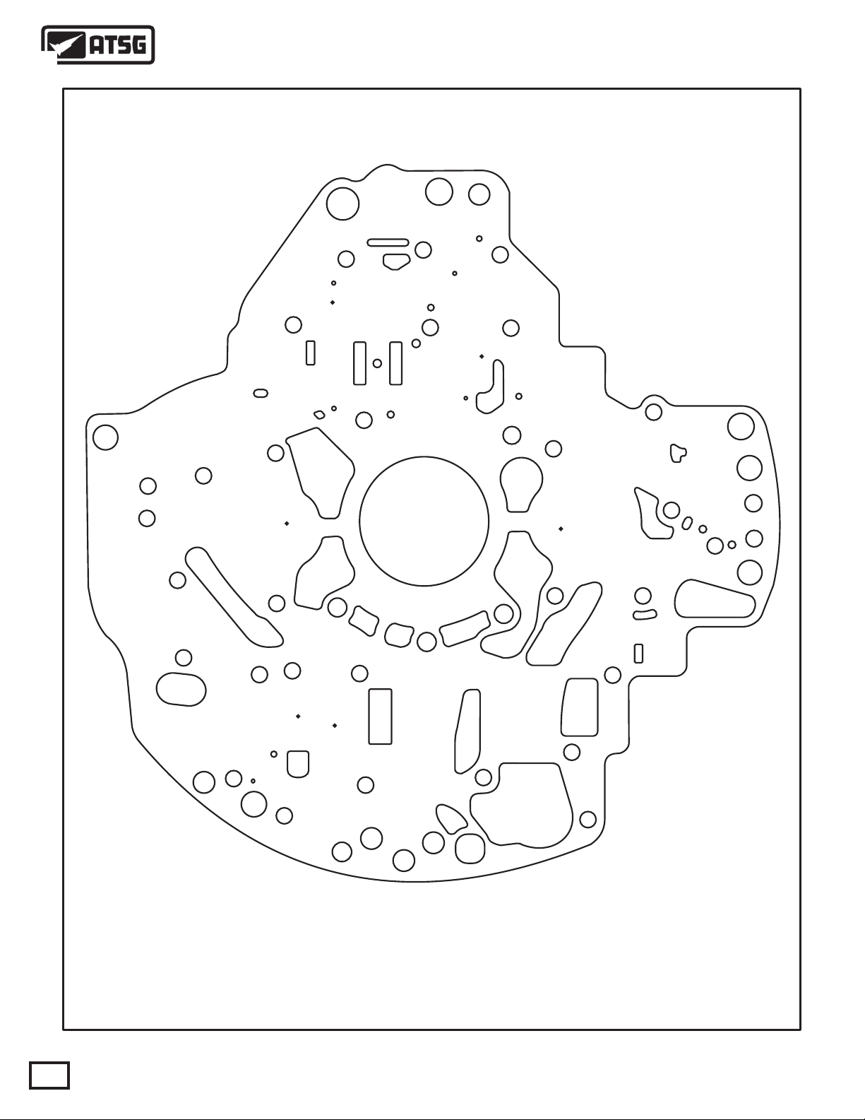
45/545RFE VALVE BODY SPACER PLATE
Figure 19
AUTOMATIC TRANSMISSION SERVICE GROUP
Copyright © 2009 ATSG
23
Page 24
Technical Service Information
45/545RFE ACCUMULATOR AND CHECKBALL LOCATIONS
SEVEN CHECKBALL LOCATIONS
ARE SHOWN BELOW
OD
ACCUM
UD
ACCUM
4TH CLUT
ACCUM
2ND CLUT
ACCUM
Figure 19
LOW/REV
ACCUM
Copyright © 2009 ATSG
24
AUTOMATIC TRANSMISSION SERVICE GROUP
Page 25
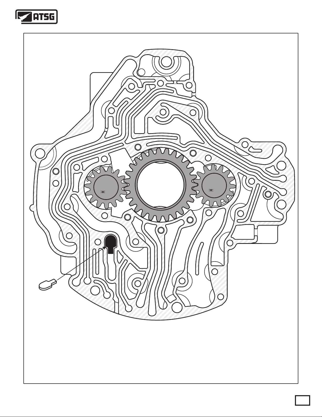
Technical Service Information
45/545RFE OIL PUMP BODY AND GEARS
2
Shuttle Valve
A dual stage oil pump is also new for the 45RFE. The pump has three gears, one drive gear and two
driven gears as shown above. Both stages of the pump supply fluid during idle and at low engine
speeds. Under these conditions there is not enough pressure from the primary stage to close the
shuttle valve. As engine speed increases, so does the output from the primary stage. Once the
pressure from the primary stage builds up, the shuttle valve is forced closed and in this condition the
secondary stage has no effect and the primary side supplies all of the pressure needed for proper
transmission operation. Note: early casting shown.
3
Copyright © 2009 ATSG
Figure 20
AUTOMATIC TRANSMISSION SERVICE GROUP
25
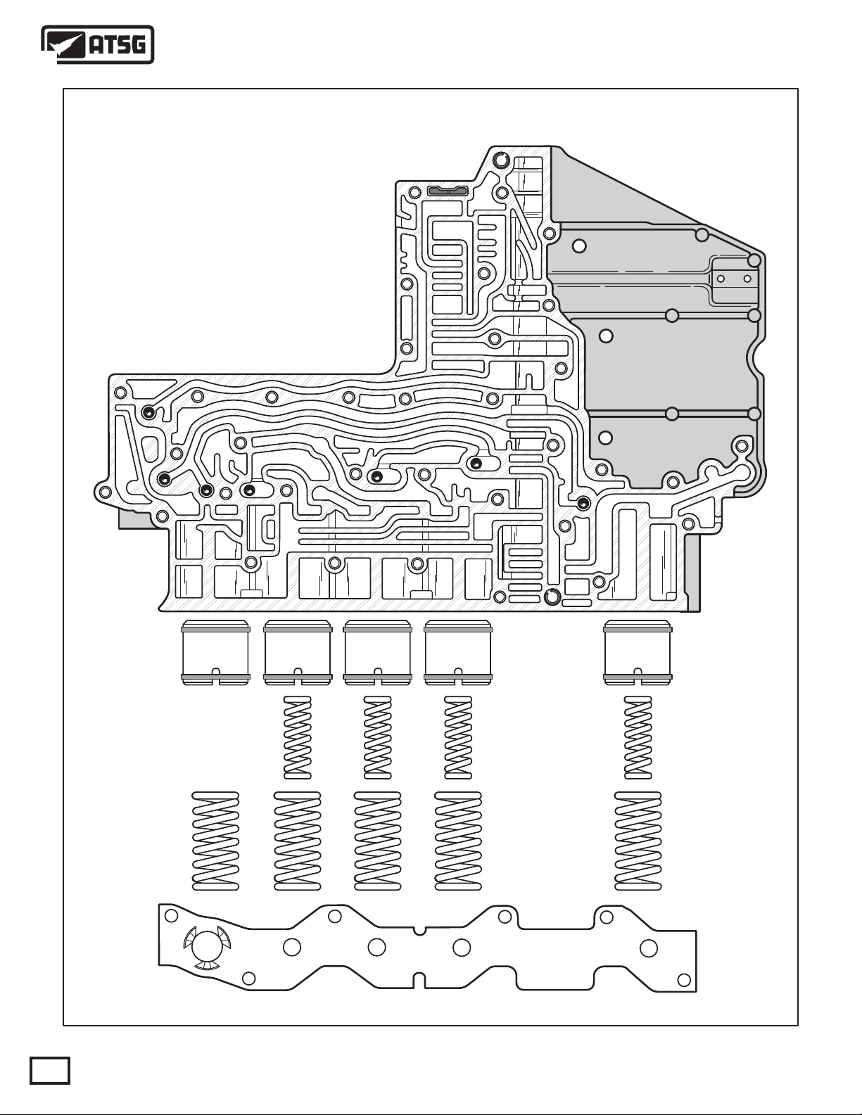
Page 26
Technical Service Information
45/545RFE PUMP SPACER PLATE
26
Early plate shown
Copyright © 2009 ATSG
Figure 21
AUTOMATIC TRANSMISSION SERVICE GROUP
Page 27
Technical Service Information
Torque Converter Clutch
Accumulator Valve
Torque Converter Clutch
Control Valve
Torque Converter Clutch
Limit Valve
VALVE LINE-UP IDENTIFICATION AND
LOCATIONS IN PUMP COVER
Torque Converter Clutch
Switch Valve
Pressure Regulator Valve
Early pump shown
Figure 22
AUTOMATIC TRANSMISSION SERVICE GROUP
PUMP COVER
Copyright © 2009 ATSG
27
Page 28
Exhaust
Technical Service Information
45/545RFE OIL PUMP COVER PASSAGE
AND FEED HOLE IDENTIFICATION
Converter
Release
Lube
Reverse
Clutch
Underdrive
Clutch
Overdrive
Clutch
4799578
Early pump shown
28
Copyright © 2009 ATSG
Figure 23
AUTOMATIC TRANSMISSION SERVICE GROUP
Page 29
Technical Service Information
45/545RFE OIL PUMP STATOR PASSAGE
AND FEED HOLE IDENTIFICATION
Overdrive
Clutch
Underdrive
Clutch
Reverse Clutch
Bleed Orifice
Overdrive Clutch
Bleed Orifice
Lube
Converter
Release
Reverse
Clutch
Exhaust
Exhaust
Overdrive
Clutch
Underdrive
Clutch
Figure 24
AUTOMATIC TRANSMISSION SERVICE GROUP
Reverse
Clutch
Copyright © 2009 ATSG
29
Page 30
Technical Service Information
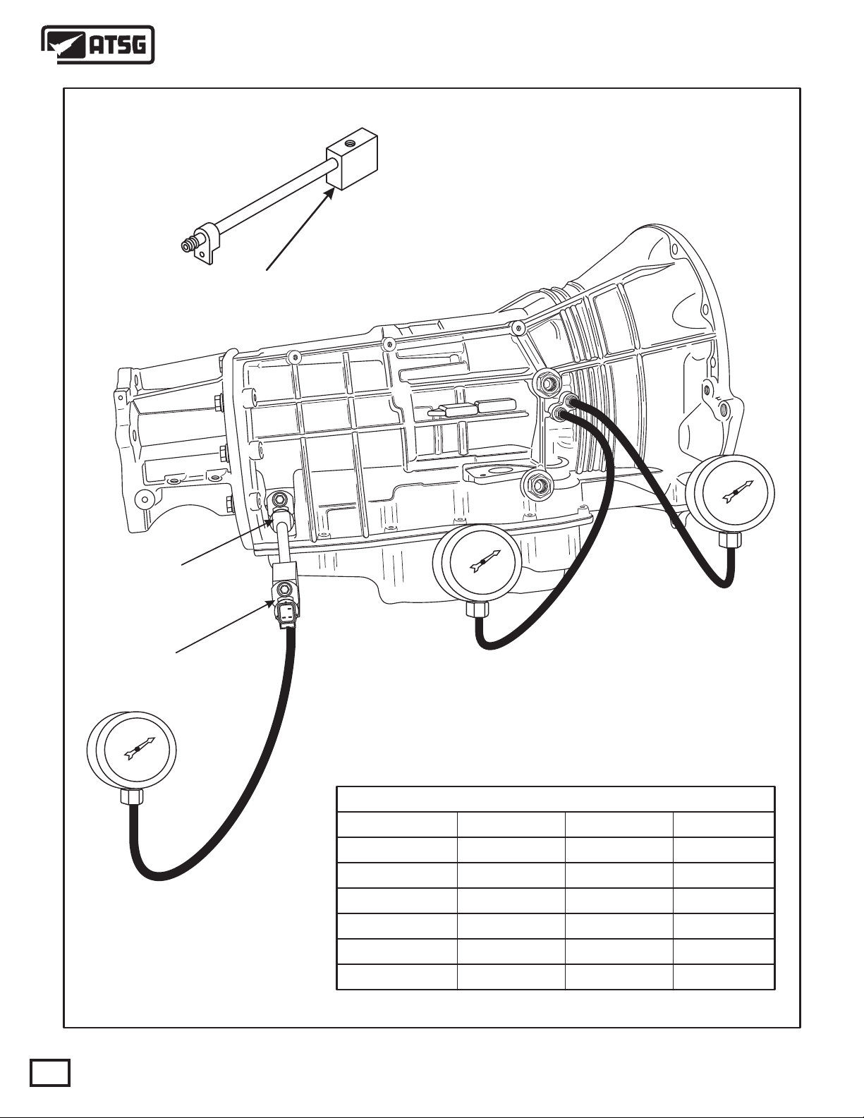
OIL PRESSURE TESTS
Line Pressure Adapter Tool No. 8259, to install into
the line pressure sensor circuit, and then reinstall
the sensor and pressure gage.
Tool No.8259
Line Pressure
Sensor
l
l
l
l
l
l
l
l
l
l
l
l
l
l
l
l
l
l
l
l
l
l
l
l
l
l
l
l
l
l
l
l
l
l
l
l
l
l
l
l
l
l
l
l
l
l
l
l
l
l
l
l
l
l
l
l
l
l
l
l
l
l
l
l
l
l
l
l
l
l
l
l
l
l
l
l
l
l
l
l
l
l
l
l
l
l
l
l
l
l
l
l
l
l
l
l
l
l
l
l
l
l
l
l
l
l
l
l
l
l
l
l
l
l
l
l
l
l
l
l
l
l
l
l
l
l
l
l
l
l
l
l
l
l
l
l
l
l
l
l
LOCK-UP "OFF"
PRESSURE
LOCK-UP "ON"
PRESSURE
l
l
l
l
l
l
l
PRESSURE CHART
GEAR
PARK
LINE
35-165 35-118
TCC ON TCC OFF
15-80
30
MAIN LINE
PRESSURE
REVERSE
NEUTRAL
OD-1ST
TCC OFF
TCC ON
45-250
35-165
35-165
35-165
35-165
Figure 25
AUTOMATIC TRANSMISSION SERVICE GROUP
15-80
15-80
15-80
35-80
Copyright © 2009 ATSG
40-11840-75
35-118
35-118
35-118
0
Page 31

Technical Service Information
(1) Transmission fluid level must be checked before
performing the pressure tests and must be at normal
operating temperature for accurate check. Drive
vehicle if necessary to bring fluid temperature up to
normal operating temperature of 82°C (180°F).
(2) Position vehicle on flat level surface.
(3) Start and run engine at curb idle speed.
(4) Apply Parking Brakes.
(5) Shift transmission through all gear ranges and
then back to the Neutral position.
(6) Remove dipstick and check fluid level.
(A) Correct level is in crosshatch area.
(B) Correct maximum level is to MAX arrow.
(C) Incorrect level is at or below MIN line.
(7) If fluid level is low, add only enough of the
Mopar® ATF Plus 3 or 4, Type 7176 to restore correct
fluid level. Do not overfill (See Figure 26).
Dexron II fluid is NOT recommended. Clutch
chatter can result from the use of improper fluid.
PRESSURE TEST LOCATIONS AND PROCEDURE
There are only two pressure taps supplied on the
transmission case. The torque converter ON and
torque converter OFF taps are located on the right side
of the transmission case, shown in Figure 25.
There are two available methods to determine main
line pressure. The DRB Scan Tool can be used to read
main line pressure from the line pressure sensor. The
2nd method is to install Line Pressure Adapter 8259
into the transmission case, and re-install the line
pressure sensor and the pressure gauge into the
adapter, shown in Figure 25. This will allow a
comparison of the DRB readings and the pressure
gauge to determine the accuracy of the feedback to the
controller. Refer to the chart in Figure 25 for proper
pressure readings.
To access any of the other pressure tap locations, the
transmission oil pan must be removed, the pressure
taps removed from the valve body and the Valve Body
Pressure Tap Adapter 8258 installed. Refer to Figure
12 on Page 16. The extensions supplied with Adapter
8258 will allow the installation of pressure gauges to
the valve body to test individual clutch pack
pressures. Refer to Figure 12 on Page 16 for pressure
tap identification.
GENERAL OPERATION INFORMATIONFLUID LEVEL CHECK PROCEDURE
The 45/545RFE transmission is a sophisticated,
multi-range, electronically controlled transmission
which combines optimized gear ratios for very
responsive performance and state of the art efficiency.
Features include driver adaptive shifting and three
planetary gear sets to provide wide ratio capability
with precise ratio steps to optimize driveability. The
three planetary gear sets also make available a unique
alternate 2nd gear ratio. The primary 2nd gear ratio
falls between 1st and 3rd gears for normal upshifts on
acceleration. The alternate 2nd gear ratio (2nd Prime)
allows for a smoother 4-2 kickdown at high speeds to
provide 2nd gear passing performance over a wider
hi-way crusing range.
The 45/545RFE offers full electronic control of all
automatic up and downshifts, and features real-time
adaptive closed-loop shift and pressure control.
Electronic shift and converter clutch controls help
protect the transmission from damage due to high
temperatures, which can occur under severe operating
conditions.
The 45/545RFE also features a unique dual stage oil
pump with electronic output pressure control. Under
most driving conditions, pump output pressure
greatly exceeds that which is needed to keep the
clutches applied. The 45/545RFE pump pressure
control system monitors input torque and adjusts the
pump pressure accordingly. The primary stage of the
pump works continuously. The second stage is bypassed when demand is low. The control system also
monitors input and output speed and, if clutch
slippage is observed, the pressure control solenoid
duty cycle is varied, increasing pressure in proportion
to demand.
PRIMARY MECHANICAL COMPONENTS
3 MULTIPLE DISC INPUT CLUTCHES
3 MULTIPLE DISC HOLDING CLUTCHES
3 PLANETARY GEAR SETS
5 HYDRAULIC ACCUMULATORS
DUAL STAGE HYDRAULIC OIL PUMP
VALVE BODY
TRANSMISSION RANGE SENSOR/SOLENOID PACK
AUTOMATIC TRANSMISSION SERVICE GROUP
31
Page 32

OK MAXMIN
ACCEPTABLE
FLUID LEVEL
Technical Service Information
TYPICAL
DIPSTICK
MAXIMUM CORRECT
FLUID LEVEL
Figure 26
"O" RING
TRANSMISSION DISASSEMBLY
1. Drain fluid from the transmission.
2. Clean exterior of the transmission thoroughly
with a suitable solvent or pressure washer.
3. Remove the torque converter from the trans mission, remove and discard the "O" ring from
the converter hub (See Figure 27).
4. Remove the manual shift lever.
5. Remove both input and output speed sensors
from the case, as shown in Figure 28, remove
and discard both "O" rings.
6. Remove the line pressure sensor from the case,
as shown in Figure 29, remove and discard the
"O" rings.
7. Remove the 12 extension housing to case
retaining bolts using a 15mm socket and then
remove extension housing (See Figure 30).
8. Remove the park gear snap ring from output
shaft and remove park gear (See Figure 30).
9. Using a dial indicator, measure and record the
output shaft end-play reading.
10. Using a dial indicator, measure and record the
input shaft end-play reading.
TITTJ243810187
P52119099AA 45RF
243810187P52119099AA
NOTE: When measuring the input shaft end-play,
two "stops" will be felt. When the input shaft is
pushed inward and the indicator zeroed, the first
stop felt when the input shaft is pulled outward is the
movement of the input shaft in the input clutch hub.
This value should not be included in the end-play
measurement and therefore must be recorded and
subtracted from the total dial indicator reading.
Figure 27
099
AA
32
Copyright © 2009 ATSG
Figure 28 Figure 29
AUTOMATIC TRANSMISSION SERVICE GROUP
Page 33

TITTJ243810187
P52119099AA 45RF
243810187P52119099AA
Technical Service Information
PARK GEAR
099
AA
PARK GEAR
SNAP RING
Figure 30
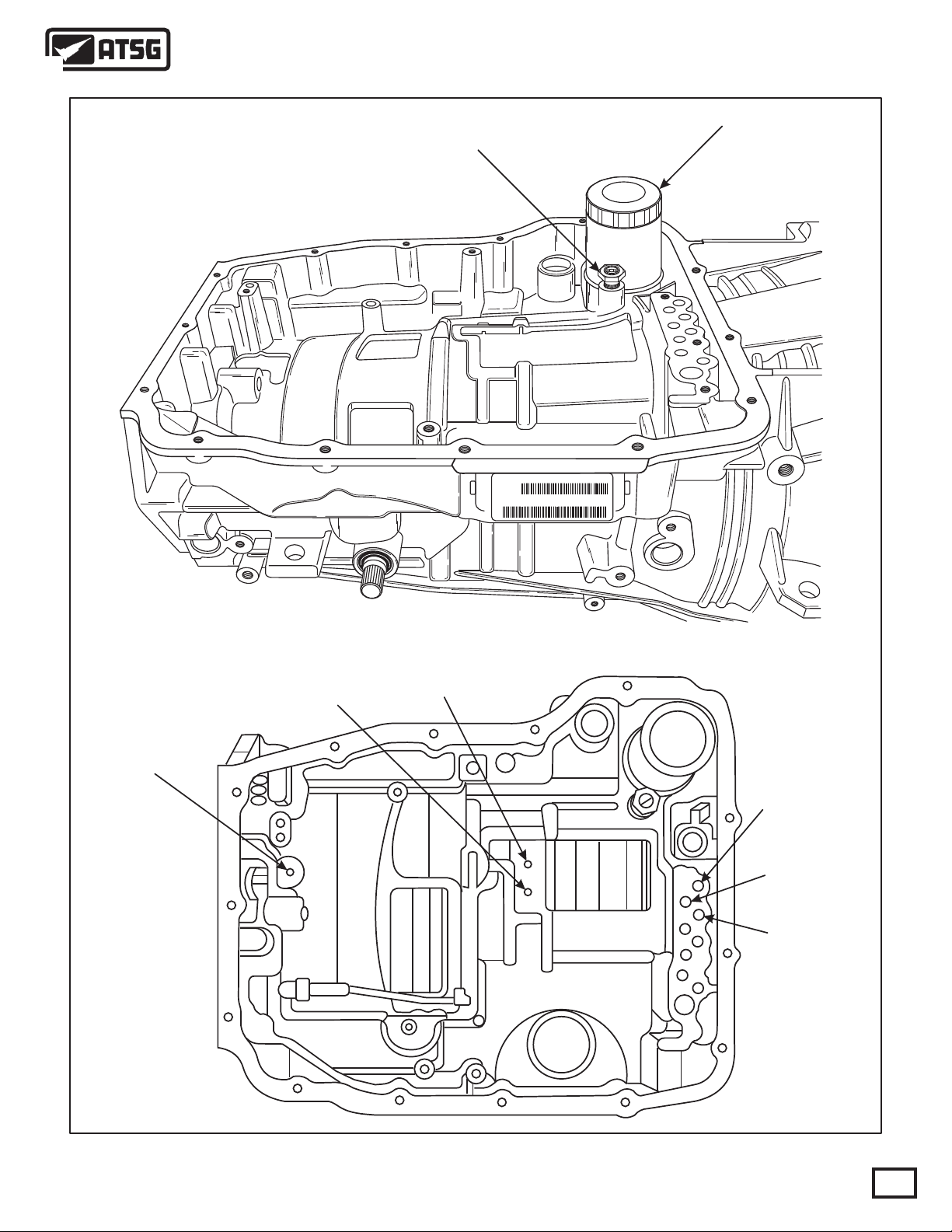
10. Remove the 15 bottom pan bolts, using an 8mm
socket, as shown in Figure 31.
11. Remove bottom oil pan as shown in Figure 31.
NOTE: This unit uses no gaskets anywhere. The
extension housing and bottom pan are sealed with
RTV.
12. Remove the bottom pan filter retaining screw,
using a 25 Torx bit (See Figure 32).
13. Remove and discard the bottom pan oil filter,
as shown in Figure 32.
Continued on next Page.
05111
4799655
1
AK
98
05111
4799655
1
AK
98
AA
099
243810187P52119099AA
P52119099AA 45RF
TITTJ243810187
Figure 31 Figure 32
AUTOMATIC TRANSMISSION SERVICE GROUP
AA
099
243810187P52119099AA
P52119099AA 45RF
TITTJ243810187
Copyright © 2009 ATSG
33
Page 34

VALVE BODY
RETAINING BOLTS
Technical Service Information
05111
4799655
1
AK
98
VALVE BODY
RETAINING BOLTS
VALVE BODY
RETAINING BOLTS
Figure 33
COOLER FILTER
BYPASS VALVE
05111
4799655
1
AK
98
COOLER FILTER
34
AA
099
243810187P52119099AA
P52119099AA 45RF
TITTJ243810187
Copyright © 2009 ATSG
Figure 34 Figure 35
AUTOMATIC TRANSMISSION SERVICE GROUP
AA
099
243810187P52119099AA
P52119099AA 45RF
TITTJ243810187
Page 35

Technical Service Information
14. Remove the six valve body retaining bolts that
are illustrated in Figure 33, using 8mm socket.
15. Remove the complete valve body and the
TRS/Solenoid body as an assembly as shown
in Figure 34, and set aside for component
disassembly.
16. Remove and discard the cooler oil filter from
the transmission case as shown in Figure 35.
17. Remove the cooler by-pass valve from case,
as shown in Figure 35.
18. Remove the outer snap ring retaining the trans mission front cover in the transmission case as
shown in Figure 36.
19. Remove the inner snap ring retaining the front
cover to the oil pump as shown in Figure 36.
20. Reach through one of the case openings in the
valve body area with a long blunted tool, and
tap the transmission front cover from the case.
Refer to Figure 36.
21. Remove the six bolts retaining the oil pump in
the transmission case (See Figure 36).
22. Remove the oil pump from the transmission.
Hold down on the input shaft to prevent the
input clutch housing assembly from coming
out with the oil pump (See Figure 36.
23. Set the oil pump assembly aside for component
disassembly. Note: Early pump illustrated.
The 07 and up pump does not house the front
seal and does not require the #5 snap ring.
5
4
3
2
4
6
1
7
9
1
9
2
3
3
8
5
C
R
-
2
A
2
1
0
2
Continued on next Page.
2
1
1. COMPLETE PUMP ASSEMBLY.
2. PUMP TO CASE RETAINING BOLTS (6 REQUIRED).
3. PUMP COVER PLATE (MOLDED SEALS).
4. PUMP COVER PLATE OUTER RETAINING SNAP RING.
5. PUMP COVER PLATE INNER RETAINING SNAP RING.
Copyright © 2009 ATSG
Figure 36
AUTOMATIC TRANSMISSION SERVICE GROUP
35
Page 36

Technical Service Information
NUMBER ONE
THRUST BEARING
INPUT CLUTCH
HOUSING ASSEMBLY
24. Remove the input clutch housing assembly by
lifting straight up as shown in Figure 37.
25. Remove the number one thrust bearing from
inside the input housing as shown in Figure 37.
26. Remove the number 5 selective thrust bearing
from back side of the input housing, or from
the 2-4 support in transmission (See Figure 37).
27. Set the input clutch housing assembly aside for
component disassembly.
28. Remove the 2-4 clutch retainer front snap ring,
which is a tapered snap ring, from transmission
case as shown in Figure 38.
29. Remove the 2-4 clutch retainer from the trans mission case, as shown in Figure 38, and set
aside for component disassembly.
30. Remove the 2-4 clutch retainer rear snap ring,
which is a flat snap ring, from the transmission
case as shown in Figure 38.
31. Remove the 2nd clutch pack, 2 steel plates and
2 friction plates, from the transmission case as
shown in Figure 39.
32. Remove the 2nd clutch pressure plate from the
transmission case as shown in Figure 39.
NUMBER FIVE
THRUST BEARING
(SELECTIVE)
Continued on Page 38.
36
Copyright © 2009 ATSG
Figure 37
AUTOMATIC TRANSMISSION SERVICE GROUP
Page 37

Technical Service Information
1
1
2
3
3
4
4
2
5
1. 2-4 CLUTCH RETAINER TAPERED SNAP RING (GOES IN CASE).
2. NUMBER 5 THRUST BEARING (SELECTIVE).
3. 2-4 CLUTCH RETAINER.
4. 2-4 CLUTCH RETAINER FLAT SNAP RING (GOES IN CASE).
Figure 38
AUTOMATIC TRANSMISSION SERVICE GROUP
5
1. SECOND CLUTCH STEEL PLATES (2 REQUIRED).
2. SECOND CLUTCH FRICTION PLATES (2 REQUIRED).
3. SECOND CLUTCH BACKING PLATE.
4. NUMBER SIX THRUST BEARING.
Copyright © 2009 ATSG
Figure 39
37
Page 38

Technical Service Information
33. Remove the number 6 thrust bearing if it is
present. It may have been stuck to the 2-4
1
2
3
4
retainer (See Figure 40).
34. Remove the rear selective plate as shown in
Figure 40.
35. Remove reaction internal ring gear assembly
as shown in Figure 40.
36. Remove the number 7 thrust bearing as shown
in Figure 40.
37. Remove the reaction sun gear as shown in
Figure 40.
38. Remove the number 8 thrust bearing as shown
in Figure 40.
39. Remove the reaction carrier/reverse sun gear
assembly as shown in Figure 41.
40. Remove the number 9 thrust bearing as shown
in Figure 41.
5
1
6
2
1. NUMBER 6 THRUST BEARING.
2. REAR SELECTIVE THRUST PLATE.
3. REACTION INTERNAL RING GEAR ASSEMBLY.
4. NUMBER 7 THRUST BEARING.
5. REACTION SUN GEAR.
6. NUMBER 8 THRUST BEARING.
Figure 40 Figure 41
38
1. REACTION CARRIER/REVERSE SUN GEAR ASSEMBLY.
2. NUMBER 9 THRUST BEARING.
Copyright © 2009 ATSG Copyright © 2009 ATSG
AUTOMATIC TRANSMISSION SERVICE GROUP
Page 39

Technical Service Information
41. Remove reverse carrier/input ring gear "flat"
snap ring from the input internal ring gear as
shown in Figure 42.
42. Remove the reverse carrier/input ring gear
assembly as shown in Figure 42.
43. Remove the number 10 thrust bearing assembly
as shown in Figure 42.
44. Remove the input sun gear assembly as shown
in Figure 43.
45. Remove the number 11 thrust bearing as shown
in Figure 43.
46. Remove the input planetary carrier/reverse
internal ring gear as shown in Figure 43.
Continued on Page 40.
1
1
2
3
2
3
1. REVERSE CARRIER/INPUT RING GEAR "FLAT" SNAP RING.
2. REVERSE PLANETARY CARRIER ASSEMBLY.
3. NUMBER 10 THRUST BEARING.
Figure 42
AUTOMATIC TRANSMISSION SERVICE GROUP
1. INPUT SUN GEAR ASSEMBLY.
2. INPUT CARRIER/REVERSE INTERNAL RING GEAR ASSEMBLY.
3. NUMBER 11 THRUST BEARING.
Copyright © 2009 ATSG
Figure 43
39
Page 40

Technical Service Information
47. Remove the input internal ring gear assembly
from the transmission case (See Figure 44).
48. Remove the number 12 thrust bearing from the
low/reverse clutch housing assembly as shown
in Figure 44.
49. Remove the "Tapered" snap ring from the case
that retains the low/reverse clutch housing in
transmission case (See Figure 45).
50. Remove low/reverse clutch housing assembly
from the transmission case by lifting straight
up, as shown in Figure 45, and set aside for
component disassembly.
1
51. Remove the park rod retaining "E" clip from
the manual lever as shown in Figures 46 & 47.
52. Remove the park rod from the transmission as
shown in Figures 46 and 47.
53. Remove the manual shaft and lever assembly
retaining pin bolt using a 30 Torx bit as shown
in Figures 46 and 47.
54. Remove the manual shaft and lever assembly
through the inside of the case. Refer to Figures
46 and 47.
55. Remove and discard the manual shaft seal as
shown in Figure 47.
1
2
2
1. INPUT INTERNAL RING GEAR ASSEMBLY.
2. NUMBER 12 THRUST BEARING.
Figure 44 Figure 45
40
1. LOW/REVERSE CLUTCH HOUSING "TAPERED" SNAP RING.
2. LOW/REVERSE CLUTCH HOUSING ASSEMBLY.
Copyright © 2009 ATSG Copyright © 2009 ATSG
AUTOMATIC TRANSMISSION SERVICE GROUP
Page 41

Technical Service Information
56. Remove the park rod guide retaining snap ring
from the case as shown in Figure 47.
57. Remove the park rod guide from the case, as
shown in Figure 47.
3
1
4
1. PARK ROD RETAINING "E" CLIP.
2. MANUAL SHAFT RETAINING PIN BOLT (30 TORX).
3. MANUAL SHAFT AND LEVER ASSEMBLY.
Copyright © 2009 ATSG
2
Figure 46
2
1 3
4
5
6
1. PARK ROD RETAINING "E" CLIP.
2. MANUAL SHAFT RETAINING PIN BOLT (30 TORX).
3. MANUAL SHAFT AND LEVER ASSEMBLY.
4. PARK ROD ASSEMBLY.
5. PARK PAWL ROD GUIDE.
6. PARK PAWL ROD GUIDE RETAINING SNAP RING.
7. MANUAL SHAFT SEAL.
7
Figure 47
AUTOMATIC TRANSMISSION SERVICE GROUP
Copyright © 2009 ATSG
41
Page 42

Technical Service Information
3
1
4
1. PARK ROD RETAINING "E" CLIP.
2. MANUAL SHAFT RETAINING PIN BOLT (30 TORX).
3. MANUAL SHAFT AND LEVER ASSEMBLY.
Copyright © 2009 ATSG
2
Figure 48 Figure 49
COMPONENT REBUILD
TRANSMISSION CASE ASSEMBLY
1. Clean and inspect all components. Replace any
parts which show evidence of damage or wear.
2. Install the park rod guide into the transmission
case, as shown in Figure 47.
3. Install the park rod guide retaining snap ring
into the case using a pair of pliers and insure
that it is seated in the groove (See Figure 49).
4. Install a new manual shaft seal into the case
using the proper size seal driver and insure
that it is fully seated in bore (See Figure 47).
5. Lubricate the manual shaft lever seal with a
small amount of TransJel®.
6. Install the manual shaft and lever assembly
through the inside of case and into the manual
shaft case bore as shown in Figure 47.
7. Install the manual shaft and lever assembly
retaining pin bolt, using a 30 Torx bit, torque
to 28.2 Nm (250 in lbs). (See Figure 48)
8. Install park rod through park rod guide and
the parking pawl, and onto the pin on manual
lever. Refer to Figures 48 and 49.
9. Install the retaining "E" clip and insure that it
is fully seated as shown in Figure 48.
10. Ensure that the parking linkage works freely
and set case aside for final assembly.
Copyright © 2009 ATSG
LOW/REVERSE CLUTCH HOUSING ASSEMBLY
1. Remove the inner overrunning clutch snap ring
from the low/reverse clutch housing. This snap
ring is item 16 in Figure 50.
2. Remove the outer low/reverse backing plate
snap ring from the low/reverse clutch housing.
This snap ring is item 11 in Figure 50.
3. Remove the low/reverse clutch pack and the
low overrun clutch assembly together as an
assembly (See Figure 50).
4. Seperate the low/reverse clutch pack from the
low overrun clutch assembly.
5. Remove the overrun clutch snap ring from the
inner race. This snap ring is item 15 in Figure
50.
6. Remove the spacer washer from the overrun
clutch assembly, item 16 in Figure 50.
7. Seperate the inner and outer races of overrun
clutch assembly.
8. Remove the lower overrun clutch snap ring
from the low/reverse clutch housing, item 7 in
Figure 50.
9. Using a sutiable shop press, compress the low
reverse bellville plate and remove the "split"
retaining ring, remove the bellville plate and
the piston from housing (See Figure 50).
10. Remove and discard both piston seals.
42
Continued on Page 44.
AUTOMATIC TRANSMISSION SERVICE GROUP
Page 43

Technical Service Information
LOW/REVERSE CLUTCH HOUSING EXPLODED VIEW
11
2345
1
67810
1. LOW/REVERSE CLUTCH HOUSING
2. LOW/REVERSE CLUTCH PISTON OUTER "D" RING
3. LOW/REVERSE CLUTCH PISTON
4. LOW/REVERSE CLUTCH PISTON INNER "D" RING
5. LOW/REVERSE CLUTCH BELLVILLE PLATE
6. LOW/REVERSE BELLVILLE PLATE "SPLIT" RETAINING RING
7. LOW ROLLER CLUTCH LOWER SNAP RING
8. LOW/REVERSE CLUTCH STEEL PLATES (6 REQUIRED)
9
1213141516
9. LOW/REVERSE CLUTCH FRICTION PLATES (6 REQUIRED)
10. LOW/REVERSE CLUTCH BACKING PLATE
11. LOW/REVERSE CLUTCH BACKING PLATE SNAP RING
12. LOW ROLLER CLUTCH AND INNER RACE ASSEMBLY
13. LOW ROLLER CLUTCH OUTER RACE
14. SPACER WASHER
15. LOW ROLLER INNER RACE RETAINING SNAP RING
16. LOW ROLLER CLUTCH UPPER SNAP RING
Copyright © 2009 ATSG
Figure 50
AUTOMATIC TRANSMISSION SERVICE GROUP
43
Page 44

Technical Service Information
ROLLER CLUTCH
"LOWER" SNAP RING
LOW/REVERSE
"SPLIT" RING
LOW/REVERSE
BELLVILLE PLATE
LOW/REVERSE
INNER SEAL
LOW/REVERSE
PISTON
LOW/REVERSE
OUTER SEAL
LOW/REVERSE CLUTCH HOUSING ASSEMBLY (Cont'd)
1. Clean and inspect all low/reverse clutch parts.
Replace any components that show evidence
of wear or damage.
2. Check the bleed orifice in the bottom of the
low/reverse clutch housing to ensure that it is
not plugged or restricted (See Figure 52).
3. Install new inner and outer seals onto the low
reverse piston and lubricate with small amount
of TransJel® (See Figure 51).
4. Install the low/reverse piston assembly into the
low/reverse clutch housing (See Figure 51).
5. Install the bellville plate on top of the piston as
shown in Figure 51.
6. Compress the low/reverse piston bellville plate
and install the split retaining ring to hold the
bellville spring in the clutch housing. Refer to
Figures 51 and 53.
7. Install the "lower" overrunning clutch snap ring
into the groove directly above the split ring in
the low/reverse clutch housing.
8. Install the inner race into the outer race. While
holding the inner race, rotate the outer race in
a clockwise direction to install (See Figure 55).
9. Install the spacer washer on top of the outer
race as shown in Figure 55.
10. Install the low roller clutch inner race retaining
snap ring into the groove above the spacer as
shown in Figure 54 and 55.
LOW/REVERSE
44
HOUSING
BLEED ORIFICE
Copyright © 2009 ATSG Copyright © 2009 ATSG
Figure 51 Figure 52
AUTOMATIC TRANSMISSION SERVICE GROUP
Page 45

Technical Service Information
11. Check for proper low roller clutch operation,
and set aside for installation after clutch plates
are installed.
NOTE: When the low roller clutch is properly
assembled the outer race should freewheel in a clockwise direction while holding the inner race.
We have provided you with a snap ring chart with
dimensions to identify all snap rings in the Low/
Reverse clutch housing in Figure 58.
Continued on Page 46.
"SPLIT" RING
INSTALLED
10 1
8
V1C
A
9 67 399
4
1
5
LOW ROLLER CLUTCH ASSEMBLY
4
3
2
Copyright © 2009 ATSG
Figure 53
WHEN ASSEMBLED CORRECTLY OUTER RACE
WILL FREEWHEEL CLOCKWISE
FREEWHEELHOLD
AUTOMATIC TRANSMISSION SERVICE GROUP
1
1. LOW ROLLER CLUTCH AND INNER RACE ASSEMBLY.
2. LOW ROLLER CLUTCH OUTER RACE.
3. SPACER WASHER.
Copyright © 2009 ATSG
Figure 55Figure 54
45
Page 46

Technical Service Information
5
LOW/REVERSE CLUTCH HOUSING ASSEMBLY (Cont'd)
12. Install the low/reverse clutch pack beginning
with a steel plate and alternating with a friction
plate, until you have installed six of each, as
shown in Figure 56.
13. Install the low/reverse backing plate with the
4
inside bevel facing up as shown in Figure 56.
14. Install the low/reverse backing plate snap ring
as shown in Figure 56. This is a selective snap
ring to adjust clutch clearance.
15. Low/reverse clutch clearance should measure
1.00-7.74 mm (.039"-.069").
LOW ROLLER CLUTCH
"UPPER" SNAP RING
LOW ROLLER
3
CLUTCH ASSEMBLY
2
ONE WIDE
1
SPLINE
1. LOW/REVERSE CLUTCH HOUSING.
2. LOW/REVERSE STEEL PLATES (6 REQUIRED).
3. LOW/REVERSE FRICTION PLATES (6 REQUIRED).
4. LOW/REVERSE BACKING PLATE.
Figure 56 Figure 57
46
AUTOMATIC TRANSMISSION SERVICE GROUP
Copyright © 2009 ATSG
Page 47

Snap Ring No. 1
Snap Ring No. 2
Snap Ring No. 3
Snap Ring No. 4
Snap Ring No. 5
Snap Ring No. 6
Technical Service Information
LOW/REVERSE CLUTCH HOUSING SNAP RING IDENTIFICATION
Thickness
"Split" Ring
Flat .061"
Flat .061"
Flat .038"
Flat .080"
Tapered .080"
I.D. to O.D. Notes:
.154"
.154"
.187"
.186"
.188"
Same as Ring No. 2.
Retains the housing in case.
Snap Ring No. 6
Snap Ring No. 5
Snap Ring No. 4
Snap Ring No. 3
Case
16. Install the low roller clutch assembly into the
low/reverse clutch housing by rotating outer
race clockwise to engage each of the friction
plates until it is fully seated.
17. The low/reverse clutch housing has one wider
spline on the inner hub where the inner race
splines to it, and the inner race must be turned
to engage the splines (See Figure 57). This is
done to ensure alignment of the lube holes.
18. After the low roller clutch assembly is fully
seated, install the "upper" overrun clutch snap
ring into the groove (See Figure 57).
19. Set the completed low/reverse clutch housing
aside for final assembly (See Figure 59).
Snap Ring No. 2
Snap Ring No. 1
(Split Ring)
Low/Reverse
Clutch Housing
Copyright © 2009 ATSG
Figure 58
COMPLETED LOW/REVERSE CLUTCH HOUSING
Figure 59
AUTOMATIC TRANSMISSION SERVICE GROUP
Copyright © 2009 ATSG
47
Page 48

Technical Service Information
2-4 CLUTCH RETAINER EXPLODED VIEW
4
3
2
7891011
1
56
Copyright © 2009 ATSG
48
121415
13
Figure 60
AUTOMATIC TRANSMISSION SERVICE GROUP
Page 49

Technical Service Information
2-4 CLUTCH RETAINER EXPLODED VIEW
21
17
20
COMPLETED 2-4
RETAINER ASSEMBLY
18
16
1. 2-4 CLUTCH RETAINER ASSEMBLY.
2. 2ND CLUTCH PISTON OUTER "D" RING SEAL.
3. 2ND CLUTCH PISTON INNER "D" RING SEAL.
4. 2ND CLUTCH PISTON.
5. 2ND CLUTCH BELLVILLE PLATE.
6. 2ND CLUTCH BELLVILLE PLATE RETAINING SNAP RING.
7. 4TH CLUTCH PISTON OUTER "D" RING SEAL (GOES IN SUPPORT).
8. 4TH CLUTCH PISTON INNER "D" RING SEAL.
9. 4TH CLUTCH PISTON.
10. 4TH CLUTCH PISTON RETURN SPRING ASSEMBLY.
11. 4TH CLUTCH PISTON RETURN SPRING RETAINING SNAP RING.
AUTOMATIC TRANSMISSION SERVICE GROUP
19
12. 4TH CLUTCH STEEL PLATES .098" THICK (3 REQUIRED).
13. 4TH CLUTCH FRICTION PLATES .090" THICK (3 REQUIRED).
14. 4TH CLUTCH PRESSURE PLATE .196" THICK.
15. 4TH CLUTCH PRESSURE PLATE "FLAT" SNAP RING (SELECTIVE).
16. 2-4 SUPPORT ASSEMBLY "TAPERED" SNAP RING (GOES IN CASE).
17. NUMBER 6 THRUST BEARING.
18. 2ND CLUTCH STEEL PLATES .127" THICK (2 REQUIRED).
19. 2ND CLUTCH FRICTION PLATES .092" THICK (2 REQUIRED).
20. 2ND CLUTCH PRESSURE PLATE (SELECTIVE)
21. 2-4 SUPPORT ASSEMBLY "FLAT" SNAP RING (GOES IN CASE).
Copyright © 2009 ATSG
Figure 61
49
Page 50

Technical Service Information
2-4 CLUTCH RETAINER ASSEMBLY
6
5
4
2
3
1. Disassemble the 2-4 clutch retainer using the
illustrations in Figures 60 and 61.
2. Clean and inspect all components and replace
those components that show wear or damage.
3. Install new inner and outer seals on 2nd clutch
piston, as shown in Figure 62, and lubricate
with small amount of TransJel®.
4. Install the 2nd clutch piston in the 2-4 retainer
as shown in Figure 62.
5. Install the 2nd clutch piston bellville plate on
top of the 2nd clutch piston in retainer.
6. Position the 2nd clutch bellville plate snap ring
on top of the bellville plate (See Figure 63).
7. Using a suitable shop press, compress bellville
spring until the snap ring is engaged into the
snap ring groove in the 2-4 retainer, and ensure
that it is fully seated as shown in Figure 63.
8. Install new inner and outer seals on 4th clutch
piston, as shown in Figure 65, and lubricate
with small amount of TransJel®.
9. Install the 4th clutch piston in the 2-4 retainer
as shown in Figure 65.
10. Install the 4th clutch piston return spring on top
of the piston as shown in Figure 65.
11. Position the return spring retaining snap ring on
top of the return spring (See Figure 65).
1
1. 2-4 CLUTCH RETAINER ASSEMBLY.
2. 2ND CLUTCH PISTON OUTER SEAL.
3. 2ND CLUTCH PISTON INNER SEAL
4. 2ND CLUTCH PISTON.
5. 2ND CLUTCH PISTON BELLVILLE PLATE.
6. 2ND CLUTCH PISTON BELLVILLE PLATE SNAP RING.
50
AUTOMATIC TRANSMISSION SERVICE GROUP
BELLVILLE
PLATE
BELLVILLE PLATE
SNAP RING
Copyright © 2009 ATSG
Figure 63Figure 62
Page 51

Technical Service Information
12. Using a suitable shop press, compress the 4th
clutch return spring, and install the snap ring
into the groove in the 2-4 retainer.
13. Ensure that the snap ring is fully seated, as
shown in Figure 64.
Continued on Page 52.
6
5
4
2
4TH CLUTCH
RETURN SPRING
3
1
RETURN SPRING
SNAP RING
1. 2ND AND 4TH CLUTCH RETAINER ASSEMBLY.
2. 4TH CLUTCH PISTON OUTER SEAL.
3. 4TH CLUTCH PISTON INNER SEAL.
4. 4TH CLUTCH PISTON.
5. 4TH CLUTCH PISTON RETURN SPRING ASSEMBLY.
6. 4TH CLUTCH PISTON RETURN SPRING RETAINING SNAP RING.
Copyright © 2009 ATSGCopyright © 2009 ATSG
Figure 64 Figure 65
AUTOMATIC TRANSMISSION SERVICE GROUP
51
Page 52

Technical Service Information
2-4 CLUTCH RETAINER ASSEMBLY (Cont'd)
5
4
14. Install the 4th clutch pack beginning with a
steel plate and alternating with friction plate
until you have installed three of each plate, as
shown in Figure 66.
15. Install the 4th clutch backing plate, as shown in
Figure 66. This plate is non-directional and will
go in either way.
16. Install the 4th clutch backing plate selective
snap ring as shown in Figure 66, and ensure
that it is fully seated.
17. Measure the 4th clutch clearance. The correct
clutch clearance is 0.770-1.390 (.030"-.055").
18. Change the snap ring as necessary and verify
clutch clearance by re-measuring.
19. Set the completed 2-4 retainer assembly aside
for final assembly (See Figure 67.
3
2
1
COMPLETED 2-4 CLUTCH RETAINER ASSEMBLY
1. 2-4 CLUTCH RETAINER ASSEMBLY.
2. 4TH CLUTCH STEEL PLATES .098" THICK (3 REQUIRED).
3. 4TH CLUTCH FRICTION PLATES .090" THICK (3 REQUIRED).
4. 4TH CLUTCH BACKING PLATE .196" THICK.
52
AUTOMATIC TRANSMISSION SERVICE GROUP
Copyright © 2009 ATSGCopyright © 2009 ATSG
Figure 67Figure 66
Page 53

Technical Service Information
GEAR TRAIN COMPONENTS
1. Clean and inspect all geartrain components as
shown in Figure 68. Replace any components
that show evidence of wear or damage.
GEAR TRAIN COMPONENTS EXPLODED VIEW
16
2. Set all inspected geartrain parts aside for the
final assembly process.
12
1314151718
11
910
8
4
3
67
2
1
5
1. PARK GEAR RETAINING SNAP RING.
2. PARK GEAR ASSEMBLY.
3. NUMBER 12 THRUST BEARING.
4. INPUT INTERNAL RING GEAR.
5. INPUT PLANETARY CARRIER/REVERSE INTERNAL RING GEAR.
6. NUMBER 11 THRUST BEARING.
7. INPUT SUN GEAR.
8. NUMBER 10 THRUST BEARING.
9. REVERSE PLANETARY CARRIER ASSEMBLY.
AUTOMATIC TRANSMISSION SERVICE GROUP
10. REVERSE CARRIER/INPUT RING GEAR "FLAT" SNAP RING.
11. NUMBER 9 THRUST BEARING.
12. REACTION CARRIER/REVERSE SUN GEAR ASSEMBLY.
13. NUMBER 8 THRUST BEARING.
14. REACTION SUN GEAR.
15. NUMBER 7 THRUST BEARING.
16. REACTION INTERNAL RING GEAR ASSEMBLY.
17. SELECTIVE THRUST WASHER PLATE.
18. NUMBER 6 THRUST BEARING.
Copyright © 2009 ATSG
Figure 68
53
Page 54

Technical Service Information
INPUT CLUTCH HOUSING COMPONENTS EXPLODED VIEW
9
2
1
3
6
4
5
4799090
87
18
34
19
35
37 38
20
21
22
23
24
54
36
Copyright © 2009 ATSG
Figure 69
AUTOMATIC TRANSMISSION SERVICE GROUP
Page 55

Technical Service Information
INPUT CLUTCH HOUSING COMPONENTS EXPLODED VIEW
10
25
11
4799090
26
12
27
13
14
29 30 31
15
16
17
33
32
1. NUMBER 1 THRUST BEARING.
2. INPUT CLUTCH HUB.
3. GREEN COLORED "O" RING.
4. RED COLORED "O" RING.
5. INPUT SHAFT RETAINING CIR-CLIP.
6. REVERSE OUTER LIP SEAL (INSIDE LIP).
7. OVERDRIVE/REVERSE PISTON BELLVILLE SNAP RING.
8. OVERDRIVE/REVERSE PISTON BELLVILLE PLATE.
9. OVERDRIVE/REVERSE PISTON ASSEMBLY.
10. OVERDRIVE OUTER LIP SEAL (INSIDE LIP).
11. OVERDRIVE/REVERSE INNER "O" RING.
12. INPUT CLUTCH RETAINER.
13. "BEVELED" SNAP RING (INSIDE BEVEL).
14. UNDERDRIVE CLUTCH PISTON ASSEMBLY.
15. UNDERDRIVE CLUTCH RETURN SPRING ASSEMBLY.
16. SPRING RETAINER AND BALANCE PISTON ASSEMBLY.
17. "FLAT" SNAP RING.
18. NUMBER 2 THRUST BEARING.
28
20. UNDERDRIVE CLUTCH STEEL PLATES .067" THICK (4 REQUIRED).
21. UNDERDRIVE CLUTCH LINED PLATES .078" THICK (4 REQUIRED).
22. UNDERDRIVE/OVERDRIVE REACTION PLATE "FLAT" SNAP RING.
23. UNDERDRIVE/OVERDRIVE REACTION PLATE.
24. UNDERDRIVE/OD REACTION PLATE "TAPERED" SNAP RING.
25. NUMBER 3 THRUST BEARING.
26. OVERDRIVE CLUTCH HUB AND SHAFT ASSEMBLY.
27. OVERDRIVE CLUTCH STEEL PLATES .086" THICK (3 REQUIRED).
28. OVERDRIVE CLUTCH LINED PLATES .090" THICK (4 REQUIRED).
29. OVERDRIVE/REVERSE REACTION PLATE "WAVE" SNAP RING.
30. OVERDRIVE/REVERSE REACTION PLATE.
31. OVERDRIVE/REVERSE REACTION PLATE "FLAT" SNAP RING.
32. NUMBER 4 THRUST BEARING.
33. REVERSE CLUTCH HUB ASSEMBLY.
34. NUMBER 5 "SELECTIVE" THRUST BEARING ASSEMBLY .
35. REVERSE CLUTCH STEEL PLATE .067" THICK (1 REQUIRED).
36. REVERSE CLUTCH LINED PLATES .080" THICK (2 REQUIRED).
37. REVERSE CLUTCH BACKIG PLATE.
38. REVERSE CLUTCH BACKING PLATE "FLAT" SNAP RING.
Copyright © 2009 ATSG
Figure 70
AUTOMATIC TRANSMISSION SERVICE GROUP
55
Page 56

Technical Service Information
INPUT CLUTCH HOUSING
SNAP RING IDENTIFICATION CHART
Snap Ring No. 1
Snap Ring No. 2
Snap Ring No. 3
Snap Ring No. 4
Snap Ring No. 5
Snap Ring No. 6
Snap Ring No. 7
Snap Ring No. 8
Thickness
Flat .060"
Tapered .091"
Flat .078"
Flat .060"
Tapered .095"
Waved .060"
Flat .060"
Flat .072"
I.D. to O.D.
.187"
Varies
Varies
.189"
.139"
.155"
.186"
.187"
Snap Ring No. 8
Snap Ring No. 7
Snap Ring No. 6
Snap Ring No. 5
Snap Ring No. 4
Snap Ring No. 3
Snap Ring No. 2
Snap Ring No. 1
Copyright © 2009 ATSG
56
Figure 71
AUTOMATIC TRANSMISSION SERVICE GROUP
Page 57

Technical Service Information
5
4799090
INPUT CLUTCH HOUSING ASSEMBLY
1. Disassemble the input clutch housing using the
illustrations in Figures 69 and 70 as a guide.
2. Clean and inspect all components. Replace any
parts that show evidence of wear or damage.
3. Remove the small "eyelet" snap ring from the
input shaft as shown in Figure 72.
4. Remove the drain back ball capsule assembly
from the input shaft using a pick tool. Remove
and discard the "O" ring (See Figure 72).
5. Install a new "O" ring on the ball capsule and
lubricate with small amount of TransJel®.
4
6. Install the drain back ball capsule back into the
input shaft in the direction shown in Figure 72.
7. Install the "eyelet" snap ring and ensure that it
3
is fully seated (See Figure 72).
8. Install new lip seal into the groove in the input
2
clutch hub with the lip facing down as shown
in Figure 72 and lubricate with a small amount
of TransJel®.
9. The "O" rings on the input clutch hub are color
coded. Install Green and Red colored "O" rings
1
in the positions shown in Figure 73, and lube
with a small amount of TransJel®.
1. INPUT CLUTCH HUB/ INPUT SHAFT ASSEMBLY.
2. DRAIN BACK BALL CAPSULE, WITH "O" RING ASSEMBLY.
3. BALL CAPSULE ASSEMBLY RETAINING SNAP RING.
4. CIR-CLIP TO RETAIN INPUT SHAFT.
5. REVERSE OUTER LIP SEAL (INSIDE LIP).
RED COLORED
"O" RING
Continued on Page 58.
GREEN COLORED
"O" RING
Copyright © 2009 ATSG
Figure 72 Figure 73
AUTOMATIC TRANSMISSION SERVICE GROUP
57
Page 58

Technical Service Information
INPUT CLUTCH HOUSING ASSEMBLY (Cont'd)
10. Install the overdrive/reverse bellville plate and
4
5
3
4799090
the retaining snap ring as shown in Figure 74,
if they were removed.
11. Install the overdrive outer lip seal into groove
inside the overdrive/reverse piston, with the lip
facing down, as shown in Figure 74.
12. Install the overdrive/reverse inner "O" ring seal
into the groove in the overdrive/reverse piston
as shown in Figure 74.
13. Lubricate both seals with small amount of
TransJel®.
14. Install the input clutch retainer into overdrive/
reverse piston by rotating into position, as
shown in Figure 75.
15. Install input clutch retainer and OD/Reverse
piston assembly onto the input clutch hub, as
shown in Figure 76.
16. Install the input clutch retainer tapered snap
ring, with the tapered side facing up, into the
groove in the input clutch hub as shown in
Figure 76.
Special Note: We have provided you with a
snap ring identification chart to identify the
snap rings, and identify their locations, in
Figure 71 on Page 56. This chart will identify
all snap rings in the input housing.
2
1
INPUT CLUTCH
RETAINER
1. OVERDRIVE/REVERSE PISTON BELLVILLE PLATE SNAP RING.
2. OVERDRIVE/REVERSE PISTON BELLVILLE PLATE.
3. OVERDRIVE/REVERSE PISTON ASSEMBLY.
4. OVERDRIVE OUTER LIP SEAL (INSIDE LIP).
5. OVERDRIVE/REVERSE INNER "O" RING SEAL.
Figure 74 Figure 75
58
AUTOMATIC TRANSMISSION SERVICE GROUP
OVERDRIVE/REVERSE
PISTON ASSEMBLY
Copyright © 2009 ATSGCopyright © 2009 ATSG
Page 59

Technical Service Information
17. Install the input clutch molded rubber piston in
input clutch retainer as shown in Figure 77.
18. Install the input clutch piston return spring on
top of the input clutch piston (See Figure 77).
19. Install the spring retainer/balance piston, as
shown in Figure 77. The balance piston also
has a molded seal.
20. Using a suitable shop press, compress return
spring assembly and install the flat snap ring
into the groove. Refer to Figure 77 and snap
ring chart in Figure 71.
Continued on Page 60.
TAPERED EYELET
SNAP RING
INPUT CLUTCH RETAINER
AND OD/REVERSE PISTON
4
3
2
1
INPUT CLUTCH HUB
1. INPUT CLUTCH STAMPED STEEL MOLDED RUBBER PISTON.
2. INPUT CLUTCH PISTON RETURN SPRING ASSEMBLY.
3. RETURN SPRING RETAINER AND BALANCE PISTON ASSEMBLY.
4. BALANCE PISTON RETAINING SNAP RING.
Copyright © 2009 ATSG Copyright © 2009 ATSG
Figure 76 Figure 77
AUTOMATIC TRANSMISSION SERVICE GROUP
59
Page 60

Technical Service Information
5
INPUT CLUTCH HOUSING ASSEMBLY (Cont'd)
21. Install the underdrive clutch pack starting with
a steel plate and alternating with a lined plate
until you have installed four of each, as shown
in Figure 78. Note that the underdrive steel
4
plates have a half-moon cut in each of the tabs.
22. Install the underdrive/overdrive reaction plate
lower flat snap ring into the housing in the
lower groove (See Figure 78).
3
Special Note: We have provided you with a
snap ring identification chart to identify the
snap rings, and identify their locations, in
Figure 71 on Page 56. This chart will identify
all snap rings in the input housing.
23. Install the underdrive/overdrive reaction plate
into the input clutch retainer, with the big step
facing down as shown in Figure 78. This plate
2
1
is also selective to achieve proper underdrive
clutch clearance.
24. Install the underdrive/overdrive reaction plate
upper tapered snap ring into the housing with
the tapered side facing up (See Figure 78).
Special Note: We have provided you with a
snap ring identification chart to identify the
snap rings, and identify their locations, in
Figure 71 on Page 56. This chart will identify
all snap rings in the input housing.
25. Mount a dial indicator to the assembly and zero
the the indicator against the tooth of the clutch
friction disc. Apply 20 psi of air pressure to the
underdrive clutch and record the dial reading.
26. The correct underdrive clutch clearance should
be 0.84-1.54 mm (.033"-.061").
27. Adjust as necessary by changing the reaction
plate and re-measure to verify proper clearance.
NOTE: The Underdrive - Overdrive friction
and steel plates are not the same do not mis-
stack or binding and or neutraling shifts may
occur.
1. UNDERDRIVE CLUTCH STEEL PLATES, .067" THICK (4 REQUIRED).
2. UNDERDRIVE CLUTCH LINED PLATES, .078" THICK (4 REQUIRED).
3. UNDERDRIVE/OVERDRIVE REACTION PLATE "FLAT" SNAP RING.
4. UNDERDRIVE/OVERDRIVE REACTION PLATE (SELECTIVE)
Figure 78
60
AUTOMATIC TRANSMISSION SERVICE GROUP
Copyright © 2009 ATSG
Page 61

Technical Service Information
28. Install the overdrive clutch pack starting with a
lined plate and alternating with steel plates until
you have installed 4 lined and 3 steel plates, as
shown in Figure 79. Note that the overdrive
plates do not have the half-moon cut on tabs.
29. Install the overdrive/reverse reaction plate
wave snap ring into the wide groove in the
overdrive/reverse piston and push the snap ring
to the bottom of the groove (See Figure 79).
5
4
Special Note: We have provided you with a
snap ring identification chart to identify the
snap rings, and identify their locations, in
Figure 71 on Page 56. This chart will identify
all snap rings in the input housing.
30. Install the overdrive/reverse reaction plate into
the retainer as shown in Figure 79. The reaction
plate is non-directional and can be installed in
either direction.
31. Install the overdrive/reverse reaction plate flat
snap ring on top of the reaction plate and into
wide groove in overdrive/reverse piston, by
pushing down on the reaction plate to pre-load
the wave snap ring.
Special Note: We have provided you with a
snap ring identification chart to identify the
snap rings, and identify their locations, in
Figure 71 on Page 56. This chart will identify
all snap rings in the input housing.
32. Mount a dial indicator to the assembly and zero
the indicator against the OD/reverse reaction
plate. Apply 20 psi of air pressure to the over drive clutch and record the indicator reading.
33. The correct overdrive clutch clearance should
be 1.103-1.856 mm (.043"-.073").
34. There are no selectives for the overdrive clutch
pack. If the overdrive clutch clearance is not
correct, you have something mis-assembled.
NOTE: The Underdrive - Overdrive friction
and steel plates are not the same do not mis-
stack or binding and or neutraling shifts may
occur.
3
1
2
Continued on Page 62.
AUTOMATIC TRANSMISSION SERVICE GROUP
1. OVERDRIVE CLUTCH STEEL PLATES .086" THICK (3 REQUIRED).
2. OVERDRIVE CLUTCH LINED PLATES .090" THICK (4 REQUIRED).
3. OVERDRIVE/REVERSE REACTION PLATE "WAVE" SNAP RING.
4. OVERDRIVE/REVERSE REACTION PLATE.
5. OVERDRIVE/REVERSE REACTION PLATE "FLAT" SNAP RING.
Copyright © 2009 ATSG
Figure 79
61
Page 62

Technical Service Information
INPUT CLUTCH HOUSING ASSEMBLY (Cont'd)
4
3
1
2
35. Install the reverse clutch pack beginning with a
lined plate and alternating with steel plate until
you have installed two lined plates and 1 steel
plate, as shown in Figure 80.
36. Install the reverse clutch backing plate with the
flat side down, as shown in Figure 80.
37. Install reverse clutch backing plate selective
snap ring as shown in Figure 80.
Special Note: We have provided you with a
snap ring identification chart to identify the
snap rings, and identify their locations, in
Figure 71 on Page 56. This chart will identify
all snap rings in the input housing.
38. Mount a dial indicator to the assembly and zero
the the indicator against the tooth of the clutch
friction disc. Apply 20 psi of air pressure to the
reverse clutch and record the dial reading.
39. The correct reverse clutch clearance should be
0.81-1.24 mm (.032"-.049").
40. Adjust as necessary by changing backing plate
selective snap ring and re-measure to verify the
proper reverse clutch clearance.
41. Remove the reverse clutch pack from the input
housing assembly to install the 3 clutch hubs
and shafts.
42. Install the number 2 thrust bearing into the
underdrive clutch hub and shaft, in direction
shown in Figure 81, and retain with TransJel®.
43. Install the underdrive clutch hub and shaft into
input housing, by turning until all underdrive
clutches are engaged and it is fully seated.
44. Install the number 3 thrust bearing into the
overdrive clutch hub and shaft, in the direction
shown in Figure 82, and retain with TransJel®.
45. Install the overdrive clutch hub and shaft into
input housing, by turning until all overdrive
clutches are engaged and it is fully seated.
1. REVERSE CLUTCH STEEL PLATE .067" THICK (1 REQUIRED).
2. REVERSE CLUTCH LINED PLATES .080" THICK (2 REQUIRED).
3. REVRESE CLUTCH BACKING PLATE.
Copyright © 2009 ATSG
Figure 80
62
AUTOMATIC TRANSMISSION SERVICE GROUP
Continued on page 64.
Page 63

Technical Service Information
2
2
1
1
1. NUMBER 2 THRUST BEARING ASSEMBLY.
2. UNDERDRIVE CLUTCH HUB AND SHAFT ASSEMBLY.
Copyright ©2009 ATSG Copyright © 2009 ATSG
Figure 81 Figure 82
AUTOMATIC TRANSMISSION SERVICE GROUP
1. NUMBER 3 THRUST BEARING ASSEMBLY.
2. OVERDRIVE CLUTCH HUB AND SHAFT ASSEMBLY.
63
Page 64

Technical Service Information
INPUT CLUTCH HOUSING ASSEMBLY (Cont'd)
46. Install the number 4 thrust bearing into reverse
clutch hub, in the direction shown in Figure 83,
2
1
and retain with small amount of TransJel®.
47. Install the reverse clutch hub assembly into the
input housing over both shafts, as shown in
Figure 83.
48. Re-install the reverse clutch pack completely
as shown in Figure 80.
49. Install the number 5 selective thrust bearing on
the back side of reverse clutch hub as shown in
Figure 84 and retain with TransJel®.
50. Set the completed input housing assembly aside
for the final assembly process.
SELECTIVE THRUST BEARING
FOR FRONT END CLEARANCE
1. NUMBER 4 THRUST BEARING ASSEMBLY.
2. REVERSE CLUTCH HUB ASSEMBLY.
Figure 83 Figure 84
64
Copyright ©2009 ATSG Copyright © 2009 ATSG
AUTOMATIC TRANSMISSION SERVICE GROUP
Page 65

Technical Service Information
OIL PUMP ASSEMBLY EXPLODED VIEW
2
3
4
5
1
021
3
8
3
2
5
C
9
1
R
9
-
7
1
2
A
6
4
6
2
4
7
8
10
9
9
1. FRONT OIL PUMP CONVERTER SEAL.
2. PUMP BODY TO PUMP COVER RETAINING BOLTS (24 REQUIRED).
3. OIL PUMP BODY ASSEMBLY.
4. PUMP BODY TO PUMP COVER "HOLLOW" DOWELS (2 REQUIRED).
5. OIL PUMP DRIVE GEAR.
6. OIL PUMP DRIVEN GEARS.
7. OIL PUMP SHUTTLE VALVE.
8. OIL PUMP SPACER PLATE.
9. OIL PUMP SPACER PLATE RETAINING BOLTS (2 REQUIRED).
10. OIL PUMP COVER ASSEMBLY.
11. PUMP STATOR ASSEMBLY.
12. PUMP STATOR SEALING RINGS (5 REQUIRED).
NOTE: Early pump shown
Figure 85
AUTOMATIC TRANSMISSION SERVICE GROUP
11
Copyright © 2009 ATSG
12
13
65
Page 66

Technical Service Information
FRONT PUMP
CONVERTER SEAL
16
4
6
1
7
9
1
9
2
3
3
8
5
C
R
-
2
A
1 2
0
2
SHUTTLE
VALVE
Figure 86 Figure 87
PUMP COVER ASSEMBLY EXPLODED VIEW
PUMP COVER
3
16
Copyright © 2009 ATSG
1
32
FREE LENGTH = 1.177"
SPRING DIAMETER = .428"
WIRE DIAMETER = .040"
COLOR I.D. = WHITE
LEGEND FOR FIGURES 88 AND 89
1. TORQUE CONVERTER CLUTCH SWITCH VALVE.
2. TORQUE CONVERTER CLUTCH SWITCH VALVE SPRING.
3. SWITCH VALVE RETAINER, .588" WIDE, .062" THICK.
4. TORQUE CONVERTER CLUTCH CONTROL VALVE SPRING.
5. TORQUE CONVERTER CLUTCH CONTROL VALVE.
6. TORQUE CONVERTER CLUTCH CONTROL VALVE RETAINER.
7. TORQUE CONVERTER CLUTCH ACCUMULATOR VALVE.
8. TORQUE CONVERTER CLUTCH ACCUMULATOR VALVE SPRING.
9. TCC ACCUMULATOR VALVE RETAINER, .530" WIDE, .062" THICK.
10. TORQUE CONVERTER CLUTCH LIMIT VALVE.
11. TORQUE CONVERTER CLUTCH LIMIT VALVE SPRING.
12. LIMIT VALVE RETAINER, .588" WIDE, .062" THICK.
13. MAIN PRESSURE REGULATOR VALVE.
14. MAIN PRESSURE REGULATOR VALVE SPRING.
15. REGULATOR VALVE RETAINER, .666" WIDE, .062" THICK.
16. PUMP BODY TO PUMP COVER "HOLLOW" DOWELS (2 REQUIRED).
66
Figure 88
AUTOMATIC TRANSMISSION SERVICE GROUP
Page 67

Technical Service Information
OIL PUMP AND COVER ASSEMBLY
1. Disassemble the complete oil pump assembly
using Figure 85 as a guide. Note: Early pump
illustrated.
2. Remove all valves and springs from the pump
cover using Figures 88 and 89 as a guide.
3. Clean and inspect all components. Replace any
parts that show wear or damage.
4. Notice that there is not a pump body bushing,
but there are bushings in the stator to inspect.
5. Install a new converter seal into the pump body
using the proper driver as shown in Figure 86.
6. Dip all 3 of the oil pump gears into Mopar®
ATF+3+4, type 7176 transmission fluid and install
into their original locations (See Figure 87).
7. Install the oil pump shuttle valve into the pump
cavity shown in Figures 87 and 88.
8. Lubricate all valves that go into the pump cover
with Mopar® ATF+3+4, type 7176 transmission
fluid, as well as the pump cover valve bores.
9. Install all springs, valves and retainers exactly
as shown in Figures 88 and 89. Notice that the
valve line-up retainers are different sizes for
different locations, shown in Figure 88 legend.
10. Refer to Figure 90 for the exact cavity location
in the pump cover for the various retainers.
Continued on Page 68.
PUMP COVER
PUMP COVER ASSEMBLY EXPLODED VIEW
FREE LENGTH = .860"
SPRING DIAMETER = .297"
WIRE DIAMETER = .031"
COLOR I.D. = NONE
FREE LENGTH = 1.100"
SPRING DIAMETER = .415"
WIRE DIAMETER = .057"
COLOR I.D. = NONE
Note: This spring is known
to break (Sonnax#44912-02)
FREE LENGTH = 1.279"
SPRING DIAMETER = .343"
WIRE DIAMETER = .043"
COLOR I.D. = NONE
Note: This spring is known
to break (Sonnax#44912-01)
10 11
94 5 6 7 8
12
13 14 15
Figure 89
AUTOMATIC TRANSMISSION SERVICE GROUP
FREE LENGTH = 2.265"
SPRING DIAMETER = .590"
WIRE DIAMETER = .058"
COLOR I.D. = NONE
Copyright © 2009 ATSG
67
Page 68

TCC ACCUM VALVE RETAINER
.530" WIDE AND .62" THICK
Technical Service Information
PUMP COVER RETAINER LOCATIONS AND DEMENSIONS
LIMIT VALVE RETAINER
.588" WIDE AND .62" THICK
REGULATOR VALVE RETAINER
.666" WIDE AND .62" THICK
SWITCH VALVE RETAINER
.588" WIDE AND .62" THICK
Copyright © 2009 ATSG
SHUTTLE
VALVE
DOWEL DOWEL
2
3
Figure 91
Figure 90
OIL PUMP AND COVER ASSEMBLY (Cont'd)
11. Ensure that the shuttle valve is installed into the
proper cavity in the oil pump body, and that the
dowels are installed as shown in Figure 91.
12. Install the oil pump spacer plate onto the pump
body over the dowels as shown in Figure 92.
13. Install the two screws to retain the spacer plate
on the pump and torque to 4.5 Nm (40 in lbs).
Refer to Figure 92. Note: Leaving these two
screws out will equal no engagement!
14. Install the pre-assembled oil pump cover onto
the locating dowels as shown in Figure 93.
15. Seat the two oil pump halves together and very
carefully turn the assembly over as shown in
Figure 94. Start all 24 screws finger tight.
16. Torque all bolts slowly, starting in center and
working out in a circle, to 4.5 Nm (40 in lbs).
Refer to Figure 94.
Continued on Page 70.
68
AUTOMATIC TRANSMISSION SERVICE GROUP
Page 69

Technical Service Information
SPACER PLATE
SCREWS
Do not leave
them out!
OIL PUMP
SPACER PLATE
OIL PUMP
COVER
2
3
2
3
Figure 92 Figure 93
TO PUMP COVER SCREWS
102
4
6
1
7
9
1
9
2
3
3
8
5
C
R
-
2
A
OIL PUMP BODY
(24 REQUIRED)
Figure 94
AUTOMATIC TRANSMISSION SERVICE GROUP
Copyright © 2009 ATSG
69
Page 70

Technical Service Information
OIL PUMP AND COVER ASSEMBLY (Cont'd)
18. Install the stator shaft support into the oil pump
assembly as shown in Figure 95.
19. Install the 5 bolts that hold the stator support to
the oil pump assembly as shown in Figure 95.
20. Torque the 5 stator shaft support bolts down to
12 Nm (105 in lbs).
21. Install five new sealing rings on stator support
2
2
1
in their respective grooves and ensure that they
are properly hooked. Refer to Figure 96.
22. Set the completed oil pump assembly aside for
the final assembly process (See Figure 97).
2
3
1. STATOR SHAFT ASSEMBLY.
2. STATOR SHAFT ASSEMBLY RETAINING BOLTS (5 REQUIRED).
Copyright © 2009 ATSG
Figure 95
70
AUTOMATIC TRANSMISSION SERVICE GROUP
Page 71

Technical Service Information
2
3
STATOR SHAFT SEALING RINGS
(5 REQUIRED)
Figure 96
COMPLETED OIL PUMP ASSEMBLY
EARLY MODELS LATE MODELS
07 & UP
Copyright © 2009 ATSG
1 20
4
6
1
7
9
1
9
2
3
3
8
5
C
R
-
2
A
Figure 97
AUTOMATIC TRANSMISSION SERVICE GROUP
PUMP HAS NO HUB
TO RETAIN FRONT SEAL
102
Copyright © 2009 ATSG
71
Page 72

Technical Service Information
VALVE BODY ASSEMBLY EXPLODED VIEW
2
2
3
1
4
05111
1
AK
4799655
98
5
6
9
7
1. VALVE BODY TRANSFER PLATE.
8
10
2. VALVE BODY ASSEMBLY SCREWS (50 REQUIRED).
3. 1/16" PIPE PLUGS (7 REQUIRED).
4. VALVE BODY SPACER PLATE.
5. 1/4" TORLON CHECK BALLS (7 REQUIRED).
6. VALVE BODY ASSEMBLY.
7. MANUAL VALVE DETENT SPRING.
8. MANUAL VALVE DETENT SPRING RETAINING BOLT.
9. TRANSMISSION RANGE SENSOR SELECTOR PLATE.
10. TRS SELECTOR PLATE "SHOULDERED" RETAINING BOLT.
72
Copyright © 2009 ATSG
Figure 98
AUTOMATIC TRANSMISSION SERVICE GROUP
Page 73

Technical Service Information
VALVE BODY DISASSEMBLY
1. Remove the 15 screws that are shaded as shown
in Figure 100. These screws must be removed
first, so the TRS/Solenoid Body that contains
most of the electrical components, will not be
cleaned with any solvents.
2. Do Not remove the six screws from the top of
the TRS/Solenoid Body (See Figure 99).
3. Once the TRS/Solenoid Body is separated from
the valve body assembly, continue disassembly
of the valve body using Figure 98 as a guide.
4. Notice in Figure 98 that the valve body contains
seven checkballs. Care should be taken to keep
the valve body in the position shown, when you
are removing the transfer plate, so as not to lose
any of the checkballs.
"DO NOT" REMOVE THESE SIX SCREWS
FROM TOP OF TRANSMISSION RANGE SENSOR
TRS/SOLENOID BODY
ASSEMBLY
3000 5%
3000 5%
3000 5%
"DO NOT" CLEAN WITH SOLVENT
Figure 99
3000 5%
COMPLETE VALVE BODY ASSEMBLY
05111
1
AK
4799655
98
REMOVE THE 15 SCREWS THAT
ARE SHADED TO REMOVE THE
TRANSMISSION RANGE SENSOR
Figure 100
AUTOMATIC TRANSMISSION SERVICE GROUP
Copyright © 2009 ATSG
73
Page 74

Technical Service Information
MAIN VALVE BODY EXPLODED VIEW
1. MAIN VALVE BODY CASTING.
2. 1/4" TORLON CHECKBALLS (7 REQUIRED).
3. SOLENOID SWITCH VALVE LINE-UP.
4. SOLENOID SWITCH VALVE LINE-UP PLASTIC RETAINING CLIP.
5. MANUAL VALVE.
6. OVERDRIVE CLUTCH ACCUMULATOR PISTON AND SEALS.
7. OVERDRIVE CLUTCH ACCUMULATOR SPRING (SINGLE).
8. UNDERDRIVE CLUTCH ACCUMULATOR PISTON AND SEALS.
9. UNDERDRIVE CLUTCH ACCUMULATOR SPRINGS (DOUBLE).
10. 4TH CLUTCH ACCUMULATOR PISTON AND SEALS.
11. 4TH CLUTCH ACCUMULATOR SPRINGS (DOUBLE).
12. 2ND CLUTCH ACCUMULATOR PISTON AND SEALS.
13. 2ND CLUTCH ACCUMULATOR SPRINGS (DOUBLE.
14. LOW/REVERSE SWITCH VALVE.
15. LOW/REVERSE SWITCH VALVE BORE PLUG.
16. LOW/REVERSE ACCUMULATOR PISTON AND SEALS.
17. LOW/REVERSE ACCUMULATOR SPRINGS (DOUBLE).
18. ACCUMULATOR COVER PLATE.
2
4
5
3
1
6
7
8
10
12
14
15
9
16
11
13
17
74
Note: This plate is known
to distort/break and is available
from many aftermarket sources
18
19
Figure 98
AUTOMATIC TRANSMISSION SERVICE GROUP
Copyright © 2009 ATSG
Page 75

Technical Service Information
VALVE BODY ASSEMBLY
1. Clean and inspect all components. Replace any
parts that show evidence of wear or damage.
2. Lubricate the valves, springs and bore plugs
with clean transmission fluid.
3. Install the solenoid switch valve and plugs into
the valve body, exactly as shown in Figure 98,
and then install the retainer.
4. Install the low/reverse switch valve into valve
body as shown in Figure 98, followed by the
bore plug. Some manuals illustrate a bore plug
wire retainer for this location. Our unit did not
have one, nor is it needed as the accumulator
cover retains this valve train (See Figure 98).
5. Install the accumulator pistons and springs into
the valve body in their proper locations, shown
in Figure 98. Notice that all accumulators have
two springs, except the overdrive, which has
only one. Refer to Figure 98.
6. Install the accumulator cover onto valve body
using the 7 retaining screws (See Figure 98).
7. Torque the screws to 4.5 Nm (40 in lbs).
8. Ensure that the solenoid switch valve and the
low/reverse switch valve are free in their bores.
9. Lay the valve body down on a flat surface and
install the 7 checkballs into the proper pockets
as shown in Figure 99.
Continued on Page 77.
VALVE BODY CHECKBALL LOCATIONS
SWITCH VALVE
RETAINER
Figure 99
AUTOMATIC TRANSMISSION SERVICE GROUP
Copyright © 2009 ATSG
75
Page 76

VALVE BODY
SPACER PLATE
Technical Service Information
TRANSFER
PLATE
Figure 100
05111
1
AK
Copyright ©2009 ATSG
4799655
98
76
Copyright © 2009 ATSG
Figure 101
AUTOMATIC TRANSMISSION SERVICE GROUP
Page 77

Technical Service Information
VALVE BODY ASSEMBLY (Cont'd)
10. Install the valve body spacer plate over the
locating dowels and onto the valve body as
shown in Figure 100.
11. Install the transfer plate over locating dowels
on the valve body as shown in Figure 101.
12. Install the 35 valve body to transfer plate bolts
in the locations shown in Figure 102.
13. Torque the valve body to transfer plate bolts to
4.5 Nm (40 in lbs).
14. Turn the assembly over to continue assembly
process.
Continued on Page 78.
TRANSFER PLATE TO VALVE BODY BOLT LOCATIONS
TRANSFER PLATE TO VALVE BODY
RETAINING SCREWS (35 REQUIRED)
05111
1
AK
4799655
98
Figure 102
AUTOMATIC TRANSMISSION SERVICE GROUP
Copyright © 2009 ATSG
77
Page 78

Technical Service Information
VALVE BODY ASSEMBLY (Cont'd)
15. Install the manual valve into the manual valve
bore in the valve body with the stem facing up
and engaged in the groove (See Figure 103).
16. Install the transmission range sensor selector
plate into the groove in the valve body and over
the stem on the manual valve (See Figure 103).
17. Install the shouldered retaining bolt for the
transmission range sensor selector plate and
torque the bolt to 4.5 Nm (40 in lbs). Refer to
Figure 103.
18. Install the manual valve detent spring and bolt
and torque bolt to 4.5 Nm (40 in lbs). Refer to
Figure 103.
19. Install the low/reverse seal into the valve body
with the "house-top" facing up, as shown in
Figure 104.
20. Install a new 2nd clutch seal and 4th clutch seal
into the valve body with the "house-top facing
up, as shown in Figure 104.
21. Install the TRS/Solenoid Pack onto the transfer
plate using the remaining 15 valve body screws
as shown in Figure 105.
22. Torque the TRS/Solenoid Pack screws down to
5.7 Nm (50 in lbs).
Important: Tighten the screws nearest the TRS
selector plate first, and work toward the other
end. Refer to Figure 105.
23. Testing procedures for the TRS/Solenoid Pack
are found on Pages 18 and 19.
24. Set the completed valve body assembly aside
for the final assembly process.
DETENT SPRING
SHOULDERED
BOLT
TRANSMISSION RANGE SENSOR
SELECTOR PLATE
MANUAL
VALVE
97
4799591
78
Copyright © 2009 ATSG
Figure 103
AUTOMATIC TRANSMISSION SERVICE GROUP
Page 79

Technical Service Information
L/R Clutch
Seal
97
4799591
2nd Clutch
Seal
Figure 104
4th Clutch
Seal
Copyright © 2009 ATSG
INSTALL THE 15 SCREWS THAT
ARE SHADED TO SECURE THE
TRANSMISSION RANGE SENSOR
05111
1
AK
4799655
98
TRANSMISSION RANGE SENSOR
SELECTOR PLATE
Figure 105
AUTOMATIC TRANSMISSION SERVICE GROUP
Copyright © 2009 ATSG
79
Page 80

Technical Service Information
TRS/SOLENOID PACK
1. The TRS/Solenoid Pack is serviced only as a
complete assembly, which is why we told you
not to remove the screws on top that retain the
cover plate.
2. However, if someone has not listened, we have
provided you with an exploded view of the
TRS/Solenoid Pack in Figures 105 and 106.
TRANSMISSION RANGE SENSOR AND PRESSURE SWITCH EXPLODED VIEW
The illustrations in Figures 105 and 106 have been
provided as information only. We recommend that
the TRS/Solenoid Pack NOT be disassembled as
none of the internal parts are serviced seperately.
3000 5%
3000 5%
3000 5%
LEGEND FOR FIGURES 105 AND 106.
1. TRS/SOLENOID BODY COVER RETAINING SCREWS (6 REQ).
2. TRS/SOLENOID BODY COVER.
3. HYDRAULIC SWITCH RETURN SPRINGS (5 REQUIRED).
4. TRS/SOLENOID BODY AND 23 WAY CONNECTOR.
5. HYDRAULIC SWITCH COPPER CONTACT (5 REQUIRED).
6. HYDRAULIC SWITCH LIP SEAL (5 REQUIRED).
7. HYDRAULIC SWITCH COVER (5 REQUIRED).
8. TRS/SOLENOID BODY SPACER PLATE.
9. SOLENOID RETENTION SPRINGS (3 REQUIRED).
10. SOLENOID NEEDLE VALVE/SEAT ASSEMBLY (4 REQUIRED)
LR/CC, OD, 2ND CLUT, 4TH CLUT SOLENOIDS.
11. SOLENOID NEEDLE VALVE/SEAT ASSEMBLY (2 REQUIRED)
MULTI-SELECT AND UNDERDRIVE SOLENOIDS.
12. SOLENOID NEEDLE AND SEAT BODY.
13. SHIFT SOLENOID POLES (3 REQUIRED).
14. TRS/SOLENOID BODY SCREEN AND GASKET ASSEMBLY.
15. SCREEN/GASKET ASSEMBLY RETAINING SCREWS (2 REQ).
16. LINE PRESSURE SOLENOID SMALL "O" RING.
17. LINE PRESSURE SOLENOID LARGE "O" RING.
18. LINE PRESSURE SOLENOID WAVE WASHER.
19. LINE PRESSURE SOLENOID.
20. LINE PRESSURE SOLENOID RETAINING PINS (2 REQUIRED).
2
3000 5%
3
1
3
4
3000 5%
3000 5%
3000 5%
3000 5%
5
6
7
8
Copyright © 2009 ATSG
80
Figure 106
AUTOMATIC TRANSMISSION SERVICE GROUP
Page 81

11
Technical Service Information
TRANSMISSION SOLENOID PACK EXPLODED VIEW
10
9
12
Side View
Showing
Proper
Spring
Installation
14
13
16
17
20
18 19
15
Figure 107
AUTOMATIC TRANSMISSION SERVICE GROUP
Copyright © 2009 ATSG
81
Page 82

Technical Service Information
1
1
2
2
3
TRANSMISSION
CASE ASSEMBLY
3
TRANSMISSION
CASE ASSEMBLY
1. SECOND CLUTCH STEEL PLATES (2 REQUIRED).
2. SECOND CLUTCH FRICTION PLATES (2 REQUIRED).
3. SECOND CLUTCH BACKING PLATE.
Copyright © 2009 ATSG Copyright © 2009 ATSG
Figure 108
82
AUTOMATIC TRANSMISSION SERVICE GROUP
1. 2-4 CLUTCH RETAINER TAPERED SNAP RING (GOES IN CASE).
2. 2-4 CLUTCH RETAINER.
3. 2-4 CLUTCH RETAINER FLAT SNAP RING (GOES IN CASE).
Figure 109
Page 83

Technical Service Information
FINAL TRANSMISSION ASSEMBLY
1. The 2nd clutch must be installed temporarily as
this is the only way to gauge clutch clearance.
2. Install the 2nd clutch backing plate into the
transmission case as shown in Figure 108.
3. Install the 2nd clutch pack that you are going to
use, beginning with a lined plate and alternating
with steel plates until you have installed 2 lined
plates and 2 steel plates (See Figure 108).
4. Install the 2-4 clutch retainer flat snap ring into
the transmission case as shown in Figure 109.
5. Install the 2-4 clutch retainer assembly into the
transmission case with the oil feed holes toward
the valve body area as shown in Figure 109.
6. Install the 2-4 clutch retainer tapered snap ring
into the transmission case. Ensure that the snap
ring open ends are located toward the valve
body area. Refer to Figures 109 and 110.
7. Using a feeler gauge through rear case opening,
measure the 2nd clutch pack clearance between
the 2nd clutch backing plate and the trans case
at 4 different points 90 degrees apart, as shown
in Figure 110.
8. The average of these measurements is the 2nd
clutch pack clearance. The 2nd clutch backing
plate is selective to set proper clearance.
9. The correct 2nd clutch pack clearance should be
0.45-1.33 mm (.018"-.053").
10. Change the backing plate as necessary to set the
proper clearance and re-measure the clearance
to verify the selection.
11. Remove the 2-4 retainer and all the 2nd clutch
components from the transmission case.
Continued on Page 84.
TAPERED SNAP RING
CHECKING 2ND CLUTCH CLEARANCE
FLAT SNAP RING
2ND CLUTCH
BACKING PLATE
Figure 110
AUTOMATIC TRANSMISSION SERVICE GROUP
Copyright © 2009 ATSG
83
Page 84

Technical Service Information
FINAL TRANSMISSION ASSEMBLY (Cont'd)
12. Install the low/reverse clutch housing into the
transmission case as shown in Figure 111. The
clutch housing has one lug that is wider than
all the rest to orient it in the case with the feed
hole toward the valve body.
13. Install the tapered snap ring into the groove in
the case just above the low/reverse housing and
ensure that it is fully seated (See Figure 111).
14. Install the number 12 thrust bearing assembly
onto the low/reverse clutch housing with the
inside tabs facing down (See Figure 112).
15. Install the input internal ring gear assembly as
shown in Figure 112 and ensure that the lugs
are engaged onto the low roller outer race.
16. Air check the low/reverse clutch pack and also
verify low roller clutch for correct operation.
17. Install input carrier/reverse internal ring gear as
shown in Figure 113, by rotating into position,
to engage the teeth on input internal ring gear.
18. Install the number 11 thrust bearing assembly
into the input carrier in the direction shown in
Figure 113.
Continued on Page 85.
1
2
1
2
1. LOW/REVERSE CLUTCH HOUSING "TAPERED" SNAP RING.
2. LOW/REVERSE CLUTCH HOUSING ASSEMBLY.
Copyright © 2009 ATSG
Figure 111
84
AUTOMATIC TRANSMISSION SERVICE GROUP
1. INPUT INTERNAL RING GEAR ASSEMBLY.
2. NUMBER 12 THRUST BEARING.
Copyright © 2009 ATSG
Figure 112
Page 85

Technical Service Information
Number 10 bearing and Sun gear combinations
Bearing
thickness
.150"
Step on
sun gear
.142"
1
2
3
Bearing
thickness
.204"
Step on
sun gear
.085"
FINAL TRANSMISSION ASSEMBLY (Cont'd)
19. Install the input sun gear assembly, as shown in
Figure 113, by rotating into position.
Note: There are two Number 10 bearing and
Sun gear combinations. Both can be used as
a set.
20. Install the number 10 thrust bearing assembly
onto the reverse planetary carrier in direction
shown in Figure 114, and retain with a small
amount of TransJel®.
21. Install the reverse planetary carrier assembly in
the transmission by rotating into position so as
to engage the planet pinions and the carrier tabs
into the input internal gear.
22. Install the reverse carrier/input ring gear flat
snap ring into the groove in the input internal
ring gear (See Figure 114).
Continued on Page 86.
1
2
Note: This bearing
has two
thicknesses
refer to Figure 113
3
1. INPUT SUN GEAR ASSEMBLY.
2. INPUT CARRIER/REVERSE INTERNAL RING GEAR ASSEMBLY.
3. NUMBER 11 THRUST BEARING.
Copyright © 2009 ATSG
Figure 113
AUTOMATIC TRANSMISSION SERVICE GROUP
1. REVERSE CARRIER/INPUT RING GEAR "FLAT" SNAP RING.
2. REVERSE PLANETARY CARRIER ASSEMBLY.
3. NUMBER 10 THRUST BEARING.
Copyright © 2009 ATSG
Figure 114
85
Page 86

Technical Service Information
FINAL TRANSMISSION ASSEMBLY (Cont'd)
23. Install the number 9 thrust bearing onto to back
side of the reaction carrier/reverse sun gear
assembly, in the direction shown in Figure 115,
and retain with a small amount of TransJel®.
24. Install the reaction carrier/reverse sun gear
assembly, with bearing, into the transmission
by rotating into position (See Figure 115).
25. Install the number 8 thrust bearing down inside
of reaction carrier/reverse sun gear assembly in
the direction shown in Figure 116.
26. Install the reaction sun gear in transmission by
rotating into position (See Figure 116).
27. Install the number 7 thrust bearing into back
side of the reaction internal gear, in direction
shown in Figure 116, and retain with a small
amount of TransJel®.
28. Install the reaction internal gear assembly into
trans by rotating into position (See Figure 116).
29. Install rear selective plate on reaction ring gear
with oil grooves facing down and engaged on
tabs as shown in Figure 116.
30. Install the 2nd clutch backing plate into case as
shown in Figure 117.
31. Install the 2nd clutch pack into case beginning
with a lined plate and alternating with steels
until you have installed 2 lined & 2 steel plates
as shown n Figure 117.
32. Install the 2-4 clutch retainer flat snap ring into
lower groove in the transmission case. Refer to
Figure 118.
1
2
3
1
4
5
2
1. REACTION CARRIER/REVERSE SUN GEAR ASSEMBLY.
2. NUMBER 9 THRUST BEARING.
Figure 115 Figure 116
86
AUTOMATIC TRANSMISSION SERVICE GROUP
1. REAR SELECTIVE THRUST PLATE.
2. REACTION INTERNAL RING GEAR ASSEMBLY.
3. NUMBER 7 THRUST BEARING.
4. REACTION SUN GEAR.
Copyright © 2009 ATSG
Page 87

Technical Service Information
33. Install the number six thrust bearing assembly
onto the bottom of 2-4 clutch retainer in the
direction shown in Figure 118, and retain with
a small amount of TransJel®.
34. Install the 2-4 clutch retainer into the case as
shown in Figure 118.
35. Install the 2-4 clutch retainer tapered snap ring
in case with taper facing up (See Figure 118).
Ensure snap ring openings face valve body.
Continued on Page 88.
1
2
1
2
3
4
3
4
5
1. SECOND CLUTCH STEEL PLATES (2 REQUIRED).
2. SECOND CLUTCH FRICTION PLATES (2 REQUIRED).
3. SECOND CLUTCH BACKING PLATE.
Figure 117 Figure 118
AUTOMATIC TRANSMISSION SERVICE GROUP
1. 2-4 CLUTCH RETAINER TAPERED SNAP RING (GOES IN CASE).
2. 2-4 CLUTCH RETAINER.
3. NUMBER 6 THRUST BEARING.
4. 2-4 CLUTCH RETAINER FLAT SNAP RING (GOES IN CASE).
Copyright © 2009 ATSG
87
Page 88

Technical Service Information
NUMBER ONE
THRUST BEARING
DIAL INDICATOR
0
1010
2020
3030
4040
5050
0
INPUT CLUTCH
HOUSING ASSEMBLY
NUMBER FIVE
THRUST BEARING
(SELECTIVE)
88
Copyright © 2009 ATSG
Figure 119
AUTOMATIC TRANSMISSION SERVICE GROUP
AA
099
TITTJ243810187
P52119099AA 45RF
243810187P52119099AA
Copyright © 2009 ATSG
Figure 120
Page 89

Technical Service Information
FINAL TRANSMISSION ASSEMBLY (Cont'd)
36. Install dial indicator on case and output shaft as
shown in Figure 119. Zero the dial indicator
and measure output shaft end play.
37. The correct transmission output shaft end-play
should be 0.22-0.55 mm (.009"-.021").
38. Change the rear selective thrust plate that is
shown in Figure 116 as necessary to achieve
the correct end-play and re-measure to verify.
39. Air check both 2nd clutch and 4th clutch for
proper operation.
40. Install the number 5 selective thrust bearing on
reverse clutch hub as shown in Figure 120, and
retain with a small amount of TransJel®.
41. Install the number 1 thrust bearing assembly
with the flat side down, into the pocket of the
input housing as shown in Figure 120.
2
2
42. Install input clutch housing assembly into the
transmission case (See Figure 120). Ensure that
input clutch assembly is fully seated by looking
through the input speed sensor hole.
43. Install the pre-assembled pump assembly into
the transmission case, as shown in Figure 121,
and torque the six bolts to 28 Nm (250 in lbs).
44. Install dial indicator and measure input shaft
end clearance as shown in Figure 122. Correct
end-play is0.46-0.89 mm (.018"-.035").
45. Change the number 5 selective thrust bearing
assembly and re-measure to verify selection.
NOTE: When measuring the input shaft end-play,
two "stops" will be felt. When the input shaft is
pushed inward and the indicator zeroed, the first
stop felt when the input shaft is pulled outward is the
movement of the input shaft in the input clutch hub.
This value should not be included in the end-play
measurement and therefore must be recorded and
subtracted from the total dial indicator reading.
1
4
6
0
1
7
2
9
1
9
2
3
3
8
5
C
R
-
2
A
2
1
Continued on Page 90.
DIAL INDICATOR
0
1010
2020
3030
4040
5050
0
1. COMPLETE PUMP ASSEMBLY.
2. PUMP TO CASE RETAINING BOLTS (6 REQUIRED).
AUTOMATIC TRANSMISSION SERVICE GROUP
Copyright © 2009 ATSGCopyright © 2009 ATSG
Figure 122Figure 121
89
Page 90

Technical Service Information
FINAL TRANSMISSION ASSEMBLY (Cont'd)
46. Install the transmission front cover plate which
is stamped aluminum, on early models, with
molded inner and outer seals as shown in
Figure 123. NOTE: 2007 & Up have changed.
The new version cover is steel and the pump seal
is installed into the cover which eliminated snap
ring 3.
47. Install the outer front cover plate snap ring to
hold the front cover plate in the case as shown
in Figure 123.
48. Install the inner front cover plate snap ring onto
the oil pump assembly (See Figure 123).
2
3
49. Install the cooler filter by-pass valve into the
trans case and torque to 11.3 Nm (100 in lb).
Do Not over-torque! Refer to Figure 124.
50. Install cooler filter in transmission case using a
filter wrench (See Figure 124).
51. Air pressure test all clutch components again at
this time before valve body is installed using
Figure 125 as a guide.
Continued on Page 92.
LATE 07 &UPEARLY
2
ALLUMINUM PUMP
COVER
4
6
1
7
9
1
9
2
3
3
8
5
C
R
-
2
A
1
1
STEEL PUMP
COVER RETAINS
FRONT SEAL
1. PUMP COVER PLATE (MOLDED SEALS).
2. PUMP COVER PLATE OUTER RETAINING SNAP RING.
3. PUMP COVER PLATE INNER RETAINING SNAP RING.
90
AUTOMATIC TRANSMISSION SERVICE GROUP
Copyright © 2009 ATSG
Figure 123
Page 91

Technical Service Information
COOLER FILTER
BYPASS VALVE
COOLER FILTER
Low/Reverse
Clutch
2nd Clutch
AA
099
243810187P52119099AA
P52119099AA 45RF
TITTJ243810187
Figure 124
AIR PRESSURE TESTS
4th Clutch
Copyright © 2009 ATSG
Overdrive
Clutch
Underdrive
Clutch
Figure 125
AUTOMATIC TRANSMISSION SERVICE GROUP
Reverse
Clutch
Copyright © 2009 ATSG
91
Page 92

Technical Service Information
FINAL TRANSMISSION ASSEMBLY (Cont'd)
52. Install the pre-assembled valve body assembly
as shown in Figure 126, using the 6 valve body
to case bolts. Torque the valve body to case
bolts to 12 Nm (105 in lb).
53. Use care when installing the valve body as the
assembly has locating dowels that must line up
with bores in case, and the 23 way connector
seal must not be damaged.
54. Use the illustration in Figure 127 to identify the
exact location of the valve body bolts.
55. Install a new primary bottom pan oil filter as
shown in Figure 128.
56. Lubricate the oil filter seal before installing so
as not to damage it as you install filter into the
oil pump filter seal bore.
57. Torque the oil filter bolt to 4.5 Nm (40 in lb).
Continued on Page 94.
VALVE BODY
RETAINING BOLTS
(6 REQUIRED)
05111
1
AK
4799655
98
AA
099
243810187P52119099AA
P52119099AA 45RF
TITTJ243810187
92
Copyright © 2009 ATSG
Figure 126
AUTOMATIC TRANSMISSION SERVICE GROUP
Page 93

VALVE BODY
RETAINING BOLTS
Technical Service Information
05111
4799655
1
AK
98
VALVE BODY
RETAINING BOLTS
VALVE BODY
RETAINING BOLTS
Copyright © 2009 ATSG
OIL FILTER
RETAINING BOLT
Figure 127
05111
4799655
1
AK
98
PRIMARY
OIL FILTER
AA
099
243810187P52119099AA
P52119099AA 45RF
TITTJ243810187
Figure 128
AUTOMATIC TRANSMISSION SERVICE GROUP
Copyright © 2009 ATSG
93
Page 94

Technical Service Information
FINAL TRANSMISSION ASSEMBLY (Cont'd)
58. Apply a bead of RTV silicone to the bottom
pan and install bottom pan on the transmission
case, as shown in Figure 129.
59. Ensure that magnet is inside the oil pan before
installation.
60. Install 15 bottom pan retaining bolts, as shown
in Figure 129 and torque the pan bolts down to
12 Nm (105 in lb).
61. Turn transmission over on pan and install park
gear and park gear retaining snap ring as shown
in Figure 130.
BOTTOM OIL PAN
RETAINING BOLTS
(15 REQUIRED)
62. Apply a bead of RTV silicone and install the
extension housing onto the transmission case
as shown in Figure 130.
63. Install 12 extension housing bolts/studs and, as
shown in Figure 130, and torque bolts down to
54 Nm (40 ft lb).
64. Install input shaft speed sensor into case bore,
as shown in Figure 131, and torque bolt down
to 12 Nm (105 in lb).
65. Install output shaft speed sensor into case bore,
as shown in Figure 131, and torque bolt down
to 12 Nm (105 in lb).
Continued on Page 96.
BOTTOM OIL PAN
RETAINING BOLTS
(15 REQUIRED)
94
05111
1
AK
4799655
98
AA
099
243810187P52119099AA
P52119099AA 45RF
TITTJ243810187
Figure 129
AUTOMATIC TRANSMISSION SERVICE GROUP
Copyright © 2009 ATSG
Page 95

TITTJ243810187
P52119099AA 45RF
243810187P52119099AA
Technical Service Information
PARK GEAR
099
AA
PARK GEAR
SNAP RING
Figure 130
INPUT SPEED
SENSOR
AUTOMATIC TRANSMISSION SERVICE GROUP
TITTJ243810187
P52119099AA 45RF
243810187P52119099AA
Figure 131
099
AA
OUTPUT SPEED
SENSOR
Copyright © 2009 ATSG
95
Page 96

Technical Service Information
FINAL TRANSMISSION ASSEMBLY (Cont'd)
66. Install a new dipstick tube seal into the case
bore as shown in Figure 132.
67. Install line pressure sensor into case bore, as
shown in Figure 132, and torque bolt down to
12 Nm (105 in lbs).
68. If removed, install and torque both cooler line
fittings in case to 17.5 Nm (155 in lbs).
69. This concludes transmission final assembly.
DIPSTICK
TUBE SEAL
END-PLAY SPECIFICATIONS
Output Shaft End-Play ............ 0.22-0.55 mm (.009"-.021")
Input Shaft End-Play ............... 0.46-0.89 mm (.018"-.035")
2nd Clutch Clearance ........... 0.45-1.33 mm (.018"-.053")
4th Clutch Clearance ............ 0.77-1.39 mm (.030"-.055")
L/R Clutch Clearance ............ 1.00-1.74 mm (.039"-.069")
OD Clutch Clearance ............ 1.10-1.85 mm (.043"-.073")
UD Clutch Clearance ............. 0.84-1.54 mm (.033"-.061")
Reverse Clutch Clearance ..... 0.81-1.24 mm (.032"-.049")
ONLY RECOMMENDED FLUID
Mopar® ATF Plus 3 or 4, Type 7176
96
LINE PRESSURE
SENSOR
Figure 129
AUTOMATIC TRANSMISSION SERVICE GROUP
Copyright © 2009 ATSG
Page 97

Technical Service Information
TORQUE SPECIFICATIONS
Cooler Line Fittings ........................................................................................................................ 17.5 Nm (155 in lbs)
Bottom Oil Pan Bolts ...................................................................................................................... 11.8 Nm (105 in lbs)
Main Oil Filter Screw ......................................................................................................................... 4.5 Nm (40 in lbs)
Cooler Return Filter .......................................................................................................................... 14 Nm (125 in lbs)
Oil Pump Assembly Bolts ............................................................................................................... 28.2 Nm (250 in lbs)
Oil Pump Body To Oil Pump Cover Screws ........................................................................................ 4.5 Nm (40 in lbs)
Oil Pump Spacer Plate To Pump Body Screws ................................................................................... 4.5 Nm (40 in lbs)
Pressure Test Port Plugs ...................................................................................................................... 5.1 Nm (45 in lbs)
Stator Support To Pump Body Screws ............................................................................................ 11.8 Nm (105 in lbs)
Transfer Plate to Valve Body Screws .................................................................................................. 4.5 Nm (40 in lbs)
TRS/Solenoid Pack To Transfer Plate Screws ....................................................................................... 5.7 Nm (50 in lbs)
Accumulator Cover To Valve Body Screws ....................................................................................... 4.5 Nm (40 in lbs)
Detent Spring Retaining Screw ......................................................................................................... 4.5 Nm (40 in lbs)
Input Speed Sensor Bolt ................................................................................................................ 11.8 Nm (105 in lbs)
Output Speed Sensor Bolt ............................................................................................................. 11.8 Nm (105 in lbs)
Line Pressure Sensor Bolt ............................................................................................................... 11.8 Nm (105 in lbs)
Extension Housing Bolts ...................................................................................................................... 54 Nm (40 ft lbs)
TRS Selector Plate To Valve Body Screw ............................................................................................ 4.5 Nm (40 in lbs)
Figure 130
25
Torx
20
Torx
A
15 mm
B C
L M
Copyright © 1999 ATSG
25
Torx25Torx25Torx
15 mm
D
30
Torx
N
BOLT IDENTIFICATION
30
Torx
E
F
A. SOLENOID BODY GASKET TO SOLENOID BODY (2 REQUIRED).
B. TRS SELECTOR PLATE TO VALVE BODY (1 REQUIRED).
C. ACCUMULATOR COVER TO VALVE BODY (7 REQUIRED).
C. PUMP SPACER PLATE TO PUMP BODY (2 REQUIRED).
D. OIL PUMP BODY TO OIL PUMP COVER (24 REQUIRED).
E. TRANSFER PLATE TO VALVE BODY, SILVER COLOR (50 REQUIRED).
E. TRS/SOLENOID PACK COVER BOLTS, GOLD COLOR (6 REQUIRED).
F. STATOR SUPPORT TO PUMP BODY (5 REQUIRED).
G. OIL PAN TO TRANSMISSION CASE (15 REQUIRED).
H. INPUT, OUTPUT, LINE PRESSURE SENSORS TO CASE (3 REQUIRED).
J. VALVE BODY TO TRANSMISSION CASE (6 REQUIRED).
K. OIL PUMP TO TRANSMISSION CASE (6 REQUIRED).
L. EXTENSION HOUSING TO TRANSMISSION CASE (10 REQUIRED).
M. EXTENSION HOUSING TO TRANSMISSION CASE (2 REQUIRED).
N. MANUAL SHAFT RETAINING BOLT (1 REQUIRED).
8 mm 8 mm 8 mm
G
H
J
Bolts Drawn Actual Size
10 mm
K
Figure 131
AUTOMATIC TRANSMISSION SERVICE GROUP
97
Page 98

Technical Service Information
OIL PUMP ASSEMBLY EXPLODED VIEW
2
3
4
5
1
102
3
8
3
2
5
C
9
1
R
9
-
7
2
1
A
6
4
6
2
4
7
8
10
9
1. FRONT OIL PUMP CONVERTER SEAL.
2. PUMP BODY TO PUMP COVER RETAINING BOLTS (24 REQUIRED).
3. OIL PUMP BODY ASSEMBLY.
4. PUMP BODY TO PUMP COVER "HOLLOW" DOWELS (2 REQUIRED).
5. OIL PUMP DRIVE GEAR.
6. OIL PUMP DRIVEN GEARS.
7. OIL PUMP SHUTTLE VALVE.
8. OIL PUMP SPACER PLATE.
9. OIL PUMP SPACER PLATE RETAINING BOLTS (2 REQUIRED).
10. OIL PUMP COVER ASSEMBLY.
11. PUMP STATOR ASSEMBLY.
12. PUMP STATOR SEALING RINGS (5 REQUIRED)
Note : Early Model pump depicted..
98
AUTOMATIC TRANSMISSION SERVICE GROUP
9
Figure 132
11
Copyright © 2009 ATSG
12
13
Page 99

Technical Service Information
GEAR TRAIN COMPONENTS EXPLODED VIEW
16
1314151718
910
8
67
12
11
5
4
1. PARK GEAR RETAINING SNAP RING.
2. PARK GEAR ASSEMBLY.
3. NUMBER 12 THRUST BEARING.
4. INPUT INTERNAL RING GEAR.
5. INPUT PLANETARY CARRIER/REVERSE INTERNAL RING GEAR.
6. NUMBER 11 THRUST BEARING.
7. INPUT SUN GEAR.
8. NUMBER 10 THRUST BEARING.
9. REVERSE PLANETARY CARRIER ASSEMBLY.
3
10. REVERSE CARRIER/INPUT RING GEAR "FLAT" SNAP RING.
11. NUMBER 9 THRUST BEARING.
12. REACTION CARRIER/REVERSE SUN GEAR ASSEMBLY.
13. NUMBER 8 THRUST BEARING.
14. REACTION SUN GEAR.
15. NUMBER 7 THRUST BEARING.
16. REACTION INTERNAL RING GEAR ASSEMBLY.
17. SELECTIVE THRUST WASHER PLATE.
18. NUMBER 6 THRUST BEARING.
2
1
Copyright © 2009 ATSG
Figure 133
AUTOMATIC TRANSMISSION SERVICE GROUP
99
Page 100

Technical Service Information
INPUT CLUTCH HOUSING COMPONENTS EXPLODED VIEW
9
2
1
3
6
4
5
4799090
87
18
34
19
35
37 38
20
21
22
23
24
100
36
Copyright © 2009 ATSG
Figure 134
AUTOMATIC TRANSMISSION SERVICE GROUP
 Loading...