

Chromalox TTUH-10A, TTUH-15A, TTUH-20A, TTUH-25A, TTUH-30A Installation, Operation and MAINTENANCE
...Page 1
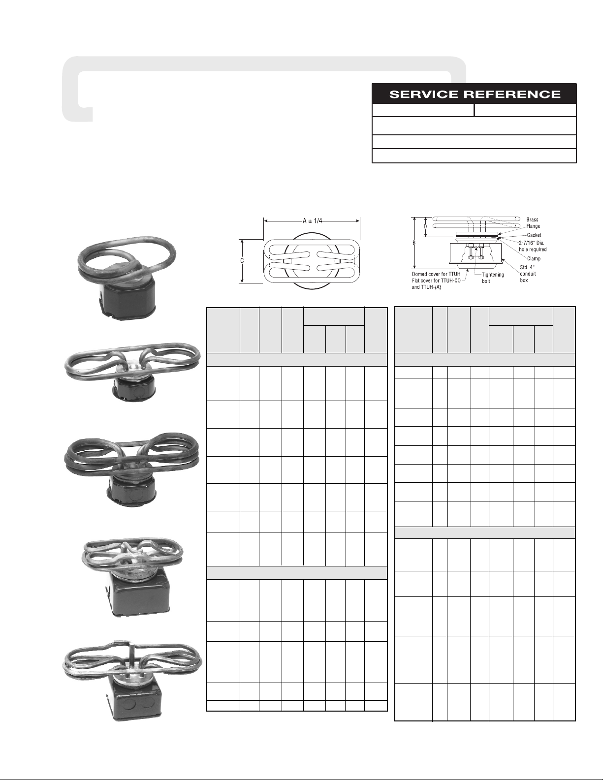
Dimensions (In.)
Extends
Overall Into
Length Tank
Model Volts kW W/In
2
ABCD‡
TTUH — 1 Phase — 3” min. liquid depth
TTUH-10A 120 1 42 6-3/4 4-9/16 4-1/4 2-5/16
TTUH-15A 120 1.5 57 6-3/4 4-9/16 4-1/4 2-5/16
TTUH-15A 208 1.5 57 6-3/4 4-9/16 4-1/4 2-5/16
TTUH-15A 240 1.5 57 6-3/4 4-9/16 4-1/4 2-5/16
TTUH-20A 120 2 57 6-3/4 4-9/16 4-1/4 2-5/16
TTUH-20A 208 2 57 6-3/4 4-9/16 4-1/4 2-5/16
TTUH-20A 240 2 57 6-3/4 4-9/16 4-1/4 2-5/16
TTUH-25A 120 2.5 58 6-3/4 4-9/16 4-1/4 2-5/16
TTUH-25A 208 2.5 58 6-3/4 4-9/16 4-1/4 2-5/16
TTUH-25A 240 2.5 58 6-3/4 4-9/16 4-1/4 2-5/16
TTUH-30A 120 3 55 6-3/4 4-9/16 4-1/4 2-5/16
TTUH-30A 208 3 55 6-3/4 4-9/16 4-1/4 2-5/16
TTUH-30A 240 3 55 6-3/4 4-9/16 4-1/4 2-5/16
TTUH-40A 120 4 53 9-1/2 4-9/16 4 1-3/8
TTUH-40A 208 4 53 9-1/2 4-9/16 4 1-3/8
TTUH-40A 240 4 53 9-1/2 4-9/16 4 1-3/8
TTUH-50 208 5† 39 12-3/4 4-9/16 4 1-11/16
TTUH-50 240 5† 39 12-3/4 4-9/16 4 1-11/16
TTUH-60 208 6† 42 14-1/2 4-9/16 4 1-11/16
TTUH-60 240 6† 42 14-1/2 4-9/16 4 1-11/16
TTUH-70 208 7† 49 14-1/2 4-9/16 4 1-11/16
TTUH-70 240 7† 49 14-1/2 4-9/16 4 1-11/16
TTUH — 3 Phase — 3” min. liquid depth
TTUH-303 208 3† 55 8-3/4 4-5/8 3-1/8 1-15/16
TTUH-303 240 3† 55 8-3/4 4-5/8 3-1/8 1-15/16
TTUH-403 208 4† 74 8-3/4 4-5/8 3-1/8 1-15/16
TTUH-403 240 4† 74 8-3/4 4-5/8 3-1/8 1-15/16
TTUH-408 480 4† 74 8-3/4 4-5/8 3-1/8 1-15/16
TTUH-503 208 5† 73 11 4-5/8 3-1/8 1-15/16
TTUH-503 240 5† 73 11 4-5/8 3-1/8 1-15/16
TTUH-603 208 6† 67 11-1/16 5 4-1/16 2-3/8
TTUH-603 240 6† 67 11-1/16 5 4-1/16 2-3/8
TTUH-603 480 6† 67 11-1/16 5 4-1/16 2-3/8
TTUH-703 208 7† 78 11-1/16 5 4-1/16 2-3/8
TTUH-703 240 7† 78 11-1/16 5 4-1/16 2-3/8
TTUH-803 208 8† 69 11-1/8 5 4-1/16 2-3/8
TTUH-803 240 8† 69 11-1/8 5 4-1/16 2-3/8
TTUH-1203 240 12† 98 17-3/4 5 4-1/16 2-3/8
(Supersedes PD400-14)
PD400-15
TTUH
161-048415-001
OCTOBER, 2000
4
RENEWAL PARTS IDENTIFICATION
Installation, Operation
and
DATE
SALES
REFERENCE
DIVISION SECTION
Chromalox
®
Type TTUH and TTUH-CO URN Heaters
Dimensions (In.)
Extends
Overall Into
Length Tank
Model Volts kW W/In
2
ABCD‡
TTUH-CO — 1 Phase with cutout — 3-1/4” min. liquid depth
TTUH-CO-10 120 1 42 7-7/16 4-8/16 3-1/16 1-3/8
TTUH-CO-15 120 1.5 62 7-7/16 4-13/16 3-1/16 2-3/8
TTUH-CO-15 208 1.5† 62 7-7/16 4-13/16 3-1/16 2-3/8
TTUH-CO-15 240 1.5† 62 7-7/16 4-13/16 3-1/16 2-3/8
TTUH-CO-20 208 2 60 9-7/16 4-13/16 3-1/16 2-1/8
TTUH-CO-20 240 2 60 9-7/16 4-13/16 3-1/16 2-1/8
TTUH-CO-25 208 2.5 40 6-3/4 4-13/16 3-1/16 2-1/8
TTUH-CO-25 240 2.5 40 6-3/4 4-13/16 3-1/16 2-1/8
TTUH-CO-30 208 3 55 6-3/4 4-13/16 3-1/16 2-1/8
TTUH-CO-30 240 3 55 6-3/4 4-13/16 3-1/16 2-1/8
TTUH-CO-40 208 4† 64 9-1/2 4-13/16 3-1/16 2-1/8
TTUH-CO-40 240 4† 64 9-1/2 4-13/16 3-1/16 2-1/8
TTUH-CO-50 208 5† 70 12-3/4 5-3/8 4 2-11/16
TTUH-CO-50 240 5† 70 12-3/4 5-3/8 4 2-11/16
TTUH-CO-60 208 6† 73 14-1/2 5-3/8 4 2-11/16
TTUH-CO-60 240 6† 73 14-1/2 5-3/8 4 2-11/16
TTUH-CO-70 240 7† 85 14-1/2 5-3/8 4 2-11/16
TTUH-CO — 3 Phase with cutout — 3-1/2” min. liquid depth
TTUH-CO-303 208 3 55 8-3/4 5-13/16 3-1/8 2-23/32
TTUH-CO-303 240 3 55 8-3/4 5-13/16 3-1/8 2-23/32
TTUH-CO-403 208 4 74 8-3/4 5-13/16 3-1/8 2-23/32
TTUH-CO-403 240 4 74 8-3/4 5-13/16 3-1/8 2-23/32
TTUH-CO-503 208 5 73 11 5-13/32 3-1/8 2-23/32
TTUH-CO-503 240 5 73 11 5-13/32 3-1/8 2-23/32
TTUH-CO-503 480 5 73 11 5-13/32 3-1/8 2-23/32
TTUH-CO-603 208 6 72 11-1/16 5-3/4 4-1/16 3
TTUH-CO-603 240 6 72 11-1/16 5-3/4 4-1/16 3
TTUH-CO-703 208 7 78 11-1/16 5-3/4 4-1/16 3
TTUH-CO-703 240 7 78 11-1/16 5-3/4 4-1/16 3
TTUH-CO-703 480 7 78 11-1/16 5-3/4 4-1/16 3
TTUH-CO-803 208 8 69 14-1/2 5-3/4 4-1/16 3
TTUH-CO-803 240 8 69 14-1/2 5-3/4 4-1/16 3
TTUH-CO-803 480 8 69 14-1/2 5-3/4 4-1/16 3
TTUH-CO-903 208 9 78 14-1/2 5-3/4 4-1/16 3
TTUH-CO-903 240 9 78 14-1/2 5-3/4 4-1/16 3
TTUH-CO-903 480 9 78 14-1/2 5-3/4 4-1/16 3
TTUH-CO-1003 208 10 82 17-11/16 5-3/4 4-1/16 3
TTUH-CO-1003 240 10 82 17-11/16 5-3/4 4-1/16 3
TTUH-CO-1003 480 10 82 17-11/16 5-3/4 4-1/16 3
TTUH-CO-1203 240 12 98 17-11/16 5-3/4 4-1/16 3
TTUH-CO-1203 480 12 98 17-11/16 5-3/4 4-1/16 3
Specifications — TTUH Specifications — TTUH-CO
‡ Minimum liquid level should be maintained at 1/2” above D dimension.
† Brazed terminal construction; cannot be wired for 3 heats.
‡ Minimum liquid level should be maintained at 1/2” above D dimension.
† Brazed terminal construction; cannot be wired for 3 heats.
TTUH-20A
TTUH-50
TTUH-CO-30
TTUH-CO-503
© 2010 Chromalox, Inc.
TTUH-703WSS
Page 2

2
FIRE/EXPLOSION HAZARD. This heater is not
intended for use in hazardous atmospheres where
flammable vapors, gases, liquids or other combustible atmospheres are present as defined in the
National Electrical Code. Failure to comply can
result in personal injury or property damage.
Chromalox TTUH and TTUH-CO food equipment heaters are
ideal for coffee urns, steam tables, kettles, humidifiers and other
commercial uses.
Heater Construction Characteristics
A. An opening of 2-7/16” in diameter in the bottom of the tank is
required to insert the heater.
B. High watt density.
C. 4” conduit box is mounted to the tank by a tightening bolt.
The system designer is responsible for the safety
of this equipment and should install adequate
back-up controls and safety devices with their
electric heating equipment. Where the consequences of failure could result in personal injury or
property damage, back-up controls are essential.
GENERAL
ELECTRIC SHOCK HAZARD. Disconnect all power
before installing or servicing heater. Failure to do
so could result in personal injury or property damage. Heater must be installed by a qualified person
in accordance with the National Electrical Code,
NFPA 70.
FIRE HAZARD. Since heaters are capable of developing high temperatures, extreme care should be
taken to:
A. Avoid mounting heaters in an atmosphere con-
taining combustible gases and vapors.
B. Avoid contact between heaters and combustible
materials.
C. Keep combustible materials far enough away to
be free of the effects of high temperature.
D. Keep heater immersed at all times.
INSTALLATION
Page 3

3
Note: Mount heater in horizontal position.
1. Cut a hole 2-7/16” in diameter in bottom of tank unless already
done.
2. Insert heater with gasket. (Use sealer if tank wall is corroded.)
3. Mount the combination terminal enclosure and clamp over the ele-
ment flange. (On 3 phase, first remove center jumper strap.)
4. Use bolt to draw mounting flange tight to tank bottom. (Reconnect
jumper strap on 3 phase.)
5. For connecting heaters, see wiring diagrams.
6. 120V elements can be connected in series for high voltage opera-
tion.
Figure 2
1. Remove cover.
2. Loosen set screw with 5/64” balldriver L-wrench. (Alan wrench).
3. Remove thermal cutout by pulling directly out.
4. Remove enclosure flange assembly by removing 5/16” socket
head cap screw in center.
5. Insert element and gasket in tank opening (use sealer if tank wall
is corroded).
6. Replace enclosure flange assembly and the 5/16” socket head
cap screw.
7. Push cutout into place. Be sure the thermal cutout is properly
located and seated on the conductor rod. (See Figures 3A & 4A).
8. Secure cutout to the conductor rod with the set screw. (See Figure
3A).
9. Make sure fully insulated 1/4” female spade connectors are used
when connecting to the thermal cutout.
10. On all single phase units less than 3kW – attach power leads to T1
& T2 (see Figure 4A) and connect cutout lead to one terminal on
the cutout.
Note: Single phase heaters 3kW and above and all three phase
models require the use of a suitable magnetic contactor. (Supplied
by customer).
11. On all TTUH-CO Three Phase Delta Units – Twist 1L3 & 2L3 leads
together to create L3, then, attach power leads to L1, L2 & L3.
Connect coutout to relay or contactor coil. (See Figures 5A & 9)
12. Replace cover with the “push to reset” hole directly over the
cutout.
13. Refer to the main portion of the instruction, operation and maintenance instructions for all other information.
14. The thermal cutout on the TTUH-CO provides run dry burn-out
protection only. Partial immersion of the elements while energized
can shorten element life. The cutout is a safety device only &
should not be used continuously as a low-liquid-level control.
15. Should the thermal cutout trip during operation, disconnect all
power to the heater before resetting.
16. Apply the manual reset locator label 170-122103-111, in view, to help
locate the manual reset button. See procedure 223-304407-007.
TTUH TTUH-CO
Heating
Element
Gasket
Center
Bolt
Pigtail Leads TTUH-A
Series (See Fig. 12)
Spacer
Tank Wall
Washer
Nut
Terminal
Box
Cover
Cover
Screws
Terminal
Box
Enclosure
ø 3/16 Hole
Set Screw for TTUH-CO
Using Alternate Cutout
P/N 248-049593-026
Mounting Clamp for
TTUH-CO Using
Alternate Cutout
P/N 056-019044-003
5/64" Balldriver
L-Wrench (Alan Wrench)
"Customer Supplied"
INSTALLATION
Cutout Lead
Fully Insulated
Female Spade
Connector
T1
T2
Make sure the
cutout is seated
all the way down
on the connector
rod
Alternate Thermal
Cutout for TTUH-CO
P/N 300-012172-006
Customer Supplied
Connector
L3
1L3
2L3
L1
L2
Cutout
240 Volts
(Max.)
Manual Reset Button
(Disconnect all power
before resetting)
Connect in Series
with Relay or
Contactor Coil
Figure 3
Figure4
Figure 5
Page 4

4
ELECTRIC SHOCK HAZARD. Any installation involving electric heaters must be performed by a qualified person and must be effectively grounded in
accordance with the National Electrical Code to
eliminate shock hazard.
1. Be sure line voltage matches heater voltage (on nameplate).
2. Electric wiring to heater must be installed in accordance with
the National Electrical Code and with local codes by a qualified person.
CAUTION: Use copper conductors only.
3. When element wattages are not equal, heaters must not be connected in series.
4. Make necessary wiring connections as shown on wiring diagram (Figures 6 thru 11).
WIRING
WIRING DIAGRAMS
Figure 6 — TTUH 1 Phase
Figure 7 — TTUH 3 Phase Delta Figure 8 — TTUH-CO 1 Phase Figure 9 — TTUH-CO 3 Phase Delta
Figure 10 — TTUH 3 Phase Wye Figure 11 — TTUH-CO 3 Phase Wye
Note: Contactors shown in Figure 7, 8, 9, 10 and 11 are supplied by customer.
208, 240 & 480V
Note: All 3 phase heaters require the
use of a contactor.
L2
L3
T3
T2
T1
L1
C1
C2
120, 208 & 240V
Note: Single phase heaters 3 kW and
above require the use of a contactor.
C1
C2
L1
L2
T2
T1
208, 240 & 480V
Note: All 3 phase heaters require the
use of a contactor.
T1
T2
T3
L2
L3
L1
C1
C2
L2
L1
1 Heat-Parallel —
120, 208 & 240V
#10 Studs & Cup Washers Or
Cup Washers
L2
L1
Common
120, 208 & 240V — 3 Heat
#10 Studs & Cup Washers Or
Cup Washers
Jump Strap
120V Element
240V Series Connected
T1
T2
T3
L2
L3
L1
C1
C2
208, 240 & 480V
Note: All 3 phase heaters require the
use of a contactor.
T1
T2
T3
L2
L3
L1
C1
C2
208, 240 & 480V
Note: All 3 phase heaters require the
use of a contactor.
1
4
3
2
1
4
3
2
1
4
3
2
L2
L1
Medium
L2
L1
Low
L2
L1
Green
Ground
120, 208 & 240V - 3 Heat
Figure 12 — TTUH - (A) 1 Phase
High
Page 5

MAINTENANCE
ELECTRIC SHOCK HAZARD. Disconnect all power
before installing or servicing heater or resetting
the manual reset button. Failure to do so could
result in personal injury or property damage.
Heater must be installed by a qualified person in
accordance with the National Electrical Code.
NFPA 70.
IMPORTANT: It is the responsibility of the purchaser of the heater to make the ultimate choice of
sheath material based upon his knowledge of the
chemical composition of the corrosive solution,
character of the materials entering the solution,
and controls which he maintains on the process.
1. Heaters should be checked periodically for coatings and corrosion and cleaned if necessary.
2. Tank should be checked regularly for sediment around the
heater. Sediment can act as an insulator and shorten heater life.
3. Check for loose terminal connections.
4. If corrosion is indicated in the terminal enclosure, check termi-
nal box gasket and replace if necessary, and check conduit layout to correct conditions that allow corrosion to enter the terminal housing.
5. Clean terminal ends of all contamination.
OPERATION
1. Do not operate at voltages in excess of that stamped on the
heater since excess voltage will shorten heater life.
IMPORTANT: Mount heater in the tank so the liquid
level will always be above the effective heated portion of the heater. Provide expansion tank if necessary.
Note: The Thermal cutout on the TTUH-CO provides run dry
burn-out protection only. Partial immersion of the elements while
energized can shorten element life. The cutout is a safety device
only and should not be used continuously as a low-liquid-level
control.
6
Page 6

2150 N. RULON WHITE BLVD., OGDEN, UT 84404
Phone: 1-800-368-2493 www.chromalox.com
00 - 000
TA - X0 - EF
Litho in U.S.A.
RENEWAL PARTS IDENTIFICATION
THERMAL CUTOUT
For TTUH-CO only
GASKET
For all heaters
P/N 132-010737-001
MOUNTING CLAMP
For TTUH
(1 and 3 Phase)
P/N 056-016147-001
For TTUH-CO
P/N 056-019044-003
MOUNTING BOLT
For all heaters
5/16 x 1” Lg. Hex
Socket head cap screw
P/N 345-041953-001
Set Screw P/N 248-049593-026
PCN 427725
Note: New cutout will not work
with old style TTUH-CO models.
Limited Warranty:
Please refer to the Chromalox limited warranty applicable to this product at
http://www.chromalox.com/customer-service/policies/termsofsale.aspx.
 Loading...