

Chromalox ADHT-005, ADH-010, ADHT-010, ADH-015, ADHT-015 Installation Operation and RENEWAL PARTS IDENTIFICATION
...Page 1
Chromalox
Type ADH and ADHT
Air Duct Heaters
© 2008 Chromalox, Inc.
No. Mtg.
Approx. Approx. Holes
Net. Wt. Net. Wt. No. 9/32” No.
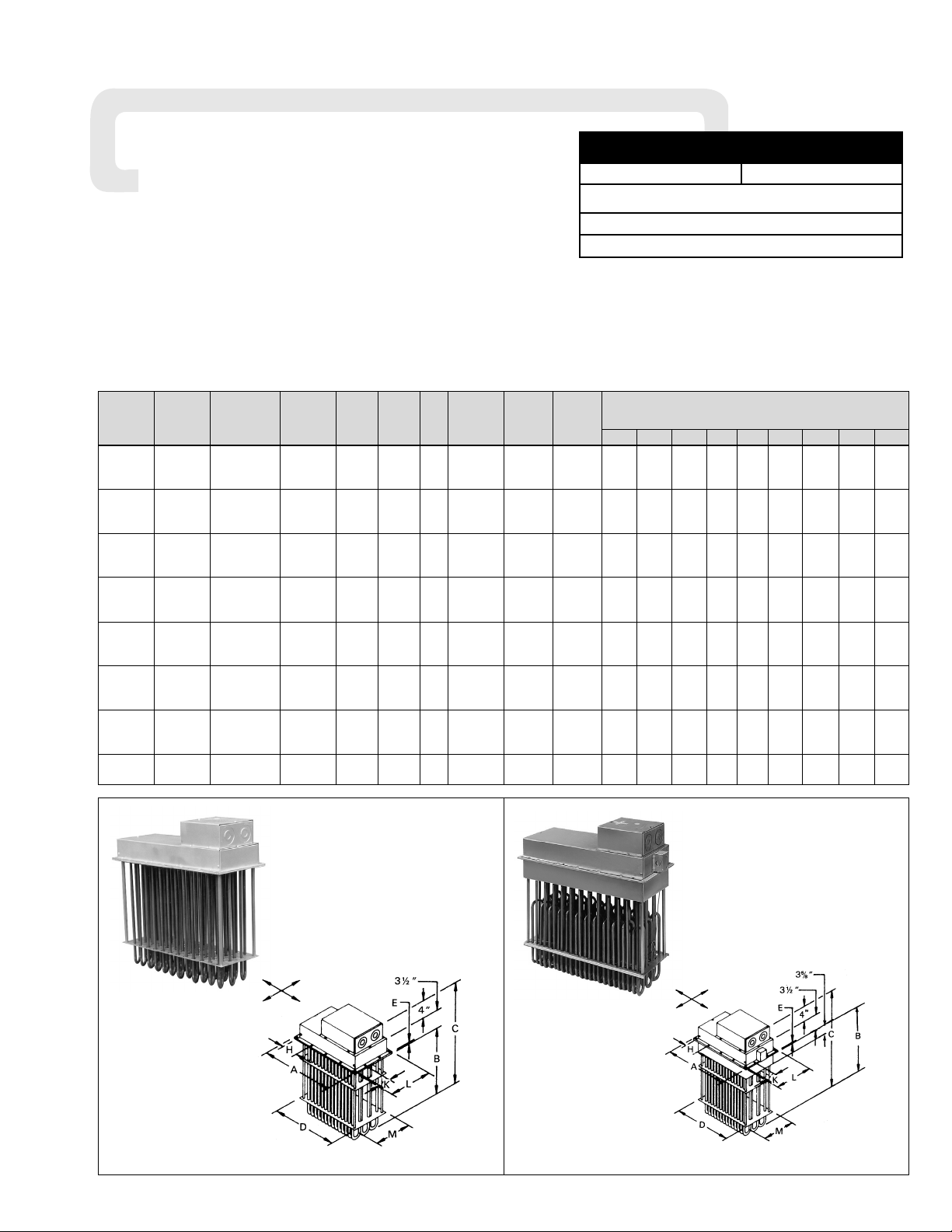
Dimensions (In.)
Model (Lbs.) Model (Lbs.) Volts Phase kW Elements Dia. Circuits A B C D E H K L M
ADH-005 8 ADHT-005 10 480 3 5 3 10 1 5-5/8 20-3/8 28-1/8 4 1/4 2-1/2 3-1/2 11-1/8 9-1/2
ADH-010 15 ADHT-010 20 480 3 10 6 10 1 7-5/8 20-3/8 28-1/8 6 1/4 3-1/2 3-1/2 11-1/8 9-1/2
ADH-015 25 ADHT-015 30 480 3 15 9 12 1 9-5/8 20-3/8 28-1/8 8 1/4 3 3-1/2 11-1/8 9-1/2
ADH-020 35 ADHT-020 40 480 3 20 12 14 1 11-5/8 20-3/8 28-1/8 10 1/4 2-3/4 3-1/2 11-1/8 9-1/2
ADH-025 40 ADHT-025 50 480 3 25 15 14 1 13-5/8 20-3/8 28-1/8 12 1/4 3-1/4 3-1/2 11-1/8 9-1/2
ADH-030 55 ADHT-030 65 480 3 30 18 14 1 15-5/8 20-3/8 28-1/4 14 3/8 3-3/4 3-1/2 11-1/8 9-1/2
ADH-035 65 ADHT-035 80 480 3 35 21 14 1 17-5/8 20-3/8 28-1/4 16 3/8 4-1/4 3-1/2 11-1/8 9-1/2
ADH-040 70 ADHT-040 90 480 3 40 24 14 2 19-5/8 20-3/8 28-1/4 18 3/8 4-3/4 3-1/2 11-1/8 9-1/2
ADH-045 80 ADHT-045 100 480 3 45 27 14 2 21-5/8 20-3/8 28-1/4 20 3/8 5-1/4 3-1/2 11-1/8 9-1/2
ADH-050 90 ADHT-050 110 480 3 50 30 14 2 23-5/8 20-3/8 28-1/4 22 3/8 5-3/4 3-1/2 11-1/8 9-1/2
ADH-060 105 ADHT-060 130 480 3 60 36 18 2 27-5/8 20-3/8 28-1/4 26 3/8 4-1/2 3-1/2 11-1/8 9-1/2
ADH-080 140 ADHT-080 175 480 3 80 48 22 4 35-5/8 20-3/8 28-1/4 34 3/8 4-3/8 3-1/2 11-1/8 9-1/2
ADH-090 160 ADHT-090 200 480 3 90 54 22 5 39-5/8 20-3/8 28-1/4 38 3/8 4-7/8 3-1/2 11-1/8 9-1/2
ADH-100 175 ADHT-100 220 480 3 100 60 22 5 43-5/8 20-3/8 28-1/4 42 3/8 5-3/8 3-1/2 11-1/8 9-1/2
— — ADHT-120 205 480 3 120 36 18 4 27-5/8 35 42-7/8 26 3/8 4-1/2 3-1/2 11-1/8 9-1/2
ADH-144 165 — — 480 3 144 48 22 4 35-5/8 35 42-7/8 34 3/8 4-3/8 3-1/2 11-1/8 9-1/2
— — ADHT-160 270 480 3 160 48 22 8 35-5/8 35 42-7/8 34 3/8 4-3/8 3-1/2 11-1/8 9-1/2
ADH-162 185 — — 480 3 162 54 22 6 39-5/8 35 42-7/8 38 3/8 4-7/8 3-1/2 11-1/8 9-1/2
— — ADHT-180 305 480 3 180 54 22 6 39-5/8 35 42-7/8 38 3/8 4-7/8 3-1/2 11-1/8 9-1/2
ADH-216F 240 — — 480 3 216 72 22 6 27-5/8 35 42-7/8 26 3/8 4-1/2 3-7/8 20 18-3/8
— — ADHT-240F 400 480 3 240 72 22 8 27-5/8 35 42-7/8 26 3/8 4-1/2 3-7/8 20 18-3/8
ADH-270F 300 — — 480 3 270 90 22 8 33-5/8 35 42-7/8 32 3/8 5-1/2 3-7/8 20 18-3/8
— — ADHT-300F 500 480 3 300 90 22 10 33-5/8 35 42-7/8 32 3/8 5-1/2 3-7/8 20 18-3/8
Specifications — Table A
Figure 1 — Dimensions Figure 2 — Dimensions
Type ADH Type ADHT
Airflow
Direction
Airflow
Direction
®
Installation Operation
and
DIVISION 4 SECTION ADH
SALES
REFERENCE
(Supersedes PF438-2)
PF438-3
161-057949-001
SERVICE REFERENCE
RENEWAL PARTS IDENTIFICATION
MARCH, 1999
DATE
Page 2
WARNING: Hazard of Electric Shock. Disconnect all
power before installing heater.
1. Locate and position heater in duct in accordance with both
process requirements and recommendations given.
2. Refer to Figures 1 and 2, layout “D” and “M” dimensions on
duct mounting face established in step 1.
3. With tools suitable for sheet metal work, cut layout opening in
duct.
4. In general, heaters less than 35 pounds in weight may be mounted
directly in opening without additional duct reinforcement if duct
installation and condition permits. To fasten heater to duct wall use
#14 pan or round head self-tapping screws. The flange mounting
gasket supplied with the heater is recommended for insertion
between heater flange and duct to minimize air leakage.
5. For heater weights greater than 35 pounds (see Specifications
Table A, page 1) due consideration should be given to; (a)
mechanically strengthening duct work with, for example, angle
irons or chains (see Figure 5), and (b) heat insulating duct line
in immediate area of heater location to prevent excessive heat
loss. Consult your local sheet metal contractor.
6. In high ambient temperature operations, least corrosive action
and least oxidation to the terminals will occur if the heaters are
mounted with the terminals in the coolest possible ambient,
usually on the bottom or side of the duct.
A. Minimum duct size is “A” or “L” dimension +3/8” and “B”
dimension +1-5/8”.
WARNING: This heater is not intended for use in hazardous atmospheres where flammable vapors, gases,
liquids or other combustible atmospheres are present
as defined in the National Electrical Code. Failure to
comply can result in explosion or fire.
1. Heater construction characteristics —
A. Alloy sheathed tubular elements, .475” diameter
B. Steel flange
C. Stainless steel support construction
D. High temperature alloy terminals and connections
E. Replaceable individual heating elements
F. Wiring terminals located outside the heated zone
2. Maximum Temperatures — Types ADH and ADHT process
air heaters can generally be used at the following maximum
temperatures shown, provided the minimum air velocity is
maintained uniformly through the heater.
CAUTION: Do not energize heater in air with a
velocity less than 1 Ft. Per Second.
3. The heater may be bolted to the duct with the terminal housing
and flange at the top, at either side or at the bottom.
4. Several heaters may be mounted in tandem so long as proper
controls are used to limit the maximum temperature attained.
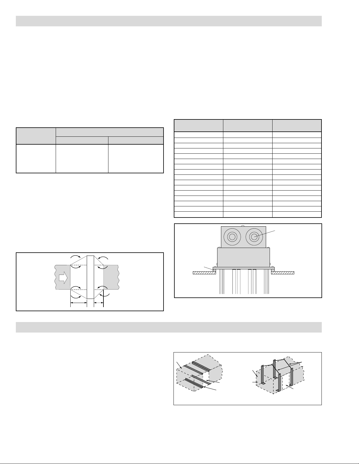
5. Installation with duct transitions in some air distribution systems, the duct heater may be considerably larger than the ductwork and the duct area must be increased by a sheet metal transition. The slope of the transformation piece on the upstream
side of the equipment is limited to 30° as indicated in Figure 3.
On the leaving side, the slope should not be more than 45°.
6. Use moisture proof terminal cover in atmospheres bearing corrosive fumes or excessive moisture.
7. Use explosion resistant heaters in explosive atmospheres and
reduce current rating to elements.
8. Gas tight design — Achieved by the use of threaded fittings
with fiber washers to attach heating elements to flange — pre
vents leakage of ducted air into terminal housing.
9. Overtemperature protection — Thermocouple fastened to the element sheath surface and wired to a terminal block can be provided for accurate overheat protection (standard on ADHT models).
10. Flange mounting gasket — Packed separately with each duct
heater to minimize air leakage between the flange and air duct.
Refer to Table B and Figure 3.
GENERAL
Max. Outlet Air Temp. (˚F)
Air Velocity
(Ft./Sec.) ADH ADHT
4 800 1050
9 800 1100
16 800 1150
25 800 1200
36 800 1200
Flange Gasket Used On
Part No. Flange Size ADH and ADHT
168-055429-001 11-1/8 x 5-5/8 5 kW
168-055429-002 11-1/8 x 7-5/8 10 kW
168-055429-003 11-1/8 x 9-5/8 15 kW
168-055429-004 11-1/8 x 11-5/8 20 kW
168-055429-005 11-1/8 x 13-5/8 25 kW
168-055429-006 11-1/8 x 15-5/8 30 kW
168-055429-007 11-1/8 x 17-5/8 35 kW
168-055429-008 11-1/8 x 19-5/8 40 kW
168-055429-009 11-1/8 x 21-5/8 45 kW
168-055429-010 11-1/8 x 23-5/8 50 kW
168-055429-011 11-1/8 x 27-5/8 60, 120 kW
168-055429-013 11-1/8 x 35-5/8 80, 144, 160 kW
168-055429-014 11-1/8 x 39-5/8 90, 162, 180 kW
168-055429-015 11-1/8 x 43-5/8 100 kW
168-055429-017 20 x 27-5/8 216, 240 kW
168-055429-018 20 x 33-5/8 270, 300 kW
Specifications — Table B
Figure 3
Figure 4
INSTALLATION
Figure 5
2
30"
45˚
Max
2-1/2" x 1-1/4" x 3/4"
Knockouts
Flange
Mounting
Gasket
Air
Flow
4 Ft. Min.
Duct Heater
45˚
30˚
Max
4 Ft. Min.
Duct Wall
uct
Duct
Heater
Opening
Angle Iron
Metal
Strapping
Chains
Heater Opening
Page 3
7. DANGER: Hazard of Fire. Since these heaters are
capable of developing high temperatures, extreme
care should be taken to:
A. Avoid installing heaters in an atmosphere containing com-
bustible gases and vapors.
B. Avoid contact between heater and combustible material.
C. Keep combustible materials far enough away to be free of
the effects of high temperatures.
INSTALLATION
Temperature Control Instructions
1. A Chromalox thermal cutout or thermostat is recommended for
overheat protection and control of heater and process. Consult
local Chromalox representative.
2. In general, place thermostat sensing element close to the heating elements, near top of duct, at right angles to the direction of
air flow, and on the downstream side of the heater. Thermostat,
provided with a manual reset button, is separately mounted.
3. For heater protection, the indicated maximum temperature of
the control unit should be 50°F less than the actual maximum
air temperature that will be permitted, to allow for overshoot.
4. Single circuit heater elements may be wired into two circuits to
allow for partial heating and control. It is important to have
thermal control wired into all electric power circuits, so that all
elements may be protected from overheat.
Figure 6 Figure 7
WARNING: Hazard of Electric Shock. Any installation involving electric heaters must be effectively
grounded in accordance with the National
Electrical Code to eliminate shock hazard.
1. All wiring should be done in accordance with National Electrical
Code and with local codes by a qualified person.
2. Connect air heaters to same line voltage, phase, and frequency
as on heater nameplate.
3. Teflon insulated nickel plated copper wire or bus bar is recommended for power connections to heater terminals and for
wiring runs in heated zones. When ambient temperature in
heated zone exceeds that for which insulated wire is recommended use bare nickel-plated copper with porcelain beads,
tubing or bus bar. Consult local Chromalox representative.
4. Users should install adequate back-up controls and safety
devices with their electric heating equipment. Selection of controls, thermostat, SCR units, contactors and etc. depends on the
degree of accuracy required, reliability, electrical rating of
heater and economic considerations.
5. Below is an example of a standard ADH-015, 480V 3 Ø 15 kW,
wired with recommended back-up controls. (Figure 8)
6. Individual terminal blocks with threaded stud type terminals
are provided for each circuit to permit quick positive attachment of circuit wiring conductors (one terminal block per circuit). (Figure 9)
WIRING
Figure 8
Figure 9
ADH-015, 15 kW 480V 3ø, 1 Circuit
(9) - 480V, 1667 Watt Elements
3
Duct
Air
Air
Insulation
(3" max.)
Standoff Collar
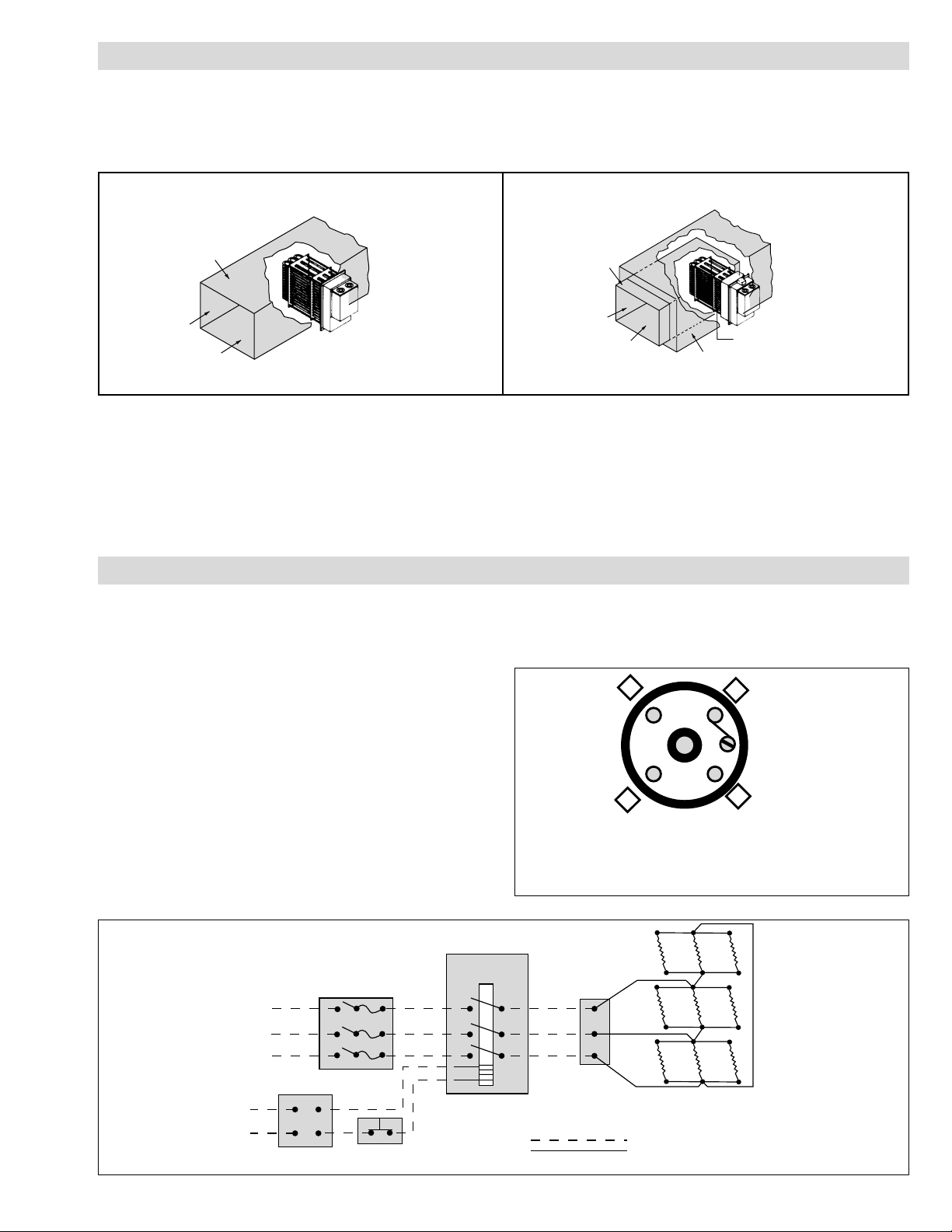
ADH Low temperature duct heaters — can be fastened directly to the sheet metal duct
work with bolts or sheet metal screws.
ADHT High temperature duct heaters — are generally mounted on field fabricated stand
off supports from the ductwork to position the heater such that the 3” insulation housing
is in the same plane as the duct insulation.
Duct
Air
Air
Fused
Switch
L1
L2
L3
Magnetic
Contactor
Terminal
L1
✸
L2
Terminal block
(303-027852-001)
X Circuit label indicated here.
Block
L1
L2
L3
G
L3
Control
Voltage
120 or 240V
Control Switch
Thermostat
ADH-015
Customer Supplied Wiring
Factory Supplied Wiring
Page 4

ADH-005, ADHT-005 ADH-010, ADHT-010 ADH-015, ADHT-015
ADH-020, ADHT-020 ADH-025, ADHT-025
ADH-030, ADHT-030 ADH-035, ADHT-035
WARNING: Users should install adequate controls
and safety devices with their electric heating equipment. Where the consequences of failure may be
severe, back-up controls are essential.
Although the safety of the installation is the responsibility of the user, Chromalox will be glad to make
equipment recommendations.
1. Do not operate heater at voltages in excess of that stamped on
the heater since excess voltage will shorten heater life.
OPERATION
WARNING: Hazard of Severe Shock. Disconnect all
power to heater before servicing or replacing heaters.
1. Periodically clean terminals and terminal covers of dust and
corrosion to maintain good electrical connections and to permit
rapid heat dissipation. Use airblast, and be careful to avoid
damage to mica insulation.
2. Check for loose terminal connections.
MAINTENANCE
ADH-005, ADHT-005, ADH-010, ADHT-010,
ADH-015, ADHT-015, ADH-020, ADHT-020,
ADH-025, ADHT-025, ADH-030, ADHT-030,
ADH-035, ADHT-035 . . . . . . . . . . . . . . . . . . . . . . . . . . . . . . . . .4
ADH-040, ADHT-040, ADH-045, ADHT-045,
ADH-050, ADHT-050, ADH-060, ADHT-060,
ADH-080, ADHT-080, ADH-090, ADHT-090,
ADH-100, ADHT-100 . . . . . . . . . . . . . . . . . . . . . . . . . . . . . . . . .5
ADHT-120, ADH-144, ADHT-160, ADH-162,
ADHT-180, ADH-216F, ADHT-240F, ADH-270F,
ADH-300F . . . . . . . . . . . . . . . . . . . . . . . . . . . . . . . . . . . . . . . . . .6
WIRING DIAGRAMS
1 Circuit, 3 Elements per Heater 1 Circuit, 6 Elements per Heater 1 Circuit, 9 Elements per Heater
AL1
AL2
AL3
AL1
AL3
AL2
AL1
AL2
AL3
1 Circuit, 12 Elements per Heater 1 Circuit, 15 Elements per Heater
AL1
AL2
AL3
AL1
AL2
AL3
1 Circuit, 18 Elements per Heater 1 Circuit, 21 Elements per Heater
AL1
AL2
AL3
AL1
AL2
AL3
Circuit ACircuit ACircuit A
Circuit A
Circuit A
Circuit A
Circuit A
4
Page 5

WIRING DIAGRAMS
ADH-040, ADHT-040 ADH-045, ADHT-045
2 Circuits per Heater, Circuit A, B, 12 Elements per Circuit,
24 Elements per Heater
AL1, BL1
AL2, BL2
AL3, BL3
Typical Circuit
AL1
AL2
AL3
BL1
BL2
BL3
2 Circuits per Heater, Circuit A, 15 Elements,
Circuit B, 12 Elements, 27 Elements per Heater
Circuit A Circuit B
ADH-050, ADHT-050
2 Circuits per Heater, Circuit A, B 18 Elements, Circuit C, 12 Elements, 30 Elements per Heater
AL1, BL1
AL2, BL2
AL3, BL3
CL1
CL2
CL3
Circuit A, B
Circuit C
Typical Circuit
ADH-060, ADHT-060 ADH-080, ADHT-080
2 Circuits per Heater, Circuit A, B,
18 Elements per Circuit, 36 Elements per Heater
AL1, BL1
AL2, BL2
AL3, BL3
ADH-090, ADHT-090 ADH-100, ADHT-100
4 Circuits per Heater, Circuit A, B, C, D,
12 Elements per Circuit, 48 Elements per Heater
AL1, BL1, CL1, DL1
AL2, BL2, CL2, DL2
AL3, BL3, CL3, DL3
Circuit A, B, C, D
5
Typical Circuit
EL2
AL1, BL1, CL1, DL1
EL1
EL3
AL2, BL2, CL2, DL2
AL3, BL3, CL3, DL3
Circuit E
5 Circuits per Heater, Circuit A, B, C, D, 12 Elements per Circuit,
Circuit E, 6 Elements, 54 Elements per Heater
5 Circuits per Heater, Circuit A, B, C, D, E,
12 Elements per Circuit, 60 Elements per Heater
AL1, BL1, CL1, DL1, EL1
AL2, BL2, CL2, DL2, EL2
AL3, BL3, CL3, DL3, EL3
Typical Circuit
Page 6

AL1, BL1, CL1, DL1
AL2, BL2, CL2, DL2
AL3, BL3, CL3, DL3
4 Circuits per Heater, Circuit A, B, C, D,
12 Elements per Circuit, 48 Elements per Heater
WIRING DIAGRAMS
ADHT-120 ADH-144
ADH-160 ADH-162, ADHT-180
ADH-216F ADHT-240F ADH-270F ADH-300F
4 Circuits per Heater, Circuit A, B, C, D,
9 Elements per Circuit, 36 Elements per Heater
AL1, BL1, CL1, DL1
AL2, BL2, CL2, DL2
AL3, BL3, CL3, DL3
6
Typical Circuit Typical Circuit
8 Circuits, Circuit A, B, C, D, E, F, G, H,
6 Elements per Circuit, 48 Elements per Heater
AL1, BL1, CL1, DL1, EL1, FL1, GL1, HL1
AL2, BL2, CL2, DL2, EL2, FL2, GL2, HL2
AL3, BL3, CL3, DL3, EL3, FL3, GL3, HL3
Typical Circuit
6 Circuits, Circuit A, B, C, D, E, F,
9 Elements per Circuit, 54 Elements per Heater
Typical Circuit
AL1, BL1, CL1, DL1, EL1, FL1
AL2, BL2, CL2, DL2, EL2, FL2
AL3, BL3, CL3, DL3, EL3, FL3
Typical Circuit
Typical Circuit
8 Circuits,
Circuit A, B, C, D, E, F, G, H,
9 Elements per Circuit, 72
Elements per Heater
6 Circuits,
Circuit A, B, C, D, E, F,
12 Elements per Circuit, 72
Elements per Heater
AL1, BL1, CL1,
DL1, EL1, FL1
AL2, BL2, CL2,
DL2, EL2, FL2
AL3, BL3, CL3,
DL3, EL3, FL3
AL1, BL1,
CL1, DL1,
EL1, FL1,
GL1, HL1
AL3, BL3,
CL3, DL3,
EL3, FL3,
GL3, HL3
L2, BL2,
L2, DL2,
L2, HL2
AL1, BL1,
CL1, DL1,
EL1, FL1,
GL1, HL1,
IL1, JL1
AL3, BL3,
CL3, DL3,
EL3, FL3,
GL3, HL3,
IL3, JL3
AL2, BL2,
CL2, DL2,
EL2, FL2,
GL2, HL2,
IL2, JL2
AL1, BL1,
CL1, DL1,
EL1, FL1, GL1
HL1
HL2
HL3
AL2, BL2,
CL2, DL2,
EL2, FL2, GL2
AL3, BL3,
CL3, DL3,
EL3, FL3, GL3
10 Circuits,
Circuit A, B, C, D, E, F, G, H, I, J,
9 Elements per Circuit,
90 Elements per Heater
8 Circuits,
Circuits A, B, C, D, E, F, G,
12 Elements per Circuit, Circuit H,
6 Elements, 90 Elements per Heater
Typical CircuitCircuit A - G Circuit H
Page 7

RENEWAL PARTS IDENTIFICATION — TYPE ADH
7
Other Parts Common to all Heaters
❶❷❸ * ❹❺ ❻
Individual
Replacement Flange
Element Element Support Rod Terminal Block
Model
Element
Retaining Clip Spacer Plate Spacers Assembly
ADH-005 393-055440-007 (3) 121-055367-001 272-511327-001 (6) 271-055370-001 242-055376-001 (4) 303-027852-001
ADH-010 393-055440-006 (6) 121-055367-002 272-511327-001 (12) 271-055370-002 242-055376-001 (4) 303-027852-001
ADH-015 393-055440-007 (9) 121-055367-003 272-511327-001 (18) 271-055370-003 242-055376-001 (4) 303-027852-001
ADH-020 393-055440-006 (12) 121-055367-004 272-511327-001 (24) 271-055370-004 242-055376-001 (4) 303-027852-001
ADH-025 393-055440-007 (15) 121-055367-005 272-511327-001 (30) 271-055370-005 242-055376-001 (4) 303-027852-001
ADH-030 393-055440-006 (18) 121-055367-006 272-511327-001 (36) 271-055370-006 242-055376-001 (4) 303-027852-001
ADH-035 393-055440-007 (21) 121-055367-007 272-511327-001 (42) 271-055370-007 242-055376-001 (4) 303-027852-001
ADH-040 393-055440-006 (24) 121-055367-008 272-511327-001 (48) 271-055370-008 242-055376-001 (4) 303-027852-001 (2)
ADH-045 393-055440-007 (27) 121-055367-009 272-511327-001 (54) 271-055370-009 242-055376-001 (4) 303-027852-001 (2)
ADH-050 393-055440-006 (30) 121-055367-010 272-511327-001 (60) 271-055370-010 242-055376-001 (4) 303-027852-001 (2)
ADH-060 393-055440-006 (36) 121-055367-011 272-511327-001 (72) 271-055370-011 242-055376-001 (4) 303-027852-001 (2)
ADH-080 393-055440-006 (48) 121-055367-013 272-511327-001 (96) 271-055370-013 242-055376-001 (5) 303-027852-001 (4)
ADH-090 393-055440-006 (54) 121-055367-014 272-511327-001 (108) 271-055370-014 242-055376-001 (6) 303-027852-001 (5)
ADH-100 393-055440-006 (60) 121-055367-015 272-511327-001 (120) 271-055370-015 242-055376-001 (6) 303-027852-001 (5)
ADH-144 393-055440-009 (48) 121-055367-013 272-511327-001 (96) 271-055370-013 (2) 242-055376-001 (10) 303-027852-001 (4)
ADH-162 393-055440-009 (54) 121-055367-014 272-511327-001 (108) 271-055370-014 (2) 242-055376-001 (12) 303-027852-001 (6)
ADH-216F 393-055440-171 (72) 121-055367-032
271-055370-056 (2) 242-055376-001 (12) 303-027852-001 (6)
ADH-270F 393-055440-171 (90) 121-055367-033
271-055370-057 (2) 242-055376-001 (12) 303-027852-001 (8)
NOTE: Number in parentheses ( ) indicates the quantity of that part required.
* Older heaters may have retaining channels instead of clips. Contact Factory for
part number and quantity.
❷
❶
❹
❺
❸
❻
Lower
Terminal Box
Upper
Terminal Box
Knockouts for
Line Connections
ADH Replacement Element Rating
Part No. Volts Watts
393-055440-171 480 3000
393-055440-006 240 1667
393-055440-007 480 1667
393-055440-009 480 3000
(except ADH-216F
and ADH-270F)
Page 8

RENEWAL PARTS IDENTIFICATION — TYPE ADHT
Other Parts Common to all Heaters
❶❷❸❹ * ❺❻❼❽
Individual
Replacement Thermocouples Flange
Element Element Support Rod Terminal Block Thermocouple
Model
Element
Retaining Clip Spacer Plate Spacers Assembly Terminal Block
ADHT-005 393-055441-007 (3) 309-122380-003 121-055367-001 272-511327-001 (6) 271-055370-016 242-055376-002 (4) 303-027852-001 303-122014-002
ADHT-010 393-055441-006 (6) 309-122380-003 121-055367-002 272-511327-001 (12) 271-055370-017 242-055376-002 (4) 303-027852-001 303-122014-002
ADHT-015 393-055441-007 (9) 309-122380-003 121-055367-003 272-511327-001 (18) 271-055370-018 242-055376-002 (4) 303-027852-001 303-122014-002
ADHT-020 393-055441-006 (12) 309-122380-003 121-055367-004 272-511327-001 (24) 271-055370-019 242-055376-002 (4) 303-027852-001 303-122014-002
ADHT-025 393-055441-007 (15) 309-122380-003 121-055367-005 272-511327-001 (30) 271-055370-020 242-055376-002 (4) 303-027852-001 303-122014-002
ADHT-030 393-055441-006 (18) 309-122380-003 121-055367-006 272-511327-001 (36) 271-055370-021 242-055376-002 (4) 303-027852-001 303-122014-002
ADHT-035 393-055441-007 (21) 309-122380-003 121-055367-007 272-511327-001 (42) 271-055370-022 242-055376-002 (4) 303-027852-001 303-122014-002
ADHT-040 393-055441-006 (24) 309-122380-003 121-055367-008 272-511327-001 (48) 271-055370-023 242-055376-002 (4) 303-027852-001 (2) 303-122014-002
ADHT-045 393-055441-007 (27) 309-122380-003 121-055367-009 272-511327-001 (54) 271-055370-024 242-055376-002 (4) 303-027852-001 (2) 303-122014-002
ADHT-050 393-055441-006 (30) 309-122380-003 121-055367-010 272-511327-001 (60) 271-055370-025 242-055376-002 (4) 303-027852-001 (2) 303-122014-002
ADHT-060 393-055441-006 (36) 309-122380-003 121-055367-011 272-511327-001 (72) 271-055370-026 242-055376-002 (4) 303-027852-001 (2) 303-122014-002
ADHT-080 393-055441-006 (48) 309-122380-003 121-055367-013 272-511327-001 (96) 271-055370-028 242-055376-002 (5) 303-027852-001 (4) 303-122014-002
ADHT-090 393-055441-006 (54) 309-122380-003 121-055367-014 272-511327-001 (108) 271-055370-029 242-055376-002 (6) 303-027852-001 (5) 303-122014-002
ADHT-100 393-055441-006 (60) 309-122380-003 121-055367-015 272-511327-001 (120) 271-055370-030 242-055376-002 (6) 303-027852-001 (5) 303-122014-002
ADHT-120 393-055441-009 (36) 309-122380-003 121-055367-011 272-511327-001 (72) 271-055370-026 (2) 242-055376-002 (8) 303-027852-001 (4) 303-122014-002
ADHT-160 393-055441-009 (48) 309-122380-003 121-055367-013 272-511327-001 (96) 271-055370-028 (2) 242-055376-002 (10) 303-027852-001 (8) 303-122014-002
ADHT-180 393-055441-009 (54) 309-122380-003 121-055367-014 272-511327-001 (108) 271-055370-029 (2) 242-055376-002 (12) 303-027852-001 (6) 303-122014-002
ADHT-240F
393-055441-159
(72)
309-122380-003
121-055367-032
271-055370-833 (2) 242-055376-002 (12) 303-02
7852
-001 (8)
303-122014-002
ADHT-300F
393-055441-159 (90)
309-122380-003
121-055367-033
271-055370-834 (2) 242-055376-002 (12) 303-027852-001 (10)
303-122014-002
NOTE: Number in Parentheses ( ) indicates the quantity of that part required.
* Older heaters may have retaining channels instead of clips. Contact Factory for part
number and quantity.
ADHT Replacement Element Rating
Part No. Volts Watts
393-055441-159 480 3333
393-055441-006 240 1667
393-055441-007 480 1667
393-055441-009 480 3333
❷
❶
❹
❺
❸
❻
❼
❽
Upper
Terminal Box
Lower
Terminal Box
Knockouts for
Line Connections
Thermocouple
Terminal Box
(except ADHT-240F
and ADHT-300F)
Max. Temp 800˚F
99 - 052
TA - Q9 - EF.
Litho in U.S.A.
Chromalox warrants only that the Products and parts manufactured by Chromalox, when shipped, and the work performed by
Chromalox when performed, will meet all applicable specification and other specific product and work requirements (including
those of performance), if any, and will be free from defects in material and workmanship under normal conditions of use. All
claims for defective or nonconforming (both hereinafter called defective) Products, parts or work under this warranty must be
made in writing immediately upon discovery, and in any event, within one (1) year from delivery, provided, however all claims for
defective Products and parts must be made in writing no later than eighteen (18) months after shipment by Chromalox. Defective
and nonconforming items must be held for Chromalox's inspections and returned to the original f.o.b. point upon request. THE
FOREGOING IS EXPRESSLY IN LIEU OF ALL OTHER WARRANTIES WHATSOEVER, EXPRESS, IMPLIED AND STATUTORY,
INCLUDING, WITHOUT LIMITATION, THE IMPLIED WARRANTIES OF MERCHANTABILITY AND FITNESS FOR A PARTICULAR
PURPOSE.
Notwithstanding the provisions of this WARRANTY AND LIMITATION Clause, it is specifically understood that Products and
parts not manufactured and work not performed by Chromalox are warranted only to the extent and in the manner that the same
are warranted to Chromalox by Chromalox's vendors, and then only to the extent that Chromalox is reasonably able to enforce
such warranty, it being understood Chromalox shall have no obligation to initiate litigation unless Buyer undertakes to pay all cost
and expenses therefor, including but not limited to attorney's fees, and indemnifies Chromalox against any liability to Chromalox's
vendors arising out of such litigation.
Upon Buyer's submission of a claim as provided above and its substantiation, Chromalox shall at its option either (i) repair or
replace its Products, parts or work at the original f.o.b. point of delivery or (ii) refund an equitable portion of the purchase price.
THE FOREGOING IS CHROMALOX'S ONLY OBLIGATION AND BUYER'S EXCLUSIVE REMEDY FOR BREACH OF WARRANTY,
AND IS BUYER'S EXCLUSIVE REMEDY AGAINST CHROMALOX FOR ALL CLAIMS ARISING HEREUNDER OR RELATING HERETO WHETHER SUCH CLAIMS ARE BASED ON BREACH OF CONTRACT, TORT (INCLUDING NEGLIGENCE AND STRICT LIABILITY) OR OTHER THEORIES, BUYER'S FAILURE TO SUBMIT A CLAIM AS PROVIDED ABOVE SHALL SPECIFICALLY WAIVE ALL
CLAIMS FOR DAMAGES OR OTHER RELIEF, INCLUDING BUT NOT LIMITED TO CLAIMS BASED ON LATENT DEFECTS. IN NO
EVENT SHALL BUYER BE ENTITLED TO INCIDENTAL OR CONSEQUENTIAL DAMAGES AND BUYER SHALL HOLD CHROMALOX
HARMLESS THEREFROM. ANY ACTION BY BUYER ARISING HEREUNDER OR RELATING HERETO, WHETHER BASED ON
BREACH OF CONTRACT, TORT (INCLUDING NEGLIGENCE AND STRICT LIABILITY) OR OTHER THEORIES, MUST BE COMMENCED WITHIN ONE (1) YEAR AFTER THE DATE OF SHIPMENT OR IT SHALL BE BARRED.
W2008M
WARRANTY AND LIMITATION OF REMEDY AND LIABILITY
Insulation
Housing
2150 N. RULON WHITE BLVD., OGDEN, UT 84404
Phone: 1-800-368-2493 www.chromalox.com
 Loading...