

Page 1

Page 2

Get more product & global distributor information in
Chroma ATE APP
Page 3

19501 Series Fixture
B195000/B195001/B195002
Quick Start Guide
B195002
Version 1.0
August 2021
P/N A11-001465
Page 4

ii
Legal Notices
The information in this document is subject to change without notice.
Chroma ATE INC. makes no warranty of any kind with regard to this manual,
including, but not limited to, the implied warranties of merchantability and fitness
for a particular purpose. Chroma ATE INC. shall not be held liable for errors
contained herein or direct, indirect, special, incidental or consequential damages
in connection with the furnishing, performance, or use of this material.
CHROMA ATE INC.
88 Wenmao Rd., Guishan Dist., Taoyuan City 333001, Taiwan
Copyright Notices. Copyright 2021 Chroma ATE INC., all rights reserved.
Reproduction, adaptation, or translation of this document without prior written
permission is prohibited, except as allowed under the copyright laws.
Page 5

iii
Warranty
All of Chroma’s instruments are warranted against defects in material and
workmanship for a period of one year from date of shipment. Chroma agrees to
repair or replace any assembly or component found to be defective, under normal
use during this period. Chroma’s obligation under this warranty is limited solely to
repairing any such instrument, which in Chroma’s sole opinion proves to be
defective within the scope of the warranty when returned to the factory or to an
authorized service center. Purchaser is responsible for the shipping and cost of
the service item to Chroma factory or service center. Shipment should not be
made without prior authorization by Chroma.
This warranty does not apply to any products repaired or altered by persons not
authorized by Chroma, or not in accordance with instructions furnished by
Chroma. If the instrument is defective as a result of misuse, improper repair, or
abnormal conditions or operations, repairs will be billed at cost.
Chroma assumes no responsibility for its product being used in a hazardous or
dangerous manner either alone or in conjunction with other equipment. High
voltage used in some instruments may be dangerous if misused. Special
disclaimers apply to these instruments. Chroma assumes no liability for secondary
charges or consequential damages and in any event, Chroma’s liability for breach
of warranty under any contract or otherwise, shall not exceed the purchase price
of the specific instrument shipped and against which a claim is made.
Any recommendations made by Chroma regarding the use of its products are
based upon tests believed to be reliable; Chroma makes no warranty of the results
to be obtained. This warranty is in lieu of all other warranties, expressed or
implied, and no representative or person is authorized to represent or assume for
Chroma any liability in connection with the sale of our products other than set forth
herein.
CHROMA ATE INC.
88 Wenmao Rd., Guishan Dist.,
Taoyuan City 333001, Taiwan
Tel: 886-3-327-9999
Fax: 886-3-327-8898
e-mail: info@chromaate.com
www.chromaate.com
Page 6

iv
Material Contents Declaration
The recycling label shown on the product indicates the Hazardous Substances contained in
the product as the table listed below.
: See <Table 1>.
: See <Table 2>.
<Table 1>
Part Name
Hazardous Substances
Lead
Mercury
Cadmium
Hexavalent
Chromium
Polybrominated
Biphenyls/
Polybromodiphenyl
Ethers
Selected Phthalates
Group
Pb
Hg
Cd
Cr6+
PBB/PBDE
DEHP/BBP/DBP/DIBP
PCBA
O O O O O
O
CHASSIS
O O O O O
O
ACCESSORY
O O O O O
O
PACKAGE
O O O O O
O
“O” indicates that the level of the specified chemical substance is less than the threshold level specified in
the standards of SJ/T-11363-2006, EU Directive 2011/65/EU, and 2015/863/EU.
“” indicates that the level of the specified chemical substance exceeds the threshold level specified in
the standards of SJ/T-11363-2006, EU Directive 2011/65/EU, and 2015/863/EU.
Remarks:
1. The CE marking on product is a declaration of product compliance with EU Directive 2011/65/EU,
and 2015/863/EU.
2. This product is complied with EU REACH regulation and no SVHC in use.
Disposal
Do not dispose of electrical appliances as unsorted municipal waste, use separate collection
facilities. Contact your local government for information regarding the collection systems
available. If electrical appliances are disposed of in landfills or dumps, hazardous
substances can leak into the groundwater and get into the food chain, damaging your health
and well-being. When replacing old appliances with new one, the retailer is legally obligated
to take back your old appliances for disposal at least for free of charge.
Page 7

v
<Table 2>
Part Name
Hazardous Substances
Lead
Mercury
Cadmium
Hexavalent
Chromium
Polybrominated
Biphenyls/
Polybromodiphenyl
Ethers
Selected Phthalates
Group
Pb
Hg
Cd
Cr6+
PBB/PBDE
DEHP/BBP/DBP/DIBP
PCBA
O O O O O
CHASSIS
O O O O O
ACCESSORY
O O O O O
PACKAGE
O O O O O
O
“O” indicates that the level of the specified chemical substance is less than the threshold level specified in
the standards of SJ/T-11363-2006, EU Directive 2011/65/EU, and 2015/863/EU.
“” indicates that the level of the specified chemical substance exceeds the threshold level specified in
the standards of SJ/T-11363-2006, EU Directive 2011/65/EU, and 2015/863/EU.
1. Chroma is not fully transitioned to lead-free solder assembly at this moment; however, most of the
components used are RoHS compliant.
2. The environment-friendly usage period of the product is assumed under the operating environment
specified in each product’s specification.
3. This product is complied with EU REACH regulation and no SVHC in use.
Disposal
Do not dispose of electrical appliances as unsorted municipal waste, use separate collection
facilities. Contact your local government for information regarding the collection systems
available. If electrical appliances are disposed of in landfills or dumps, hazardous
substances can leak into the groundwater and get into the food chain, damaging your health
and well-being. When replacing old appliances with new one, the retailer is legally obligated
to take back your old appliances for disposal at least for free of charge.
Page 8

19501 Series Fixture B195000/B195001/B195002 Quick Start Guide
vi
Table of Contents
1. Overview ........................................................................................... 1
2. B195001/B195002 Specification ..................................................... 2
3. Using B195000 EMI Shielding Can ................................................. 3
3.1 Standard Item and Accessory .......................................... 3
3.2 Installation ......................................................................... 3
3.3 Outline and Dimension ..................................................... 7
4. Using B195001 HV Connection Adapter ........................................ 9
4.1 Standard Item and Accessory .......................................... 9
4.2 Adapter Function and Installation ................................... 10
4.3 Outline and Dimension ................................................... 12
5. Using B195002 DIP Test Fixture ................................................... 13
5.1 Standard Item and Accessory ........................................ 13
5.2 Fixture Function and Installation ..................................... 14
5.3 Operation ........................................................................ 17
5.4 Outline and Dimension ................................................... 20
Page 9

19501 Series Fixture B195000/B195001/B195002 Quick Start Guide
1
1. Overview
The B195000/B195001/B195002 are fixtures for the 19501 Series Partial
Discharge Tester to use.
The B195000 is an EMI shielding can for the high voltage module of the
19501 series partial discharge tester to reduce the interference from
outside.
The B195001 HV connection adapter provides 4 sets of output terminals
for connecting the adapter cables.
The B195002 DIP test fixture provides connection to SMD DUT for
testing.
Page 10

19501 Series Fixture B195000/B195001/B195002 Quick Start Guide
2
2. B195001/B195002 Specification
19501 Series Fixture
Model
B195001
B195002
Maximum Operating
Voltage (Note)
10.00kV
Protection
N/A
Cover with
Interlock software
DUT Dimension
( Row Spacing)
N/A
Max.18mm
Dimension
(W×H×D)
165.00mm*84.00mm
*43.20mm
165.00mm*84.00mm*
97.20mm
Weight
Approx. 0.43kg
Approx. 0.75kg
Note: Partial discharge test value: B195001 @5kV<1pC, B195002
@4kV<1pC
Page 11

19501 Series Fixture B195000/B195001/B195002 Quick Start Guide
3
3. Using B195000 EMI Shielding Can
3.1 Standard Item and Accessory
Standard Item
EMI Shielding Can for Partial
Discharge Tester
Partial Discharge Tester
Supporter
Standard Accessory (Wire & Screw)
Green and yellow
twisted ground wire
L:100mm
1pcs
Cover fixed screw
M4*8mm
2pcs
Cover ground screw
M4*8mm
1pcs
Note
Please specify the name when an additional item is required.
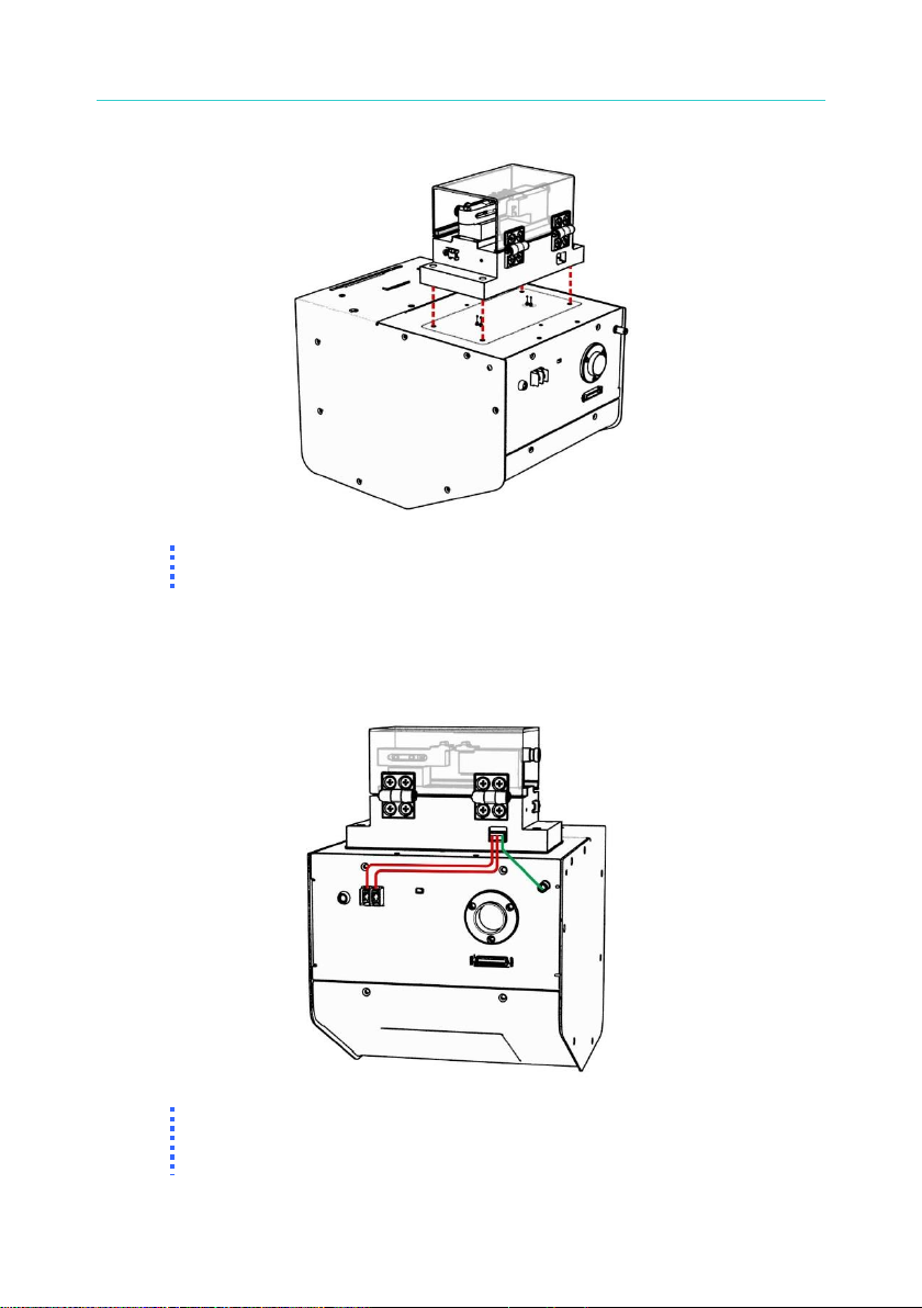
3.2 Installation
To install the EMI shielding can on the high voltage module of 19501
series partial discharge tester, use the shielding can fixed screws (M4*8
umbrella head) came along with the fixture to secure it as the figure
shown below.
Page 12

19501 Series Fixture B195000/B195001/B195002 Quick Start Guide
4
A ground wire is required to connect the EMI shielding can and the high
voltage module of the 19501 series partial discharge tester. Please use
the ground wire and shielding can ground screw (M4*8 round head) to fix
them. The location and fixing method are shown in the figure below.
When the high voltage module of the 19501 series partial discharge tester
is installed with the EMI shielding can and B195001 or B195002 fixture,
the B195001/ B195002 fixture ground wire and interlock connecting cable
should pass through the position of circled holes in the following figure for
connection.
Page 13

19501 Series Fixture B195000/B195001/B195002 Quick Start Guide
5
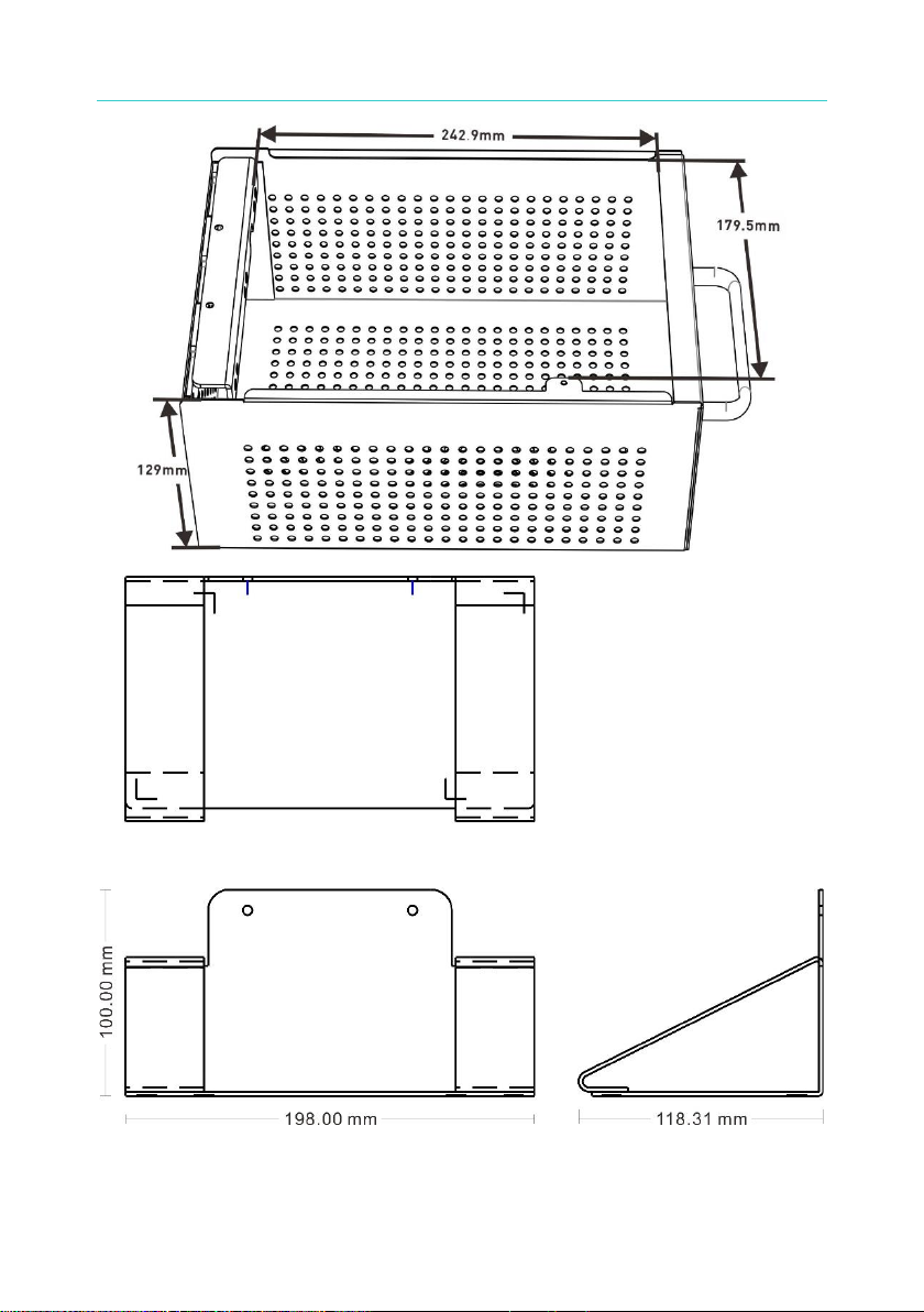
The high voltage module supporter is used to prevent the module from
vibration during testing. The supporter has magnets for fixation. Follow the
arrows shown in the figure below to fix the supporter.
Note
When the high voltage module of the partial discharge tester is
installed with an EMI shielding can and set the INTERLOCK-2 to
ENABLE, besides short-circuiting the two terminals of INTERLOCK-1
during high voltage output, the INTERLOCK-2 switch must be pressed
Page 14

19501 Series Fixture B195000/B195001/B195002 Quick Start Guide
6
at the same time to output high voltage. The INTERLOCK-2 pressing
signal will not be detected when set to DISABLE.
Page 15

19501 Series Fixture B195000/B195001/B195002 Quick Start Guide
7
3.3 Outline and Dimension
Page 16
19501 Series Fixture B195000/B195001/B195002 Quick Start Guide
8
Page 17

19501 Series Fixture B195000/B195001/B195002 Quick Start Guide
9
4. Using B195001 HV Connection Adapter
4.1 Standard Item and Accessory
Standard Item
B195001 HV Connection Adapter
Standard Accessory (Cable & Screw)
HV terminal
test cable
(Alligator clip)
L:50cm
1pcs
HV terminal
test cable
(Bare wire)
L:50cm
2pcs
Low terminal
test cable
(Alligator clip)
L:50cm
1pcs
Low terminal
test cable
(Bare wire)
L:50cm
2pcs
Green and
yellow twisted
ground wire
L:100mm
1pcs
Fixed screw
M3*20
4pcs
Note
Please specify the name when an additional item is required.
Page 18

19501 Series Fixture B195000/B195001/B195002 Quick Start Guide
10
4.2 Adapter Function and Installation
The functions of the B195001 front terminals are shown in the figure
below.
1 2 3 4
(1) RTN/Low
:
This terminal connects to the RTN/LOW
terminal on the high voltage module of the
19501 partial discharge tester, which is a low
potential terminal. This terminal is almost
equal to the ground terminal on the chassis.
(2) Low Contact
:
This terminal connects to the HVCC-RTN
terminal on the high voltage module of the
19501 partial discharge tester.
(3) HV Contact
:
This terminal connects to the HVCC-HV
terminal on the high voltage module of the
19501 partial discharge tester.
(4) HV
:
This terminal connects to the HV terminal on
the high voltage module of the 19501 partial
discharge tester. Do not touch during testing
and when the DANGER light is on.
Page 19

19501 Series Fixture B195000/B195001/B195002 Quick Start Guide
11
The functions of the B195001 rear terminals are shown in the figure
below.
(1) Interlock
:
This terminal is reserved for B195002 fixture,
and it is invalid to use it on the B195001.
(2) GND
:
Please use the enclosed ground wire to
connect the GND terminal on the high voltage
module of the 19501 partial discharge tester.
The installation of B195001 adapter is shown in the figure below:
Use the enclosed M3*20 screws to secure the B195001 adapter on the
high voltage module of the 19501 series partial discharge tester. The
direction and holes position are shown in the figure below.
Note
When securing a fixed screw, please note that the screw torque range
is 4.5~5.5kg.
Page 20

19501 Series Fixture B195000/B195001/B195002 Quick Start Guide
12
Use the enclosed wire to connect the B195001 rear terminal to the GND
terminal on the high voltage module of the 19501as the figure shown
below.
4.3 Outline and Dimension
Page 21

19501 Series Fixture B195000/B195001/B195002 Quick Start Guide
13
5. Using B195002 DIP Test Fixture
5.1 Standard Item and Accessory
Standard Item
B195002 DIP Test Fixture
Standard Accessory (Wire & Screw)
Interlock &
ground wire
L:220mm
1pcs
Fixed screw
M3*20
4pcs
Note
Please specify the name when an additional item is required.
Page 22

19501 Series Fixture B195000/B195001/B195002 Quick Start Guide
14
5.2 Fixture Function and Installation
The functions of the B195002 front terminals are shown in the figure
below.
(1) RTN/Low
:
This terminal connects to the RTN/LOW
terminal on the high voltage module of the
19501 partial discharge tester, which is a low
potential terminal. This terminal is almost
equal to the ground terminal on the chassis.
(2) Low Contact
:
This terminal connects to the HVCC-RTN
terminal on the high voltage module of the
19501 partial discharge tester.
(3) HV Contact
:
This terminal connects to the HVCC-HV
terminal on the high voltage module of the
19501 partial discharge tester.
(4) HV
:
This terminal connects to the HV terminal on
the high voltage module of the 19501 partial
discharge tester. Do not touch during testing
and when the DANGER light is on.
(5) Micro switch
:
This switch connects to the Interlock terminal
on the fixture rear side. When the acrylic
Page 23

19501 Series Fixture B195000/B195001/B195002 Quick Start Guide
15
cover is closed, the Interlock terminal will be
short-circuited.
The functions of the B195002 rear terminals are shown in the figure
below.
(1) Interlock
:
Please use the enclosed wire to connect to
the Interlock terminal on the high-voltage
module of the 19501 partial discharge tester.
The test starts only when the acrylic cover is
closed making the micro switch short-circuit.
(2) GND
:
Please use the enclosed ground wire to
connect the GND terminal on the high voltage
module of the 19501 partial discharge tester.
The installation of B195002 DIP test fixture on the 19501 partial discharge
tester is shown in the figure below:
Use the enclosed M3*20mm screws to secure the B195002 test fixture on
the high voltage module of the 19501 partial discharge tester. The
direction and holes position are shown in the figure below.
Page 24
19501 Series Fixture B195000/B195001/B195002 Quick Start Guide
16
Note
When securing a fixed screw, please note that the screw torque range
is 4.5~5.5kg.
Use the enclosed wire to connect the B195002 rear terminal to the GND
and Interlock terminal on the high voltage module of the 19501 partial
discharge tester as the figure shown below.
Note
When connecting the B195002 fixture wire to the Interlock terminal on
the high-voltage module, be sure to remove the short circuit pin on the
Interlock terminal of the original high voltage module first.
Page 25

19501 Series Fixture B195000/B195001/B195002 Quick Start Guide
17
5.3 Operation
The operation and use of B195002 fixture is described as follows:
A. The 4 screws marked in the figure below can move up and down.
If HVCC (high voltage contact check) is not required, adjust the
screws to combine the upper and lower copper blocks.
If HVCC (high voltage contact check) is required, adjust the screws
separate the upper and lower copper blocks.
Page 26

19501 Series Fixture B195000/B195001/B195002 Quick Start Guide
18
B. Loosen the marked two knobs to move the fixture slider to the right
and then fix it. Adjust the distance that is suitable for fixing the DUT.
Page 27

19501 Series Fixture B195000/B195001/B195002 Quick Start Guide
19
C. Pull the left slider on the fixture to put the DUT in and make sure that
the DUT is in good contact with the fixture.
D. Close the acrylic cover and make sure that the micro switch of
Interlock is short-circuited to start the test.
Page 28

19501 Series Fixture B195000/B195001/B195002 Quick Start Guide
20
5.4 Outline and Dimension
Page 29

19501 Series Fixture B195000/B195001/B195002 Quick Start Guide
21
Page 30

CHROMA ATE INC.
info@chromaate.com
www.chromaate.com
Copyright by CHROMA ATE INC. All Rights Reserved.
All other trade names referenced are the properties of their respective companies.
 Loading...