

Page 1

Page 2

Page 3
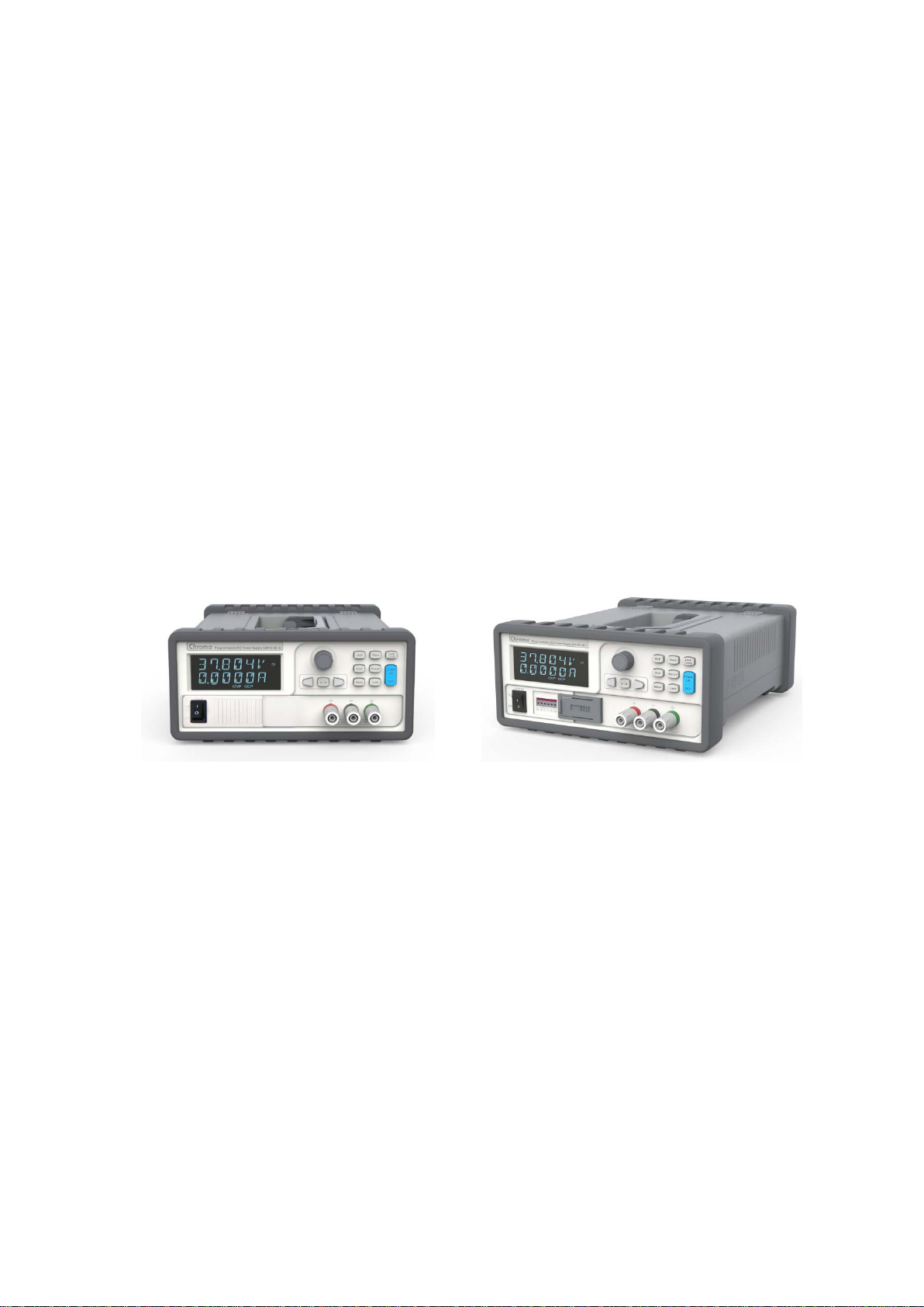
Programmable DC Power Supply
62000L Series
User’s Manual
Version 1.0
March 2017
Page 4

Legal Notices
The information in this document is subject to change without notice.
Chroma ATE INC. makes no warranty of any kind with regard to this manual, including, but
not limited to, the implied warranties of merchantability and fitness for a particular purpose.
Chroma ATE INC. shall not be held liable for errors con tained herein or dir ect, indirect, special,
incidental or consequential damages in connection with the furnishing, performance, or use of
this material.
CHROMA ATE INC.
66 Huaya 1st Road, Guishan, Taoyuan 33383, Taiwan
Copyright Notices. Copyright 2017 Chroma ATE INC., all rights reserved. Reproduction,
adaptation, or translation of this document without prior written permission is prohibited,
except as allowed under the copyright laws.
ii
Page 5

Warranty
All of Chroma’s instruments are warranted against defects in material and workmanship for a
period of one year from date of shipment. Chroma agrees to repair or replace any assembly
or component found to be defective, under normal use during this period. Chroma’s obligation
under this warranty is limited solely to repairing any such instrument, which in Chroma’s sole
opinion proves to be defective within the scope of the warranty when returned to the factory or
to an authorized service center. Purchaser is responsible for the shipping and cost of the
service item to Chroma factory or service center. Shipment should not be made without prior
authorization by Chroma.
This warranty does not apply to any p roduc ts rep aired o r al tered by persons not authorized by
Chroma, or not in accordance with instructions furnished by Chroma. If the instrument is
defective as a result of misuse, improper repair, or abnormal conditions or operations, repairs
will be billed at cost.
Chroma assumes no responsibility for its product being used in a hazardous or dangerous
manner either alone or in conjunction with other equipment. High voltage used in some
instruments may be dangerous if misused. Special disclaimers apply to these instruments.
Chroma assumes no liability for secondary charges or consequential damages and in any
event, Chroma’s liability for breach of warranty under any contract or otherwise, shall not
exceed the purchase price of the specific instrument shipped and against which a claim is
made.
Any recommendations made by Chroma regarding the use of its products are based upon
tests believed to be reliable; Chroma makes no warranty of the results to be obtained. This
warranty is in lieu of all other warranties, expressed or implied, and no representative or
person is authorized to represent or assume for Chroma any liability in connection with the
sale of our products other than set forth herein.
CHROMA ATE INC.
66 Huaya 1st Road, Guishan,
Taoyuan 33383, Taiwan
Tel: 886-3-327-9999
Fax: 886-3-327-2886
e-mail: [email protected]
http://www.chromaate.com
iii
Page 6
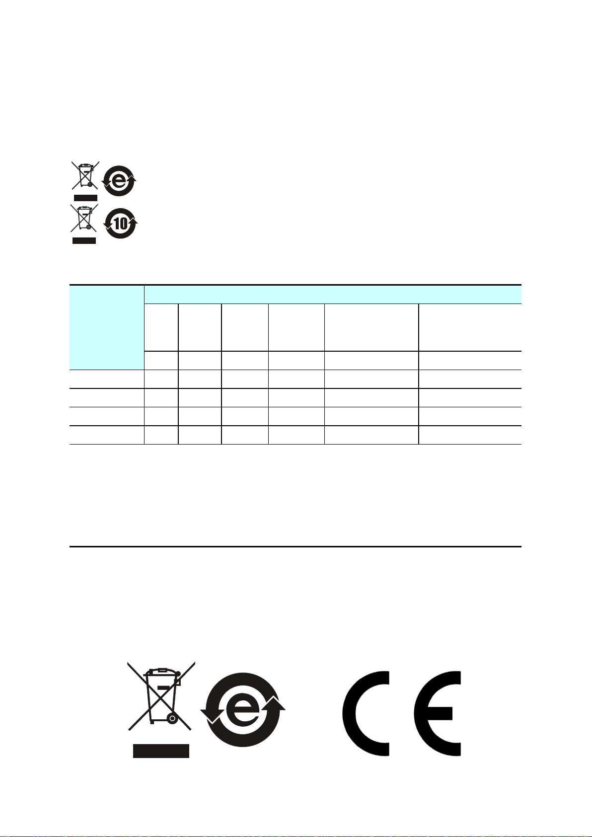
Material Contents Declaration
Hazardous Substances
Lead
Mercury
Cadmium
Hexavalent
Polybrominated
Polybromodiphenyl
Ethers
Selected Phthalates
Pb
Hg
Cd
Cr6+
PBB/PBDE
DEHP/BBP/DBP/DIBP
“O” indicates that the level of the specified chemical substance is less than the threshold level
specified in the standards of SJ/T
“
specified in the standards of SJ/T
Remarks:
Directive 2011/65/EU.
The recycling label shown on the product indicates the Hazardous Substances contained in
the product as the table listed below.
: See <Table 1>.
: See <Table 2>.
<Table 1>
Part Name
PCBA
CHASSIS
ACCESSORY
PACKAGE
Chromium
O O O O O O
O O O O O O
O O O O O O
O O O O O O
Biphenyls/
Group
-11363-2006 and EU Directive 2011/65/EU.
” indicates that the level of the specified chemical substance exceeds the threshold level
-11363-2006 and EU Directive 2011/65/EU.
The CE marking on product is a declaration of product compliance with EU
Disposal
Do not dispose of electrical appliances as unsorted municipal waste, use separate collection
facilities. Contact your local government for information regarding the collection systems
available. If electrical appliances are disposed of in landfills or dumps, hazardous substances
can leak into the groundwater and get into the food chain, damaging your health and
well-being . W hen replacing old appliances with new one, the retailer is legally obligated to
take back your old appliances for disposal at least for free of charge.
iv
Page 7
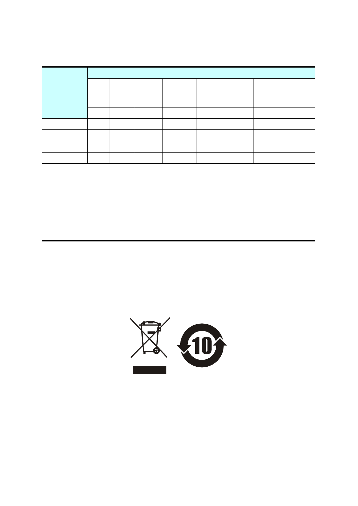
<Table 2>
Hazardous Substances
Lead
Mercury
Cadmium
Hexavalent
Polybrominated
Polybromodiphenyl
Ethers
Selected Phthalates
Pb
Hg
Cd
Cr6+
PBB/PBDE
DEHP/BBP/DBP/DIBP
“O” indicates that the level of the specified chemical substance is less than the threshold level
specified in the standards of SJ/T
“
specified in the standards of SJ/T
1.
2.
environment specified in each product’s specification.
Part Name
PCBA
CHASSIS
ACCESSORY
PACKAGE
Chromium
O O O O O
O O O O O
O O O O O
O O O O O O
Biphenyls/
Group
-11363-2006 and EU Directive 2011/65/EU.
” indicates that the level of the specified chemical substance exceeds the threshold level
-11363-2006 and EU Directive 2011/65/EU.
Chroma is not fully transitioned to lead-free solder assembly at this moment; however,
most of the components used are RoHS compliant.
The environment-friendly usage period of the product is assumed under the operating
Disposal
Do not dispose of electrical appliances as unsorted municipal waste, use separate collection
facilities. Contact your local government for information regarding the collection systems
available. If electrical appliances are disposed of in landfills or dumps, hazardous substances
can leak into the groundwater and get into the food chain, damaging your health and
well-being . W hen replacing old appliances with new one, the retailer is legally obligated to
take back your old appliances for disposal at least for free of charge.
v
Page 8
vi
Page 9
Safety Summary
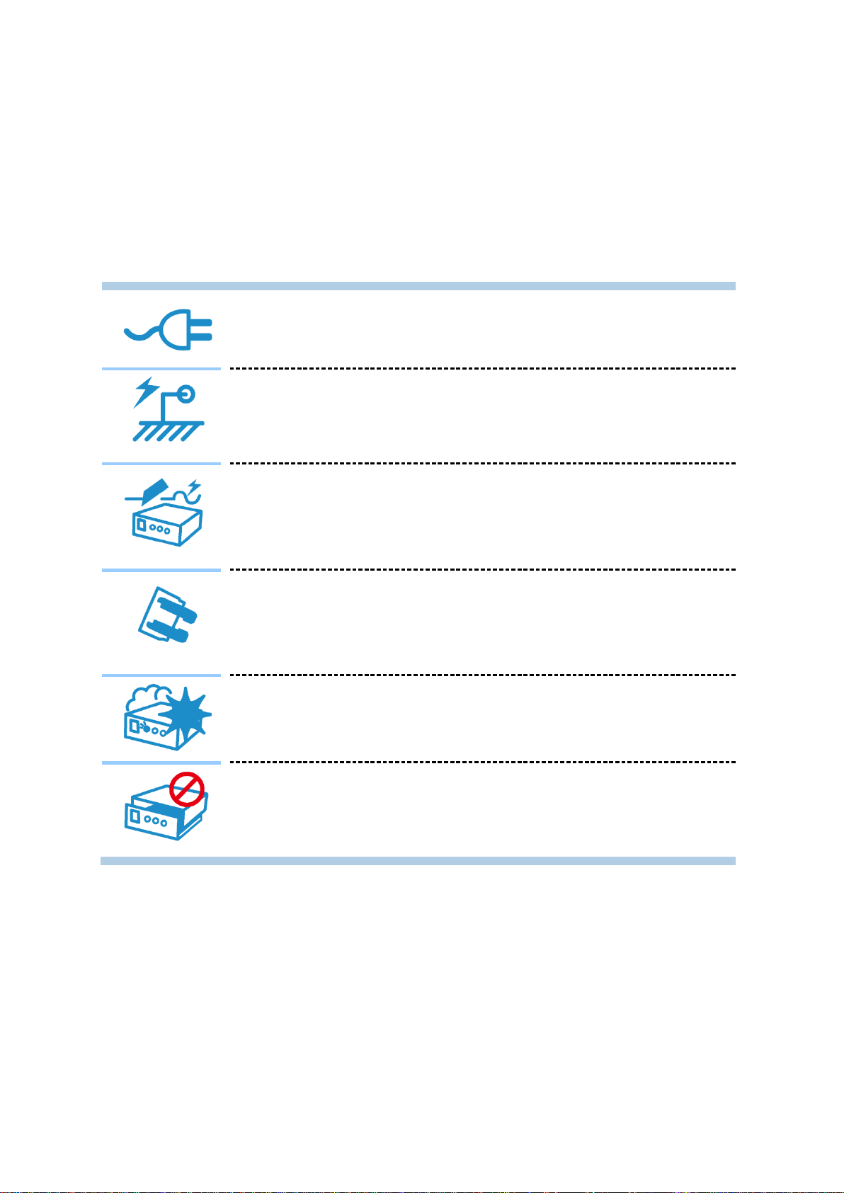
BEFORE APPLYING POWER
PROTECTIVE GROUNDING
NECESSITY OF PROTECTIVE GROUNDING
FUSES
DO NOT OPERATE IN AN EXPLOSIVE ATMOSPHERE
DO NOT REMOVE THE COVER OF THE INSTRUMENT
The following general safety precautions must be observed during all phases of operation,
service, and repair of this instrument. Failure to comply with these precautions or specific
WARNINGS given elsewhere in this manual will violate safety standards of design,
manufacture, and intended use of the instrument. Chroma assumes no liability for the
customer’s failure to comply with these requirements.
Verify that the power is set to match the rated inp ut of this pow er supply .
Make sure to connect the protective grounding to prevent an electric
shock before turning on the power.
Never cut off the internal or external protective grounding wire, or
disconnect the wiring of protective grounding terminal. Doing so will
cause a potential shock hazard that may bring injury to a person.
Only fuses with the required rated current, voltage, and specified type
(normal blow, time delay, etc.) should be used. Do not use repaired
fuses or short-circuited fuse holders. To do so could cause a shock or
fire hazard.
Do not operate the instrument in the presence of flammable gases or
fumes. The instrument should be used in an environment of good
ventilation.
Operating personnel must not remove the cover of the instrument.
Component replacement and internal adjustment can be done only by
qualified service personnel.
vii
Page 10
Safety Symbols
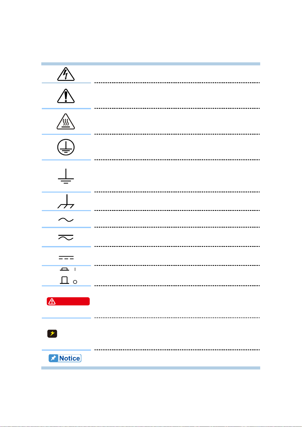
. Do not touch it to avoid any personal
The Notice sign highlights an essential operating or maintenance
procedure, condition, or statement.
WARNING
CAUTION
DANGER – High voltage.
Explanation: To avoid injury, death of personnel, or damage to
the instrument, the operator must refer to the explanation in the
instruction manual.
High temperature: This symbol indicates the temperature is
hazardous to human beings
injury.
Protective grounding terminal: This symbol indicates that the
terminal must be connected to ground before operation of the
equipment to protect against electrical shock in case of a fault.
Functional grounding: To identify an earth (ground) terminal in
cases where the protective ground is not explicitly stated. This
symbol indicates the power connector does not provide
grounding.
Frame or chassis: To identify a frame or chassis terminal.
Alternating Current (AC)
Direct Current (DC) / Alternating Current (AC)
Direct Current (DC)
Push-on/Push-off power switch
The WARNING sign highlights an essential operating or
maintenance procedure, practice, condition, statement, etc.,
which if not strictly observed, could result in injury to, or death of,
personnel or long term health hazards.
The CAUTION sign highlights an essential operating or
maintenance procedure, practice, condition, statement, etc.,
which if not strictly observed, could result in damage to, or
destruction of, equipment.
viii
Page 11

Revision History
Date
Version
Revised Sections
Mar. 2017
1.0
Complete this manual.
The following lists the additions, deletions and modifications in this manual at each revision.
ix
Page 12

Page 13

Programmable DC Power Supply 62000L Series User’s Manual
Table of Contents
1. General Information................................................................................................. 1-1
1.1 Features & Operations .......................................................................................... 1-1
1.2 Precautions........................................................................................................... 1-5
1.3 Maintaining the 62000L Series ............................................................................. 1-5
1.4 Product Users ....................................................................................................... 1-5
1.5 Safety Information................................................................................................. 1-6
1.6 Symbols and Terms .............................................................................................. 1-7
1.7 Electrical Specifications ........................................................................................ 1-8
1.8 Contents ............................................................................................................... 1-9
1.9 Dimension ............................................................................................................ 1-9
2. Preliminary Check ................................................................................................... 2-1
2.1 Power-On Check .................................................................................................. 2-1
2.2 Output Check ........................................................................................................ 2-1
2.2.1 Voltage Output Check ................................................................................. 2-1
2.2.2 Current Output Check ................................................................................. 2-2
2.3 Input Power Check ............................................................................................... 2-2
2.3.1 Power-Line Cord Check .............................................................................. 2-2
2.3.2 Power-Line Voltage Selection ..................................................................... 2-2
2.4 Panel Check & Setting .......................................................................................... 2-3
2.4.1 Front Panel Overview .................................................................................. 2-3
2.4.2 Rear Panel Overview .................................................................................. 2-4
2.4.3 Voltage & Current Limit Settings .................................................................. 2-5
2.4.4 Display Check ............................................................................................. 2-6
3. Power Supply Operation ......................................................................................... 3-1
3.1 Constant Voltage Operation .................................................................................. 3-2
3.2 Constant Current Operation .................................................................................. 3-3
3.3 Storing and Recalling Operation States ................................................................ 3-4
3.4 Setting the Overvoltage Protection ....................................................................... 3-5
3.5 Setting the Overcurrent Protection ........................................................................ 3-6
3.6 Remote Sensing (for 62010L-36-7 only) ............................................................... 3-7
3.6.1 Constant Voltage Regulation ....................................................................... 3-8
3.6.2 Output Rating .............................................................................................. 3-9
3.6.3 Output Interference ..................................................................................... 3-9
3.6.4 Stability ....................................................................................................... 3-9
3.6.5 Remote Sensing Connections ..................................................................... 3-9
3.7 Master & Slave Application (62010L-36-7 Only) ................................................. 3-10
3.7.1 Connections in Series ............................................................................... 3-11
3.7.2 Connections in Parallel .............................................................................. 3-13
3.7.3 Other Settings for Multiple Connections .................................................... 3-15
3.8 Turning Off the Output ........................................................................................ 3-17
3.9 SEQ (Sequencing Mode) .................................................................................... 3-17
3.10 System Operations ........................................................................................... 3-22
3.10.1 Err or States ............................................................................................... 3-22
3.10.2 Beep/Alarm Settings .................................................................................. 3-22
3.10.3 Display Control .......................................................................................... 3-23
3.10.4 OCP De lay ( OCPDEL) Settings................................................................. 3-24
3.10.5 Vrange ...................................................................................................... 3-24
3.10.6 Style .......................................................................................................... 3-24
3.10.7 Identification .............................................................................................. 3-25
3.10.8 SCPI Command Version ........................................................................... 3-25
xi
Page 14

Programmable DC Power Supply 62000L Series User’s Manual
Calibration ......................................................................................................... 3-25
3.11
3.11.1 Un-secure Calibration ................................................................................ 3-26
3.11.2 Securing Calibration .................................................................................. 3-26
3.11.3 Changing the Security Code ...................................................................... 3-27
3.11.4 Calibration Procedures .............................................................................. 3-27
3.11.5 Calibration String ....................................................................................... 3-29
3.12 Remote Control Settings ................................................................................... 3-30
3.12.1 Remote Interface Selection ....................................................................... 3-30
3.12.1.1 USB Interface .................................................................................................. 3-30
3.12.1.2 GPIB Interface ................................................................................................. 3-30
4. Remote Control Reference ...................................................................................... 4-1
4.1 SCPI La nguage Summary .................................................................................... 4-1
4.1.1 SCPI Language Introduction ....................................................................... 4-1
4.1.2 Symbols Used in SCPI Commands ............................................................. 4-1
4.1.3 Command Format in This Manual ............................................................... 4-2
4.1.4 MIN and MAX Parameters ........................................................................... 4-2
4.1.5 Setting and Querying Commands ................................................................ 4-2
4.1.6 SCPI Command Terminators ...................................................................... 4-3
4.1.7 Common SCPI Commands ......................................................................... 4-3
4.1.8 SCPI Parameter Types ............................................................................... 4-3
4.2 SCPI Commands .................................................................................................. 4-4
4.2.1 Output Settings and Operation Commands ................................................. 4-4
4.2.2 Triggering Commands ................................................................................. 4-8
4.2.2.1 Trigger Source Options ...................................................................................... 4-8
4.2.2.2 Triggering Command Description ...................................................................... 4-9
4.2.3 Output Control Commands .......................................................................... 4-9
4.2.3.1 Commands for Master & Slave Application ..................................................... 4-10
4.2.3.2 Commands for Output Sequence .................................................................... 4-10
4.2.4 System-Related Commands ...................................................................... 4-12
4.2.5 Calibration Commands .............................................................................. 4-14
4.2.6 Status Reporting Commands .................................................................... 4-15
4.2.7 IEEE-488 Conformance Information .......................................................... 4-17
4.3 Programming Overview ...................................................................................... 4-17
4.3.1 Regarding Programming Ranges .............................................................. 4-17
4.3.2 Regarding SCPI Status Registers ............................................................. 4-18
4.3.2.1 The Questionable Status Register ................................................................... 4-20
4.3.2.2 The Standard Event Register .......................................................................... 4-20
4.3.2.3 The Status Byte Register ................................................................................. 4-21
5. Error Messages ........................................................................................................ 5-1
5.1 Execution Errors ................................................................................................... 5-1
5.2 Self-Test Errors .................................................................................................... 5-4
5.3 Calibration Errors .................................................................................................. 5-4
xii
Page 15

General Information
1. General Information
This section contains general information about 62000L series Programmable DC Power
Supply. The information is shown below:
1. Features & Operations Overview
2. Warranty Information
3. Safety Information
4. Symbols and Terms
5. Specifications
6. Inspection
7. Options and Accessories
If you have any questions after reading this information, please contact your local service
representative.
1.1 Features & Operations
The 62000L series is a high performance auto-ranging portable DC power supply (Max.:
108W, 36V, 7A / 150W, 60V, 6A) with a single channel output, and standard GPIB and USB
interfaces. The outstanding features and easy operation provide a great solution for your R&D,
manufacturing test, and QC inspection requirements.
Key Features:
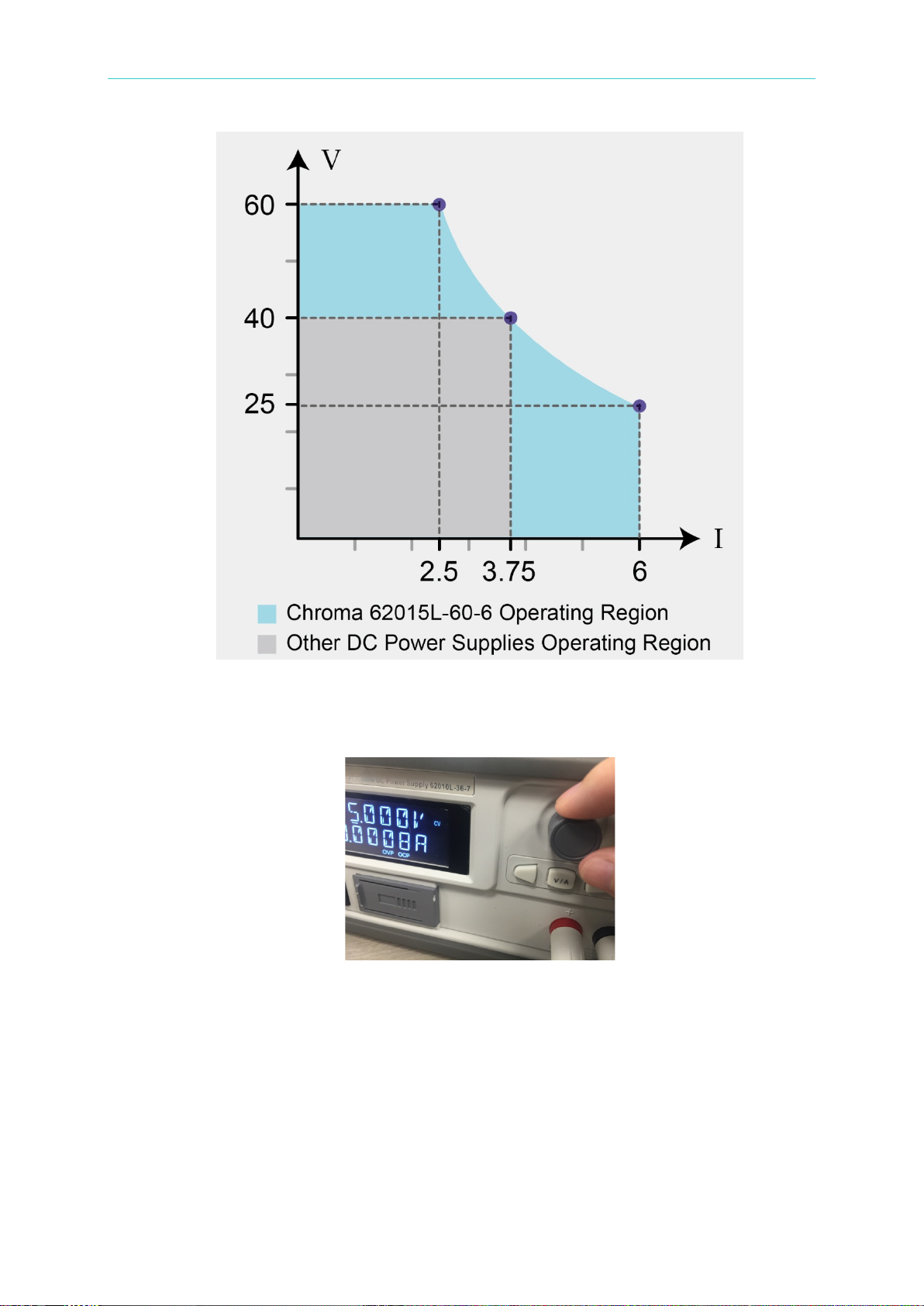
Auto-ranging allows you to freely adjust voltage and current
This feature eliminates the need to manually select the optimum range allowing all of the
power to be available across all of the voltage and current settings as shown below.
1-1
Page 16
Programmable DC Power Supply 62000L Series User’s Manual
Easy-To-Use Control Knob
The knob on the 62000L series utilizes photo-interrupted technology. It’s durable and
reliable. The enhanced sensitivity completely replaces the need for numerical input keys.
Highly Readable Display
High Accuracy and Resolution
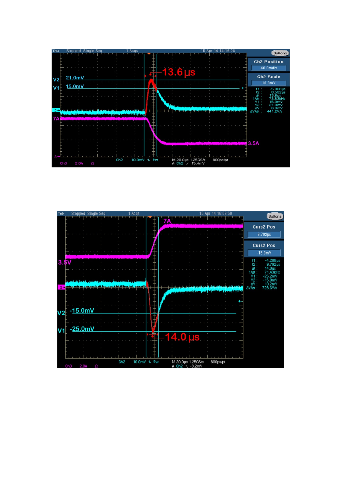
Fast Response Time (TR: 62010L-36-7<30us / 62015L-60-6<50us)
The oscilloscope test below measures the time for the output voltage to recover to within
15 mV of nominal output voltage. The overshoot change is a result of a 7 A to 3.5 A load
step, with the recovery taking only 13.6 us.
1-2
Page 17
General Information
Wave in Blue: Voltage / Wave in Purple: Current
Fast Response Time – 1
This oscilloscope test measures the time for the output voltage to recover to within 15
mV of nominal output voltage. The undershoot change is a result of a 3.5 A to 7 A load
step, with the recovery taking only 14.0 us.
Wave in Blue: Voltage / Wave in Purple: Current
Fast Response Time – 2
Remote Voltage Sense without Shorting Bars (for 62010L-36-7 only)
Overvoltage Protection (OVP), Overcurrent Protection (OCP), and Over-Temperature
Protection (OTP)
Excellent Load and Line Regulation
Low Ripple and Noise (<2 mVpp/350 µVrms, 2 m A rms [20Hz~20MHz])
Sixteen Storage Locations (0 ~ 15) for User-Defined Operating States
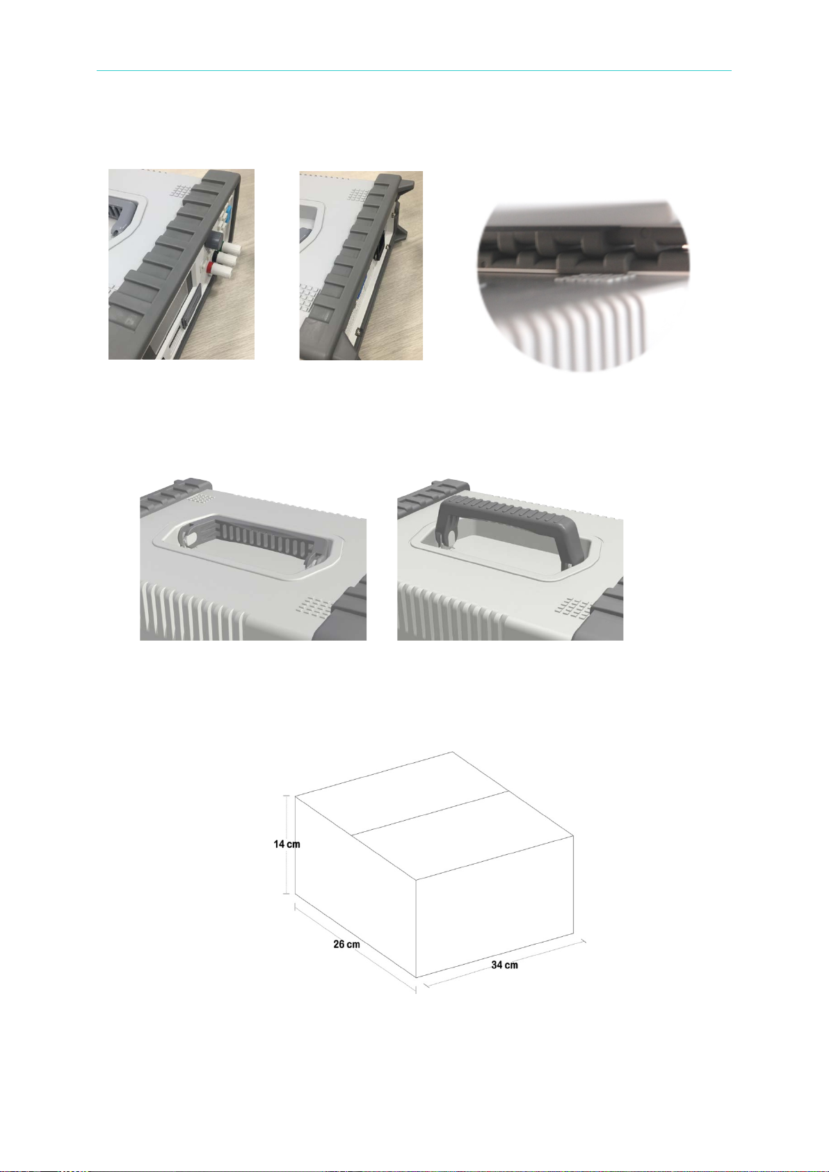
Easy-To-Stack-Up Body
1-3
Page 18
Programmable DC Power Supply 62000L Series User’s Manual
The 62000L series includes front and rear non-slip bumpers whose indentation allows
the same models to be stacked.
The Front Bumper The Rear Bumper Units Stacked
Hidden Carrying Handle
Hidden State Holding State
Portable Size (H: 2U, W: 1/2U) and Light Weight (<2.5Kgs or 5.5Lbs)
The 62000L series weight is less than 2.5Kgs. The carton size for one P961XA is
26(W)*14(H)*34(D) cm. The shipping weight for marine shipment is about 2.5 Kgs. For
air shipment the weight is about 3Kgs.
Fast Voltage Programming Speed
1-4
Page 19

General Information
The performance accuracy is subject to calibration accuracy.
Flexible Features:
Standard USB / GPIB (IEEE-488) Interfaces
SCPI Commands Compatible with the Keysight E3632A
Easy I/O Setup through the Front Panel
Easy Way to Complete Calibration
Powerful Voltage Integration Solution via Master-Slave Connection Up to 7 Devices (Max.
252V for 62010L-36-7 only)
Powerful Current Integration Solution via Master-Slave Connection Up to 7 Devices (M ax.
49A for 62010L-36-7 only)
Compensative External Sense when Conducting Master-Slave Connection (for
62010L-36-7 only)
Operational Features:
Autoranging from 1mV to 36V / 1mV to 60V and from 1mA to 7A / 1mA to 6A
Constant Voltage (CV) or Constant Current (CC) Operation
Selective OVP and OCP Settings
Short Circuit Protection
Sixteen Storage Locations
External Sense for Load Voltage (for 62010L-36-7 only)
Error Message Tips
Calibration via the Front Panel or Remote Interfaces
High Efficiency with A Durable Control Knob
1.2 Precautions
Please carefully read the manual before operating this device.
This manual is for reference only. Please consult your distributor for further assistance.
The contents of this manual may be amended by the manufacturer without notice.
Never dismantle the equipment or the equipment may be damaged.
This equipment must not be used in dangerous situations where damage m ay result.
This product should be placed in a safe area while not in use. The maximum weight
loading on the 62000L series case is 20Kgs. Ex ceeding this might cause the equipment to
malfunction.
1.3 Maintaining t he 62000L Series
To clean the instrument, use a damp cloth or mild, water-based cleaner. Only clean the
exterior of the instrument. Do not apply cleaner directly to the instrument or allow liquids to
enter or spill on the instrument.
1.4 Product Users
This product is intended for use by qualified personnel who are cognizant of shock hazards
and familiar with the safety precautions required to avoid possible injury. Read and follow all
1-5
Page 20

Programmable DC Power Supply 62000L Series User’s Manual
Please read through the following safety information before using the
product.
CAUTION
installation, operation, and maintenance information carefully before using the product. Refer
to the documentation contained in this guide for complete product specifications.
If the product is used in a manner not specified, the protection provided by t he pr oduct
warranty may be voided.
The types of product users are:
Responsible person is the individual or group responsible for the use and maintenance of
equipment, for ensuring that the equipment is operated within its specifications and operating
limits, and for ensuring that operators are adequately trained.
Operators use the product for its intended function. They must be trained in electrical safety
procedures and proper use of the instrument. They must be protected from electric shock and
contact with hazardous live circuits.
Maintenance personnel perform routine procedures on the product to keep it operating
property, for example, setting the line voltage or replacing consumable materials.
Maintenance procedures are described in the user documentation. The procedures explicitly
state if the operator may perform them. Otherwise, they should be performed only by service
personnel.
Service personnel are trained to work on live circuits, perform safe installations, and repair
products. Only properly trained service personnel may perform installation and service
procedures.
1.5 Safety Information
Measurement Category II is for measurements performed on circuits which are directly
connected to the low voltage installation.
To avoid possible electric shock or personal injury, please read and follow these guidelines
carefully:
Follow the guidelines in this manual and DO NOT use t he power supply if the case is
damaged. Check the case and terminals. Then contact your distributor for the case
replacement.
When using the probes, always keep your fingers behind the finger guards.
Always connect the common test leads (black) before connecting the live test leads (red),
and disconnect the live test leads (red) before disconnecting the common test leads
(black). This will reduce the chance of an electric shock.
If you need to open the power supply’s case or replace any parts, read the instructions in
this manual first. You must be qualified to perform this action.
When replacing fuses, use only the same type and same rating as specified.
Do not try to operate the power supply if it is damaged. Disconnect the power from the
equipment and consult the local service representative. Return the product to Chroma
service department if necessary.
Make sure your power cord corresponds to requirements of local regulations. When
replacing it, the specification must be the same as the previous one. An incorr ect power
cord may cause unpredictable harm or damage. Some rules to follow are shown below.
1-6
Page 21
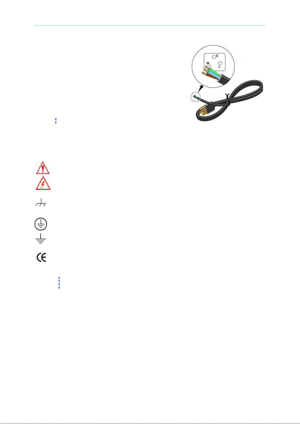
A. Use the power cord that is shipped with your product.
Note
This appliance must be connected to earth ground.
Note
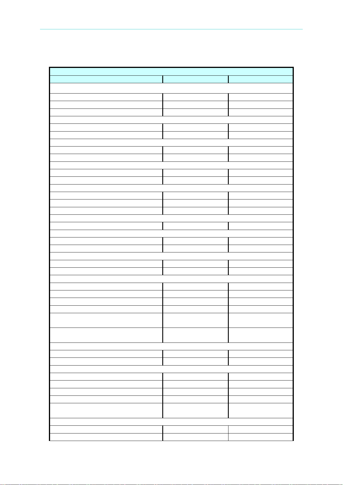
The complete s et of 62000L series specifications is included in specification
table.
B. Ground the product. The 62000L series is grounded
through the grounding conductor of the power cord.
To avoid electric shock, only use an approved power
cord with the product, and verify that it’s connected to
earth ground.
C. Position the unit on a firm, stable surface.
D. Shown belo w are the cord’s connections.
Green: Earth (E)
Blue: Neutral (N)
Brown: Live (L) - Phase
1.6 Symbols and Ter m s
This symbol indicates hazards that may cause damage to the i nstru ment o r ev en result
in personal injury.
General Information
T his symbol indicates high voltage may be present. Use extra caution before taking
any action.
This symbol indicates the frame or chassis terminal needs to be connected to actual
earth ground.
This symbol indicates a “Protective Conductor Terminal.”
This symbol indicates an earth (ground) terminal.
This symbol indicates this product complies with the essential requirements or the
applicable European laws or directives with respect to safety, health, environment, and
consumer protections.
1-7
Page 22
Programmable DC Power Supply 62000L Series User’s Manual
ELECTRICAL SPECIFICATIO NS
Model
62010L-36-7
62015L-60-6
Output Voltage
0~36V
0~60V
Output Current
0~7A
0~6A
Output Power
108W
150W
Line Regulation1
Voltage
0.01%+2mV
0.01%+2mV
Current
0.01%+250uA
0.01%+250uA
Load Regulation2
Voltage
< 0.01%+2mV
< 0.01%+2mV
Current
< 0.01%+250uA
< 0.01%+250uA
Measurement Accuracy
Voltage
0.05%+5mV
0.05%+5mV
Current
0.15%+5mA
0.15%+5mA
Output Noise & Ripple3
Voltage Noise (p-p)
< 2mVp-p
< 3mVp-p
Voltage Ripple (rms)
< 0.35mVrms
< 0.5mVrms
Current Ripple (rms)
< 2mArms
< 2mArms
Transient Response Time
100% to 50% load change
< 30usec
< 50usec
Temperature Coefficient4
Voltage
0.01%+3mV
0.01%+10mV
Current
0.02%+3mA
0.02%+3mA
Drift4
Voltage
0.02%+1mV
0.05%+10mV
Current
0.1%+1mA
0.15%+2mA
Programming & Measurement Resolution
Voltage (Front Panel)
1mV
10mV
Current (Front Panel)
0.1mA
1mA
Voltage (Remote Interface)
1mV
1mV
Current (Remote Interface)
0.1mA
0.21mA
Voltage (An alog Prog ramming
Interface)
1mV
1mV
Current (Analog Programming
Interface)
0.21mA
1mA
Programming Accuracy5
Voltage
0.05%+10mV
0.05%+10mV
Current
0.2%+10mA
0.2%+10mA
Programming Response Time6
Rise Time (Full Load)
< 40ms
< 100ms
Rise Time (No Load)
< 20ms
< 35ms
Fall Time (Full Load)
< 40ms
< 50ms
Fall Time (No Load)
< 400ms
< 500ms
Measure Volt age, Current (under
GPIB command using Measure)
OVP/OCP
OVP Accuracy
0.1%+0.2V
0.1%+0.3V
OCP Accuracy
0.2%+0.2A
0.2%+0.3A
1.7 Electrical Specifications
Output Ratings (@ 0℃ ~ 40℃)
1-8
< 20ms < 20ms
Page 23
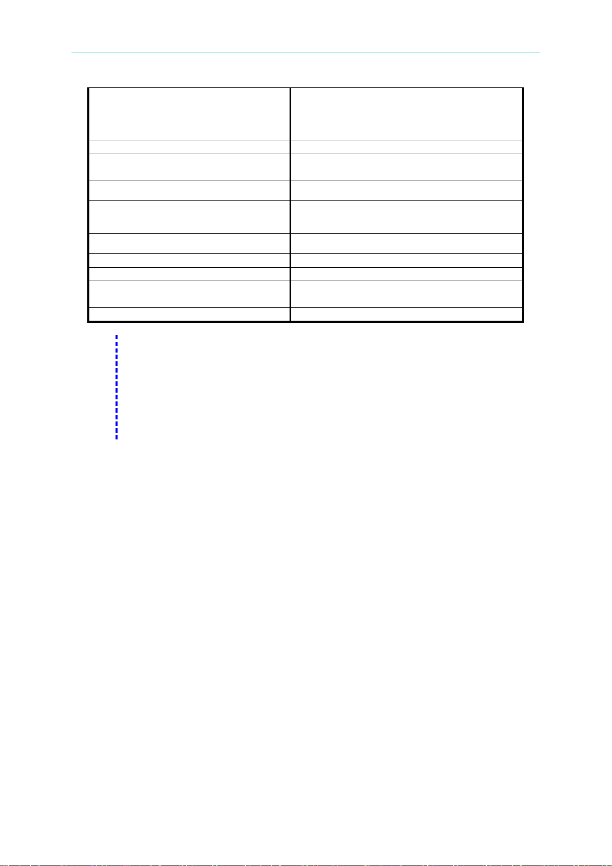
General Information
OVP Activation Time
<1.5ms (when the trip voltage is equal or
2V)
OCP Activation Time
<10ms
AC Input Operating Volt age Range
1φ 100~120Vac ± 10% V
or 1φ
220~240Vac ± 10% VLN, 47~63 Hz
Operating Humidity
Maximum relative humidity 80% for
Storage T e mperature
Operating Altitude
Up to 2000 M
Interfaces
USB & GPIB standard
Dimension (H x W x D)
88.6 x 214.6 x 280.7 mm / 3.49 x 8.45 x
11.05 inch
Weight
< 2.5 kg / 5.5 lbs
Note
1. Change in output voltage or current for any load change within ratings.
excursion (for resistive load). Excludes command processing time.
greater than 2V)
<10ms (when the trip voltage is less than
LN
Operating Temperature
2. For 0-100% load step with nominal line voltage.
3. with outputs ungrounded, or either output terminal grounded, 20 Hz t o 20 MHz.
4. Maximum change in output/read-back per °C after a 30-minute warm-up.
5. The accuracy specifications are gained under 1-hour warm-up condition and
the calibration at 25°C.
6. Maximum time required for output voltage to settle within 1% of its total
1.8 Contents
0℃ to 40℃
temperature up to 35℃
- 40℃ to 70℃
Make sure that you have received the following items in the shipment of your power supply. If
anything is missing, damaged, or malfunctioning, contact your distributor.
One 62010L-36-7 or 62015L-60-6 (88.6[H] x 214.6 [W] x 280.7 [D] mm, < 2.5 Kgs)
USB & GPIB interface card (USB cord included)
Front/rear bumper
NEMA 5–15 one power line cord
One CD (including this electronic User's Manual)
1.9 Dimension
1. The dimension without the front & rear bumpers, and the terminals is (LxWxD - 214.6 x
88.6 x 280.7 mm).
2. The dimension with the front & rear bumpers, but without the terminals is (LxWxD – 226.8
x 107 x 305 mm).
1-9
Page 24

Page 25

Preliminary Check
2. Preliminary Check
Before using this power supply for the first time, please complete the following actions.
1. Make sure that the power line voltage setting on the rear panel is correct:
The power line voltage must be set to the proper value for your country once you receive
this unit. There are 115 Vac and 230 Vac selections available.
2. Make sure that the correct power line fuse is installed: For 115 Vac, a 4 AT fuse is used.
For 230 Vac, a 2.5 AT fuse is used.
3. Make sure that the power cord is connected.
2.1 Power-On Check
When the power supply is powered on, it will execute an automatic self-test that checks the
internal microprocessor and allows the user to check the display visually.
All of the segment of the display will light up during the power-on self-test is executing.
If the power-on test failed, an error is generated and the ERR annunciat or is lit.
2.2 Output Check
An output check is performed in order to verify that the power supply outputs are valid and
properly responding to commands from the front panel.
2.2.1 Voltage Output Check
Through the following steps, you may check the basic voltage functions under no load
conditions.
1. Turn on the power supply: The power-on/reset state is running, the output is disabled (the
OFF light is on), and the knob is selected for voltage control.
2. Enable the outputs: After pressing the Output On/Off button once, some symbols, such as
OVP, OCP are lit, as well as the C V or CC according to the resistance o f the test load. The
blinking cursor can be changed by turning the knob. Please note that the display is in the
meter mode which means that the display shows the actual output voltage and current.
3. Verify that the front panel voltmeter responds to knob control within the
0~36V(62010L-36-7)/0~60V(62015L-60-6) ranges: Rotate the knob clockwise or
counter-clockwise to check whether the voltmeter tracks th e knob control, and the
ammeter shows nearly zero amps.
4. Make sure that the voltage can be adjusted within the 0~36V (62010L-36-7)/0~60V
(62015L-60-6) range: Rotate the knob until the voltmeter shows 36V/60V.
2-1
Page 26

Programmable DC Power Supply 62000L Series User’s Manual
2.2.2 Current Output Check
Through the following steps, you may check the basic current functions with a short on the
power supply’s output.
1. Turn on the power supply: The power-on/reset state is running, the output is disabled (the
OFF light is on), and the knob is selected for voltage control.
2. Connect a short across the (+) and (–) output terminals with an insulated test lead.
3. Enable the output: Some symbols, such as OVP, OCP are lit, as well as the CV or CC
according to the resistance of the test lead. The blinking cursor can be changed by turning
the knob. Please note that the display is in the meter mode which means that the display
shows the actual output voltage and current.
4. Verify that the front panel ammeter responds to knob control within the
0~7A(62010L-36-7)/0~6A(62015L-60-6) range: Rotate the knob clockwise or
counter-clockwise to check whether the ammeter tracks the knob control and shows
nearly zero.
5. Make sure that the current can be adjusted within the 0~7A/0~6A range: Rotate the knob
until the ammeter shows 7A/6A.
2.3 Input Power Check
This power supply can operate properly using a 115V or 230V single phase AC power source
at 50Hz to 60Hz. The rear panel shows the nominal input voltage set for the power supply at
the factory. If need be, the power-line voltage setting can be changed according to the
instructions as shown in “Power-Line Voltage Selection” below.
2.3.1 Power-Line Cord Check
A power-line cord, which has an appropriate plug for your location, is shipped with the power
supply. If a wrong power-line cord is included with your power supply, contact your local
distributor.
This power-line cord consists of a 3-wire grounding type power lead where the third conductor
is the ground. You should ground the power supply by plugging the power-line cord into a
proper outlet. Please do not operate this equipment without effective grounding facilities.
2.3.2 Power-Line Voltage Selection
To select the power-line voltage, you have to adjust two components, including the power-line
voltage selector and the power-line fuse. They are located on the power-line module on the
rear panel.
When you want to change the power-line voltage, please proceed as follows.
1. Remove the power cord: Use a flat-blade screwdriver to remove the fuse-holder assembly
from the rear panel.
2. Install the correct line fuse: Take out the power-line voltage selector from the power-line
module and install the correct fuse
115Vac, 4AT Fuse
2-2
Page 27
Preliminary Check
Note
The default setting is 230V, make sure that the correct voltage is applied and the
fuse works properly.
230Vac, 2.5AT Fuse
3. Change position of the power-line voltage selector until the correct voltage appears.
4. Put back the power-line voltage selector and the fuse-holder assembly.
2.4 Panel Check & Setting
The front panel overview discusses the function key description, various settings, and the
description of the display. The rear panel overview discusses the optional interfaces.
2.4.1 Front Panel Overview
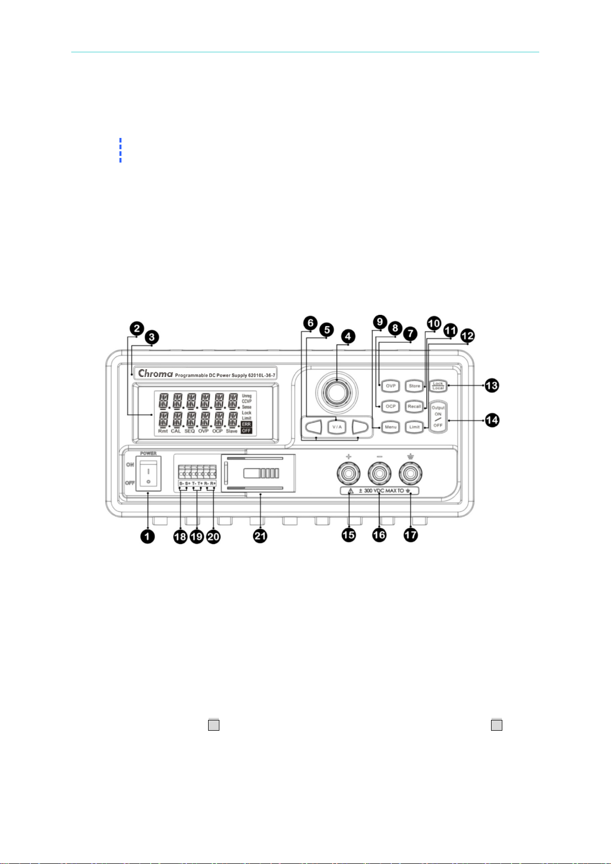
1. Power Switch: Press the (l) side to turn the power on and the (O) side to turn the power
off.
2. Display: During operation, the display shows information about the output (top row) for
voltage, and (bottom row) for current. During configuration, the display shows a control
interface.
3. Brand & Model Sticker Area: This area shows the product manufacturer and model
name.
4. Navigation Wheel: Rotate this knob to increase or decrease the flashing digit by turning
the knob clockwise or counter-clockwise. It is also used to select menu items.
5. V/A Button: Press this button to change the output from Volts to Current or Current to
Volts. Pressing this button long under the SEQ mode in output condition, the display will
show the information of V & A, V & W, or SEQCNT.
6. Arrow Buttons: Press once. The display cursor moves right one digit. Press once.
The display cursor moves left one digit. Pressing these buttons under the Store and the
Recall, you can see the set parameters.
7. OVP Button: Enable or disable the overvoltage protection function, set the trip voltage
level, and clear overvoltage condition.
2-3
Page 28
Programmable DC Power Supply 62000L Series User’s Manual
8. OCP Button: Enable or disable the overcurrent protection function, set the trip current
level, and clear overcurrent condition.
9. Menu: This button accesses the function settings. When the Menu button is pressed, and
the knob is rotated, the display will show SENSE, MA/SL, SEQ, SYSTEM, CAL, and GPIB
one by one. This button is also used to answer “Yes”, i.e. “Confirmed” or “Applied.”
10. Store Button: Store an operating state at the location 0, 1, 2… or 15.
11. Recall Button: Recall a previously stored operating state from the location 0, 1, 2… or 15.
12. Limit Button: Press it to show the voltage and cur rent limit values on the display and
allow the knob adjustment to set the limit values.
13. Lock/Local Button: When press ing the LOCK button, the Lock annunciator on the
display is lit, and the Lock function is enabled until the same button is pressed once again.
This button can be used as the Local Key when the power supply is operating under the
remote interface mode.
14. Output On/Off Button: Enable or disable the power supply output. This key toggles
between on and off.
15. Positive Terminal: Red terminal outputs positive volt age.
16. Negative Terminal: Black terminal outputs negative voltage.
17. GND Terminal: Terminal is at earth potential. Used for measurement of control circuits
designed to be operated with one terminal at earth potential.
18. Sensing Terminal (S+/S-): The Remote Sensing Terminal is used to compensate for load
current dependent voltage drops.
19. Transfer Terminal (T+/T-): Under the Master-Slave Mode, the master unit’s T+ connects
to the first slave unit’s R+. Then its R- connects to the other unit’s R+, and so on. The last
slave unit’s R- connects to the master unit’s T-.
20. Recipient Terminal (R+/R-): Under the Master-Slave Mode, the master unit’s T+
connects to the first slave unit’s R+. Then its R- connects to the other unit’s R+ and so on.
The last slave unit’s R- connects to the master unit’s T-.
21. Remote Sensing Cover: This cover is used to protect against moisture and dust.
2.4.2 Rear Panel Overview
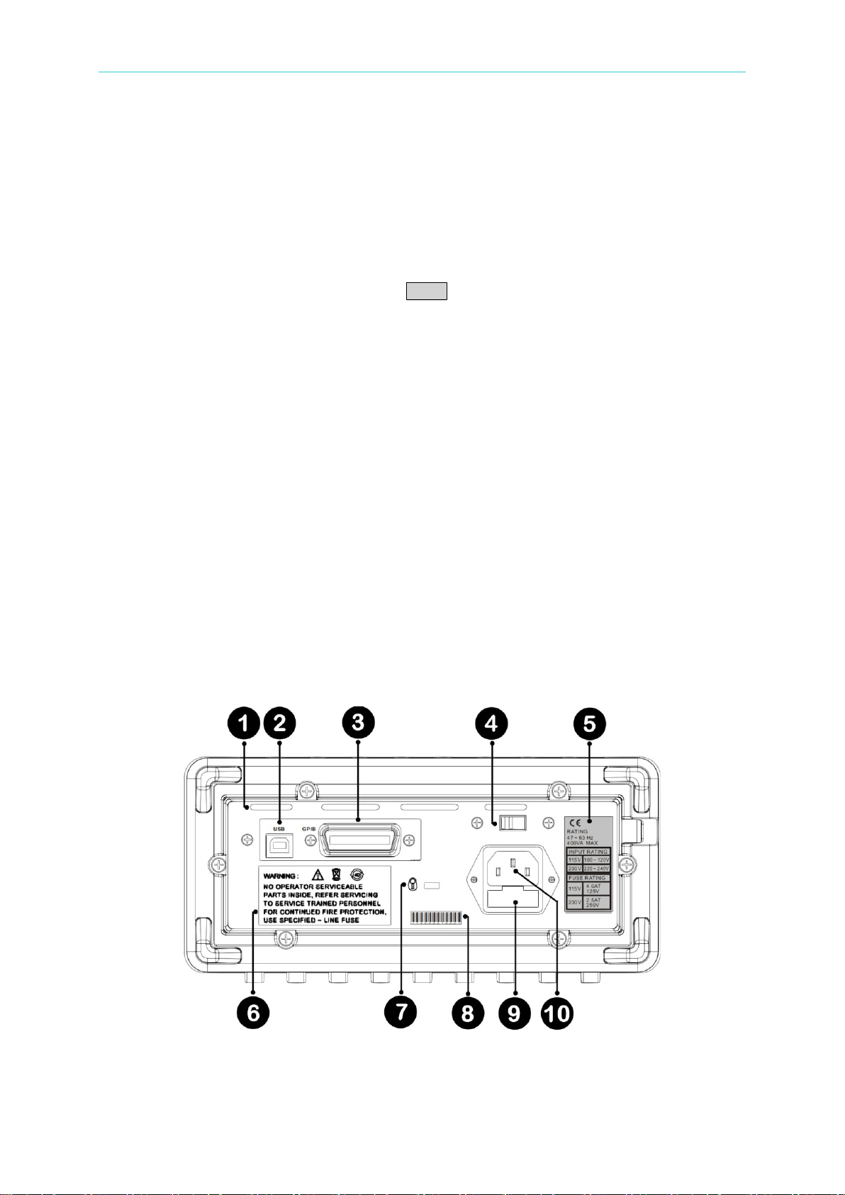
1. Air Outlet: There are four air vents for cooling purposes.
2. USB Interface: USB interface
2-4
Page 29

Preliminary Check
3. GPIB Interface: Through the IEEE-488 interface, you can communicate with any PC
which has an IEEE-488 port.
4. Power-Line Voltage Setting: There are 115V & 230V options.
5. Information: This power supply conforms to CE requirements, with a maximum of 400VA
consumption. As t he note indicates the power supply requires the correct rated power line
voltage and specified power line fuse.
6. Warning Indication: If there is something wrong with the unit, please ask trained
personnel for assistance. To maintain fire protection, use the correct specified line fuse.
7. Security Lock Port: This port is used to insert a security lock that prevents the unit from
being stolen or moved.
8. Serial Number: The number is the identification of the unit. If repairs are needed please
supply this number and the condition of the units to your local distributor or the factory via
the email address [email protected]
.
9. Fuse Holder: If the fuse is broken, please use the correctly rated one to replace it.
10. Power Line Inlet: This input is for power line voltages only. Before powering the unit on,
please check the voltage setting 115V/230V in order to make sure it meets your local
requirements.
2.4.3 Voltage & Current Limit Settings
The CV Limit refers to a required setting condition when outputting a constant voltage in need.
The CC Limit refers to a required setting condition when outputting a constant current in need.
The concept of the CV/CC limit setting is not the same as the Vrange’s at the section 3.10.5
since the limit depends on the relationships between the interactive factors of voltage setting,
resistance (RLoad), and rated/non-rated current. For example:
1. When
output constantly. The output current is in an inversed ratio with the RLoad.
2. When
output constantly. The output voltage is in a direct ratio with the RLoad, and it will stop
rising when the output voltage is equal to the setting value of the CV Limit, however, if the
RLoad increases, the power supply will turn to the CV mode to output.
Besides this, there is something you should know below.
If adjusting a CV limit under the Output ON, please make su re whether this supply is in the CV
mode since the knob rotation in the CV meter mode wil l trig the CV limit setting mode
simultaneously, and the values on the both displays are the same. In this case, if the sam e
condition exists in the CC mode, once the RLoad changes, it might burn out your DUT. So in
the CC mode, before the RLoad changes, you have to press the limit button once, and adjust
the CV limit value to protect your DUT.
If adjusting a CC limit under the Output ON, please make sure whether this supply is in the
CC mode since the knob rotation in the CC meter mode wil l t r ig the CC limit setting mode
simultaneously, and the values on the both displays are the same. In this case, if the same
condition exists in the CV mode, once the RLoad changes, it might burn out your DUT. So in
the CV mode, before the RLoad changes, you have to press the limit button once, and adjust
the CC limit value to protect your DUT.
To set the voltage and current limit values through the front panel, please follow the
procedures below.
_
_
< _, the power supply will be in the CV mode, and its voltage will
CC_Limit, the power supply will be in the CC mode, and its current will
2-5
Page 30
Programmable DC Power Supply 62000L Series User’s Manual
1. Press the Limit button to display the def ault values.
2. Move the blinking cursor to the proper position by using the or buttons, and change
the blinking cursor value to the required volt age limit by rotating the control knob. If the
limit change times out, press the Limit button again.
3. Set the knob to current control mode using the V / A button.
4. Move the blinking cursor to the proper position by using the or buttons, and change
the value to the required current limit by rotating the control knob.
5. Press the Output On/Off button to enable the output and set the limit. In a few seconds,
the display will go into the output meter mode automatically and display the voltage and
current of the output. You can force the display to go into output meter mode right away by
pressing Limit button again.
2.4.4 Displa y Check
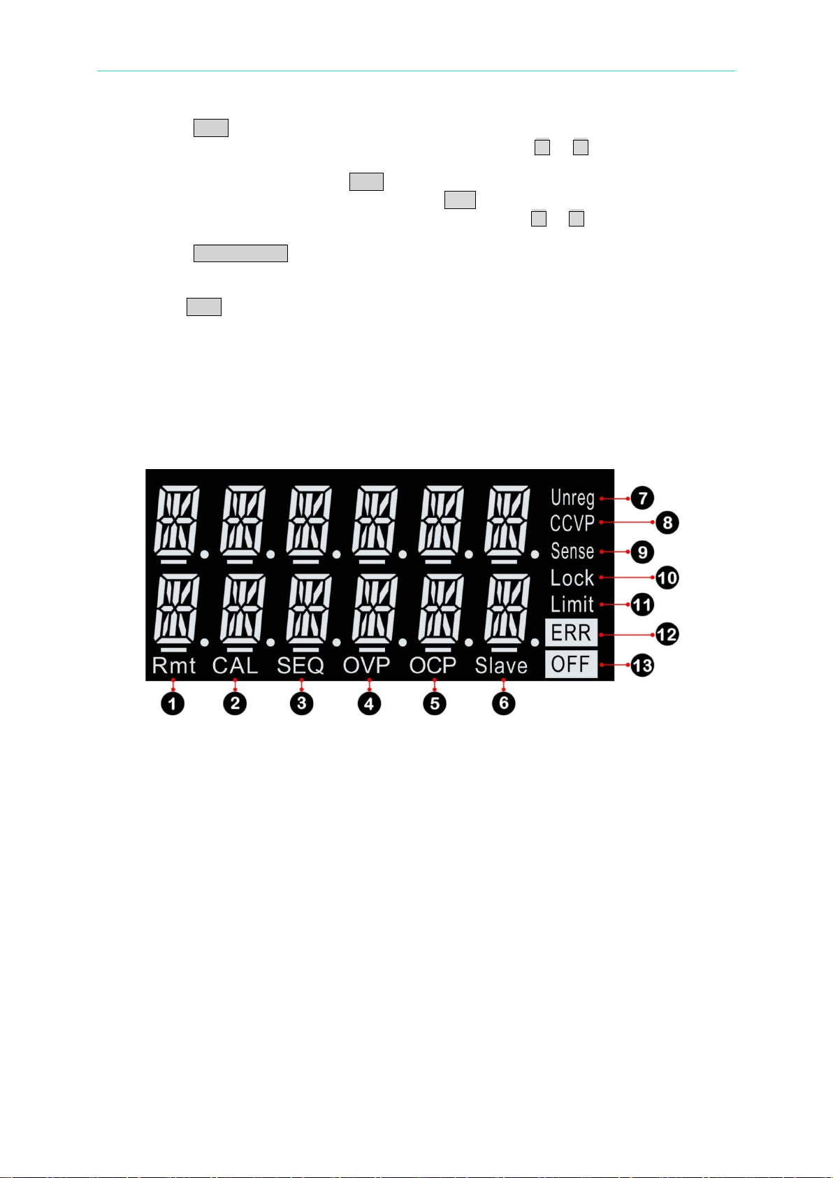
To get familiar with your power supply, you need to familiarize yourself with the display. The
whole display will light up for 3 seconds when the unit is powered on. After two short beeps,
the supply will initialize in t he OUTPUT OFF condition.
1. Rmt: The power supply is in the remote interface mode.
2. CAL: The power supply is in the calibration mode.
3. SEQ: The power supply is in the sequencing mode. You can set the voltage and current
output value and the timing. There are 8 steps to set sequencing values.
4. OVP: When this symbol is lit solidly, t he overvoltage protection function is enabled. If the
OVP it em blinks then the overvoltage protection circuit has caused the power supply to
shut down.
5. OCP: When this symbol is lit solidly, the overcurrent protection function is enabled. If the
OCP item blinks then the overcurrent protection circuit has caused the power supply to
shut down.
6. Slave: When this symbol is lit, the power supply’s status has been set to SLAVE in
parallel or in series (for P9610A only).
7. Unreg: The power supply’s output is unregulated. It’s neither CV nor CC.
8. CV/CC/CP: CV or CC means the power supply is under the constant voltage mode or the
constant current mode, respectively. When CP is lit and exceeding the rated VA under
either the CV or the CC mode, the rated power (For 62010L-36-7: 108W / For
62015L-60-6: 150W) can not be raised any further.
9. Sense: When this symbol is lit, the Remote Sense function is enabled (for 62010L-36-7
only).
2-6
Page 31

Preliminary Check
Note
You can display the following condition after rebooting your power supply. To
support Master/Slave mode, and SEQ mode.
10. Lock: Press the Lock button. The front panel can not be operated until you release the
condition by pressing the LOCK button again.
11. Limit: The display shows the values for the voltage and current limits.
12. ERR: Some hardware or remote interface command errors are detected and the error has
not been cleared.
13. OFF: The power supply’s output is disabled.
show “OUTPUT OFF” on the display, you have to select 0 through the menu
operation of the path, Menu > SYSTEM >STYLE. To show “CV & CC Limit
Setting with lit annunciators, Limit and OFF” you have to select 1 through the
menu operation of the path, Menu > SYSTEM >STYLE. This setting doesn’t
2-7
Page 32

Page 33
Power Supply Operation
3. Power Supply Operation
Please read the following overview of the front panel keys before operating the power supply.
The power supply is configured to front panel operation mode by default before shipment.
While powering on, the power supply automatically enters into the front panel operation
mode. When the power supply is under the remote operation mode, you can return to the
front panel operation mode by pressing the Local button if you didn’t lock the key by
command.
This power supply is autoranging. You can set a desired voltage and current within 0V ~
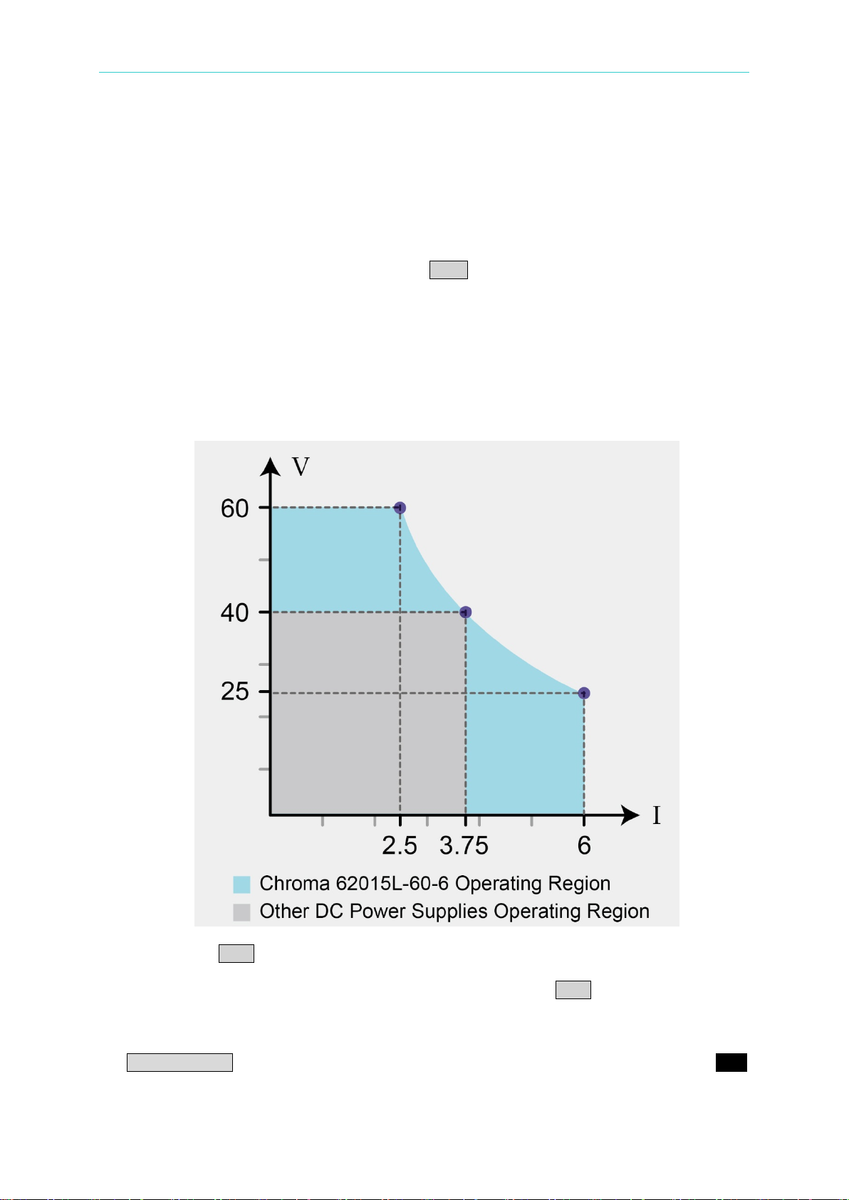
36V, 0A ~ 7A (on the 62010L-36-7) or 0V ~ 60V, 0A ~ 6A (on the 62015L-60-6). The
product of the voltage and current must be less than 108W (62010L-36-7) or 150W
(62015L-60-6). For example, on the P9611A, when the voltage is set to the maximum of
60V, the maximum output current is 150W/60V = 2.5A. For a 40V setting, the maximum
output current is 3.75A. The maximum output power of 150W is available for all Volt/Amp
combinations that lie on the hyperbolic curve in blue as pictured below.
Pressing the Limit button causes the display of the power supply to change to the limit
mode. The present limit values are displayed. Under this mode, you can observe the
change of the limit values by adjusting the control knob. If the Limit button is pressed
again, or if the function times-out in several seconds, the display turns back to th e m eter
mode. The actual output voltage and current will be shown.
The power supply’s output can be enabled or disabled from the front panel by pressing the
Output ON/OFF button. When you turn off the output, the OUTPUT OFF symbols and OFF
are lit on the display.
3-1
Page 34

Programmable DC Power Supply 62000L Series User’s Manual
Note
Under the constant voltage mode, the voltage values between the meter and the
mode, enter the limit mode.
Note
1. To use the control knob to set a desired voltage and current limit, you can use
current in ord er to set the power lower than the rated value.
The display presents operating status and error codes for the power supply. For example,
when an error occurs, the ERR symbol will light up on the display. For more information,
please refer to “2.4.4 Display Check.”
3.1 Constant Voltage Operation
Constant voltage (CV) operation, using the front panel or through remote control, is reviewed
below.
Front Panel Operation:
1. Connect a load to the output terminals: Before turning the power on, connect a load to
the + and – output terminals.
2. Initial tur n on of the power supply: When the power supply is first tur ned on, it disables
the output.
3. Set the limit mode: When the Limit lights up on the display by pressing the Limit button,
the limit mode is entered. You can see the voltage and current limit values on the display.
limit mode are identical. In addition, if the display is under the meter mode, you
are not able to see the change in the current limit value when adj usting the knob.
Therefore, to see the change in the current limit value in the constant voltage
4. Use the knob to set the desired current limit: Press the Limit button on the front panel
and set the knob to current control by pressing the V/A button. The cursor under the first
digit of the ammeter flashes. You can change the flashing cursor using the or
buttons, and adjust the value to the desired current limit by turning the knob. The limit
setting is disabled and the Limit on the display extinguishes in 5 seconds without any
operations.
5. Use the knob to set the desired voltage limit: Press the Limit button on the front panel
and set the knob to voltage control by pressing the V/A button. The cursor under the
second digit of the voltmeter flashes. You can change the flashing digit using the or
buttons, and adjust the value to the desired output voltage. The limit setting is disabled
and the Limit on the display extinguishes in 5 seconds without any operations.
6. Get back to the meter mode: Press the Limit button or let the display time-out after
several seconds to get back to meter mode.
7. Enable the output: The OFF symbol on the display is turned off by pressing Output
button. Then, OVP, OCP, and CV light up. The display goes into the meter mode. Under
this mode, the display shows the actual output voltage and current.
8. To make sure that the power supply is under the constant voltage mode: If you
operate the power supply under the constant voltage (CV) mode, make sure that the CV
on the display is lit. If the CC on the display is lit, pleas e select a higher current limit.
the or buttons to move the flashing cursor to a desired location.
2. If a load change during actual CV operation causes the current limit to be
exceeded, the power supply will automatically adjust the constant current,
and the output voltage will drop in proportion.
3-2
3. When the VA value from setting the meter mode or t he limit mode exceeds
the rated power like 108W on the 62010L-36-7, or 150W on the 62015L-60-6,
the limit signal on the display will flash until you decrease the voltage or the
Page 35

Power Supply Operation
Note
Under the constant current mode, the current values between the meter and the
mode, enter the limit mode.
Note
1. To use the knob to set a desired voltage and current limit, you can use the
2. If a load change during actual CC operation causes the voltage limit to be
Remote Operation:
CURRent {<current> |MIN| MAX}
This command sets the current.
VOLTage {<voltage> |MIN|MAX}
This command sets the voltage.
OUTPut ON
This command enables the output.
3.2 Constant Current Operation
Constant current (CC) operation, using the front panel or through remote control, is reviewed
below. The relative operation buttons are the same as the ones at section 3.1.
Front Panel Operation:
1. Connect a load to the output terminals: Before turning on the power, connect a load to
the + and – output terminals.
2. Initial turn on of the power supply: When the power supply is first turned on, it disables
the output.
3. Set the limit mode: When the Limit flashes on the display, the li mit mod e is entered. You
can see the voltage and current limit values on the display.
limit mode are identical. In addition, if the display is under the meter mode, are
not able to see the change in the voltage limit value when adjusting the knob.
Therefore, to see the cha nge in the voltage limit value in the constant current
4. Use the knob to set the desired current limit: Press the Limit button on the front panel
and set the knob to current control by pressing the V/A button. The cursor under the first
digit of the ammeter flashes. You can change the flashing cursor using the or
buttons, and adjust the value to the desired current limit by turning the knob. The lim it
setting is disabled and the Limit on the display ext ing uishes in 5 seconds without any
operations.
5. Use the knob to set the desired voltage limit: Press the Limit button on the front panel
and set the knob to current control by pressing the V/A button. The cursor under the
second digit of the voltmeter flashes. You can change the flashing digit using the or
buttons, and adjust the value to a desired output voltag e. The limit setting is disabled, and
the Limit on the display extinguishes in 5 seconds without any operations.
6. Get back to the meter mode: Press the Limit button or let the display time-out after
several seconds to get back to meter mode. Then the Limit on the display turns off, and
the display shows “OUTPUT OFF.”
7. Enable the output: The OFF on the display is turned o ff. Then OVP, OCP, and CC are lit.
The display goes into the meter mode. Under this mode, the display shows the actual
output voltage and current.
8. To make sure that the power supply is under the constant current mode: If you
operate the power supply under the constant current (CC) mode, make sure that the CC
on the display is lit. If the CV on the display is lit, choose a hig her voltage limit.
or buttons to move the flashing cursor to the right or left.
3-3
Page 36

Programmable DC Power Supply 62000L Series User’s Manual
exceeded, the power supply will automatically adjust the constant voltage,
current in ord er to set the power lower than the rated value.
Note
The 62015L-60-6 has the factory default, OVP Level: 66V/OVP ON/OCP L e vel:
6.6A/OCP ON/Voltage Limit: 0V/Current Limit: 6A.
and the output current will drop in proportion.
3. When the VA value from setting the meter mode or t he limit mode exceeds
the rated power like 108W on the 62010L-36-7, or 150W on the 62015L-60-6,
the limit signal on the display will flash until you decrease the voltage or the
Remote Operation:
VOLTage {<voltage> |MIN|MAX}
This command sets the voltage.
CURRent {<current> |MIN| MAX}
This command sets the current.
OUTPut ON
This command is applied to enable the output.
3.3 Storing and Recalling Operation States
The power supply can remember 16 different operating states in non-volatile memory. An
operating state contain s CV limit, CC limit, OVP trip level, OVP ON/O F F state, OCP trip level
and OCP ON/OFF state. Location 0 is the power-on state. You can recall one of t he saved
states through the front panel or remote control. The reset state (62010L-36-7’s factory
default - OVP Level: 39.6V/OVP ON/OCP Level: 7.7A/OCP ON/Voltage Limit: 0V/Current
Limit: 3A) is initially saved in the locations from 0 to 15. You might use the following
procedures to store and recall an operating state.
Storing an Operating State via the Front Panel
1. Press the Store button.
2. Rotate the knob and select a location from 0 to 15, where you want to save your settings.
You can use or buttons to review the settings stored in the selected location.
3. Press the Store button to store active operating state. If you want the settings you define
as the power-on state, save your settings in Location 0.
4. To abort the storing operation, press any other button except the Store button.
Recalling a Stored State via the Front Panel
1. Press the Recall button.
2. Rotate the knob and select the stored location you want. You can use or buttons to
review the settings stored in the selected location.
3. Press the Recall butt on once again to recall the stored settings.
4. To abort the recall operation, press any other button except the Recall.
Remote Operation:
*SAVE {0|1|…|15}
Save an operating state to a specified location.
*RCL {0|1|…|15}
Recall a stored state from a specified location.
3-4
Page 37

Power Supply Operation
Note
The OVP circuit contains a crowbar SCR, which efficiently shorts the output of
3.4 Setting the Overvoltage Protectio n
The overvoltage protection is designed to prevent the load from output voltages that reach a
specified value greater than the defined protection value. To accomplish the OVP, the output
is shorted via an internal SCR w hen the trip level i s set greater than 3V or by programming the
output to 1V when the trip level is set to less than 3V.
The following procedures show how to set the OVP trip level, how to check OVP operation,
and how to clear overvoltage condition.
To set the OVP level and enable the OVP circuit via the Front Panel
1. Turn on the power supply: When the power supply turns on, it goes into a disabled
output state.
2. Get into the OVP menu and set a desired trip level: Press the OVP key. You will see
LEVEL 39.60V/66V on the 62010L-36-7/62015L-60-6 display. Press the or buttons
to move the cursor and adjust the control knob for a desired OVP trip level. The trip levels
can be set within 0V to 39.6V/66V.
3. Enable the OVP circuit: Press OVP key again. The OVP with the blinking ON symbols
shows on the display. Press the same button once again to finish. The power supply will
exit the OVP menu and the display will return to the meter mode. Then you will see the
OVP lit at the bottom of the display.
4. Exit the OVP menu without saving: Before applying the above procedure, you can
press any other key to exit from the present OVP settings, which will not be saved in the
non-volatile memory.
Inspecting the OVP settings via the Front Panel
To inspect OVP operation, increase the output voltage to near the trip point. Then raise the
output by rotating the knob until the OVP circuit trips. This operation will cause the power
supply output to drop to zero, the OVP on the display will blink, and the CV symbol will light.
The OVP TRIP message is displayed immediately.
Clearing the overvoltage condition via the Front Panel
If the OVP Trip symbol appears, and this condition is caused by an external voltage source
like a battery, disconnect the source first. The following procedures show you how to clear the
overvoltage condition and revert to the normal mode operation.
1. Set the OVP trip level: Press the OVP button and raise the OVP trip level with the knob
so that the trip level’s value is higher than the output level. To review the output voltage
value, you can press the Limit button.
2. Move to the clear mode: Press the OVP button. The OVP symbol will blink ON.
3. Clear OVP and exit the settings: Rotate the knob clockwise in order to see the blinking
CLEAR symbol. Press the OVP button again to clear the previous memorized OVP value.
The output will return to the meter mode.
Remote Operation:
VOLT:PROT {<voltage>|MIN|MAX}
Set the OVP level.
VOLT:PROT:STAT {OFF|ON}
Disable or enable the OVP circuit.
VOLT:PROT:CLE
Clear the tripped OVP circuit.
3-5
Page 38
Programmable DC Power Supply 62000L Series User’s Manual
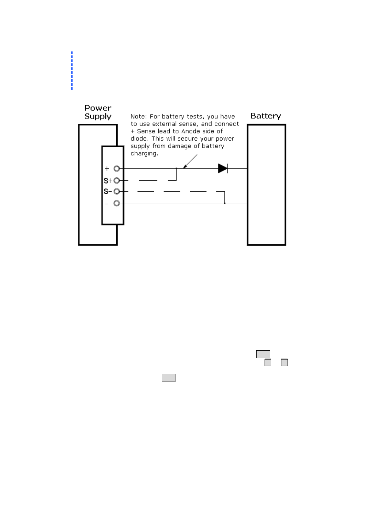
the power supply once the overvoltage condition occurs. If the output of your
series with the output as shown below.
power supply connects an external voltage source such as a battery, the SCR
will continuously sink a large amount of current from the source and possibly
damage the power supply. To avoid the damage, a diode must be connec ted in
3.5 Setting the Overcurrent Protection
The overcurrent protection is designed to prevent the load from output currents that reach a
specified value greater than the defined protection value.
The following procedures show how to set the OCP trip level, how to check OCP operation,
and how to clear the overcurrent condition.
Setting the OCP level and enabling the OCP circuit via the front panel
1. Turn on the power supply: When the power supply first turns on, the output is disabled.
2. To get into the OCP menu and set a desired trip level: Press the OCP button once, you
will see the LEVEL 7.70A/6.6A on the P9610A/11A display. Press the or buttons to
move the cursor and adjust the control knob for a desired OCP trip level.
3. Enable the OCP circuit: Press the OCP button once again. The OCP symb ol will blink
ON. Press the same key to finish. The power supply will exit the OCP menu and the
display will return to the meter mode. Then you can see the OCP lit at the bottom of the
display.
4. Exit the OCP menu without saving: Before applying the above procedure, you can
press any other key to exit from the OCP changing operation. The conditions will not be
saved.
Inspecting the OCP settings via the front panel
To inspect OCP setting, increase the output current to near the trip point. Then raise the
output by rotating the knob until the OCP circuit trips. This operation will cause the power
3-6
Page 39

Power Supply Operation
Note
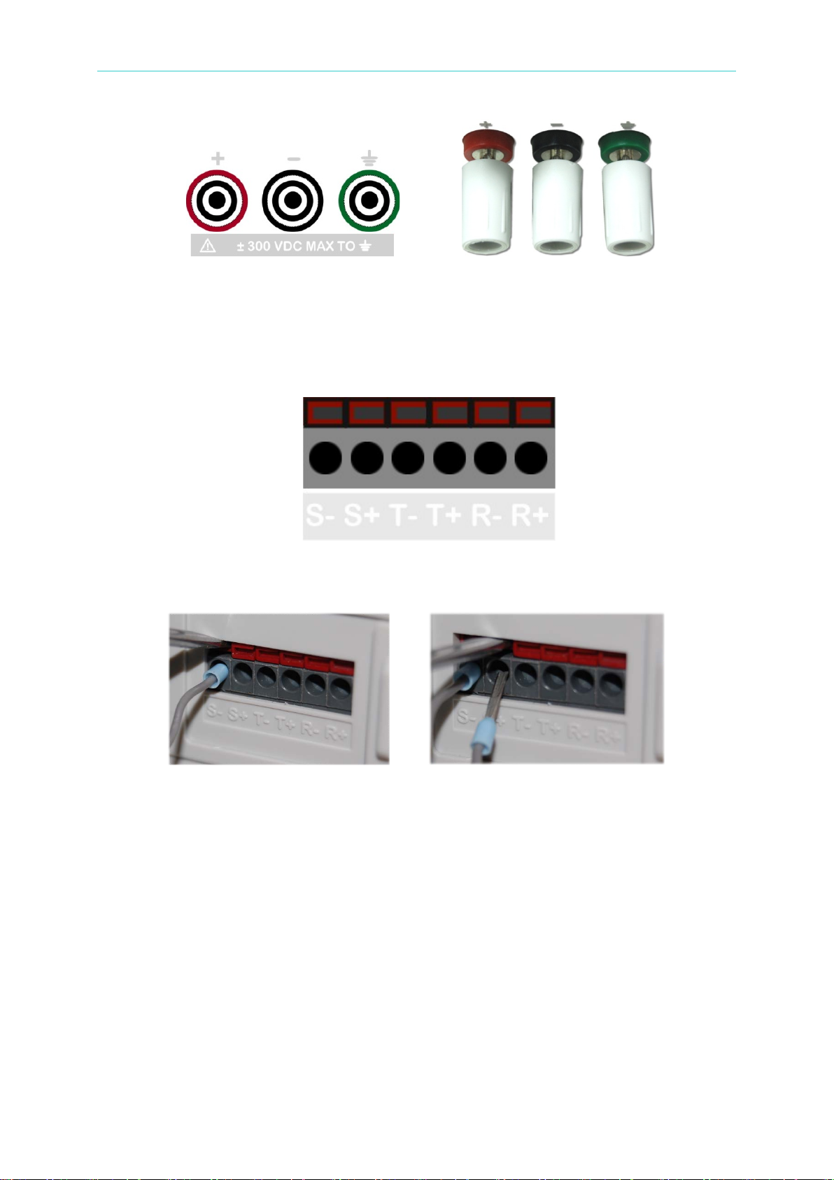
When you use bare leads to connect the power supply, please rotate the + & leads’ insertion. Then rotate the terminals clockwise to fasten the connection.
supply output to drop to zero and the OCP symbol will start to blink. The OCP TRIP message
will be displayed immediately.
Clearing the overcurrent condition via the front panel
When the OCP Trip appears, and if it was caused by an external voltage source like a battery,
disconnect the source first. The following procedures show you how to clear the overcurrent
condition and revert to the normal mode operation.
1. Set the OCP trip level or the output current level: Press the OCP button once and raise
the OCP trip level with the knob. The trip level’s value has to be higher than the output
level.
2. Move to the clear mode: Press the OCP button once. The OCP symbol will blink ON.
3. Clear OCP and exit the settings: Rotate the knob clockwise to see the blinking CLEAR
symbol. Press the OCP button once again to clear the previously memorized OCP value.
The output will return to the meter mode.
Remote Operation:
CURR:PROT {<current>|MIN|MAX}
Set the OCP level.
CURR:PROT:STAT {OFF|ON}
Disable or enable the OCP circuit.
CURR:PROT:CLE
Clear the tripped OCP circuit.
3.6 Remote Sensing (for 62010L-36-7 only)
Remote Sensing is applied to keep regulation from degrading which might occur due to the
voltage drop between the output connection of the power supply and the load.
After connecting the power supply to the load, voltage is sensed at the load r ather than at the
power supply’s output terminals. This connection allows the power supply to generate
sufficient voltage to the load automatically due to the voltage drop in applications with long
lead lengths, and read back an accurate voltage directly over the load.
When the Remote Voltage Sense is applied, the OVP circuit senses the voltage at the load
terminals, not the power supply output terminals.
How to use Remote Voltage Sense
There are three steps to using the Remote Voltage Sense. First of all, the output + and – of
the P9610A have to be wired to your DUT’s + and - terminals. Second, the sense + and – of
the P9610A have to be wired to your DUT’s + and - terminals. Third, you need to enable the
sense option via the front panel.
1. Wire the 62010L-36-7’s output to your DUT:
You can connect the output + & – of the power supply, and DUT’s + & - through either
banana leads, or bare leads.
terminals of the power supply counter-clockwise to release so me spaces for bare
3-7
Page 40
Programmable DC Power Supply 62000L Series User’s Manual
Connection via Banana Leads Connection via Bare Leads
2. Wire t he 62010L-36-7’s sense to your DUT:
The terminals of the positive sense (S+) and the negative sense (S-) are located with the
terminals of the positive transfer (T+), the negative transfer (T-), the positive recipient (R+),
and the negative recipient (R-). The terminals (T+/T-/R+/R-) are used for Master-Slave
control.
To wire the sense terminal of your power supply, you need t o use a screwdriver with a flat
head whose diameter is equivalent to or less than 3 millimeters. With the screwdriver
pressing on the red area, you can insert a lead into the terminal as shown below.
Negative Sense Connection Positive Sense connection
3. Enable the sense via the front panel operation:
To enable the remote sense, you have to turn off the output first and press the Menu
button once. The SENSE symbol will blink. Press the Menu button once again. The
display will show a blinking INT. Rotate the knob to display the blinking EXT symbol.
Press the Menu button to finish the setting. The output will return to the meter mode. The
sense signal will light at the right side of the display as shown below. To exit the
configuration session, press any other key to exit.
3.6.1 Constant Voltage Regulation
The constant voltage (CV) regulation specification for load applications applies at the output
terminals of the power supply. Under the Remote Voltage Sense, you have to add 5mV to this
specification for each drop of 1V between the positive load point and + output terminal of the
power supply since the load current is changed. For this potential issue, the lead length has to
3-8
Page 41

Power Supply Operation
Note
Don’t use the shield as one of the sense conductors.
be taken into account. It is important to keep the resistance of the sense leads at or below
0.5Ohm for each lead in order to meet the above-specified performance.
3.6.2 Output Rating
The rated output voltage and current specifications apply at the output terminals. When using
Remote Voltage Sense, any voltage dropped along the load leads has to be taken into
account and added to the load voltage in order to achieve the correct output voltage. However,
the performance specifications cannot be assured when the maximum output voltage at the
output terminals is exceeded. In the event this occurs, UNREG will be shown on the display.
3.6.3 Output Interference
Any interference (noise) occurring on the sense leads also appears at the output of the power
supply. This may affect the voltage load regulation as well. To minimize external noise, it is
better to twist the sense leads, and run them in pa rallel and close to the load leads. The sense
leads must be shielded in any case, and the shield must be grounded at the pow er supply end
only.
3.6.4 Stability
When you use the external sense under certain combinations of load lead lengths, and large
load capacitances, a filter may be created as part of the voltage feedback loop. In addition,
the extra phase shift generated by this filter can decrease the power supply’s stability, slowing
down the transient response. In extreme cases, it may cause power supply oscillations. To
minimize this potential issue, keep the load leads as short as possible and twist them together.
When the remote sense leads are used, various adverse effects can occur as a result of
accidental open-connections of the sense or load leads during external sense operation. To
avoid these effects, please provide secure permanent connections.
3.6.5 Remote Sensing Connections
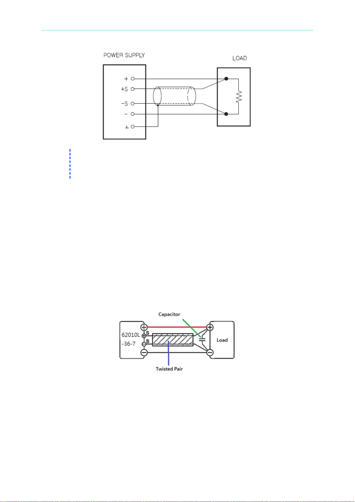
Remote Sensing needs to connect the load leads from the output terminals to the load and
the sense leads from the sense terminals to the load as shown below.
3-9
Page 42
Programmable DC Power Supply 62000L Series User’s Manual
Note
1. For voltage sense connections, the sense leads have to be connected to the
recommended you to turn off the power supply.
output terminals.
2. Before the connecting the external sense connections, we strongly
Wire Shielding & Load Line Impedance
When wiring any loads with the 62010L-36-7, some rules have to be kept in mind.
1. If the wiring to a load is long, the phase shift caused by the inductance and capacitance of
the wiring becomes non-negligible, and then causing oscillation. In that case, the
capacitor prevents oscillation.
2. If the load current changes to pulse form in a sud den, the ou tput volta ge may i ncrease due
to the effects from the inductance component o f the wiring. In that case, the capacitor also
prevents variations via output.
3. Twisting the load wires is able to reduce the inductance component, and stabilize the
output.
4. Use a capacitor whose withstand voltage is greater than or equal to 120% of the units
rated voltage.
5. When you finish using the remote sensing function, please remove the sensing wires, and
make su re to turn off the remote sensing by setting the sense state to INT (internal).
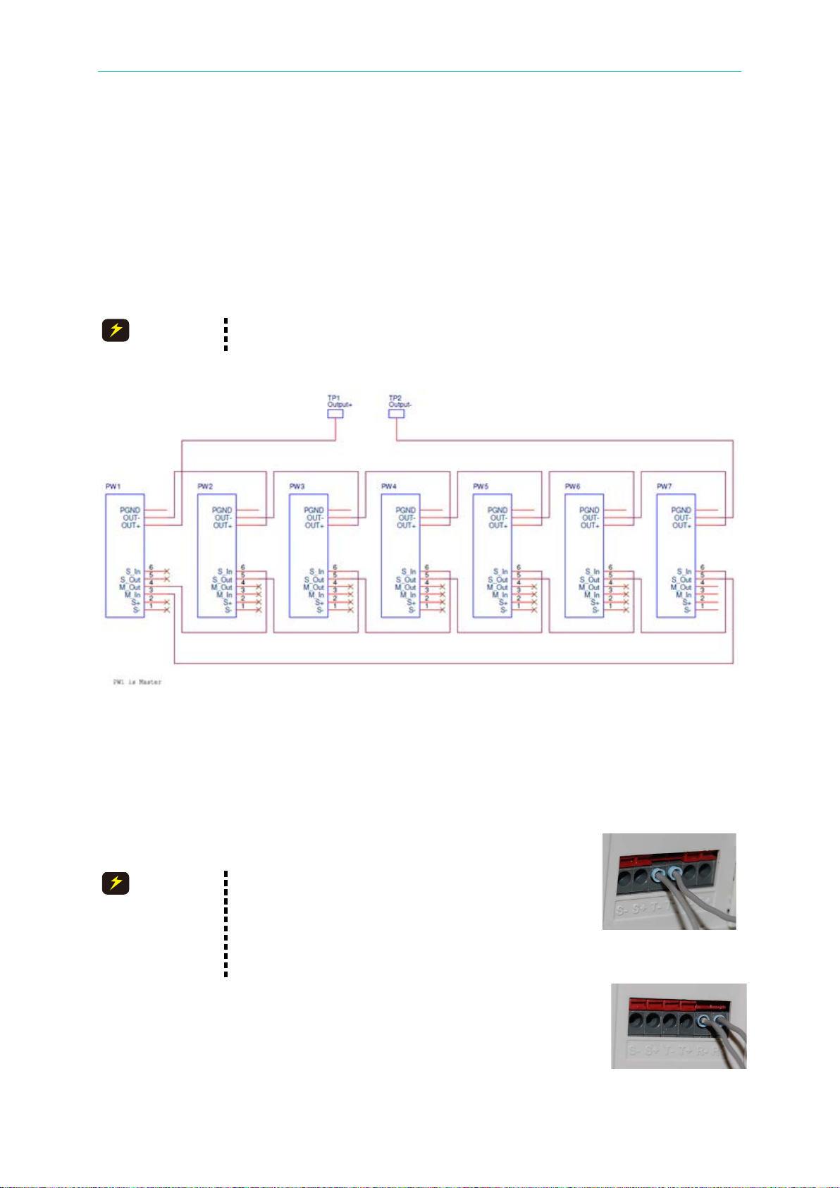
3.7 Master & Slave Application (62010L-36-7 Only)
If you have applications that need voltages and currents greater than the rated maximum
outputs, you can achieve this using multiple power supplies. The power supply can output an
extended range of voltages or currents by connecting more units. Up to 7 units, limited to the
same model, in series or in parallel may be connected if your application requires higher
output voltage or current, such as greater than 36V (up to 252V) or greater than 7A (up to
49A).
3-10
Page 43
Power Supply Operation
When power supplies operate in series, it can not enable remote
sensing function.
1. When making the series connection, please do
is seven (7).
CAUTION
CAUTION
Slave Unit
Master Unit
3.7.1 Connections in Series
To output voltage in the 36V to 252V range, connect two or more power supplies in series.
Series connections can be utilized up to the output isolation rating of any power supply in
order to obtain a higher voltage than that available from a single power supply. These series
connected power supplies can be operated with one load across both power supplies or with
a separate load for each power supply. The power supply has a reverse polarit y diode
connected across the output terminals. That means if operated in series with other power
supplies, damage will not occur if the load is short-circuited or if one of the power supplies is
turned on separately from its series partner.
The connection diagram for series connections is illustrated below.
How to accomplish series connections:
For example, in order to connect 3 units (62010L-36-7) in series to output 108V, follow the
procedures below. There a re three steps.
1. Control signal connection
Connect T+ (Master) to R+ (Slave1), R- (Slave1) to R+ (Slave2), and R(Slave2) to T- (Master). This setup concept is al way s used i f you w ant to
make up other output systems with two or more P9610As.
not wire the sense to your DUT (Device under
Test) in order to prevent any internal circuit
damage from high voltage coming from the DUT.
2. The maximum number of series or parallel units
2. Output terminal connection
Connect the Master output + to the DUT +, the Master output - to the
Slave1 output +, the Slave1 output - to the Slave2 output +, and the
Slave2 output - to the DUT - to form the connection in series. The
connection with reversed polarities, such as the Master output connected
3-11
Page 44
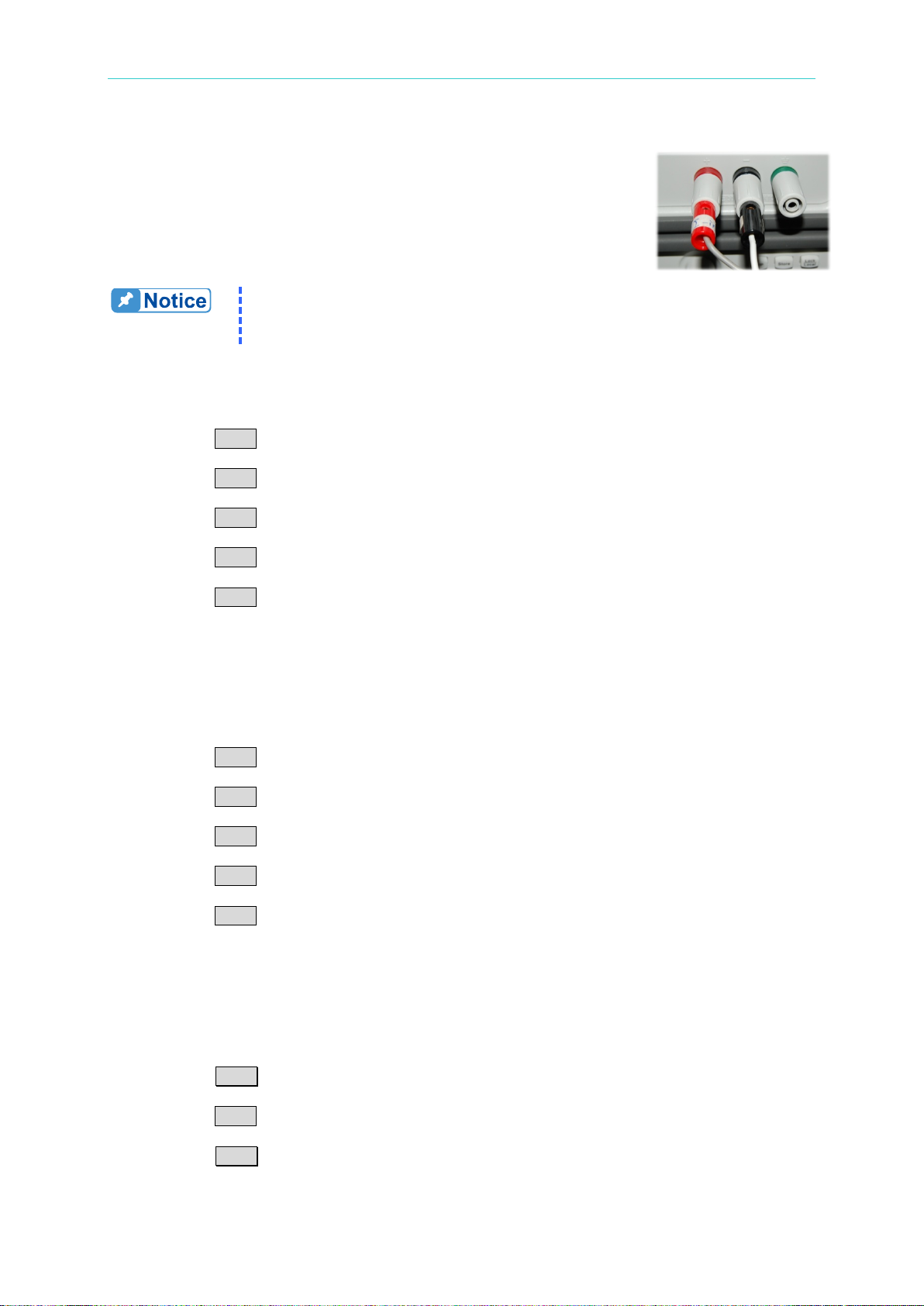
Programmable DC Power Supply 62000L Series User’s Manual
The sum won’t be shown on the display. You have to calculate this for
output value.
Output Connection
to the DUT - and so on, is also available.
3. Master/Slave mode Setup
When the connection in series is used, the output voltage is the sum of
the voltages from the connected power supplies. Each of the indiv idual
power supplies must be properly set in order to obtain the total output
voltage.
yourself or prepare a load (or a meter) to inspect and confirm the total
● Master Unit (Quantity X 1):
This setup requires only 1 unit. Before setting this unit to the Master, disable the output.
1. Press the Menu button.
2. Rotate the Knob to show MA/SL on t he display.
3. Press the Menu button to confirm.
4. Rotate the Knob to show SETUP on the display.
5. Press the Menu b utton to c onfirm.
6. Rotate the Knob to show MODE on the display.
7. Press the Menu button to confirm.
8. Rotate the Knob to show S-MA on the display.
9. Press the Menu button to finish the settings.
10. To qu it the configuration, press any other key to exit.
● Slave Unit (Quantit y X 1 to 6):
The buttons used are the same as the ones used for setting the master unit. This connection
requires at least 1 unit, and at most 6 units. For exam ple: If two slave units are required, each
unit has to be set to the slave state. Before setting this unit to Slave, disable the output.
1. Press the Menu button.
2. Rotate the Knob to show MA/SL on t he display.
3. Press the Menu button to confirm.
4. Rotate the Knob to show SETUP on the display.
5. Press the Menu b utton to c onfirm.
6. Rotate the Knob to show MODE on the display.
7. Press the Menu button to confirm.
8. Rotate the Knob to show S-SL on the display.
9. Press the Menu button to finish the settings.
10. To qu it the configuration, press any other key to exit.
● STATE ON:
To activate the Master-Salve function using a series connection, you have to enable the state
from OFF to ON through the following procedures. When the slave state is enabled, the Slave
signal will show at the bottom right like the picture “Slave State.” However, when the master
state is enabled, there is no signal shown at the bottom right.
1. Press the Menu button.
2. Rotate the Knob to show MA/SL on t he display.
3. Press the Menu button to confirm.
4. Rotate the Knob to show STATE on the display.
5. Press the Menu button to confirm.
6. Rotate the Knob to show ON on the display.
3-12
Page 45
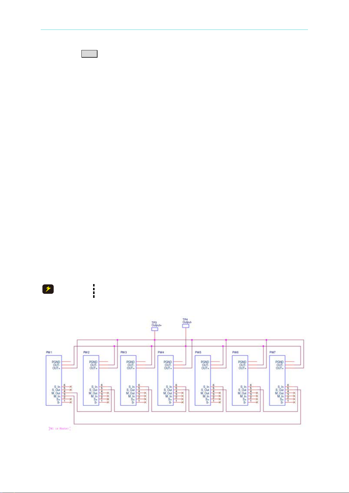
Power Supply Operation
When power supplies operate in parallel, there must less than three of
power supplies can enable remote sensing function.
CAUTION
7. Press the Menu button to finish the settings.
To quit the configuration, press any other key to exit.
When the above settings are done, but before enabling the output on the master unit, the
display on the master unit should display S-MA OFF and slave unit should show S-SL OFF as
in the picture to the right side.
Unit 1, set the slave condition to the output off state.
Unit 2, set the slave condition to the output off state.
Unit 3, set the slave condition to the output off state.
After enabling the output on the master unit, the display on the master unit shows a voltage
value and a current value. On the display of the salve units , only a voltage value will be
shown.
Unit 1, set the master condition to the output on state.
Unit 2, set the slave condition to the output on state.
Unit 3, set the slave condition to the output on state.
3.7.2 Connections in Parallel
To output current within the 7A to 49A range, parallel operation of two or more power supplies
is necessary. Using parallel connections, CV/CC capability, and the automatic crossover
operation, you can obtain a total output current greater than that available from single power
supply. The total output current is the sum of the currents from the connected power supplies.
The output of each power supply can be set separat ely. The output voltage controls of the
Master power supply should be set to the desired output voltage. The Slaves will work in CC
mode with the CC Limit the same as the master output current.
The connection diagram in parallel is illustrated below.
3-13
Page 46
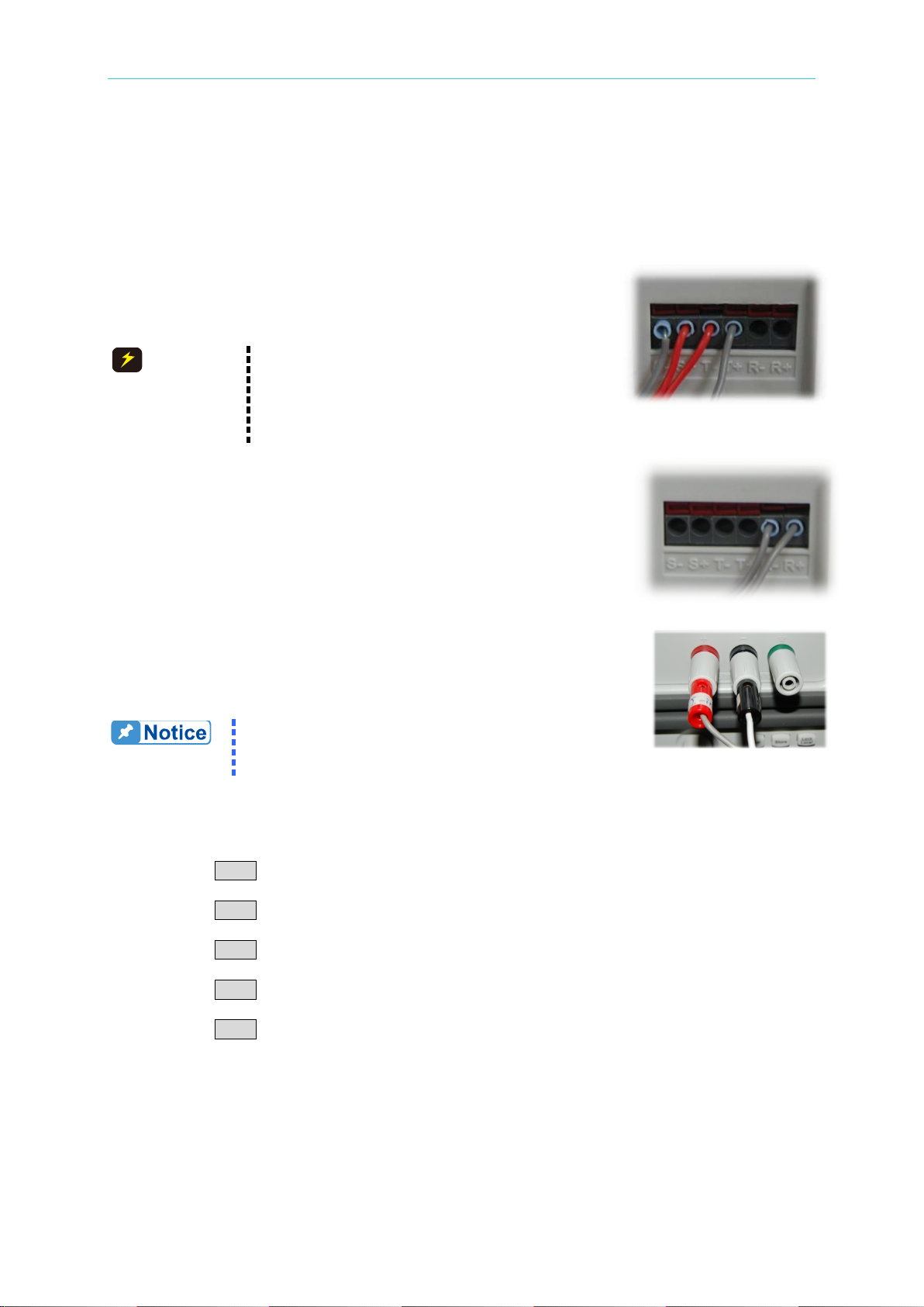
Programmable DC Power Supply 62000L Series User’s Manual
1. When making the series connection,
units at most.
The sum will not be shown on the display. You have
meter) to inspect the total output current.
CAUTION
Master Unit
Slave Unit
Output Connection
How to connection power supplies in parallel:
For example, to connect 3 units in parallel for to output 21A, please follow the procedures
below. There are three parts to the setup.
1. Control signal connection
Connect T+ (Master) to R+ (Slave1), R- (Slave1) to R+ (Slave2), and R- (Slave2) to T(Master). Then connect S+ (Master) to the positive side of the DU T
(Device under Test), and S- (Master) to the negative side of the
DUT. This setup concept is always used if you want to make up
other output systems with two or more 62010L-36-7s in parallel.
please wire the sense to your DUT to do
the necessary current compensation.
2. Each control system can use seven (7)
2. Output terminal connection
Connect the Slave2 output - to the Slave1 output -, the Slave2
output + to the Slave output +, the Slave1 output – to the Master
output -, the Slave1 output + to the Master output +, the Master
output – to the DUT -, and the Master output + to the DUT + to form
the connection in parallel.
3. Master/Slave mode Setup
When the connection in parallel is used, the output current is the sum
of the currents from the connected power supplies. Each of the
individual power supplies must be properly set in order to obtain the
total output current.
to calculate that yourself or include a load (or a
● Master Unit (Quantity X 1):
The buttons used are the same as the ones for setting the units in series. This setup requires
only 1 unit. Before setting this unit to Master, disable the output.
1. Press the Menu button.
2. Rotate the Knob to show MA/SL on t he display.
3. Press the Menu button to confirm.
4. Rotate the Knob to show SETUP on the display.
5. Press the Menu b utton to c onfirm.
6. Rotate the Knob to show MODE on the display.
7. Press the Menu button to confirm.
8. Rotate the Knob to show P-MA on the display.
9. Press the Menu button to finish the settings.
To quit the configuration, press any other key to exit.
● Slave Unit (Quantit y X 1 to 6):
The buttons used are the same as the ones used for setting the units in series. This
connection requires at least 1 unit and at most 6 units. For example: If t wo slave units are
3-14
Page 47

Power Supply Operation
required, each unit has to be set to the slave state. Before setting this unit to Slave, you have
to disable the output.
1. Press the Menu button.
2. Rotate the Knob to show MA/SL on t he display.
3. Press the Menu button to confirm.
4. Rotate the Knob to show SETUP on the display.
5. Press the Menu b utton to c onfirm.
6. Rotate the Knob to show MODE on the display.
7. Press the Menu button to confirm.
8. Rotate the Knob to show P-SL on the display.
9. Press the Menu button to finish the settings.
To quit the configuration, press any other key to exit.
● STATE ON:
Before enabling the state, you have to disable the output. To activate the Master-Slave
function using parallel connections, you have to enable the state from OFF to ON through the
following procedures. When the slave state is enabled, the Slave signal will be shown at the
bottom right like the picture “Slave State.” However, w hen the master s tate is enabled, there is
no signal shown at the bottom right.
1. Press the Menu button.
2. Rotate the Knob to show MA/SL on t he display.
3. Press the Menu button to confirm.
4. Rotate the Knob to show STATE on the display.
5. Press the Menu b utton to c onfirm.
6. Rotate the Knob to show ON on the display.
7. Press the Menu button to finish the settings.
To quit the configuration, press any other key to exit.
When the above settings are completed, but before enabling the output on the master unit,
the display on the master unit will show P-MA OFF, with P-SL OFF on the slave unit, as
shown in the picture to the right.
Unit 1, set the master condition to the output off state.
Unit 2, set the slave condition to the output off state.
Unit 3, set the slave condition to the output off state.
After enabling the output on the master unit, the display on the master unit shows a voltage
value and a current value. On the display of the slave units, only a voltage value is shown.
Unit 1, set the master condition to the output on state.
Unit 2, set the slave condition to the output on state.
Unit 3, set the slave condition to the output on state.
3.7.3 Other Settings for Multiple Connections
● DELAY: Before setting the DELAY, you have to disable the output. This Delay allows you
to set a delay time for the output/control timing when the P9610A(s) is/are set to the master or
normal mode in a sub-system. When the 62010L-36-7(s) is/are set to th e m aster or normal
3-15
Page 48
Programmable DC Power Supply 62000L Series User’s Manual
mode in a sub-system. When the main system’s output is enabled, the 62010L-36-7
sub-system’s set to the master or normal mode, will be also activated according to the delay
time (at most 60 seconds). In the meantime, the OFF annunciator at the bottom right will blink
until the delay time is up and the display returns to the meter mode. Then the slave unit(s) in
the sub-system can be controlled by the sub-system’s master unit(s), and output the similar
power as the master. This sub-system application can be branched again and again to meet
large system requirements. The procedures for setting the delay time are as follows:
1. Press the Menu button.
2. Rotate the Knob to show MA/SL on t he display.
3. Press the Menu button to confirm.
4. Rotate the Knob to show SETUP on the display.
5. Press the Menu b utton to c onfirm.
6. Rotate the Knob to show DELAY on the display.
7. Press the Menu b utton to c onfirm.
8. Rotate the Knob to show T_ON on the display.
9. Press the Menu button to set a desired delay time.
10. Press the Menu button to finish the settings.
To quit the configuration, press any other key to exit.
● P-MA (Master Settings in Parallel): For parallel systems, the master settings can also be
set the same on the other 62010L-36-7s for sub-system applications. When the main
system’s output is enabled, the P9610A sub-system, set to master mode, will be also
activated in a few seconds according to the delay time setting. The procedures for setting the
P-MA mode are described in the section 3.7.2.
● NORMAL: Before enabling the NORMAL mode, you have to disable the output. Then
select the normal mode through the following procedures. Enabling this mode requires that
you remove the output connections to the other 62010L-36-7(s). The unit(s) under the normal
mode will only have a single output. The control connection from the master unit can exist and
wait for the order to output. When enabling the master’s output, the unit(s) under the normal
mode, after the defined delay time, will go into the meter mode, and limit their output to the
defined voltages and currents according to the limit settings. To chec k the limited value, press
the Limit button once. When the slave function is activated under the NORMAL mode, the
maximum output value on each slave unit follows the present adjustment.
The buttons used are the same as the ones when s et ting the DELAY time.
1. Press the Menu button.
2. Rotate the Knob to show MA/SL on t he display.
3. Press the Menu button to confirm.
4. Rotate the Knob to show SETUP on the display.
5. Press the Menu b utton to c onfirm.
6. Rotate the Knob to show MODE on the display.
7. Press the Menu b utton to c onfirm.
8. Rotate the Knob to show NORMAL on the display.
9. Press the Menu button to finish the settings.
To quit the configuration, press any other key to exit.
● TRACK: Bef ore enabling the track mode, you have to disable the output. When enabling
the track mode, the unit under the track mode will track the master’s voltage. This mode only
works in series connections. The procedures for setting the track mode are as follows:
3-16
Page 49

Power Supply Operation
Note
1. Pressing the V/A button long on the front panel under the SEQ mode in
output condition, the display will show the information of V & A, V & W, or
The buttons used are the same as the ones when s et ting the DELAY time.
1. Press the Menu button.
2. Rotate the Knob to show MA/SL on t he display.
3. Press the Menu button to confirm.
4. Rotate the Knob to show SETUP on the display.
5. Press the Menu b utton to c onfirm.
6. Rotate the Knob to show MODE on the display.
7. Press the Menu b utton to c onfirm.
8. Rotate the Knob to show TRACK on the display.
9. Press the Menu button to finish the settings.
To quit the configuration, press any other key to exit.
3.8 Turning Off the Output
The output of the power supply can be disabled or enabled through the f r ont panel operation
or the remote operation. In addition, you can use the Lock/Local key to limit the output and
prevent inappropriate levels.
Front Panel Operation:
To turn on and off the output, press the Output ON/OFF button. When the output of the
power supply is disabled, the OFF symbol shows on the display. The voltage value is 0V
and the current value is 0.02A. When the output of the power supply is enabled, the OFF
symbol disappears.
The output state is not able to be saved in the non-volatile memory. The default of the
output state is off when you turn on the power supply from the front panel or reset it
through the remote operation.
Remote Operation:
OUTP {OFF|ON}
Disable or enable the output.
Lock/Local Button
To prevent incorrect actions (Lock) or to return to local operation from the remote control
(Local), the Lock/Local button is used.
The Lock/Local button can be used to disable the knob and other buttons so that you can
prevent any unwanted changes. Press this button again to enable the front panel operation. If
active, remote mode usage is also inhibited.
3.9 SEQ (Sequencing Mode)
The 62000L series supports a sequencing mode. This mode allows you to output different
voltages and currents over time. There are 8 steps to the setup. When the SEQ is activated,
the sequence is run from start to finish step-by-step. Before adjusting the sequencing settings,
disable the output.
3-17
Page 50
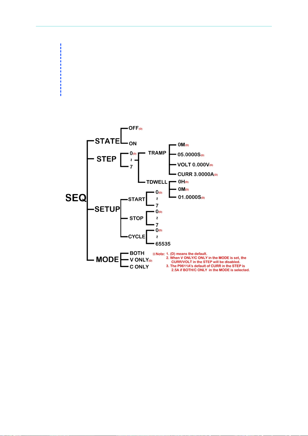
SEQCNT.
(i.e. step 4, step 5, step 6, step 7, step 0 and then step 1).
Programmable DC Power Supply 62000L Series User’s Manual
V & A: The display shows the output voltage and current.
V & W: The display shows the output voltage and power.
SEQCNT: The display shows the rest of the SEQ cycle numbers.
2. If you set the start step at step 1 and the stop step at step 4, the pow er supply
will run in order (i.e. step 1, step 2, s tep 3, and ste p 4). If you set the start step
at step 4, and the stop step at step 1, the power supply will still run in order
Front Panel Operation:
The next figur e of the SEQ family tree of operations on the front panel provides you with an
easy map for setting with the required buttons.
SEQ: Configuration Sequencing Mode parameter menu. You need to disable the output
before using this menu.
STEP: The SEQ’s settings can be saved from step 0 to step 7. In the step settings, you
need to set TRAMP (ramp time) including M (minute), S (second), VOLT (voltage), or
CURR (current), and TDWELL (dwelling time) including H (hour), M (minute), and S
(second)
SETUP: This setting includes START, STOP, and CYCLE.
1. START: Setting the start step of the output sequence. There are 0 ~7 for you to
choose from.
2. STOP: Setting the stop step of the output sequence. There are 0 ~7 for y ou to choose
from.
3. CYCLE: You can set the cycle times between the start and the stop steps. If 0 is used,
the cycling will keep running.
MODE: Setting this MODE affects the voltage and current settings in the sequencing
mode. In the Ramp process, linear interpolation is used.
*. Both: Auto modifies the CV limit and CC limit settings on sequencing step.
*. V ONLY: Auto modifies CV l imit level value on sequencing step. The CC limit value is
the same as CC limit setting.
*. C ONLY: Auto modifies CC l imit level v alue on sequencing s tep. The C V li mit value i s
3-18
Page 51
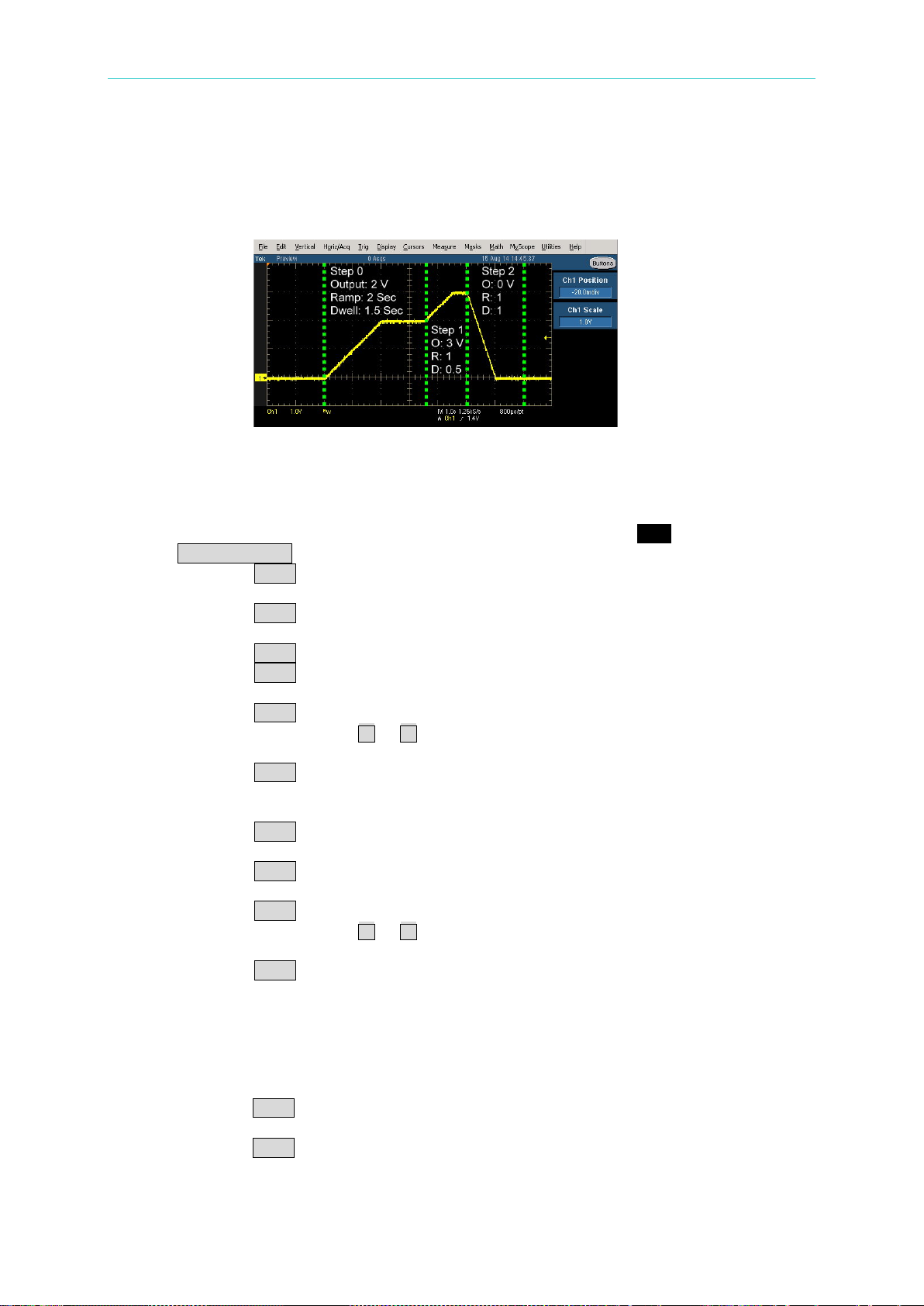
Power Supply Operation
the same as CV limit setting.
STATE: To enable or disable the SEQ mode.
In the following example: There are 3 steps used and shown on the oscilloscope. The dotted
lines in green divide the following waveform into 3 segments. Each segment has its own
setting value.
No Load State
Step 0: 2V, 2 seconds for the ramp time and 1.5 seconds for the dwelling time are set.
The procedures are as follows:
1. Make sure the output is disabled. If the display doesn’t show OFF, please press the
Output ON/OFF button once on the front panel.
2. Press the Menu button.
3. Rotate the Knob to show SEQ on the display.
4. Press the Menu button to confirm.
5. Rotate the Knob to show STEP on the display.
6. Press the Menu b utton to c onfirm. STEP 0 (default) will show on the display.
7. Press the Menu button once to confirm the selection. TRAMP 0M will show on the
display. Then leave 0M in this setting.
8. Press the Menu button once to confirm. TRAMP 00.500S (default) will show on the
display. Then press the or
buttons to move the cursor, and rotate the knob to
set 02.000S.
9. Press the Menu button once to confirm. VOLT 00.000V (default) will show on the
display. Then press the right & le ft direction bu t ton to move the cursor, and rotate the
knob t o set 02.000V.
10. Press the Menu button once to confirm. T DWELL 0H (default) will show on the
display. Then leave 0H in this setting.
11. Press the Menu button once to confirm. TDWELL 0M (default) will show on the
display. Then leave 0M in this setting.
12. Press the Menu button once to confirm. TDWELL 01.000S (default) will show on the
display. Then press the or buttons to move the cursor and rotate the knob to
set 01.500S.
13. Press the Menu button once to confirm. The Menu will return to SEQ menu.
Step 1: 3V, 1 second for the ramp time, and 0.5 seconds for the dwelling time are set.
The setting procedures are similar to those listed in step 0. If you’re familiar with the
setup procedure, please skip the following and set the values directly on the front panel.
1. Rotate the Knob to show STEP on the display.
2. Press the Menu button once to confirm. STEP 0 (default) will show on the display.
3. Rotate the knob to STEP 1.
4. Press the Menu button once to confirm the selection. TRAMP 0M (default) will show
on the display. Then leave 0M in this setting.
3-19
Page 52
Programmable DC Power Supply 62000L Series User’s Manual
5. Press the Menu button once to confirm. TRAMP 00.500S (default) will show on the
display. Then press the or buttons to move the cursor, and rotate the knob to
set 02.000S.
6. Press the Menu button once to confirm. VOLT 00.000V (default) will show on the display.
Then press or button to move the cursor, and rotate the knob to set 02.000V.
7. Press the Menu button once to confirm. TDWELL 0H (default) will show on the
display. Then set 0H in this setting.
8. Press the Menu button once to confirm. TDWELL 0M (default) will show on the
display. Then set 0M in this setting.
9. Press the Menu button once to confirm. TDWELL 01.000S (default) will show on the
display. Then press the or buttons to move the cursor and rotate the knob to
leave 01.500S.
10. Press the Menu button once to confirm. The Menu will return to SEQ menu.
Step 2: 0V, 1 second for the ramp time, and 1 second for the dwelling time are set. The
setting procedures are similar those listed in step 1. If you are familiar with the procedure,
please skip the procedures from 1 to 10 and set the values directly on the front panel. For
procedures 11 to 21, some settings have to be enabled so that the SEQ will r un correctly
according to your settings.
1. Rotate the Knob to show STEP on the display.
2. Press the Menu b utton to c onfirm. STEP 0 (default) will show on the display.
3. Rotate the knob to STEP 2.
4. Press the Menu button once to confirm the selection. TRAMP 0M (default) will show
on the display. Then set 0M in this setting.
5. Press the Menu button once to confirm. TRAMP 00.500S (default) will show on the
display. Then press the or buttons to move the cursor, and rotate the knob to
set 01.000S.
6. Press the Menu button once to confirm. VOLT 00.000V (default) will show on the
display.
7. Press the Menu button once to confirm. TDWELL 0H (default) will show on the
display. Then set 0H in this setting.
8. Press the Menu button once to confirm. TDWELL 0M (default) will show on the
display. Then set 0M in this setting.
9. Press the Menu button once to confirm. TDWELL 01.000S (default) will show on the
display.
10. Press the Menu button once to confirm. The Menu will return to SEQ menu.
11. Rotate the Knob to show SETUP on the display.
12. Press the Menu button once to confirm. START will show on the display.
13. Press the Menu button once to confirm. START 0 (default) will show on the display.
Then set 0 in this setting.
14. Press the Menu button once to confirm. STOP 7(default) will show on the display.
Then rotate the knob to leave 2.
15. Press the Menu button once to confirm. CYCLE 0(default) will show on the display.
Then r otate the knob to set 1.
16. Press the Menu butt on once to c onfirm. T he Menu will return to SEQ menu.
17. Press the Menu button once to confirm. A blinking OFF under STATE shows on the
display.
18. Rotate the knob to ON.
19. Press the Menu button to confirm. The Menu will return to SEQ menu.
20. To quit the configuration, press any other key to exit SEQ menu.
21. Press the Output ON/OFF button once on the front panel and the source will be
output sequentially.
3-20
Page 53

Power Supply Operation
Remote Operation:
OUTPut:SEQuence[:STATe] {0|1|OFF|ON}
Enable/Disable output sequence function.
OUTPut:SEQuence[:STATe]?
Return 0 if output sequence is disabled, and return 1 if output sequence is enabled.
OUTPut:SEQuence:MODE {0|1|2}
Set mode of output sequence. 0 is voltage only. 1 is cur rent only . 2 is for both voltage and
current.
OUTPut:SEQuence:MODE?
Query sequence mode. Return 0, 1 or 2.
OUTPut:SEQuence:CYCLe {<cycle>}
Set output sequence repeat cycle. The value of cycle is 0~65535. 0 means always repeat.
OUTPut:SEQuence:CYCLe?
Query output sequence repeat cycle.
OUTPut:SEQuence:SETup {<start step>},{<stop step>}
Set start step and stop step of output sequence. Step is S0~S7.
OUTPut:SEQuence:SETup?
Query start step and stop step.
OUTPut:SEQuence:STEP:VOLTage {<step>},{<voltage>|DEF|MIN|MAX}
Set voltage of a step. Step is S0~S7.
OUTPut:SEQuence:STEP:VOLTage? {<step>}
Query voltage setup of a step. Step is S0~S7. Return voltage in Volts.
OUTPut: SEQue nce: STEP: CURRe nt {<ste p>},{< curr ent>| DEF|M IN|MA X}
Set current of a step. St ep is S0~S 7.
OUTPut:SEQuence:STEP:CURRent? {<step>}
Query current setup of a step. Step is S0 ~S7. Return current in amp s.
OUTPut:SEQuence:STEP:RAMP {<step>},{<time in ms>|MIN|MAX}
Set ramp time of a step. St ep is S0~S 7. The ramp time allows you to set from 0 to
3599999ms.
OUTPut:SEQuence:STEP:RAMP? {<step>}
Query ramp tim e of a step. Step is S0~S7. Return ramp time in ms.
OUTPut:SEQuence:STEP:DWELl {<ste p>},{<time in ms>|MIN|MAX}
Set width of a step. Step is S0~S7. Maximum dwell is 86399999ms.
OUTPut:SEQuence:STEP:DWELl? {<step>}
Query width of a step. Step is S0~S7. Return dwell in ms.
OUTPut:SEQuence:STEP? {<step>}
Query a step setting. Step is S0~S7.
3-21
Page 54

Programmable DC Power Supply 62000L Series User’s Manual
3.10 System Operations
This section provides information about system such as error message querying, beep
settings, display control, OCP delay setting, Style and power supply identity querying. Most of
the items in System Operation pr ovide informati on for serv i cing procedures.
3.10.1 Error States
Once an error occurs, the ERR indicator is lit. Errors can be generated by invalid operat ion or
hardware failure. A record with up to 32 errors is saved in the power supply’s error queue. For
more information, please refer to the following instructions and the chapter “Error Messages
Errors are retrieved in a first-in-first-out (FIFO) sequence. The first returned error is the
first saved error. When all of errors are read from the queue, there will be no ERROR
symbol shown on the display.
When more than 32 errors have occurred when operating the power supply over the
remote control, the last error saved in the queue (the most recent error) will be replaced
with -350,Too many errors. After removing the errors from the queue, you can save the
next error. If there is no error when you read the error queue, the power supply shows
“NO ERROR” on the display, or responds with +0,No errors over the remote control.
You can clear the error queue when turning off the power supply or after commanding a
*CLS (Clear Status). Please note that the *RST (Reset) doesn’t clear the error queue.
Front Panel Operation:
To check and remove error message(s), please follow the procedures below.
1. Press the Menu button once. Rotate the knob to the SYSTEM.
2. Press the Menu button once to confirm. A blinking ERROR will show on the display.
3. Press the Menu button once to check the error message, such as -221 at the upper line,
and SETTINGS CONFLICT at the bottom line in scrolling text. If there are still other error
message(s), repeatedly pressing the Menu button will read and clear the errors stored in
the queue. After the last press, NO ERROR will appear on the display.
Remote Operation:
SYST:ERR?
Read an error from the error queue.
.”
3.10.2 Beep/Alarm Settings
Beeps are used to indicate a front panel operation (button pressing or knob rotating) is
detected or to alarm an unexpected condition (OVP/OCP tripped) occurs. You can chan ge the
beep behaviors.
The NORMAL beep is used to indicate a front panel operation (button pressing or knob
rotating) is detected. By default the NORMAL beep is ON.
The ALARM is used to alarm an OVP/OCP is tripped. By default the ALARM is OFF. If
the OVP/OCP alarm is enabled, a continuous buzzer sound is generated if the OVP/OCP
is tripped until the OVP/OCP trip condition is clear.
3-22
Page 55

Power Supply Operation
Front Panel Operation:
1. Press the Menu button once. Rotate the knob to the SYSTEM.
2. Press the Menu button once to confirm. Rotate the knob to the beep.
3. Press the Menu button once to confirm. A blinking NORMAL/ALARM will show on the display.
4. Press the Menu button once to confirm. A blinking ON will show on the display.
5. Rotate the knob to the OFF selection.
6. Press the Menu button once to finish the settings.
7. To quit the configuration, press any other key to exit.
Remote Operation:
SYST:BEEPer:NORMal[:STATe] {0|1|OFF|ON}
Commanding 0 or OFF, will disable the beep. Commanding 1 or ON will enable the beep.
SYST:BEEPer:NORMal[:STATe]?
Query the present state of the beeper.
SYST:BEEPer:ALARm:OVP[:STATe] {0|1|OFF|ON}
Commanding 0 or OFF will disable the OVP alarm. Commanding 1 or ON enables the alarm.
SYST:BEEPer:ALARm:OVP[:STATe]?
Query the present state of the alarm for the OVP.
SYST:BEEPer:ALARm:OCP[:STATe] {0|1|OFF|ON}
Commanding 0 or OFF disables the OCP alarm. Commanding 1 or ON enables the alarm.
SYST:BEEPer:ALARm:OCP[:STATe]?
Query the present state of the alarm for the OCP.
3.10.3 Display Control
The display control allows you to turn ON/OFF the di splay or display a m essage on the screen
via remote operation. This feature only affects when the power supply is u nder remote con trol.
After the display is turned off, there are no message shown on the display and all
indicators should be lit on local operation will not lit anymore. Only the ERR indicator will
be lit once an error occurs.
You can set a string (up to 49 characters) to show on the display. Lim it ed by the display
digits, the string is scrolling if it is longer than 6 ch aracters. Only al phanumeric characters
and ‘-’ can be displayed and all letters will be change to uppercase letters. Characters
that can not be shown will be replaced with a space.
The display is enabled again and the displaying string is cleared while the power supply
is back to local operation.
Remote Operation:
DISPlay {OFF|ON}
Disable/enable the display.
DISPlay:TEXT <quoted string>
Display a string in the screen. The string must be enclosed in quoted. For example,
DISPlay:TEXT “HELLO WORLD” will show “HELLO WORLD” on the screen
DISPlay:TEXT:CLEar
Clear the displayed message.
3-23
Page 56
Programmable DC Power Supply 62000L Series User’s Manual
3.10.4 OCP Delay (OCPDEL) Settings
If the OCP level is set to a value less than the CC limit, the inrush current upon output turning
on can easily cause an OCP trip. To avoid the current output being block ed by frequent OCP
trips an OCP delay is necessary. The OCP delay is a time interval that OCP function is
paused upon the output is turn on. The default for the OCP delay is 0.15s. This can be
adjusted according to your application. To change the delay time, please follow the
procedures below.
Front Panel Operation:
1. Press the Menu button once. Rotate the knob to the SYSTEM.
2. Press the Menu button once to confirm. Rotate the knob to the OCPDEL.
3. Press the Menu button onc e to confirm.
4. Rotate the knob and or to leave a value, such as 0.2s.
5. Press the Menu button once to finish the settings.
6. To quit the configuration, press any other key to exit.
Remote Operation:
SOURce:CURRent:PROTection:DELay {<ms>|MIN|MAX}
The OCP delay time can be set to a value from 0 to 9.999s.
SOURce:CURRent:PROTection:DELay?
Query the present delay time of the OCP.
3.10.5 Vrange
Through the front panel, the Vrange is allowed users to set a maximum and a minimum
values for voltage. When the values are set, the available working voltage within the set range
just can be adjusted.
Front Panel Operation:
1. Press the Menu button once. Rotate the knob to the SYSTEM.
2. Press the Menu button once to confirm. Rotate the knob to the VRANGE.
3. Press the Menu button once to confirm. A blinking VMAX will show on the display.
4. Press the Menu button once to confirm. You are allowed to set a maximum voltage value.
5. Press the Menu button once to confirm, and then set a minimum voltage value.
6. Press the Menu button once to confirm. The display will show the display status with the
minimum voltage you set.
3.10.6 Style
You can display the following condition after rebooting your power supply.
To show “OUTPUT OFF” on the display, you have to select 0 through the menu operation of
the path, Menu > SYSTEM >STYLE. To show “CV & CC Limit Setting with lit annunciators,
Limit and OFF” you have to select 1 through the menu operation of the path, Menu >
SYSTEM >STYLE. This setting doesn’t support Master/Slave mode, and SEQ mode.
Front Panel Operation:
1. Press the Menu button once. Rotate the knob to the SYSTEM.
3-24
Page 57
Power Supply Operation
The power supply can not reach its specified accuracy without properly
qualified to do that and read this section carefully.
CAUTION
2. Press the Menu button once to confirm. Rotate the knob to the STYLE.
3. Press the Menu button once to confirm. Rotate the knob to 0 for showing “OUTPUT OFF”
on the display after rebooting your power supply. Rotate the knob to 1 for showing “CV &
CC Limit Setting with lit annunciators, Limit and OFF” on the display after rebooting your
power supply.
4. Press the Menu button onc e to confirm.
3.10.7 Identification
You can read the identification string about the power supply via this menu. An identification
string about the power supply contains brand name, model name, serial number, main MCU
firmware version, and USB/GPIB card firmware version if the power supply has USB/GPIB
card built in.
The identification string can also query by the command *IDN?.
Front Panel Operation:
1. Press the Menu button once. Rotate the knob to the SYSTEM.
2. Press the Menu button once to confirm. Rotate the knob to the ABOUT.
3. Press the Menu button onc e to confirm.
4. The following message is an example. The identification string with a brand name, a
model name, a serial number, and a firmware version is scrolling on the display.
CHROMA ATE,62010L-36-7,L01000000066,1.00-1.00
Remote Operation:
*IDN?
Query the identification string of the power supply. The returned identification string is like
CHROMA ATE,62010L-36-7,L01000000066,1.00-1.00.
3.10.8 SCPI Command Version
The power supply is compliant with the rules and regulations of the present version of SCPI.
The SCPI version is the same as what you command from the remote interface.
Remote Operation:
SYST:VERS?
Query the SCPI version. A string will be returned in the form of YYYY.V wher e the Y stands
for the year of the version, and the V stands for the version number for the year (for example,
1996.0).
3.11 Calibration
This section provides the information about how to calibrate the power supply.
calibration. Before calibrating the power supply, make sure you are
3-25
Page 58
Programmable DC Power Supply 62000L Series User’s Manual
Note
It is recommended to enable the calibration security to prevent the power supply
power supply.
3.11.1 Un-secure Calibration
By default, the calibration is secured to prevent un-qualified calibration. Before starting
calibrating the power supply the security must be disabled. To disable the calibration security,
follow the procedure below.
from being calibrated by un-qualified user. If you forget the security code you set
before, use the master code to disable the security and set your security code
again. The master code is the last six characters of the serial number of your
Front Panel Operation:
1. Press the Menu button once. Rotate the knob to the CAL.
2. Press the Menu button once to confirm. A blinking SECURE will show on the display.
3. Press the Menu button once to confirm. A blinking ON (default) will show on the display.
4. Rotate the knob to OFF.
5. Press the Menu button onc e to confirm. The default number, six zeroes (000000), will
show on the display.
6. Use knob and or button to leave the security code. After the security code is set,
press the Menu button to disable the security.
7. Press any other key to exit the configuration menu.
Remote Operation:
CAL:SEC:STAT {OFF|ON},<code>
Enable/Disable the calibration security. The code is an un-quoted string with six alphanumeric
characters.
3.11.2 Securing Calibration
After the calibration is completed, it’s recommended to enable the security again to prevent
un-qualified calibration. To enable the calibration security, follow the procedures below.
Front Panel Operation:
1. Press the Menu button once. Rotate the knob to the CAL.
2. Press the Menu button once to confirm. A blinking SECURE will show on the display.
3. Press the Menu button once to confirm. A blinking OFF will show on the display.
4. Rotate the knob to ON.
5. Press the Menu button onc e to confirm. The default number, six zeroes (000000), will
show on the display.
6. Use the knob and the or buttons to enter the new security code.
7. Press any other key to exit the configuration.
Remote Operation:
CAL:SEC:STAT {OFF|ON},<code>
Enable/Disable the calibration security. The code is an un-quoted string with 6 alphanumeric
characters.
3-26
Page 59
Power Supply Operation
Voltage / Current
Calibration Point
V_LO
V_HI
C_LO
C_HI
Note
1. An accurate digital multimeter is required. The model must be able to
OFF
3.11.3 Changing the Security Code
To change to a new code, you have to unsecure the power supply f ir st. Please perform the
procedures in the previous section.
Front Panel Operation:
Please follow section 3.11.1 to unsecure, and section 3.11.2
with a new code.
Remote Operation:
CAL:SEC:STAT OFF,<code>
Disable the security uing security code.
CAL:SEC:CODE <new code>
Set a new security code. The code is an un-quoted string with 6 alphanumeric characters.
CAL:SEC:STAT ON,<new code>.
Secure with the new code.
to re-secure your power supply
3.11.4 Calibration Procedures
This section describes the procedure to calibrate the power supply from the front panel. Table
3-1 shows the calibration points that should be used to calibrate the output voltage and
current for the power supply.
Table 3-1 Calibration Points
CAL V
CAL C
Please follow the procedures below to calibrate the output voltage and current of the power
supply.
1. Disconnect all loads from the power supply.
2. To calibrate the output voltage, connect a DVM (e.g. Model 12061) across the output
terminals. To calibrate output current, connect an appropriate current monitoring resistor
across the output terminals and connect a DVM across the terminals of the monitoring
resistor.
3. Unsecure the power supply according to the procedure given in the section 3.12.1. If the
procedures are performed, the mode will exit when complete.
withstand the input current, 7A, or the high current will burn out the DVM’s
current fuse and possibly damage th e DVM’s circuitry.
2. The power supply needs to be in calibration mode. Use the procedures in
section 3.12.1 to check the condition and to set the display as shown below.
SECURE
4. Press the Menu button once. Rotate the knob to the CAL.
5. Press the Menu button onc e to confirm.
3-27
Page 60
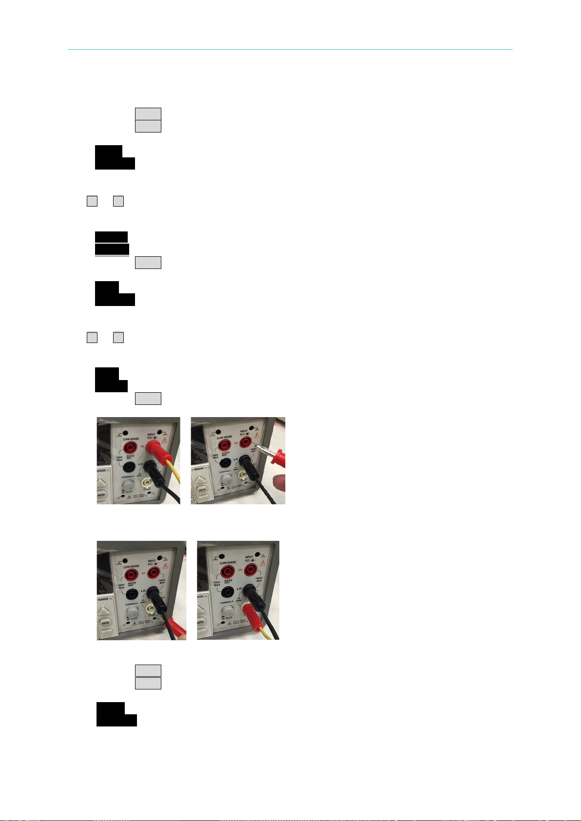
Programmable DC Power Supply 62000L Series User’s Manual
6. Rotate the knob to CAL V to calibrate output voltage, and to CAL C to calibrate output
current. Select CAL V to calibrate the output voltage.
7. Press the Menu button once to confirm. A blinking V_LO will show on the display.
8. Press the Menu button onc e to confirm. the supply starts running the LO voltage
adjustment. The display will look like the state below.
V_LO
01.800V
9. Read the DVM and adjust the voltage value on the display of the 62000L series to match
the measured value. For example, if the DVM’s reading is 2.029V, use the knob and the
or buttons to adjust the display value to 2.029V. The display will look like the state
below. For accurate calibration, you should wait for the DVM reading to stabilize for
several seconds.
V_LO
1.429V
10. Press the Menu button once to confirm. Then the supply starts running the HI voltage
adjustment. The display will look like the state below.
V_HI
34.200V
11. Read the DVM and adjus t the voltage value on the display of the 62000L series to match
the measured value. For example, if the DVM’s reading is 32.063V, use the knob and the
or buttons to adjust the display value to 32.063V. The display will look like the state
below. For accurate calibration, you should wait for the DVM reading to stabilize for
several seconds.
V_HI
33.063
12. Press the Menu button once to finish the settings.
13. Disconnect the banana jack from the INPUT HI of the DVM as the pictures shown below.
14. Plug the banana jack into the CURRENT terminal of the DVM as the pictures shown
below.
15. Rotate the knob to CAL C to calibrate output current.
16. Press the Menu button once to confirm. A blinking C_LO will show on the display.
17. Press the Menu button once to confirm. It starts running the LO current adjustment. The
display will look like the state below.
C_LO
0.3200A
18. Read the DVM and adjus t the current value on the display of the 62000L series to match
the measured value. For example, if the DVM’s reading is 0.3500A, use the knob and the
3-28
Page 61
Power Supply Operation
If you calibrate the power supply using the remote interface, you can also
pressing the Local button on the front panel.
or buttons to adjust the display value to 0.3500A. The display will look like the state
below. For accurate calibration, you should wait for the DVM reading to stabilize for
several seconds.
C_LO
0.3500A
19. Press the Menu button once t o confirm. The supply will start running the HI current
adjustment. The display will look like the state below.
C_HI
6.4000A
20. Read the DVM and adjus t the current value on the display of the 62000L series to match
the measured value. For example, if the DVM’s reading is 6.6500A, use the knob and the
or buttons to adjust the display value to 6.6500A. The display will look like the state
below. For accurate calibration, you should wait for the DVM reading to stabilize for
several seconds.
C_HI
6.6500A
21. Press the Menu button once to finish the calibration adjustment. To quit the calibration,
press any other key to exit.
abort a calibration by placing a command via the remote interface or
3.11.5 Calibration String
You can leave a string before/after the calibration is completed. Usually used this string to
record the last calibration date or the next calibration due date. The calibration string contains
max 35 characters.
To read the calibration message, you can go through it via the front panel operation and the
remote control. To save the calibration message, you have to operate via the remote control
only.
Front Panel Operation:
To get the calibration information on the 62000L series, please follow the procedures below.
1. Press the Menu button once. Rotate the knob to the CAL.
2. Press the Menu button once to confirm. Rotate the knob to STRING.
3. Press the Menu button once to confirm. The calibration information in a scrolling text will
show on the display.
4. Use the or buttons to move forwards/backwards, or stop the running information
5. Press any other button to exit.
Remote Operation:
The power supply has to be unsecured before setting the calibration string.
The calibration string is limited up to 35 characters.
CAL:STR <quoted string>
Save the calibration message. For example, use the command CAL:STR ”CAL 14-09-13“ to
store the last calibration date or the next calibration due date.
3-29
Page 62

Programmable DC Power Supply 62000L Series User’s Manual
Note
You can select the GPIB address only from the front panel.
3.12 Remote Control Settings
To operate the power supply through remote interface you must install communication car d is
necessary. For more information about programming the power supply through th e remote
control, refer to the Chapter “Remote Control Reference
3.12.1 Remote Interface Selection
The USB (Model: PWR-opt01) and GPIB + USB (Model: PWR-opt02) interfaces are optional
accessories for the power supply. When using these interfaces, you are allowed to leave both
cords on the USB’s and GPIB’s interfaces between your power supply and the computer at
the same time. You don’t need to disconnect either connection.
3.12.1.1 USB Inter f a ce
When the USB interface is used, make sure both ends of your USB cord at your power supply
and computer are well connected.
When the USB interface is connected, your computer will detect this device and require
that a VISA driver be installed. If you had the driver installed previously, there will be no
issue with the remote communication. If not, please go to the National Instruments
website to download the NI-VISA Run-Time Engine, version 4.2 or greater. After installing
the driver, the power supply will be found via the USB interface.
”.
3.12.1.2 GPIB Interface
Each device on the GPIB interface has its own unique addres s. A repeated address will cause
problems for GPIB communication. The power suppler provides 31 addresses (0 – 30) for you
to choose from. The current address will show up on the display when you go into the Menu
via the front panel. The factory default is 10.
The GPIB address is saved in non-volatile memory, and isn’t changed when the power
supply is turned off or after resetting a remote interface.
The default of the GPIB address is 10. Avoid using the address for any inst r ument on the
interface bus.
Front Panel Operation:
To check /set the GPIB address, please follow the procedures below. Please note that this
setting is available for the 62000L series unit whose GPIB card is installed.
1. Press the Menu button once. Rotate the knob to the GPIB.
2. Press the Menu button once to confirm. A blinking ADDR will show on the display.
3. Press the Menu button once to confirm. ADDR 10 (default) will show on the display.
4. Rotate the knob to the desired address (if the address 10 doesn’t meet your needs).
5. Press the Menu button once to apply the address you set. To quit the configuration, press
any other key to exit. When a new GPIB address is chosen, it will be saved in non-volatile
memory, and will not be changed when the power supply is turned off or after resetting a
3-30
Page 63

Power Supply Operation
remote interface.
GPIB Cable Limitations:
Using the GPIB cable to connect the power supply and computer, you have the following
limitations.
The total number of connections, including the computer, can not exceed 15.
The total length of all the GPIB cables used can not be more than 2 meters times the
number of connections, up to a maximum of 20 meters.
The individual GPIB cable lengths can not exceed 4 meters. Otherwise, the data
transmission might be intermittent.
GPIB connectors can not be stacked over three connector blocks. Make sure that all
connectors are completely in position and firmly secured by the screws.
3-31
Page 64

Page 65

Remote Control Reference
4. Remote Control Reference
If you are a new user of the SCPI language, please read this chapter very car ef ully before
attempting to program the power supply. Incorrectly commanding the power supply could
cause unpredictable operation of the power supply output that may damage connected
devices.
4.1 SCPI Language Summary
4.1.1 SCPI Language Introduction
SCPI is an ASCII-based instrument command language designed for test and measurement
instruments. Its commands are based on a hierarchical structure, also known as a tree
system. In this system, related commands are grouped together under a common node or
root, or formed as subsystems. There is a tree example about a port ion of the SOURce
subsystem down here
[SOURce:]
CURRent {<current>|MIN|MAX|UP|DOWN}
CURRent? [MIN|MAX]
CURRent:
TRIGgered {<current>|MIN|MAX}
TRIGgered? {MIN|MAX}
VOLTage {<voltage>|MIN|MAX|UP|DOWN}
VOLTage? [MIN|MAX]
VOLTage:
TRIGgered {<voltage>|MIN|MAX}
TRIGgered? {MIN|MAX}
4.1.2 Symbols Used in SCPI Commands
Before continue introduce the SCPI commands for 62000L series, you need to know the
following notations used for the SCPI command syntax.
Square Brackets ([]) : Indicate optional keywords or parameters, and can be omitted.
The brackets are not sent with the command string. Braces ({}) : Enclose parameters
within a command string. The braces are not sent with the command string.
Triangle Brackets (<>) : Indicate that you have to substitute a value or a code for the
enclosed parameter. For example, the SCPI command CURRent {<current>} whose
parameter is the current enclosed in triangle brackets means you have to specify a val ue
for the parameter such as 0.1A. The brackets are not sent with the command s tring.
A Vertical Bar (|) : separates one of two or more alternative parameters.
Colon (:) : Separates a command keyword from a lower-level keyword. For example,
SOURce:CURRent:TRIGgered.
Blank Space ( ) : A blank space is used to separate a parameter from a command
keyword.
Comma (,) : A comma (,) is used to separate parameters. For example, APPLy 36,3.
Semicol on (;) : A semicolon (;) is used to separate two command string and let you can
combine two commands in a command string. For example, commanding with the
4-1
Page 66

Programmable DC Power Supply 62000L Series User’s Manual
It’s vital to use a colon and a semicolon to com bine commands from
DISP:TEXT:CLE;:SOUR:CURR MIN
If you send two query commands without reading the response from the
sending the second query command.
CAUTION
CAUTION
following string VOLT MAX;CURR MAX is the same as commanding with VOLT MAX
and then CURR MAX.
different subsystems. For example, in the following command string, an
error appears if they are not used.
4.1.3 Command Format in This Manual
The format use d on SCPI commands in this manual is like below.
CURRent {<current>|MINimum|MAXimum|UP|DOWN}
The above command consisting of upper-case and lower-case letters is the basic SPCI
syntax. The upper-case letters indicate the abbreviated spelling for the command. To shorten
program lines, you may use an abbreviated form. Generally, in order to create more readable
programs, it is best to use the complete form.
For example, via the above syntax statement, CURRENT and CURR are both available forms.
But when using unqualified and fragment forms, such as CUR and CURREN, an error will be
generated.
4.1.4 MIN and MAX Parameters
For many commands, the minimum/maximum values can be substituted by a parameter
MINimum/MAXimum. For example, in the following command:
CURRent {<current>|MIN|MAX}
To set the current limit to minimum value (0A), you can use the command CURR 0 or use
CURR MIN.
4.1.5 Setting and Querying Commands
Commands can group as setting commands and querying commands. Setting commands are
used to set value or state of the device. For example, VOLT 5 will set the CV limit to 5V.
Commands that ends with character ‘?’ are querying commands and you can use these
commands to query active setting values and states of the device. For example, VOLT? is
used to query the active CV limit value. In some querying commands, you can add
MIN/MAX/DEF parameters to query the minimum/maximum/default value of the setting. For
example, VOLT? MAX will return the maximum CV limit value of the power supply.
first, and want to read the second response, you may receive some data
from the first response followed by the complete second response. To
prevent this, do not send a query command without reading the
response. If the situation can’t be prevented, send a device clear before
4-2
Page 67

Remote Control Reference
4.1.6 SCPI Command Terminators
A command string sent to the power supply has to end wit h a <new line> character. The
message from t he IEEE-488 EOI (end-or-identify) is analyzed as a <new line> character and
used to terminate a command string substituting a <new line> character. It’s also accepted
that a <carriage return> is followed by a <new line>. Command string termination alwa ys
reset the current SCPI command path to the root level. Generally, the <new line> char acter
has the ASCII decimal code of 10.
4.1.7 Common SCPI Commands
The GPIB (IEEE-488.2 standard) defines a set of common commands performing functions
like reset, self-test, and status operations. GPIB commands always start with an asterisk “*”,
consisting of four to five characters in length, and may include one or more parameters. The
command keyword is separated from the first parameter by a blank space. You can use a
semicolon “;” to separate multiple commands as shown below:
*RST; *CLS; *ESE 32; *OPC?
4.1.8 SCPI Parameter Types
The SCPI language defines several different data formats in order to be used in program
messages and response messages. Generally, these parameters are in numeric, discrete,
Boolean, and string.
Numeric Parameters:
Number-required commands accept commonly used decimal representations of numbers
such as decimal points and scientific notation. Some special numeric parameters like
MINimum, MAXimum, and DEFault are also accepted, as well as sending engineering unit
suffixes (V, A, or S) with numeric parameters. If you leave acceptable numeric values, the
power supply will round the input numeric parameters automatically. For example:
VOLT {<voltage>|MIN|MAX|UP|DOWN}
Discrete Parameters:
You can use discrete parameters to pro gram settings that have a limited number o f values like
BUS and IMM. When querying, responses will return the short form in all upper-case letters
invariably. For example:
TRIG:SOUR {BUS|IMM}
Boolean Parameters:
You can use Boolean parameters to represent a single binary condition that is either true or
false. If it’s a f alse c ondition, the power supply will accept OFF or 0. If it’s a true condition, the
power supply will accept ON or 1. When querying a Boolean setting, the power supply will
return 0 or 1 invariably. For example:
DISP {OFF|ON}
String Parameters:
4-3
Page 68

Programmable DC Power Supply 62000L Series User’s Manual
String parameters contain virtually any set of ASCII characters. A string has to start and end
with matching quotes; either with a single quote or with a double quote. You can type it twice
without any characters in between to include the quote delimiter as part of the string. For
example:
DISP:TEXT <quoted string>
4.2 SCPI Commands
This section collects the commands and provides the descriptions about output setting &
operation, triggering, system, calibration, status, and IEEE-488 conformance.
4.2.1 Output Settings and Operation Commands
This section provides commands to program the power supply output operation. Although the
APPLy command leaves the most straightforward way to program the CV/CC limit settings,
the VOLT and CURR commands give more flexibility to change the individual settings.
APPLy {<voltage>|DEF|MIN|MAX}[,{<current>|DEF|MIN|MAX}]
APPLy?
[SOURce:]
CURRent[:LEVel][:IMMediate][:AMPLitude]
CURRent[:LEVel][:IMMediate][:AMPLitude]? {MIN|MAX}
CURRent[:LEVel][:IMMediate]:STEP[:INCRement]
CURRent[:LEVel][:IMMediate]:STEP[:INCRement]? {DEF}
CURRent[:LEVel]:TRIGgered[:AMPLitude] {<current>|MIN|MAX}
CURRent[:LEVel]:TRIGgered[:AMPLitude]? {MIN|MAX}
CURRent:PROTection[:LEVel] {<current>|MIN|MAX}
CURRent:PROTection[:LEVel]? {MIN|MAX}
CURRent:PROTection:STATe {0| 1|OFF|ON}
CURRent:PROTection:STATe?
CURRent:PROTection:TRIPped?
CURRent:PROTection:CLEar
VOLTage[:LEVel][:IMMediate][:AMPLitude] {<voltage>|MIN|MAX}
VOLTage[:LEVel][:IMMediate][:AMPLitude]? {MIN|MAX}
VOLTage[:LEVel]:TRIGgere d [:AMPLitude] {<voltage>|MIN|MAX}
VOLTage[:LEVel]:TRIGgered[:AMPLitude]? {MIN|MAX}
VOLTage:PROTection[:LEVel] {<voltage>|MIN|MAX}
VOLTage:PROTection[:LEVel]? {MIN|MAX}
VOLTage:PROTection:STATe {0| 1|OFF|ON}
VOLTage:PROTection:STATe?
VOLTage:PROTection:TRIPped?
VOLTage:PROTection:CLEar
MEASure
:CURRent[:DC]?
[:VOLTage][:DC]?
:SENSe:EXTernal {OFF|ON}
:SENSe:EXTernal?
OUTPut
[:STATe] {0|1|OFF|ON}
[:STATe]?
{<current>|MIN|MAX}
{<current>|DEF}
4-4
Page 69

Remote Control Reference
For a clearer command description, please read the following examples carefully.
APPLy {<voltage>|DEF|MIN|MAX}[,{<current>|DEF|MIN|MAX}]
This command is used to set the CV/CC li mit values. I t is combination o f the co mmands VOL T
and CURR. If one of the voltage and current value are not in the valid data range, an error
occurs. The CV/CC limit values changes as soon as the command is executed.
Instead of entering voltage/current value, the parameters DEF/MIM/MAX are also acceptable.
MINimum and MAXimum set the voltage or current to the minimum and maximum available
value of the CC/CV limit levels. If a DEFault parameter is used, the CV/CC limit level stored in
the location 0 will be set.
If there is only one parameter following the APPLy command, the power s upply will use it to
set the CV limit.
APPLy?
This command is used to query the active applied CV/CC limit value. The CV/CC limit values
will return in the scientific format and separated by a comma.
OUTPut {OFF|ON}
This command is used to enable or disable the output of the power s upply. Aft er reset, the
output is always turned OFF.
OUTPut?
This query command is used to query the ou tput state. If the output is turned ON, 1 is returned .
If the output is turned OFF, 0is returned.
CURRent {<current>|MINimum|MAXimum|UP|DOWN}
This command is used to set the CC limit level of the power supply. If the output is turn ON,
this commands change the output of the power supply to the newly programmed CC limit
level.
The MINimum or MAXimum can be substituted for a specific value used on current. The
predetermined UP or DOWN parameter can be used to increase or decrease one step of the
CC limit level. The command CURRent:STEP describe below is used to set the amount of
increment and decrement step.
CURRent? {MINimum|MAXimum}
This query command is used to return the presently programmed current level of the power
supply. The presently programmed current level will return in scientific format. When
commanding CURR? MAX and CURR? MIN, the highest and lowest programmable current
levels return.
CURRent:STEP {<numeric value>|DEFault}
This command is used to set the step size that used to increase or decreas e t he CC limit
value with CURR command describe above. The default step is 5mA.
CURRent:STEP? {DEFault}
This query command is used to query the active current step. The active current step value
will return in scientific format.
CURRent:TRIGgered {<current>|MINimum|MAXimum}
4-5
Page 70

Programmable DC Power Supply 62000L Series User’s Manual
This command is used to program the pending triggered current level, which is a stored value
that is transferred to the output terminals when a trigger occurs. Subsequent CURRent
commands won’t affect any pending triggered levels.
CURRent:TRIGgered? [MINimum|MAXimum]
This query command is used to query the triggered current level presently programmed.
When commanding CURR:TRIG? MAX and CURR:TRIG? MIN, the power supply returns the
highest and lowest programmable triggered current levels.
CURRent:PROTection {<current>|MINimum|MAXimum}
This command is used to set the current level where the overcurrent protection (OCP) circuit
will trip. If the output current is greater than the OCP level, the output current will be
programmed to zero. Then the Questionable Status register “OCP” bit will be set as well. This
condition can be cleared by commanding CURR:PROT:CLE after the condition caused the
OCP trip is removed.
CURRent:PROTection? {MINimum|MAXimum}
This query command is used to query the overcurrent protection trip level presently
programmed. When commanding CURR:PROT? MAX and CURR:PROT? MIN, the power
supply returns the maximum and minimum programmable overcurrent trip levels.
CURRent:PROTection:STATe {0|1|OFF|ON}
This command is used to enable or disable the overcurrent protection function.
CURRent:PROTection:STATe?
This query command is used to return the state of the overcurrent protection function. If the
OCP is enabled, 1 is returned. Otherwise 0 is returned.
CURRent:PROTecton:TRIPped?
This query command is used to query if a OCP tripped event occ urred. If there is no OCP
tripped event occurred, 0 is returned. Otherwise 1 is returned. To clear OCP tripped event,
use the CURRent:PROTection:CLEar command.
CURRent:PROTection:CLEar
This command is used to clear the overcurrent protection tripped event. After commanding,
the output current is restored to the state in which it was before the current protection tripped
and the OCP trip level keeps unchanged to the value presently programmed. Before clearing
the tripped event, keep the output current lower than the trip OCP point, or adjust the OCP trip
level to be greater than the output setting.
MEASure:CURRent?
This command is used to query the current output value measured by the power supply. The
reading value is returned in the scientific format.
VOLTage {<voltage>|MINimum|MAXimum|UP|DOWN}
This command is used to set the CV limit level of the power supply. If the output is turn ON,
this commands change the output of the power supply to the newly programmed CV limit
level.
The MINimum or MAXimum can be substituted for a specific value used on current. The
predetermined UP or DOWN parameter can be used to increase or decrease one step of the
CV limit level. The command VOLTage:STEP describe below is used to set the amount of
increment and decrement step.
VOLTage? [MINimum|MAXimum]
4-6
Page 71

Remote Control Reference
This query command is used to query the presently programmed voltage level of the power
supply. The presently programmed voltage level will return in scientific format. When
commanding VOLTage? MAX and VOLTage? MIN, the highest and lowest programmable
voltage levels return.
VOLTage:STEP {<numeric value>|DEFault}
This command is used to set the step size that used to increase or decreas e t he CV limit
value with VOLT command describe above. The default step is 5mV.
VOLTage:STEP? {DEFault}
This query command is used to query the active voltage step. The active voltage step value
will return in scientific format.
CURRent:TRIGgered {<current>|MINimum|MAXimum}
This command is used to program the pending triggered current level, which is a stored value
that is transferred to the output terminals when a trigger occurs. Subsequent CURRent
commands won’t affect any pending triggered
VOLTage:TRIGgered {<voltage>|MINimum|MAXimum}
This command is used to program the pending triggered voltage level, which is a stored value
that is transferred to the output terminals when a trigger occurs. Subsequent VOLTage
commands won’t affect any pending triggered levels.
VOLTage:TRIGgered? [MINimum|MAXimum]
This query command is used to query the triggered voltage level presently programmed.
When commanding VOLT:TRIG? MAX and VOLT:TRIG? MIN, the power supply returns the
highest and lowest programmable triggered voltage levels.
VOLTaget:PROTection {<voltage>|MINimum|MAXimum}
This command is used to set the voltage level where the overvoltage protection (OVP) circuit
will trip. If the output voltage is greater than the OVP level, an int er nal SCR will shorten the
output. Then the Questionable Status register “OVP” bit will be set as well. This condition can
be cleared by commanding VOLT:PROT:CLE after the condition caused the OVP trip is
removed.
VOLTage:PROTection? {MINimum|MAXimum}
This query command is used to return the overvoltage protection trip level presently
programmed. When commanding VOLT:PROT? MAX and VOLT:PROT? MIN, the power
supply returns the maximum and minimum programmable overvoltage trip levels.
VOLTage:PROTection:STATe {0|1|OFF|ON}
This command is used to enable or disable the overvoltage protection function.
VOLTage:PROTection:STATe?
This query command is used to return the state of the overvoltage protection function. If the
OVP is enabled, 1 is returned. Otherwise 0 is returned.
VOLTaget:PROTecton:TRIPped?
This query command is used to query if a OVP tripped event occurred. If there is no OVP
tripped event occurred, 0 is returned. Otherwise 1 is returned. To clear OVP tripped event,
use the VOLTage:PROTection:CLEar command.
VOLTage:PROTection:CLEar
4-7
Page 72

Programmable DC Power Supply 62000L Series User’s Manual
Note
The time delay is feasible for the bus trigger source only.
This command is used to clear the overvoltage protection tripped event. After commanding,
the output voltage is restored to the state in which it was before the protection feature
occurred and the OVP trip level keeps unchanged to the value pr es ent ly programmed. Before
clearing the tripped event, keep the output voltage lower than the trip OVP point, or adjust the
OVP trip level more greatly than the output setting.
MEASure[:VOLTage]?
This command is used to query the voltage output value measured by the power supply. The
reading value is returned in the scientific format.
4.2.2 Tri ggering Commands
The power supply under the triggering system allows a change in voltage and c urrent when
receiving a trigger. In addition, it also allows to you to select a trigger source, and to insert a
trigger. To trigger the power supply, you need to finish the following multi-step process.
First of all, you have to specify the source from which the power supply wil l acc ept the
trigger. A bus (software) trigger or an immediat e trigger from the remote interface is
acceptable.
After that, the time delay between the detection of the trigger on the specified trigger
source and the start of any corresponding output change is available to be set.
At last, you have to provide an INITiate command. If selecting the IMMediate source, the
selected output will be set to the triggered level right away. However, if the trigger source
is the bus, your power supply will be set to the triggered level after receiving GET (the
Group Execute Trigger) or *TRG command.
The following commands are collected and used to deal with triggering. For more detailed
description, please check from the section 4.2.2.1 and 4.2.2.2
INITiate[:IMMediate]
TRIGger[:SEQuence]
:DELay {<seconds>|MIN|MAX}
:DELay?
:SOURce {BUS|IMM}
:SOURce?
*TRG
.
4.2.2.1 Trigger Source Opti ons
You have to specify the source from w hich the power supply will accept the trigger. In addition,
the trigger is stored in volatile memory. And the source is set to bus after powering on the
power supply or resetting a remote interface.
Bus Triggering:
Send TRIG:SOUR BUS to select the bus trigger source.
Send *TRG to trigger the power supply via the remote interface, such as USB or GPIB
after selecting the bus source. When sending this command, the trigger acts after the
specified time delay if any delay is given.
4-8
Page 73

Remote Control Reference
Send a wait command *WAI to ensure synchronization once the bus source is selected.
When commanding *WAI, the power supply will wait for all pending operations to finish
before executing other additional commands. For example, the command, TRIG:SOUR
BUS; *TRG; *WAI; *TRG; *WA I guarantees that the first trigger is accepted and will be
executed before the second trigger is recognized.
Use the operation complete query (*OPC?) or the operation complete (*OPC) command
to generate signal when the last operation is finished. Commanding *OPC? will return 1 to
the output buffer when the last operation is finished. Commanding *OPC will set the OPC
bit 0 in the Standard Event register when the operation is finished.
Immediate Triggering:
Send TRIG:SOUR IMM to select the immediate trigger source.
After selecting IMMediate as a trigger source, INITiate immediately transfers the
VOLT:TRIG or CURR:TRIG value to the VOLT or CURR value. All delay will be ignored.
4.2.2.2 Triggering Command Des cription
For new users, please read the command description carefully before commanding.
Incorrectly commanding the supply will result in no reaction.
INITiate
If the trigger source is IMMEDIATE, this comman d complete one full trigger cycle. If the t rigger
source is BUS, this command initiates the trigger system.
TRIGger:DELay {<seconds>|MINimum|MAXimum}
This command is used to set the time delay between the detection of an event on the
specified trigger source and the start of any c orresponding trigger action on the output. Select
from 0 to 3600 seconds, i.e. MIN = 0 seconds, and MAX = 3600 seconds. At *RST, the value
is set to 0 seconds.
TRIGger:DELay? [MINimum|MAXimum]
This query command is used to query the trigger delay.
TRIGger:SOURce {BUS|IMMediate}
This command is used to select the trigger source of the power supply. Either a bus trigger or
an internal immediate trigger will be accepted. At *RST, the bus trigger source is selected.
TRIGger:SOURce?
This query command is used to query the present trigger source, such as BUS or IMM.
*TRG
This command is used to generate a trigger to the trigger subsystem that has selected a bus
trigger as its source.
4.2.3 Output Control Commands
This section provides information about commands for multiple output control and output
sequence.
4-9
Page 74

Programmable DC Power Supply 62000L Series User’s Manual
4.2.3.1 Commands for Master & Slave Application
The commands in this section are used to control the Master & Slave appli cation. For more
details about Master & Slave application, please refer to the section 3.7
OUTPut:
:CONTrol:DELay {<on delay>|MIN|MAX},{<off delay>|MIN|MAX}
:CONTrol:DELay?
:CONTrol:MODE {0|1|2|3|4|5}
:CONTrol:MODE?
:CONTrol[:STATe] {0|1|OFF|ON}
:CONTrol[:STATe]?
OUTPut:CONTrol:DELay {<on delay>|MIN|MAX},{<off delay>|MIN|MAX}
This command is used to set the turn-on delay and turn-off delay of the master-slave control.
The available value is 0~60s.
OUTPut:CONTrol:DELay?
This command is used to query the turn-on and turn-off delay of the master-slave control. The
turn-on delay and the turn-off delay returns and separated by a comma. For example, the
returned “+3,+5” is indicate the turn-on delay is 3 seconds and the tu rn-off del ay i s 5 seconds.
OUTPut:CONTrol:MODE {0|1|2|3|4|5}
This command is used to set the operation mode of the master-slave control.
0 is the P-MA (parallel master) mode. 1 is the P -SL (parallel slave) mode. 2 is the S-M A (se ri al
master) mode. 3 is the S-SL (serial slave) mode. 4 is the NORMAL m ode. And 5 is the
TRACK mode.
OUTPut:CONTrol:MODE?
This command is used to query the operation mode of the master-slave control.
OUTPut:CONTrol[:STATe] {0|1|OFF|ON}
This command is used to enable/disable the master-slave control function.
OUTPut:CONTrol[:STATe]?
This command is used to query the ON/OFF state of the mas ter-slave control function. If the
master-slave control is enabled, 1 is returned. Otherwise, 0 is returned.
.
4.2.3.2 Commands for Output Se que nce
The commands in this section are used to control output sequence. For more details about
output sequence control, please refer to section 3.9
OUTPut:
:SEQuence[:STATe] {0|1|OFF|ON}
:SEQuence[:STATe]?
:SEQuence:MODE {0|1|2}
:SEQuence:MODE?
:SEQuence:CYCLe {<cycle>}
:SEQuence:CYCLe?
:SEQuence:SETup {<start step>},{<stop step>}
:SEQuence:SETup?
:SEQuence:STEP:CURRent {<step>},{<current>|DEF|MIN|MAX}
4-10
.
Page 75

Remote Control Reference
:SEQuence:STEP:CURRent? {<step>}
:SEQuence:STEP:DWELl {<step>},{<time in ms>|MIN|MAX}
:SEQuence:STEP:DWELl? {<step>}
:SEQuence:STEP:RAMP {<step>},{<time in ms>|MIN|MAX}
:SEQuence:STEP:RAMP? {<step>}
:SEQuence:STEP:VOLTage {<step>},{<voltage>|DEF|MIN|MAX}
:SEQuence:STEP:VOLTage? {<step>}
:SEQuence:STEP? {<step>}
OUTPut:SEQuence[:STATe] {0|1|OFF|ON}
Enable/Disable output sequence function.
OUTPut:SEQuence[:STATe]?
Return 0 if output sequence is disabled, and return 1 if output sequence is enabled.
OUTPut:SEQuence:MODE {0|1|2}
Set mode of output sequence. 0 is voltage only. 1 is current only. 2 is both voltage and current
are controlled by the output sequence.
OUTPut:SEQuence:MODE?
Query sequence mode. Return 0, 1 or 2.
OUTPut:SEQuence:CYCLe {<cycle>}
Set output sequence repeat cycle. The value of cycle is 0~65535. 0 means always repeat.
OUTPut:SEQuence:CYCLe?
Query output sequence repeat cycle.
OUTPut:SEQuence:SETup {<start step>},{<stop step>}
Set start step and stop step of output sequence. Step is S0~S7.
OUTPut:SEQuence:SETup?
Query start step and stop step.
OUTPut:SEQuence:STEP:VOLTage
Set voltage of a step. Step is S0~S7.
OUTPut:SEQuence:STEP:VOLTage? {<step>}
Query voltage setup of a step. Step is S0~S7. Return voltage in Volts.
OUTPut:SEQ uence: STEP:C URRent {< step>},{<current>|DEF|MIN|MAX}
Set current of a step. St ep is S0~S 7.
OUTPut:SEQuence:STEP:CURRent? {<step>}
Query current setup of a step. Step is S0 ~S7. Return current in amp s.
OUTPut:SEQuence:STEP:RAMP {<step>},{<time in ms>|MIN|MAX}
Set ramp time of a step. St ep is S0~S 7. The ramp time allows you to set from 0 to
3599999ms.
OUTPut:SEQuence:STEP:RAMP? {<step>}
Query ramp tim e of a step. Step is S0~S7. Return ramp time in ms.
OUTPut:SEQuence:STEP:DWELI {<step>},{<time in ms>|MIN|MAX}
{<step>},{<voltage>|DEF|MIN|MAX}
4-11
Page 76

Programmable DC Power Supply 62000L Series User’s Manual
Set dwelling of a s tep. The step index is from S0 to S7. Maximum dwelling is 86399999ms.
OUTPut:SEQuence:STEP:DWELI? {<step>}
Query dwelling of a step. The step index is from is S0 to S7. Return dwelling in ms.
OUTPut:SEQuence:STEP? {<step>}
Query a step setting. Step is S0~S 7.
4.2.4 System-Related Commands
The following system-related commands are used to display the power supply’s status. For
detailed command information, please read the command descriptions coming next to the
commands.
DISPlay[:WINDow]
[:STATe] {OFF|ON}
[:STATe]?
:TEXT[:DATA] <quoted string>
:TEXT[:DATA]?
:TEXT:CLEar
SYSTem
:BEEPer[:IMMediate]
:BEEPer:ALARm:OVP[:STATe] {0|1|OFF|ON}
:BEEPer:ALARm:OVP[:STATe]?
:BEEPer:ALARm:OCP[:STATe] {0|1|OFF |ON}
:BEEPer:ALARm:OCP[:STATe]?
:BEEPer:NORMal[:STATe] {0|1|OFF |ON}
:BEEPer:NORMal[:STATe]?
:ERRor?
:VERSion?
*IDN?
*RST
*TST?
*SAV {0|1|2|3}
*RCL {0|1|2|3}
DISPLay {OFF|ON}
This command is used to turn the front-panel display off or on. When turning off the display,
the display will show nothing, but ERR annunciator. After returning to the local mode by
pressing LOCAL key on the front panel, the display will be turned on automatically.
DISPlay?
This query command is used to query the display ON/OFF status. If 0 is returned, it means the
display is under OFF status. If 1 is returned, it means the display is under ON status.
DISPlay:TEXT <quoted string>
This command is used to set a string to display on the f r ont panel. Once the command is
executed, the front panel display will be turned OFF, and the string will be shown on the
display. The string to set can only contain up to 49 alphanumeric characters and must in
enclosed quotes. The string will scroll on the display if it is longer than 6 char acters. ALL
letters displaying on the display will replace with uppercase ones and characters that can not
4-12
Page 77

Remote Control Reference
display will replace with blank spaces. After turning the display ON, the string will not s how
anymore.
DISPlay: TEXT?
This query command is used to query the string set to display on the front panel screen.
DISPlay:TEXT:CLEar
This command is used to clear the message shown on the front panel.
SYSTem:BEEPer
This command is used to issue a single beep instantly.
SYSTem:ERRor?
This command is used to get an error that queued in the power supply’s error queue. If there’s
no errors in the error queue, a message “+0,No errors” will return. For more detail please refer
to “Error States
”
SYSTem:VERSion?
This query command is used to query the SCPI version used in the power supply. The
retrieved value is a string in the form of YYYY.V where Y stands for the year of the version,
and V stands for a version number for that year (for example, 1996.0).
*IDN?
This query command is used to query the identification string of the power supply. The
identification string contains 4 fields like that are shown below.
CHROMA ATE,62010L-36-7,L01000000066,1.00-1.00
The first field is the manufacturer name. The second field is the model name. The third field is
the serial number of the device. And the last field is the firmware versions of the main MCU
and communication card.
*RST
This command is used to set the power supply to its power on s t ate.
The CV/CC limits are reset to the values that stored in the location 0.
The OVP/OCP trip levels and ON/OFF states are reset to the values that stored in the
location 0.
BUS is selected as the trigger source.
The voltage/current trigger level are set to 0V and 1A.
Trigger delay of the voltage/current is set to 0s.
The voltage and current step are reset to default values, 5mV and 5mA.
The display is turned ON.
*TST?
This command is used to request a sel f-test and w il l return the result of the test. If the self-test
is passed, 0 is returned. If the test if failed, 1 is returned. One or more errors will also be
generated if the self-test is failed.
*SAV {0|1|…|15}
This command is used to save the present ope ration states to the non-volatil e memory. Select
the location 0~15 to store the operation states to. The operation states that stored in the
location 0 will set as power-on settings. For more details, please refer to the “Storing and
Recalling Operation States”.
4-13
Page 78

Programmable DC Power Supply 62000L Series User’s Manual
*RCL {0|1|…|15}
This command is used to recall the stored operation states. For more details, please refer to
the “Storing and Recalling Operation States”.
4.2.5 Cal ibra ti on Co mma nds
The following calibration commands are used to calibrate your power supply. For detailed
command information, please read the command descriptions coming next to the commands.
CALibration
:COUNt?
:CURRent[:DATA] <numeric value>
:CURRent:LEVel {MIN|MAX}
:SECure:STATe {OFF|ON},<code>
:STRing <string>
:STRing?
:VOLTage[:DATA] <numeric value>
:VOLTage:LEVel {MIN|MA X}
CALibration:COUNTt?
This query command is used to return the number of time that it has been calibrated.
CALibration:CURRent[:DATA] <numeric value>
This command is used to enter the CC calibration data. Before using this command, a
calibration level should set first or an calibration sequence interrupt error will be generated.
CALibration:CURRent:LEVel [MINimum|MAXimum]
This command is used to set the CC calibration level of the power supply. T here are two
calibration points for the power supply to calibrate CC. The MIN level must be calibrated first
or a calibration sequence interrupt error will be generated.
CALibration:SECure:CODE < code>
This command is used to change the security code. To change the security c ode, you must
un-secure the calibration first and secure the calibration again with the new code after
entering the new security code with this command. The code is an un-quoted string wit h 6
alphanumeric characters. No matter the uppercase or lowercase letters.
CALibration:SECure:STATe {OFF|ON},<code>
This command is used to enable/disable the calibration security of the power supply. The
code is an un-quoted string with 6 alphanumeric characters. No matter the uppercase or
lowercase letters.
CALibration:SECure:STATe?
This command is used to query the calibration security state of the power supply. If the
security is enabled, 1 is return. If the security is disabled, 0 is return.
CALibration:STRing <quoted string>
This command is used to write a message about the calibration. For example, you can use
this command to save the calibration date. The string can contains up to 35 alphanumeric
characters and must in an enclosed quote.
CALibration:STRing?
This command is used to query the calibration string.
4-14
Page 79

Remote Control Reference
CALibration:VOLTage[:DATA] <numeric value>
This command is used to enter the CV calibration data. Before using this command, a
calibration level should set first or an calibration sequence interrupt error will be generated.
CALibration:VOLTage:LEVel {MINimum|MIDdle|MAXimum}
This command is used to set the CV calibration level of the power supply. There are two
calibration points for the power supply to calibrate CV. The MIN level must be calibrate first or
an calibration sequence interrupt error will be generated.
4.2.6 Status Reporting Commands
The following commands are used to report event statuses, cleaning statuses, and set/enable
bits in specific events. For detailed command information, please read the command
descriptions coming next to the commands.
STATus
:QUEStionable:CONDition?
:QUEStionable:ENABle <enable value>
:QUEStionable:ENABle?
:QUEStionable[:EVENt?]
*CLS
*ESE <enable value>
*ESE?
*ESR?
*OPC
*OPC?
*PSC {0|1}
*PSC?
*SRE <enable value>
*SRE?
*STB?
*WAI
STATus:QUEStionable:CONDition?
This command is used to query the operation mode of the power s upply. If 0 is returned, the
power supply is output off or the output is un-regulation. If 1 is returned, the power supply in
under CC mode. If 2 is returned, the power supply is under CV mode. If 3 is returned, the
power supply is under CP mode.
STATus:QUEStionable?
This command is used to query Questionable Status Event register. A decimal value is
returned, and conforms to the binary-weighted sum of all bits in the register. These bits are
locked. Reading the event register can clear it.
STATus:QUEStionable:ENABle <enable value>
This command is used to set the Questionable Status Enable register. Then the
corresponding bits in the Questionable Status Event register are enabled to report to the
Status Byte.
STATus:QUEStionable:ENABle?
This command is used to query the Questionable Status Enable register. Then the power
supply will return a binary-weighted decimal representing the bits set in the enable register.
4-15
Page 80

Programmable DC Power Supply 62000L Series User’s Manual
*CLS
This command is used to clear all event registers and Status Byte register.
*ESE <enable value>
This command is used to enable bi ts in the S tandard Event Enabl e re gister. Then the selected
bits will be reported to the Status Byte.
*ESE?
This command is used to query the Standard Event Enable register. Then the power supply
will return a decimal value which conforms to the binary-weighted sum of all bits in the
register.
*ESR?
This command is used to query the Standard Ev ent register. Then the power supply w ill return
a decimal value which conforms to the binary-weighted sum of all bits in the r egister.
*OPC
After this command is executed, the “OPC” bit, bit 0 of the Standard Event register, is set to
1..
*OPC?
After the command is executed, 1 is returned.
*PSC {0|1}
Enable/Disable power-on status clear function. By default, the PSC is enabled and the
Status Byte enable register and the Standard Event enable register are cleared while t he
power supply is power on. Use command *PSC 0 to prevent the registers from been cleared
while power on.
*PSC?
This query command is used to query the power-on status clear setting. If PSC is enabled,
return 1. Otherwise return 0..
*SRE <enable value>
This command is used to set the Status Byte Enable register.
*SRE?
This command is used to query the Status Byte Enable register. Then the power supply will
return a binary-weighted decimal representing the bits set in the enable register.
*STB?
This command is used to query the Status Byte summary register. *STB? Is similar to a serial
poll, but its process is like any instrument command. Using this command w il l return the same
result as a serial poll, but the Request Service bit (bit 6) won’t be cleared if a serial poll has
occurred.
*WAI
This command is used to instruct the power supply to wait for all pending oper at ions done
before executing additional commands over the remote interface. It’s used only in the
triggered mode.
4-16
Page 81

Remote Control Reference
4.2.7 IEEE-488 Conformance Information
The following commands are used to command IEEE-488. Since most of them are described
above, limited information about the definitions of the dedicated hardware lines and
addressed commands are listed here.
*CLS
*ESE <enable value>
*ESE?
*ESR?
*IDN?
*OPC
*OPC?
*PSC {0|1}
*PSC?
*RST
*RCL <recall index>
*SAV <store index>
*SRE <enable value>
*SRE?
*STB?
*TRG
*TST
Dedicated Hardware Lines:
ATN – Attention
IFC – Interface Clear
REN – Remote Enable
SRQ – Service Request Enable
Addressed Commands:
DCL – Device Clear
EOI – End or Identify
GET – Group Execute Trigger
GTL – Go to Local
LLO – Local Lockout
SDC – Selected Device Clear
SPD – Serial Poll Disable
SPE – Serial Poll Enable
4.3 Programming Overview
This section provides an overview of the basic techniques used to program the power supply
over the remote interface.
4.3.1 Regarding Programming Ranges
62000L series is a power supply with the auto range feature. You don’t have to set values
depending on the range. The available programming value for a parameter var ies ac cor ding
to the desired output range of the power supply. Please refer to the following table to identify
the programming values.
4-17
Page 82
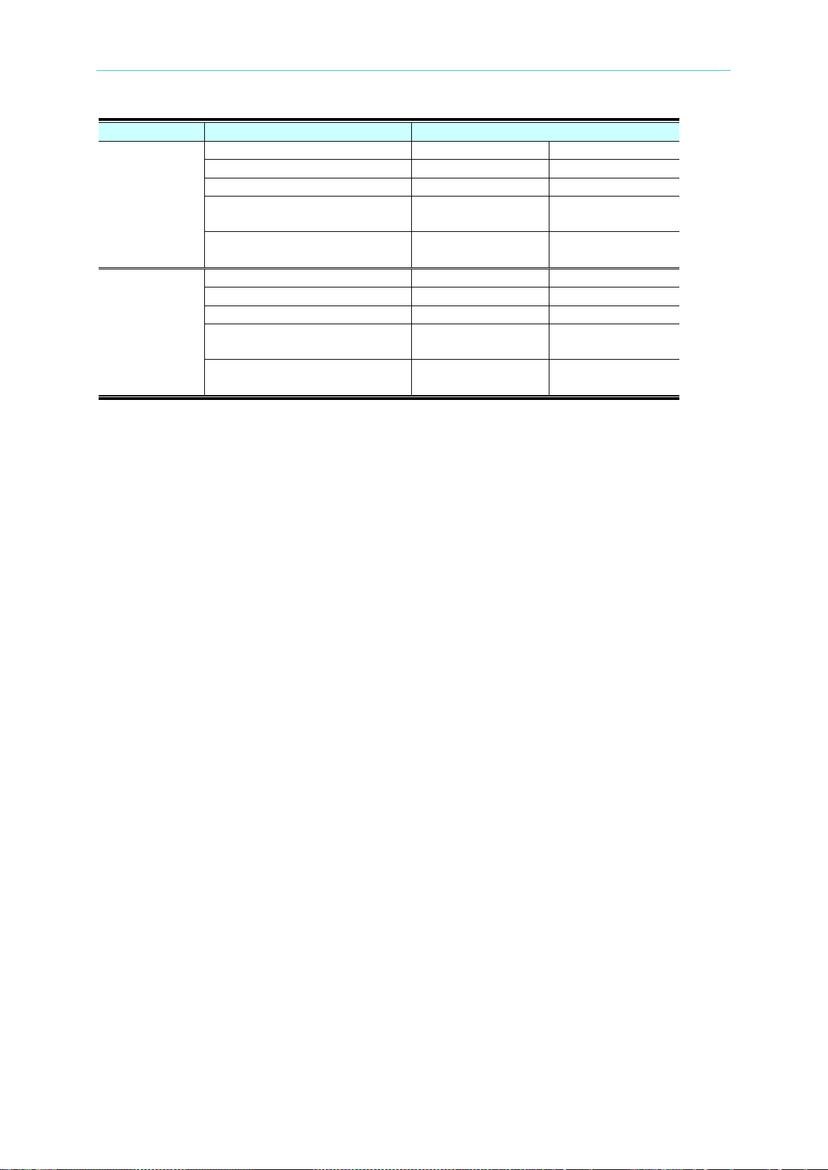
Programmable DC Power Supply 62000L Series User’s Manual
Source
Item
Value Info. (62010L-36-7/62015L-60-6)
Programming Range
0V to 37.8V
0V to 60V
MAX Value
37.8V
60V
MIN Value
0V
0V
DEFault Value
Value stored in
location 0
Value stored in
location 0
*RST Value
Value stored in
location 0
Value stored in
location 0
Programming Range
0A to 7.35A
0A to 6A
MAX Value
7.35A
6A
MIN Value
0A
0A
DEFault Value
Value stored in
location 0
Value stored in
location 0
*RST Value
Value stored in
location 0
Value stored in
location 0
Voltage
Current
4.3.2 Regarding SCPI Status Registers
All SCPI devices utilize st atus registers in the same way. The status system can record
different kinds of condition groups, such as the Status Byte register, the Standard Event
register, and the Questionable Status register. For example, the Status Byte register records
high-level summary information which is reported in the other register groups. The following
diagram illustrates the SCPI status system used by the power supply.
4-18
Page 83
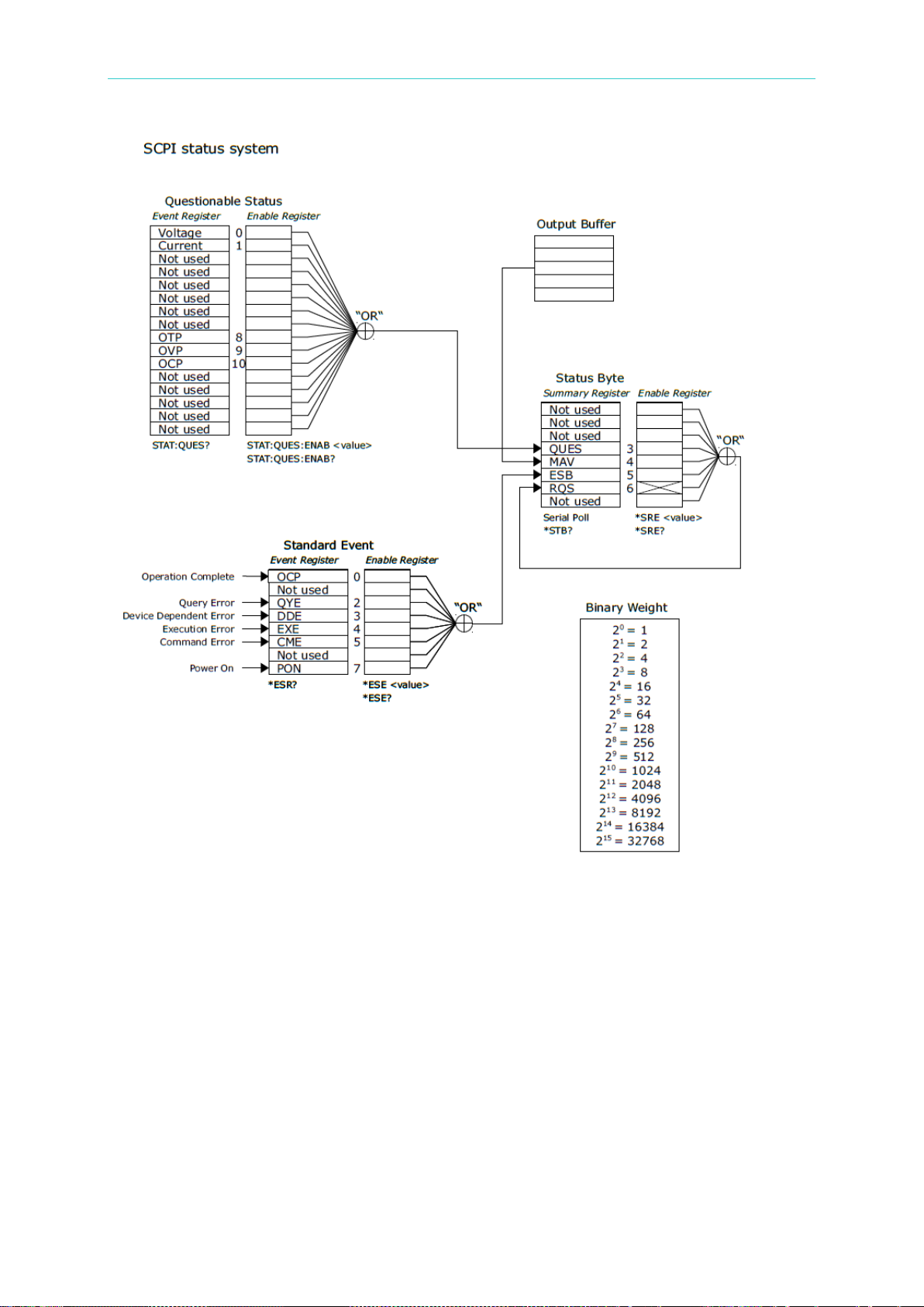
Remote Control Reference
In addition, an event register is a read-only register that can generate defined conditions from
the power supply. Bits in an event register are under a locked status. Once an even bit is set,
the following status changes will be ignored. Bits in an event register are automatically
cleared by a query, such as *ESR?, STAT:QUES:EVEN? or *CLS. But sending *RST or
device clear won’t clear bits in event registers. Querying an event register will return a deci mal
value which conforms to the binary-weighted sum of all bits set in the register.
On the other hand, an enable register can define w hich bits in the cor responding even register
are ORed logically to form a single summary bit. Enable registers is able to read and write.
When querying an enable register, it won’t be cleared. Using *CLS can’t clear enable
registers, but it will clear the bits in the event registers. To enable bits in an enable register,
you have to write a decimal value which conforms to the binary-weighted sum of the bits that
you prefer enable in the register.
4-19
Page 84
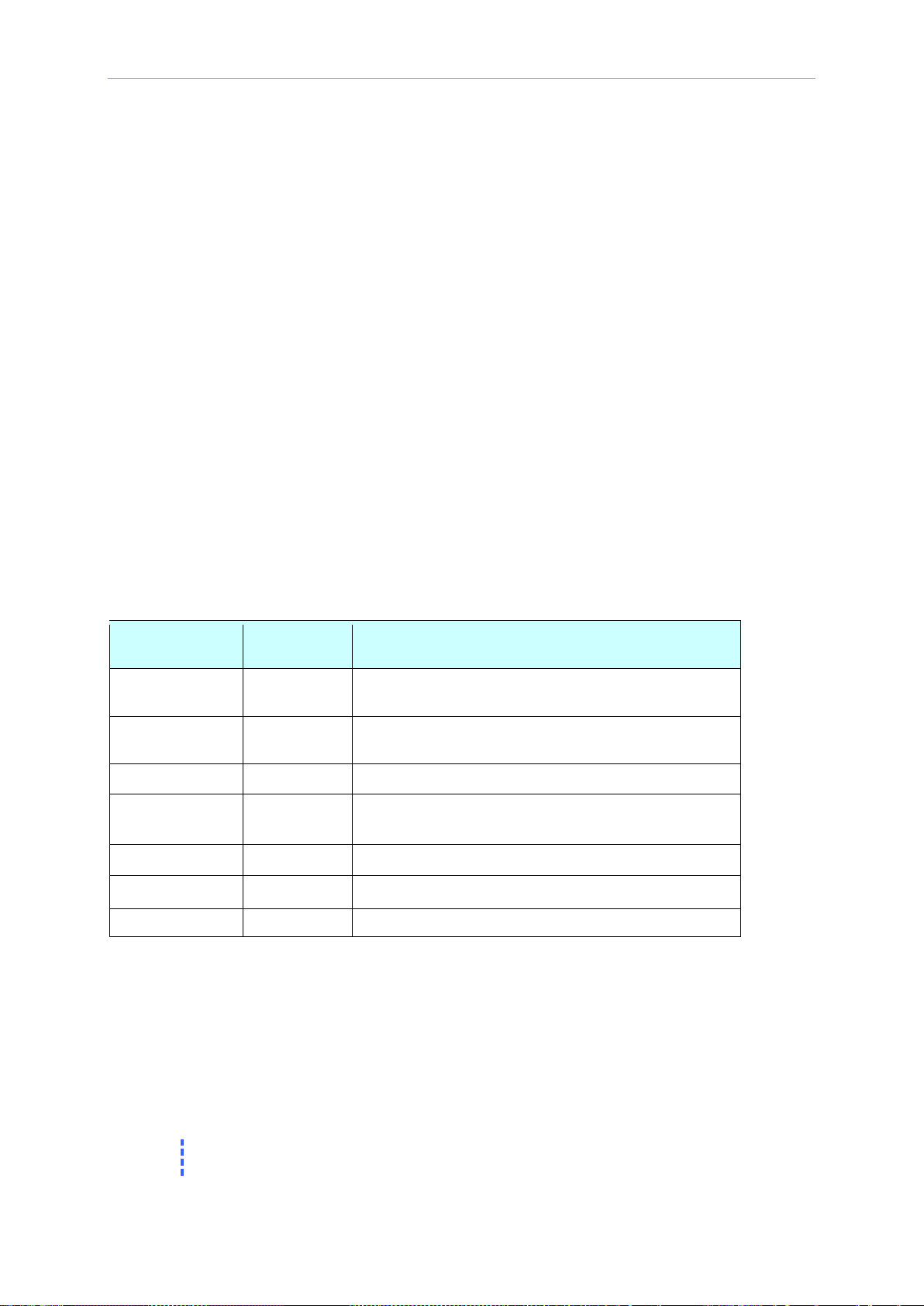
Programmable DC Power Supply 62000L Series User’s Manual
Bit
Decimal
value
Definition
0 Voltage
1
The power supply is/was in constant current
mode.
1 Current
2
The power supply is/was in constant voltage
mode.
2-7 Not used
0
Always set to 0.
8 OTP
256
The over temperature protection circuit has
9 OVP
512
The over voltage protection circuit has tripped.
10 OCP
1024
The over current protection circuit has tripped.
11-15 Not used
0
Always set to 0.
Note
An error status like Standard Event register bit 2, 3, 4, or 5 will record one or
more errors in the error queue. Use SYST:ERR? to read the error queue.
4.3.2.1 The Questionabl e Status Re gister
The Questionable Status register reports information about the power supply.
The bit 0 and bit 1 provides the information about the output CV/CC r egulat ion. If the power
supply is/was in CC (constant current) mode, the bit 0 sets to 1. If the power supply is/was in
CV (constant voltage) mode, the bit 1 sets to 1.
The bit 8 ~ bit 10 provides information that one of the protection event is tripped. If the over
temperature protection (OTP) tripped event is detected, bit 8 sets to 1. If the over voltage
protection (OVP) tripped event is detected, bit 9 sets to 1. If the over current protection (OCP)
tripped event is detected, bit 10 sets to 1.
To read the Questionable Status register, use the command below.
STATus:QUEStionable?.
Any or all of the Questionable Status Events can be reported in the Questionable Status
Summary bit (QUES, bit 3) of Status Byte register through the enable register. To set the
enable register mask, write a decimal value to the register using the following command.
STATus:QUEStionable:ENABle <value>.
The bits of Questionable Status register are latched can only cleared by the c ommand
STAT:QUES? or *CLS.
Bit definition – Questionable status register
tripped.
4.3.2.2 The Standard Event Register
The Standard Event register reports the types of instrument events, such as power-on
detected, command syntax errors, command execution errors, self-test or calibration errors,
query errors, or when executing *OPC. All of these statuses can be reported in the Standard
Event summary bit 5 of the Status Byte register via the enable register. To set the enable
register mask, you have to use *ESE to write a decimal value to the register.
4-20
Page 85
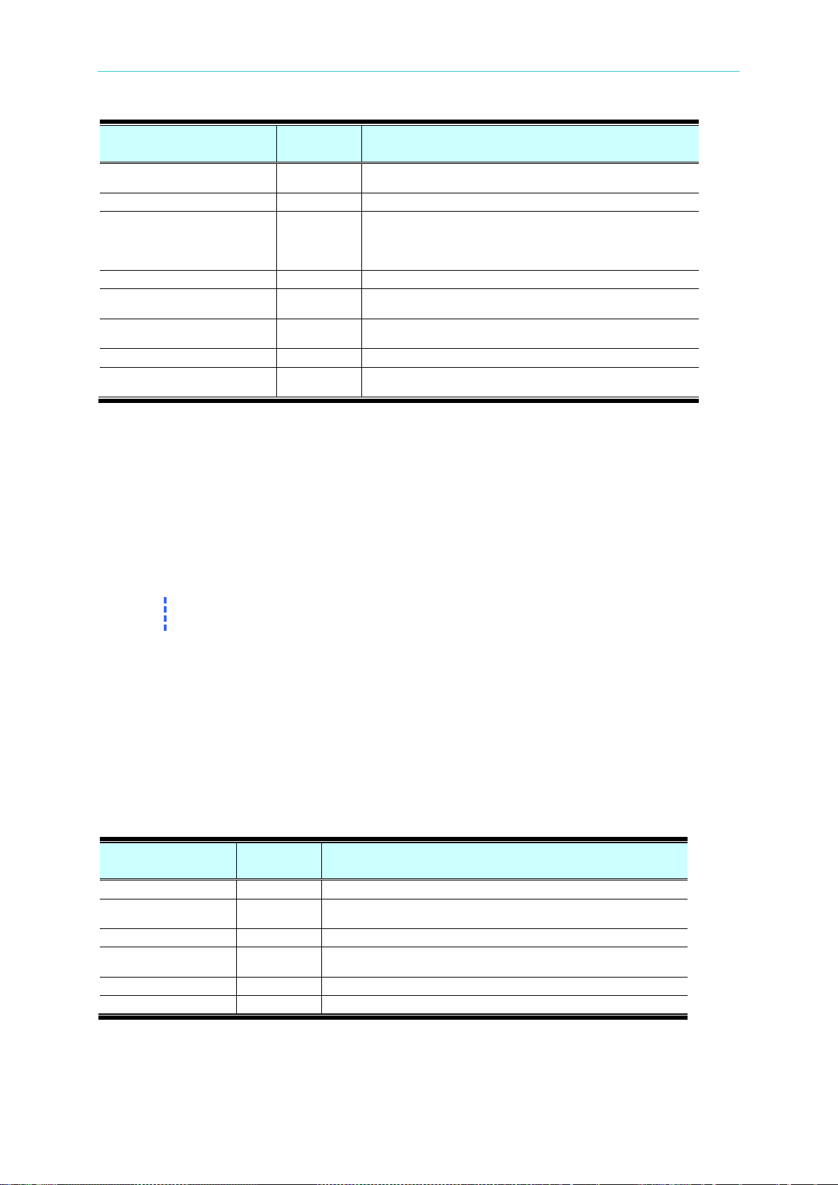
Remote Control Reference
Bit
Decimal
Value
Definition
0
OPC
1
Operation accomplished. All commands prior to and
including *OPC have been executed.
1
Not Used
0
Always set to 0.
2
QYE
4
Query Error. The power supply tried to read the output
I/O buffers are full.
3
DDE
8
Device Error. A self-test or calibration error occurred.
4
EXE
16
Execution Error. An execution error occurred. The Error
codes are within -211 to -221.
5
CME
32
Command Error. A command syntax error occurred. The
Error codes are within -101 to -178.
6
Not used
0
Always set to 0.
7
PON
128
Power On. Power has been turned off and on since the
last time the event register was read or cleared.
Note
You can’t clear the enable register at power-on if you have previously configured
the power supply with *PSC 0.
Bit Decimal
Value
Definition
0-2
Not Used
0
Always set to 0.
3
QUES
8
One or more bits are set in the Questionable Status register
(bits must be enabled in the enable register.)
4
MAV
16
Data is available in the output buffer.
5
ESB
32
One or more bits are set in the Standard Event register (bits
must be enabled in the enable register.)
6
RQS
64
The power supply is requiring service (Serial Poll).
7
Not Used
0
Always set to 0.
buffer, which is empty. Or, a new command line was
received before a preceding query had been read. Or, the
In addition, the Standard Event register will be cleared under the following conditions.
Execute *CLS.
Use *ESR? to query the event register. For example, 28 (4 + 8 + 16) is returned when the
status of the Standard Event register has been queried, and QYE, DDE, and EXE
condition have occurred.
In addition, the Standard Event Enable register will be cleared under the following conditions.
Execute *ESE 0.
Turn on the power supply, use *PSC 1 to configure the power supply.
4.3.2.3 The Status Byte Register
The Status Byte summary register can generate conditions from the other status registers.
Querying data that is waiting in the output buffer of the power supply is going to be
immediately generated through the “Message Available” bit (bit4) of the Status Byte register.
In addition, bits in the summary register are not locked. Clearing an event register will also
clear the corresponding bits in the Status Byte summary register. Reading all messages in the
output buffer and any pending queries will clear the message available bit.
When executing *CLS, the Status Byte summary register will be cleared. Using *ESR? to
query the Standard Event register will clear only bit 5 in the Status Byte summary register. For
4-21
Page 86
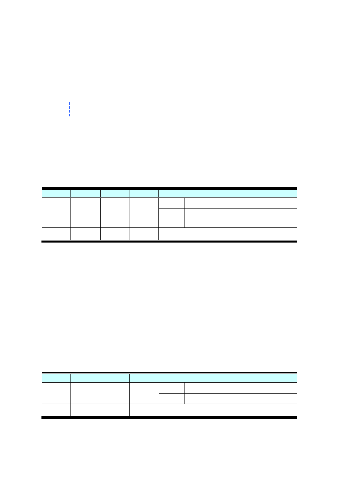
Programmable DC Power Supply 62000L Series User’s Manual
Note
If previously configuring the power supply with *PSC 0, the enable register won’t
be cleared at power-on.
Offset
Field
Size
Value
Definition
0
bNotify
1
Bitmap
D7
Must be 1. See the USBTMC specs.
D0~D6
The bTag value must be the same as the
request.
1
bNotify
1
Status
Byte
The IEEE-488.2 defined Status Byte returned during a
serial poll.
Offset
Field
Size
Value
Definition
0
bNotify1
1
Bitmap
D7
Must be 1. See the USBTMC specs.
D0~D6
bTag. The bTag field must be 0x01.
1
bNotify2
1
Status
Byte
The IEEE-488.2 defined Status Byte returned during a
serial poll.
example, 24 (8+16) will be returned when querying the status of the Status Byte register,
QUES and MAV conditions have occurred.
In addition, the Status Byte Enable register will be cleared under the following conditions.
Execute *SRE 0.
Turn on the power and previously configured the power supply with *PSC 1.
4.3.2.3.1 Read Status Byte Request
The power supply implements a 488.2 USB488 interface and the host may read the Status
Byte summary register at any time with the READ_STATUS_BYTE request. If the power
supply receives a READ_STATUS_BYTE request from the host, an USB488 Interrupt-IN
packet as shown as the following table.
bTag value in the READ_STATUS_BYTE
4.3.2.3.2 Service Request (SRQ)
When the request service bit (RQS, bit 6) in the Status Byte is set, an USB488 Interrupt-IN
packet due to a SRQ condition is queued to send to the host. Select which summary bits will
generate the service request by setting the Status Byte enable register with *SRE command.
If the response is queued, the Status Byte is modified in the same way an IEEE-488.2 device
modifies the Status Byte after a SRQ/serial poll sequence. This means the power s upply will
clear the RQS bit of the Status Byte register after a Status Byte (with RQS set) is queued to
be sent on the Interrupt-IN pipe.
The request service (RQS) bit is cleared only by queuing a response Interrupt-IN packet due
to the SRQ condition or by reading the event register whose summary bit is causing the
service request.
In addition, the following procedures present how to generate an SRQ interrupt.
Clear the output queue of the power supply.
Use *CLS to clear the event registers.
Use *ESE to set up the enable masks of Standard Event register. Use the command *SRE
4-22
Page 87

Remote Control Reference
to set up the enable masks of the Status Byte summary register.
Send *OPC? and enter the result to verify synchronization.
Now, if any of the conditions corresponding to the enabled summary bits in the Status
Byte register occurs, the power supply send a USB488 Interrupt-IN packet as shown as
the above table to the hos t.
4.3.2.3.3 Use *STB? to Read the Status Byte
*STB? is used to query the Status Byte register. The return value while querying the Status
Byte register is a decimal value that corresponds to the binary-weighted sum of the bits set in
the register. Since the request service bit (RQS, bit 6) of the Status Byte register is reported
and cleared by a SRQ process, you don’t have to read the state of the RQS bit with *STB.
Executing *STB? can’t clear the Status Byt e summary register.
4.3.2.3.4 The Message Available Bit (MAV)
The Message Available bit (MAV, bit 4) of the Status Byte summary register indicates that
data in the power supply's output queue is available to read into USB bus. The MAV bit is
cleared only after all messages have been read from the output queue.
4.3.2.3.5 Use *OPC
The Operation Complete bit (OPC, bit 0) of the Standard Event register indicates if a
command sequence is completed. After a *OPC command is executed, the OPC bit of the
Standard Event regis ter is set . Send *OP C after a query command that loads message into
output queue, and you can use the OPC bit to determine if the message is available. However,
the output queue will fill and the power supply will stop processing commands if there are too
many messages generated by the commands before the *OPC executes sequentially.
In addition, the following procedures present how to determine if a command sequence is
completed.
Clear the power supply's output queue.
Use *CLS to clear the event registers.
Execute *ESE 1 to enable the operation complete bit (OPC, bit 0) in the Standard Event
register.
Send *OPC? and enter the result to ensue synchronization.
Execute *OPC as the last command sequentially after the command string you use to
program the configuration of the power supply. The operation complete bit (OPC, bit 0) is
set in the Standard Event register when the command sequence is completed.
Check the standard event bit (ESB, bit 5) in the Status Byte summary register to
determine if the command sequence is completed. The power supply will also generate a
SRQ interrupt if you configure it.
4-23
Page 88

Page 89

Error Messages
5. Error Messages
When a syntax or hardware error has been detected, the front-panel Err annunciator turns on
and the power supply beeps once each time an error is generated. A record of up to 32 errors
is stored in the power supply’s error queue.
Errors are retrieved in first-in-first-out (FIFO) order. The first error that was stored first is
returned first. The Err annunciator turns off when all errors stored in the error queue have
been read.
If more than 32 errors have been detected, the most recent error (the last error stored in the
queue) is replaced with -350, “Too many errors.” No additional errors are stored until you
remove errors from the queue. Reading the error message stored in the queue will remove it
at the same time. If no errors are stored when you read the error queue, the power supply
responds with +0, “No Errors” over the remote interface or NO ERROR from the front panel
operation.
When the power supply has been powered off or after a *CLS (clear status) command has
been executed, the error queue is cleared. The *RST (reset) command does not clear the
error queue.
On the other hand, if all of the error messages are from execution, Self-Test, and calibration,
then the following sections will describe which error code represents the status.
Front-panel operation:
Press the ERROR key repeatedly to read the errors stored in the queue if the Err annunciator is on.
The error is removed from the queue after being read by user.
Remote interface operation:
Use SYSTem:ERRor? to read the latest error message from the error queue. The returned
error messages have the 73 following format.
-113,”Undefined header”
5.1 Execution Errors
-101 Invalid Character
There is one or more invalid character in the command string. Characters such as #, $, or %
are not available in a command and may have been inserted in the command keyword or
within a parameter.
Example: #VOLT 10
-102 Syntax Error
There is one or more syntax error in the command string. You may have inser t ed a blank
space before or after a colon in the command header, or before a comma.
Example: VOLT:LEV ,10
-103 Invalid Separator
5-1
Page 90

Programmable DC Power Supply 62000L Series User’s Manual
There is one or more invalid separator in the command string. You may have used a comma
instead of a colon, semicolon, or blank space; or you may have used a blank space instead of
a comma.
Example: VOLT,10
-108 Parameter not Allowed
More parameters than expected for the command were received. You may have added a
parameter to a command that does not accept a parameter or you entered extra parameters
for the command.
Example: *OPC 1
-109 Missing parameter
Fewer parameters than expected for the command were received. One or more parameters
that are required for the command were omitted.
Example: VOLT:LEV
-113 Undefined Header
A command that is not valid for this power supply was r eceived. The command may not be a
valid one or you have misspelled i t. If you are using the short form of the co mmand , reme mber
that it the maximum length is four letters.
Example: TRIGG:DEL 3
-121 Invalid Character in Number
An invalid character was found in the number specified for a parameter value.
Example: *ESE B01010102
-124 Too Many Digits
The received numeric parameter was found that contained more than 21 digits.
-131 Invalid Suffix
A suffix was incorrectly specified for a numeric parameter. You may hav e misspelled the suffix
or the suffix is not available for the parameter.
-138 Suffix not Allowed
The received parameter contains suffix that not accept by the command.
Example : CURR 1V
-141 Invalid Character Data
Invalid character data was found. The character data element may contain an invalid
character or the particular element received was not valid for the header.
-144 Invalid character data length
There are too many characters in the character data.
Example : CAL:SEC:CODE 01234567
-151 Invalid String Data
5-2
Page 91

Error Messages
An invalid character string was received. Check to see if you have enclosed the character
string in single or double quotes.
Example : DISP:TEXT “HELLO
-211 Trigger Ignored
A Group Execute Trigger (GET) or *TRG was received but the trigger w as ignored. Make sure
that the trigger source should be selected to the bus and the trigger subsystem should be
initiated by INIT[:IMM] command.
-213 Init ignored
An INITiate command has received but could not to execute because of current device
settings.
-221 Settings Conflict
Indicate that the operation can not complete under present states of the power supply. For
example, try to change the output sequence step settings without turning off the output first
will generate this error.
-222 Data out of Range
The value of the numeric parameter for the command is outside the valid range.
Example: VOLT:LEV -3
-224 Illegal Parameter Value
A discrete parameter was received but did not accept by the command. You may have used
an invalid parameter choice. Check the parameter list and choose a correct one.
Example: DISP MAX (MAX is not a valid choice).
-330 Self-test Failed
The complete self-test of the power supply from the remote interface (*TST? Command) failed.
In addition to this error, more specific self-test errors are also reported.
-350 Too many errors
Too many errors occurred (more than 32 errors) and the error queue is overflow. No
additional errors are stored until you remove errors from the queue. Reading the error
message stored in the queue will remove it at the same time. The error queue is cleared when
the power supply has been powered off, or after a *CLS (clear status) command has been
executed.
-410 Query INTERRUPTED
A command which sends data to the output buffer was received, but there were data from a
previous command still in the output buffer (the previous data is not overwritten). The output
buffer is cleared when the power supply has been powered off, or after a *RST (reset)
command has been executed.
-420 Query UNTERMINATED
The power supply was requested to talk (i.e., to send data over the interface) but a comm and
which sends data to the output buffer has not been received. For example, you may have
executed an APPLy command (which does not generate data) and then attempted an ENTER
statement to read data from the remote interface.
-430 Query DEADLOCKED
5-3
Page 92

Programmable DC Power Supply 62000L Series User’s Manual
A command which generates too much data to fit in the output buffer was received and the
input buffer is also full. Command execution continues but all data are lost.
-440 Query UNTERMINATED after Indefinite Response
The *IDN? Command must be the last query command within a command string. Any query
command after *IDN? generates this error.
Example: *IDN?;:SYST:VERS?
501 Isolator UART framing error
Internal UART communication failed.
5.2 Self-Test Errors
The following errors indicate failures that may occur during a self-test.
602 DATA read/write failed
Failed to read data stored from non-volatile memory or write data to it.
632 Hardware test failed
634 Connection test failed
5.3 Calibration Errors
The following errors indicate failures that may occur during a calibration. Refer to the Service
Guide for more information.
701 Cal security disabled by master code
Calibration security has disabled by master code.
702 Cal Secured
The power supply is secured and calibration is not allowed.
703 Invalid Secure Code
The security code attempt to unsecure or secure the power supply was wrong. Use the
security code that the same as what you used to secure the power supply to unsecure it, and
vice versa. The security codes should be a 6 alphanumeric characters string without quotes.
705 Cal aborted
A calibration progress is aborted.
706 Cal invalid data value
Received calibration data is out of range.
708 Cal Invalid Command
A command which is not available in calibration mode, for example OUTP OFF, was receiv ed.
709 Cal initialize failed
Failed to initialize calibration progress.
5-4
Page 93

Error Messages
711 Cal Sequence Interrupted
Calibration sequence was interrupted. You may lose some steps in calibration procedure.
712 Bad DAC Cal Data
Failed to calibrate internal DAC.
714 Bad OVP cal data
715 Bad OCP cal data
5-5
Page 94

Page 95

Chroma’s Continuous Quality Process
User Manual Customer Feedback
Chroma welcomes all comments and recommendations to improve this publication in the
future editions. Please scan the QR code below or click the URL
http://www.chromaate.com/survey?n=793ce6db-17ef-4cd3-b0de-8bbd09aa38e0
customer feedback form. Thank you!
to fill in the
Page 96

Copyright by CHROMA ATE INC. All Rights Reserved.
CHROMA ATE INC.
致茂電子股份有限公司
66 Huaya 1st Road, Guishan,
Taoyuan 33383, Taiwan
台灣桃園市 33383 龜山區
華亞一路 66 號
T +886-3-327-9999
F +886-3-327-8898
Mail: [email protected]
http://www.chromaate.com
All other trade names referenced are the properties of their respective companies.
 Loading...