

Chroma 62020H-150S, 62100H-600S, 62050H-600S, 62000H Series, 62150H-1000S Operating & Programming Manual
...Page 1

Page 2

Page 3

Programmable DC Power Supply
(with Solar Array Simulation)
62000H Series
Operating & Programming
Manual
Version 1.9
August 2017
Page 4

ii
Legal Notices
The information in this document is subject to change without notice.
Chroma ATE INC. makes no warranty of any kind with regard to this manual, including, but
not limited to, the implied warranties of merchantability and fitness for a particular purpose.
Chroma ATE INC. shall not be held liable for errors contained herein or direct, indirect, special,
incidental or consequential damages in connection with the furnishing, performance, or use of
this material.
CHROMA ATE INC.
66 Huaya 1st Road, Guishan, Taoyuan 33383, Taiwan
Copyright Notices. Copyright 2010 Chroma ATE INC., all rights reserved. Reproduction,
adaptation, or translation of this document without prior written permission is prohibited,
except as allowed under the copyright laws.
Page 5

iii
Warranty
All of Chroma’s instruments are warranted against defects in material and workmanship for a
period of one year from date of shipment. Chroma agrees to repair or replace any assembly
or component found to be defective, under normal use during this period. Chroma’s obligation
under this warranty is limited solely to repairing any such instrument, which in Chroma’s sole
opinion proves to be defective within the scope of the warranty when returned to the factory or
to an authorized service center. Purchaser is responsible for the shipping and cost of the
service item to Chroma factory or service center. Shipment should not be made without prior
authorization by Chroma.
This warranty does not apply to any p roducts rep aired o r altered by persons not authorized by
Chroma, or not in accordance with instructions furnished by Chroma. If the instrument is
defective as a result of misuse, improper repair, or abnormal conditions or operations, repairs
will be billed at cost.
Chroma assumes no responsibility for its product being used in a hazardous or dangerous
manner either alone or in conjunction with other equipment. High voltage used in some
instruments may be dangerous if misused. Special disclaimers apply to these instruments.
Chroma assumes no liability for secondary charges or consequential damages and in any
event, Chroma’s liability for breach of warranty under any contract or otherwise, shall not
exceed the purchase price of the specific instrument shipped and against which a claim is
made.
Any recommendations made by Chroma regarding the use of its products are based upon
tests believed to be reliable; Chroma makes no warranty of the results to be obtained. This
warranty is in lieu of all other warranties, expressed or implied, and no representative or
person is authorized to represent or assume for Chroma any liability in connection with the
sale of our products other than set forth herein.
CHROMA ATE INC.
66 Huaya 1st Road, Guishan,
Taoyuan 33383, Taiwan
Tel: 886-3-327-9999
Fax: 886-3-327-8898
e-mail: info@chromaate.com
http://www.chromaate.com
Page 6

iv
Material Contents Declaration
Hazardous Substances
Lead
Mercury
Cadmium
Hexavalent
Polybrominated
Polybromodiphenyl
Pb
Hg
Cd
Cr6+
PBB
PBDE
“O” indicates the level of the specified chemical substance is less than the threshold level
specified in the SJ/T
“
specified in the SJ/T
The recycling label on the product indicates the Hazardous Substances contained in the
product as shown in the tables below.
: See <Table 1>.
: See <Table 2>.
<Table 1>
Part Name
PCBA
CHASSIS
ACCESSORY
PACKAGE
” indicates the level of the specified chemical substance exceeds the threshold level
Disposal
Do not dispose of electrical appliances as unsorted municipal waste; use separate collection
facilities. Contact your local government for information regarding the collection systems
available. If electrical appliances are disposed of in landfills or dumps, hazardous substances
can leak into the groundwater and get into the food chain, damaging your health and
well-being. When replacing old appliances with new ones, the retailer is legally obligated to
take back the old appliances for disposal free of charge.
O O O O O O
O O O O O O
O O O O O O
O O O O O O
-11363-2006 and EU 2005/618/EC standards.
-11363-2006 and EU 2005/618/EC standards.
Chromium
Biphenyls
Ethers
Page 7

v
<Table 2>
Hazardous Substances
Lead
Mercury
Cadmium
Hexavalent
Polybrominated
Polybromodiphenyl
Pb
Hg
Cd
Cr6+
PBB
PBDE
“O” indicates the level of the specified chemical substance is less than the threshold level
specified in the
“
specified in the SJ/T
1.
2.
environment specified in each product’s specification.
Part Name
PCBA
CHASSIS
ACCESSORY
PACKAGE
O O O O O O
O O O O O
O O O O O
O O O O O
Chromium
Biphenyls
Ethers
SJ/T-11363-2006 and EU 2005/618/EC standards.
” indicates the level of the specified chemical substance exceeds the threshold level
-11363-2006 and EU 2005/618/EC standards.
Chroma has not fully transitioned to lead-free solder assembly at this moment; however,
most of the components used are RoHS compliant.
The environment-friendly usage period of the product is assumed under the operating
Disposal
Do not dispose of electrical appliances as unsorted municipal waste; use separate collection
facilities. Contact your local government for information regarding the collection systems
available. If electrical appliances are disposed of in landfills or dumps, hazardous substances
can leak into the groundwater and get into the food chain, damaging your health and
well-being. When replacing old appliances with new ones, the retailer is legally obligated to
take back the old appliances for disposal free of charge.
Page 8

vi
Page 9

vii
Page 10
viii
Page 11

ix
Page 12
x
Page 13
xi
Page 14

xii
Page 15

xiii
Safety Summary
BEFORE APPLYING POWER
PROTECTIVE GROUNDING
NECESSITY OF PROTECTIVE GROUNDING
FUSES
DO NOT OPERATE IN AN EXPLOSIVE ATMOSPHERE
good
DO NOT REMOVE THE COVER OF THE INSTRUMENT
current is set and outputting may result in personal injury or death.
WARNING
The following general safety precautions must be observed during all phases of operation,
service, and repair of this instrument. Failure to comply with these precautions or specific
WARNINGS given elsewhere in this manual will violate safety standards of design,
manufacture, and intended use of the instrument. Chroma assumes no liability for the
customer’s failure to comply with these requirements.
Verify that the power is set to match the rated inp ut o f this power supply.
Connect the protective grounding cables to a good earth ground to
prevent an electric shock before turning on the power.
Never cut off the internal or external protective grounding wire, or
disconnect the wiring of the protective grounding terminal. Doing so
will cause a potential shock hazard that may cause injury to a person.
Only fuses with the required rated current, voltage, and specified type
(normal blow, time delay, etc.) should be used. Do not use repaired
fuses or short-circuited fuse holders. To do so could cause a shock or
fire hazard.
Do not operate the instrument in the presence of flammable gases or
fumes. The instrument should only be used in an environment with
ventilation.
Operating personnel must not remove the cover of the instrument.
Component replacement and internal adjustment should only be done
by qualified service personnel.
Touching the output terminal on the rear panel when the power or
Page 16

xiv
Safety Symbols
The Notice sign highlights an essential operating or maintenance
procedure, condition, or statement.
WARNING
CAUTION
DANGER – High voltage.
Explanation: To avoid injury, death of personnel, or damage to the
instrument, refer to the explanation in the instruction manual.
High temperature: This symbol indicates the temperature is
hazardous to human beings. To prevent personal injury, do not touch
the object.
Protective grounding terminal: This symbol indicates that the
terminal must be connected to ground before operation of the
equipment to protect against electrical shock in case of a fault.
Functional grounding: Identifies an earth (ground) terminal in cases
where the protective ground is not explicitly stated. This symbol
indicates the power connector does not provide grounding.
Frame or chassis: Identifies a frame or chassis terminal.
Alternating Current (AC)
Direct Current (DC) / Alternating Current (AC)
Direct Current (DC)
Push-on/Push-off power switch
The WARNING sign highlights an essential operating or maintenance
procedure, practice, condition, statement, etc., which if not strictly
observed, could result in injury to, or death of, personnel or long term
health hazards.
The CAUTION sign highlights an essential operating or maintenance
procedure, practice, condition, statement, etc., which if not strictl y
observed, could result in damage to, or destruction of, equipment.
Page 17

xv
Revision History
Date
Version
Revised Sections
May 2010
1.0
Complete this manual.
Aug. 2010
1.1
Modify the following sections to add new model 62150H-1000S and I-V
– “IV Subsystem” in the chapter of “Remote Operation”
Apr. 2011
1.2
Add the following in the chapter of “Overview” & “Remote Operation”:
and main power switch
Nov. 2011
1.3
Add A620028 and A620027 SLAVE models in the manual.
Aug. 2012
1.4
Update the following:
Operation”
Oct. 2013
1.5
Add the following functions (only applicable when the firmware is
section of “SAS Subsystem”
Jul. 2014
1.6
Add Model 62020H-150S along with its specifications and usage
descriptions in the manual.
Mar. 2015
1.7
Update the following:
The output connecting cables diagram for Model 62020H-150S.
The following lists the additions, deletions and modifications in this manual at each revision.
Curve Programming function:
– “Specifications” and “Other Specifications” as well as Notes in the
chapter of “Overview”
– “Specification of Parallel Capacitance “ in the chapter of
“Installation”
– “Setting Configuration “ and “SERIES/PARALLEL “ in the chapter
of “Manual Operation”
Add the following:
– Suggested O type terminal specification in the section of “Input
Connection” under “Installation”
– “SAS Subsystem” in the chapter of “Remote Operation”
Update the following:
– “TABLE MODE” and “SAS MODE” section in the chapter of
“Manual Operation”
– Specification of model 62050H-600S
– Two reference figures in the “CAUTION” under Specification
– TRIG command to “SAS Subsystem”
Update the following in the chapter of “Overview”:
– Specification of 62150H-1000S
– The figure of front panel of 62000H with Solar Array Simulation
− Description in “Specification” section
− Value of minimum output voltage in “Other Specifications” section
− Notice in “Checking the Package” section
− Notice in “SERIES/PARALLEL” section
− Notice in “Assembling Series/Parallel Communication Interface”
section
Add “D/D FAULT Protection” section in the chapter of “Manual
upgraded to 2.00):
− “CURR. SHARING ERR Protection”, “FPGA UPDATE!
Protection”, “C/S CABLE ERR. Protection”, “MATCH Warning”,
“RS485 PARSER”, “EN50530 MODE” and “SANDIA_ MODE”
sections in the chapter of “Manual Operation”
− “EN50530 MODE” and “SANDIA_ MODE” description in the
− The figure of rear panel.
−
Page 18

xvi
Oct. 2016
1.8
Update CE “Declaration of Conformity”.
Aug. 2017
1.9
Revised text throughout the manual.
Page 19

Programmable DC Power Supply (with Solar Array Simulation) 62000H Series
xvii
Operating & Programming Manual
Table of Contents
1. Overview ........................................................................................................... 1-1
1.1 Introduction ......................................................................................................... 1-1
1.2 System Functions ............................................................................................... 1-1
1.2.1 Operating Modes ......................................................................................... 1-1
1.2.2 Protection .................................................................................................... 1-1
1.2.3 Output/Indication ......................................................................................... 1-2
1.2.4 Input Control Signals ................................................................................... 1-2
1.2.5 Measuring & Editing .................................................................................... 1-2
1.3 Specifications ...................................................................................................... 1-2
1.3.1 Other Specifications .................................................................................... 1-4
1.4 Function Keys ................................................................................................... 1-10
1.4.1 Front Panel ............................................................................................... 1-10
1.4.2 Rear Panel ................................................................................................ 1-12
2. Installation ........................................................................................................ 2-1
2.1 Checking the Package ........................................................................................ 2-1
2.1.1 Maintenance & Cleaning ............................................................................. 2-2
2.2 Preparation for Use ............................................................................................. 2-2
2.2.1 Normal Environment Conditions .................................................................. 2-3
2.3 Input Power Requirements .................................................................................. 2-3
2.3.1 Ratings ........................................................................................................ 2-3
2.3.2 Input Connections ....................................................................................... 2-3
2.4 Remote Sensing ................................................................................................. 2-5
2.4.1 Correct Connection ..................................................................................... 2-5
2.4.2 Reverse Connection of Remote Sensing Wire Polarity ................................ 2-7
2.5 Output Connection .............................................................................................. 2-7
2.5.1 Rear Panel Output....................................................................................... 2-7
2.5.2 Connecting Wire Specifications ................................................................... 2-9
2.5.3 Parallel Capacitance Specifications ........................................................... 2-10
2.5.4 Installing the Handle (62150H for example) ............................................... 2-10
2.6 Power-On Procedure ........................................................................................ 2-11
3. Manual Operation ............................................................................................. 3-1
3.1 Introduction ......................................................................................................... 3-1
3.2 Setti ng Voltage & Current ................................................................................... 3-1
3.3 Setti ng Configuration .......................................................................................... 3-2
3.3.1 SYSTEM SETUP ........................................................................................ 3-5
3.3.1.1 APG ........................................................................................................ 3-5
3.3.1.2 BUZZER ................................................................................................ 3-10
3.3.1.3 POWER ON STATUS ........................................................................... 3-10
3.3.2 OUTPUT SETUP ...................................................................................... 3-12
3.3.2.1 VOLTAGE LIMIT SETTING ................................................................... 3-13
3.3.2.2 CURRENT LIMIT SETTING .................................................................. 3-14
3.3.2.3 VOLTAGE SLEW RATE ........................................................................ 3-15
3.3.2.4 CURRENT SLEW RATE SETTING ....................................................... 3-16
3.3.2.5 Setting DC_ON ...................................................................................... 3-17
3.3.2.6 Setting IV CURVE Parameters .............................................................. 3-18
3.3.3 SERIES/PARALLEL .................................................................................. 3-21
3.3.3.1 Connecting Series/Parallel Output Cables ............................................. 3-22
3.3.3.2 Assembling Series/Parallel Communication Interface ............................ 3-22
3.3.3.3 Setting Series/Parallel Operation Mode ................................................. 3-25
3.3.3.4 Setting Series Parameters ..................................................................... 3-30
Page 20

Programmable DC Power Supply (with Solar Array Simulation) 62000H Series
xviii
Operating & Programming Manual
3.3.3.5 Setting Parallel Parameters ................................................................... 3-32
3.3.3.6 Setting Procedure for APG in Series or Parallel ..................................... 3-34
3.3.4 DISPLAY ................................................................................................... 3-36
3.3.4.1 BRIGHTNESS ....................................................................................... 3-36
3.3.4.2 DISPLAY SELECTION .......................................................................... 3-37
3.3.4.3 READING AVERAGE TIMES ................................................................ 3-39
3.3.5 PROTECTION ........................................................................................... 3-40
3.3.5.1 OVP Protection ...................................................................................... 3-40
3.3.5.2 OCP Protection ..................................................................................... 3-41
3.3.5.3 OPP Protection ...................................................................................... 3-42
3.3.5.4 REMOTE INHIBIT ................................................................................. 3-43
3.3.5.5 SAFETY INT.LOCK ............................................................................... 3-45
3.3.5.6 EXTERNAL ON/OFF ............................................................................. 3-47
3.3.5.7 FOLDBACK ........................................................................................... 3-48
3.3.5.8 OTP ....................................................................................................... 3-50
3.3.5.9 AC FAULT ............................................................................................. 3-51
3.3.5.10 SENSE FAULT Protection ................................................................. 3-51
3.3.5.11 FANLOCK Protection......................................................................... 3-52
3.3.5.12 D/D FAULT Protection ....................................................................... 3-53
3.3.5.13 CURR. SHARING ERR Protection..................................................... 3-53
3.3.5.14 FPGA UPDATE! Protection ............................................................... 3-54
3.3.5.15 C/S CABLE ERR. Protection ............................................................. 3-55
3.3.5.16 MATCH Warning ............................................................................... 3-56
3.3.6 FACTORY SETTING ................................................................................. 3-56
3.3.7 CALIBRATION .......................................................................................... 3-57
3.3.7.1 Voltage Output & Measurement Calibration ........................................... 3-60
3.3.7.2 Current Measurement Calibration .......................................................... 3-62
3.3.7.3 Current Output (PROG.) Calibration ...................................................... 3-65
3.3.7.4 APG Voltage Calibration ........................................................................ 3-69
3.3.7.5 APG Current Calibration ........................................................................ 3-72
3.3.7.6 IV Voltage Output & Measurement Calibration (62020H-150S Only) ..... 3-74
3.3.7.7 IV Current Calibration (62020H-150S Only) ........................................... 3-77
3.3.8 REMOTE SETUP ...................................................................................... 3-80
3.3.8.1 GPIB ADDRESS ................................................................................... 3-80
3.3.8.2 ETHERNET ........................................................................................... 3-80
3.3.8.3 RS232/RS485 ....................................................................................... 3-82
3.3.8.4 BAUDRATE ........................................................................................... 3-83
3.3.8.5 RS485 ADDR ........................................................................................ 3-83
3.3.8.6 RS485 TERMINATOR ........................................................................... 3-84
3.3.8.7 RS485 PARSER .................................................................................... 3-84
3.3.9 OUTPUT MODE ........................................................................................ 3-85
3.3.9.1 CV/CC MODE ....................................................................................... 3-86
3.3.9.2 TABLE MODE ....................................................................................... 3-86
3.3.9.3 SAS MODE ........................................................................................... 3-88
3.3.9.4 EN50530 MODE .................................................................................... 3-92
3.3.9.5 SANDIA MODE ..................................................................................... 3-93
3.3.9.6 Error Message ....................................................................................... 3-95
4. Program Sequence ........................................................................................... 4-1
4.1 LIST MODE ........................................................................................................ 4-1
4.1.1 Description of PROGRAM Settings ............................................................. 4-2
4.1.1.1 Setting EXT._TRIG PULL ........................................................................ 4-3
4.1.1.2 Setting PROG NO. .................................................................................. 4-3
4.1.1.3 Setting RUN COUNT ............................................................................... 4-3
Page 21

Programmable DC Power Supply (with Solar Array Simulation) 62000H Series
xix
Operating & Programming Manual
4.1.1.4 Setting PROG CHAIN .............................................................................. 4-5
4.1.1.5 Setting CLEAR PROGRAM ..................................................................... 4-8
4.1.2 Setting Sequence ........................................................................................ 4-9
4.1.2.1 Setting Sequence Number .................................................................... 4-10
4.1.2.2 Setting Sequence Type ......................................................................... 4-10
4.1.2.3 Setting Time .......................................................................................... 4-14
4.1.2.4 Setting Voltage ...................................................................................... 4-14
4.1.2.5 Setting Voltage Slew Rate ..................................................................... 4-14
4.1.2.6 Setting Current ...................................................................................... 4-14
4.1.2.7 Setting Current Slew Rate ..................................................................... 4-15
4.1.3 Execution in LIST MODE........................................................................... 4-15
4.1.3.1 Running LIST MODE ............................................................................. 4-15
4.1.3.2 Program List Mode Description ............................................................. 4-16
4.2 V_STEP MODE ................................................................................................ 4-16
4.2.1 Setting V_STEP MODE ............................................................................. 4-17
4.2.1.1 Setting START_VOLTAGE .................................................................... 4-17
4.2.1.2 Setting END_VOLTAGE ........................................................................ 4-18
4.2.1.3 Setting RUN_TIME ................................................................................ 4-18
4.2.2 Execution of V_STEP MODE .................................................................... 4-19
4.2.2.1 Running V_STEP MODE ....................................................................... 4-19
4.2.2.2 Description of Program V_Step Mode ................................................... 4-20
4.3 IV PROGRAM ................................................................................................... 4-20
4.3.1 Setting IV-PROGRAM ............................................................................... 4-21
4.3.2 Setting IV-Sequence ................................................................................. 4-22
4.3.2.1 Setting Sequence Number .................................................................... 4-22
4.3.2.2 Setting IV-FILE Number ........................................................................ 4-23
4.3.2.3 Setti ng Sequence Type ......................................................................... 4-23
4.3.2.4 Setting Time .......................................................................................... 4-24
4.3.3 Execution of IV PROGRAM ....................................................................... 4-25
4.3.3.1 Running IV PROGRAM ......................................................................... 4-25
4.3.3.2 IV Program Main Screen ....................................................................... 4-26
5. Remote Operation ............................................................................................ 5-1
5.1 Overview ............................................................................................................. 5-1
5.1.1 USB Interface .............................................................................................. 5-1
5.1.2 Setting GPIB, Ethernet, RS-232C & RS-485 Parameters ............................ 5-1
5.1.3 Connecting RS-232C .................................................................................. 5-1
5.1.4 Connecting RS-485 ..................................................................................... 5-2
5.1.5 Ethernet Remote Control ............................................................................. 5-3
5.1.5.1 Selecting the LAN to be Connected ......................................................... 5-4
5.1.5.2 Setting IP, Subnet Mask & Gateway ........................................................ 5-6
5.1.5.3 Confirming Network Connected Successfully ........................................ 5-11
5.1.5.4 Communicating with the Instrument ....................................................... 5-13
5.2 GPIB Function of 62000H Series ...................................................................... 5-19
5.3 Introduction to Programming ............................................................................. 5-19
5.3.1 Conventions .............................................................................................. 5-20
5.3.2 Numerical Data Formats............................................................................ 5-20
5.3.3 Boolean Data Format ................................................................................ 5-20
5.3.4 Character Data Format .............................................................................. 5-20
5.3.5 Basic Definition ......................................................................................... 5-21
5.3.5.1 Command Tree Structure ...................................................................... 5-21
5.3.5.2 Program Headers .................................................................................. 5-21
5.3.5.3 Common Command and Query Headers ............................................... 5-21
5.3.5.4 Instrument-Controlled Headers .............................................................. 5-21
Page 22

Programmable DC Power Supply (with Solar Array Simulation) 62000H Series
xx
Operating & Programming Manual
5.3.5.5 Program Header Separator (:) ............................................................... 5-21
5.3.5.6 Program Message ................................................................................. 5-21
5.3.5.7 Program Message Unit .......................................................................... 5-22
5.3.5.8 Program Message Unit Separator (;) ..................................................... 5-22
5.3.5.9 Program Message Terminator (<PMT>) ................................................ 5-22
5.4 Traversal of the Command Tree ....................................................................... 5-22
5.5 Execution Order ................................................................................................ 5-22
5.6 DC Power Supply Commands ........................................................................... 5-23
5.6.1 Common Command Syntax ...................................................................... 5-23
5.6.2 Specific Commands for 62000H Series ..................................................... 5-27
5.6.2.1 ABORT Subsystem ............................................................................... 5-27
5.6.2.2 CONFIGURE Subsystem ...................................................................... 5-27
5.6.2.3 SOURCE Subsystem ............................................................................ 5-33
5.6.2.4 FETCH Subsystem ................................................................................ 5-36
5.6.2.5 MEASURE Subsystem .......................................................................... 5-37
5.6.2.6 PROGRAM Subsystem ......................................................................... 5-37
5.6.2.7 IV Subsystem ........................................................................................ 5-42
5.6.2.8 SAS Subsystem .................................................................................... 5-46
5.6.2.9 OUTPUT Subsystem ............................................................................. 5-49
5.6.2.10 SYSTEM Subsystem ......................................................................... 5-50
6. Theory of Operation ......................................................................................... 6-1
6.1 Overview ............................................................................................................. 6-1
6.2 Function Description ........................................................................................... 6-3
6.2.1 I/P (PFC) Stage ........................................................................................... 6-3
6.2.2 Auxiliary Power ........................................................................................... 6-4
6.2.3 Output Stage ............................................................................................... 6-4
6.2.4 Digital Circuit ............................................................................................... 6-4
7. ETHERNET Functions (62020H-150S Only) .................................................... 7-1
7.1 Usage of Web Page ............................................................................................ 7-1
7.1.1 Home Page (index.html) .............................................................................. 7-1
7.1.2 Configuration Page...................................................................................... 7-2
7.1.3 Soft Panel ................................................................................................... 7-4
7.1.4 SCPI ........................................................................................................... 7-5
7.1.5 Remarks ...................................................................................................... 7-5
7.2 62020H-150S ETHERNET Simple Operation ..................................................... 7-6
7.2.1 ETHERNET SETUP Page ........................................................................... 7-6
7.2.2 Power Indicator & MAC Address Display ..................................................... 7-7
7.3 LAN Configuration Initialize (LCI) Function .......................................................... 7-7
7.3.1 IP Settings ................................................................................................... 7-8
7.3.2 Status Indicator ........................................................................................... 7-8
8. Self Test & Troubleshooting ............................................................................ 8-1
8.1 Overview ............................................................................................................. 8-1
8.2 Troubleshooting .................................................................................................. 8-1
Appendix A APG & System Status Pin Assignment ................................................ A-1
Appendix B List of Protection Messages ................................................................. B-1
Page 23

Overview
1-1
1. Overview
1.1 Introduction
Chroma 62000H Series Programmable DC Power Supplies with Solar Array Simulation are
high power density power supplies that provide stable DC output and accurate measurement
of voltage and current.
62000H Series DC Power Supplies with Solar Array Simulation have the following features:
(1) The output can simulate the I-V curve of a solar panel module in the Programming Mode.
(2) Voltage mode with two control loops to provide a stable, quick response output.
(3) The ability to set the slew rates of the output voltage and current.
(4) High power density output; the maximum output power can be as high as 15kW in a unit
under 3U in height.
(5) 16-bit ADC/16-bit DAC to provide excellent resolution.
(6) Lower transient spike and transient response time to insure the unit under test receives a
stable output and protection under load variations.
(7) Editing mode (Programming Mode) for output waveforms to provide multiple output
voltage and current combinations in real time for extended time period tests.
(8) Rotary knob and keyboard controls on the front panel to set the output voltage and
current.
(9) VFD panel: a high brightness, wide viewing angle interface for monitoring and setting
functions.
(10) Remote control via GPIB/Ethernet (option), USB, RS-232/RS-485, or Analog
Programmable (APG) interface.
1.2 System Functions
1.2.1 Operating Modes
(1) Local operation using the keyboard and rotary knob on the front panel.
(2) Remote operation using a GPIB/Ethernet (option), USB or RS-232/RS-485 interface.
(3) Through the APG input to control the output using analog signals.
(4) The setting and editing of I-V curves is provided by the Solar Array Simula tion Soft Panel.
1.2.2 Protection
(1) Protection is provided for voltage phase loss, input over-voltage or under-voltage, output
over-voltage, over-current, over-power, over-temperature, fan fail, CV/CC foldback, etc.
(2) Fan speed is controlled by the internal temperature of the power supply.
Page 24

Programmable DC Power Supply (with Solar Array Simulation) 62000H Series
1-2
Operating & Programming Manual
1.2.3 Output/Indication
(1) Auxiliary power output (12Vdc/10mA).
(2) Analog monitors (V/I) continuously send an output signal. This allows signals to be easily
monitored by external instruments (DMM, Oscilloscope, etc.). Ability to set the output
level indication (DC O N) sig n al.
(3) Output indicator (DC ON) signal.
(4) Protection state indication (OVP/OCP/OPP /FAN LOCK/AC FAULT, etc.).
(5) Over temperature (OTP) protection signal.
(6) CV/CC status indicator s .
(7) Output status indicators.
1.2.4 Input Control Signals
(1) Remote sense input for voltage drop compensation.
(2) Analog reference voltage (APG) i nput allowing voltage and current to be set by a voltage
source, current source, or resistance that adjusts for the panel setting.
(3) Remote inhibit control signal (TTL)
1.2.5 Measuring & Editing
(1) Measurements for voltage, current and power.
(2) 10 programs and 100 sequences to define voltage/current output waveforms.
(3) One run time voltage program that can be set for up to 99 hours.
(4) 10 programs and 100 sequences to define I-V curve output waveforms.
1.3 Specifications
Chroma 62000H Series High Power Density DC Power Supplies with Solar Array Simulation
offer 2KW (62020H), 5KW (62050H), 10KW (62100H) and 15KW (62150H) m odels based on
the output power and the power supply o f each model. Table 1-1 lists the output specifications
of the 62000H Series 2KW, 5KW, 10KW and 15KW DC Power Supplies with Solar Array
Simulation. Warm up the instrument for at least 10 minutes before performing any test items.
The maximum DC Power Supply output voltage must be 5% less than full-scale. All
specifications are tested using Chroma’s standard test procedures at 25 ± 5°C, on a remot e
sense connection with a resistive load, unless specified otherwise.
Page 25

Overview
1-3
Model
62020H-150S
62050H-600S
62100H-600S
62150H-600S
Output Ratings
Output Voltage1
0-150V
0-600V
0-600V
0-600V
Output Current
Output Power
2000W
5000W
10000W
15000W
Voltage
Measurement
Range3
60V / 150V
120V / 600V
120V / 600V
120V / 600V
0.05% +
0.05%F.S
0.05% +
0.05%F.S.
0.05% +
0.05%F.S.
0.05% +
0.05%F.S.
Current
Measurement
Range3
16A / 40A
3.4A / 8.5A
6.8A / 17A
10A / 25A
0.1% +
0.1%F.S.
0.1% +
0.1%F.S.
0.1% +
0.1%F.S.
0.1% +
0.1%F.S.
Output Noise &
Ripple
Voltage
Noise(P-P)4
Voltage
Ripple(rms)
Current
Ripple(rms)5
Programming
Response Time
Rise Time:
Load
Rise Time: No
Load
Fall Time:
Load
Fall Time:
Load
Fall Time:No
Load
Slew R ate
Control
Voltage slew
rate range6
0.001V/ms 15V/ms
0.001V/ms –
20V/ms
0.001V/ms –
20V/ms
0.001V/ms –
20V/ms
Current slew
rate range7
0.001A/ms -
1A/ms, or INF
0.001A–
0.1A/ms or INF
0.001A–
0.1A/ms or INF
0.001A–
0.1A/ms or INF
Minimum
transition time
Table 1-1 62000H Series with Solar Array Simulation Operating Specifications
2
Accuracy
Accuracy
0-40A 0-8.5A 0-17A 0-25A
450 mV 1500 mV 1500 mV 1500 mV
65 mV 650 mV 650 mV 650 mV
80 mA 150 mA 300 mA 450 mA
50%F.S. CC
10ms
(6.66A loading)
10ms 30 ms 30 ms 30 ms
50%F.S. CC
10%F.S. CC
10ms
(6.66A loading)
83ms
(1.33A loading)
300ms 1.2 s 1.2 s 1.2 s
0.5ms 0.5 ms 0.5 ms 0.5 ms
30 ms 30 ms 30 ms
30 ms 30 ms 30 ms
100 ms 100 ms 100 ms
Page 26

Programmable DC Power Supply (with Solar Array Simulation) 62000H Series
1-4
A620027 Slave Unit
(15kW)
A620028 Slave Unit
(15kW)
Output Ratings
Output Voltage1
0-1000V
0-600V
0-1000V
Output Current 2
0-15A
0-25A
0-15A
Output Power
15000W
15000W
15000W
Voltage
Measurement
Range3
200V / 1000V
120V / 600V
200V / 1000V
Accuracy
0.05% + 0.05%F.S.
0.05% + 0.05%F.S.
0.05% + 0.05%F.S.
Current
Measurement
Range3
6A / 15A
10A / 25A
6A / 15A
Accuracy
0.1% + 0.1%F.S.
0.1% + 0.1%F.S.
0.1% + 0.1%F.S.
Output Noise &
Ripple
Voltage
Noise(P-P)4
1500 mV
2550 mV
Voltage
Ripple(rms)
650 mV
1950 mV
Current
Ripple(rms)5
450mA
270mA
Programming
Response Time
Rise Time:
50%F.S. CC Load
25 ms
30ms
25ms
Rise Time: No
Load
25 ms
30ms
25ms
Fall Time: 50%F.S.
CC Load
30ms
25ms
Fall Time: 10%F.S.
CC Load
100ms
80ms
Fall Time: No Load
3 s
1.2s
3s
Slew R ate Control
Voltage slew rate
range6
0.001V/ms - 20V/ms
0.001V/ms - 40V/ms
Current slew rate
range7
0.001A – 0.1A/ms or
INF
0.001A/ms - 0.1A/ms,
or INF
0.001A/ms - 0.1A/ms,
or INF
Minimum transition
time
0.5 ms
0.5ms
0.5ms
Operating & Programming Manual
Model 62150H-1000S
2550 mV
1950 mV
270mA
25 ms
80 ms
0.001V/ms – 40V/ms
1.3.1 Other Specifications
Table 1-2 lists the other specifications of the 62000H. Table 1-3 lists the other specifications
of the A620027 & A620028 models.
Page 27

Overview
1-5
Model
62000H Series with Solar Array Simulation
Line Regulation8
Voltage
+/- 0.01% F.S.
Current
+/- 0.05% F.S.
Load Regulation9
Voltage
+/- 0.05% F.S.
Current
+/- 0.1% F.S.
OVP Adjustment Range
0-110% programmable from front panel,
remote digital inputs.
Accuracy
+/- 1% of full-scale output
Efficiency 10
0.87(Typical) / 0.77(Typical) for 62020H-150S
Drift (30 minutes)
11
Voltage
0.04% of Vmax
Current
0.06% of Imax
Drift (8 hours)
12
Voltage
0.02% of Vmax
Current
0.04% of Imax
Temperature Coefficient13
Voltage
0.04% of Vmax/0C
Current
0.06% of Imax/0C
Transient Response
Time14
Recovers within 1ms to +/- 0.75% of steady-state output
for a 50% to 100% or 100% to 50% load change(1A/us)
Programming &
Measurement Resolution
Voltage (Front Panel )
10 mV
100mV
Current (Front Panel)
1 mA
1mA
Voltage (Digital Interface)
0.002% of Vmax
Current (Digital Interface)
0.002% of Imax
Voltage (Analog Interface )
0.04% of Vmax
Current (Analog Interface )
0.04% of Imax
Remote Interface
Analog programming
Standard with Isolated
USB
Standard
RS232
Standard
RS485
Standard
GPIB15
Optional
Ethernet15
Optional
System bus(CAN)
Standard for master/slave control
Programming Accuracy
Voltage (Front Panel and
0.1% of Vmax (Voltage scale: 150V)
for 62020H-150S
Current (Front Panel and
Digital Interface )
0.3% of Imax (Current scale : 16A / 40A)
for 62020H-150S
Voltage (Analog Interface)
0.2% of Vmax
Current (Analog Interface)
0.3% of Imax
GPIB Command
Response Time
Vout setting
GPIB send command to DC source receiver <20ms
Table 1-2 62000H with Solar Array Simulation Other Specifications (without the A620027 &
A620028 models)
Range
Digital Interface)
62000H-600S / 62020H-150S 62000H-1000S
0.1%+25mV (Voltage scale: 60V)
Page 28
Programmable DC Power Supply (with Solar Array Simulation) 62000H Series
1-6
?Volt, ? Current
Under GPIB command using Measure <25ms
Analog Interface (I/O)
Voltage and Current
Programming inputs (I/P)
Voltage and Current
monitor output (O/P)
External ON/OFF (I/P)
TTL: Active Low or High (Selective)
Level by user define
( Time delay= 1ms at voltage slew rate of 10V/ms.)
CV or CC mode Indicator
(O/P)
OTP Indicator (O/P)
TTL: Active Low
System Fault indicator
(O/P)
Auxiliary power supply
(O/P)
Nominal supply voltage : 12Vdc /
Maximum current sink capability: 10mA
Safety interlock (I/P)
Time accuracy: <100ms
Remote inhibit (I/P)
TTL: Active Low
Analog Interface
Accuracy
Measurement
Voltage
0.5% of F.S.
Current
0.75% of F.S.
Master / Slave control via CAN for 10 units up to 150KW.
(Series: two units / Parallel: ten units )
Master / Slave control via CAN for 10 units up to 20KW.
for 62020H-150S
Auto Sequencing
(List mode)
Number of program
10
Number of sequence
100
Dwell time Range
5ms – 15,000s
Trig. Source
Manual / Auto / External
Auto Sequencing
(Step mode)
Start voltage
0 to Full scale
End voltage
0 to Full scale
Run time
hh : mm : ss.ss ( 00 : 00 : 00.01 to 99 : 59 : 59.99 )
Trig. Source
Auto
Auto Sequencing
(I-V program)
Number of program
10
Number of sequence
100
Dwell time Range
1s – 15,000s
Trig. Source
Manual / Auto
Input Specification
200/220 Vac (operating range 180 -242 Vac)
440/480 Vac (operating range 396 - 528 Vac)
AC input voltage
Single Phase
Operating & Programming Manual
0-10Vdc / 0-5Vdc / 0-5k ohm / 4-20 mA of F.S.
0-10Vdc / 0-5Vdc / 4-20mA of F.S.
DC_ON Signal (O/P)
TTL Level High=CV mode; TTL Level Low=CC mode
TTL: Active Low
Series &
Parallel Operation
16
(Series: two units / Parallel: ten units)
AC input voltage
3phase , 3 wire + ground
17
380/400 Vac (operating range 342 - 440 Vac)
200/240VAC +/- 10% for 62020H-150S
Page 29

1-7
AC frequency range
47-63 Hz
62020H: 0.95
(200/240Vac)
62050H: 0.5
(200/220Vac)
(380/400Vac)
(440/480Vac)
(200/220Vac)
(380/400Vac)
(440/480Vac)
(200/220Vac)
(380/400Vac)
(440/480Vac)
General Specification
Maximum Remote Sense
Line Drop Compensation
62020H : Approx. 17 kg / 37.44 lbs
62150H : Approx. 35 kg / 77.09 lbs
132.8 x 428 x 610 mm / 5.23 x 16.85 x 24.02 inch
89 mm x 428 mm x 465 mm / 3.5 x 16.85 x 16.73 inch
for 62020H-150S
Operating Temperature
Range
Storage Temperature Rage
-40°C to +85°C
Approval
CE
Model
A620027/A620028 Slave Unit (15kW)
Line Regulation8
Voltage
+/- 0.01% F.S.
Current
+/- 0.05% F.S.
Load Regulation9
Voltage
+/- 0.05% F.S.
Current
+/- 0.1% F.S.
OVP Adjustment Range
0-110% programmable from front panel,
remote digital inputs
Accuracy
+/- 1% of full-scale output
Efficiency 10
0.87(Typical)
Drift (30 minutes)
11
Voltage
0.04% of Vmax
Current
0.06% of Imax
Drift (8 hours)
12
Voltage
0.02% of Vmax
Current
0.04% of Imax
Temperature Coefficient13
Voltage
0.04% of Vmax/0C
Current
0.06% of Imax/0C
Recovers within 1ms to +/- 0.75% of steady-state output
for a 50% to 100% or 100% to 50% load change(1A/us)
Remote Interface
Overview
Power factor
Weight
Dimensions (HxWxD) mm18
Table 1-3 A620027/A620028 Slave Other Specifications
62100H: 0.55
62150H : 0.6
2% of full scale voltage per line (4% total)
62050H : Approx. 23 kg / 50.70 lbs
62100H : Approx. 29 kg / 63.88 lbs
0°C - 40°C
Range
Transient Response Time14
Page 30

Programmable DC Power Supply (with Solar Array Simulation) 62000H Series
1-8
System bus (CAN)
Standard
Input Specification
200/220 Vac (operating range 180 -242 Vac)
Call for Availability
AC frequency range
47-63 Hz
0.6 (200/220Vac)
0.6 (440/480Vac)
General Specification
Maximum Remote Sense
Line Drop Compensation
Weight
< 35 kg / 77.16 lbs.
Dimensions (HxWxD) mm18
132.8 x 428 x 610 mm / 5.23 x 16.85 x 24.02 inch
Operating Temperature
Rage
Storage Temperature Rage
-40°C to +85°C
Approval
CE
Note
1. Minimum output voltage <0.5% of rated voltage. The 62020H-150S minimum
±
and 440/480 Vac types of input voltage for selection. There is also a single
Operating & Programming Manual
AC input voltage
3phase , 3 wire + ground
Power factor
17
380/400 Vac (operating range 342 - 440 Vac)
440/480 Vac (operating range 396 - 528 Vac)
*
0.6 (380/400Vac)
2% of full scale voltage per line (4% total)
0°C - 40°C
All specifications are subject to change without prior notice.
output rated voltage is 1.5V.
2. Minimum output current <0.2% of rated current.
3. The applicable Range for change is only valid in CV/CC MODE and the
Range of TABLE MODE and SAS MODE is Full Scale.
4. The measurement frequency range is 20k Hz - 20M H z .
5. The output voltage range is from 10% to 100% and the output current is
measured under full load.
6. This setting is only valid when there is output and the voltage as well as the
current setting is larger than the one specified in
Note 1 and the load cu rrent is
40% over Imax. When the output is connected to a capacitor, the v oltage slew
rate will decrease as the capacitance is increased.
7. This setting is valid only when the load voltage is larger than the one specified
in
Note 1. The factory default is INF. Adjust the slew rate settings as required.
8.
10% variation under rated voltage.
9. For 0-100% load step with nominal line voltage.
10. Under the maximum output power condition of rated voltage.
11. The maximum drift of output power during the 30 minutes test period when
the input, loading and ambient temperature are fixed.
12. The maximum drift of output power after warming up for 30 minutes and 8
hours test period when the input, loading and ambient temperature are fixed.
13. The change caused by the ambient temperature per centigrade when the
input and loading are fixed.
14. Over 50% of maximum output voltage and the loading slew rate is 1A/us for
rise and fall.
15. Either Ethernet or GPIB can be selected when shipping.
16. Consult with the manufacturer when there are 5 DC Power Supplies
connected in parallel. There is a parallel mode for DC Power Supply when the
I-V Curve function is enabled.
17. Varies by local voltage regulation. The 5KW, 10kW & 15kW models in the
62000H Series with Solar Array Simulation have 200/220 Vac, 380/400 Vac
*
Page 31

Overview
1-9
phase 200/240 Vac 2KW model power supply available for selection. Follow
18. Chassis size without any accessories.
1. If the power supply is connected to a battery or inductance load such
together to avoid interference that may cause a device error.
Voltage from the two output terminals to earth varies with the 62000H
Max. Voltage (Vdc) Difference
between Output Terminal and Earth
62020H-150S
±250
CAUTION
CAUTION
the local voltage regulation to select a proper voltage spec. The Power
Supply is set to the required input voltage when shipped. If the input voltage is
not within the range, an AC_fault protection error will occur and shut down the
output.
as a motor, connect a diode in series with the output port to prevent
the load current from reversing and damaging the supply (see
1-1).
2. For switchable power load applications, if the output load cable is
longer than 20cm, strand the load cable and parallel the capacitance
at the load input to prevent any unexpected oscillation from
occurring (see Figure 1-2).
3. For parallel load applications, connect a capacitor of more than
100uF to the load input to avoid any unexpected oscillation from
occurring.
4. Do not wrap the external input, output, and communication cables
Figure
Figure 1-1
Figure 1-2
Series Models with Solar Array Simulation as shown in Table 1-4 below:
Table 1-4
Model
Page 32

Programmable DC Power Supply (with Solar Array Simulation) 62000H Series
1-10
62050H-600S
±1200
62100H-600S
±1200
62150H-600S
±1200
62150H-1000S
±1200
A620028
±1200
A620027
±1200
Power Supply.
Operating & Programming Manual
If the voltage exceeds the above range it may result in damage to the DC
1.4 Function Keys
1.4.1 Front Panel
Figure 1-3 Front Panel of 62000H with Solar Array Simulation
Figure 1-4 Front Panel of Slave Model A620027/A620028
Page 33

Overview
1-11
Item
Symbol
Description
Display:
Numeric and Decimal Point Keys:
data.
VOLT
Voltage Setting Key:
voltage
rotary knob ( ) to input voltage values.
CURR
Current Setting Key:
current rotary knob ( ) to input current limit values.
PROG
PROGRAM Key:
entering waveform editing mode.
LOCAL
LOCAL Key:
control back to the manual operating mode.
ENTER
ENTER Key:
Press this key to confirm the parameter settings.
DEL
Delete Key:
Press this key to delete the input value.
EXIT
EXIT Key:
back to “MAIN PAGE” and the data will not be saved.
LOCK
LOCK Key:
To unlock, press “ ” for 3 seconds.
ON/OFF
ON/OFF Key:
Press this key to switch the output “ON” or “OFF”.
CONF
CONFIG Key:
setting various functions.
SAVE
SAVE Key:
Config Function Page”.
0
9
●
SAVE
LOCK
Figure 1-5 Front Panel of 62020H-150S with Solar Array Simulation
Table 1-5 Description of Front Panel
1
2
3
4
5
6
7
8
to and
VFD Display: displays the output settings and
measurement results.
Numeric keys and the decimal point key to enter digital
Enters voltage setting mode. Use numeric key s or
Enters current limit setting mode. Use numeric keys or
Press this key to skip to the “Program Function Page” for
Press this key to switch the control mode from re mo te
9
10
pressed before “ ” is pressed, the screen will go
Press this key to lock all keys and rotary knob.
11
Press this key to go to the previous screen. If this key is
12
13
Press this key to skip to the “Config Choose Page” for
Press this key to save the settings in the “Program and
Page 34

Programmable DC Power Supply (with Solar Array Simulation) 62000H Series
1-12
Item
Symbol
Description
Cursor Movement Keys:
parameter to be modified.
Voltage Rotary Knob:
Turn the knob “ ” to input data or select an item.
Current Rotary Knob:
Turn the knob “ ” to input data or select an item.
Main Power Switch:
Rack Bracket:(Option)
LED on Slave Model:
operation.
Operating & Programming Manual
14
15
16
17
18
19
Use the “ ” and “ ” keys to move the cursor to the
Switches the power “ON” or “OFF”.
Use the left (right) bracket to attach the Power Supply to
the Rack.
When the slave model is “ON”, the LEDs show its status.
The green light indicates POWER ON, the yellow light
indicates the data is transmitting or communication is
normal, the red light indicates a fault occurred during
1.4.2 Rear Panel
Figure 1-6 Rear Panel of 62000H with Solar Array Simulation
Page 35

Overview
1-13
Item
Name
Description
1
RS-232C /RS-485
9-pin D type male connector. The control commands are transmitted
between power supply and PC for remote control.
2
ANALOG INTERFACE
Terminal
25 pin signals that include APG input/output terminals and system status
3
System Bus
Bus for serial/parallel data transmission.
4
USB
The USB bus is connected to the PC via this connector for remote control.
5
Output terminal
Output terminals of the DC Power Supply.
6
Remote Sense
Connect this connector to the load to compensate for the voltage drop
Connect the remote sense connector “+”
output terminals.
7
Current Sharing
When used in parallel mode, this cable must be connected to share the
standalone mode to prevent damage to the unit.
8
GPIB/ETHERNET
Connector (Option)
The GPIB/ETHERNET bus is connected to the PC via this connector for
remote control.
9
AC Power Connector
Inputs AC power from the power line and connects to the input stage
through this connector.
10
Functional Ground
Earth Ground connection point.
11
Fan Mask
Protects the fan. Do not block the fan mask to avoid accumulating heat
inside the machine.
The callout 8 in Figure 1-6 is the cover plate for the standard
Figure 1-7 Rear Panel of Slave Model A620027/A620028
Figure 1-8 Rear Panel of 62020H-150S with Solar Array Simulation
Table 1-6 Description of Rear Panel
Signal Connecting
Connector
Connector
signal terminals. See Appendix A for detailed pin assignments.
generated due to cable resistance.
to the positive output terminal and the “–” connector to the negative output
terminal. Do NOT reverse the remote sense connectors to the “+”, “–”
output current. The cable must be removed when used in series mode or
Page 36

Programmable DC Power Supply (with Solar Array Simulation) 62000H Series
1-14
configuration. When the GPIB/ETHERNET interface is selected as the
Figure 1-9
Operating & Programming Manual
shipping default, it will be installed before shipment as shown in Figure
1-9 (a) & (b).
(a) GPIB Interface (b) ETHERNET Interface
Page 37

Installation
2-1
2. Installation
2.1 Checking the Package
(1) After unpacking, check if there is any damage or any missing accessories.
(2) If any damage is found, contact “Chroma RMA” immediately to request a return
shipment.
Figure 2-1 (a), (b), (c), (d), (e), (f), (g) and (h) are the accessories.
(except 62020H-150S) (except 62020H-150S)
(a) cable for current sharing (b) cable for system bus
(c) cable for A/B type USB
(d) cable for analog
(e) terminator for system bus (f) hoop
(g) cable for current sharing (h) cable for system bus
Figure 2-1
Page 38

Programmable DC Power Supply (with Solar Array Simulation) 62000H Series
2-2
1. Keep all of the packing materials in case the device needs to be
3. Verify all the accessories listed in the packing list were received.
The power supply is too heavy for one person to safely lift and mount. To
avoid injury, ask a co-worker for assistance.
1. If the iron holder on the front panel is not removed, it may cause an
2. The 62020H-150S model does not have the holder.
WARNING
CAUTION
Operating & Programming Manual
returned for repair.
2. Do not return the instrument to the factory without obtaining prior
RMA approval from Chroma.
2.1.1 Maintenance & Cleaning
Remove all connected wires and cables on the instrument before cleaning. Use a brush to
remove any dust on it and if there are stains on the chassis that cannot be removed by brush,
wipe it with a volatile liquid (such as Cleaning Naphtha). Do not use any corrosive liquid to
avoid damaging the chassis. Use a damp cloth with soapy w ater or soft det ergent to clean the
LCD front panel. For internal cleaning, use a low-pressure air gun to remove the dust inside
or send it back to a Chroma agent for cleaning.
2.2 Preparation f or Use
(1) Remove the iron holder on the front panel as shown in Figure 2-2 and keep it in case the
Power Supply needs to be returned for service.
(2) Be sure the Power Supply is connected to an AC line input that meets the speci fications.
(3) The instrument must be installed in an area with good air circulation to avoid the internal
temperature getting too high.
(4) The ambient temperature should not exceed 40°C.
Figure 2-2
OTP error or damage to the hardware due to poor ventilation.
Page 39

Installation
2-3
±
Vin
62050H-xxxxS
62100H-xxxxS
62150H-xxxxS
A620028
62020H-150S
200/220
39A
69 A
93 A
380/400
22A
37 A
50 A
440/480
19A
32 A
44 A
200/240
15.2 A
Model
2.2.1 Normal Environment Conditions
(1) Indoor use.
(2) Altitude up to 2000 meters.
(3) Temperature 0°C to 40°C.
(4) Maximum relative humidity is 65% at 25°C, increasing linearly to 90% relative humidity
for temperatures up to 40°C.
(5) Input AC power voltage fluctuations can be up to
(6) Transient over voltage meets impulse withstand CAT II.
(7) Pollution degree II.
10% of the rated voltage.
2.3 Input Power Requirements
2.3.1 Ratings
(1) Model 62050H-xxxxS
Maximum input power: 12 kVA
(2) Model 62100H-xxxxS
Maximum input power: 21 kVA
(3) Model 62150H-xxxxS/A620027/A620028
Maximum input power: 29 kVA
(4) Model 62020H-150S:
Maximum input power: 2.9 kVA
A620027
Current
of each
phase
2.3.2 Input Connections
(1) The input connector board is located on the right side of the rear panel.
(2) The power cable must be rated for at least 85°C.
(3) The power cable must be within 6AWG-8AWG. (Note: 10AWG-12AWG is required for
the 62020H-150S Model.)
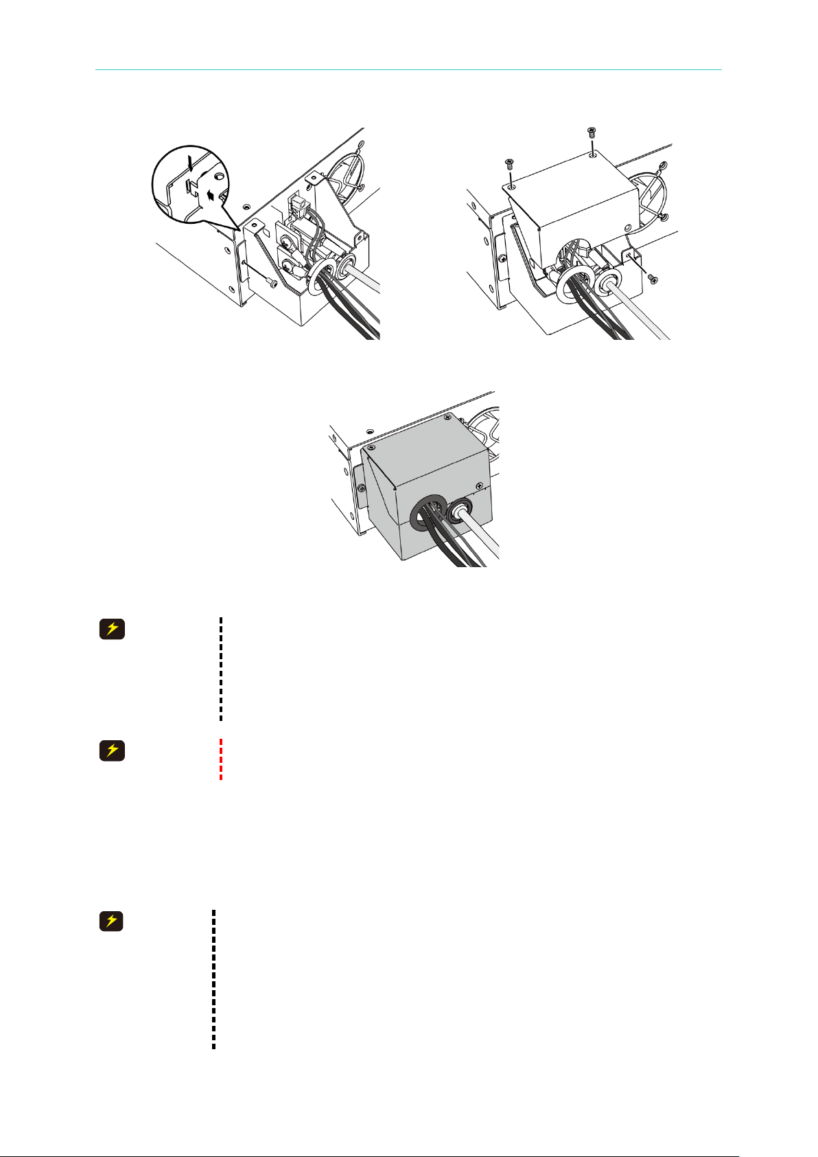
(4) See Figure 2-3 (a), (b) to connect the cables to the 62000H. See Figure 2-5 to connect
the cables to the 62020H-150S. Then perform the following steps:
a. Remove the input terminal safety cover from the rear panel of the DC Power
Supply.
b. Scrape off any coating on the power cable tip (the bare portion is about 1cm) and
use an O type terminal to crimp it. (For the 62020H-150S, the bare portion needs to
be tinned.)
c. Secure the power cable to the input terminal with a Phillips screwdriver with a lock
torque in the 30-40 (kg-cm) range. (For the 62020H-150S, insert the pow er terminal
and use a Phillips screwdriver to secure it.)
d. Lock the safety cover to avoid electric shock.
e. Secure the safety cover latch and safety cover to prevent the cable from falling or
the electric terminal from being exposing.
Page 40

Programmable DC Power Supply (with Solar Array Simulation) 62000H Series
2-4
terminal.
Operating & Programming Manual
(a) (b)
Figure 2-3
Figure 2-4
1. Connect the green or green/yellow metal w ire to the terminal.
2. Connect the black or brown metal wire to the “L1, L2, L3” terminals.
3. Figure 2-5 shows the suggested specification of an O type terminal.
Figure 2-5
4. Connect the white or blue metal wire of the 62020H-150S to the “N”
Page 41
Installation
2-5
5. Connect the black or brown metal wire of the 62020H-150S to the “L”
terminal.
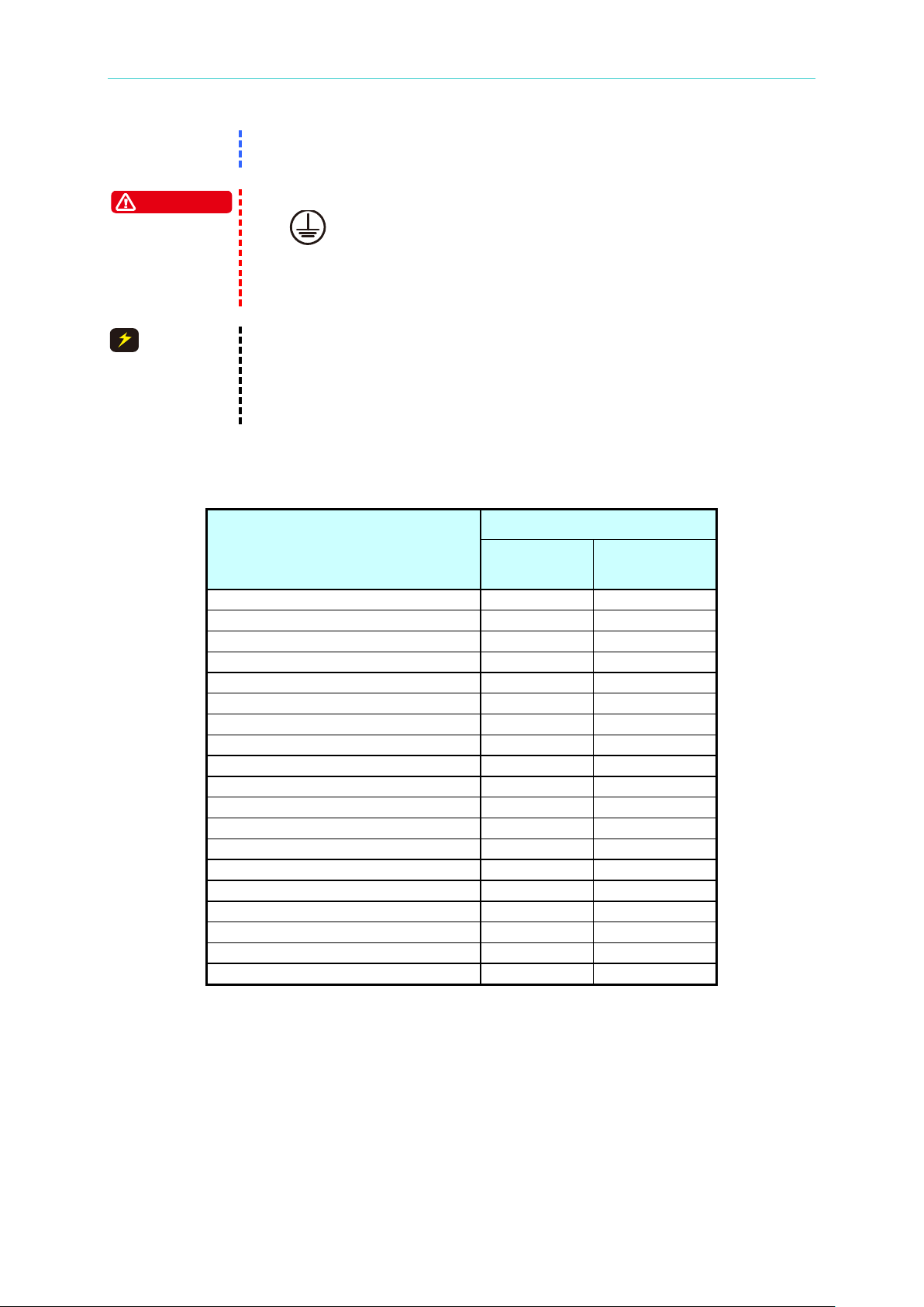
1. To protect the operator, the wire connected to the GND terminal
compliant with local electrical codes.
1. Be sure to select an appropriate withstand voltage cable based on
connect it to the input terminal.
Safe Current (A)
Conductor
Conductor
1.25
15
--
2.0
20
--
3.5
30
--
5.5
40
--
8.0
55
--
14
70
50
22
90
70
30
120
90
38
145
100
50
175
120
80
230
150
100
260
200
125
300
240
150
350
270
200
425
330
250
500
380
325
600
450
400
700
500
500
800
600
WARNING
CAUTION
( ) must be connected to the earth. This DC Power Supply must
be operated with an adequate ground connection.
2. Installation of the power cord must be done by a professional and
the desired input voltage.
2. To ensure operational safety, select a proper current rated
BREAKER for the input power source that switches each phase and
Table 2-1 is a cable specification for PVC (105°C) with the ambient temperature at 30°C.
Table 2-1 PVC (105°C) Cable Specification
Conductor Area
Sectional Area mm2
Copper
Lead
2.4 Remote Sensing
2.4.1 C orr ect Co nne c tion
1. Connect the remote sensing wire to ensure the output voltage equals the set voltage.
The DC Power Supply is able to compensate up to a 4% F.S. line voltage drop.
2. Figure 2-6 shows the correct connection. Use two wires to connect the positive and
negative connectors of the load to the remote sensing connector on the rear panel. The
Page 42

Programmable DC Power Supply (with Solar Array Simulation) 62000H Series
2-6
V = 6 0. 0 0 V I = 1 0. 0 0 _ A O F F
0 . 0 0 0 0 V 0 . 0 0 0 0 A
S E N S E F A U L T 0 . 0 W
S H U T – D N
Operating & Programming Manual
connecting wire diameter must be larger than 30AWG and it’s withstand voltage should
be within the specification.
3. Although remote sensing is able to compensate for a volta ge drop, if the line loss is too
large (see specification) it will cause a protection error as shown in Figure 2-8 indicating it
is unable to compensate for the voltage drop.
4. Connect the remote sensing wire of the 62020H-150S as shown in Figure 2-7.
5. The remote sensing wire needs to be connected to the DC Power Supply local output or
the remote input of the UUT.
Figure 2-6
Figure 2-7
Figure 2-8
Page 43

Installation
2-7
If the power supply remote sense error appears, do the following to reset
3. Restart the Power Supply.
1. If there is voltage on the Power Supply output, do not reverse the
before operating the power supply.
CAUTION
2.4.2 Reverse Connection of Remote Sensing Wire
Polarity
The remote sensing wire polarity must be correct, with the “+” terminal connected to the
“+”output terminal and the “–” terminal connected to the “–” output terminal. If the polarity is
reversed, the output will drop to 0V and the error message “SENSE FAULT” will display as
shown in Figure 2-8.
it:
1. Power off the equipment.
2. Connect the remote sensing wire properly.
Remote sense connection on the supply or the UUT to avoid
damaging the Power Supply.
2. The Remote Sense and local output voltage needs to be less than
10% V_MAX to avoid damaging the Power Supply.
3. The output voltage may overshoot if the Remote sense wire is
disconnected during operation. Be s ure to connect the Remote
sense wire to the DC Power Supply local output or the Load UUT
2.5 Output Connection
The output connector of the 62000H Series DC Power Supply with Solar Array Simulation is
located in the upper middle area on the rear panel and for the 62020H-150S it is on the left
side of the rear panel. The load is connected to the “+” and “–” output terminals.
2.5.1 Rear Panel Output
(1) The output terminal is located in the upper middle area on the rear panel. (For the
62020H-150S, the output terminal is located on the left side of the rear panel.)
(2) The output cable must be rated for 85°C or higher.
(3) To connect the output cables, see Figure 2-9 (a) & (b) for the 62000H and Figure 2-11 (c),
(d), (e), (f) and (g) for the 62020H-150S. Perform the steps below:
a. Scrape off any coating on the power cable tip (the bare portion is about 1cm) and
use an O type terminal to crimp it.
b. Secure the power cable and input terminal with a Phillips screwdriver.
c. Secure the safety cover latch and safety cover to prevent the cable from falling or
the electric terminal from being exposed.
(4) A standard hoop is attached when purchasing the A620028 or A620027 SLAVE model to
hold the current sharing cables as shown in Figure 2-10. Mount it first and then continue
the installation as shown in Figure 2-9.
Page 44

Programmable DC Power Supply (with Solar Array Simulation) 62000H Series
2-8
Operating & Programming Manual
(a) (b)
Figure 2-9
Figure 2-10
(c) (d)
Page 45
2-9
1. The safety cover must be tightly secured to meet the safety
cable when using the device in standalone mode.
62000H Series).
1. To ensure the system’s stability, the cable inductance should not
identified by the sticker labeled 2mH on top of the output cover as
CAUTION
CAUTION
CAUTION
(e) (f)
Installation
(g)
Figure 2-11
requirements.
2. Make sure the wire connected to the load is able to carry the
maximum applied current.
3. There is no need to use the 62020H-150S 9PIN current sharing
Do not exceed the rated output current (different for each model in the
2.5.2 Connecting Wire Specifications
The maximum inductance of the wire connected to the source should be less than 2μH (the
total inductance of two wires afte r tw i sti ng or otherwise bundled, including self-inductance and
mutual inductance).
exceed 2μH. If the UUT input capacitance is too small (less than
100uF), the inductance of the UUT input should be added to the
cable inductance when calculating the total cable inductance. The
maximum inductance of some models, such as the 62150H-1000S
(380/400Vac, 440/480Vac) and the A620028 (380/400Vac,
440/480Vac), can be up to 2mH. The maximum inductance can be
Page 46

Programmable DC Power Supply (with Solar Array Simulation) 62000H Series
2-10
shown in Figure 2-12. Fo r other models, contact your Chroma agent.
2. Be sure to use the proper diameter wire to avoid overheating.
Model
Max. Parallel Capacitance for Output (uF)
62050H-600S
1350
62100H-600S
2700
62150H-600S
4050
62150H-1000S
1350
A620028
1350
A620027
4050
62020H-150S
10000
1. To ensure the system’s stability, the capacitance should not exceed
Be aware of the polarity and withstand voltage when paralleling
capacitance.
CAUTION
Operating & Programming Manual
Figure 2-12
2.5.3 Parallel Capacitance Specifications
The maximum parallel output capacitance varies according to the 62000H Series Models as
shown in Table 2-2.
Table 2-2
the value listed in Table 2-2.
2.
2.5.4 Installing the Handle (62150H for example)
Use M4x 12 flat head screws to secure the handle to the rack mounting kit as shown in Figure
2-13.
Page 47

Installation
2-11
S E L F T E S T . . .
M O D E L : 6 2 1 5 0 H – 6 0 0 S S E R I A L N O :1
D I S P L A Y < O K >
F I R M W A R Y 0 0 . 0 7, D E C 1 7 2 0 0 9
F P G A 0 0 . 0 0 B
W A I T . . .
Figure 2-13 Installing the Handle
2.6 Power-On Procedure
Plug in the power cord and turn ON the power switch on the front panel. The DC Power
Supply will run a series of self-tests. The VFD on the fr ont panel will light up and display the
following:
Figure 2-14
The DC Power Supply will run self-tests for memory, data, and communication. Once the
self-tests are completed, the Model No., Serial No., and an “OK” prompt will display on the
screen if all tests completed successfully. When the self-test is done the display shows:
Figure 2-15
Page 48

Programmable DC Power Supply (with Solar Array Simulation) 62000H Series
2-12
V = 0. 0 0_ V I = 0. 0 0 A O F F
0 . 0 0 0 0 V 0 . 0 0 0 0 A
0 . 0 W
before powering ON again.
Before turning on the instrument, all protective grounding terminals,
resulting in injury to personnel.
WARNING
WARNING
Operating & Programming Manual
When the memory, data, and communication self tests are done, the scree n goes to the M A IN
PAGE automatically, as shown below:
Figure 2-16
The DC Power Supply internal circuits may not be able to reset if it is
powered off and on quickly. Wait at least 3 seconds after powering OFF
extension cords, and devices must be connected to an earth ground. A
potential electric shock hazard may exist with any incomplete grounding,
Page 49

Manual Operation
3-1
If the operation mode is not saved before the instrument is powered off,
the operation mode is manual (default) the next time it is powered on
VOLT
9
ON/OFF
VOLT
ON/OFF
V = 0. 0 0_ V I = 0. 0 0 A O F F
0 . 0 0 0 0 V 0 . 0 0 0 0 A
0 . 0 W
1
ENTER
3. Manual Operation
3.1 Introduction
The DC Power Supply can be operated manually or remotely via a GPIB/ETHERNET (option),
USB, RS-232/RS-485, or APG interface as described in Chapter 5 and section 3.3.1.1.
Manual operation using the front panel keyboard or rotary knobs to input the data is described
in this chapter.
3.2 Setting Voltage & Current
There are two ways to set the output voltage (CV MODE) as shown in Figure 3-1:
Method 1:
1. Press “
2. Use the numeric keys ( the voltage setting or turn the “Rotary” (
3. Press “
setting must be larger than the load current; otherwise, the output voltage will not be
equal to the set voltage.)
Method 2:
1. Press “
”, the cursor for V on MAIN PAGE blinks.
) to set the value and press “ ” to complete
) knob to adjust the set value.
” to output the set voltage. (To keep the output in CV mode the current
”, the cursor for V on MAIN PAGE blinks.
2. When using the Rotary knob (
to move the cursor to each individual digit, then turning the rotary knob to increase or
decrease the value.
3. Press “
setting must be larger than the load current; otherwise, the output voltage will not be
equal to the set voltage.)
” to output the set voltage. (To keep the output in CV mode the current
) for setting, the “ ”, “ ” keys can be used
Figure 3-1
Page 50

Programmable DC Power Supply (with Solar Array Simulation) 62000H Series
3-2
CURR
V
= 0
.
0 0 V I
= 0
.
0 0
_
A O F F
0 . 0 0 0 0 V 0 . 0 0 0 0 A
0 . 0 W
1. System Setup
:
Sets various system parameters including GPIB address.
2. Output Setup
:
Sets various output parameters including voltage/current slew rate etc.
3. Series/Parallel
:
Sets the parameters for series or parallel mode.
4. Display
:
Sets the parameter arrangement on panel.
5. Protection
:
Sets the parameters for each protection function.
6. Factory Setting
:
Sets the production information and settings.
7. Calibration
:
Calibrates the DC Power Supply.
8. Remote Setting
:
Sets the system parameters for GPIB address etc.
9. Output Mode
:
Selects CV/CC mode or the output mode with IV function.
CONF
C H O I C E = S Y S T E M S E T U P [ C O N F I G ]
1. S Y S T E M S E T U P 5. P R O T E C T I O N
2. O U T P U T S E T U P 6. F A C T O R Y S E T T I N G
3. S E R I E S / P A R A L L E L 7. C A L I B R A T I O N
4. D I S P L A Y 8. R E M O T E S E T U P
9. O U T P U T M O D E
Operating & Programming Manual
To set the current (CC MODE):
Press “
3-2. (To keep the output in CC mode the voltage setting must be larger than the load voltage;
otherwise, the output current will not be equal to the set current.)
”. The remaining steps are the same as the voltage settings, as shown in Figure
Figure 3-2
3.3 Setting Configuration
The configuration setting function allows users to set the system functions for the DC Power
Supply. The system functions that can be set during configuration are:
To set the configuration:
Press “
” to enter into the config setting screen as shown in Figure 3-3.
Figure 3-3
Page 51

3-3
1.
1
9
2. Press “
VOLT
” or “
CURR
” in any page to return to the MAIN PAGE.
ENTER
EXIT
EXIT
Use the numeric keys (
set.
2.
Press “ ” to conf irm.
3.
Press “ ” to return to the MAIN PAGE.
-
) or the “Rotary” ( ) knob to selec t the i tem to be
1. To cancel the setting, press “ ” to return to the MAIN PAGE.
Figure 3-4 shows the tree structure of CONFIG PAGE.
Manual Operation
Page 52

Programmable DC Power Supply (with Solar Array Simulation) 62000H Series
3-4
Operating & Programming Manual
Figure 3-4
Page 53

3-5
3.3.1 SYSTEM SETUP
1
[
S Y S T E M S E T U P]
A P G V S E T
=
N O N E _
A P G I S E T
= N O N E
A P G V M E A S =
N O N E
A P G I M E A S
= N O N E
B U Z Z E R = O N
P O W E R O N S T A T U S = D E F A U L T
[S Y S T E M S E T U P
]
A P G V S E T
=
N O N E _
A P G I S E T
=
N O N E
A P G V M E A S =
N O N E
A P G I M E A S
= N O N E
B U Z Z E R
= O N
P O W E R O N S T A T U S =
D E F A U L T
ENTER
0
4
ENTER
Manual Operation
1. In the Config setup page, press “
Figure 3-5. Use the “
”, “ ” keys to move the cursor to the desired
” then “ ” to display the screen shown in
selection.
Figure 3-5
3.3.1.1 APG
The Analog Programming interface (APG) performs the following two functions: 1. uses the
analog signal control panel to set the value and 2. uses the analog si gnal to indicate the panel
measurement. The values for set and measure can be set separately as described below.
1. Use the “
Figure 3-6.
”, “ ” keys to move the cursor to the column to be set as shown in
Figure 3-6
2. For APG VSET, use the numeric keys - or the “Rotary” (
the mode. There are 5 selections for APG VSET: NONE / Vref(0-5V) /Vref(0-10V) /
Iref(4-20mA)/ Rref(0-5KOhm), where:
NONE: means not using the programming function.
Vref(0-5V): means using the external voltage source as the programming setting.
Vref(0-10V): means using the external voltage source as the programming setting.
Iref(4-20mA): means using the external voltage current source as the programming
setting.
Rref(0-5KOhm): means using the external resistance as the programming setting.
3. Press “ ” to confirm.
) knob to set
Page 54
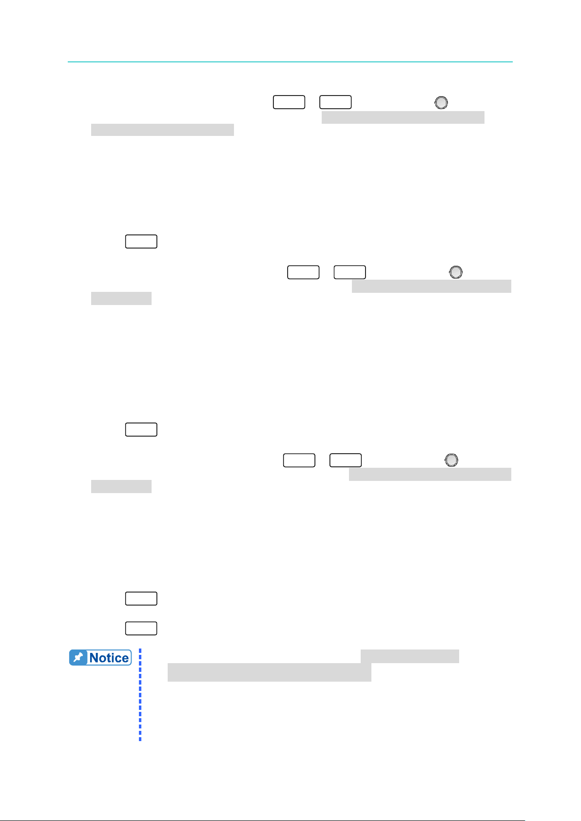
Programmable DC Power Supply (with Solar Array Simulation) 62000H Series
3-6
EXIT
1.
APG VSET/APG ISET has 5 selections: NONE / Vref(0-5V) /
c. Selecting Iref=4-20mA means the DC Power Supply’s output 0V -
0
4
ENTER
0
3
ENTER
0
3
ENTER
Operating & Programming Manual
4. For APG ISET, use the numeric keys - or the “Rotary” ( ) knob to set
the mode. There are 5 selections for APG ISET: NONE / Vref(0-5V) / Vref(0-10V) /
Iref(4-20mA) / Rref(0-5KOhm), where:
NONE: means not using the programming function.
Vref (0-5V): means using the external voltage source as the programming setting.
Vref (0-10V): means using the external voltage source as the programming setting.
Iref (4-20mA): means using the external voltage current source as the programming
setting.
Rref(0-5KOhm): means using the external resistance as the programming setting.
5. Press “ ” to confirm.
6. For APG VMEAS, use the numeric keys - or the “Rotary” ( ) knob to
set the mode. There are 4 selections for APG VMEAS: NONE / Vref(0-5V) / Vref(0-10V) /
Iref(4-20mA), where:
NONE: means not using the measurement function.
Vref (0-5V): means using the power supply output voltage source as the measurement
result.
Vref (0-10V): means using the power supply output voltage source as the measurement
result.
Iref (4-20mA): means using the power supply output current source as the measurement
result.
7. Press “ ” to conf irm.
8. For APG I MEAS, use the numeric keys - or the “Rotary” ( ) knob to
set the mode. There are 4 selections for APG IMEAS: NONE / Vref( 0 -5V) / Vref(0-10V) /
Iref(4-20mA), where:
NONE: means not using the measurement function.
Vref (0-5V): means using the power supply output voltage source as the measurement
result.
Vref (0-10V): means using the power supply output voltage source as the measurement
result.
Iref (4-20mA): means using the power supply output current source as the
9. Press “ ” to confirm.
10. Press “
” to ret urn to the MAIN PAGE.
Vref(0-10V) / Iref(4-20mA)/ Rref(0-5KOhm), where
a. Selecting Vref=5V means the DC Power Supply’s output 0V -
600V/0A ~ 25A will map to 0-5V as shown in Figure 3-7(a).
b. Selecting Vref=10V means the DC Power Supply’s output 0V -
600V/0A ~ 25A will map to 0-10V as shown in Figure 3-7 (b).
:
Page 55

3-7
600V/0A ~ 25A will map to 4-20mA as shown in Figure 3-7 (c).
d. Selecting Vref=5KOhm means the DC Power Supply’s output 0V -
DC SOURCE SET
600V/25A
APG INPUT 5V
DC SOURCE SET
APG INPUT 10V
600V/25A
DC SOURCE SET
600V
/25A
APG INPUT 4 ~ 20mA
DC SOURCE SET
APG INPUT 5KOhm
600V/25
A
3-8 (c).
600V/0A ~ 25A will map to 0-5KOhm as shown in Figure 3-7 (d).
(a) (b)
Manual Operation
(c) (d)
Figure 3-7
2.
APG VMEAS/APG IMEAS has 4 selections: NONE / Vref(0-5V ) /
Vref(0-10V) / Ir ef (4-20mA) where:
a. Selecting Vref=5V means the DC Power Supply’s measurement
output 0 - 600V/0A ~ 25A will m ap to 0-5V as shown in Figure 3-8
b. Selecting Vref=10V means the DC Power Supply’s measurement
output 0 - 600V/0A ~ 25A will map to 0-10V as shown in Figure 3-8
(b).
c. Selecting Iref=4-20mA means the DC Power Supply’s measurement
output 0 - 600V/0A ~ 25A will map to 4mA-20mA as shown in
(a).
Figure
Page 56

Programmable DC Power Supply (with Solar Array Simulation) 62000H Series
3-8
DC SOURCE MEAS
600V/25A
APG OUTPUT 5V
DC SOURCE MEAS
APG OUTPUT 10V
600V/25A
DC SOURCE MEAS
APG OUTPUT 4
mA~20mA
600V/25A
sufficient to avoid damaging the resistor.
1
14
13
25
Operating & Programming Manual
(a) (b)
(c)
Figure 3-8
3. Calibrate the APG settings and measurements before using APG
control.
4. When setting the APG VMEAS/APG IMEAS to Iref(4-20mA) mode,
ensure the series resistance does not exceed 500Ω so the DC Power
Supply outputs the correct values. Ensure the resistor wattage is
3.3.1.1.1 Pin Assignment of the APG Control Interface
The APG interface is a bi-directional interface utilizing analog signals. The connector is
located on the rear panel and its pin assignments are shown in Figure 3-9, Figure 3-10, and
Appendix A.
Figure 3-9
Page 57

Manual Operation
3-9
5 18 6 19
1
+12VAPI API GND AVO_SET_R AIO_SET_R AVO_SET_C AIO_SET_C AVO_SET_V AIO_SET_V
AVO_MEAS_C AIO_MEAS_C AVO_MEAS_V AIO_MEAS_V
14 2 15 3
16 4
17
- +
- +
sensing
sensing
sensing
sensing
APG Interface pin definitions:
Figure 3-10
1. Auxiliary power Vcc: outputs +12Vdc with a maximum output current of 10mA (output
port).
2. Voltage programming: inputs the resistance (0-5K Ohm) between this pin and APIGND to
linearly control the output voltage (CV mode).
3. Voltage programming: inputs the analog current (4-20mA) between this pin and APIGND
to linearly control the output voltage (CV mode).
4. Voltage programming: inputs the analog voltage (0-5Vdc or 0-10Vdc) between this pin
and APIGND to linearly control the output voltage (CV mode).
5. Voltage measurement: outputs the analog curre nt (4mA-20mA) for monitoring.
6. Voltage measurement: outputs the analog voltage (0-5V or 0-10V) for monitoring.
14. APIGND: This contact is the reference potential of the APG interface. The potential is
isolated between the APG and chassis with a maximum voltage differential of 70Vdc.
15. Current programming: inputs the resistance (0-5K Ohm) between this pin and APIGND to
linearly control the output current (CC mode).
16. Current programming: inputs the analog current (4-20mA) between this pin and APIGND
to linearly control the output current (CC mode).
Page 58

Programmable DC Power Supply (with Solar Array Simulation) 62000H Series
3-10
[
S Y S T E M S E T U P
]
A P G V S E T
=
N O N E _
A P G I S E T
=
N O N E
A P G V M E A S =
N O N E
A P G I M E A S
=
N O N E
B U Z Z E R
=
O N
P O W E R O N S T A T U S
=
D E F A U L T
1
1. The BUZZER has two options: ON / OFF. (Default is ON).
4. When the BUZZ ER is s et to OFF it will not beep in any situation.
0
ENTER
EXIT
Operating & Programming Manual
17. Current programming: inputs the analog voltage (0-10Vdc or 0-5Vdc) between this pin
and APIGND to linearly control the output current (CC mode).
18. Current measurement: outputs the analog current (4mA-20mA) for monitoring.
19. Current measurement: outputs the analog voltage (0-5V or 0-10V) for monitoring.
3.3.1.2 BUZZER
The buzzer sounds when the keys or the rotary knob on the front panel are pressed or turned.
It can be turned off if an audio response is not necessary. (The default is ON.)
1.
Use the “ ”, “ ” keys to move the cursor to the column to be set as shown in
Figure 3-11.
Figure 3-11
2.
Use the numeric keys ( mode.
) or the “Rotary”( ) knob to select “ON” or “OFF”
3. Press “ ” to conf irm.
4.
Press “ ” to return to the MAIN PAGE.
2. When the BUZZER is set to ON, pressing any key or turning the
rotary knob will sound the buzzer.
3. When the BUZZER is set to ON, the BUZZER will beep continuously
if a system protection error occurs.
3.3.1.3 POWER ON STATUS
Automatically loads the default output status when the unit is powered ON.
1.
Use the “ ”, “ ” keys to move the cursor to the column to be set as shown in
Figure 3-12.
Page 59

Manual Operation
3-11
[S Y S T E M S E T U P
]
A P G V S E T
=
N O N E
A P G I S E T
=
N O N E
A P G V M E A S
= N O N E
A P G I M E A S
= N O N E
B U Z Z E R
= O N _
P O W E R O N S T A T U S
=
D E F A U L T
0
2
Figure 3-12
2.
Press “ ” or “ ” or use the ““Rotary” ( ) knob to set the value.
POWER ON STATUS has three options: DEFAULT / LAST TURN OFF STATUS / USER
DEFINITION.
When set to DEFAULT, the output state is set to: V = 0.00V ; I = 0.00A ; OUTPUT = OFF.
When set to LAST TURN OFF STATUS, the instrument will store the last voltage, current
and output state settings before powering off and they will be restored on power ON.
Ex.: In Figure 3-13, the voltage setting is 60.00V, current setting is 10.00A and output
setting is ON. When it powers on again, the instrument will restore the previous state by
setting the voltage to 60.00V, current to 10.00A and output to ON.
Figure 3-13
When set to USER DE FINITION, a line will display beneat h t he POWER ON STATUS
line as shown in
Figure 3-14 for the user to set the default power-on state including
voltage (V_SET), current (I_SET) and OUTPUT=ON/OFF.
Page 60

Programmable DC Power Supply (with Solar Array Simulation) 62000H Series
3-12
[S Y S T E M S E T U P
]
A P G V S E T
=
N O N E
A P G I S E T
=
N O N E
A P G V M E A S = N O N E
A P G I M E A S
= N O N E
B U Z Z E R
= O N
P O W E R O N S T A T E S
=
U S E R D E F I N I T I O N
_
V = 6 0
.
0 0 V
=
1 0
.
0 0 A O U T P U T
= O F F
EXIT
EXIT
The values in Figure 3-15 are t he default settings of the 62150H-600S.
ENTER
2
ENTER
Operating & Programming Manual
Figure 3-14
3. Press “ ” to conf irm.
4. Press “
” to return to the MAIN PAGE.
3.3.2 OUTPUT SETUP
1. In the Config Setup page, press “ ” then “ ” to enter into the Output Setup
screen as shown in Figure 3-15.
2. Press the “
3. Press “
”, “ ” keys to move the cursor to the column to be set.
” to return to the MAIN PAGE.
Figure 3-15
Page 61

Manual Operation
3-13
0
VOLT
EXIT
9
ENTER
3.3.2.1 VOLTAGE LIMIT SETTING
1. Use the “ ”, “ ” keys to move the cursor to the column to be set as shown in
Figure 3-16.
2. Use the numeric keys (
Use this option to narrow down the range by setting the MIN and MAX values. When
“
within the range of [MIN value ≤ user-defined value ≤ MAX value]. For example, if the V
LIMIT is set to MAX=100V, MIN=20V and the setting exceeds the output voltage set by
the user (e.g. 110V), the BUZZER will beep one time (if the BUZZER is set to ON) and
the main screen will automatically prompt a warning message as shown in Figure 3-17
below.
Figure 3-16
- ) or the “Rotary” ( ) knob to set the value.
” is pressed to set the output voltage, the DC Power Supply sets the voltage
3. Press “ ” to confirm.
4. Press “
” to return to the MAIN PAGE.
Figure 3-17
Page 62
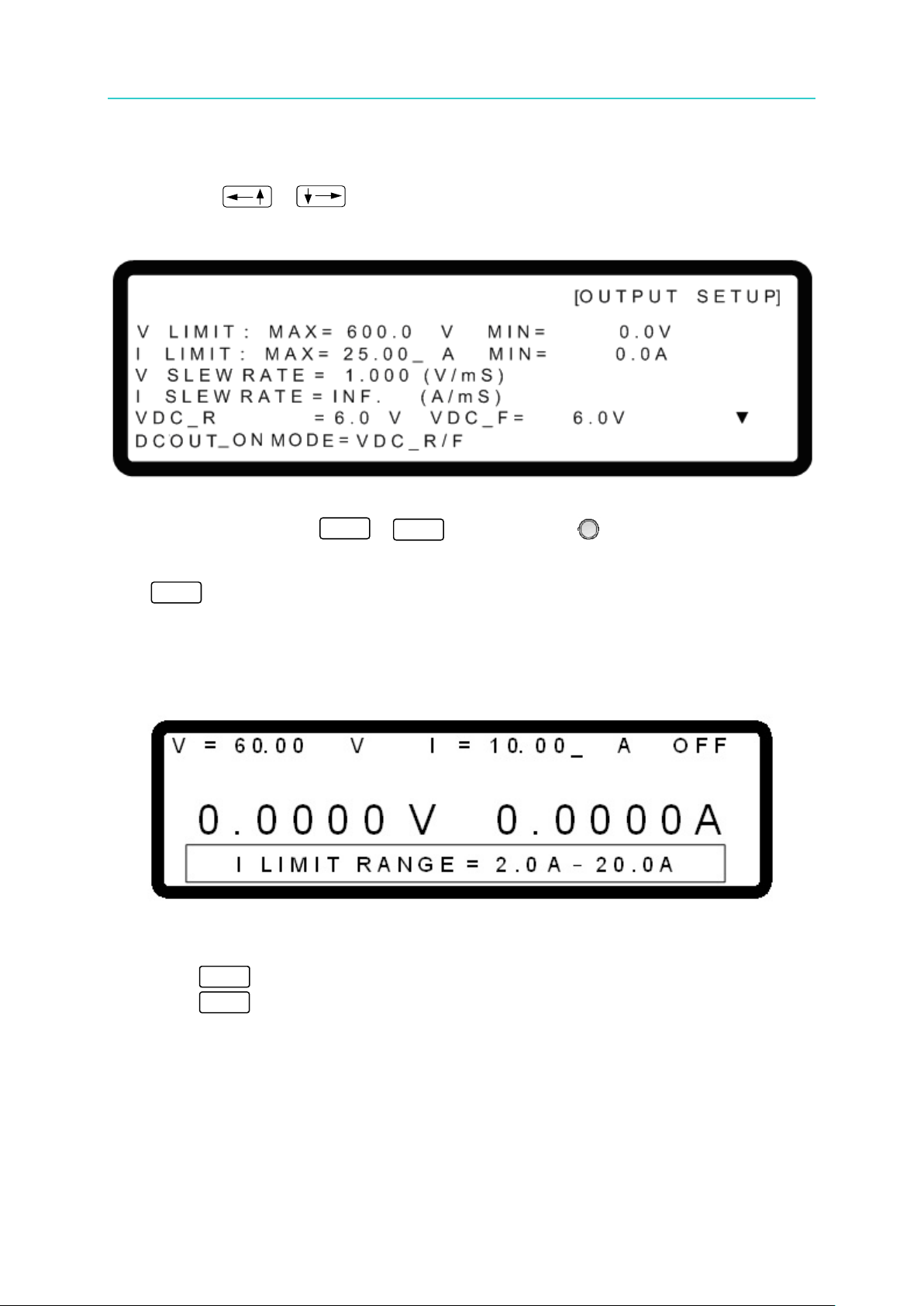
Programmable DC Power Supply (with Solar Array Simulation) 62000H Series
3-14
0
CURR
EXIT
9
ENTER
Operating & Programming Manual
3.3.2.2 CURRENT LIMIT SETTING
1. Use the “ ”, “ ” keys to move the cursor to the column to be set as shown in
Figure 3-18.
2. Use the numeric keys (
Use this option to narrow down the range by setting the MIN and MAX values. When
“
the range of [MIN value ≤ user-defined value ≤ MAX value]. For example, if the I LIMIT is
set to MAX=20A, MIN=2A and the setting exceeds the output current set by the user (e.g.,
21A), the BUZZER will beep one time (if BUZZER is set to ON) and the main screen will
automatically prompt a warning message as shown in Figure 3-19 below.
Figure 3-18
- ) or the “Rotary” ( ) knob to set the value.
” is pressed to set the output current, the DC Power Supply sets the current within
3. Press “ ” to confirm.
4. Press “
” to return to the MAIN PAGE.
Figure 3-19
Page 63

Manual Operation
3-15
0
Vo
Time(mS)
ΔT
ΔV
V
SR
T
∆
=
∆
EXIT
The minimum transient time is (ΔT) = 0.5 ms.
9
ENTER
3.3.2.3 VOLTAGE SLEW RATE
1. Use the “ ”, “ ” keys to move the cursor to the column to be set as shown in
Figure 3-20.
2. Use the numeric keys (
The output voltage slew rate of the DC Power Supply is set as shown in Figure 3-21. The
maximum input Slew Rate is 20V/mS and the minimum is 0.001V/mS. The output of the
DC Power Supply will follow the rising s lew rate to the set output voltage while the falling
slew rate is limited by the load.
Figure 3-20
- ) or the “Rotary” ( ) knob to set the value.
3. Press “ ” to confirm.
4. Press “
” to return to the MAIN PAGE.
Figure 3-21
Page 64

Programmable DC Power Supply (with Solar Array Simulation) 62000H Series
3-16
0
ΔT
ΔI
I
SR
T
∆
=
∆
Time(mS)
Io
EXIT
9
ENTER
Operating & Programming Manual
3.3.2.4 CURRENT SLEW RATE SETTING
1. Use the “ ”, “ ” keys to move the cursor to the column to be set.
Figure 3-22
2. Use the numeric keys (
- ) or the “Rotary” ( ) knob to set the value.
The output current slew rate of the DC Power Supply is set as shown in Figure 3-23. The
maximum input Slew Rate is 0.1A/mS and the minimum is 0.003A/mS. If the input is
larger than 0.3A/mS, the current Slew Rate will be set to INF. and will change with the
maximum slew rate (near infinite). The output of the DC Power Supply will follow the
rising slew rate to the set output current.
Figure 3-23
3. Press “ ” to confirm.
4. Press “
” to return to the MAIN PAGE.
Page 65

Manual Operation
3-17
VDC_R
VDC_F
t
VO
DC_ON
0
9
3.3.2.5 Setting DC_ON
The DCOUT_ON signal on the ANALOG INTERFACE can be set to follow the rising and
falling edges of the voltage waveform or the positi on of the OUTPUT but ton on the front panel .
If the DCOUT_ON signal is set to VDC_R/F and the voltage is over VDC_R, pin10
DCOUT_ON on the ANALOG INTERF ACE will g o HIG H. If the voltage is lower than VDC_F,
pin10 DCOUT_ON on the ANALOG INTERFACE will go LOW. If the DCOUT_ON signal is set
to VDC_ON/OFF, the signal will follow the position of the OUTPUT button on the front panel,
as shown in Figure 3-24:
Figure 3-24
Set DC_ON as described below:
1. Method 1: Use the “
as shown in Figure 3-25.
2. Use the numeric keys (
lower limit is 1%Vmax and the upper limit is 99%Vmax, e.g., the lower limit of DC_ON is
6V and the upper limit is 594V for the 62150H-600S.
”, “ keys to move the cursor to the column to be set
Figure 3-25
- ) or the “Rotary ” ( ) knob to set the values. The
3. Method 2: Use the “
as shown in Figure 3-26.
”, “ ” keys to move the cursor to the column to be set
Page 66

Programmable DC Power Supply (with Solar Array Simulation) 62000H Series
3-18
0
1
[O U T P U T S E T U P]
I V C U R V E P A R A M E T E R:
C O N T R O L M O D E = C C M O D E _
I N P U T F I L T E R = 1 0 0 0 Hz
O U T P U T S P E E D = M I D D L E
S E T T I N G M A R G I N = 3 %
▲
Operating & Programming Manual
Figure 3-26
4. Use the numeric keys (
-
) or the “Rotary” ( ) knob to set DCOUT_ON
MODE to ON/OFF, which causes pin10 on the ANALOG INTERFACE to follow the
OUTPUT button on the front panel.
3.3.2.6 Setting IV CURVE Parameters
IV Curve related parameters such as CONTROL MODE, INPUT FILTER, OUTPUT SPEED
and SETTING MARGIN can be modified in the IV CURVE PARAMETER as shown in Figure
3-27. The IV CURVE PARAMETER settings adjust the IV Curve algorithm in Table mode,
SAS mode, and IV Pro gram.
Figure 3-27
3.3.2.6.1 Setting CONTROL MODE
When the DC Power Supply is operating in IV mode, the CONTROL MODE will affect the IV
Curve settings and the measured object. When set to CC mode, the DC Power Supply will
measure the output voltage and use the IV Curve mapped current as the control current to
draw the IV Curve shown in Figure 3-28(a). If the CONTROL MODE is set to CV mode, the
DC Power Supply will measure the output current and use the IV Curve mapped voltage as
the control voltage to draw the IV Curve shown in Figure 3-28(b).
Page 67

3-19
Figure 3-28
0
EXIT
0
EXIT
Voc
Isc
V1
Iset1
V2
Iset2
(a) CC Mode
Voc
Isc
Vset1
I1
Vset2
I2
(b) CV Mode
Voc
Isc
V1
Iset1
V2
Iset2
Voc
Isc
V1
Iset1
V2
Iset2
(a) CC Mode
Voc
Isc
Vset1
I1
Vset2
I2
(b) CV Mode
1
ENTER
[O U T P U T S E T U P]
I V C U R V E P A R A M E T E R:
C O N T R O L M O D E = C C M O D E
I N P U T F I L T E R = 1 0 0 0 Hz
_
O U T P U T S P E E D = M I D D L E
S E T T I N G M A R G I N = 3 %
▲
9
ENTER
Set the CONTROL MODE as described below:
Manual Operation
1. Use the “
”, “ ” keys to move the cursor to the column to be set as shown in
Figure 3-27.
2. Use the numeric keys (
- ) or the “Rotary” ( ) knob to select either CC
MODE or CV MODE. The default setting is CC MODE.
3. Press “ ” to confirm.
4. Press “
” to return to the MAIN PAGE.
3.3.2.6.2 Se tting I NPUT FILTER
INPUT FILTER filters the measured signals for the IV Curve calculation used in IV mode. For
example, if the measured voltage waveform has 20 kHz ripple then setting the INPUT FILTER
to 1kHz can eliminate the 20 kHz ripple component.
1. Use the “
Figure 3-29.
”, “ ” keys to move the cursor to the column to be set as shown in
Figure 3-29
2. Use the numeric keys (
FILTER frequency. The setting range is 1-3125Hz and the default is 1000Hz.
3. Press “ ” to confirm.
4. Press “
- ) or the “Rotary” ( ) knob to set the INPUT
” to return to the MAIN PAGE.
Page 68

Programmable DC Power Supply (with Solar Array Simulation) 62000H Series
3-20
0
EXIT
[
O U T P U T S E T U P]
I V C U R V E P A R A M E T E R
:
C O N T R O L M O D E = C C M O D E
I N P U T F I L T E R =
1 0 0 0 Hz
O U T P U T S P E E D
= M I D D L E
_
S E T T I N G M A R G I N = 3 %
▲
2
ENTER
[O U T P U T S E T U P]
I V C U R V E P A R A M E T E R:
C O N T R O L M O D E = C C M O D E
I N P U T F I L T E R = 1 0 0 0 Hz
O U T P U T S P E E D
= M I D D L E
S E T T I N G M A R G I N = 3 % _
▲
Operating & Programming Manual
3.3.2.6.3 Setting OUTPUT SPEED
OUTPUT SPEED sets the output response speed of the IV Curve to FAST, MIDDLE or SLOW.
The sequence for the output response speed setting is FAST > MIDDLE > SLOW.
1. Use the “
”, “ ” keys to move the cursor to the column to be set as shown in
Figure 3-30.
2. Use the numeric keys (
SPEED. The default is MIDDLE.
3. Press “ ” to confirm.
4. Press “
” to return to the MAIN PAGE.
Figure 3-30
- ) or the “Rotary” ( ) knob to set the OUTPUT
3.3.2.6.4 Setting MARGIN
SETTING MARGIN sets the margin for non-control settings in the IV Curve. For example,
when set to CC mode, the non-control item is the voltage setting and when set to CV mode it
is the current setting. To ensure the control mode remains in a fixed mode, the setting must be
larger than 3%. As shown in Figure 3-28(a), the voltage measurement is V1 so the control
item is the current setting, Iset1, instead of Vset1. When SETTING MARGIN is set to 3%, the
Vset1=1.03*V1.
1. Use the “
Figure 3-31.
”, “ ” keys to move the cursor to the column to be set as shown in
Figure 3-31
Page 69

Manual Operation
3-21
0
EXIT
1. Series/Parallel cannot be used at the same time. A620028 and
62000H Series
Simulation
Serial
Parallel
62150H-600S
2
1200
10
250
62150H-1000S
2
1200
10
150
62020H-150S
2
250
10
400
Contact Chroma’s service unit for a firmware upgrade.
9
ENTER
2. Use the numeric keys (
- ) or the “Rotary” ( ) knob to set the rang e of
SETTING MARGIN. The default is 3%.
3. Press “ ” to confirm.
4. Press “
” to return to the MAIN PAGE.
3.3.3 SERIES/PARALLEL
62000H Series DC Power Supplies with Solar Array Simulation may be connected in series or
parallel when in the CV/CC MODE. The maximum voltage is 1200V if connected in series and
the maximum current is 250A if connected in parallel. When the IV curve function is enabled
in the TABLE Mode, SAS Mode or IV PROGRAM Mode, only parallel connections are
supported (no series connections).
A620027 models only support parallel connections.
2. The maximum output voltage or current is 1200V or 250A when
operating the 62000H Series with Solar Array Simulation in series or
parallel. Table 3-1 shows the values for the 62xxxH-xxxS models.
Table 3-1
Model with
Solar Array
Max.
Devices
Max. Output
Voltage (V)
3. Model types cannot be mixed when operating in Series/Parallel.
4. Insure the breaker capacity is sufficient and the earth grounding wire
is grounded to earth ground when connecting in series/parallel.
5. When more than 5 devices are to be paralleled, contact the Service
Center or CHROMA agent for connection instructions.
6. Stack the DC Power Supplies vertically for parallel connection. The
standard CURRENT SHARING ca b le cannot be used if the devices
are placed horizontally in the parallel configuration; an optional
CURRENT SHARING (100CM) cable is required. Contact the
CHROMA Service Center or local agent for further information. No
more than 2 units may be paralleled when placed horizontally. .
7. Firmware versions 2.00 and above are not backward compatible.
Be sure to upgrade the firmware version from 1.XX to 2.00 when
connecting to a device with firmware version 2.00 for series use.
Max.
Devices
Max. Output
Current (A)
Page 70

Programmable DC Power Supply (with Solar Array Simulation) 62000H Series
3-22
CURRENT
SHARING
CURRENT
SHARING
1 #
2 #
[ SYSTEM BUS]
[ SYSTEM BUS]
SVO+
VO+
VO
SVO
SVO+
VO+
VO-
SVO
DUT
SVO+
VO+
VO
SVO
SVO+
VO+
VO -
SVO
DUT
62150H-600S
62150H-600S
--
--
--
+
-
SVO+
VO+
VOSVO-
SVO+
VO+
VOSVO-
SVO+
VO+
VOSVO-
SVO+
VO+
VOSVO-
SVO+
VO+
VOSVO-
DUT
SVO+
VO+
VOSVO-
SVO+
VO+
VOSVO-
SVO+
VO+
VOSVO-
SVO+
VO+
VOSVO-
SVO+
VO+
VOSVO-
DUT
62150H-600S
62150H-600S
62150H-600S
62150H-600S
62150H-600S
+
-
Operating & Programming Manual
3.3.3.1 Connecting Series/ P ar a llel Output Cables
Figure 3-32 and Figure 3-33 show how to connect the serial and parallel output cables.
Figure 3-32
Figure 3-33
3.3.3.2 Assembling Seri es/ P ar a llel Communication Interface
1. When the DC Power Supplies are connected in series, the SYSTEM BUS connectors on
the rear panel must be connected as shown in Figure 3-34(a.). For the 62020H-150S,
connect the cables as shown in Figure 3-34(b).
(a) (b)
Figure 3-34
Page 71

Manual Operation
3-23
1. The A620028 and A620027 SLAVE models only work when the
other devices for communication.
CURRENT
SHARING
CURRENT
SHARING
CURRENT
SHARING
CURRENT
SHARING
1 #
2 #
10 #
9#
[ SYSTEM BUS]
[ SYSTEM BUS]
[ SYSTEM BUS]
[ SYSTEM BUS]
2. When the DC Power Supplies are connected in parallel, both the SYSTEM BUS and
CURRENT SHARING connectors must be connected as shown in Figure 3-35 (a) [and
Figure 3-35 (b) for the 62020H-150S]. For the A620028 and A620027 the MASTER unit
and ANALOG must be connected as shown in Figure 3-36.
MASTER firmware version is 1.30 or above. If a firmware upgrade is
required, contact Chroma.
2. The A620028 and A620027 SLAVE models have a 1 to 2 ANALOG
communication cable labeled “SLAVE”. This standard accessory is
for A620028 and A620027 use only. The other 1 to 2 A NALO G cable
labeled “MASTER” connects the MASTER side with the A620028
and A620027 as shown in Figure 3-36 (this cable is optional).
3. Plug in the 62020H-150S SYSTME BUS CABLE connector labeled
“REAL” to the device rear panel. See Figure 3-35
(b) for connecting
(a) (b)
Figure 3-35
Page 72

Programmable DC Power Supply (with Solar Array Simulation) 62000H Series
3-24
1. Each DC Power Supply has two RS485 female interface connectors.
path as shown in Figure 3-36.
1. The DC Power Supply could malfunction or be damaged if the
mode.
CAUTION
Operating & Programming Manual
Figure 3-36
They must be connected for series or parallel operation. There is
no difference between left and right; just connect one after another
as shown by the solid line in
62020H-150S, connect the 15P 1 to 2 cable labeled “REAL” to the
rear panel; also connect the two cables as shown in Figure 3-34 or
Figure 3-35. The maximum length for the communication cable is 7.2
meters. Exceeding the length limit may result in unstable
operation.
2. Each DC Power Supply has two CURRENT SHARING connecting
terminals. Connect the output terminal of the first Power Supply to
the input terminal of the second Power Supply and so forth as shown
by the dotted lines in Figure 3-35. For the 62020H-150S, connect the
9P 1 to 2 cable labeled “REAL” to the re ar panel; also connect the
two cables as shown in Figure 3-35. Be sure to us e the CURR E NT
SHARING communication cable provided by CHROMA. The
maximum length for the CURRENT SHARING cable is 3.4 meters.
Exceeding the length limit may result in unstable operation.
3. The CURRENT SHARING communication cable must be securely
connected during parallel operation or it may result in unstable
operation.
4. When the A620028 and A620027 are connected to the MASTER
unit, install a Terminator on the last SYSTEM BUS of the parallel
Figure 3-34 or Figure 3-35. For the
CURRENT SHARING cable is connected incorrectly when in parallel
Page 73

Manual Operation
3-25
malfunction or damage the unit if they remain connected.
Set the SLAVE first and then the MASTER when operating the DC
otherwise they may not be able to operate due to communication errors.
[ S E R I E S /
P A R A L L E L ]
M A S T E R O R S L A V E
= M A S T E R _
M / S T E R M I N A T O R = D I S A B L E
P A R A L L E L O R S E R I E S
= P A R A L L E L
N U M . O F S L A V E
= 1
M A S T E R & S L A V E C O N T R O L = N O
9
[ S E R I E S / P A R A L L E L ]
M A S T E R O R S L A V E
= S L A V E 1 _
M / S T E R M I N A T O R
= D I S A B L E
CAUTION
3
ENTER
1
2. Do not connect the CURRENT SHARING cable when in series
operation as it could cause a malfunction or damage the unit.
3. Do not connect the CURRENT SHARING cable when operated
standalone as it could cause a malfunction or damage the unit.
4. Remove the SYSTEM BUS and CURRENT SHARING signal cables
when returning to standalone operation as it could cause a
3.3.3.3 Setting Series /Pa ra llel Operation Mode
3.3.3.3.1 Setting SLAVE
Power Supplies with Solar Array Simulation in series or parallel mode,
When MASTER OR SLAVE is set to SLAVE, set the SLAVE to SLAVE1 - SLAVE9 and the
M/S TERMINATOR selection. Set the SLAVE sequence starting from SLAVE1.
1. In the Config Setup page, press “ ” then “ ” to select PARALL EL /SERIES as
shown in Figure 3-37.
2. Use the “ ”, “ ” keys to move the cursor to the PARALLEL OR SERIES
selection column.
Figure 3-37
3. Use the numeric keys ( SLAVE1-SLAVE9 as shown in Figure 3-38.
) or the “Rotary” ( ) knob to set
Figure 3-38
Page 74

Programmable DC Power Supply (with Solar Array Simulation) 62000H Series
3-26
0
When multiple DC Power Supplies are connected in series or parallel,
to SLAVE.
0
[ S E R I E S
/ P A R A L L E L ]
M A S T E R O R S L A V E =
M A S T E R _
M / S T E R M I N A T O R = D I S A B L E
P A R A L L E L O R S E R I E S
= P A R A L L E L
N U M . O F S L A V E = 1
M A S T E R & S L A V E C O N T R O L = N O
1
ENTER
EXIT
3
ENTER
Operating & Programming Manual
4. Use the “ ”, “ ” keys to move the cursor to the M/S TERMINATOR
selection item.
5. Use the numeric keys ( -
) or the “Rotary” ( ) knob to ENABLE or
DISABLE the TERMINATOR as shown in Figure 3-38.
6. Press “ ” to confirm.
7. Press “ ” to return to the MAIN PAGE.
3.3.3.3.2 Se tting MASTER
If MASTER OR SLAVE is set to MASTER, M/S TERMINATOR, PARALLEL OR SERIES and
NUM. OF SLAVE selections also need to be set. See the description of PARALLEL OR
SERIES in sect ion 3.3.3.3.3 and NUM. OF SLAVE in section 3.3.3.3.4.
MASTER has two main functions:
(1) It issues commands to all SLAVE units, such as voltage setting, current setting, and
protection setting, etc., which means all settings in SLAVE units are set from the
MASTER. The orig in al s e ttings in the SLAVE units are temporary ignored.
(2) It accepts all measurement values and protection signals from the SLAVE units. The
MASTER calculates all measurement values and displays them in the MAIN PAGE.
When a protection error occurs in one SLAVE unit, the MASTER will notify the other
SLAVE units to turn ON protection and display the error on the MASTER’s main page.
only one DC Power Supply can be the MASTER and the rest must be set
Configure a unit as MASTER as described below:
1. In the Config Setup page, press “ ” then to select PARALLEL/SERIES.
2. Use the numeric key (
) or the “Rotary” ( ) knob to set MASTER as shown in
Figure 3-39.
Figure 3-39
3. Use the “
item.
”, “ ” keys to move the cursor to the M/S TERMINATOR selection
Page 75

Manual Operation
3-27
0
Description of M/S TERMINATOR
Figure 3-40
[ S E R I E S / P A R A L L E L ]
M A S T E R O R S L A V E = M A S T E R
M / S T E R M I N A T O R = D I S A B L E
P A R A L L E L O R S E R I E S
= P A R A L L E L _
N U M . O F S L A V E = 1
M A S T E R
& S L A V E C O N T R O L = N O
0
1
ENTER
1
4. Use the numeric keys ( -
) or the “Rotary” ( ) knob to ENABLE or
DISABLE the TERMINATOR as shown in Figure 3-39.
5. Press “ ” to co nfirm.
When the 62000H Series Models with Solar Array Simulation are
operating in MASTER OR SLAVE mode, be aware of the M/S
TERMINATOR setting. Assuming the connection is as shown in Figure
3-40, the M/S TERMINATOR of the first and last devices must be
ENABLED with a 120Ω internal resistance. When using A620028 and
A620027 SLAVE models, the TERMINATOR is installed externally as
shown in Figure 3-36.
3.3.3.3.3 Se tting PARALLEL or SERIES
Set the Power Supply to Series or Parallel mode as shown in Figure 3-41. There are two
selections: PARALLEL and SERIES.
1. Use the “
2. Use the numeric keys (
SERIES.
”, “ ” keys to move the cursor to the column to be set.
Figure 3-41
- ) or the “Rotary” ( ) knob to set PARALLEL or
Page 76
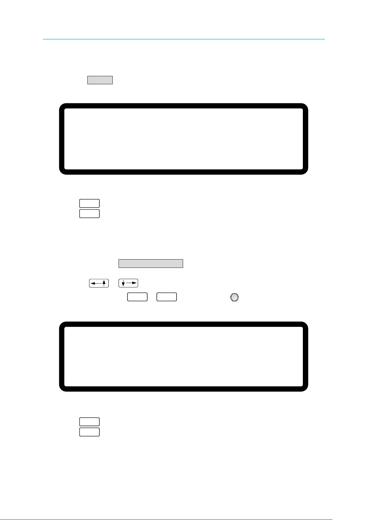
Programmable DC Power Supply (with Solar Array Simulation) 62000H Series
3-28
[ S E R I E S / P A R A L L E L
]
M A S T E R O R S L A V E = M A S T E R
M / S T E R M I N A T O R = D I S A B L E
P A R A L L E L O R S E R I E S = S E R I E S _
N U M . O F S L A V E = 1
M A S T E R & S L A V E C O N T R O L = N O
D I S C O N N E C T T H E C U R R E N T S H A R I N G C A B L E T O
P R E V E N T D A M A G E A T S E R I E S
0
9
[
S E R I E S /
P A R A L L E L ]
M A S T E R O R S L A V E = M A S T E R
M / S T E R M I N A T O R
= D I S A B L E
P A R A L L E L O R S E R I E S
= P A R A L L E L
N U M . O F S L A V E
= 4 _
M A S T E R & S L A V E C O N T R O L =
N O
ENTER
EXIT
ENTER
EXIT
Operating & Programming Manual
Connect the cables on the rear panel as shown in Figure 3-34 when set to SERIES and
as shown in Figure 3-35 when set to PARALLEL.
Selecting SERIES will display the window shown in Figure 3-42 to remind the user to
disconnect the CURRENT SHARING cable on the rear panel.
Figure 3-42
3. Press “ ” to confirm.
4. Press “ ” to return to the MAIN PAGE.
3.3.3.3.4 Setting NUM. OF SLAVE
When a DC Power Supply is set to MASTER, the number of SLAVEs must be set as well. If
there are 4 SLAVEs, set NUM. OF SLAVE = 4 as shown below in Figure 3-43.
1. Use the “
2. Use the numeric keys (
SLAVEs.
3. Press “ ” to confirm.
4. Press “ ” to return to the MAIN PAGE.
”, “ ” keys to move the cursor to the column to be set.
-
) or the “Rotary” ( ) knob to set the number of
Figure 3-43
Page 77

Manual Operation
3-29
Using the 62150H-600S as an example:
[ S E R I E S / P A R A L L E L ]
M A S T E R O R S L A V E
= M A S T E R
M / S T E R M I N A T O R = D I S A B L E
P A R A L L E L O R S E R I E S
= P A R A L L E L
N U M . O F S L A V E = 4
M A S T E R & S L A V E C O N T R O L = Y E S _
∑ V
= 6 0. 0 0 _
V I = 1 0.
0 0 A M S T O F F
0 .
0 0 0 0 V 0 .
0 0 0 0 A
0 . 0 W
1
ENTER
1. If there are 5 sets connected in parallel for 600V/100A, each unit
should be set for 600V/20A and the total output will be 600V/100A.
2. If there are 2 sets connected in series for 1200V/25A, each unit
should be set for 600V/25A and the total output will be 1200V/25A.
3. A maximum of 2 units may be connected in series; therefore, the
maximum number of NUM. OF SLAVE i s 1.
4. A maximum of 10 units may be connected in parallel; therefore, the
maximum number of NUM. OF SLAVE i s 9.
3.3.3.3.5 Activating MASTER & SLAVE CONTROL
When connecting units in PARALLEL OR SERIES, set NUM. OF SLAVE in the MASTER unit
as described below:
1. Use the “
Figure 3-44.
2. Use the numeric key ( ) or the “Rotary” (
”, “ ” keys to move the cursor to the column to be set as shown in
) knob to set YES.
Figure 3-44
3. Press “ to confirm and the menu will automatically switch to the series/parallel
MASTER page as shown in Figure 3-45.
4. The SLAVE page will automatically switch to Figure 3-46.
Figure 3-45
Page 78
Programmable DC Power Supply (with Solar Array Simulation) 62000H Series
3-30
O N L I N E
S L A V E 1
1. Communication errors will occur if the SLAVE settings are the same
S L A V E 1
M E A S
.
E R R
operation.
CAUTION
Operating & Programming Manual
Figure 3-46
5. The units are now ready to be used in the series/parallel mode.
(such as SLAVE 1 & SLAVE 1). The MAIN PAGE of the MASTER
unit will show the following message if this type of error occurs . First
exit the series/parallel operation and then change the SLAVE setting
to resume operation.
2. Once the series/parallel settings a re completed, the settings can be
saved. After all machines are powered off, turn on the SLAVEs first
and then the MASTER as it will automatically set the series/ parallel
3.3.3.4 Setting Series Parameters
Figure 3-47
The following parameter setting screens display once the software communication and
hardware settings for series operation are completed - (1) MAIN PAGE, (2) SYSTEM SETUP,
(3) OUTPUT SETUP and (4) PROTECTION.
3.3.3.4.1 Setting MAIN PAGE
MAIN PAGE is used to set voltage (V) and current (I). The difference between single unit
and series operation is that the voltage setting will increase acc ording to the number of units
connected in series. The voltage setting is indicated by ΣV for easy identification. When
set to MASTER, MST will appear in the window’s upper right corner as shown in Figure 3-48
below.
Page 79

Manual Operation
3-31
∑ V
= 6 0
.
0 0 _
V I = 1 0.
0 0
A M S T O F F
0
. 0 0 0 0
V
0 .
0 0 0 0 A
0 .
0 W
[S Y S T E M S E T U P
]
A P G V S E T
=
N O N E
A P G I S E T
=
N O N E
A P G V M E A S
= N O N E
A P G I M E A S
=
N O N E
B U Z Z E R
= O N
P O W E R O N S T A T E S
=
U S E R D E F I N I T I O N
_
∑ V
=
1 2 0 0
.
0 0 V I
=2 5
. 0 0 0
A O U T P U T = O F F
It will return to single unit mode once the POWER ON STATUS is set in
voltage and current to 0 and OUTPUT to OFF.
Figure 3-48
3.3.3.4.2 Setting SYSTEM SETUP for Series
The operation of POWER ON STATUS in [SYSTEM SETUP] during series operation is the
same as for a single unit except the output voltage will increase based on the number of units
connected in series. For example, if there are 2 sets of 62150H-600S in series, the
maximum output voltage that can be set is 1200V, and the maximum output current is 25A, as
shown in
Figure 3-49 below:
Figure 3-49
series mode. The POWER ON STATUS automatically sets the output
3.3.3.4.3 Setting OUTPUT SETUP for Series
The V LIMIT MAX in [OUTPUT SETUP] in the MASTER unit in a series connection will
increase based on the number of units connected in series. The set voltage is indicated by
ΣV LIMIT: MAX for easy identification as shown in Figure 3-50 below. The setting range of ΣV
SLEW RATE will also increase based on the number of units connected in series.
Page 80

Programmable DC Power Supply (with Solar Array Simulation) 62000H Series
3-32
[ P R O T E C T I O N
]
∑
O V P
=
6 0 0
. 0
_ V
O C P
=
1 8
.
9 0
A
∑
O P P
=
1 0 5 0 0
.
0
W
R E M O T E I N H I B I T
=
D I S A B L E P U L L =
H I G H
S A F E
T Y I N T
. L O C K
= D I S A B L E P U L L
=
H I G H
E X T O N
/
O F F
= D I S A B L E P U L L
=
H I G H
[
O U T P U T S E T U P
]
Σ
V L I M I T
:
M A X =
6 0 0
.
0
_
V M I N
=
0
.
0
V
I L I M I T :
M A X
=
2 5
.
0 0
A M I N
=
0 .
0
A
Σ
V S L E W R A T E
=
1 .
0 0 0
(
V
/
m S
)
I S L E W R A T E
=
I N F
. (
A
/
m S
)
V D C
_
R
=
6
.
0
V V D C
_ F
= 6
.
0 V
▼
Operating & Programming Manual
Figure 3-50
3.3.3.4.4 Se tting PROTECTION for Series
The OVP and OPP [PROTECTION] settings in the MASTER unit in a series connection will
increase based on the number of units connected in series. They are indicated by ΣOVP
and ΣOPP for easy identification as shown in Figure 3-51 below.
Figure 3-51
3.3.3.5 Setting Parallel Parameters
The following parameter setting screens display once the software communication and
hardware settings for parallel operation are completed - (1) MAIN PAGE, (2) SYSTEM
SETUP, (3) OUTPUT SETUP and (4) PROTECTION.
3.3.3.5.1 Setting MAIN PAGE
MAIN PAGE is used to set voltage (V) and current (I). The difference between single unit
and parallel operation is that the current setting will increase according to the number of units
connected in parallel. The current setting is indicated by ΣI for easy identification. When
set to MASTER, MST will appear in the window’s upper right corner as shown in Figure 3-52
below.
Page 81

Manual Operation
3-33
V
=
6 0.
0 0 _
V
∑ I
= 1 0. 0 0
A M S T O F F
0
. 0 0 0 0
V
0 .
0 0 0 0
A
0 .
0
W
[S Y S T E M S E T U P
]
A P G V S E T
=
N O N E
A P G I S E T
=
N O N E
A P G V M E A S
= N O N E
A P G I M E A S
=
N O N E
B U Z Z E R
= O N
P O W E R O N S T A T E S
=
U S E R D E F I N I T I O N
_
∑ V
=
6 0 0
.
0 0 V I
= 1 2 5
. 0 0
A O U T P U T = O F F
It will return to single unit mode once the POWER ON STATUS is set in
current to 0 and OUTPUT to OFF automatically.
Figure 3-52
3.3.3.5.2 Setting SYSTEM SETUP for Parallel
The operation of POWER ON STATUS in [SYSTEM SETUP] for parallel operation is the
same as for a single unit except the output current will increase based on the number of units
connected in parallel. For example, if there are 5 sets of 62150H-600S in parallel, the
maximum output voltage that can be set is 600V, and the maximum output current is 125A, as
shown in
Figure 3-53 below:
Figure 3-53
parallel mode. The POWER ON STATUS sets the output voltage and
3.3.3.5.3 Setting OUTPUT SETUP for Parallel
The I LIMIT MAX in [OUTPUT SETUP] in the MASTER unit in a parallel connection will
increase based on the number of units connected in parallel. The current setting is indicated
by ΣV LIMIT: MAX for easy identification as shown in Figure 3-54 below. The setting range of
ΣV SLEW RATE will also increase based on the number of units connected in parallel.
Page 82

Programmable DC Power Supply (with Solar Array Simulation) 62000H Series
3-34
[ P R O T E C T I O N
]
O V P
= 6 0 0
.
0
_
V
∑
O C P
=
1 8 .
9 0
A
∑
O P P
=
1 0 5 0 0
.
0
W
R E M O T E I N H I B I T
=
D I S A B L E P U L L
=
H I G H
S A F E
T Y I N T
.
L O C K
= D I S A B L E P U L L
=
H I G H
E X T O N
/ O F F
=
D I S A B L E P U L L
=
H I G H
[
O U T P U T S E T U P
]
V L I M I T
:
M A X
= 6 0 0
.
0
_
V M I N
=
0
.
0
V
Σ
I L I M I T
:
M A X
=
2 5
.
0 0 A M I N
=
0
.
0
A
V S L E W R A T E
=
1 .
0 0 0 (
V
/
m S
)
Σ
I S L E W R A T E
=
I N F
. (
A
/ m S
)
V D C
_
R
=
6
.
0
V V D C
_
F =
6
.
0
V
▼
∑ V = 1 2 0 0
. 0 0 _ V I = 2 5. 0 0
A M S T O F F
0
. 0 0 0 0 V 0 . 0 0 0 0 A
0 . 0 W
A P G – V S A P G – I S
Operating & Programming Manual
Figure 3-54
3.3.3.5.4 Se tting PROTECTION for Parallel
The OCP and OPP [PROTECTION] settings in the MASTER unit in a parallel connection will
increase based on the number of units connected in parallel. They are indicated by ΣOCP
and ΣOPP for easy identification, as shown in Figure 3-55 below.
Figure 3-55
3.3.3.6 Setting Procedure for APG in Series or Parallel
3.3.3.6.1 Series Setting
The MAIN PAGE menu of the MASTER unit will display the following screen when connecting
two 62150H-600S DC Power Supplies for series operation and setting the APG option to APG
VSET/APG ISET = Vref(0-5V):
Figure 3-56
Page 83

Manual Operation
3-35
APG INPUT 5V/5V
DC SOURCE OUTPUT
1200V/25A
APG INPUT 10V/10V
DC SOURCE OUTPUT
1200V/25A
V = 6 0 0 .
0 0 _ V
∑ I = 1 2 5. 0 0 A M S T O F F
0 . 0 0 0 0 V
0 . 0 0 0 0 A
0 . 0
W
A P G – V S A P G – I S
The external analog voltage 0-5V maps to the actual output voltage (0-1200V) and the actual
output current (0-25A) as shown in Figure 3-57(a). When the APG option is set to APG
VSET/APG ISET = Vref(0-10V) the external analog voltage 0-10V maps to the actual output
voltage (0-1200V) and the actual output current (0-25A) as shown in Figure 3-57(b). The
analog voltage signal wire needs to be routed through the APG interface connectors in series
in APG mode.
3.3.3.6.2 Parallel Setting
The MAIN PAGE menu of the MASTER unit will display the follow ing screen when connecting
five 62150H-600S DC Power Supplies for parallel operation and setting the APG option to
APG VSET/APG ISET = Vref(0-5V):
The external analog voltage 0-5V maps to the actual output voltage (0-600V) and the actual
output current (0-125A) as shown in Figure 3-59(a). When the APG option is set to APG
VSET/APG ISET = Vref(0-10V) the external analog voltage 0-10V maps to the actual output
voltage (0-600V) and the actual output current (0-125A) as shown in Figure 3-59(b). The
analog voltage signal wire needs to be routed through the APG interface connectors in series
in APG mode.
(a) (b)
Figure 3-57
Figure 3-58
Page 84

Programmable DC Power Supply (with Solar Array Simulation) 62000H Series
3-36
APG INPUT 5V/5V
DC SOURCE OUTPUT
600V/125A
APG INPUT 10V/10V
DC SOURCE OUTPUT
600V/125A
1. There are 3 selections for BRIGHTNESS: HIGH /NORMAL/
DIMMED. The default is HIGH.
[ D I S P L A Y S E T U P ]
B R I G H T N E S S = H I G H _
D I S P L A Y S E L E C T I O N = N O N E
R E A D I N G A V E R A G E T I M E S = 2
A V E R A G E M E T H O D = F I X E D
0
2
ENTER
EXIT
Operating & Programming Manual
(a) (b)
Figure 3-59
3.3.4 DISPLAY
The DISPLAY setting has 4 options: (1) BRIGHTNESS (2) DISPLAY SELECTION (3)
READING AVERAGE TIMES (4) AVERAGE METHOD.
3.3.4.1 BRIGHTNESS
This option sets the backlight panel brightness of the VFD on the front panel. There are 4
backlight brightness settings to select from (including tur n off the backlight) for use in various
situations.
1.
Use the “ ”, “ ” keys to move the cursor to the column to be set as shown in
Figure 3-60.
Figure 3-60
2. Use the numeric keys ( - ) or the “Rotary” ( ) knob to select the VFD
backlight brightness.
3. Press “ ” to conf irm.
4. Press “ ” to return to the MAIN PAGE.
Page 85

Manual Operation
3-37
2. Settings and brightness descriptions:
burn-in to prolong the product life of the VFD display.
0
3
0
1
2
4
ENTER
[ D I S P L A Y S E T U P ]
B R I G H T N E S S = H I G H
D I S P L A Y S E L E C T I O N = N O N E _
R E A D I N G A V E R A G E T I M E S = 2
A V E R A G E M E T H O D = F I X E D
a. Press “ ”, BRIGHTNESS = HIGH.
b. Press “ ”, BRIGHTNESS = NORMAL.
c. Press “ ”, BRIGHTNESS = DIMMED.
3. The lower the backlight brightness, the longer the display panel life.
Set the backlight brightness to DIMMED when the device is doing
3.3.4.2 DISPLAY SELECTION
Setting the DISPLAY SELECTION shows the internal settings on the last line of MAIN PAGE
for easy identification without entering the setting page. There are 4 options available for
displaying on the MAIN PAGE: (1) NONE, (2) V/I LIMIT, (3) V/I/P PROTECT, and (4) V/I
SLEWRATE.
1. In the Config setting page, press “ ” to display the screen then “ ” to enter into
DISPLAY SELECTION as shown in Figure 3-61.
Figure 3-61
2. Use the “
”, “ ” keys to move the cursor to the column to be set as shown in
Figure 3-61.
3. Use the numeric keys (
-
) or the “Rotary” ( ) knob to select the desired
setting. There are 4 selections on the MAIN PAGE: (1)NONE, (2)V/I LIMIT, (3)V/I/P
PROTECT and (4)V/I SLEWRATE. The system default is NONE.
When the selection is set to NONE, the MAIN PAGE does not show any message on the
last line.
When the selection is set to V/I LIMIT, the last line on MAIN PAGE will show the range
set by V LIMIT and I LIMIT in the OUTPUT SETUP as shown in Figure 3-62. See
sections 3.3.2.1 and 3.3.2.2 for a detailed description.
Page 86

Programmable DC Power Supply (with Solar Array Simulation) 62000H Series
3-38
V =
6 0
. 0 0 V I = 1 0. 0 0 _
A O F F
0 . 0 0 0 0 V 0 . 0 0 0 0
A
0
. 0
W
V _ L I M : 2 0 . 0 – 1 0 0 . 0 I_ L I M
: 2
.
0 0 –
1 8
. 0 0
V = 6 0. 0 0 V I = 1 0. 0 0 _ A O F F
0 . 0 0 0 0 V 0 . 0 0 0 0 A
0 . 0 W
O V P = 6 6 0 . 0 V O C P = 1 8 . 9 0 A O P P = 1 0 5 0 0 . 0 W
V = 6 0. 0 0 V I = 1 0. 0 0 _ A O F F
0 . 0 0 0 0 V 0 . 0 0 0 0 A
0 . 0 W
V _ S / R : 1 0 .0 0 0 ( V / m s ) I _ S / R : 0 . 0 0 1 ( A / m s )
Operating & Programming Manual
Figure 3-62
When the selection is set to V/I /P PROTECT, the last line of the MAIN PAGE will show
the OVP, OCP and OPP settings in the PROTECTION as shown in Figure 3-63. See
sections 3.3.5.1 - 3.3.5.3 for a detailed description.
Figure 3-63
When the selection is set to V/I SLEW, the last line on the MAIN PAGE will show the
settings of V SLEWRATE and I SLEWRATE in the OUTPUT SETUP as shown in Figure
3-64. See sections 3.3.2.3 and 3.3.2.4 for a detailed description
Figure 3-64
Page 87

Manual Operation
3-39
0
3
0
1
1. As an example, setting the READING AVERAGE TIME = 8 and
A1A2 A3A4
A5
A6
A7
A8
B
1B2 B3B4B5B
6 B
7
B8
All New vaules
buffer buffer
Next time
A1A2 A3
A4
A5
A6 A
7
A8
buffer
buffer
Next time
A1
A2 A3
A4
A5
A6A7A8
A9
A10
3. The panel reading is refreshed every 200mS.
[ D I S P L A Y S E T U P ]
B R I G H T N E S S = H I G H
D I S P L A Y S E L E C T I O N = N O N E
R E A D I N G A V E R A G E T I M E S = 2 _
A V E R A G E M E T H O D = F I X E D
3.3.4.3 READING AVERAGE TIMES
The READING AVERAGE TIMES sets the numb er of samples to be averaged and displayed
on the MAIN PAGE screen. The default is 2. When changing the READING AVERAGE
TIMES default, the average method can also be changed.
Figure 3-65
Follow the steps below to change the average times and method:
1. Use the numeric keys “
2. Use the numeric keys
”, “ ” to move the cursor to the column to be set.
-
or the “Rotary” ( ) knob to select the number
of samples to be averaged. READING AVERAGE TIME can be set to 1, 2, 4 and 8.
3. Move the cursor to AVERAGE METHOD and use the numeric keys (
the “Rotary” ( ) knob to select the desired average method. AVERAGE METHOD has
two options: FIXED and MOVING.
AVERAGE METHOD = FIXED, the next sampling clears all of the old
samples (A1 - A8) in the buffer and saves the new samples (B1 - B8),
then averages them as shown in
Figure 3-66
2. Setting the READING AVERAGE TIME = 8 and AVERAGE
METHOD:MOVING, the next sampling removes the oldest sample in
the buffer and saves the new sample, then averages them as shown in
Figure 3-67.
Figure 3-66.
-
) or
Figure 3-67
Page 88

Programmable DC Power Supply (with Solar Array Simulation) 62000H Series
3-40
CONF
[
P R O T E C T I O N
]
O V P
=
6 0 0
.
0
_
V
O C P
=
1 8
.
9 0
A
O P P
= 5 2 5 0
.
0
W
R E M O T E I N H I B I T
=
D I S A B L E P U L L =
H I G H
S A F E
T Y I N T
.
L O C K
=
D I S A B L E P U L L
=
H I G H
E X T O N /
O F F
= D I S A B L E P U L L
= H I G H
▼
the cursor to the column to be set.
[ P R O T E C T I O N ]
O V P
= 6 0 0 . 0 _ V
O C P
= 1 8 . 9 0 A
O P P
=
5 2 5 0 . 0 W
R E M O T E I N H I B I T
= D I S A B L E P U L L = H I G H
S A F E T Y I N T
. L O C K
= D I S A B L E P U L L =
H I G H
E X T O N
/ O F F = D I S A B L E P U L L = H I G H
▼
5
ENTER
Operating & Programming Manual
3.3.5 PROTECTION
Chroma 62000H Series DC Power Supplies with Solar Array Simulation have protection
functions divided into two classes. The first protection class includes over voltage, over
current, over power and FOLDBACK; the second protection class includes over temperature,
fan failure and over/under input voltage. The first class of protection trigger points is set by the
user as described below, while the second protection class is auto detected by the system
hardware protection circuits.
To ent er into the Protection mode:
1. Press “
” to go to the Config Setup page.
2. Press “ ” then “ ” to enter into the PROTECTION selection page as shown in
Figure 3-68.
Figure 3-68
When in the selection page, use the “
”, “ ” keys to move
3.3.5.1 OVP Protection
1. Use the “ ”, “ ” keys to move the cursor to the column to be set as shown in
Figure 3-69.
Figure 3-69
Page 89

Manual Operation
3-41
0
EXIT
Table 3-2 shows the voltage range of OVP.
Model
Min. OVP (V)
Max. OVP (V)
62xxxH-xxxxS
0
1.10 x Vo_MAX
V = 6 0. 0 0 V I = 1 0. 0 0 _ A O F F
0 . 0 0 0 0 V 0 . 0 0 0 0 A
O V P 0 . 0 W
[ P R O T E C T I O N ]
O V P
= 6 0 0 . 0
V
O C P
=
8 . 9 2 _ A
O P P
= 5 2 5 0 .
0 W
R E M O T E I N H I B I T
= D I S A B L E P U L L = H I G H
S A F E T Y I N T . L O C K
= D I S A B L E P U L L = H I G H
E X T O N / O F F
= D I S A B L E P U L L = H I G H
▼
0
9
EXIT
9
ENTER
ENTER
2. Use the numeric keys (
- ) or the “Rotary” ( ) knob to set the value.
3. Press “ ” to confirm.
4. Press “
” to return to the MAIN PAGE.
This function sets the protection point for Over Voltage. If the output voltage exceeds the
range, it will turn off the output to protect the unit under test.
Table 3-2 OVP Range
If an OVP occurs th e MAI N PAG E will display a prot ect ion message as shown in Figure 3-70.
Figure 3-70
3.3.5.2 OCP Protection
1. Use the “ ”, “ ” keys to move the cursor to the column to be set as shown in
Figure 3-71.
2. Use the numeric keys (
3. Press “ ” to confirm.
4. Press “
Figure 3-71
-
” to return to the MAIN PAGE.
) or the “Rotary” ( ) knob to set the value.
Page 90
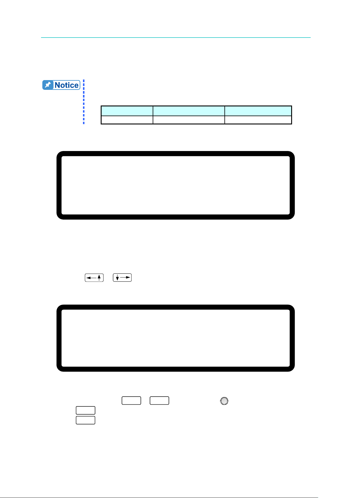
Programmable DC Power Supply (with Solar Array Simulation) 62000H Series
3-42
Table 3-3 shows the current range of OCP.
Model
Min. OCP (A)
Max. OCP (A)
62xxxH-xxxxS
0
1.05 x Io_MAX
V = 6 0. 0 0 V I = 1 0. 0 0 _ A O F F
0 . 0 0 0 0 V 0 . 0 0 0 0 A
O C P 0 . 0 W
[ P R O T E C T I O N ]
O V P
= 6 0 0 . 0 _
V
O C P
= 1 8 . 9 0 A
O P P
=
5 2 5 0 . 0 W
R E M O T E I N H I B I T
= D I S A B L E P U L L = H I G H
S A F E T Y I N T . L O C K
=
D I S A B L E P U L L = H I G H
E X T O N / O F F = D I S A B L E P U L L = H I G H
▼
0
9
EXIT
ENTER
Operating & Programming Manual
This function sets the protection point for Over Current. If the output current exceeds the
range, it will turn off the output to protect the unit under test.
Table 3-3
If an OCP occurs the MAIN PAGE will display a protection message as shown in Figure 3-72.
Figure 3-72
3.3.5.3 OPP Protection
1. Use the “ ”, “ ” keys to move the cursor to the column to be set as shown in
Figure 3-73.
2. Use the numeric keys (
3. Press “ ” to confirm.
4. Press “
This function sets the protection point for Over Power. If the output power exceeds the range,
it will turn off the output to protect the unit under test.
Figure 3-73
-
” to return to the MAIN PAGE.
) or the “Rotary” ( ) knob to set the value.
Page 91

Manual Operation
3-43
1. Table 3-4 shows the power range of OPP.
Model
Min. OPP (W)
Max. OPP (W)
62xxxH-xxxxS
0
1.05 x Po_MAX
power of the output current and remote sense voltage.
V
= 6 0
.
0 0 V I = 1 0. 0 0 _
A O F F
0 . 0 0 0 0 V 0 . 0 0 0 0 A
O P P 0 . 0 W
[ P R O T E C T I O N
]
O V P
= 6 0 0 .
0 V
O C P
= 1 8 . 9 0 A
O P P
= 5 2 5 0
. 0 W
R E M O T E I N H I B I T
= D I S A B L E _
P U L L = H I G H
S A F E
T Y I N T . L O C K
= D I S A B L E P U L L = H I G H
E X T O N /
O F F = D I S A B L E P U L L = H I G H
▼
0
1
Table 3-4
2. The OPP protection point is based on the comparison of the calculated
If an OPP occurs the MAIN PAGE will displaty a protection message as shown in Figure 3-74.
Figure 3-74
3.3.5.4 REMOTE INHIBIT
This function controls the power supply’s ON/OFF function directly through PIN 9 (_INHIBIT)
of the ANALOG INTERFACE in the APG & SYSTEM STATUS menus.
1. Use the “
Figure 3-75.
2. Use the numeric keys
INHIBIT mode. There are two options: DISABLE and ENABLE.
1. Selecting DISABLE: Disables the remote function.
” “ ” keys to move the cursor to the column to be set as shown in
Figure 3-75
-
or the “Rotary” ( ) knob to set the REMOTE
Page 92

Programmable DC Power Supply (with Solar Array Simulation) 62000H Series
3-44
ON/OFF
ON/OFF
ON/OFF
EXIT
V = 6 0. 0 0 V I = 1 0. 0 0 _ A O F F
0 . 0 0 0 0 V 0 . 0 0 0 0 A
I H B 0 . 0 W
ENTER
Operating & Programming Manual
2. Selecting ENABLE: Sets the REMOTE INHIBIT to ENABLE. The DC Power
Supply’s ON/OFF is still controlled by the “
When P in 9 (_INHIBIT) of the ANALOG INTERFACE is
triggered by a Low Level (same as pressing the “
key on the front panel) it sets OUTPUT = OFF. The DC
Power Supply will shut down and send out a protection
signal (in this case the “
(_INHIBIT) of the ANALOG INTERFACE cannot be used to
release the protection.
3. Press “ ” to confirm.
4. Press “
3. When protection occurs due to a REMOTE INHIBIT signal the MAIN PAGE will display
the protection message as shown in Figure 3-76.
” to return to the MAIN PAGE.
” will be OFF.) Pin 9
” key.
”
Figure 3-76
4. Pin 9 is a TTL Level input pin. The initial state can be set to PULL=HIGH or PULL=LOW.
5. When the DC Power Supply is set to OUTPUT = ON, the REMOTE INHIBIT signal will
control the output as shown in Figure 3-77.
Page 93

Manual Operation
3-45
_INHIBIT
SIGNAL
INHIBIT
=DISABLE
INHIBIT
=ENABLE
Output
Output
0
1
OUTPUT
ON/OFF
[ P R O T E C T I O N ]
O V P
= 6 0 0 . 0 V
O C P
= 1 8 . 9 0 A
O P P
= 5 2 5 0 . 0 W
R E M O T E I N H I B I T
= D I S A B L E P U L L = H I G H
S A F E
T Y I N T . L O C K
= D I S A B L E _ P U L L = H I G H
E X T O N / O F F = D I S A B L E P U L L = H I G H
▼
Figure 3-77
3.3.5.5 SAFETY INT.LOCK
This function controls the power supply’s ON/OFF function directly through Pin 21
(INTERLOCK) of the ANALOG INTERFACE.
1. Use the “
Figure 3-78.
2. Use the numeric keys
INT.LOCK mode. There are two options, DISABLE and ENABLE.
1. Selecting DISABLE: Disables this function.
2. Selecting ENABLE: Sets SAFETY INT.LOCK to ENABLE. The DC Power
” “ ” keys to move the cursor to the column to be set as shown in
Figure 3-78
-
or the “Rotary” ( ) knob to set the SAFETY
Supply’s ON/OFF is still controlled by “
21 of the ANALOG INTERFACE is at a low lev el, it indicates
the power supply is outputting normally and when it is at a
high level, it stops the power supply output temporary (the
“
” is still on) and issues a protection signal. Once Pin
”. When PIN
Page 94

Programmable DC Power Supply (with Solar Array Simulation) 62000H Series
3-46
EXIT
V = 6 0. 0 0 V I = 1 0. 0 0 _ A O F F
0 . 0 0 0 0 V 0 . 0 0 0 0 A
S A F E T Y I N T E R L O C K 0 . 0 W
INTERLOCK
SIGNAL
INTERLOCK
=DISABLE
INTERLOCK
=ENABLE
Output
Output
ENTER
Operating & Programming Manual
21 of the ANALOG INTERFACE is returned to a low level,
the DC Power Supply will continue to output normally.
3. Press “ ” to confirm.
4. Press “
3. If a protection occurs due to a SAFETY INT.LOCK signal the MAIN PAGE will display the
protection message as shown in Figure 3-79.
4. Pin 21 is a TTL Level input pin. The initial state can be set to PULL=HIGH or
PULL=LOW.
5. When the DC Power Supply is set to OUTPUT = ON, the SAFETY INT.LOCK sign al will
control the output as shown in Figure 3-84.
” to return to the MAIN PAGE.
Figure 3-79
Figure 3-80
Page 95

Manual Operation
3-47
[ P R O T E C T I O N
]
O V P
=
6 0 0 . 0 V
O C P
= 1 8
.
9 0 A
O P P
= 5 2 5 0
. 0
W
R E M O T E I N H I B I T
=
D I S A B L E P U L L =
H I G H
S A F E T Y I N T . L O C K
= D I S A B L E P U L L
=
H I G H
E X T O N
/
O F F = D I S A B L E _ P U L L
= H I G H
▼
0
9
ON/OFF
ON/OFF
EXIT
V
= 6 0. 0 0
V I = 1 0.
0 0 _ A O F F
E X T
0 . 0 0 0 0 V 0 . 0 0 0 0 A
0 . 0 W
ENTER
3.3.5.6 EXTERNAL ON/OFF
This function controls the DC Power Supply’s ON/OFF through Pin 22 (_EXT_ON) of the
ANALOG INTERFACE.
1. Use the “
”, “ ” keys to move the cursor to the column to be set as shown in
Figure 3-81.
Figure 3-81
2. Use the numeric keys (
-
) or the “Rotary ” ( ) knob to set the EXTERNAL
ON/OFF mode. This function has two options: DISABLE and ENABLE.
1. Selecting DISABLE: Disables this function.
2. Selecting ENABLE: Sets EXTERNAL ON/O FF to ENABLE and disables the
“
” key. Pin 22 (_EXT_ON) replaces the “
to control the Power Supply’s ON/OFF function. When
the Pin 22 (_EXT_ON) voltage level on the ANALOG
INTERFACE goes HIGH, the Power Supply output is
turned OFF. When the Pin 22 (_EXT_ON) voltage level
goes LOW, the DC Power Supply is turned ON.
3. Press “ ” to confirm.
4. Press “
” to return to the MAIN PAGE.
3. When EXT. ON/OFF is enabled, th e MAIN PAGE will display the EXT messa ge as
shown in Figure 3-82.
” key
Figure 3-82
Page 96

Programmable DC Power Supply (with Solar Array Simulation) 62000H Series
3-48
_EXT ON
SIGNAL
EXT ON
=DISABLE
EXT ON
=ENABLE
Output
Output
[ P R O T E C T I O N ]
F O L D B A C K
= D I S A B L E
▲
0
1
Operating & Programming Manual
4. Pin 22 is a TTL Level input pin. The initial state can be set to PULL=HIGH or
PULL=LOW.
5. When the DC Power Supply is set to OUTPUT = ON, the EXTERNAL ON/OFF signal will
control the output as shown in Figure 3-83.
Figure 3-83
3.3.5.7 FOLDBACK
This function turns off the output when the output mode is changed (CV TO CC or CC TO CV)
to protect the unit under test.
1. Use the “
Figure 3-84.
”, “ ” keys to move the cursor to the column to be set as shown in
Figure 3-84
2. Use the numeric keys (
mode. There are three options available for selection: DISABLE, CV TO CC and CC TO
-
) or the “Rota ry ” ( ) knob to set the FOLDBACK
CV.
Page 97

Manual Operation
3-49
[ P R O T E C T I O N ]
F O L D B A C K = C V T O C C_
D E L A Y T I M E = 0 . 0 1 S
V = 6 0. 0 0 V I = 1 0. 0 0 _ A O F F
0 . 0 0 0 0 V 0 . 0 0 0 0 A
C V T O C C F O L D B A C K 0 . 0 W
1. DISABLE: Ignore the output off function.
2. CV TO CC: Active in CV MODE only. When the mode is changed to CC MODE,
the system will turn off the output to protect the UUT.
3. CC TO CV: Active in CC MODE only. When the mode is change d to CV MODE,
the system will turn off the output to protect the UUT.
When the FOLDBACK option is set to CV TO CC or CC TO CV, a selection for DELAY
TIME will display to set the time delay for protection to occur after a mode change, as
shown in Figure 3-85.
Figure 3-85
If FOLDBACK protection occurs the MAIN PAGE will display a protection message as
shown in Figure 3-86.
Figure 3-86
If DELAY TIME is set to t seconds, FOLDBACK will not be activated until t seconds after
a mode change is detected. If the mode change switches back in less than t seconds
the DC source operation mode will return to its original state and FOLDBACK protection
will not , as shown in Figure 3-87.
Page 98

Programmable DC Power Supply (with Solar Array Simulation) 62000H Series
3-50
DELAY TIME
C
V MODE
CC MODE
Time
FOLDBACK
PROTECTION
DC SOURCE OPERATION MODE
EXIT
V = 6 0. 0 0 V I = 1 0. 0 0 _ A O F F
0 . 0 0 0 0 V 0 . 0 0 0 0 A
O T P 0 . 0 W
1. The OTP limit setting cannot be changed by the operator.
again until the internal temperature drops to a set value.
ENTER
Operating & Programming Manual
Figure 3-87
Assuming the FOLDBACK is set to CV TO CC, the solid line in Figure 3-87 indicates
when Foldback protection occurs while the dotted line indicates when it will not occur.
3. Press “ ” to confirm.
4. Press “
” to return to the MAIN PAGE.
3.3.5.8 OTP
The OTP protection will activate when the internal temperature reaches the high limit. The
output will be turned off.
If an OTP occurs the MAIN PAGE menu will display a protection message as shown in Figure
3-88.
Figure 3-88
2. The output will turn OFF when an OTP occurs and will not turn ON
Page 99

Manual Operation
3-51
V = 6 0. 0 0 V I = 1 0. 0 0 _ A O F F
0 . 0 0 0 0 V 0 . 0 0 0 0 A
A C _ F A U L T 0 . 0 W
S H U T – D N
1. The table below lists the typical values for an AC FAULT in the
Line to Line Rated Voltage
Lower than
(Vac)
Higher than
(Vac)
200/220Vac
180
242
380/400Vac
342
440
440/480Vac
396
528
200/240Vac
180
264
FAULT may occur. See section 2.3.2 for the wire diameter spec.
3.3.5.9 AC FAULT
The AC FAULT protection will activate w hen the i nternal input v oltage is n ot w ithin the model’s
range, or when the input voltage is too low. The output will turn OFF.
If an AC FAULT occurs, the MAIN PAGE will display a protection message as shown in
Figure 3-89.
Figure 3-89
62000H Series:
Table 3-5 AC FAULT Range
2. Once the AC FAULT is activated, the output is turned OFF. Power
OFF the device and then power it ON again after the correct input
voltage and connection are confirmed. If the input voltage or
connection is incorrect, AC FAULT protection will occur
continuously.
3. The diameter of the input wire must be large enough or the line loss
generated may cause the input voltage to be out of SPEC and an AC
3.3.5.10 SENSE FAULT Protection
The remote sense input is located on the rear panel near the output terminal (see section
2.4.1 for the correct connection). It adjusts the power supply’s output so the UUT’s voltag e is
consistent with the voltage set on the front panel so the UUT is not affected by the voltage
drop across the load wires.
(1) If the connection is wrong, for instance the VOLTAGE SENSING polarity is reversed (the
UUT’s “–” terminal is connected to the “+” of the output terminal and the UUT’s “+”
terminal is connected to the “–” of the output terminal), or
Page 100

Programmable DC Power Supply (with Solar Array Simulation) 62000H Series
3-52
V
= 6 0
.
0 0 V I
=
1 0
.
0 0
_
A O F F
0
.
0 0 0 0 V
0
. 0 0 0 0
A
S E N S E
_
F A U L T 0
.
0 W
S H U T
–
D N
V = 6 0
. 0 0 V I =
1 0. 0 0 _
A O F F
0 . 0 0 0 0 V 0
. 0 0 0 0 A
F A N
_ L O C K 0 . 0 W
S H U T – D N
Operating & Programming Manual
(2) The voltage drop across the load wire exceeds the full scale output voltage by 4%,
protection will occur when the load wire voltage drop > 600 x 0.04=24V (using the
62150H-600S as an example).
SENSE FAULT pr otection will turn OFF the output if either of these two situations occurs.
Connect the REMOTE SENSING wires correctly or increase the load wire size and reboot to
remove the fault.
If a SENSE FAULT occurs, the MAIN PAGE menu will display a protection message as
shown in Figure 3-90 shows.
Figure 3-90
3.3.5.11 FANLOCK Protecti on
Fans are installed inside the DC Power Supply to ventilate the heat generated by components.
If one of the fans fails, FANLOCK protection will occur and the output will turn OFF.
If a FANLOCK occurs the MAIN PAGE menu will display a protection message as shown in
Figure 3-91.
Figure 3-91
 Loading...