

Christie TVC-500 User Manual

TVC-500
USER MANUAL
020-100539-01


TVC-500
USER MANUAL
020-100539-01

NOTICES
COPYRIGHT AND TRADEMARKS
© 2010 Christie Digital Systems USA, Inc. All rights reserved.
All brand names and product names are trademarks, registered trademarks or trade names of their respective holders.
REGULATORY
The product has been tested and found to comply with the limits for a Class A digital device, pursuant to Part 15 of the FCC Rules. These limits are
designed to provide reasonable protection against harmful interference when the product is operated in a commercial environment. The product
generates, uses, and can radiate radio frequency energy and, if not installed and used in accordance with the instruction manual, may cause harmful
interference to radio communications. Operation of the product in a residential area is likely to cause harmful interference in which case the user will
be required to correct the interference at the user’s own expense.
This Class A digital apparatus complies with Canadian ICES-003.
Cet appareil numérique de la classe A est conforme à la norme NMB-003 du Canada.
이 기기는 업무용 (A 급 ) 으로 전자파적합등록을 한 기기이오니 판매자 또는 사용자는 이점을 주의하시기 바라며 , 가정 외의 지역에서 사용하는 것을 목적
으로 합니다 .
GENERAL
Every effort has been made to ensure accuracy, however in some cases changes in the products or availability could occur which may not be reflected
in this document. Christie reserves the right to make changes to specifications at any time without notice. Performance specifications are typical, but
may vary depending on conditions beyond Christie's control such as maintenance of the product in proper working conditions. Performance
specifications are based on information available at the time of printing. Christie makes no warranty of any kind with regard to this material, including,
but not limited to, implied warranties of fitness for a particular purpose. Christie will not be liable for errors contained herein or for incidental or
consequential damages in connection with the performance or use of this material.
The product is designed and manufactured with high-quality materials and components that can be recycled and reused. This symbol means that
electrical and electronic equipment, at their end-of-life, should be disposed of separately from regular waste. Please dispose of the product
appropriately and according to local regulations. In the European Union, there are separate collection systems for used electrical and electronic
products. Please help us to conserve the environment we live in!
Canadian manufacturing facility is ISO 9001 and 14001 certified.
WARRANTY
For complete information about Christie’s limited warranty, please contact your Christie dealer. In addition to the other limitations that may be
specified in Christie’s limited warranty, the warranty does not cover:
(a) Damage occurring during shipment, in either direction.
(b) Projector lamps (See Christie’s separate lamp program policy).
(c) Damage caused by use of a projector lamp beyond the recommended lamp life, or use of a lamp supplied by a supplier other than
Christie.
(d) Problems caused by combination of the product with non-Christie equipment, such as distribution systems, cameras, video tape
recorders, etc., or use of the product with any non-Christie interface device.
(e) Damage caused by misuse, improper power source, accident, fire, flood, lightening, earthquake or other natural disaster.
(f) Damage caused by improper installation/alignment, or by product modification, if by other than a Christie authorized repair service
provider.
(g) For LCD projectors, the warranty period specified applies only where the LCD projector is in “normal use.” “Normal use” means the LCD
projector is not used more than 8 hours a day, 5 days a week. For any LCD projector where “normal use” is exceeded, warranty coverage
under this warranty terminates after 6000 hours of operation.
(h) Failure due to normal wear and tear.
PREVENTATIVE MAINTENANCE
Preventative maintenance is an important part of the continued and proper operation of your product. Please see the Maintenance section for specific
maintenance items as they relate to your product. Failure to perform maintenance as required, and in accordance with the maintenance schedule
specified by Christie, will void the warranty.

Table of Contents
1: Introduction
1.1 Using this Manual........................................................................................................................ 1-1
1.2 Safety Warnings and Guidelines .................................................................................................1-1
1.2.1 Power Cords and Attachments............................................................................................. 1-1
1.2.2 Symbols and Labels for the TVC-500 Controller................................................................ 1-1
Warning Labels .....................................................................................................................1-1
1.2.3 Typographical Notations......................................................................................................1-2
1.3 Purchase Record and Service Contacts .......................................................................................1-3
1.4 TVC-500 Controller Overview.................................................................................................... 1-3
1.4.1 How the Controller Works................................................................................................... 1-3
1.4.2 List of Components.............................................................................................................. 1-3
1.4.3 Preventing Electrostatic Discharge...................................................................................... 1-4
1.4.4 Installation Guidelines .........................................................................................................1-4
Elevated Ambient Temperature ............................................................................................1-4
Reduced Air Flow ................................................................................................................. 1-4
Mechanical Loading .............................................................................................................1-4
Circuit Overloading ..............................................................................................................1-4
Reliable Grounding ...............................................................................................................1-4
1.5 Related Documents......................................................................................................................1-4
2: Hardware
2.1 About the TVC-500 Controller....................................................................................................2-1
2.1.1 Key Features and Capabilities .............................................................................................2-1
2.2 Unpacking the TVC-500 .............................................................................................................2-2
2.2.1 TVC-500 Main Chassis .......................................................................................................2-2
Main Box ..............................................................................................................................2-2
2.3 Component Identification ............................................................................................................2-3
2.3.1 Front Panel Components...................................................................................................... 2-3
2.3.2 Rear Panel Components.......................................................................................................2-4
2.4 RAID 1 ........................................................................................................................................2-5
2.4.1 Configurations .....................................................................................................................2-5
Recognizing Hard Drive Failures .........................................................................................2-5
Effects of a Hard Drive Failure ............................................................................................2-6
2.4.2 Disk Replacement - Automatic Rebuild ..............................................................................2-6
Degraded RAID 1 Volume ...................................................................................................2-6
3: Connecting the Controller
3.1 Input Channel and Display Numbering for TVC-500 .................................................................3-1
NOTE: Card positions 1 to 7, with the exception of 6, are PCIe slots. Position 6 is PCI. ...............3-1
Channel Reference ................................................................................................................3-1
3.2 Connecting Devices to the TVC-500...........................................................................................3-3
3.2.1 About Source Connections ..................................................................................................3-3
V8C Module .........................................................................................................................3-3
D2R2-E Module ...................................................................................................................3-3
3.3 Connecting Display Devices/Screens for TVC-500.................................................................... 3-4
TVC-500 Operation Manual i
020-100539-01 Rev. 1 (08-2010)

Table of Contents
DVI-D Cables .......................................................................................................................3-5
No DVI signal .......................................................................................................................3-5
3.4 Connecting Peripheral Devices....................................................................................................3-5
3.5 Connecting Power........................................................................................................................3-6
3.5.1 Power ON Controller ...........................................................................................................3-6
3.5.2 Power OFF Controller..........................................................................................................3-6
3.6 System Monitoring ......................................................................................................................3-7
3.6.1 Monitoring Hard Disk Drives ..............................................................................................3-7
3.6.2 Recognizing Hard Drive Failures ........................................................................................3-7
4: Service Guidelines
4.1 Christie Technical Support ..........................................................................................................4-1
4.2 Safety Precautions & Warnings...................................................................................................4-2
4.2.1 General Precautions .............................................................................................................4-2
4.2.2 AC / Power Precautions .......................................................................................................4-2
4.3 General Service Guidelines..........................................................................................................4-2
4.3.1 Ordering Parts ......................................................................................................................4-2
4.3.2 Replacing Modules ..............................................................................................................4-2
4.3.3 Repair Cautions....................................................................................................................4-3
4.3.4 Maintenance Cleaning..........................................................................................................4-3
Cautions ................................................................................................................................4-3
Cleaning the workstation case ..............................................................................................4-3
Cleaning the Keyboard .........................................................................................................4-3
Cleaning the Mouse ..............................................................................................................4-4
5: Troubleshooting
5.1 Overview......................................................................................................................................5-1
5.1.1 Troubleshooting Guidelines.................................................................................................5-1
5.1.2 Help With Troubleshooting .................................................................................................5-1
5.2 LED Color Definitions.................................................................................................................5-2
5.3 Diagnostic LED and Audible (beep) codes .................................................................................5-2
5.4 POST Error Messages..................................................................................................................5-6
6: Remove/Replace Chassis Components
6.1 Replacing Hot-Plug Components ................................................................................................6-1
6.2 Powering Down the Controller ....................................................................................................6-1
6.3 Main Chassis Side Access Panel .................................................................................................6-1
6.3.1 Removal ...............................................................................................................................6-1
6.3.2 Replacement.........................................................................................................................6-2
6.4 Airflow Guide ..............................................................................................................................6-2
6.4.1 Removal ...............................................................................................................................6-2
6.4.2 Replacement.........................................................................................................................6-3
6.5 Expansion Card Support ..............................................................................................................6-4
6.5.1 Removal ...............................................................................................................................6-4
6.5.2 Replacement.........................................................................................................................6-5
ii TVC-500 Operation Manual
020-100539-01 Rev. 1 (08-2010)

Table of Contents
6.6 Power Supply............................................................................................................................... 6-6
6.6.1 Removal ...............................................................................................................................6-6
6.6.2 Replacement.........................................................................................................................6-6
6.7 Optical Disk Drive.......................................................................................................................6-7
6.7.1 Removal ...............................................................................................................................6-7
6.7.2 Replacement.........................................................................................................................6-7
6.8 Hard Drive (SATA) .....................................................................................................................6-8
6.8.1 Removal ...............................................................................................................................6-8
6.8.2 Replacement.........................................................................................................................6-9
6.9 Expansion Card Guide/Front Fan Holder.................................................................................... 6-10
6.9.1 Removal ...............................................................................................................................6-10
6.9.2 Replacement.........................................................................................................................6-11
6.10 Memory Fans............................................................................................................................. 6-11
6.10.1 Removal ............................................................................................................................6-11
6.10.2 Replacement......................................................................................................................6-12
6.11 Memory .....................................................................................................................................6-12
6.11.1 Removal ............................................................................................................................6-13
6.11.2 Replacement......................................................................................................................6-13
6.12 Expansion Cards ........................................................................................................................6-14
6.12.1 Removal ............................................................................................................................6-14
6.12.2 Replacement......................................................................................................................6-15
6.13 CPU Heatsink ............................................................................................................................6-16
6.13.1 Removal ............................................................................................................................6-16
6.13.2 Replacement......................................................................................................................6-16
6.14 CPU ...........................................................................................................................................6-17
6.14.1 Removal ............................................................................................................................6-17
6.14.2 Replacement......................................................................................................................6-18
6.15 System Board............................................................................................................................. 6-18
6.15.1 Removal ............................................................................................................................6-18
6.15.2 Replacement......................................................................................................................6-19
6.16 Re-entering Controller Serial Number and Product ID .............................................................6-19
6.17 Battery .......................................................................................................................................6-20
6.17.1 Removal ............................................................................................................................6-20
6.17.2 Replacement......................................................................................................................6-21
7: Specifications
7.1 Hardware .....................................................................................................................................7-1
7.1.1 Main Chassis........................................................................................................................7-1
7.1.2 Main Memory ......................................................................................................................7-1
7.1.3 I/O Interfaces .......................................................................................................................7-1
7.1.4 Integrated SATA Storage Controller ...................................................................................7-2
7.1.5 Storage .................................................................................................................................7-2
7.1.6 Embedded PCI Express Gigabit NIC Server Adapter .........................................................7-2
7.2 Power Requirements....................................................................................................................7-3
7.3 Peripheral Devices....................................................................................................................... 7-3
7.4 Display/Video Architecture......................................................................................................... 7-3
TVC-500 Operation Manual iii
020-100539-01 Rev. 1 (08-2010)

Table of Contents
7.4.1 Graphics Output (D4C)........................................................................................................7-3
7.5 Input (Source Signal) Compatibility............................................................................................7-4
7.5.1 Video Input (V8C) ...............................................................................................................7-4
16-Port Multiple Video Input Module (V8C) .......................................................................7-4
Composite Input ....................................................................................................................7-4
7.5.2 DVI Input (D2R2-E) ............................................................................................................7-4
7.6 Regulatory....................................................................................................................................7-5
7.6.1 Safety ...................................................................................................................................7-5
7.6.2 Electro-Magnetic Compatibility .........................................................................................7-6
7.7 Reliability and Serviceability.......................................................................................................7-6
7.8 Quality .........................................................................................................................................7-6
7.9 Environment.................................................................................................................................7-6
iv TVC-500 Operation Manual
020-100539-01 Rev. 1 (08-2010)

1 Introduction
1.1 Using this Manual
This manual provides technical information on using the TVC-500 Controller and assisting Christie accredited
service technicians in its service and repair.
To prevent physical injury or equipment damage, it is important that you read Section 4
Service Guidelines in its entirety before performing any service procedure covered in this manual.
Disclaimer: Every effort has been made to ensure the information in this document is accurate and reliable.
However, due to constant research, the information in this document is subject to change without
notice. Christie Digital Systems assumes no responsibility for omissions or inaccuracies.
Updates to this document are published regularly, as required. Please contact Christie Digital
Systems for availability.
NOTE: Images in this manual are presented to illustrate the key steps for each service procedure.
1.2 Safety Warnings and Guidelines
1.2.1 Power Cords and Attachments
1) The North American rated line cord is provided with each unit. Ensure that you are
using a line cord, socket and power plug that meets the appropriate local rating standards.
an AC power cord recommended by Christie. Do not attempt operation if the AC supply and cord are
not within the specified voltage and power range.
Use only the attachments and/or accessories recommended by Christie. Use of others may result in the
risk of fire, shock or personal injury.
2) Use only
1.2.2 Symbols and Labels for the TVC-500 Controller
Warning Labels
Observe and follow all warnings and instructions marked on the chassis, the components in the controller and
in this document. The following symbols indicate potential hazards.
TVC-500 Operation Manual 1-1
020-100539-01 Rev. 1 (08-2010)

Section 1: Introduction
Table 1.1 Warning Labels
This symbol indicates the presence of hazardous energy circuits or
electrical shock hazards.
To reduce the risk of injury from electrical shock hazards, do not open this enclosure. Refer all
maintenance, upgrades and servicing to qualified personnel.
This symbol indicates that the area contains no user or field serviceable
parts and electrical shock hazards may be present.
To reduce the risk of injury from electrical
shock hazards, do not open this enclosure.
This symbol on an RJ-45 receptacle indicates a network interface
connection.
To reduce the risk of electric shock, fire, or
damage to the equipment, do not plug telephone or telecommunications connectors into this receptacle.
This symbol indicates the presence of a hot surface or hot component.
Contact with the hot surface may cause personal injury.
ponent, allow the surface to cool before touching.
Danger symbols indicate a hazardous situation which, if not avoided, will result in
death or serious injury.
Warning symbols indicate a hazardous situation which, if not avoided, could result in
death or serious injury.
Caution symbols indicate a hazardous situation which, if not avoided, could result in
minor or moderate injury.
NOTICE: Information provided with this heading alerts users to key points of interest not related to personal
injury.
1.2.3 Typographical Notations
• References to specific areas of the document appear italicized and underlined. When viewed online the text
appears in blue indicating a direct link to that section. For example, Section 2 Hardware.
• References to other documents appear italicized and bold, such as Service Manual.
• References to software menus and available options appear bold, such as Main menu.
• User input or messages that appear on screen, in status display units or other control modules appear in
Courier font. For example. “No Signal Present”, Login: christiedigital.
To reduce the risk of injury from a hot com-
• Error codes, LED status appear in bold, e.g.
• Operational states of modules appear capitalized, such as power ON/OFF.
1-2 TVC-500 Operation Manual
LP, A1, etc.
020-100539-01 Rev. 1 (08-2010)

1.3 Purchase Record and Service Contacts
Whether the controller is under warranty or the warranty has expired, Christie’s highly trained and extensive
factory and dealer service network is always available to quickly diagnose and correct malfunctions. Should a
problem be encountered with any part of the controller, contact your dealer. In most cases, servicing is
performed on site. If you have purchased the controller, fill out the information below and keep with your
records for future reference.
Dealer:
Dealer or Christie Sales/Service Contact Phone Number:
Controller Serial Number:
Purchase Date:
Installation Date:
Section 1: Introduction
You can also register your product on-line by visiting support.christiedigital.com
with all the latest product information, such as updates, technical bulletins, downloads, and Christie
newsletters.
For complete details on the warranty of your Christie product, please contact your Christie dealer.
1.4 TVC-500 Controller Overview
1.4.1 How the Controller Works
The controller accepts up to 16 simultaneous composite video inputs and up to 4 RGB or DVI inputs through
V8C and D2R2-E modules, respectively, and provides up to 12 DisplayPort or DVI outputs through D4C
modules to drive a video wall. It uses a redundant array of independent disks (RAID) in a mirrored configuration of 2 SATA drives.
MasterSuite 5.1 software is installed in the controller and provides the ability to manage video inputs and
output assignments.
1.4.2 List of Components
• TVC-500 Chassis
•Keyboard
• 2-button optical mouse with scroll wheel
•Windows 7 OS
• MasterSuite 5.1
. This will keep you in touch
TVC-500 Operation Manual 1-3
020-100539-01 Rev. 1 (08-2010)

Section 1: Introduction
Figure 1-1 Ventilation
1.4.3 Preventing Electrostatic Discharge
Electrostatic discharge (ESD) can damage electronic components, such as the system board, CPU and
modules. ESD damage can shorten a component's life expectancy or render it useless.
The following precautions can reduce the risk of ESD damage to components:
• Ground yourself to the controller chassis and ground the chassis to a proper ground point when working
with a static-sensitive component or assembly.
• If possible, work on a grounded surface like a mat.
• Keep electrostatic-sensitive components in their static-safe packaging until you are ready to install.
• Always avoid touching pins, leads, or circuitry.
1.4.4 Installation Guidelines
Carefully read the following guidelines to ensure the TVC-500 can maintain optimum operation.
Elevated Ambient Temperature
If installed in a closed or multi-unit rack assembly, the operating ambient temperature of the rack environment
may be greater than the ambient temperature of the room. Therefore, consideration should be given to
installing the equipment in an environment compatible with the maximum ambient temperature of 35°C (95°
F).
NOTE: The ambient upper limit of 35°C (95°F) only applies up to 1525m (5000 feet) elevation. Derate the
temperature by 1°C (1.8°F) per 305m (1000 feet) above 1525m (5000 feet).
Reduced Air Flow
Maintain unrestricted airflow around the installed equipment at all
times (See Figure 1-1
).
Mechanical Loading
To minimize possible hazardous conditions when mounting the
equipment in a rack, you must avoid uneven mechanical loading.
Circuit Overloading
Ensure the equipment is properly connected to the supply circuit and
follow equipment ratings to avoid overloading the circuits.
Reliable Grounding
Reliable grounding of rack-mounted equipment should be
maintained. Particular attention should be given to supply
connections rather than direct connections to the branch circuit (e.g.,
use of power strips).
1.5 Related Documents
For information about using the MASTERSuite software, please refer to the MASTERSuite User Manual
(020-100566-xx).
1-4 TVC-500 Operation Manual
020-100539-01 Rev. 1 (08-2010)

2 Hardware
The following section outlines the main features of the TVC-500 controller.
2.1 About the TVC-500 Controller
The TVC-500 controller is a computer device that allows a user to control a display wall. Specially designed
wall management software enables the user to control and display several applications simultaneously on a
large, ultra-high resolution desktop.
2.1.1 Key Features and Capabilities
• Rugged, industrial 19" rack mountable form factor (optional rack mount kit, PN 002-120559-01) with front
panel status LEDs
• 5U main chassis with 6 PCIE and 1 PCI expansion slots
• Intel® Xeon™ Quad Core Processor
• 2 GB of DDR3 SDRAM
• 250 GB SATA hard drive storage
• Integrated RAID 1 support
• 9 USB 2.0 ports
• 1 serial port
• 1 keyboard
• 2-button optical mouse with scroll wheel
• DVD+RW 16x drive
• Up to 12 display outputs
• Up to 16 simultaneous video windows
• Up to 4 RGB windows
•Windows 7
• MASTERSuite 5.1
• >50 000 hours MTBF for all major hardware components
• <15 minutes MTTR for all major hardware components
TVC-500 Operation Manual 2-1
020-100539-01 Rev. 1 (08-2010)
Section 2: Installation and Setup
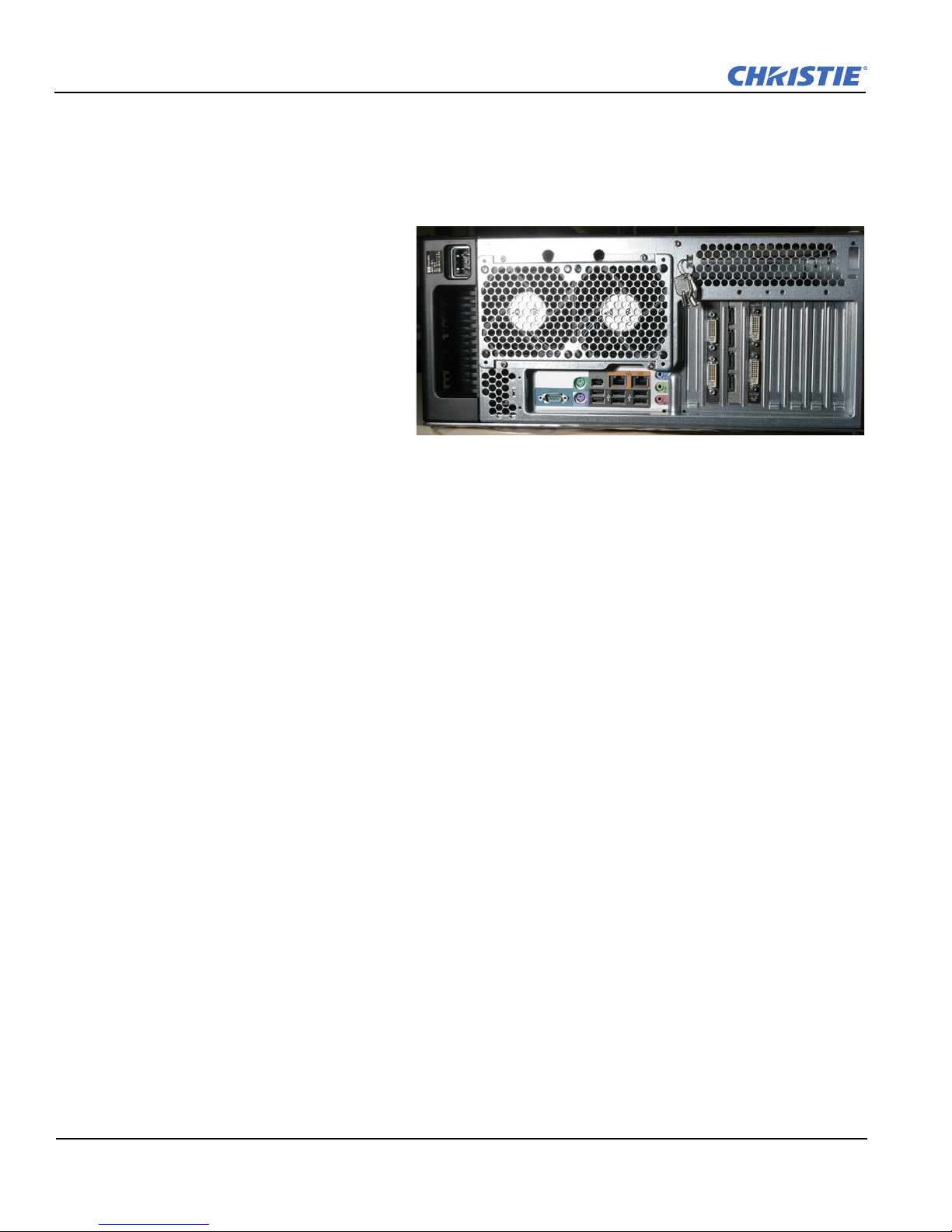
Figure 2-1 TVC-500 Main Chassis (Rear View)
2.2 Unpacking the TVC-500
2.2.1 TVC-500 Main Chassis
Main Box
• Controller (Figure 2-1) shown with
example module configuration installed
in expansion slots)
• Polyethylene Bag 1:
• Product registration card
• Start-up instruction sheet
• OS Recovery CD (Windows 7)
•MASTERSuite Software CD
•MASTERSuite User Manual
•MASTERSuite Installation Guide
• TVC-500 Hardware Setup Manual
• Keyboard
•Mouse
• One AC line cord
• Display port to DVI adapter (4 per D4C module)
• BNC breakout cables (1 per V8C module)
• DVI to VGA adapter (2 per D2R2-E module)
• DVI to Component adapter (1 per D2R2-E module)
• DVI to HDMI adapter (1 per D2R2-E module)
2-2 TVC-500 Operation Manual
020-100539-01 Rev. 1 (08-2010)

2.3 Component Identification
Figure 2-2 Front Panel Components
2.3.1 Front Panel Components
The following illustration (Figure 2-2) shows the front panel components of the TVC-500 chassis. Table 2.1
lists the components as numbered in Figure 2-2.
Section 2: Installation and Setup
Table 2.1 Front Panel Components
OPTICAL DISC DRIVE ACTIVITY
1
LIGHT
DVD+RW DRIVE
2
IEEE-1394A CONNECTOR
3
MICROPHONE CONNECTOR
4
HEADPHONE CONNECTOR
5
USB CONNECTORS 2.0 (3)
6
POWER BUTTON/POWER ON LIGHT
7
OPTICAL DISC DRIVE EJECT BUTTON
8
TVC-500 Operation Manual 2-3
020-100539-01 Rev. 1 (08-2010)

Section 2: Installation and Setup
Figure 2-3 Rear Panel Components
2.3.2 Rear Panel Components
The following illustration (Figure 2-3) shows the rear panel components the basic controller configuration.
Table 2.2 lists the components as numbered in Figure 2-3.
Table 2.2 Rear Panel Components
POWER CORD CONNECTOR 8CABLE LOCK SLOT
1
PS/2 MOUSE PORT/CONNECTOR 9SERIAL CONNECTOR
2
IEEE-1394 CONNECTOR 10 PS/2 KEYBOARD CONNECTOR (PURPLE)
3
RJ-45 NETWORK CONNECTOR (RIGHT HAND CONNECTOR IS
4
ASF)
AUDIO LINE-IN CONNECTOR (BLUE) 12 MICROPHONE CONNECTOR (PINK)
5
ACCESS PANEL KEY (LID) 13 AUDIO LINE-OUT CONNECTOR (GREEN)
6
7POWER SUPPLY LED
11 USB CONNECTORS (6)
2-4 TVC-500 Operation Manual
020-100539-01 Rev. 1 (08-2010)

2.4 RAID 1
2.4.1 Configurations
Redundant Array of Independent Disks (RAID) combines physical hard disks into a single logical unit.
The TVC-500 utilizes a hardware RAID solution and comes pre-configured with RAID 1.
Recognizing Hard Drive Failures
Hard drive failures are indicated by Power-On Self Test (POST) messages (see Section 5 Troubleshooting &
Figure 2-4) or the Intel® Matrix Storage Console (Figure 2-5).
Section 2: Installation and Setup
Figure 2-4 Hard Drive Failure Reported in POST
Figure 2-5 Hard Drive Failure Reported in Intel® Matrix Storage Console
TVC-500 Operation Manual 2-5
020-100539-01 Rev. 1 (08-2010)

Section 2: Installation and Setup
Effects of a Hard Drive Failure
If more hard drives fail than the fault tolerance method allows, the logical drive fails. In this case, you are
likely to lose data.
2.4.2 Disk Replacement - Automatic Rebuild
Degraded RAID 1 Volume
A RAID 1 volume is reported as 'Degraded' when one of its members fails or is disconnected and data
mirroring is lost. As a result, the system can only use the functional member. To re-establish data mirroring and
restore data redundancy, refer to the procedures below.
Missing Member Drive
1. Make sure the system is powered OFF.
2. Reconnect the missing hard drive.
3. Restart the system. The rebuild will occur automatically.
Failed Member Drive
1. Make sure the system is powered OFF.
2. Replace the failed hard drive with a new one that is of equal or greater capacity.
3. Power on the system. During the system startup, the Intel® Matrix Storage Manager option ROM user
Interface will display the RAID 1 volume status as 'Degraded' (Figure 2-4).
4. After the operating system is running, select Intel® Matrix Storage Console from the Start Menu or click
the Intel Matrix Storage Manager tray icon.
5. From the View menu (circled in Figure 2-5), select 'Advanced Mode' to see a detailed view of device
storage information.
6. In the device pane, right-click on the new non-RAID hard drive and select 'Rebuild to this Hard Drive'.
Click on the RAID 1 volume in the device pane. The status in the information pane will display 'Rebuilding: %
complete'. After the rebuild is complete, the status will display 'Normal'.
2-6 TVC-500 Operation Manual
020-100539-01 Rev. 1 (08-2010)
3 Connecting the Controller
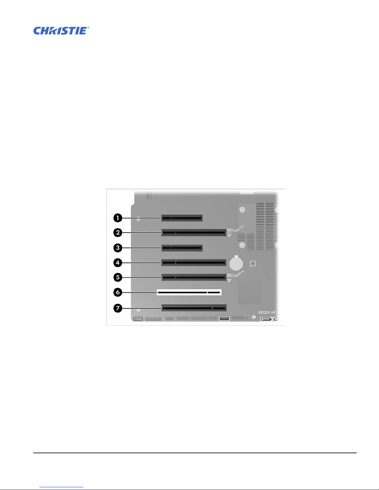
Figure 3-1 TVC-500 Card Slots (Top Inside View)
This section discusses how to prepare your controller for operation. It provides a detailed look at the controller
chassis and its various components, instructions on how to connect various sources and how to power the
controller.
3.1 Input Channel and Display Numbering for TVC-500
Channel numbering refers to the position of the cards in the TVC-500. The following diagrams illustrate how
the cards installed in the TVC-500 translate to channels in MASTERSuite.
NOTE: Card positions 1 to 7, with the exception of 6, are PCIe slots. Position 6 is PCI.
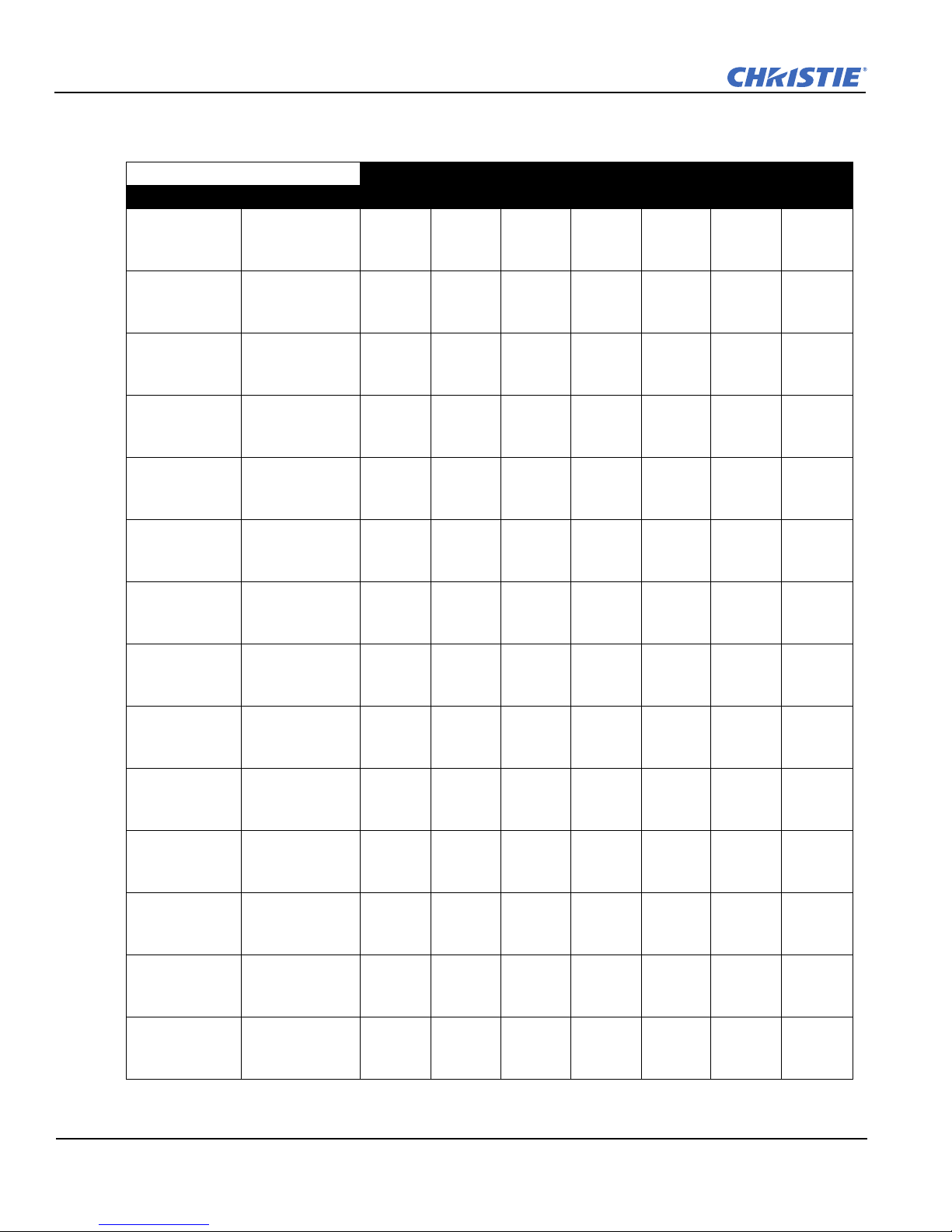
Tab le 3. 1 provides the preferred positions for the three primary module types, along with the channel
assignment ranges. The system can accommodate up to 2 V8C modules, up to 3 D4C modules and up to 2
D2R2-E modules.
Channel Reference
D4C 1 = Channels 1 – 4 V8C 1 = Channels 1 – 16 D2R2-E 1 = Channels 1 - 2
D4C 2 = Channels 5 – 8 V8C 2 = Channels 17 – 32 D2R2-E 2 = Channels 3 - 4
D4C 3 = Channels 9 - 12
TVC-500 Operation Manual 3-1
020-100539-01 Rev. 1 (08-2010)
Section 3: Connecting the Controller
Table 3.1 Module Positions & Channel Numbers
Part # Configuration Slot 1 Slot 2 Slot 3 Slot 4 Slot 5 Slot 6 Slot 7
128-001102-01 4 Display Out,
8 Video In,
0 DVI/RGB In
128-002103-01 4 Display Out,
16 Video In,
0 DVI/RGB In
128-003104-01 4 Display Out,
8 Video In,
2 DVI/RGB In
128-004105-01 4 Display Out,
16 Video In,
2 DVI/RGB In
128-005106-01 4 Display Out,
16 Video In,
4 DVI/RGB In
128-006107-01 8 Display Out,
8 Video In,
0 DVI/RGB In
128-007108-01 8 Display Out,
16 Video In,
0 DVI/RGB In
128-008109-01 8 Display Out,
8 Video In,
2 DVI/RGB In
128-009100-01 8 Display Out,
16 Video In,
2 DVI/RGB In
128-010102-01 8 Display Out,
16 Video In,
4 DVI/RGB In
128-011103-01 12 Display Out,
8 Video In,
0 DVI/RGB In
128-012104-01 12 Display Out,
16 Video In,
0 DVI/RGB In
128-013105-01 12 Display Out,
8 Video In,
4 DVI/RGB In
128-014106-01 12 Display Out,
8 Video In,
2 DVI/RGB In
Not
Used
V8C
1
V8C
1
V8C
1
V8C
1
V8C
1
V8C
1
V8C
1
V8C
1
V8C
1
V8C
1
V8C
1
V8C
1
V8C
1
D4C
1
D4C
1
D4C
1
D4C
1
D4C
1
D4C
1
D4C
1
D4C
1
D4C
1
D4C
1
D4C
1
D4C
1
D4C
1
D4C
1
Module & Channel #
Not
Used
V8C
2
Not
Used
V8C
2
V8C
2
Not
Used
V8C
2
Not
Used
V8C
2
V8C
2
Not
Used
V8C
2
D2R2-
E
V8C
1
Not
Used
D2R2-E
1
Not
Used
Not
Used
D4C
2
D4C
2
D4C
2
D4C
2
D4C
2
D4C
2
D4C
2
D4C
2
1
Not
Used
D4C
2
Not
Used
Not
Used
Not
Used
Not
Used
D2R2-
E
1
Not
Used
Not
Used
Not
Used
Not
Used
D2R2-
E
1
D4C
3
D4C
3
D4C
3
D4C
3
Not
Used
Not
Used
Not
Used
Not
Used
Not
Used
Not
Used
Not
Used
Not
Used
Not
Used
Not
Used
Not
Used
Not
Used
Not
Used
Not
Used
Not
Used
Not
Used
Not
Used
D2R2-E
1
D2R2-E
2
Not
Used
Not
Used
D2R2-E
1
D2R2-E
1
D2R2-E
2
Not
Used
Not
Used
D2R2-E
2
D2R2-E
1
3-2 TVC-500 Operation Manual
020-100539-01 Rev. 1 (08-2010)
3.2 Connecting Devices to the TVC-500
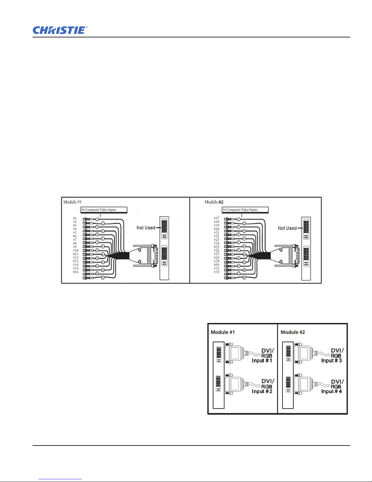
Figure 3-2 V8C Connections
Figure 3-3 D2R2-E Module
Input and display modules can be installed in the TVC-500.
3.2.1 About Source Connections
The controller comes pre-configured. You should be able to connect your sources and display content on the
display wall when the unit is unpacked. This section provides a high-level overview of the capabilities of the
modules available for this controller. It also touches on some system configuration information. All Input and
Display modules are clearly labeled.
V8C Module
The V8C module is installed into the controller to allow connection of composite sources. A single V8C
module has 16 built-in decoders, but only 8 are available at a time through the module’s bottom connector. The
top connector is designated for audio input, but is not used. Composite video can be connected to any of the
available BNC inputs. Refer to Figure 3-2.
A maximum of 2 V8C modules can be installed in the TVC-500.
Section 3: Connecting the Controller
D2R2-E Module
A maximumof 2 D2R2-E modules can be installed
into a TVC-500. This module provides both analog
component (RGB) and digital (DVI) inputs Figure 3-
3. For channel configuration refer to Figure 3-1 and
Tab le 3. 1. Each D2R2-E has 2 connectors. An RGB or
DVI source connected to the top connector is
considered Input 1.
If one of the D2R2-E modules is replaced, ensure that
the jumper settings of the new module matches the
jumper settings of the replaced module.
TVC-500 Operation Manual 3-3
020-100539-01 Rev. 1 (08-2010)

Section 3: Connecting the Controller
Figure 3-4 D2R2-E Jumper J6 Settings for Card Ordering
Figure 3-5 Display Port to DVI Adapters
The jumper setting equivalents are as follows:
• Jumper setting #1 in Figure 3-4 (all jumpers on) make this module input channels 1 and 2
• Jumper setting #2 (Least Significant Bit jumper removed) makes that module input channels 3 and 4, etc.
3.3 Connecting Display Devices/Screens for TVC-500
The controller comes standard with 1 D4C display
module and 4 Display Port to DVI Adapters
(Figure 3-5). In this configuration, the controller
can be connected to up to 4 display devices. The
controller can have up to 3 D4C modules, enabling
you to configure up to 12 display devices.
3-4 TVC-500 Operation Manual
020-100539-01 Rev. 1 (08-2010)

Section 3: Connecting the Controller
Figure 3-6 USB Ports Connections (Rear Panel)
DVI-D Cables
When connecting DVI-D cables, the controller and Display devices must be powered down. DVI-D
connection requires Extended Display Identification Data (EDID), which is detected at startup.
1. Connect the smaller connector of each of the Display Port to DVI Adapter cables to the display module
connectors on the rear panel (Figure 3-5).
2. Connect the other end of each cable to a DVI extension cable (not supplied). Connect the extension cable
to your display devices in any convenient order.
3. Power up the display devices.
4. Power up the Controller. An application will open that allows the user to configure the display devices. For
details, refer to Section 3.5.1 Power ON Controller.
No DVI signal
If you do not see output on any of the display devices, it is possible there is a problem with the EDID.
1. Power down the Controller. For details, refer to Section 3.5.2 Power OFF Controller.
2. Change cables or re-seat connectors.
3. Power up the Controller and confirm the configuration is correct.
3.4 Connecting Peripheral Devices
1. Connect the keyboard and mouse to
any of the USB ports (within dashed
rectangle in Figure 3-6 or the 3 ports
on the front panel in Figure 3-8).
2. Connect CAT5 Ethernet cable(s)
(circled in Figure 3-6). This step is
only required if you are connecting to
1 or more networks.
3. Connect any peripheral devices, such
as USB or serial components, to the
appropriate connectors on the rear
and/or front panel.
TVC-500 Operation Manual 3-5
020-100539-01 Rev. 1 (08-2010)
 Loading...