

Christie TVC-1211 User Manual

TVC-1211
USER MANUAL
020-100769-01


TVC-1211
USER MANUAL
020-100769-01

NOTICES
COPYRIGHT AND TRADEMARKS
© 2011-2012 Christie Digital Systems USA, Inc. All rights reserved.
All brand names and product names are trademarks, registered trademarks or trade names of their respective holders.
REGULATORY
The product has been tested and found to comply with the limits for a Class A digital device, pursuant to Part 15 of the FCC Rules.
These limits are designed to provide reasonable protection against harmful interference when the product is operated in a
commercial environment. The product generates, uses, and can radiate radio frequency energy and, if not installed and used in
accordance with the instruction manual, may cause harmful interference to radio communications. Operation of the product in a
residential area is likely to cause harmful interference in which case the user will be required to correct the interference at the
user’s own expense.
This Class A digital apparatus complies with Canadian ICES-003.
Cet appareil numérique de la classe A est conforme à la norme NMB-003 du Canada.
이 기기는 업무용 (A 급 ) 으로 전자파적합등록을 한 기기이오니 판매자 또는 사용자는 이점을 주의하시기 바라며 , 가정 외의 지역에서
사용하는 것을 목적으로 합니다 .
GENERAL
Every effort has been made to ensure accuracy, however in some cases changes in the products or availability could occur which
may not be reflected in this document. Christie reserves the right to make changes to specifications at any time without notice.
Performance specifications are typical, but may vary depending on conditions beyond Christie's control such as maintenance of
the product in proper working conditions. Performance specifications are based on information available at the time of printing.
Christie makes no warranty of any kind with regard to this material, including, but not limited to, implied warranties of fitness for
a particular purpose. Christie will not be liable for errors contained herein or for incidental or consequential damages in
connection with the performance or use of this material.
The product is designed and manufactured with high-quality materials and components that can be recycled and reused. This
symbol means that electrical and electronic equipment, at their end-of-life, should be disposed of separately from regular
waste. Please dispose of the product appropriately and according to local regulations. In the European Union, there are separate
collection systems for used electrical and electronic products. Please help us to conserve the environment we live in!
Canadian manufacturing facility is ISO 9001 and 14001 certified.
GENERAL WARRANTY STATEMENTS
For complete information about Christie’s limited warranty, please contact your Christie dealer. In addition to the other limitations
that may be specified in Christie’s limited warranty, the warranty does not cover:
a. Damage occurring during shipment, in either direction.
b. Projector lamps (See Christie’s separate lamp program policy).
c. Damage caused by use of a projector lamp beyond the recommended lamp life, or use of a lamp supplied by a supplier other
than Christie.
d. Problems caused by combination of the product with non-Christie equipment, such as distribution systems, cameras, video
tape recorders, etc., or use of the product with any non-Christie interface device.
e. Damage caused by misuse, improper power source, accident, fire, flood, lightning, earthquake or other natural disaster.
f. Damage caused by improper installation/alignment, or by product modification, if by other than a Christie authorized repair
service provider.
g. For LCD projectors, the warranty period specified applies only where the LCD projector is in “normal use.” “Normal use”
means the LCD projector is not used more than 8 hours a day, 5 days a week. For any LCD projector where “normal use” is
exceeded, warranty coverage under this warranty terminates after 6000 hours of operation.
h. Failure due to normal wear and tear.
PREVENTATIVE MAINTENANCE
Preventative maintenance is an important part of the continued and proper operation of your product. Please see the
Maintenance section for specific maintenance items as they relate to your product. Failure to perform maintenance as required,
and in accordance with the maintenance schedule specified by Christie, will void the warranty.

Table of Contents
1: Introduction
1.1 Labels and Marking.....................................................................................................................1-1
1.2 Related Documents......................................................................................................................1-1
1.3 Safety Information.......................................................................................................................1-1
1.3.1 Prevent Electrostatic Discharge...........................................................................................1-1
1.3.2 Installation Guidelines.........................................................................................................1-2
Elevated Ambient Temperature ............................................................................................ 1-2
Reduced Air Flow .................................................................................................................1-2
Mechanical Loading .............................................................................................................1-2
Circuit Overloading ..............................................................................................................1-2
Reliable Grounding ...............................................................................................................1-2
Grounding the Expansion Chassis ........................................................................................1-2
2: Hardware
2.1 Overview .....................................................................................................................................2-1
2.1.1 Key Features........................................................................................................................2-1
2.2 Unpacking....................................................................................................................................2-2
2.2.1 TVC-1211 Main Chassis .....................................................................................................2-2
Main Box ..............................................................................................................................2-2
TVC Expansion Chassis .......................................................................................................2-2
2.3 Purchase Record and Servicing...................................................................................................2-3
2.4 Component Identification............................................................................................................2-3
2.4.1 Main Chassis Front Panel Components...............................................................................2-3
2.4.2 Main Chassis Front Panel LEDS and Buttons.....................................................................2-4
2.4.3 Main Chassis Rear Panel Components................................................................................2-5
2.4.4 Rear Panel Chassis LEDS....................................................................................................2-6
2.5 Redundant Array of Independent Disks (RAID).........................................................................2-7
2.5.1 Configurations .....................................................................................................................2-7
Recognizing Hard Drive Failures .........................................................................................2-7
Effects of Hard Drive Failures ..............................................................................................2-7
2.6 Disk Replacement - Automatic Rebuild......................................................................................2-7
3: Connecting the Controller
3.1 Grounding the Expansion Chassis...............................................................................................3-1
3.2 Connecting the Expansion Chassis to the Controller ..................................................................3-1
3.2.1 Connecting Multiple 13-slot Chassis...................................................................................3-2
3.2.2 Connecting Multiple 16-slot Expansion Chassis.................................................................3-3
3.3 Input Channel and Display Numbering.......................................................................................3-4
3.3.1 13-slot Expansion Chassis Channel Numbering..................................................................3-4
3.3.2 16-slot Expansion Chassis Channel Numbering..................................................................3-5
3.4 Connect Devices..........................................................................................................................3-5
3.4.1 About Source Connections ..................................................................................................3-5
Composites and S-Video Sources .........................................................................................3-5
V16A Module .......................................................................................................................3-6
D2R2 Module .......................................................................................................................3-6
TVC-1211 User Manual i
020-100769-01 Rev. 4 (05-2012)

Table of Contents
3.5 Connecting Display Devices/Screens..........................................................................................3-7
3.5.1 VGA Cables.........................................................................................................................3-7
3.5.2 DVI-D Cables ......................................................................................................................3-7
3.5.3 No DVI Signal .....................................................................................................................3-8
3.6 Connecting Peripheral Devices....................................................................................................3-8
3.7 Connecting Power........................................................................................................................3-9
3.7.1 Connect AC Line Cords to TVC-1211 Controller...............................................................3-9
3.7.2 Connect AC Line Cords to Expansion Chassis....................................................................3-9
3.8 Powering ON/OFF.......................................................................................................................3-9
3.8.1 Power ON Expansion Chassis..............................................................................................3-9
3.8.2 Power ON Controller ...........................................................................................................3-10
3.8.3 Power OFF........................................................................................................................... 3-10
3.9 System Monitoring ......................................................................................................................3-11
3.9.1 Monitoring Controller Components.....................................................................................3-11
3.9.2 Monitoring Hard Disk Drives ..............................................................................................3-12
3.9.3 Recognizing Hard Drive Failures ........................................................................................3-13
3.9.4 Monitoring Expansion Chassis Power Supplies ..................................................................3-13
3.9.5 Recognizing Expansion Chassis Power Supply Failures.....................................................3-13
3.10 Network Adapter Teaming ........................................................................................................3-13
4: Specifications
4.1 Hardware......................................................................................................................................4-1
4.1.1 Main Chassis........................................................................................................................4-1
4.1.2 Main Memory ......................................................................................................................4-1
4.1.3 I/O Interfaces........................................................................................................................4-1
4.1.4 Integrated SATA Storage Controller ...................................................................................4-2
4.1.5 Embedded PCI Express Gigabit NIC Server Adapter .........................................................4-2
4.1.6 Expansion Chassis (16-Slot)................................................................................................ 4-2
4.1.7 Expansion Chassis (13-Slot)................................................................................................ 4-2
4.2 Power Requirements....................................................................................................................4-3
4.2.1 Main Chassis........................................................................................................................4-3
4.2.2 Expansion Chassis................................................................................................................4-3
4.3 Storage .........................................................................................................................................4-4
4.3.1 Peripheral Devices ...............................................................................................................4-4
4.4 TVC-1211 Display/Video Architecture.......................................................................................4-5
4.4.1 Graphics Output (D4A)........................................................................................................4-5
4.4.2 D4A Resolution Versus Frequency......................................................................................4-6
4.5 Input (Source Signal) Compatibility............................................................................................4-7
4.5.1 Video Input (V16A).............................................................................................................4-7
16-Port Multiple Video Input Module (V16A) .....................................................................4-7
Composite and S-Video Input ...............................................................................................4-7
4.5.2 Standard Input VGA Connectors (D2R2)............................................................................4-7
4.5.3 DVI Input (D2R2)................................................................................................................4-8
4.6 Regulatory....................................................................................................................................4-8
4.6.1 Safety ...................................................................................................................................4-8
4.6.2 EMC.....................................................................................................................................4-8
ii TVC-1211 User Manual
020-100769-01 Rev. 4 (05-2012)

Table of Contents
4.6.3 Certification Marks..............................................................................................................4-9
4.7 Reliability and Serviceability ......................................................................................................4-9
4.8 Quality .........................................................................................................................................4-9
4.9 Environment ................................................................................................................................4-10
4.9.1 Operating ............................................................................................................................4-10
4.9.2 Non-Operating....................................................................................................................4-10
Storage ..................................................................................................................................4-10
Shipping ................................................................................................................................4-10
TVC-1211 User Manual iii
020-100769-01 Rev. 4 (05-2012)

1 Introduction
1.1 Labels and Marking
Observe and follow any warnings and instructions marked on the controller.
Danger symbols indicate a hazardous situation which, if not avoided, will result
in death or serious injury. This signal word is to be limited to the most extreme situations.
Warning symbols indicate a hazardous situation which, if not avoided, could
result in death or serious injury.
Caution symbols indicate a hazardous situation which, if not avoided, could
result in minor or moderate injury.
NOTICE: Addresses practices not related to personal injury.
1.2 Related Documents
MASTERSuite User Manual (P/N: 020-100563-xx)
1.3 Safety Information
Review this section before attempting to service the TVC-1211 controller.
1.3.1 Prevent Electrostatic Discharge
Electrostatic discharge (ESD) can damage electronic components. ESD damage can shorten a component's life
expectancy or render it useless.
The following precautions can reduce the risk of ESD damage to components:
• Ground yourself properly when working with a static-sensitive component or assembly.
• If possible, work on a grounded surface.
• Keep electrostatic-sensitive components in their static-safe packaging until you are ready to install.
• Always avoid touching pins, leads or circuitry.
TVC -1211 User Manual 1-1
020-100769-01 Rev. 4 (05-2012)
Section 1: Introduction
1.3.2 Installation Guidelines
Installation in a rack assembly is recommended for this product. Carefully read the following guidelines to
ensure the TVC-1211 can maintain optimum operation.
Elevated Ambient Temperature
If installed in a closed or multi-unit rack assembly, the operating ambient temperature of the rack environment
may be greater than the ambient temperature of the room. Therefore, consideration should be given to
installing the equipment in an environment compatible with the maximum ambient temperature of 35°C
(95°F).
Reduced Air Flow
Maintain unrestricted airflow around the installed equipment at all times. For rack installation, it is
recommended to leave a minimum of 1U (1.75”/44.45 mm) above the expansion chassis
Mechanical Loading
A void uneven mechanical loading to minimize possible hazardous conditions when mounting the equipment in
a rack.
Circuit Overloading
Ensure the equipment is properly connected to the supply circuit and follow equipment ratings to avoid circuit
overloading.
Reliable Grounding
Reliable grounding of rack-mounted equipment should be maintained. Particular attention should be given to
supply connections rather than direct connections to the branch circuit (e.g., use of power strips).
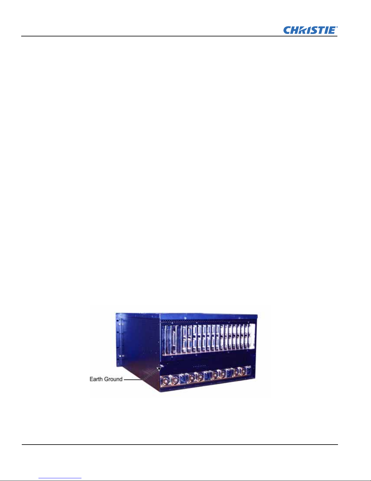
Grounding the Expansion Chassis
The expansion chassis must be connected to a reliable earth ground and installed in accordance with local
electrical safety standards.
1-2 TVC -1211 User Manual
020-100769-01 Rev. 4 (05-2012)
Section 1: Introduction
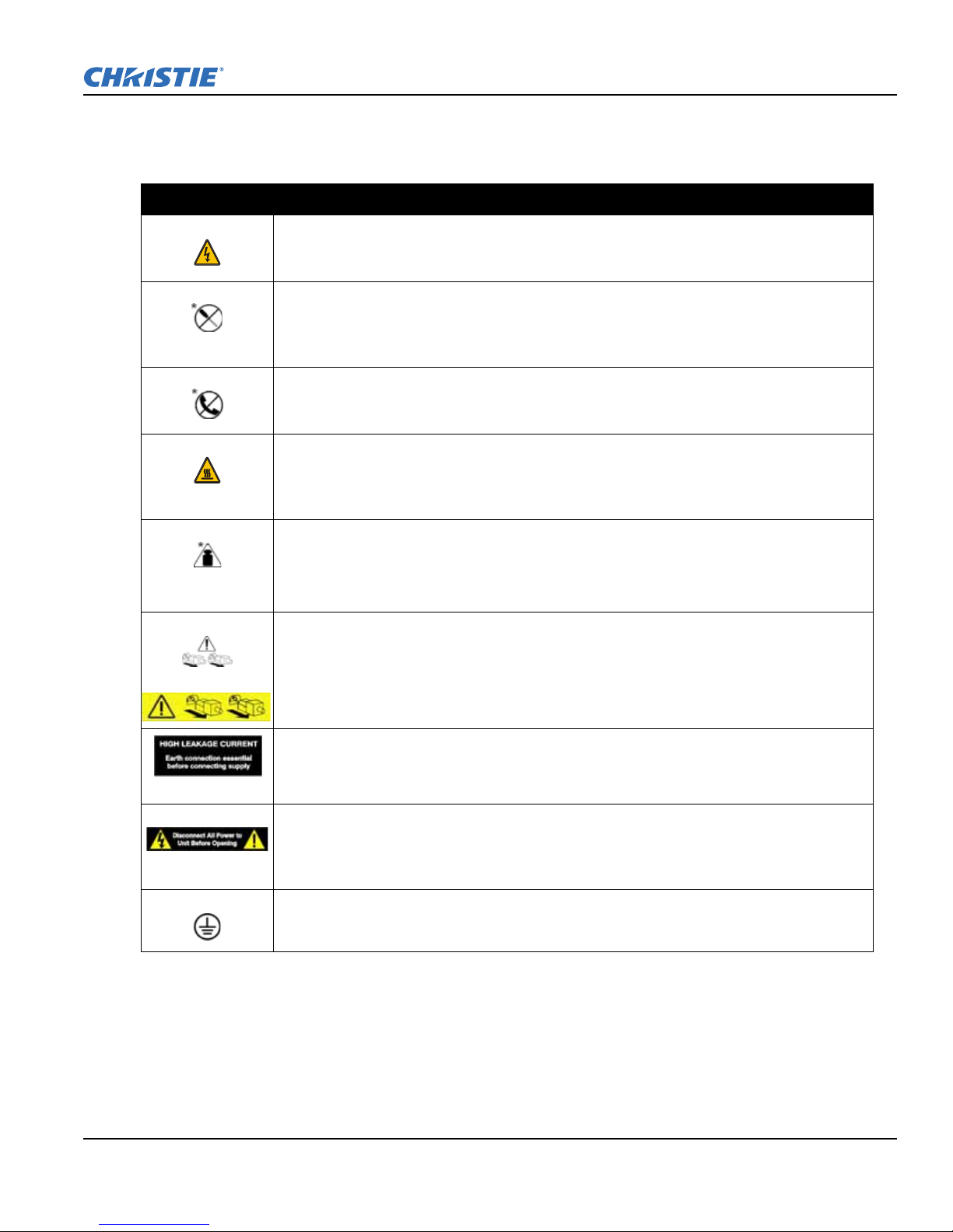
Warning/Hazard Labels and Symbols for Controller and Expansion Chassis
Observe and follow all warnings and instructions marked on the chassis, the components in the controller and
expansion chassis, and in all related documents. The following symbols indicate potential hazards.
This symbol indicates the presence of hazardous energy circuits or electrical shock hazards.
WARNING! To reduce the risk of injury from electrical shock hazards, do not open this
enclosure. Refer all maintenance, upgrades and servicing to qualified personnel.
This symbol indicates that the area contains no user or field serviceable parts and electrical
shock hazards may be present.
WARNING! To reduce the risk of injury from electrical shock hazards, do not open this
enclosure.
This symbol on an RJ-45 receptacle indicates a network interface connection.
WARNING! To reduce the risk of electric shock, fire, or damage to the equipment, do not
plug telephone or telecommunications connectors into this receptacle.
This symbol indicates the presence of a hot surface or hot component. Contact with the hot
surface may cause personal injury.
WARNING! To reduce the risk of injury from a hot component, allow the surface to cool
before touching.
This symbol indicates the component exceeds the recommended weight that one person may
handle safely.
24-41 kg
55-90 lbs
WARNING! To reduce the risk of personal injury or damage to the equipment, observe local
occupational health and safety requirements and guidelines for manual material handling.
These symbols, on power supplies or systems, indicate the equipment is supplied by multiple
power sources.
WARNING! To reduce the risk of injury from electric shock, remove all power cords to
completely disconnect power from the system.
The power supplies combined exceed the 3.5mA touch current limit.
WARNING! The expansion chassis must be grounded using the grounding terminal.
This symbol indicates the presence of hazardous energy circuits or electric shock hazards.
WARNING! To reduce the risk of injury from electric shock hazards, remove all power cords
to completely disconnect power from the system. Refer all maintenance, upgrades and
servicing to qualified personnel.
This symbol indicates that you MUST connect the expansion chassis to a reliable earth
ground. The ground wire must be installed in accordance with local electrical safety
standards.
* © HP 2005
TVC -1211 User Manual 1-3
020-100769-01 Rev. 4 (05-2012)


2 Hardware
2.1 Overview
The TVC-1211 controller is a computer device that allows a user to control a display wall. Specially designed
wall management software enables the user to control and display several applications simultaneously on a
large, ultra-high resolution desktop. Each controller is pre-configured according to each customer's
specifications.
2.1.1 Key Features
• Rugged, industrial 19" rack mount form factor with front panel status LEDs
• 5U main chassis
• Multiple 6U expansion chassis, each with:
• 16-slot (8 PCI-X and 8 PCI) switch fabric backplane
or:
• 13-slot PCI backplane
• Cosmetic customizing for consistent look and feel of main and expansion chassis
• Redundant hot plug power supplies
• Redundant chassis cooling fans
®
•Intel
• 4GB of DDR3 SDRAM
• 500GB of redundant SATA hardware storage
• Integrated RAID support
• 2 Gigabit Ethernet ports
• 4 USB 2.0 ports
• 1 serial port
• 1 keyboard
• 2-button optical mouse with scroll wheel
• DVD +RW 16x drive
• Up to 48 display outputs
• Up to 16 simultaneous video windows per display output
• Up to 32 RGB windows
• System hardware and software monitoring
• Windows Server 2003 SE
• MASTERSuite 5.0
• >50 000 hours MTBF for all major hardware components
• <15 minutes MTTR for all major hardware components
Xeon™ Quad Core Processor
TVC-1211 User Manual 2-1
020-100769-01 Rev. 4 (05-2012)

Section 2: Hardware
2.2 Unpacking
2.2.1 TVC-1211 Main Chassis
Main Box
• Controller
• Accessories Box 1:
• Sliding rail rack mounting kit
• Accessories Box 2:
• Product registration card
• Start-up instruction sheet (Windows
• Operating System CD (Windows
• MASTERSuite Software CD
• MASTERSuite User Manual (P/N: 020-100563-xx)
• MASTERSuite Installation Guide (P/N: 020-100566-xx)
• TVC-1211 User Manual (P/N:020-100769-xx)
• Keyboard
•Mouse
• 1 AC line cord per power supply (2 per controller)
®
Server only)
®
Server)
• HP SmartStart CD (required for Windows reinstall)
TVC Expansion Chassis
• Expansion Chassis
• Accessories Box
• Sliding rail rack mounting kit
• 1 AC line cord per power supply (4 per chassis)
• Dual VGA splitter cables (2 per D4A module)
• Dual DVI-D splitter cables (2 per D4A module)
• Miscellaneous hardware (screws, etc.)
• Optional: BNC breakout cables (2 per V16A
module)
• Optional: VGA to DVI-1 adapters (2 per D2R2 module)
2-2 TVC-1211 User Manual
020-100769-01 Rev. 4 (05-2012)
 Loading...