

Page 1

User Guide
020-102993-01
Mirage SST
Page 2

NOTICES
COPYRIGHT AND TRADEMARKS
yright © 2019 Christie Digital Systems USA Inc. All rights reserved.
Cop
All brand names and product names are trademarks, registered trademarks or trade names of their respective holders.
GENERAL
Every effort has been made to ensure accuracy, however in some cases changes in the products or availability could occur which may not be reflected in this
document. Christie reserves the right to make changes to specifications at any time without notice. Performance specifications are typical, but may vary
depending on conditions beyond Christie's control such as maintenance of the product in proper working conditions. Performance specifications are based on
information available at the time of printing. Christie makes no warranty of any kind with regard to this material, including, but not limited to, implied
warranties of fitness for a particular purpose. Christie will not be liable for errors contained herein or for incidental or consequential damages in connection
with the performance or use of this material. Manufacturing facilities in Canada and China are ISO 9001 certified. Manufacturing facilities in Canada are also
ISO 14001 certified.
WARRANTY
Products are warranted under Christie’s standard limited warranty, the complete details of which are available by contacting your Christie dealer or Christie. In
addition to the other limitations that may be specified in Christie’s standard limited warranty and, to the extent relevant or applicable to your product, the
warranty does not cover:
Problems or damage occurring during shipment, in either direction.
a.
Problems or damage caused by combination of a product with non-Christie equipment, such as distribution systems, cameras, DVD players, etc., or use
b.
of a product with any non-Christie interface device.
Problems or damage caused by misuse, improper power source, accident, fire, flood, lightning, earthquake, or other natural disaster.
c.
Problems or damage caused by improper installation/alignment, or by equipment modification, if by other than Christie service personnel or a Christie
d.
authorized repair service provider.
Use of third party product enclosures for environmental protection during outside use must be approved by Christie.
e.
Problems or damage caused by use of a product on a motion platform or other movable device where such product has not been designed, modified or
f.
approved by Christie for such use.
Except where the product is designed for outdoor use, problems or damage caused by use of the product outdoors unless such product is protected from
g.
precipitation or other adverse weather or environmental conditions and the ambient temperature is within the recommended ambient temperature set
forth in the specifications for such product.
Defects caused by normal wear and tear or otherwise due to normal aging of a product.
h.
The warranty does not apply to any product where the serial number has been removed or obliterated. The warranty also does not apply to any product sold
by a reseller to an end user outside of the country where the reseller is located unless (i) Christie has an office in the country where the end user is located or
(ii) the required international warranty fee has been paid.
The warranty does not obligate Christie to provide any on site warranty service at the product site location.
PREVENTATIVE MAINTENANCE
Preventative maintenance is an important part of the continued and proper operation of your product. Failure to perform maintenance as required, and in
accordance with the maintenance schedule specified by Christie, will void the warranty.
REGULATORY
The product has been tested and found to comply with the limits for a Class A digital device, pursuant to Part 15 of the FCC Rules. These limits are designed
to provide reasonable protection against harmful interference when the product is operated in a commercial environment. The product generates, uses, and
can radiate radio frequency energy and, if not installed and used in accordance with the instruction manual, may cause harmful interference to radio
communications. Operation of the product in a residential area is likely to cause harmful interference in which case the user will be required to correct the
interference at the user’s own expense. Changes or modifications not expressly approved by the party responsible for compliance could void the user's
authority to operate the equipment
CAN ICES-3 (A) / NMB-3 (A)
이 기기는 업무용(A급)으로 전자파적합등록을 한 기기이오니 판매자 또는 사용자는 이점을 주의하시기 바라며, 가정 외의 지역에서 사용하는 것을 목적으로 합니다.
ENVIRONMENTAL
The product is designed and manufactured with high-quality materials and components that can be recycled and reused. This symbol
and electronic equipment, at their end-of
to local regulations. In the European Union, there are separate collection systems for used electrical and electronic products. Please help us to conserve the
environment we live in!
-life, should be disposed of separately from regular waste. Please dispose of the product appropriately and according
means that electrical
Page 3

Content
Introduction...................................................... 7
Third-part
Important safeguards.................................................7
Safety and warning guidelines......................................... 7
Installation safety and warning guidelines..................................8
AC power precautions...............................................9
Laser safety precautions.............................................9
Light intensity hazard distance........................................10
Product labels.....................................................12
General hazards................................................. 12
Mandatory action.................................................13
Electrical labels..................................................13
Laser labels....................................................13
Additional safety hazards............................................14
Product documentation...............................................14
Related documentation.............................................14
Projector overview..................................................15
Contact your dealer.................................................15
Key features......................................................15
How the projector works..............................................16
List of components..................................................16
Display panel components.............................................16
IR remote keypad..................................................18
y products................................................. 7
Operating the projector.............................................20
Performing initial system start-up........................................ 20
Turning on the system............................................. 22
Turning off the system............................................. 24
Projector LED status indicators........................................24
Projector LED shutter indicators....................................... 25
Adjusting the image............................................... 26
Selecting screen image orientation........................................26
Setting the image resize preset..........................................26
Mirage SST User Guide 3
020-102993-01 R
Copyright © 2019 Christie Digital Systems USA, Inc. All rights reserved.
ev. 1 (06-2019)
Page 4

Content
Adjusting lens settings...............................................26
Adjusting offset..................................................26
R
esetting the lens to home position.....................................27
Aligning the image with lens zoom and focus............................... 27
Locking the lens motor.............................................27
Determining what lens warnings are displayed.............................. 27
Adjusting primary colors..............................................28
DMD color correction................................................ 28
Adjusting color by precise chromaticity values...............................28
Adjusting color by saturation......................................... 29
Signal color correction............................................... 29
Adjusting the color space............................................29
Adjusting color by temperature........................................29
Selecting the color correction mode.....................................30
Correcting for ambient light..........................................30
Setting the frame delay...............................................30
Enabling film mode detect.............................................30
Adjusting the image sharpness..........................................31
Creating a seamless image with edge blending................................31
Adding edge blends to the projector.....................................31
Enabling basic edge blending.........................................31
Resetting edge blending............................................ 32
Geometry correction.................................................32
Enabling warping.................................................32
Correcting the shape of a keystoned image................................ 32
Configuring system settings.........................................35
Setting the date................................................... 35
Setting the time................................................... 35
Changing the splash screen............................................35
Determining the on-screen display position.................................. 35
Changing the language...............................................36
Changing the temperature units......................................... 36
Resuming projector operation after an AC power interruption.......................36
Keeping electronics on in standby mode.................................... 36
Enabling direct pass-through of HDMI, 3G, and DisplayPort input signals................37
Informing the source of signal preferences...................................37
Configuring the laser power settings.......................................37
Setting up 1D color uniformity.......................................... 38
Mirage SST User Guide 4
020-102993-01 R
Copyright © 2019 Christie Digital Systems USA, Inc. All rights reserved.
ev. 1 (06-2019)
Page 5

Content
Turning on the projector with low voltage....................................39
Configuring communications........................................40
Enabling projector communication........................................40
Setting the remote access lev
Communicating with Mirage SST through Art-Net...............................41
Art-Net channel listing............................................. 41
Index list for the input channel........................................43
Working with macros................................................45
Adding a macro..................................................45
Copying a macro.................................................45
Editing a macro..................................................46
Deleting a macro.................................................46
Configuring the GPIO................................................47
GPIO connector..................................................47
el..........................................40
Setting up projector profiles.........................................49
Creating a new projector profile......................................... 49
Importing a projector profile............................................49
Restoring settings from a profile.........................................49
Renaming a projector profile............................................50
Exporting a projector profile to an external device..............................50
Deleting a projector profile.............................................50
Backing up, restoring, and upgrading files..............................51
Upgrading the Mirage SST software.......................................51
Exporting backup settings to an external device............................... 51
Importing a file from an external device to restore settings........................ 52
Restoring projector default settings.......................................52
Diagnostic tools ..................................................53
Viewing Mirage SST information......................................... 53
Freezing an image..................................................53
Test patterns..................................................... 53
Selecting a test pattern.............................................53
Modifying grey level test pattern characteristics..............................54
Modifying ramp test pattern characteristics................................ 54
Modifying grid test pattern characteristics................................. 54
Enabling a specific test pattern color.....................................55
Mirage SST User Guide 5
020-102993-01 R
Copyright © 2019 Christie Digital Systems USA, Inc. All rights reserved.
ev. 1 (06-2019)
Page 6

Content
Selecting an engine test pattern....................................... 55
Viewing Mir
age SST status.............................................55
Running the Mirage SST interrogator...................................... 55
Identifying where alarm and trap messages are sent............................ 56
Setting the SNMP read community string..................................56
Configuring traps.................................................56
Defining a trap IP address...........................................56
Restoring factory default settings.........................................56
Regulatory...................................................... 58
Safety......................................................... 58
Electro-magnetic compatibility.......................................... 58
Emissions..................................................... 58
Immunity..................................................... 58
Environmental.................................................... 58
Mirage SST User Guide 6
020-102993-01 R
Copyright © 2019 Christie Digital Systems USA, Inc. All rights reserved.
ev. 1 (06-2019)
Page 7

Introduction
This manual is intended for professionally tr
systems.
Only Christie qualified technicians who are knowledgeable about the hazards associated with highvoltage, ultraviolet exposure, and the high temperatures generated by the projector are authorized to
assemble, install, and service the projector.
For complete Mirage SST product documentation and technical support, go to www.christiedigital.com.
ained operators of Christie high-brightness projection
Third-party products
This projector is certified to work only with certain specified third-party components. Use only Christie
approved third-party components with the projector. Using non-approved components with the
projector can lead to potential safety hazards and void the projector warranty.
For detailed safety information on third-party components, refer to the product documentation
provided by the manufacturer of the component.
Important safeguards
To prevent personal injury and to protect the device from damage, read and follow these safety
precautions.
Safety and warning guidelines
Read all safety and warning guidelines before installing or operating the projector.
This projector must be operated in an environment that meets the operating range specification. Use
only the attachments and/or accessories recommended by Christie. Use of others may result in the
risk of fire, shock, or personal injury.
Mirage SST User Guide 7
020-102993-01 R
Copyright © 2019 Christie Digital Systems USA, Inc. All rights reserved.
ev. 1 (06-2019)
Page 8
Introduction
Warning! If not a
• This product must be operated in an environment that meets the operating range as specified in
this document.
• Do not look directly into the lens when the light source is on. The extremely high brightness can
cause permanent eye damage.
• ELECTRICAL and BURN HAZARD! Use caution when accessing internal components.
• FIRE HAZARD! Keep hands, clothes, and all combustible material away from the concentrated
light beam of the projector.
• Keep fingers and other body parts away from the moving parts in the product. Tie back long
hair, and remove jewelry and loose clothing before manually adjusting the product.
• FIRE AND SHOCK HAZARD! Use only the attachments, accessories, tools, and replacement parts
specified by Christie.
• Do not operate the product without a lens installed.
• Always use a lens plug when installing or moving the product. This prevents contaminants from
entering the product.
• FIRE AND SHOCK HAZARD! Use only the attachments, accessories, tools, and replacement parts
specified by Christie.
Caution! If not a
• TRIP OR FIRE HAZARD! Position all cables where they cannot contact hot surfaces, be pulled, be
tripped over, or damaged by persons walking on or objects rolling over the cables.
voided, the following could result in death or serious injury.
voided, the following could result in minor or moderate injury.
Installation safety and warning guidelines
R
ead all safety and warning guidelines before installing the projector.
Warning! If not a
• Possible hazardous optical radiation emitted from this product. (Risk group 3)
• Christie products must be installed and serviced by Christie qualified technicians.
• Do not operate the product without all of its covers in place.
• A minimum of two people or appropriately rated lift equipment is required to safely lift, install,
or move the product.
• Always install safety straps when the frame and projector are installed overhead.
• Observe load ratings and applicable local safety codes.
• When installing the projector in portrait mode, the rigging device must have a sufficient load
rating, as identified in this manual.
• This product must be installed within a restricted access location not accessible by the general
public.
• Install the product so users and the audience cannot enter the restricted area at eye level.
• Only personnel who are trained on the precautions for the restricted access location can be
granted entry to the area.
• Only Christie qualified technicians are permitted to open product enclosures.
Caution! If not a
• ELECTRICAL and BURN HAZARD! Use caution when accessing internal components.
• Only Christie qualified technicians are authorized to use the tools provided in the toolbox.
voided, the following could result in death or serious injury.
voided, the following could result in minor or moderate injury.
Mirage SST User Guide 8
020-102993-01 R
Copyright © 2019 Christie Digital Systems USA, Inc. All rights reserved.
ev. 1 (06-2019)
Page 9
AC power precautions
R
ead all safety and warning guidelines before connecting to AC power.
Warning! If not a
• SHOCK HAZARD! Only use the AC power cord provided with the product or recommended by
Christie.
• FIRE AND SHOCK HAZARD! Do not attempt operation unless the power cord, power socket, and
power plug meet the appropriate local rating standards.
• SHOCK HAZARD! Do not attempt operation if the AC supply is not within the specified voltage
and current, as specified on the license label.
• SHOCK HAZARD! The AC power cord must be inserted into an outlet with grounding.
• SHOCK HAZARD! A dedicated, protected ground or earth wire must be installed on the product
by Christie qualified technicians or electricians before it can be connected to power.
• SHOCK HAZARD! Disconnect the product from AC before installing, moving, servicing, cleaning,
removing components, or opening any enclosure.
• Install the product near an easily accessible AC receptacle.
Caution! If not a
• FIRE HAZARD! Do not use a power cord, harness, or cable that appears damaged.
• FIRE OR SHOCK HAZARD! Do not overload power outlets and extension cords.
• SHOCK HAZARD! Power supply uses double pole/neutral fusing. Disconnect all power sources
before opening the product.
voided, the following could result in death or serious injury.
voided, the following could result in minor or moderate injury.
Introduction
Laser safety precautions
R
ead all safety and warning guidelines before operating the projector laser.
Warning! If not a
• LASER RADIATION HAZARD! This projector has an external Class 4 laser module. Never attempt
to disassemble or modify the laser module.
• Possible hazardous optical radiation emitted from this product. (Risk group 3)
• Only Christie qualified technicians who are knowledgeable about the hazards associated with
laser use, high-voltage, and high temperatures generated by the product are authorized to
assemble, install, and service the Christie Laser Projection System.
• RADIATION HAZARD! Use of controls or adjustments, or performing procedures other than those
specified may result in hazardous radiation exposure.
• Do not look directly into the lens when the light source is on. The extremely high brightness can
cause permanent eye damage.
• Do not operate the product without all of its covers in place.
• LASER RADIATION! Do not short the contact rings.
• Always keep a protective cap on disconnected fiber optic cables.
voided, the following could result in death or serious injury.
Mirage SST User Guide 9
020-102993-01 R
Copyright © 2019 Christie Digital Systems USA, Inc. All rights reserved.
ev. 1 (06-2019)
Page 10
Introduction
Light intensity hazard distance
This projector has been classified as Risk Group 3 as per the IEC 62471-5:2015 standard due to
possible hazardous optical and thermal r
Warning! If not a
• PERMANENT/TEMPORARY BLINDNESS HAZARD! No direct exposure to the beam must be
permitted. Class 1 Laser Product - Risk Group 3 according to IEC 60825-1:2014 and IEC
62471-5:2015.
• PERMANENT/TEMPORARY BLINDNESS HAZARD! Operators must control access to the beam
within the hazard distance or install the product at the height that prevents exposure of
spectators' eyes within the hazard distance. The hazard zone must be no lower than 2.5 meters
(US installations) or 2.0 meters (global installations) above any surface upon which any persons
are permitted to stand and the horizontal clearance to the hazard zone must be a minimum 1.0
meters.
• EXTREME BRIGHTNESS! Do not place reflective objects in the product light path.
voided, the following could result in serious injury.
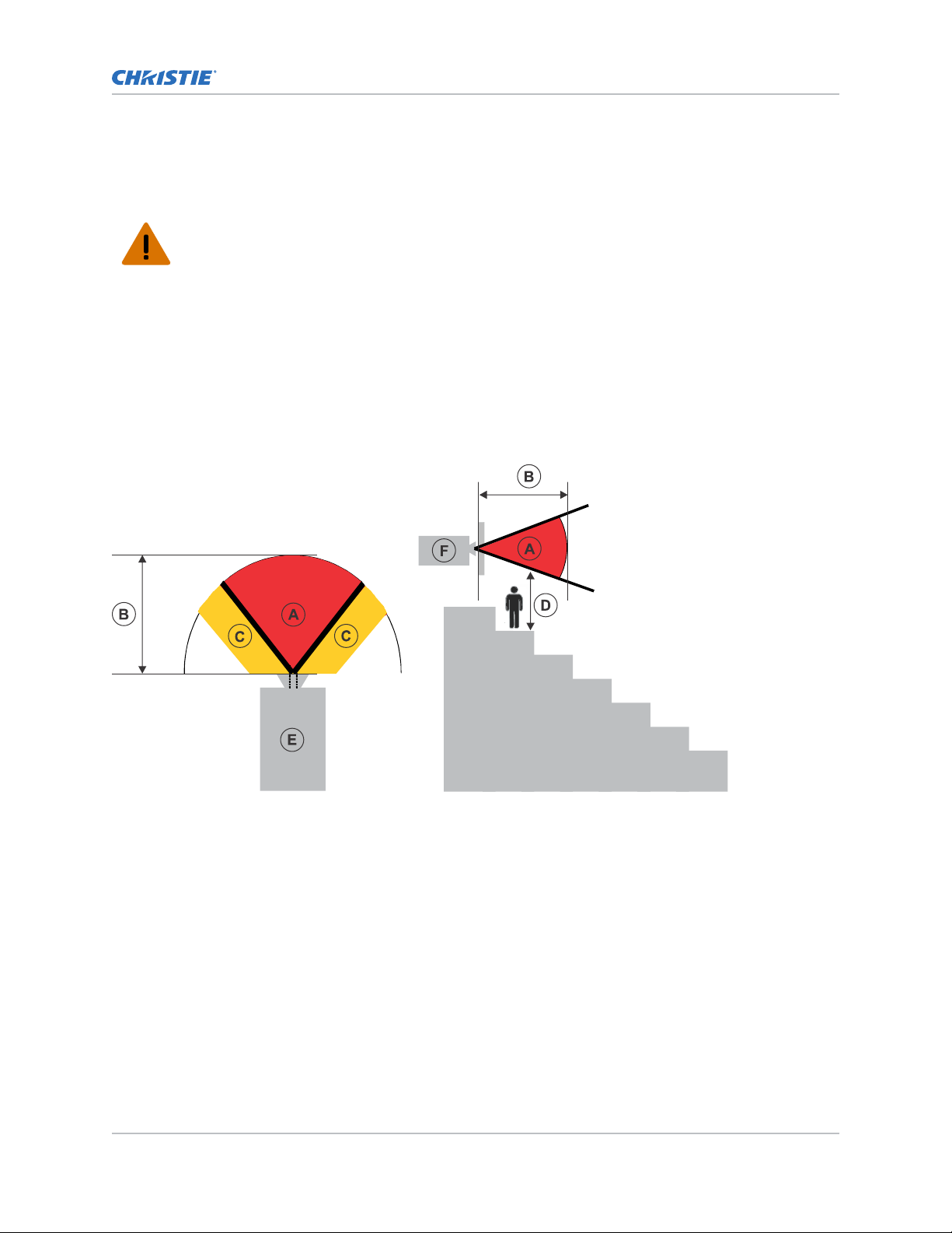
The following diagram and table show the zones for ocular and skin hazard distances:
adiation being emitted.
• A—Hazard zone. The region of space where the projection light from the laser-illuminated
projector is abo
ve emission limits for Risk Group 2. The light intensity may cause eye damage
after a momentary or brief exposure (before a person can avert his or her eyes away from the
light source). The light may cause skin burns to occur.
• B—Hazard distance. Operators must control access to the beam within the hazard distance or
install the product preventing potential exposure of the spectators' eyes from being in the
hazard distance.
• C—No access zone. Horizontal clearance of the no access zone must be a minimum of 1.0
meters.
• D—Vertical distance to hazard zone. The hazard zone must be no lower than 2.5 meters (US
installations) or 2.0 meters (global installations) above any surface upon which any persons
are permitted to stand.
• E—Represents the top view of the projector.
• F—Represents the side view of the projector.
Mirage SST User Guide 10
020-102993-01 R
Copyright © 2019 Christie Digital Systems USA, Inc. All rights reserved.
ev. 1 (06-2019)
Page 11

Introduction
For US and international hazard distances based upon IEC 62471-5:2015, Photobiological Safety of
Lamps and Lamp Systems – Part 5: Image Projectors.
Projection lens Part number Hazard distance
(m)
0.72:1 HB fixed 144-110103-XX 1
0.9:1 fixed lens 144-111014-XX 1.2
1.13-1.31:1 HB zoom 144-103105-XX 1.5
1.13-1.66:1 HB zoom 144-129103-XX 2.1
1.31-1.63:1 HB zoom 144-104106-XX 2.1
1.45-2.17:1 HB zoom 144-130105-XX 2.6
1.63-2.17:1 HB zoom 144-105107-XX 2.6
1.95-3.26:1 HB zoom 144-131106-XX 3.8
1.99-2.71:1 HB zoom 144-106108-XX 3.2
2.71-3.89:1 HB zoom 144-107109-XX 4.4
3.89-5.43:1 HB zoom 144-108100-XX 6.1
4.96-7.69:1 HB zoom 144-109101-XX 8.7
1.13-1.66 UHC zoom 163-118101-XX 1.8
1.45-2.17 UHC zoom 163-119102-XX 2.1
1.95-3.26 UHC zoom 163-120103-XX 3.2
For Installations in the United States
The following must be in place for laser
• Permanent show installations containing Risk Group 3 laser-illuminated projectors must meet
the following conditions:
• Installed by Christie or by Christie-authorized and trained installers.
Refer to the Laser Illuminated Projector - Class 1 Risk Group 3 Installation training (Course
code: CF-LIPI-01) on the http://www.christieuniversity.com site.
• Performed according to instructions provided by Christie.
• Ensure the projection system is securely mounted or immobilized to prevent unintended
movement or misalignment of the projections.
• The projection room shall be clearly identified by the posting of laser warning and restricted
access signs. The projection room sign must display the warning "Class 1 Risk Group 3 Laser
Controlled Area No Direct Exposure to Beam Shall be Permitted".
• The Christie Laser Projection System Installation Checklist must be fully completed after the
installation and sent to lasercompliance@christiedigital.com. A copy can remain on-site. This
checklist can be found as a separate document in the accessory box with the manual.
• If installing in the US states of Arizona, Florida, Georgia, Illinois, and Massachusetts, go to
www.christiedigital.com for additional regulatory requirements.
-illuminated projector installations in the United States:
Mirage SST User Guide 11
020-102993-01 R
Copyright © 2019 Christie Digital Systems USA, Inc. All rights reserved.
ev. 1 (06-2019)
Page 12
Product labels
Introduction
Learn about the labels that ma
y be used on the product. Labels on your product may be yellow or
black and white.
General hazards
Hazard warnings also apply to accessories once they are installed in a Christie product that is
connected to power.
Fire and Shock Hazard
To prevent fire or shock hazards, do not expose this product to rain or moisture.
Electrical Hazard
Do not alter the power plug, o
Do not remove the product enclosure.
Only Christie qualified technicians are authorized to service the product.
Risk of electric shock.
Do not remo
Only Christie qualified technicians are authorized to service the product.
General hazard.
ve the product enclosure.
verload the power outlet, or use it with extension cords.
Electric shock hazard. To avoid personal injury, disconnect all power sources before
performing maintenance or service.
Electrocution hazard. To avoid personal injury, always disconnect all power sources before
performing maintenance or service procedures.
Hot surface hazard. To avoid personal injury, allow the product to cool for the recommended
cool down time before performing maintenance or service.
Optical radiation hazard. To avoid personal injury, never look directly at the light source.
Moving parts hazard. To avoid personal injury, keep hands clear and loose clothing tied back.
Fan hazard. To avoid personal injury, keep hands clear and loose clothing tied back. Always
disconnect all power sources before performing maintenance or service procedures.
Laser hazard. To avoid personal injury, avoid eye or skin exposure to direct or scattered
adiations.
r
Mirage SST User Guide 12
020-102993-01 R
Copyright © 2019 Christie Digital Systems USA, Inc. All rights reserved.
ev. 1 (06-2019)
Page 13
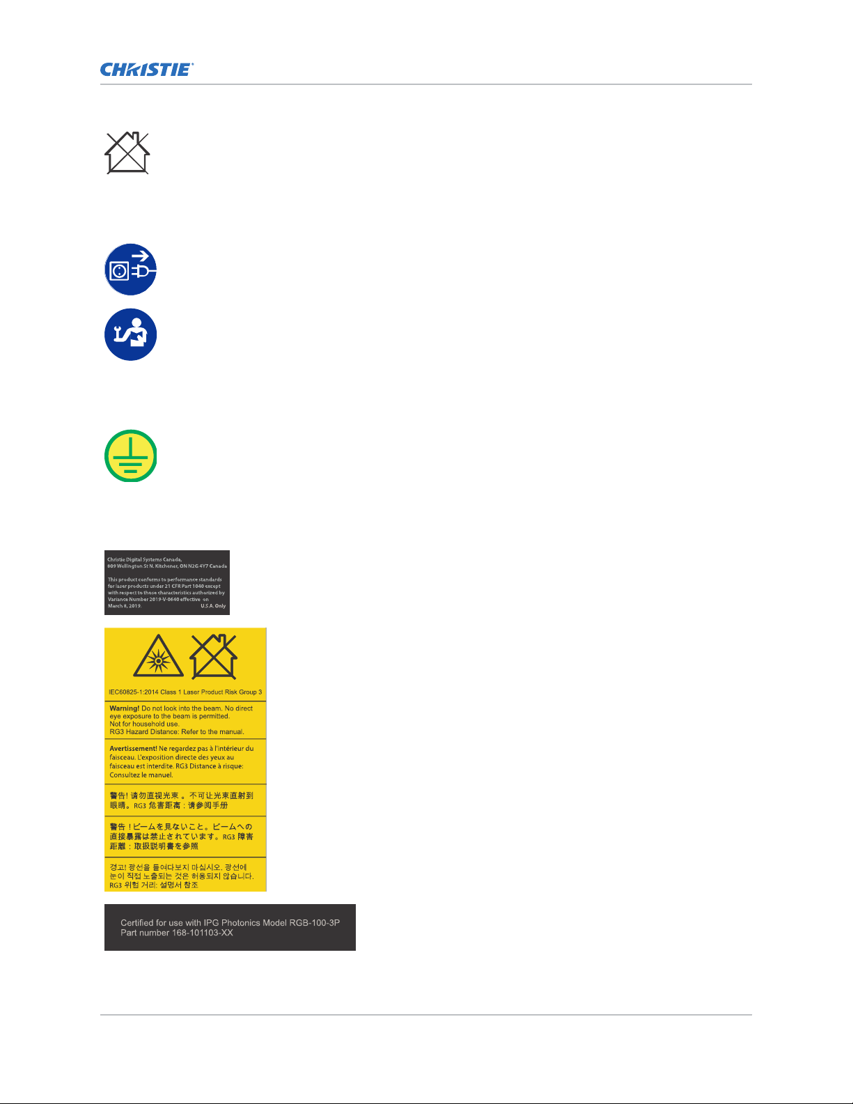
Not for household use.
Mandatory action
Disconnect all power sources before performing maintenance or service procedures.
Consult the service manual.
Electrical labels
Indicates the presence of a protective earth ground.
Introduction
Laser labels
FDA laser variance (US projectors only)
Indicates a light hazard. Do not look directly into the lens. The
extreme high brightness can cause permanent ey
Laser Product - Risk Group 3 according to IEC 60825-1: 2014 and
IEC 62471-5:2015
Indicates the product is certified for use with IPG Photonics Model
-100-3P Part number 168-101103-XX laser.
RGB
e damage. Class 1
Mirage SST User Guide 13
020-102993-01 R
Copyright © 2019 Christie Digital Systems USA, Inc. All rights reserved.
ev. 1 (06-2019)
Page 14
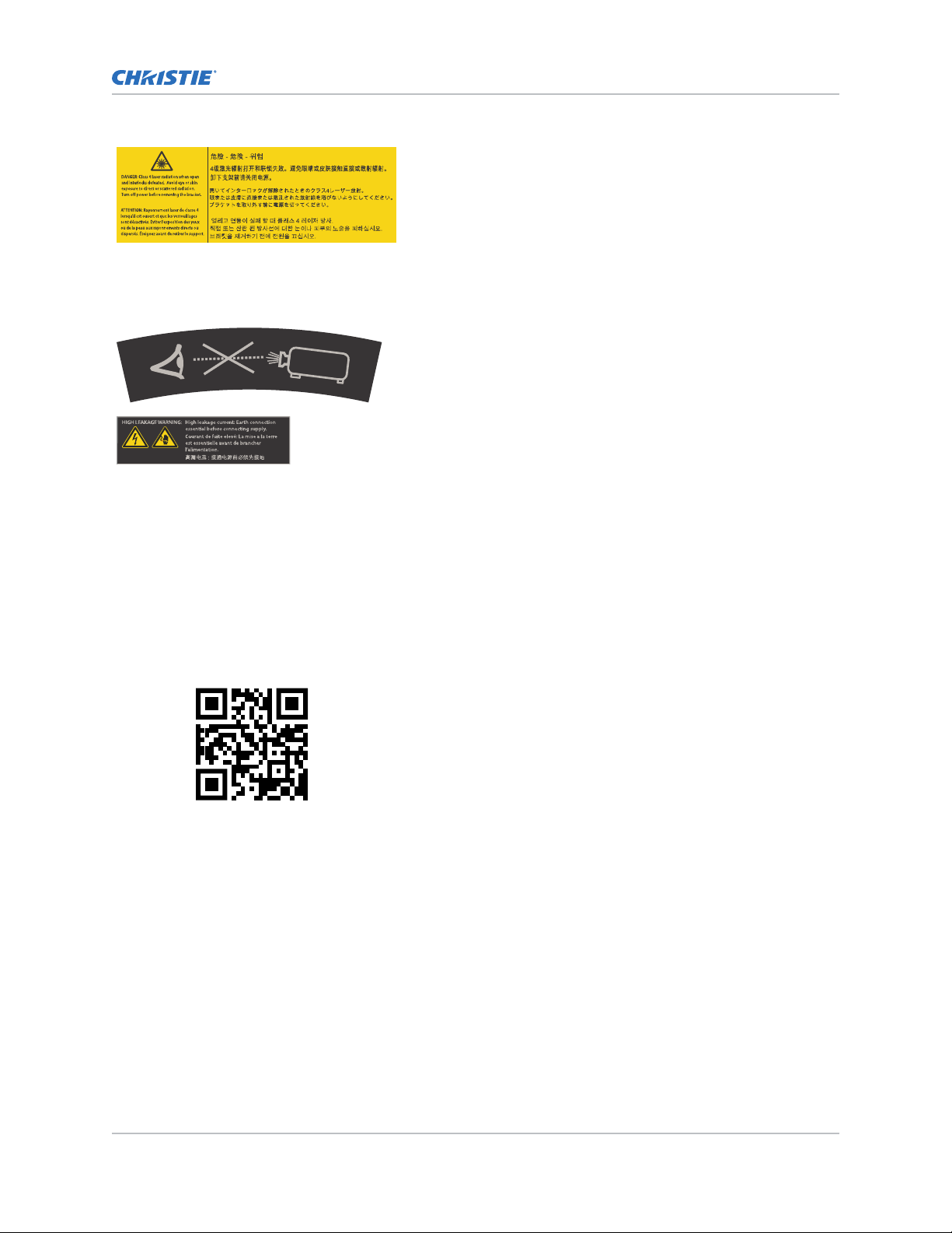
Indicates a danger Class 4 laser radiation when open and interlocks
are defeated. A
radiation. Turn off power before removing the bracket.
Additional safety hazards
Do not look directly into the lens. The extremely high brightness
can cause permanent eye damage.
Indicates high leakage current. Earth connection essential before
connecting the power supply
Product documentation
Introduction
void eye or skin exposure to direct or scattered
.
F
or installation, setup, and user information, see the product documentation available on the Christie
website. Read all instructions before using or servicing this product.
1. Access the documentation from the Christie website:
• Go to this URL: http://bit.ly/2TI2aEW or
https://www.christiedigital.com/en-us/3d/products-and-solutions/projectors/mirage-sst.
• Scan the QR code using a QR code reader app on a smartphone or tablet.
2. On the product page, switch to the Downloads
tab.
Related documentation
Additional information on this product is available in the following documents.
• Mirage SST Product Safety Guide (P/N: 020-102992-XX)
• Mirage SST Installation and Setup Guide (P/N: 020-102956-XX)
• Mirage SST Projector Head Specifications Guide (P/N: 020-102994-XX)
• Mirage SST Status System Guide (P/N: 020-103007-XX)
• Mirage SST Serial Commands Guide (P/N: 020-103005-XX)
• Mirage SST Projector Head Service Guide (P/N: 020-103039-XX)
Mirage SST User Guide 14
020-102993-01 R
Copyright © 2019 Christie Digital Systems USA, Inc. All rights reserved.
ev. 1 (06-2019)
Page 15

Projector overview
Introduction
Learn about the
Mirage SST is a professional quality projector using Digital Light Processing (DLPTM) technology from
Texas Instruments. Mirage SST is engineered specifically for complex, high-end applications like
planetariums, dome theaters, and theme park attractions to offer stunning wide screen, high
resolution 4K images at 120 frames per second.
Mirage SST provides several design and installation advantages. Its small form factor allows it to be
installed independently, or as part of a multi-projector array, into tight, challenging environments. The
remote light source also allows the chilling equipment to be located away from the projector head
where its noise will not impact the audience’s enjoyment of the show.
Mirage SST projector.
Contact your dealer
Record the information about your projector and keep this information with your records to assist with
the servicing of your projector. If you encounter a problem with your Christie projector, contact your
dealer.
Purchase record
Dealer:
Dealer or Christie Sales/Service contact phone number:
Projector serial number:
The serial number can be found on the license label located on the displa
Purchase date:
y panel
Installation date:
Ethernet settings
Default gateway
Projector IP address
Subnet mask
Key features
Understand the important features of the projector
• Built in warp and blend of projected images
• Improved lens mount with bayonet style insertion
• Single phase 100-240 V
• Side access to optical adjustments
• 4K resolution for flexibility and future proofing
• Omnidirectional operation
• TruLife electronics
.
Mirage SST User Guide 15
020-102993-01 R
Copyright © 2019 Christie Digital Systems USA, Inc. All rights reserved.
ev. 1 (06-2019)
Page 16

Introduction
• LCD display to provide information at-a-glance
How the projector works
The
Mirage SST accepts a variety of input signals for projection on front or rear projection screens,
typical in commercial or other large screen applications.
High-brightness light is generated by a laser illumination source, then fed to the projector through a
fiber optic cable, where it is modulated by three Digital Micromirror Device (DMD) panels responding
to incoming data streams of digitized red, green and blue color information. Based on digital signals
from the source, light from the responding on pixels of each panel is reflected, converged and then
projected to the screen through a projection lens, where all pixel reflections are superimposed into a
sharp full-color image.
The Mirage SST projector head provides all configuration and control for the laser illumination source.
Never connect a laptop to the laser illumination source unless directed by Technical Support.
List of components
Verify all components were received with the projector.
• Power cord
• IR remote keypad
• Network cable
• Tools
• Fiber optic support
• Laser illumination source interlock jumper for J33 harness (P/N: 001-114198-XX)
• Fiber connector safety cover
Display panel components
Identify the main components of the display panel (also known as the home page).
ID Component Description
A Projector Information Provides information about the projector such as the projector
name, serial number
B Projector and Component
Controls
C Power and Temperature Indicates the light source mode, power mode, and intake
D Status Contains information about the health of the projector including
E IP Settings Displays the IP address and subnet values.
Mirage SST User Guide 16
020-102993-01 R
Copyright © 2019 Christie Digital Systems USA, Inc. All rights reserved.
ev. 1 (06-2019)
Indicates the states of the projector and its components.
temperature.
the number of warnings and errors.
Provides access to the status system.
Provides access to changing the IP settings.
, software version, and projector ID.
Page 17

Introduction
ID Component Description
F Test Pattern Displays the currently selected test pattern. If no test pattern is
selected, Off is displa
Provides access to the list of test patterns.
G Input Displays the signal for the currently selected input.
Provides access to the list of input signals.
yed.
Mirage SST User Guide 17
020-102993-01 R
Copyright © 2019 Christie Digital Systems USA, Inc. All rights reserved.
ev. 1 (06-2019)
Page 18
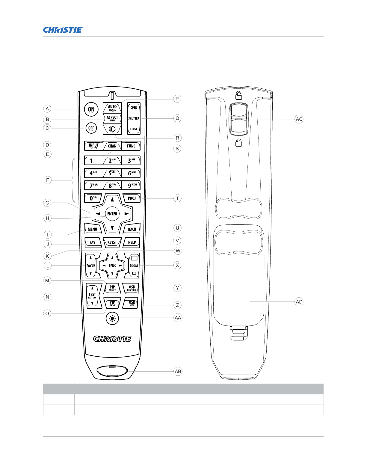
IR remote keypad
Introduction
The IR remote k
eypad controls the projector by way of wireless communications from a battery-
powered infrared (IR) transmitter.
Button Description
A Powers on the projector light source.
B Opens the aspect ratio dialog.
Mirage SST User Guide 18
020-102993-01 R
Copyright © 2019 Christie Digital Systems USA, Inc. All rights reserved.
ev. 1 (06-2019)
Page 19

Button Description
C Turns off the light source and puts the projector in standby.
D Selects an active or inactive input on any slot.
E Not supported.
F Enter a number, such as menu, item index or value.
G Use the arrows to navigate within a menu or to adjust settings.
H Selects a highlighted menu item and changes or accepts a value.
I Toggles the menus on/off.
J Not supported.
K Opens the keystone dialog.
L Adjusts the lens focus.
M Not supported.
N Displays a test pattern.
O Not supported.
P Optimizes the image automatically.
Introduction
Q Opens or closes the shutter.
R Not supported.
S Initiates a custom action when a number is selected.
T Selects a projector in multi-projector installations.
U Returns to the previous menu level or exits menus if at the top level.
V Displays context-sensitive help.
W Arrows adjust the lens offset.
X Adjust the lens zoom.
Y Opens the on-screen display position menu.
Z Shows or hides the on-screen display menus.
AA Turns the remote backlight on.
AB Male 3-pin XLR connector for wired option.
AC Lock/unlock the keypad.
AD Battery door.
Mirage SST User Guide 19
020-102993-01 R
Copyright © 2019 Christie Digital Systems USA, Inc. All rights reserved.
ev. 1 (06-2019)
Page 20

Operating the projector
Learn how to turn on and off the projector and the meaning of the status indicators.
Performing initial system start-up
Learn how to turn on all components of the
illumination source, and projector head.
Warning! If not a
• SHOCK HAZARD! Do not attempt operation if the AC supply is not within the specified voltage
and current, as specified on the license label.
Never run the laser illumination source without the cooling system already running. The chiller must
be the first item turned on before power is applied to the laser rack and kept operating until after the
AC lockout/switch is rotated to the off position.
1. Verify the coolant lines are connected correctly.
2. Fill the chiller reservoir with the required coolant (30% Propylene Glycol coolant).
3. Turn on the chiller, set the temperature to between 19°C (66°F) to 22°C (71.6°F).
For more information on how to turn on the chiller, refer to the chiller's product
documentation.
4. Check the coolant level in the reservoir and hoses and top up the coolant as required.
5. Check that no leaks exist in the system.
6. Allow the chiller to run until the system is operating with no new bubbles entering the
reservoir. Add additional coolant as necessary.
7. On the laser illumination source, rotate the main AC lockout/switch (A)to the on position and
rotate the Power key (B) clockwise to the on position.
The Interlock status indicator (C) on the laser illumination source turns yellow.
voided, the following could result in death or serious injury.
Mirage SST system for the first time: chiller, laser
Mirage SST User Guide 20
020-102993-01 R
Copyright © 2019 Christie Digital Systems USA, Inc. All rights reserved.
ev. 1 (06-2019)
Page 21

Operating the projector
8. On the projector beside the AC inlet, move the AC breaker/switch to the on position.
The projector boots into standb
y mode after approximately 30 seconds.
9. Once the projector is in standby, on the projector keypad or the projector remote, press and
hold the power button until you hear a beep.
The projector can also be turned on using the web user interface. After a few seconds, the
projector moves to the on state, causing the yellow light on the laser illumination source to
turn off. The laser is ready to be turned on but no illumination occurs until the green button is
pressed and the lasers have warmed up.
10. On the laser illumination source, press the green Start button (D).
The two Emission status indicators (E) turn red. When the lasers are warmed up and the
projector is ready, you can display an image (use test pattern if no source image is
connected).
On the projector, the Status > Laser Info > Laser Bank State menu displa
ys the message
"Warming Up". When that message disappears, the lasers are ready. It typically takes the
Mirage SST User Guide 21
020-102993-01 R
Copyright © 2019 Christie Digital Systems USA, Inc. All rights reserved.
ev. 1 (06-2019)
Page 22

Operating the projector
lasers approximately 10 to 15 minutes to warm up when turning on the first time from the off
position. This could be longer if the start
-up temperatures are approaching minimum or
maximum temperatures for operation. The projector will operate with the shutter closed until
the lasers are warmed up.
Turning on the system
After the system has been initiated for the first time, not all steps need to be performed when
subsequently turning on the system.
Warning! If not a
• SHOCK HAZARD! Do not attempt operation if the AC supply is not within the specified voltage
and current, as specified on the license label.
Never run the laser illumination source without the cooling system already running. The chiller must
be the first item turned on before power is applied to the laser r
AC lockout/switch is rotated to the off position.
1. Turn on the chiller.
For more information on how to turn on the chiller, refer to the chiller's product
documentation.
2. Check the coolant level. If the coolant level is low, add coolant and check for leaks.
3. On the laser illumination source, rotate the main AC lockout/switch (A) to the on position and
rotate the Power key (B) clockwise to the on position.
The Interlock status indicator (C) on the laser illumination source turns yellow.
voided, the following could result in death or serious injury.
ack and kept operating until after the
4. If the breaker is off, on the projector beside the AC inlet, move the AC breaker/switch to the
on position.
The projector boots into standb
Mirage SST User Guide 22
020-102993-01 R
Copyright © 2019 Christie Digital Systems USA, Inc. All rights reserved.
ev. 1 (06-2019)
y mode after approximately 30 seconds.
Page 23

Operating the projector
5. Once the projector is in standby, on the projector keypad or the projector remote, press and
hold the power button until you hear a beep.
The projector can also be turned on using the web user interface. After a few seconds, the
projector moves to the on state, causing the yellow light on the laser illumination source to
turn off. The laser is ready to be turned on but no illumination occurs until the green button is
pressed and the lasers have warmed up.
6. On the laser illumination source, press the green Start button (D).
The two Emission status indicators (E) turn red. When the lasers are warmed up and the
projector is ready, you can display an image (use test pattern if no source image is
connected).
On the projector, the Status > Laser Info > Laser Bank State menu displa
ys the message
"Warming Up". When that message disappears, the lasers are ready. It typically takes the
lasers approximately 10 to 15 minutes to warm up when turning on the first time from the off
position. This could be longer if the start-up temperatures are approaching minimum or
Mirage SST User Guide 23
020-102993-01 R
Copyright © 2019 Christie Digital Systems USA, Inc. All rights reserved.
ev. 1 (06-2019)
Page 24

Operating the projector
maximum temperatures for operation. The projector will operate with the shutter closed until
the lasers are w
armed up.
Turning off the system
Learn how to turn off all components of the Mirage SST system: projector head, laser and chiller.
When powering off in preparation for inspection or maintenance, always disconnect from AC.
1. To turn the light source off using the projector keypad or remote, press and hold the
ou hear a beep.
until y
button
The projector can also be turned off with the web user interface. Always allow the projector to
complete the 10 minute cool down cycle before power is turned off at the breaker or
unplugged or projector damage could occur.
2. On the laser illumination source, rotate the main AC lockout/switch (A) to the off position and
rotate the Power key (B) counter clockwise to the off position.
3. Christie recommends, if possible, to keep the chiller operating for 10 minutes after laser AC
lock
out/switch A has been rotated to the off position.
For more information on the chiller operation, refer to the chiller's product documentation.
Projector LED status indicators
Identify the LED state colors and meaning.
LED State Description
Blue Solid Standby Light source is off. Video electronics are off.
Projector status is OK.
Flashing Cool down Projector is moving to one of the two standby
states:
•
Light source is off and video electronics are
booting up.
Mirage SST User Guide 24
020-102993-01 R
Copyright © 2019 Christie Digital Systems USA, Inc. All rights reserved.
ev. 1 (06-2019)
Page 25

Operating the projector
LED State Description
• Light source is off. Video electronics and light
source is cooling down.
Green Solid Light source on Light source is on. Projector status is OK.
Flashing Startup Projector is moving to light source on state. Light
source is w
initializing.
arming up. Video electronics are
Yellow Solid Warning in
standby
Flashing yellow/green Warning during
startup
Flashing Warning with
light source on
Flashing yellow/blue Warning during
cool down
Red Solid Error in
standby
Flashing Error An error with the projector exists during startup,
Off AC off The AC power is off.
Projector is in standby state. A problem exists with
the projector that does not prevent it from
operating.
Projector is in a startup state. A problem exists
with the projector that does not prevent it from
operating.
Light source is on. A problem exists with the
projector that will not cause it to shut down.
Projector is in a cool down state. Light source is off.
Video electronics and light source are cooling
down. A problem exists with the projector that
does not prevent it from operating.
Projector is in standby. An error exists that
prevents the projector from starting up.
cool down, or when the light source is off. Projector
will proceed to shut down.
Projector LED shutter indicators
Identif
y the shutter LED state colors and meaning.
LED State Description
Solid magenta Shutter closed The shutter is closed.
In standb
the magenta light is muted.
Off Shutter open The shutter is open.
Mirage SST User Guide 25
020-102993-01 R
Copyright © 2019 Christie Digital Systems USA, Inc. All rights reserved.
ev. 1 (06-2019)
y, the shutter is always automatically closed and
Page 26

Adjusting the image
Adjust the projector image.
procedures as focus may change as the lens warms.
Christie recommends warming the lens before completing these
Selecting screen image orientation
Specify the orientation to use for the image. The projector supports front projection, rear projection,
front projection inverted, or rear projection inverted.
1. Select MENU > Image Settings > Image Orientation.
2. Select the required orientation from the list.
3. To confirm your selection, press Enter.
Setting the image resize preset
Set the image resize preset to determine if an image will display in its native resolution or will resize
by maximizing the height, width, both height and width, or to the maximum size while keeping the
original aspect ratio.
1. Select MENU > Image Settings > Size & Position > Resize Presets.
2. Select the appropriate resize preset:
• Auto—Maximize for current source.
• No Resizing—Display in native resolution.
• Full Size—Fill the screen, regardless of source.
• Full Width—Fill display width and keep aspect ratio.
• Full Height—Fill display height and keep aspect ratio.
3. Select Enter.
Adjusting lens settings
Adjust various lens settings including the offset, zoom, focus, and locking the lens motor.
Adjusting offset
Adjust the offset to align the image on the screen. Always adjust offset before adjusting boresight.
For the best optical performance and minimal keystone, use offsets instead of aiming at the center of
the image, in off
pattern indicate extreme offset that should be avoided using mechanical alignment.
1. Project an image with the primary lens.
Mirage SST User Guide 26
020-102993-01 R
Copyright © 2019 Christie Digital Systems USA, Inc. All rights reserved.
ev. 1 (06-2019)
-axis installations. Avoid extreme tilts or offsets. Corner vignettes on a white test
Page 27

Adjusting the image
2. Select a framing test pattern.
3.
Select LENS OFFSET.
4. Use the arrows to adjust the offset to display a square image on the screen, with minimal
projector aiming error.
5. To exit to the home page, select Back.
Resetting the lens to home position
Set the lens offset back to the home position.
1. Select LENS OFFSET.
You can also select MENU > Configuration > Lens Settings > Lens Offset.
2. To reset the lens to the default home position, select Enter.
3. To confirm the reset, select OK.
Aligning the image with lens zoom and focus
Ensure that the image reflected from the digital micromirror device (DMD) is parallel and centered
with the lens and screen.
1. Display an image or test pattern that can be used to analyze image focus and geometry.
2. Select ZOOM.
You can also select the zoom function from MENU > Configuration > Lens Settings >
Zoom.
3. Use the up and down arrows to zoom in or out of the image.
4. To exit, select Back.
5. Select FOCUS.
You can also select the focus function from MENU > Configuration > Lens Settings >
Focus.
6. Use the up and down arrows to adjust the focus of the image.
7. To exit, select Back.
8. To refine your adjusts, repeat steps 2 to 7.
Locking the lens motor
Prevents all lens motors from moving. It disables the zoom, focus, and offset settings, locking out any
changes and overriding all other lens features. This feature prevents accidental lens position changes
in multi-projector installations.
1. Select MENU > Configuration > Lens Settings > Lock all Lens Motors.
2. To enable locking of all lens motors, select Enter.
Determining what lens warnings are displayed
Controls the level of lens warnings displayed.
1. Select MENU > Configuration > Lens Settings > Lens Warnings.
2. Select the appropriate lens warning level:
Mirage SST User Guide 27
020-102993-01 R
Copyright © 2019 Christie Digital Systems USA, Inc. All rights reserved.
ev. 1 (06-2019)
Page 28

Adjusting the image
• Show All Warnings—
• Hide Zoom Motor Warnings—Hides zoom motor warnings.
• Hide Detection Warnings—Hides lens detection warnings. Christie recommends
selecting this option when using a third-party lens.
3. Select Enter.
Shows all lens warnings.
Adjusting primary colors
Calibrate the accuracy of primary colors, which can change because of lighting and environmental
factors.
All primary colors in the projector are precisely set to pre-established values to ensure overall color
performance is optimized and is as accurate as possible. Lighting and other environmental factors may
slightly change how these colors appear on your screen. While the change is negligible in most cases,
you may prefer to recover the originally intended color performance before trying to match colors from
several projectors.
To achieve consistency use a color meter to measure the native primary colors—red, green, blue, and
white—as they appear on the screen. On the basis of these new values, which are stored in memory,
each projector automatically calculates any necessary corrections to reproduce the original factory
colors under the current environmental conditions. This essentially calibrates a projector to its
surroundings, compensating for factors such as screen type, light source and/or ambient lighting, and
improves color accuracy and consistency in a group of projectors. It ensures a good starting point for
further customizing and matching; however, is not critical for all installations.
1. From the display panel, select MENU > Configuration.
2. Select Color Primary Settings.
3. To edit the primary colors, select Edit Primary Colors.
4. Adjust the slider or enter the measured color values of the primary color component you
selected.
5. To confirm your selection, select Enter.
6. Repeat steps 5 and 6 for each primary color component.
7. To view a specific color while adjusting, select Show Color Pattern.
8. Select the appropriate color and select Enter.
9. To reset the primary colors to their defaults, select Reset Color Primaries.
10. At the confirmation prompt, select OK.
DMD color correction
Adjust the DMD color values as required.
Adjusting color by precise chromaticity values
Change the values of the primary color components.
1. Select MENU > Configuration > Color Correction by x,y.
2. Adjust the slider or enter the measured color values of the primary color component you
selected.
Mirage SST User Guide 28
020-102993-01 R
Copyright © 2019 Christie Digital Systems USA, Inc. All rights reserved.
ev. 1 (06-2019)
Page 29

Adjusting the image
3. To confirm your selection, select Enter.
4.
Repeat steps 2 and 3 for each primary color component.
5. To view a specific color while adjusting, select Show Color Pattern.
6. Select the appropriate color and select Enter.
Adjusting color by saturation
Change the strength of the primary color in relation to the other primary colors.
1. Select MENU > Configuration > Color Saturation.
2. Adjust the value of the primary color you selected by using more or less of it in relation to the
other primary colors.
3. To confirm your selection, select Enter.
4. Repeat steps 2 and 3 for each primary color.
5. To view a specific color while adjusting, select Show Color Pattern.
6. Select the appropriate color and select Enter.
Signal color correction
Adjust the video signal color as required.
For best results, Christie recommends setting all color and gamma settings to Auto Detect.
Adjusting the color space
Determine how the color components are decoded for accur
1. Select MENU > Image Settings > Color & Gamma > Color Space.
2. Select the adjustment most suited to the input signal:
• Auto Detect
• RGB (Full Range)
• RGB (Limited Range)
• YCbCr HDTV (Expanded Range)
• YCbCr JPEG (Full Range)
• YCbCr UHDTV (ITU-R BT.2020) (Full Range)
3. Select Enter.
ate color in the display.
Adjusting color by temperature
Adjust the color temperature as expressed in degrees Kelvin.
1. Select MENU > Image Settings > Color & Gamma.
2. Select Color Temperature.
3. Adjust the slider to change the light to warmer or cooler and select Enter.
Mirage SST User Guide 29
020-102993-01 R
Copyright © 2019 Christie Digital Systems USA, Inc. All rights reserved.
ev. 1 (06-2019)
Page 30

Selecting the color correction mode
Select the color correction mode most suited to the input signal.
1.
Select MENU > Image Settings > Color & Gamma > Color Correction Mode.
2. Select the adjustment most suited to the input signal:
• Auto Detect—Automatically detect the appropriate color correction mode, where possible.
• Max Drives—All color adjustments are turned off, allowing the projector to run at
maximum brightness.
• Color Temperature—Specify a color temperature between 3200 and 9300, expressed in
degrees Kelvin.
• HD Video—Set the output color to a specific standard value. Adjusts the colors red,
green, blue, and white.
• DCI P3—Set the DCI P3 (cinema) colorimetry with DCI white point.
• DCI P3 (D65)—Set the DCI P3 colorimetry with D65 white point.
• Custom—Select a user defined set of color adjustments.
3. Select Enter.
Adjusting the image
Correcting for ambient light
Ambient light is the natural light that occurs in the environment where the projector is located.
1. Select MENU > Image Settings > Color & Gamma > Ambient Light Correction.
2. Select Enter.
3. Use the right and left arrows to adjust how the image displays in conditions with ambient light.
4. To confirm your selection, select Enter.
Setting the frame delay
Delay the output signal timing relative to the input signal timing by a fraction of a frame, and up to
several frames.
The minimum latency can vary based on the amount of scaling applied to the image. When using
keystone or warping, an additional latency is required, depending on the amount of warp.
1. Select MENU > Image Settings > Advanced Image Settings > Frame Delay.
2. To set the frame delay, select Set Delay.
3. Adjust the value and to confirm your selection, select Enter.
4. To set the achievable frame delay, select Actual Delay.
5. Adjust the value and to confirm your selection, select Enter.
Enabling film mode detect
Enables or disables the detection of film motion.
1. Select MENU > Image Settings > Advanced Image Settings > Film Mode Detect.
Mirage SST User Guide 30
020-102993-01 R
Copyright © 2019 Christie Digital Systems USA, Inc. All rights reserved.
ev. 1 (06-2019)
Page 31

Adjusting the image
2. To enable the detection of film motion, select Auto Detect.
3.
To disable the detection of film motion, select Disabled.
4. Select Enter.
Adjusting the image sharpness
Change the sharpness of the image.
Lower settings can improve a noisy signal. Setting the sharpness above the halfway point can
introduce noise in the image.
1. Select MENU > Image Settings > Advanced Image Settings > Sharpness.
2. Select Enter.
3. Use the right and left arrows to adjust the sharpness of the image.
4. To confirm your selection, select Enter.
Creating a seamless image with edge blending
Combine several projected images into one single, seamless image with edge blending.
Adding edge blends to the projector
Use Christie or to create edge blends and upload them to Mirage SST.
1. Create an edge blend file using the Christie or application.
To connect Mirage SST with Christie or , use port 3003.
Christie Twist Premium, Twist Pro, and offer advanced warping options. Refer to the Christie
website (www.christiedigital.com) for product information and documentation.
2. Upload the edge blend file to the projector.
3. On one projector, select MENU > Configuration > Edge Blending.
4. Select the appropriate edge blend setting and select Enter.
5. Repeat steps 2 to 4 for the remaining projectors.
6. To turn off edge blending, from MENU > Configuration > Edge Blending, select Off.
Enabling basic edge blending
Create basic edge blends directly on Mirage SST.
1. Start with two projectors and display the full white field test pattern from both.
2. On one projector, select MENU > Configuration > Edge Blending.
3. To enable basic edge blending, select Basic.
4. To edit blending adjustments, select Edge Blend Widths.
5. From the Basic Blending dialog, select a side to blend.
6. To make the blending adjustments, use the arrow keys to change either the vertical and
horizontal values as appropriate.
Mirage SST User Guide 31
020-102993-01 R
Copyright © 2019 Christie Digital Systems USA, Inc. All rights reserved.
ev. 1 (06-2019)
Page 32

Adjusting the image
7. To accept the selection, select Enter.
8.
Repeat steps 4 to 6 to blend the remaining sides.
9. When all adjustments are made, use the arrow keys to highlight Apply and select Enter.
10. Repeat steps 2 to 9 for the remaining projectors.
11. To turn off basic edge blending, from MENU > Configuration > Edge Blending, select Off.
Resetting edge blending
Reset the edge blending to revert any edge blends.
1. Select MENU > Configuration > Edge Blending.
2. Select Reset Edge Blends.
3. At the confirmation prompt, select Reset.
Geometry correction
Modify the geometry for all sources.
Enabling warping
Use warping to project images on any surface shape.
1. Create a warp file using the Mirage SST or application.
To connect Mirage SST with or , use port 3003.
Christie Twist Premium, Twist Pro, and offer advanced warping options. Refer to the Christie
website (www.christiedigital.com) for product information and documentation.
2. Upload the warp file to the projector.
3. Select MENU > Configuration > Geometry Correction > Geometry Correction Mode.
4. Select the appropriate warp setting and select Enter.
5. To turn off warping, from MENU > Configuration > Geometry Correction > Geometry
Correction Mode, select Off.
Pressing Func+Help on the IR remote keypad disables all geometry corrections (warping,
keystone, and black level blending) without changing the settings associated with them.
Correcting the shape of a keystoned image
Keystone effect occurs when you project an image onto the screen at an angle and the projector is not
centered on the screen. The image appears distorted and resembles a trapezoid.
To correct the shape of a keystoned image, use the keystone options available in the geometry
correction menu. Perform coarse keystone adjustments by using the horizontal or vertical settings. It
may not be possible to match the screen dimensions with the horizontal and vertical keystone controls
but you can refine these settings by adjusting the 2D keystone settings.
Enabling keystone adjustments
Enable keystone corrections to correct the shape of a keystoned image.
1. Select MENU > Configuration > Geometry Correction > Geometry Correction Mode.
Mirage SST User Guide 32
020-102993-01 R
Copyright © 2019 Christie Digital Systems USA, Inc. All rights reserved.
ev. 1 (06-2019)
Page 33

Adjusting the image
2. Select Keystone.
An
y keystone adjustments previously set are enabled.
To disable keystone adjustments, select MENU > Configuration > Geometry Correction >
Geometry Correction Mode > Off.
Adjusting the image with 2D keystone
2D keystone distorts the projected image both vertically and horizontally simultaneously and
resembles a trapezoid.
Adjusting horizontal or vertical keystone correction after 2D keystone erases the 2D keystone settings;
however, performing 2D keystone after horizontal or vertical correction retains the previous keystone
setting.
1. Select MENU > Configuration > Geometry Correction > Geometry correction Mode.
Select 2D Keystone Correction.
2.
3. From the correction dialog, select the corner to adjust.
4. To make the keystone adjustments, use the arrow keys to change both the vertical and
horizontal values.
5. Select Apply Changes.
Adjusting vertical keystone
Use vertical keystone to correct a keystoned image shape in which the top and bottom borders of the
image are unequal in length, and both sides of the image are inclined toward the top or bottom edge.
If vertical keystone adjustments have been made, starting horizontal keystone adjustments erases the
vertical settings.
1. Select MENU > Configuration > Geometry Correction > Geometry Correction Mode.
Select Vertical Keystone Correction.
2.
3. From the correction dialog, adjust the vertical keystone by using the arrow keys.
4. Select Apply Changes.
Adjusting horizontal keystone
Use horizontal keystone to correct a keystoned image shape in which the left and right borders of the
image are unequal in length, and the top and bottom are slanted to one of the sides.
If horizontal keystone adjustments have been made, starting vertical keystone adjustments erases the
horizontal settings.
Mirage SST User Guide 33
020-102993-01 R
Copyright © 2019 Christie Digital Systems USA, Inc. All rights reserved.
ev. 1 (06-2019)
Page 34

Adjusting the image
1. Select MENU > Configuration > Geometry Correction > Geometry Correction Mode.
Select Horizontal Keystone Correction.
2.
3. From the correction dialog, adjust the horizontal keystone by using the arrow keys.
4. Select Apply Changes.
Resetting keystone correction
Reset keystone to revert the distorted image shape back to default values.
Pressing Func+Help on the IR remote keypad disables all geometry corrections (warping, keystone,
and black level blending) without changing the settings associated with them.
1. Select MENU > Configuration > Geometry Correction.
2. Select Reset Keystone Correction.
3. At the confirmation prompt, select Reset.
Mirage SST User Guide 34
020-102993-01 R
Copyright © 2019 Christie Digital Systems USA, Inc. All rights reserved.
ev. 1 (06-2019)
Page 35

Configuring system settings
Learn how to configure the system settings.
Setting the date
Configure the date on
1. Select Menu > System Settings.
2. Select Date.
3. Use the up and down keys to adjust the year (YYYY), month (MM), and day (DD).
Mirage SST.
Setting the time
Configure the time on Mirage SST.
1. Select Menu > System Settings.
2. Select Time.
3. Use the up and down keys to adjust the hour (HH), minutes (MM), and seconds (SS).
Changing the splash screen
Select the color displayed on the screen.
1. Select MENU > System Settings > Splash Screen Settings > Background Color.
2. Select a splash screen background color:
• Black
• Red
• Green
• Blue
3. Select Enter.
Determining the on-screen display position
Choose one of the pre-defined locations for the display of the on-screen menus.
1. Select MENU > System Settings > Menu Preferences > OSD Position.
Mirage SST User Guide 35
020-102993-01 R
Copyright © 2019 Christie Digital Systems USA, Inc. All rights reserved.
ev. 1 (06-2019)
Page 36

Configuring system settings
2. Select the location on the screen where you want the on-screen display menus to appear.
3.
Select Enter.
Changing the language
Choose the language you want displayed on projector display panel and on-screen display.
1. Select MENU > Languages.
You can also select the language from MENU > System Settings > Menu Preferences >
Languages.
2. Select Enter.
3. Select the appropriate language and select Enter.
The change takes effect immediately.
Changing the temperature units
Set if the temperature is measured in Celsius or Fahrenheit.
1. Select MENU > System Settings > Menu Preferences > Temperature Units.
2. Select the temperature unit: Celsius or Fahrenheit.
3. Select Enter.
Resuming projector operation after an AC power interruption
If an AC power interruption occurs while Auto Power Up is enabled, the projector will resume operation
in the same state it was prior to the loss of power.
1. Select MENU > System Settings > Power Settings.
2. Select Auto Power Up.
3. To enable automatically powering up the projector after an AC interruption, select Enter.
Keeping electronics on in standby mode
When the projector is placed in standby mode, the light source will be turned off but the electronics
will remain on.
1. Select MENU > System Settings > Power Settings.
2. Select Keep Electronics On In Standby.
3. To enable electronics remaining on in standby mode, select Enter.
Mirage SST User Guide 36
020-102993-01 R
Copyright © 2019 Christie Digital Systems USA, Inc. All rights reserved.
ev. 1 (06-2019)
Page 37

Configuring system settings
Enabling direct pass-through of HDMI, 3G, and DisplayPort input signals
Allow the signals from HDMI, 3G, and Displa
1. Select MENU > Configuration > Input Settings > Enable Video Loop Out.
2. To enable passing HDMI, 3G, and DisplayPort input signals through to another projector, select
Enter.
yPort inputs to pass through another projector.
Informing the source of signal preferences
Configure Mirage SST to automatically inform the video source of the preferred signal formats.
1. If you need a specific frame rate, from the display panel, select MENU > Configuration >
Input Settings > EDID Timing.
2. Select the required EDID timing and select Enter.
60 Hz is the default EDID timing.
Configuring the laser power settings
Projector profiles contain the power settings for the RGB laser light source.
1. To display the white test pattern, MENU > Test Pattern
2. Scroll through the list of test patterns and select White.
3. To confirm your selection, select Enter.
4. Select MENU > Image Settings > Color & Gamma > Color Correction Mode.
5. Select Max Drives and to confirm your selection, select Enter.
6. Select MENU > Configuration > Light & Output Settings.
7. To set the approximate red power level, select Red Laser Setpoint and use the slider to
increase and decrease the value required for your projection environment.
To turn off the red lasers but leave them in a ready state, select Red Laser Enable to clear
the checkbox.
8. To set the green (Green Laser Setpoint) and blue (Blue Laser Setpoint) power levels,
repeat step 7.
To turn off either the green or blue lasers but leave them in a ready state, select Green Laser
Enable or Blue Laser Enable to clear the checkbox.
9. If color is not at the target level, refine the red, green, and blue power settings to achieve the
target by repeating steps 7 and 8.
10. To control the brightness once the colors are set, select Maser Laser Power and use the
slider to increase or decrease the value.
To turn off all lasers but leave them in a ready state, select Maser Laser Enable to clear the
checkbox.
11. To save the new laser settings, save to a projector profile.
Mirage SST User Guide 37
020-102993-01 R
Copyright © 2019 Christie Digital Systems USA, Inc. All rights reserved.
ev. 1 (06-2019)
Page 38

Setting up 1D color uniformity
Configuring system settings
Learn how to set up 1D color uniformit
y on the projector after taking measurement of each of the
color primaries at points (15, 2, 5, 8, and 16).
1. Ensure the projector is running in representative ambient light.
2. Setup a spectroradiometer, such as the CR-250, on a tripod.
If not using the CR-250 or better, Christie recommends placing the meter perpendicular to the
screen to achieve accurate measurements.
Do not use the PR-655 spectroradiometer to perform color uniformity on a multi-projector
installation.
3. Power on the projector.
4. Allow the light source to stabilize.
5. Select MENU > Configuration > Horizontal 1D Color Uniformity.
6. To disable color uniformity, select Color Uniformity Mode.
7. Select Enter.
8. Select MENU > Image Settings > Color & Gamma > Color Correction Mode.
9. Select Max Drives and to confirm your selection, select Enter.
10. Select Show Color Pattern > Auto and to confirm your selection, select Enter.
11. From the side panel home page, use the arrows to select Test Pattern.
12. Select the 17 Point test pattern and to confirm your selection, select Enter.
13. Record the x, y, and RGB luminance values for the center point.
Point the spectroradiometer at point 5 (middle square).
a)
b) Click the X value.
c) Record the x value from the spectroradiometer.
d) Click the Y value.
e) Record the y value from the spectroradiometer.
f) Click on the Red luminance setting.
The display changes to the appropriate color.
g) Record the luminance value from the spectroradiometer.
h) Click on the Green luminance setting.
The display changes to the appropriate color.
i) Record the luminance value from the spectroradiometer.
j) Click on the Blue luminance setting.
Mirage SST User Guide 38
020-102993-01 R
Copyright © 2019 Christie Digital Systems USA, Inc. All rights reserved.
ev. 1 (06-2019)
Page 39

Configuring system settings
The display changes to the appropriate color.
k)
Record the luminance value from the spectroradiometer.
14. Record the luminance values for the remaining four points (2—inside left, middle square; 15—
far left, middle square; 8—inside right, middle square; and 16—far right, middle square)
a) Point the spectroradiometer at a point.
b) Click on the Red luminance setting.
The display changes to the appropriate color.
c) Record the luminance value from the spectroradiometer.
d) Click on the Green luminance setting.
The display changes to the appropriate color.
e) Record the luminance value from the spectroradiometer.
f) Click on the Blue luminance setting.
The display changes to the appropriate color.
g) Record the luminance value from the spectroradiometer.
h) For the remaining three points, repeat steps a to g.
15. Select MENU > Configuration > Horizontal 1D Color Uniformity.
16. To enable color uniformity, select Color Uniformity Mode.
17. Select Enter.
18. To verify 1D color uniformity is working, enable a flat white test pattern.
Turning on the projector with low voltage
Enable the projector to turn on even if the AC mains voltage is below specification.
1. From the display panel, select MENU > Admin > Service.
2. Enter the service password.
3. Select Ignore Low AC Input Voltage Error.
4. To ignore the Low AC Input Voltage error when turning on the projector, select Enter.
Mirage SST User Guide 39
020-102993-01 R
Copyright © 2019 Christie Digital Systems USA, Inc. All rights reserved.
ev. 1 (06-2019)
Page 40

Configuring communications
Defines and controls how single or multiple projectors are link
device.
ed with each other and with a controlling
Enabling projector communication
Enable the receivers and the wired keypad to communicate with the projector from the remote.
The front and rear IR sensors receive transmissions from the IR remote. Keep the transmission path to
these sensors unobstructed for uninterrupted communications with the projector.
Alternatively, you can connect a wired version of the remote to the connector on the IMXB labeled
Wired Keypad.
1. Select MENU > Communications > Projector Communications.
2. To assign the projector an ID, select Projector ID.
3. Use the up and down keys to enter the projector ID.
4. Select Enter.
5. To enable the rear IR sensor, select Rear IR Enabled and select Enter.
6. To enable a wired version of the remote, select Wired Keypad Enabled and select Enter.
By default this feature is enabled.
Setting the remote access level
Determine if and how the projector can be accessed remotely for the RS232 port or the Ethernet.
1. From the display panel, select MENU > Admin > Service.
2. Enter the service password.
3. To determine the remote access for the Ethernet port, select Remote Access Level
(Ethernet).
4. Select the appropriate remote access level:
• No Access
• Login Required
• Free Access
5. Select Enter.
6. To determine the remote access for the RS232 IN port, select Remote Access Level (RS232
IN).
7. Select the appropriate remote access level:
Mirage SST User Guide 40
020-102993-01 R
Copyright © 2019 Christie Digital Systems USA, Inc. All rights reserved.
ev. 1 (06-2019)
Page 41

Configuring communications
• No Access
•
Login Required
• Free Access
8. Select Enter.
Communicating with Mirage SST through Art-Net
Mirage SST supports communications through the Art-NET using the Ethernet connector.
1. Select MENU > Communications > Art-Net Settings.
2. Verify the Enable Art-Net option is disabled.
Disabling Art-Net before configuring it ensures Mirage SST does not accidentally respond to
DMX messages destined for other devices on the network.
3. To specify which subnet the projector belongs to, in the Art-Net Subnet field adjust the value
between 0 and 15.
The subnet provides expandability beyond the universe level.
4. To confirm your selection, select Enter.
5. To specify which universe the projector belongs to, so it can filter out all other data packets, in
the Art-Net Universe field, adjust the value between 0 and 15.
For Art-Net, data is broadcast over an Ethernet network, so every device receives every packet
of data, whether the device belongs to that universe or not.
6. To confirm your selection, select Enter.
7. To determine the starting channel for this projector, in the Base Channel field, adjust the value
between 1 and 488.
If multiple projectors are used on the same universe and are to be controlled independently,
this value must be changed. For example, if both projectors are using the Shutter (20
channels), projector 1 should start at base channel 1 and projector 2 should start at base
channel 21.
8. To confirm your selection, select Enter.
9. Select Enable Art-Net.
10. To enable the Art-Net functionality, select Enter.
Art-Net channel listing
There are 512 channels per universe. Mirage SST specifies 24 channels.
Mirage SST has multiple methods of being controlled in addition to Art-Net. If a setting is changed
through another interface, the DMX controller can reappropriate DMX channel.
Channel Name Description Suggested
1 Slider Lock 0 to 171 = Locked
172 to 255 = Unlock
Mirage SST User Guide 41
020-102993-01 R
Copyright © 2019 Christie Digital Systems USA, Inc. All rights reserved.
ev. 1 (06-2019)
assert control by changing the value on the
Notes
starting
position
0 —
ed
Page 42

Configuring communications
Channel Name Description Suggested
starting
position
2 Power 0 to 85 = Powers off the
projector (goes into
Standb
y mode)
86 to 171 = Cancel timer
172 to 255 = Powers on
the projector (switches
light source on, warm up
mode)
3 Shutter 0 to 85 = Closes the
shutter (black screen)
172 to 255 = Opens the
shutter (live video)
4 Lens Shift Enable 0 to 171 = Disables lens
shift
172 to 255 = Enables lens
shift
5 Zoom (Coarse) 0 = Smallest image
6 Zoom (Fine)
possible (0%)
255 = Largest image
possible (100%)
128 Must be valid for five seconds
255 Christie recommends setting
— Locks all lens motors.
128
Notes
before it is applied.
this channel to 255 prior to
powering up the projector so
it is consistent with the
shutter state after the
projector is fully on.
• Locked by the Lens Shift
Enable channel.
• Scaled as a percentage of
the total control range.
• A 250 ms delay exists
before sending this
channel to the projector.
7 Focus (Coarse) 0 = 0%
8 Focus (Fine)
255 = 100%
128
• Locked by the Lens Shift
Enable channel.
• Scaled as a percentage of
the total control range.
• A 250 ms delay exists
before sending this
channel to the projector.
9 Lens Horizontal
Position (Coarse)
10 Lens Horizontal
Position (Fine)
0 = Full left position (0%)
255 = Full right position
(100%)
128
• Locked by the Lens Shift
Enable channel.
• A 250 ms delay exists
before sending this
channel to the projector.
11 Lens Vertical Position
(Coarse)
12 Lens Vertical Position
(Fine)
0 = Full lower position
(0%)
255 = Full upper position
(100%)
128
• Locked by the Lens Shift
Enable channel.
• A 250 ms delay exists
before sending this
channel to the projector.
Mirage SST User Guide 42
020-102993-01 R
Copyright © 2019 Christie Digital Systems USA, Inc. All rights reserved.
ev. 1 (06-2019)
Page 43

Configuring communications
Channel Name Description Suggested
starting
position
13 Input 1 to 80 = Input index
86 = Load
91 to 170 = Additional
input indices
171 = Ex
14 Fade Time 0 = 0 seconds
250 = 2.5 seconds
15 to 24 Reserved Reserved for future use. — —
ecute
0 To change inputs, send the
— Determines the length of time
Index list for the input channel
the following table pro
Not all options listed in the table are available on all products. Available options depend on the projector
model and the cards installed on the projector
option to be set.
vides the index information for the input channel.
. The QSFP+ options require the Enable Christie Link
Notes
following sequence:
Load > Input index > Execute
For a list of input indices, see
Index list for the input channel
(on page 43).
Channel 1 slider lock can be
used if a keypad is not
available for the input
selection.
it takes for the shutter to open
and close with a fading effect.
Input
index
1 One-port [0-1] 44 Four-Port [1-2][2-2][3-2][4-2]
2 One-port [0-2] 45 One-Port, Dual-Input 3D L:[0-1],R:[0-2]
3 One-port [0-3] 46 One-Port, Dual-Input 3D L:[0-3],R:[0-4]
4 One-port [0-4] 47 One-Port, Dual-Input 3D L:[1-1],R:[1-2]
5 One-Port [1-1] 48 One-Port, Dual-Input 3D L:[1-3],R:[1-4]
6 One-Port [1-2] 49 One-Port, Dual-Input 3D L:[2-1],R:[2-2]
7 One-Port [1-3] 50 One-Port, Dual-Input 3D L:[2-3],R:[2-4]
8 One-Port [1-4] 51 One-Port, Dual-Input 3D L:[3-1],R:[3-2]
9 One-Port [2-1] 52 One-Port, Dual-Input 3D L:[3-3],R:[3-4]
10 One-Port [2-2] 53 One-Port, Dual-Input 3D L:[4-1],R:[4-2]
11 One-Port [2-3] 54 One-Port, Dual-Input 3D L:[4-3],R:[4-4]
12 One-Port [2-4] 55 One-Port, Dual-Input 3D L:[1-1],R:[2-1]
13 One-Port [3-1] 56 One-Port, Dual-Input 3D L:[1-2],R:[2-2]
14 One-Port [3-2] 57 One-Port, Dual-Input 3D L:[1-3],R:[2-3]
15 One-Port [3-3] 58 One-Port, Dual-Input 3D L:[1-4],R:[2-4]
Description Input
index
Description
Mirage SST User Guide 43
020-102993-01 R
Copyright © 2019 Christie Digital Systems USA, Inc. All rights reserved.
ev. 1 (06-2019)
Page 44

Configuring communications
Input
index
Description Input
index
Description
16 One-Port [3-4] 59 One-Port, Dual-Input 3D L:[3-1],R:[4-1]
17 One-Port [4-1] 60 Two-Port, Dual-Input 3D L:[0-1][0-2],R:[0-3][0-4]
18 One-Port [4-2] 61 Two-Port, Dual-Input 3D L:[1-1][1-2],R:[1-3][1-4]
19 One-Port [4-3] 62 Two-Port, Dual-Input 3D L:[2-1][2-2],R:[2-3][2-4]
20 One-Port [4-4] 63 Two-Port, Dual-Input 3D L:[3-1][3-2],R:[3-3][3-4]
22 Two-Port [0-1][0-2] 65 Two-Port, Dual-Input 3D L:[1-1][1-2],R:[2-1][2-2]
23 Two-Port [0-3][0-4] 66 Two-Port, Dual-Input 3D L:[3-1][3-2],R:[4-1][4-2]
24 Two-Port [1-1][1-2] 67 Two-Port, Dual-Input 3D L:[1-1][2-1],R:[3-1][4-1]
25 Two-Port [1-3][1-4] 68 Four-Port, Dual-Input 3D L:[1-1][1-2][2-1][2-2],R:
[3-1][3-2][4-1][4-2]
26 Two-Port [2-1][2-2] 69 Four-Port, Dual-Input 3D L:[1-1][1-2][1-3][1-4],R:
[2-1][2-2][2-3][2-4]
27 Two-Port [2-3][2-4] 70 Four-Port (columns) [0-1][0-2][0-3][0-4]
28 Two-Port [3-1][3-2] 71 Four-Port (columns) [1-1][1-2][1-3][1-4]
29 Two-Port [3-3][3-4] 72 Four-Port (columns) [2-1][2-2][2-3][2-4]
30 Two-Port [4-1][4-2] 73 Four-Port (columns) [3-1][3-2][3-3][3-4]
31 Two-Port [4-3][4-4] 74 Four-Port (columns) [4-1][4-2][4-3][4-4]
32 Two-Port [1-1][2-1] 75 Four-Port (columns) [1-1][1-2][2-1][2-2]
33 Two-Port [3-1][4-1] 76 Four-Port (columns) [3-1][3-2][4-1][4-2]
34 Two-Port [1-2][2-2] 77 Four-Port (columns) [1-1][2-1][3-1][4-1]
35 Two-Port [3-2][4-2] 78 Four-Port (columns) [1-2][2-2][3-2][4-2]
36 Four-Port [0-1][0-2][0-3][0-4] 79 Four-Port (columns), Dual-Input 3D L:[1-1][1-2]
[2-1][2-2],R:[3-1][3-2][4-1][4-2]
37 Four-Port [1-1][1-2][1-3][1-4] 80 Four-Port (columns), Dual-Input 3D L:[1-1][1-2]
[1-3][1-4],R:[2-1][2-2][2-3][2-4]
38 Four-Port [2-1][2-2][2-3][2-4] 91 QSFP+ [0-1]
39 Four-Port [3-1][3-2][3-3][3-4] 92 QSFP+ [0-2]
40 Four-Port [4-1][4-2][4-3][4-4] 93 QSFP+ [1-1]
41 Four-Port [1-1][1-2][2-1][2-2] 94 QSFP+ [1-2]
42 Four-Port [3-1][3-2][4-1][4-2] 95 QSFP+ [2-1]
43 Four-Port [1-1][2-1][3-1][4-1] 96 QSFP+ [2-2]
Mirage SST User Guide 44
020-102993-01 R
Copyright © 2019 Christie Digital Systems USA, Inc. All rights reserved.
ev. 1 (06-2019)
Page 45

Configuring communications
Working with macros
utomate tasks in Mirage SST with macros so the same tasks can be done on a regular basis.
A
If the date and/or time is changed on the projector, a macro may be unexpectedly executed.
Adding a macro
Create a macro to automate a repetitiv
Up to 10 macros can be created.
This feature is only available on the web interface.
1. From the home page of the web interface, select MENU > Macros and GPIO.
2.
Click the Add Macro.
If the limit of 10 macros is reached, the Add Macro button is disabled and displays a Limit
Reached message.
3. In the Name field, enter a meaningful name for the macro.
4. Verify that Scheduled Event is listed in the Type list.
5. In the Start Date field, select a date from the calendar.
6. In the Start Time field, use the up and down keys to adjust the hour (HH), minutes (MM), and
seconds (SS).
You can also manually enter the hour, minutes, and seconds.
7. To make this a reoccurring event, click Recurring.
When enabled, the button appears green. When disabled, the button appears gray.
a) To determine the recurrence pattern, under Every, select the day or days of the week you
want run the macro.
b) Determine the life of the macro.
• To have the macro run indefinitely, select No end date.
• To run the macro for a defined period of time, in the Recur for field, use the up and
down keys to adjust the number of weeks.
You can also manually enter the number of weeks. The limit is 99 weeks.
8. In the Serial Command field, enter the serial command(s) you want to run.
For available serial commands and their syntax, refer to the Mirage SST Serial Commands
Guide (P/N: 020-103005-XX).
9. To test the functionality, click Test.
An Action succeeded message is displayed upon a successful test.
10. To save the macro, click Save.
e task.
Copying a macro
Duplicate a macro to create another macro of similar functionality.
Up to 10 macros can be created.
Mirage SST User Guide 45
020-102993-01 R
Copyright © 2019 Christie Digital Systems USA, Inc. All rights reserved.
ev. 1 (06-2019)
Page 46

Configuring communications
This feature is only available on the web interface.
1. From the home page of the web interface, select MENU > Macros and GPIO.
2.
From the list of macros, click Duplicate next to the macro you want to copy.
If the limit of 10 macros is reached, the Duplicate
button is disabled and the Add Macros
button displays a Limit Reached message.
3. In the Name field, enter a meaningful name for the macro.
4. Modify the appropriate fields.
5. To save the macro, click Save.
Editing a macro
Edit the macro if the functionality of the macro has changed.
This feature is only available on the web interface.
1. From the home page of the web interface, select MENU > Macros and GPIO.
2.
From the list of macros, click Edit next to the macro you want to edit.
3. Modify the appropriate fields.
4.
To save the macro, click Save.
Deleting a macro
Delete one or more macros if they are no longer relevant.
This feature is only available on the web interface.
1. From the home page of the web interface, select MENU > Macros and GPIO.
2.
From the list of macros, select one or more macros to delete.
To delete all the macros in the list, click Select All. the number of macros you want to delete
is displayed next to the trash can.
3. Click Delete.
4. At the confirmation prompt, click Delete.
Mirage SST User Guide 46
020-102993-01 R
Copyright © 2019 Christie Digital Systems USA, Inc. All rights reserved.
ev. 1 (06-2019)
Page 47

Configuring the GPIO
Configuring communications
The Generic Purpose Input Output (GPIO) pro
vides a flexible method of interfacing with external
devices to the projector.
The GPIO is configured to automate real time events. Each of the seven pins is defined as either an
input or output depending on the required outcome. The remaining two pins are reserved for ground
and power.
Configure the pin as an input if you want the projector to respond to something the device does and
as an output if you want the external device to respond to an action taken by the projector. For
example, configure the pin as an output if you want the lighting in a room to automatically dim when
the projector is turned on.
This feature is only available on the web interface.
1. From the home page of the web interface, select MENU > Macros and GPIO.
2.
Select GPIO Configuration.
3. In the GPIO Configuration dialog under Update the New Configuration, toggle the pins you
want active for the input and output.
A blue pin indicates input and a green pin indicates output.
4. Select Apply.
GPIO connector
The GPIO connector located on the input panel provides a flexible method of interfacing with the
projector. Seven GPIO pins are available on the nine pin D-Sub GPIO connector. Two other pins are
reserved for ground and power.
D-SUB pin number Signal Output high (Voh) Notes
Pin 1 +12V — 1A max
Pin 2 GPIO 2 5V 75mA max
Pin 3 GPIO 4
Pin 4 GPIO 6
Pin 5 Ground — —
Mirage SST User Guide 47
020-102993-01 R
Copyright © 2019 Christie Digital Systems USA, Inc. All rights reserved.
ev. 1 (06-2019)
(e)fused to prev
damage
ent
Page 48

Configuring communications
D-SUB pin number Signal Output high (Voh) Notes
Pin 6 GPIO 1 5V 75mA max
Pin 7 GPIO 3
Pin 8 GPIO 5
Pin 9 GPIO 7
All GPIO pins are weakly pulled up to 3.3V.
(e)fused to prev
damage
ent
Mirage SST User Guide 48
020-102993-01 R
Copyright © 2019 Christie Digital Systems USA, Inc. All rights reserved.
ev. 1 (06-2019)
Page 49

Setting up projector profiles
Use the projector profiles to store configured settings so y
required.
ou can switch between the profiles as
Creating a new projector profile
Save the projector configuration to a profile so you can revert to those saved settings any time. You
can save up to 10 projector profiles.
1. Configure the projector settings you want to save to the profile.
2. Select MENU > Admin > Projector Profiles.
3. Select an empty profile.
4. Select New Profile.
5. Select Save.
Importing a projector profile
Import projector profiles set on different projectors using a USB flash drive.
1. Insert the USB flash drive containing the projector profile file into the USB port on the
projector.
2. Select MENU > Admin > Projector Profiles.
3. Select an empty profile.
4. Select Import From File.
5. From the File Selection dialog, select a projector profile file.
The projector profile file is imported to the projector.
Restoring settings from a profile
Return the projector to the configuration specified in a specific projector profile.
1. Select MENU > Admin > Projector Profiles.
2. Select an existing profile.
3. Select Restore Profile.
4. From the Restore dialog, select the settings you want to restore.
5. Select Restore.
Mirage SST User Guide 49
020-102993-01 R
Copyright © 2019 Christie Digital Systems USA, Inc. All rights reserved.
ev. 1 (06-2019)
Page 50

Renaming a projector profile
Setting up projector profiles
A newly created projector profile is giv
saved, for example, . You can change the name of the saved profile to a more meaningful name.
1. Select MENU > Admin > Projector Profiles.
2. Select an existing profile.
3. Select Rename Profile.
4. Use the up and down keys to enter the new name of the profile.
5. Select Save.
en the name of the projector with the date the profile was
Exporting a projector profile to an external device
Save the projector settings to a USB flash drive.
1. Insert a USB flash drive (properly formatted as FAT) into the USB port on the projector.
2. Select MENU > Admin > Projector Profiles.
3. Selecting an existing profile.
4. Select Export to File.
A default name is assigned.
Deleting a projector profile
If the settings in the projector profile are no longer relevant, delete the profile.
1. Select MENU > Admin > Projector Profiles.
2. Select the profile you want to delete.
3. Select Delete Profile.
4. At the confirmation prompt, select Delete.
Mirage SST User Guide 50
020-102993-01 R
Copyright © 2019 Christie Digital Systems USA, Inc. All rights reserved.
ev. 1 (06-2019)
Page 51

Backing up, restoring, and upgrading files
Learn how to back up
, restore, and upgrade files.
Upgrading the Mirage SST software
When a new version of the software is released, Mirage SST must be upgraded.
1. Turn off the lasers before proceeding with the upgrade.
2. Insert a USB key that contains the software upgrade file.
The USB flash drive must be formatted using the FAT 32 file system.
The upgrade file must be located at the root of the USB key.
3. From the display panel, select MENU > Admin.
4. Select Software > Upgrade.
5. Select an upgrade file and select Enter.
6. To automatically restart Mirage SST, select Restart Now.
If you decide restart Mirage SST at a later date (Restart Later), you cannot perform another
upgrade until the Mirage SST is restarted.
Exporting backup settings to an external device
Save the Mirage SST settings to a USB flash drive (projector) or file (web interface).
1. If using the display panel to export settings, insert a USB flash drive (properly formatted as
FAT) into the USB port on Mirage SST.
2. Select MENU > Admin > Backup & Restore.
3. Select the backup option.
• On the projector, select Backup to USB.
• On the web interface, select Backup to File.
A default name is assigned.
4. To edit the backup file name, select the up arrow and select Enter.
5. To save the name, navigate down and select SAVE.
The backup file is exported.
Mirage SST User Guide 51
020-102993-01 R
Copyright © 2019 Christie Digital Systems USA, Inc. All rights reserved.
ev. 1 (06-2019)
Page 52

Backing up, restoring, and upgrading files
Importing a file from an external device to restore settings
estore backed up files, stored on a USB flash drive (projector) or file (web interface), onto the
R
projector.
1. If using the display panel to import the file, insert the USB flash drive containing the backup
file into the USB port on the projector.
2. Select MENU > Admin > Backup & Restore.
3. Select the restore option.
• On the projector, select Restore from USB.
• On the web interface, select Restore from File.
4. From the File Selection dialog, select a file to restore.
The backup settings file is imported to the projector.
Restoring projector default settings
Restore the Mirage SST settings back to the default values. Network configurations and calibration
values are not reset.
1. From the display panel, select MENU > Admin > Backup & Restore.
2. Select .
All customized settings are set to the default Mirage SST settings.
Mirage SST User Guide 52
020-102993-01 R
Copyright © 2019 Christie Digital Systems USA, Inc. All rights reserved.
ev. 1 (06-2019)
Page 53

Diagnostic tools
F
ollow these procedures to help with diagnosing issues with Mirage SST.
Viewing Mirage SST information
View the licenses for the software added to Mirage SST and the licenses of the software used to
operate Mirage SST. The information is read-only.
1. To view the additional software added to Mirage SST, select MENU > Admin > Licenses.
2. To view the software licenses used to run Mirage SST, select MENU > Admin > About.
Freezing an image
Use the Freeze Image diagnostic tool to examine in detail a still version of an incoming image.
For example, in moving images sometimes it is difficult to observe artifacts such as external deinterlacing/resizing and signal noise.
1. Select MENU > Admin > Diagnostics.
2. To enable freezing of an image, select Freeze Image and select Enter.
3. To return to normal operation, select Enter again to clear the checkbox.
Test patterns
Use the projector to assist with configuration of the projector and to diagnose any issues that may
occur.
Selecting a test pattern
21 test patterns are available to assist with the configuration of the projector and to diagnose any
issues that may occur.
1. From the side panel home page, use the arrows to select Test Pattern.
You can also select the test patterns from MENU > Test Pattern or MENU > Diagnostics >
Test Pattern.
2. Scroll through the list of test patterns.
3. Select the required test pattern.
4. To confirm your selection, select Enter.
Mirage SST User Guide 53
020-102993-01 R
Copyright © 2019 Christie Digital Systems USA, Inc. All rights reserved.
ev. 1 (06-2019)
Page 54

Modifying grey level test pattern characteristics
Diagnostic tools
Set the lev
1. Select MENU > Admin > Diagnostics.
2. Select Test Pattern.
3. Select one of the grey test patterns: GREY SCALE 16 or FLAT GREY.
4. Select Enter.
5. To change the grey scale of the test pattern, select Test Pattern Grey Level and adjust the
6. To confirm your selection, select Enter.
el of grey dispalyed in the full grey test patterns.
slider to the value you want.
Modifying ramp test pattern characteristics
Modify the characteristics for the associated ramp video signal test patterns.
1. Select MENU > Admin > Diagnostics.
2. Select Test Pattern.
3. Select one of the ramp test patterns: RGBW RAMP, HORIZONTAL RAMP, VERTICAL RAMP, or
DIAGONAL RAMP.
4. Select Enter.
5. To enable movement of the test pattern, select Test Pattern Ramp Motion and select Enter.
6. To change the slope of the ramp test pattern, select Test Pattern Ramp Slope and adjust the
slider to the value you want.
7. To confirm your selection, select Enter.
8. To change the level of the ramp test pattern, select Test Pattern Ramp Level and adjust the
slider to the value you want.
9. To confirm your selection, select Enter.
Modifying grid test pattern characteristics
Modify the characteristics for the associated grid test patterns.
1. Select MENU > Admin > Diagnostics.
2. Select Test Pattern.
3. Select one of the grid test patterns: SQUARE GRID or DIAGONAL GRID.
4. Select Enter.
5. To change the pitch of the grid test pattern, select Test Pattern Grid Pitch and adjust the
slider to the value you want.
6. To confirm your selection, select Enter.
7. To change the color of the grid, select Test Pattern Grid Color and select Enter.
8. To enable movement of the test pattern, select Test Pattern Grid Motion and select Enter.
Mirage SST User Guide 54
020-102993-01 R
Copyright © 2019 Christie Digital Systems USA, Inc. All rights reserved.
ev. 1 (06-2019)
Page 55

Diagnostic tools
Enabling a specific test pattern color
Y
ou can enable a specific test pattern color to eliminate one or more colors to help with certain
diagnostics and setups, such as overlaying one image on top of another from stacked projectors.
1. From the side panel home page, use the arrows to select Test Pattern.
You can also select the test patterns from MENU > Test Pattern.
2. Select the Flat White test pattern.
3. To confirm your selection, select Enter.
4. On the IR remote keypad, press Func+6+<0 to 7>.
Where <0 to 7> represents a specific color.
Selecting an engine test pattern
Several engine test patterns are available to assist with the calibration and internal optical alignments
of the projector and to diagnose any issues that may occur.
1. Select MENU > Admin > Diagnostics > Test Pattern > Engine Test Patterns.
2. Scroll through the list of test patterns.
3. Select the required test pattern.
4. To confirm your selection, select Enter.
5. To disable the engine test patterns, select MENU > Admin > Diagnostics > Test Pattern >
Engine Test Patterns > Off.
6. To disable the engine test patterns, select MENU > Admin > Service > Engine Test
Patterns > Off.
Viewing Mirage SST status
Alarms contain information about the values of the items operating in normal range, warnings, and
errors that can be reported by the status system of Mirage SST.
1. From the display panel, select Status.
You can also view the statuses from MENU > STATUS.
2. Scroll to the status category you want to view and select it.
Running the Mirage SST interrogator
The interrogator captures diagnostic information Christie personnel uses to help diagnose and correct
any issues.
1. Insert a USB flash drive in the USB port on Mirage SST.
The USB flash drive must be formatted using the FAT 32 file system.
2. From the display panel, select MENU > Admin > Interrogator.
3. Select Run.
The interrogator file is stored at the root directory on the USB flash drive.
4. At the completion prompt, select OK.
Mirage SST User Guide 55
020-102993-01 R
Copyright © 2019 Christie Digital Systems USA, Inc. All rights reserved.
ev. 1 (06-2019)
Page 56

Diagnostic tools
Identifying where alarm and trap messages are sent
Configure the email address and SNMP tr
Creating a distribution mailing list for SNMP alerts means that changes to the people receiving the
emails does not require a change to the MIB browser configuration.
ap destination where alarms are recorded.
Setting the SNMP read community string
The SNMP read community string is similar to a userid or password that allows access to the device.
1. Select MENU > Communications > SNMP > SNMP Read Community.
2. Use the up and down arrows to enter the read community string.
3. To confirm your selection, select Enter.
Configuring traps
A trap is a condition that SNMP monitors on Mirage SST.
1. Select MENU > Communications > SNMP > Trap Configuration.
2. Select the trap you want to enable and select Enter.
The available traps are:
• Fan Stall
• Thermal Sensors
• Power
3. To enable additional traps, repeat step 2.
Defining a trap IP address
When a trap condition is met, a notification is sent using an SNMP notification to one or more specified
IP addresses.
1. Select MENU > Communications > SNMP.
2. Select Address 1.
3. Use the up and down arrows to enter an IP address.
4. To confirm the address, select Enter.
5. To add a second and third IP address, repeat steps 2 to 4 for Address 2 and Address 3.
Restoring factory default settings
Restoring factory settings removes all custom device settings.
Only Christie qualified technicians can reset factory defaults.
1. From the display panel, select MENU > Admin.
2. Select Reset Factory Defaults.
Mirage SST User Guide 56
020-102993-01 R
Copyright © 2019 Christie Digital Systems USA, Inc. All rights reserved.
ev. 1 (06-2019)
Page 57

All customized settings are set to the default factory settings.
3.
At the confirmation prompt, select Reset.
Diagnostic tools
Mirage SST User Guide 57
020-102993-01 R
Copyright © 2019 Christie Digital Systems USA, Inc. All rights reserved.
ev. 1 (06-2019)
Page 58

Regulatory
This product conforms to the latest regulations and standards related to product safet
environmental, and electromagnetic compatibility (EMC) requirements.
y,
Safety
• ANSI/UL 60950-1 – Information Technology Equipment – Safety – Part 1: General
Requirements
• CAN/CSA C22.2 No. 60950-1-07 – Information Technology Equipment – Safety – Part 1:
General Requirements
• IEC/EN 60825-1 – Safety of Laser Products – Part 1: Equipment Classification and
Requirements
• IEC/EN 60950-1 – Information Technology Equipment – Safety – Part 1: General Requirements
• IEC/EN 62471-5 – Photobiological Safety of Lamps and Lamp Systems – Part 5: Image
projectors
Electro-magnetic compatibility
Emissions
• CAN ICES-003 (A)/NMB-003 (A) – Information Technology Equipment (Including Digital
Apparatus) – Limits and Methods of Measurement
• CISPR 32/EN 55032, Class A – Electromagnetic Compatibility of Multimedia Equipment –
Emission Requirements
• FCC CFR47, Part 15, Subpart B, Class A – Unintentional Radiators
• IEC 61000-3-2/EN61000-3-2: Limits for harmonic current emissions for equipment with input
current ≤ 16 A
• IEC 61000-3-3/EN61000-3-3: Limitations of Voltage Changes, Voltage Fluctuations, and Flicker
input current ≤ 16 A
Immunity
• CISPR 24/EN55024 EMC Requirements – Information Technology Equipment
Environmental
• China Ministry of Information Industry (along with 7 other Government Agencies) Order No.32
(01/2016) on the control of pollution caused by electronic information products, hazardous
Mirage SST User Guide 58
020-102993-01 R
Copyright © 2019 Christie Digital Systems USA, Inc. All rights reserved.
ev. 1 (06-2019)
Page 59

Regulatory
substances concentration limits (GB/T 26572 - 2011), and the applicable product marking
requirement (SJ/T 11364 - 2014).
•
EU Directive (2011/65/EU) on the restriction of the uses of certain hazardous substances
(RoHS) in electrical and electronic equipment and the applicable official amendment(s).
• EU Directive (2012/19/EU) on waste and electrical and electronic equipment (WEEE) and the
applicable official amendment(s).
• Regulation (EC) No. 1907/2006 on the registration, evaluation, authorization and restriction of
chemicals (REACH) and the applicable official amendment(s).
Mirage SST User Guide 59
020-102993-01 R
Copyright © 2019 Christie Digital Systems USA, Inc. All rights reserved.
ev. 1 (06-2019)
Page 60

Corporate offi ces
Worldwide offi ces
Christie Digital Systems USA, Inc.
ph: 714 236 8610
Christie Digital Systems Canada Inc.
ph: 519 744 8005
Africa
ph: +27 (0)11 510 0094
Australia
ph: +61 (0) 7 3624 4888
Brazil
ph: +55 (11) 2548 4753
China (Beijing)
ph: +86 10 6561 0240
China (Shanghai)
ph: +86 21 6030 0500
Columbia
ph: +57 (318) 447 3179
France
ph: +33 (0) 1 4 1 21 44 04
Germany
ph: +49 2161 566200
India
ph: +91 (080) 6708 9999
Japan (Tokyo)
ph: 81 3 3599 7481
For the most current technical documentation, visit www.christiedigital.com.
Korea (Seoul)
ph: +82 2 702 1601
Mexico
ph: +52 55 4744 1790
Singapore
ph: +65 6877 8737
Spain
ph: +34 91 633 9990
Middle East
ph: +971 (0) 503 6800
United Kingdom
ph: +44 (0) 118 977 8000
United States (Arizona)
ph: 602 943 5700
Independant sales
consultant offi ces
Italy
ph: +39 (0) 2 9902 1161
Russia
ph: +36 (0) 1 47 48 100
Page 61

 Loading...