

Christie Solaria CP2220 User Manual

CP2220
U S E R M A N U A L
020-100420-06


CP2220
U S E R M A N U A L
020-100420-06

NOTICES
COPYRIGHT AND TRADEMARKS
© 2009-2011 Christie Digital Systems USA, Inc. All rights reserved.
All brand names and product names are trademarks, registered trademarks or trade names of their respective holders.
REGULATORY
The product has been tested and found to comply with the limits for a Class A digital device, pursuant to Part 15 of the FCC Rules. These limits
are designed to provide reasonable protection against harmful interference when the product is operated in a commercial environment. The
product generates, uses, and can radiate radio frequency energy and, if not installed and used in accordance with the instruction manual, may
cause harmful interference to radio communications. Operation of the product in a residential area is likely to cause harmful interference in which
case the user will be required to correct the interference at the user’s own expense.
This Class A digital apparatus complies with Canadian ICES-003.
Cet appareil numérique de la classe A est conforme à la norme NMB-003 du Canada.
이이이이 기기는
기기는 업무용
업무용 (A 급급급급 ) 으로
기기는기기는
업무용업무용
목적으로
목적으로 합니다
목적으로목적으로
GENERAL
Every effort has been made to ensure accuracy, however in some cases changes in the products or availability could occur which may not be
reflected in this document. Christie reserves the right to make changes to specifications at any time without notice. Performance specifications
are typical, but may vary depending on conditions beyond Christie's control such as maintenance of the product in proper working conditions.
Performance specifications are based on information available at the time of printing. Christie makes no warranty of any kind with regard to this
material, including, but not limited to, implied warranties of fitness for a particular purpose. Christie will not be liable for errors contained herein
or for incidental or consequential damages in connection with the performance or use of this material.
합니다 .
합니다합니다
으로 전자파적합등록을
전자파적합등록을 한한한한 기기이오니
으로으로
전자파적합등록을전자파적합등록을
기기이오니 판매자
기기이오니기기이오니
판매자 또는
판매자판매자
또는 사용자는
사용자는 이점을
또는또는
사용자는사용자는
이점을 주의하시기
주의하시기 바라며
이점을이점을
주의하시기주의하시기
바라며 , 가정
바라며바라며
가정 외의
가정가정
외의 지역에서
지역에서 사용하는
외의외의
지역에서지역에서
사용하는 것을
사용하는사용하는
것을
것을것을
The product is designed and manufactured with high-quality materials and components that can be recycled and reused. This symbol
means that electrical and electronic equipment, at their end-of-life, should be disposed of separately from regular waste. Please dispose of the
product appropriately and according to local regulations. In the European Union, there are separate collection systems for used electrical and
electronic products. Please help us to conserve the environment we live in!
Canadian manufacturing facility is ISO 9001 and 14001 certified.
WARRANTY
For complete information about Christie’s limited warranty, please contact your Christie dealer. In addition to the other limitations that may be
specified in Christie’s limited warranty, the warranty does not cover:
a. Damage occurring during shipment, in either direction.
b. Projector lamps (See Christie’s separate lamp program policy).
c. Damage caused by use of a projector lamp beyond the recommended lamp life, or use of a lamp supplied by a supplier other than Christie.
d. Problems caused by combination of the product with non-Christie equipment, such as distribution systems, cameras, video tape recorders,
etc., or use of the product with any non-Christie interface device.
e. Damage caused by misuse, improper power source, accident, fire, flood, lightening, earthquake or other natural disaster.
f. Damage caused by improper installation/alignment, or by product modification, if by other than a Christie authorized repair service
provider.
g. For LCD projectors, the warranty period specified applies only where the LCD projector is in “normal use.” “Normal use” means the LCD
projector is not used more than 8 hours a day, 5 days a week. For any LCD projector where “normal use” is exceeded, warranty coverage
under this warranty terminates after 6000 hours of operation.
h. Failure due to normal wear and tear.
PREVENTATIVE MAINTENANCE
Preventative maintenance is an important part of the continued and proper operation of your product. Please see the Maintenance section for
specific maintenance items as they relate to your product. Failure to perform maintenance as required, and in accordance with the maintenance
schedule specified by Christie, will void the warranty.

Table of Contents
1: Introduction
1.1 Using this Manual........................................................................................................................1-1
1.1.1 Typographical Notations......................................................................................................1-1
1.2 Safety Warnings and Guidelines .................................................................................................1-2
1.2.1 Labels and Marking .............................................................................................................1-2
1.2.2 General Precautions.............................................................................................................1-2
1.3 AC / Power Precautions...............................................................................................................1-3
1.4 Lamp Precautions ........................................................................................................................1-3
1.4.1 Wear Protective Clothing.....................................................................................................1-3
1.4.2 Cool the Lamp Completely..................................................................................................1-4
1.5 Purchase Record and Service Contacts .......................................................................................1-4
1.6 Projector Overview......................................................................................................................1-5
1.6.1 Key Features ........................................................................................................................1-5
1.6.2 How the Projector Works ....................................................................................................1-6
1.6.3 Projector Components - Overview ......................................................................................1-6
Air Filter Cover and Air Filter ..............................................................................................1-7
Manual Douser Override ......................................................................................................1-7
Exhaust Duct and Vane Switch ............................................................................................1-7
Adjustable Feet .....................................................................................................................1-7
Lamp Door and Lamps .........................................................................................................1-7
LED Status Indicators ...........................................................................................................1-7
Motorized Auxiliary Lens Mount (optional) ........................................................................1-7
Projection Lens .....................................................................................................................1-8
RS-422 Connector ................................................................................................................1-8
Security Locks ......................................................................................................................1-8
Source and Communication Panel ........................................................................................1-8
Touch Panel Controller (TPC) ..............................................................................................1-9
1.6.4 List of Components..............................................................................................................1-9
2: Installation and Setup
2.1 Site Requirements........................................................................................................................2-1
Physical Operating Environment ..........................................................................................2-1
External Exhaust Ducting .....................................................................................................2-1
Permanent Power Connection ..............................................................................................2-1
2.2 Tools Required for Installation....................................................................................................2-1
2.3 General Installation Safety and Warning Guidelines ..................................................................2-2
2.4 Installation Instructions ...............................................................................................................2-3
2.5 Connecting Sources.....................................................................................................................2-13
2.5.1 Connecting for Communications.........................................................................................2-15
2.6 Maximizing Light Output............................................................................................................2-16
2.7 Calibrating Screen Brightness (fL)..............................................................................................2-16
2.8 Basic Image Alignment ...............................................................................................................2-17
2.8.1 Basic Optical Alignment Procedure ....................................................................................2-17
2.9 Offset and Boresight Alignment..................................................................................................2-17
2.9.1 Adjust Offset........................................................................................................................2-18
CP2220 User Manual i
020-100420-06 Rev. 1 (03-2011)

Table of Contents
2.9.2 Adjusting Left/Right Boresight............................................................................................2-18
2.9.3 Adjust Top/Bottom Boresight..............................................................................................2-20
2.9.4 Add Anamorphic Lens.........................................................................................................2-21
2.9.5 Wide Converter Lens ...........................................................................................................2-21
2.10 Fold Mirror and Convergence Adjustments ..............................................................................2-21
2.10.1 DMD Convergence ...........................................................................................................2-21
2.10.2 Fold Mirror Adjustment....................................................................................................2-22
2.11 Calibrating the System...............................................................................................................2-23
2.11.1 Color Calibration...............................................................................................................2-23
2.11.2 Electronic Screen Masking ...............................................................................................2-23
3: Operation
3.1 Powering Up/Powering Down the Projector................................................................................3-1
3.1.1 Powering Up the Projector...................................................................................................3-1
3.1.2 Powering Down the Projector..............................................................................................3-2
3.1.3 Projector Power States .........................................................................................................3-2
3.2 Using the Touch Panel Controller (TPC) ....................................................................................3-2
3.3 Main Panel...................................................................................................................................3-3
Aux Lens ...............................................................................................................................3-5
Lens Adjust ...........................................................................................................................3-5
Test Patterns ..........................................................................................................................3-6
3.3.1 Navigating the User Interface ..............................................................................................3-7
Title Bar ................................................................................................................................3-7
Menu Button .........................................................................................................................3-7
On Screen Keyboard .............................................................................................................3-8
3.4 User Access and Rights ...............................................................................................................3-8
3.5 TPC Windows..............................................................................................................................3-10
3.5.1 Status Window.....................................................................................................................3-10
3.5.2 Alarm Window.....................................................................................................................3-14
3.5.3 Projector LED Status Indicators ..........................................................................................3-15
3.5.4 Diagnostics Window............................................................................................................3-16
Diagnostics: Interrogator Window ........................................................................................3-16
Diagnostics: SMPTE Errors Window ...................................................................................3-17
Diagnostics: System Logs Window ......................................................................................3-18
Diagnostics: DLP Management Window .............................................................................3-19
3.5.5 Network Devices..................................................................................................................3-20
3.5.6 Channel Setup Windows......................................................................................................3-21
Channel Setup: Config 1 Window ........................................................................................3-22
Channel Setup: Config 2 Window ........................................................................................3-24
Channel Setup: 3D Control Window ....................................................................................3-25
3.5.7 Advanced Setup Window.....................................................................................................3-28
Advanced Setup: Lamp Power / LiteLOC™ Setup Window ...............................................3-29
Advanced Setup: Lamp History Window .............................................................................3-31
Add Lamp Window ..............................................................................................................3-32
Advanced Setup: LampLOC™ Setup Window ....................................................................3-33
Advanced Setup: ILS File Setup Window ............................................................................3-34
ii CP2220 User Manual
020-100420-06 Rev. 1 (03-2011)

Table of Contents
Advanced Setup: Lens Setup Window .................................................................................3-36
Advanced Setup: Source File Setup Window .......................................................................3-37
Advanced Setup: Screen File Setup Window .......................................................................3-40
Advanced Setup: MCGD File Setup Window ......................................................................3-43
Advanced Setup: TCGD File Setup Window .......................................................................3-44
3.5.8 Administrator Setup Window..............................................................................................3-46
Administrator Setup: Preferred Channel Setup Window .....................................................3-46
Administrator Setup: Preferred Test Pattern Setup Window ................................................3-47
Administrator Setup: Preferences Window ..........................................................................3-49
Administrator Setup: Content Devices Configuration ..........................................................3-50
Administrator Setup: Time Setup Window ..........................................................................3-51
Administrator Setup: Communications Configuration Window ..........................................3-52
Administrator Setup: Network Devices Setup Window .......................................................3-54
Administrator Setup: GPIO Setup Window .........................................................................3-55
Administrator Setup: Foot Lamberts Calibration Window ..................................................3-56
Administrator Setup: User Accounts Window .....................................................................3-59
To Add a New User ..............................................................................................................3-60
Administrator Setup: Upgrade Window ...............................................................................3-61
Steps to Install an Upgrade Package .....................................................................................3-61
3.5.9 Service Setup .......................................................................................................................3-65
Service Setup: File Management Window ...........................................................................3-65
To Restore Backup Files .......................................................................................................3-66
Service Setup: LD Marriage Window ..................................................................................3-66
Service Setup: System Access Window ...............................................................................3-70
Service Setup: IMB Marriage Window ................................................................................3-71
Administrator Setup: System Access Window .....................................................................3-72
3.5.10 About Window..................................................................................................................3-73
3.5.11 Help Window....................................................................................................................3-74
3.6 Working with the Lamp...............................................................................................................3-75
3.6.1 Adjusting Lamp Power........................................................................................................3-75
3.6.2 Using the Lamp Change Wizard..........................................................................................3-77
3.6.3 Adjusting Lamp Position (LampLOC™) ............................................................................3-79
Automatically Adjusting the Lamp Position Using LampLOC™ .......................................3-80
3.6.4 Calibrating Screen Brightness (fL)......................................................................................3-81
3.6.5 Age of a Lamp .....................................................................................................................3-81
3.7 Working with the Lenses.............................................................................................................3-82
3.7.1 Lens Mount Functions .........................................................................................................3-83
Zoom .....................................................................................................................................3-83
Focus .....................................................................................................................................3-83
Offsets ...................................................................................................................................3-83
3.8 Working with 3D.........................................................................................................................3-83
3.8.1 Hardware Requirements for 3D Cinema Setups..................................................................3-84
3.8.2 Hardware Setup....................................................................................................................3-85
3.8.3 Installation for 3D Servers with YCxCz Interface...............................................................3-86
Procedure Overview .............................................................................................................3-86
Lamp Instructions .................................................................................................................3-86
CP2220 User Manual iii
020-100420-06 Rev. 1 (03-2011)

Table of Contents
Measured Color Gamut Data (MCGD) Instructions .............................................................3-86
Channel Setup Instructions ...................................................................................................3-87
3.8.4 System Test Pattern..............................................................................................................3-90
3.8.5 Verify 3D Cinema Content ..................................................................................................3-93
3.8.6 3D Troubleshooting .............................................................................................................3-93
3.9 Cinema Operation........................................................................................................................3-94
3.9.1 Compatible Cinema Sources................................................................................................3-94
3.9.2 Image Formats......................................................................................................................3-94
Projector Variables: Using an Anamorphic Lens .................................................................3-94
Projector Variables: Using a Wide Converter Lens ..............................................................3-95
Theatre Variables: Masking ..................................................................................................3-95
3.10 Non-Cinema Operation..............................................................................................................3-96
3.10.1 Selecting a Source.............................................................................................................3-96
4: Maintenance
4.1 AC / Power Precautions...............................................................................................................4-1
4.2 Lamp Precautions ........................................................................................................................4-1
4.2.1 Wear Protective Clothing.....................................................................................................4-2
4.2.2 Cool the Lamp Completely..................................................................................................4-2
4.3 Maintaining Proper Cooling ........................................................................................................4-2
4.3.1 Ventilation............................................................................................................................4-2
4.3.2 Light Engine Air Filter.........................................................................................................4-2
4.3.3 Liquid Cooling Air Filter.....................................................................................................4-3
4.3.4 Liquid Cooler.......................................................................................................................4-3
Filling the Coolant Reservoir ................................................................................................4-3
4.3.5 Exhaust Duct and Lamp Fan Interlocks...............................................................................4-3
4.4 Maintenance and Cleaning...........................................................................................................4-4
4.4.1 Lamp ....................................................................................................................................4-4
4.4.2 Optical..................................................................................................................................4-4
4.4.3 Cleaning the Lens.................................................................................................................4-5
4.4.4 Cleaning the Lamp Reflector...............................................................................................4-5
4.4.5 Other Components ...............................................................................................................4-6
Lamp Blower ........................................................................................................................4-6
Igniter ....................................................................................................................................4-6
Airflow Interlocks .................................................................................................................4-6
Laminar Airflow Device (LAD) ...........................................................................................4-6
4.4.6 Lamp Replacement ..............................................................................................................4-7
4.4.7 Rotating the Lamp................................................................................................................4-10
4.4.8 Air Filter Replacement.........................................................................................................4-10
Light Engine Air Filter .........................................................................................................4-10
Liquid Cooling Air Filter Replacement ................................................................................4-11
4.5 Lens Replacement........................................................................................................................4-11
iv CP2220 User Manual
020-100420-06 Rev. 1 (03-2011)

Table of Contents
5: Troubleshooting
5.1 Power...........................................................................................................................................5-1
5.1.1 Projector Does Not Power ON.............................................................................................5-1
5.2 Lamp............................................................................................................................................5-2
5.2.1 Lamp Does Not Ignite..........................................................................................................5-2
5.2.2 Lamp Suddenly Goes OFF ..................................................................................................5-2
5.2.3 Flicker, Shadows Or Dimness .............................................................................................5-3
5.2.4 LampLOC™ Does Not Seem to Work................................................................................5-3
5.2.5 LiteLOC™ Does Not Seem to Work...................................................................................5-3
5.3 TPC..............................................................................................................................................5-4
5.4 Ethernet........................................................................................................................................5-4
5.4.1 Trouble Establishing Communication with Projector .........................................................5-4
5.5 Displays .......................................................................................................................................5-4
5.5.1 Blank Screen, No Display of Cinema Image.......................................................................5-4
5.5.2 Severe Motion Artifacts.......................................................................................................5-4
5.5.3 Image Appears Vertically Stretched or ‘Squeezed’ into Center of Screen..........................5-5
5.5.4 No Image, Just Pink Snow...................................................................................................5-5
5.5.5 Colors in the Display are Inaccurate....................................................................................5-5
5.5.6 Display is Not Rectangular.................................................................................................5-5
5.5.7 Display is “Noisy” ...............................................................................................................5-5
5.5.8 Display has Suddenly Frozen ..............................................................................................5-6
5.5.9 Data is Cropped from Edges................................................................................................5-6
5.5.10 The Projector is ON, but There is No Display..................................................................5-6
5.5.11 The Display is Jittery or Unstable.....................................................................................5-6
5.5.12 The Display is Faint..........................................................................................................5-6
5.5.13 The Upper Portion of the Display is Waving, Tearing or Jittering...................................5-6
5.5.14 Portions of the Display are Cut OFF or Warped to the Opposite Edge............................5-7
5.5.15 Display Appears Compressed (Vertically Stretched) .......................................................5-7
5.5.16 Display Quality Appears to Drift from Good to Bad, Bad to Good .................................5-7
6: Specifications
6.1 Display.........................................................................................................................................6-1
6.1.1 Panel Resolution and Refresh Rate......................................................................................6-1
6.1.2 Achievable Brightness (Measured at Screen Center) ..........................................................6-1
6.1.3 Achievable Contrast Ratio...................................................................................................6-1
6.1.4 Color and Gray Scale...........................................................................................................6-1
6.1.5 White Point ..........................................................................................................................6-1
6.1.6 Gamma.................................................................................................................................6-1
6.2 Source Signal Compatibility........................................................................................................6-2
6.2.1 Cinema Inputs......................................................................................................................6-2
6.2.2 Non-Cinema DVI Inputs (for Alternate Content)................................................................6-4
6.3 Control Signal Compatibility.......................................................................................................6-5
6.3.1 Ethernet Port ........................................................................................................................6-5
6.3.2 RS232-PIB...........................................................................................................................6-5
6.3.3 RS232-ICP...........................................................................................................................6-5
CP2220 User Manual v
020-100420-06 Rev. 1 (03-2011)

Table of Contents
6.3.4 GPIO Port.............................................................................................................................6-5
6.3.5 Simple Contact Closure Interface (SCCI) Port....................................................................6-5
6.3.6 3D Port.................................................................................................................................6-6
6.3.7 USB 1 Port ...........................................................................................................................6-6
6.3.8 USB 2 Port ...........................................................................................................................6-6
6.3.9 MALM (located on Auxiliary Input Panel) .........................................................................6-6
6.4 Touch Panel Controller................................................................................................................6-6
6.4.1 TPC-660E.............................................................................................................................6-6
6.4.2 TPC-650H............................................................................................................................6-7
6.5 Power Requirements....................................................................................................................6-7
6.5.1 AC Input...............................................................................................................................6-7
6.5.2 UPS AC Input ......................................................................................................................6-7
6.6 Lamp............................................................................................................................................6-7
6.7 Physical Specifications ................................................................................................................6-8
6.8 Regulatory....................................................................................................................................6-8
6.8.1 Safety ...................................................................................................................................6-8
6.8.2 Electro-Magnetic Compatibility ..........................................................................................6-8
Emissions ..............................................................................................................................6-8
Immunity ...............................................................................................................................6-8
Environmental .......................................................................................................................6-9
6.9 Environment.................................................................................................................................6-9
6.9.1 Operating Environment........................................................................................................6-9
6.9.2 Non-Operating Environment................................................................................................6-9
6.10 Accessories ................................................................................................................................6-9
6.10.1 Standard (sold with product).............................................................................................6-9
6.10.2 Accessories (sold separately)............................................................................................6-9
..............................................................................................................................................6-10
A: Intelligent Lens System
A.1 Intelligent Lens System...............................................................................................................A-1
A.1.1 Lens Mount Functions.........................................................................................................A-3
A.1.2 Reset the ILS.......................................................................................................................A-4
A.1.3 Calibrate the ILS .................................................................................................................A-4
A.2 Offset and Boresight Alignment .................................................................................................A-5
A.2.1 Adjust Offset.......................................................................................................................A-5
A.2.2 Adjust Left/Right Boresight................................................................................................A-6
A.2.3 Adjust Top/Bottom Boresight.............................................................................................A-7
B: Serial API
C: SCCI Port
D: GPIO Port
E: 3D Connector
vi CP2220 User Manual
020-100420-06 Rev. 1 (03-2011)

1 Introduction
1.1 Using this Manual
USERS/OPERATORS: This manual is intended for trained users authorized to operate professional high-
brightness projection systems, located in restricted areas, such as projection rooms in theatres. Such users may
also be trained to replace the lamp and air filter, but cannot install the projector or perform any other functions
inside the projector. NOTE: Only personnel trained specifically by Christie on lamp replacement and lamp
safety may handle the lamp.
SERVICE: Only qualified Christie trained service technicians knowledgeable about all potential hazards
associated with high voltage, ultraviolet exposure and high temperatures generated by the lamp and associated
circuits are authorized to 1) assemble/install the projector and 2) perform service functions inside the projector.
This manual contains the following sections:
• Section 1 Introduction
• Section 2 Installation and Setup
• Section 3 Operation
• Section 4 Maintenance
• Section 5 Troubleshooting
• Section 6 Specifications
• Appendix A: Intelligent Lens System
• Appendix B: Serial API
• Appendix C: SCCI Port
• Appendix D: GPIO Port
Disclaimer: Every effort has been made to ensure the information in this document is accurate and reliable. However, due
to constant research, the information in this document is subject to change without notice. Christie Digital Systems
assumes no responsibility for omissions or inaccuracies. Updates to this document are published regularly, as required.
Please contact Christie Digital Systems for availability.
1.1.1 Typographical Notations
The following notations are used throughout this manual:
• Keypad commands and PC keystrokes appear in bold small caps, such as
• References to specific areas of the document appear italicized and underlined. When viewed online the text
appears in blue indicating a direct link to that section. For example, Section 2 Installation and Setup.
• References to other documents appear italicized and bold, such as Service Manual.
• References to software menus and available options appear bold, such as Main panel,
Preferences.
• User input or messages that appear on screen, in status display units or other control modules appear in
Courier font. For example. “No Signal Present”, Login: christiedigital.
• Error codes, LED status appear in bold, e.g.
• Operational states of modules appear capitalized, such as power ON/OFF.
CP2220 User Manual 1-1
020-100420-06 Rev. 1 (03-2011)
LP, A1 etc.
POWER, INPUT, ENTER
etc.
Section 1: Introduction
DANGER
WARNING
WARNING
WARNING
1.2 Safety Warnings and Guidelines
1.2.1 Labels and Marking
Observe and follow any warnings and instructions marked on the projector.
Danger symbols indicate a hazardous situation which, if not avoided, will result
in death or serious injury. This signal word is to be limited to the most extreme situations.
Warning symbols indicate a hazardous situation which, if not avoided, could
result in death or serious injury.
Caution symbols indicate a hazardous situation which, if not avoided, could
result in minor or moderate injury.
NOTICE: Addresses practices not related to personal injury.
The exclamation point within the equilateral triangle indicates related operating/maintenance instructions
in the documentation accompanying the projector.
The lightning flash and arrowhead symbol within the equilateral triangle indicates non-insulated
“dangerous voltage” within the projector's enclosure that may be of sufficient magnitude to constitute a risk of
electric shock.
1.2.2 General Precautions
=
Never look directly into the projector lens or at the lamp. The extremely high
brightness can cause permanent eye damage. For protection from ultraviolet radiation, keep
all projector housings intact during operation. Protective safety gear and safety goggles are
recommended when servicing.
=
FIRE HAZARD! Keep hands, clothes, and all combustible material away from
the concentrated light beam of the lamp.
Position all cables where they cannot contact hot surfaces or be
pulled or tripped over.
1) The American Conference of Governmental Industrial Hygienists
(ACGIH) recommends occupational UV exposure for an 8-hour day to be less than 0.1
microwatts per square centimeters of effective UV radiation. An evaluation of your workplace
is advised to assure employees are not exposed to cumulative radiation levels exceeding the
government guidelines for your area. 2) Be aware that some medications are known to
increase sensitivity to UV radiation.
This projector must be operated in an environment that meets the operating range specification, as listed in
Section 6 Specifications
1-2 CP2220 User Manual
020-100420-06 Rev. 1 (03-2011)

1.3 AC / Power Precautions
WARNING
DANGER
Installation of this projector requires that an electrician hard-wire (permanent-wire) a single-phase feed from
the projector to the AC supply at the building site. Operate the projector at the specified voltage.
=
• DO NOT attempt operation if the AC supply is not within the specified voltage range.
• This product does not include a built in AC breaker. A 30-32A double pole, UL listed wall circuit breaker is required. It must be part of the building installation and easily accessible.
• DO NOT use a wall breaker greater than 32A. This could result in severe damage to the projector in the event of a failure.
• Protection from over-currents, short circuits and earth faults must be part of the building
installation. A disconnect device (double pole switch or circuit breaker with minimum 3 mm
contact gap) must be readily accessible within the projection room.
• Disconnect projector from AC before opening any enclosure.
• DO NOT allow anything to rest on the power cord. Locate the projector where the cord cannot be abused by persons walking on it or objects rolling over it. Never operate the projector if the power cable appears damaged in any way.
• DO NOT overload power outlets and extension cords as this can result in fire or shock hazards.
• Note that only qualified service technicians are permitted to open any enclosure on the
product and only if the AC has been fully disconnected from the product.
Section 1: Introduction
1.4 Lamp Precautions
EXPLOSION HAZARD! Wear authorized protective safety gear whenever the
lamp door is open!
Any lamp used in the CP2220 is under high pressure and must be handled with great care at all times. Lamps
may explode if dropped or mishandled.
1.4.1 Wear Protective Clothing
Never open the lamp door unless you are wearing authorized protective clothing such as that included in a
Christie Protective Clothing Safety Kit #598900-095.
Recommended protective clothing includes, but may not be limited to a polycarbonate face shield, protective
gloves, and a quilted ballistic nylon jacket or a welder’s jacket.
NOTE: Christie’s protective clothing recommendations are subject to change. Any local or federal specifications take precedence over Christie recommendations.
CP2220 User Manual 1-3
020-100420-06 Rev. 1 (03-2011)

Section 1: Introduction
Touch Panel Controller (TPC)
LED Status
Indicators (x 2)
Lamp DoorLiquid Cooling Air Filter / CoverLens Mount (with option to motorize)
RS-422 Connector(for connection of optionalmotorized lens mount)
Vane Switch
Source and Communication Panel
Adjustable Feet (x4)
Light Engine Air Filter / Cover
Exhaust DuctTop Lid Access
Projection Lens
DANGER
1.4.2 Cool the Lamp Completely
Lamp may explode causing bodily harm or death. 1) Always wear protective
clothing whenever lamp door is open or while handling lamp. 2) Ensure those within the
vicinity of the projector are also suited with protective clothing. 3) Never attempt to access
the lamp while the lamp is on. Wait at least 10 minutes after the lamp turns OFF before
powering down, disconnecting from AC and opening the lamp door.
The arc lamp operates at a high pressure that increases with temperature. Failure to allow the lamp to
sufficiently cool prior to handling increases the potential for an explosion causing personal injury and/or
property damage. After turning the lamp OFF, it is crucial that you wait at least 10 minutes before disconnecting AC and opening the lamp door. This provides enough time for the cooling fans to properly cool the lamp.
Ensure the lamp is completely cooled before handling and always wear protective clothing!
For all other precautions critical for safe removal and replacement of the lamp, refer to 4.4.6 Lamp
Replacement, on page 4-7.
1.5 Purchase Record and Service Contacts
Whether the projector is under warranty or the warranty has expired, Christie’s highly trained and extensive
factory and dealer service network is always available to quickly diagnose and correct projector malfunctions.
Complete service manuals and updates are available for all projectors. Should a problem be encountered with
any part of the projector, contact your dealer. In most cases, servicing is performed on site. If you have
purchased the projector, fill out the information below and keep with your records.
Table 1.1 Purchase Record
Dealer:
Dealer or Christie Sales/Service Contact Phone Number:
Projector Serial Number*:
Purchase Date:
Installation Date:
* The serial number can be found on the license label located on the front panel.
Table 1.2 Ethernet Settings
Default Gateway
Projector IP Address
Subnet Mask
1-4 CP2220 User Manual
020-100420-06 Rev. 1 (03-2011)

1.6 Projector Overview
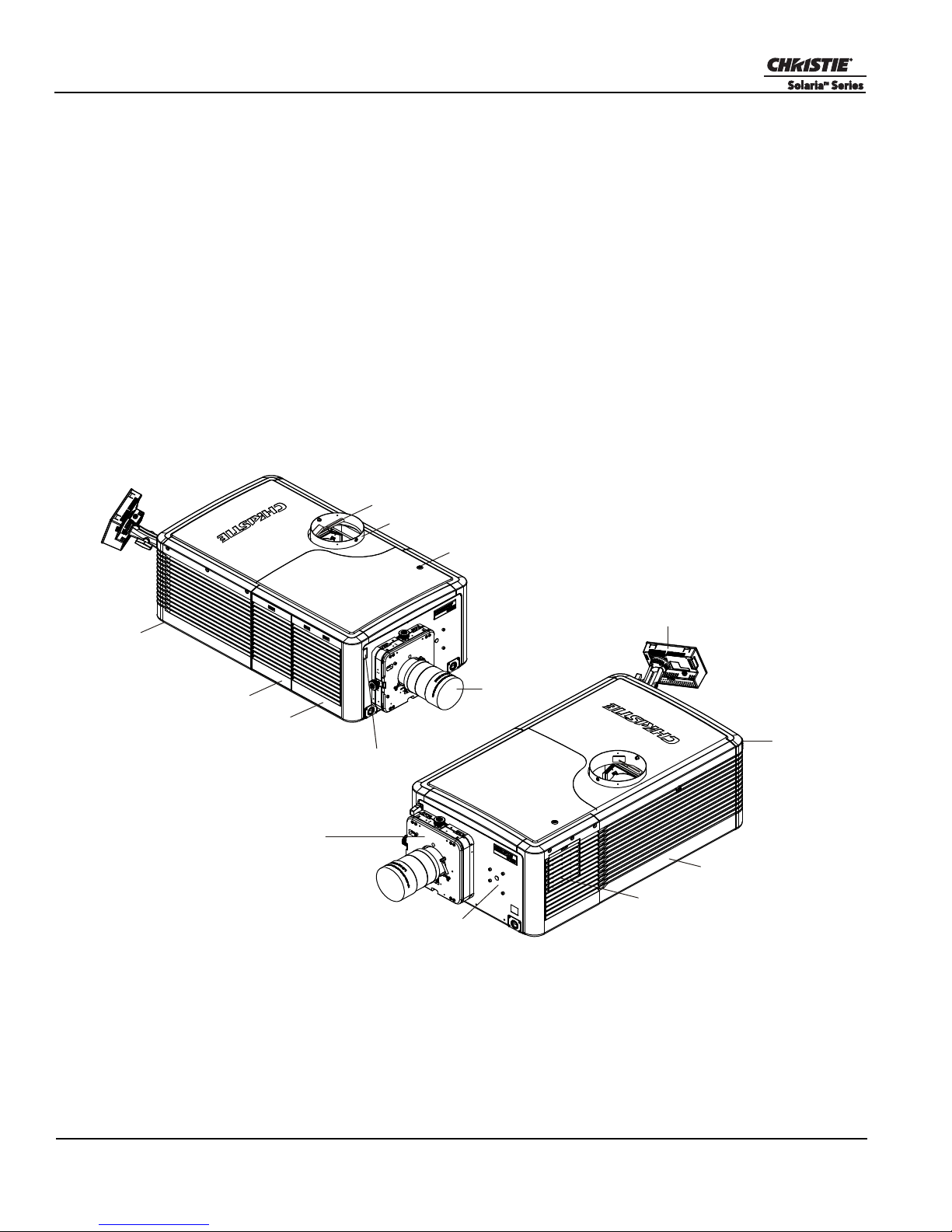
Figure 1-1 CP2220 Projector
The CP2220 is a professional quality, easy-to-use
DMD™ projector utilizing Digital Light
Processing (DLP™) Cinema technology from
Texas Instruments. It’s all-in-one design integrates
all components in a sleek projection head that can
be table-top mounted or used with the optional
rack stand. Integrating smoothly into traditional
projection environments such as theatres and other
wide screen exhibitor venues, the CP2220 offers
stunning wide screen, high-resolution cinema
images that remain flawless from first release to
final show. CP2220 interfaces with local networks
typical in theatres throughout the world, and can
be expanded even further by connecting noncinema DVI source material for multimedia
presentations from a variety of formats.
1.6.1 Key Features
Section 1: Introduction
• 2048 x 1080 native pixel format
• CineBlack™ and CinePalette™ for deep film-like blacks and superior colorimetry
• 2.0 or 3.0 kW Xenon lamps available
• Supports theatre screens up to approximately 40 feet in width
• Touch Panel Controller (TPC) running Windows XP for main projector interface. Ensure you have the latest
software by visiting www.christiedigital.com.
• Seamless switching between 292 and DVI inputs
• Capable of supporting an internal image media block
• One 10/100BaseT Ethernet port for connection to in-theatre Ethernet hub
• Two RS-232 ports for communication: one for Christie-supported peripherals (except Cine-IPM 2K) and one
for TI
• One GPIO port for control of automation
• One Simple Contact Closure Input (SCCI) for automated Lamp Start and Dowser operation
• Two DVI-D inputs for display of copy protected alternate content
• Two USB ports on the back of the TPC for direct laptop connection, useful during setup and local software
downloads
• One 3D port for interfacing to third-party 3D systems
• LiteLOC™ feature for constant image brightness
• LampLOC™ feature for motorized three-axis lamp alignment
• Electronically operated “quick” douser
• Motorizeable lens mount
• LED indicators on the rear corners of the projector for easy-to-read status indication
• Secure, encrypted communication protocol with multi-level password access
• High-security lock on SPB2 boundary for front electronics and content protection
• Low and medium-security locks or captive fasteners on access doors for internal maintenance
CP2220 User Manual 1-5
020-100420-06 Rev. 1 (03-2011)
Section 1: Introduction
Touch Panel Controller (TPC)
LED Status
Indicators (x 2)
Lamp Door
Liquid Cooling Air Filter / Cover
Lens Mount
(with option to motorize)
Mounting for Motorized
Auxiliary Lens Mount (MALM)
RS-422 Connector
(for connection of optional
motorized lens mount)
Vane Switch
Source and Communication Panel
Adjustable Feet (x4)
Light Engine Air Filter / Cover
Exhaust Duct
Top Lid Access
Projection Lens
Figure 1-2 Projector Overview
• Replaceable air filters (no tools required)
• Capability to split power supply for use of Uninterruptible Power Supply (UPS) to power head electronics
• Optional Rack Mount Stand
• Choice of field-interchangeable zoom lenses and anamorphic lenses
• Optional Motorized Auxiliary Lens Mount for anamorphic or auxiliary lenses
1.6.2 How the Projector Works
The CP2220 accepts a variety of cinema or DVI-compatible “non-cinema” signals for projection on front
screens typical in commercial theatre or other large screen applications. High-brightness light is generated by a
short arc Xenon lamp, then modulated by three Digital Micromirror Device (DMD) panels responding to
incoming data streams of digitized red, green and blue color information. As these digital streams flow from
the source, light from the responding “on” pixels of each panel is reflected, converged and then projected to the
screen through one or more front lenses, where all pixel reflections are superimposed in sharp full-color
images.
1.6.3 Projector Components - Overview
1-6 CP2220 User Manual
020-100420-06 Rev. 1 (03-2011)

Section 1: Introduction
Air Filter Cover and Air Filter
Located directly behind the air filter cover is a field replaceable air filter. The air filter is responsible for
filtering the intake air before it begins circulating in the front compartment to cool the main electronics.
Replace the air filter whenever the lamp is replaced or sooner in dusty/dirty environments. Check the condition
monthly. Refer to 4.4.8 Air Filter Replacement, on page 4-10 for complete instructions.
Manual Douser Override
For most instances, use the douser control buttons on the TPC to blank the display for instant picture muting.
Closing the douser rotates a shutter blade in front of the illumination system and reduces lamp power to 2kW
to conserve lamp life. Using the switch at the back of the projector has the same affect, however it is not
reflected in the TPC. The switch is meant for emergency use only.
Exhaust Duct and Vane Switch
Located at the top of the projector is a 8” diameter exit port where heated air from cooling the lamp is extracted
by an external heat extraction system provided by the installation site. Inside the rigid port is a vane switch
which detects and monitors the amount of airflow at the opening.
Refer to 2.1 Site Requirements, on page 2-1 for airflow requirements of the external heat extraction system.
Adjustable Feet
For most cinema installations, the projector is inclined slightly forward to match screen tilt and to minimize the
amount of vertical offset required. Turn the adjustable feet to increase or decrease the projector height as
needed for proper leveling and/or slight tilt. Refer to Adjusting Feet/Leveling, on page 2-4 for details on how
to adjust the feet and how to properly secure the projector with the mandatory safety strap or optional lock
down foot for use with the rack stand before making such adjustments.
Lamp Door and Lamps
Located on the non-operator’s side of the projector (right side when facing the front of the projector) is the
lamp access door designed with a mid-security lock. The lamp door must remain closed and locked for all
normal operation. Lamp replacement should only be performed by qualified technicians.
The projector is designed to operate with 2.0kW and 3.0kW lamps. For a complete list of available lamp types
refer to Section 6 Specifications.
LED Status Indicators
Located in the rear corners of the projector are two sets of LEDs, which illuminate to provide continuous
feedback of the projector’s status. Refer to 3.1.3 Projector Power States, on page 3-2 for details on the various
LED states.
Motorized Auxiliary Lens Mount (optional)
An optional auxiliary lens mount can be installed adjacent to the primary lens mount to provide motorized
positioning of a 1.25x Anamorphic lens or a 1.26 Wide Converter lens in front of the primary lens. The Wide
Converter lens “zooms” the image from flat to scope image formats. The Anamorphic lens horizontally
spreads the image back into its wider 2.39:1 “scope” image and is most typically used in side-masking theatres
or on larger screen sizes.
CP2220 User Manual 1-7
020-100420-06 Rev. 1 (03-2011)

Section 1: Introduction
Projection Lens
A variety of lenses can be used with the CP2220. Refer to the Section 6 Specifications for a list of available
lenses.
RS-422 Connector
The RS-422 connector located on the front bezel is dedicated for the electrical connection of the optional
Motorized Lens Mount.
Security Locks
Critical internal components and/or connections are protected by various security locks on projector covers.
The projector’s covers cannot be removed with standard tools unless the key locks are open. This safeguard
enables only authorized personnel to access and service components in these restricted areas.
Panels with high-security lock: Inside Security Boundary Lid on light engine (also called the SPB2)
Panels with mid-security lock: Top Lid, Lamp Door
No locks: Air Filter Access Panel (x2), Source and Communication Panel
Source and Communication Panel
Located on the operator’s side of the projector (left side) is a communication panel that provides connection of
external devices such as servers and a controller.
PIB Faceplate Connections:
• Ethernet: Use the 10Base-T/100Base-TX Ethernet port for network connection to the projector.
• GPIO: Connect external I/O devices, such as the Christie ACT, for remote control of a limited number of
projector functions. Refer to Appendix D: GPIO Port for GPIO pinouts.
• DVI-A / DVI-B: Connect a variety of non-cinema video and graphics sources to either of these identical sin-
gle-link DVI ports. These are single-link ports for single-link cables/connectors only. The connectors can be
used together as a twin-link DVI port.
• HD-SDI A/HD-SDI-B: Connect a variety of high-definition cinema sources to these SMPTE 292M bit-
serial standard interface BNCs. The connectors can be used together to deliver Dual Link HD-SDI following
the SMPTE 372M standard.
• SCCI: A Simple Contact Closure Interface (SCCI) port that provides the following functions upon a simple
dry contact closure: Lamp On/Off and Douser Open/Closed. Refer to Appendix C: SCCI Port for SCCI pinouts.
• RS232 ICP: Connect a PC or laptop for direct DLP communication. Trained users required.
• RS232 PIB: Utilizes Christie-proprietary protocol and is intended for Christie accessories or third-party
automation equipment.
• Marriage: Marriage must be established to allow the projector to play encrypted content. This means the
security boundaries SPB1 and SPB2 are physically and electrically connected and that marriage is monitored
24/7. Marriage is initiated from a Wizard application on the TPC. A user with the appropriate credentials is
prompted to press the marriage button to establish marriage. If the button is pressed any other time it is
ignored. Marriage cannot be established remotely.
• Emergency Start: This button is recessed into the faceplate to prevent accidental activation. It should only
be used when the TPC has failed or is disconnected. When pressed, the projector is powered on, the lamp is
turned on and the douser is opened. When you press and hold this button, the douser is closed and the lamp is
turned off, but power is still on.
1-8 CP2220 User Manual
020-100420-06 Rev. 1 (03-2011)

Section 1: Introduction
• Reset: This button is slightly recessed into the faceplate to prevent accidental activation. It’s main purpose is
to reset the electronics of the projector. After re-booting, the projector will return to its previous power mode
(Standby or Full Power), however the lamp will not strike automatically and requires manual striking.
• 3D: Connect a variety of 3D products to this connector, such as MasterImage or Real D for polarizing and
de-ghosting 3D content during projection.
ICP Faceplate Connections
The ICP board provides the image processing electronics for the projector. The ICP faceplate includes a
number of LEDs that are only functional when the projector is in full power mode.
• REGEN: (Regulators Enabled) This LED indicates the presence of the internal regulator enable signal.
When illuminated BLUE the internal regulators are enabled. When OFF, not enabled.
• SOFTST: (Software State) This LED indicates the state of the software application. When OFF, in a Fail
state (0). When RED, in a Fail state (1). When YELLOW, in a Fail state (2). When GREEN, status OK.
• OSST: (Operating System State) This LED indicates the state of the operating system. When OFF, in a Fail
state (0). When RED, in a Fail state (1), When YELLOW, in a Fail state (2). When GREEN, status OK.
• FMTST: (FMT FPGA State) This LED indicates the configured state of the FMT FPGA. When RED,
unable to configure FPGA with Main or Boot application. When YELLOW, in Boot application. When
Green, in Main application.
• ICPST: (ICP FPGA State) This LED indicates the configured state of the ICP FPGA. When RED, unable to
configure FPGA with Main or Boot application. When YELLOW, in Boot application. When Green, in Main
application.
• Port A / Port B: Indicates the status of the ICP input port A or B. When OFF, no source is present. When
GREEN, active source present.
Touch Panel Controller (TPC)
The Touch Panel Controller (TPC) is a portable, touch-sensitive screen used to control the projector. It is
mounted to the rear of the projector and can be adjusted at any angle using the flexible double ball joint mount
for convenient viewing and flexible operation in various installation configurations. In general, the TPC
provides users with a means for monitoring operation and status of the projector. In general, users can turn the
lamp on/off, select a specific source/input, and obtain basic status information.
Depending on the installation, the TPC can remain mounted to the projector or wall mounted anywhere else at
the site. An optional extension cable is also available, which can be purchased separately to provide TPC
access up to 100 feet away.
1.6.4 List of Components
Ensure the following components were received with the projector:
Projector with Touch Panel Controller
Lens plug
Nylon safety strap with clip
Warranty Card
Web Registration Form
Ensure the following components were received with the Lamp Power Supply (P/N 127-101103-01):
10’ line cord (250V/10A)
Harness package (includes 4 cables)
(required for shipping when lens is not installed to prevent contamination of critical optical components)
(required to secure projector to tabletop or optional rack mount)
CP2220 User Manual 1-9
020-100420-06 Rev. 1 (03-2011)


2 Installation and Setup
This section explains how to install, connect and optimize the projector for delivery of superior image quality.
NOTE: Illustrations are graphical representations only and are provided to enhance the understanding of the
written material.
2.1 Site Requirements
The following site requirements are required for safe installation and operation of the CP2220:
Physical Operating Environment
• Maximum Ambient Temperature (operating) 35°C
• Minimum Ambient Temperature (operating) 10°C
External Exhaust Ducting
• The installation site must provide a minimum of 450 CFM (ft 3/min) external exhaust airflow to ensure adequate cooling of the projector’s Xenon arc lamp at less than or equal to 25°C ambient and less than 3,000 feet
elevation. Above 25°C or 3,000 feet, 600 CFM is required. For detailed instructions on how to measure CFM
refer to STEP 5 - Connect External Exhaust Ducting, on page 2-5.
Permanent Power Connection
• A 30-32A double pole, UL listed wall circuit breaker is required. It must be part of the building installation
and easily accessible.
• Single-phase 30A connection of AC supply to the terminal block.
• Protection from overcurrents, short circuits and earth faults must be part of the building installation. The disconnect device (double pole switch or circuit breaker with minimum 3mm contact gap) must be readily
accessible within the projection room.
Refer to STEP 8 - Connect Power, on page 2-8 for detailed instructions.
2.2 Tools Required for Installation
Before you begin installation, it is important to fully understand all site requirements and characteristics, and
that you have the following tools and components on hand.
12” screwdrivers: Phillips #2 (magnetic) and flat
19mm and 7/8” wrenches
Assorted Allen keys (metric)
Heat extractor
Protective clothing/safety gear (required when handling the lamp)
Lamp
Lens cleaning tissue and solution
CP2220 User Manual 2-1
020-100420-06 Rev. 1 (03-2011)

Section 2: Installation and Setup
WARNING
2.3 General Installation Safety and Warning Guidelines
• QUALIFIED TECHNICIAN REQUIRED for all installations. This product must be installed in a
restricted access location.
• Never operate the projector without all of it’s covers in place.
• Projector uses a high-pressure lamp that may explode if improperly handled. Always wear
manufacturer approved protective safety clothing (gloves, jacket, face shield) whenever the
lamp door is open or while handling the lamp. Lamp installation/replacement requires a
qualified technician.
• Use of the projector’s rear safety strap is MANDATORY to prevent it from tipping.
• Four or more people are required to safely lift and hand-carry one projection head a short
distance. Recommend removing the lamp before transporting the projector.
• Keep the projector as level as possible when lifting or transporting. Avoid tilting the projector on the right side. This can introduce an air bubble within the coolant hoses that can lead
to an air lock.
• Perform Auto LampLOC™ whenever the projector is physically moved or leveled or whenever a new lamp is installed.
2-2 CP2220 User Manual
020-100420-06 Rev. 1 (03-2011)
2.4 Installation Instructions
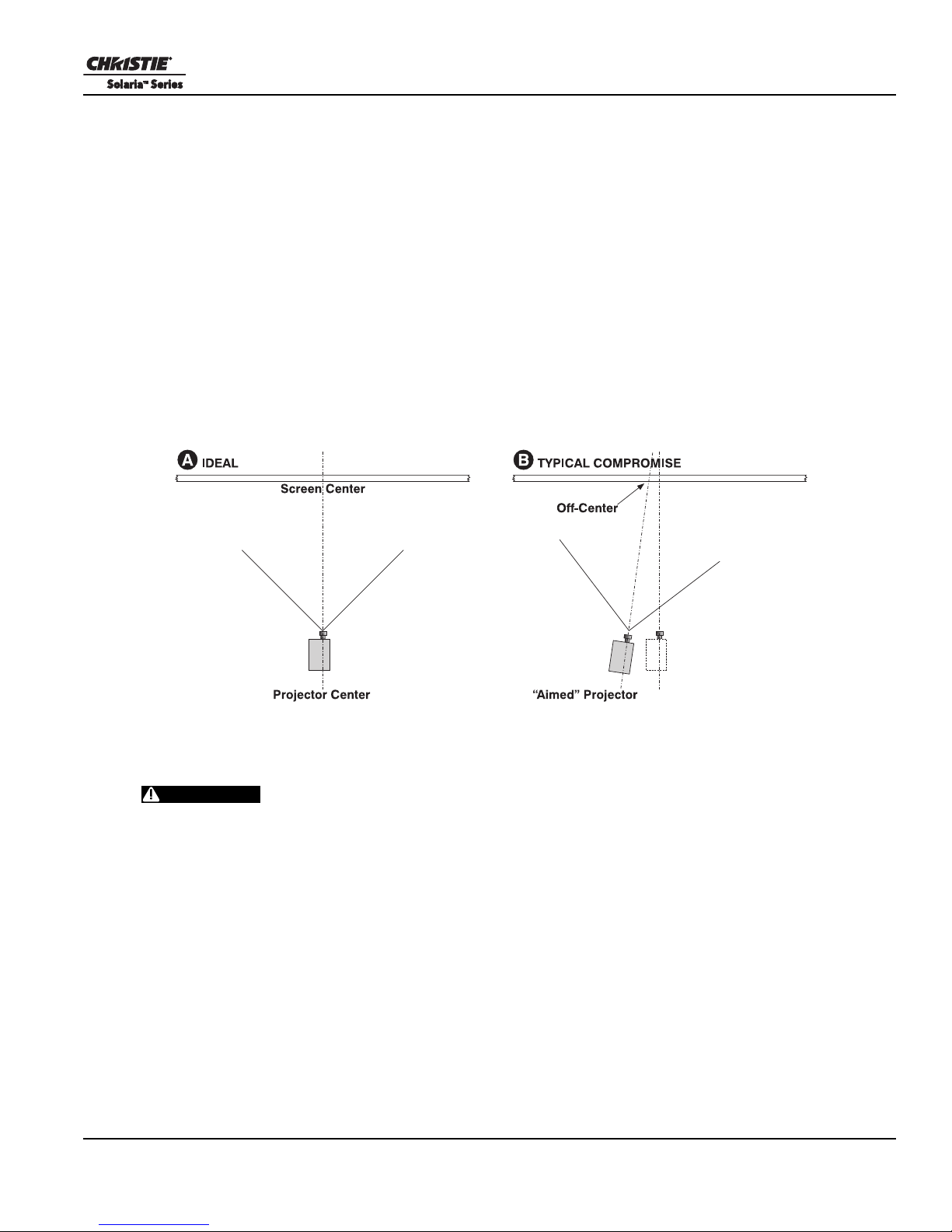
Figure 2-1 Position the Projector
WARNING
STEP 1 - Position the Projector
1. An optional rack stand (P/N 108-282101-02) and hold down clamp (P/N 116-100101-01) are available for
use with the projector. If you intend to use the rack stand as part of your installation, refer to the
instructions provided with the rack stand before continuing with the remaining installation steps.
2. Position the projector at an appropriate throw distance (projector-to-screen distance) and vertical position.
Ideally, center the projector with the theatre screen. If competing for space with an already present film
projector, aim the projector slightly off-center as shown in Figure 2-1. This will slightly increase side
keystoning, but will minimize the horizontal lens offset required.
NOTE: Unlike film projectors, it is best to keep the projector lens surface as parallel to the screen as possible, even if significantly above the screen center. When a particularly short throw distance combines with
a very wide screen, you may have to forfeit some aim and stay more parallel to the screen. In such cases,
some lens offset can reduce the keystone distortion.
Section 2: Installation and Setup
STEP 2 - Secure the Projector
Use of the projector’s rear safety strap is MANDATORY to prevent it from
tipping. Secure the strap between the projector and the optional rack-mount or any other
surface it is mounted to.
Attach the supplied safety strap to the back of the projector and fasten it to its mounting surface. Use of the
strap is mandatory to prevent the projector from tipping when a lens or auxiliary lens mount is installed.
NOTE: If you are using the optional rack stand, it is strongly recommended you use the hold down clamp
(116-100101-01) in addition to the rear safety strap to firmly secure the projector’s rear feet.
STEP 3 - Adjust Tilt/Leveling
For an ideal installation, the CP2220 lens surface should be centered and parallel to the theatre screen. This
orientation helps to ensure optimized lens performance with minimal offset. Choose a sturdy mounting surface
that allows for this. If this position is not possible (such as when the projector is significantly higher than the
center of the screen), it is better to rely on offset rather than extra tilt.
Check with theatre personnel for the degree of screen tilt or measure this incline with a protractor at the screen.
Tilt the projector to match the screen tilt angle by extending or retracting the projector’s four adjustable feet.
CP2220 User Manual 2-3
020-100420-06 Rev. 1 (03-2011)

Section 2: Installation and Setup
Figure 2-2 Adjust Feet
Figure 2-3
Figure 2-4
NOTES: 1) For best optical performance, avoid tilting the projector
excessively. Use vertical offset of the lens instead. 2) The front-to-back tilt of
the projector must not exceed 15°. This limit ensures safe lamp operation
and proper position of the liquid cooling reservoir in the projector.
Adjusting Feet/Leveling
To adjust the height or level of the projector, extend or retract the adjustable
feet located on the bottom of the projector by rotating them. Once the
required adjustment is made, tighten the lock nut. See Figure 2-2.
WARNING! Make sure the projector’s rear safety strap is in
place before adjusting the projector’s feet.
STEP 4 - Mount Touch Panel Controller (TPC)
The TPC comes pre-assembled with its base and mounting arm. It is shipped separately and must be mounted
to the projector during installation.
When installing the TPC:
1. Loosen the mounting arm just enough for the end to fit over the ball joint located on the rear panel of the
projector. Figure 2-3
2. Tighten the mounting arm until it fits snug on the ball joint. Figure 2-4
3. Connect the cable from the TPC to the connector located on the projector’s rear panel.
4. Adjust the angle of the TPC as desired.
2-4 CP2220 User Manual
020-100420-06 Rev. 1 (03-2011)
Section 2: Installation and Setup
Exhaust
Duct to
Outside
450 cfm
required*
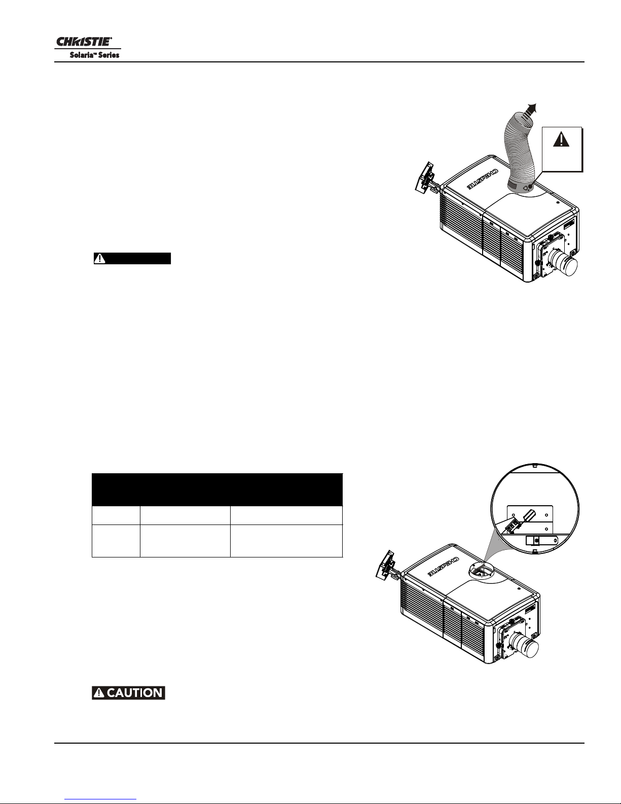
Figure 2-5 Connect Exhaust
Ducting
WARNING
Top View into
Exhaust Duct
Vane Switch
Figure 2-6 Exhaust Duct Vane Switch
STEP 5 - Connect External Exhaust Ducting
The projector emits a constant stream of warm exhaust air, which must
be vented to the outside of the building. Connect the site’s preinstalled, outside-venting ductwork via the 8” diameter exhaust port
on the top of the projector. Confirm that 1) there are no obstructions or
‘kinks” within the ducting, 2) all air intake areas of the projector are
clear and exposed, 3) the vane switch at the exit duct is moving freely.
The site’s pre-installed outside-venting duct should be rigid at the
projector and must also include a heat extractor/blower that maintains
a minimum of 450 CFM* when the projector is operating at less than
or equal to 25°C ambient and less than 3,000 feet, while measured at
the projector exhaust opening.
• *600 CFM is required in projection rooms with ambient
temperature above 25°C or elevation (above sea level)
greater than 3000 feet.
• At minimum, a 10” long, strong metal duct must be in place at the projector to prevent
glass shards from exiting the duct in the event of a lamp explosion.
How to Calculate CFM in the 8” diameter external exhaust duct:
Use an airflow meter to measure the ft/min or ft/sec at the rigid end of the open exhaust duct that will connect
to the projector. Make sure the measurement is taken right at the very end without the projector connected.
Then multiply the reading by the cross-sectional area of the 8” duct to calculate the cubic feet/min airflow. The
formula is:
Measured linear ft/min x 0.35 = CFM
Table 2.1 Installation Requirement Calculations
Airflow
(CFM)
450 CFM
600 CFM
Temperature
25°C or lower at or below 3000 feet
greater than
25°C
and below 35°C
Add an extractor/boosters as needed for your site, as the vane
switch will prevent the projector from operating if there is
insufficient airflow. Do not mount the extractor on the
projector as this may introduce some vibration into the image.
NOTE: If the duct becomes significantly blocked - or if a fan
fails - the projector should trigger an alarm before becoming
overheated or unsafe. Regardless, check airflow regularly.
For instructions refer to Airflow Interlocks, on page 4-6.
Altitude (above sea
level)
at or below 10 000
feet
Never disable the vane switch.
Attempting to operate the projector with inadequate airflow can result in dangerous overheating of the projector.
CP2220 User Manual 2-5
020-100420-06 Rev. 1 (03-2011)

Section 2: Installation and Setup
Clamp
Open
1.
Install Lens
Figure 2-7 Open Lens Clamp and
Insert Lens
Clamp
Locked
2.
Lock
Figure 2-8 Lock Lens In Place
STEP 6 - Install Lens
The lens seals the projector preventing contaminants from entering the area of the main front electronics.
CAUTION! Never operate a projector without a lens installed.
For Primary Zoom Lens Installation:
1. Ensure the projector’s rear safety strap or rear hold down bracket is in place.
2. Turn the lens clamp to the OPEN position. See Figure 2-7.
3. Orient your high-contrast lens with its notches at the top. Fully insert the assembly straight into the lens
mount opening without turning. When the lens is fully inserted it will seat properly within the lens mount
and the aperture will be oriented correctly. NOTE: Insert a high-brightness lens in the same manner, with
the UP label at the top.
4. Position the lens clamp DOWN to lock the lens assembly in place. See Figure 2-8.
5. Calibrate the lens. See 2.8 Basic Image Alignment, on page 2-17 for
details.
For Auxiliary Lens Installation (Optional):
To install a 1.26x Anamorphic lens or a 1.26x Wide Converter Lens (WCL)
producing 2.39:1 “scope” images for large screens, install the auxiliary lens
mount and lens to the projector using the hardware and instructions
provided in the Auxiliary Lens Mount Kit (P/N 108-111101-xx, P/N 108111102-xx).
Motorized Lens Mount Option
The lens mount on the projector is designed so that it can be motorized by
installing the optional Motorized Lens Mount Motors Kit (P/N 127102104-xx). This will give the lens mount motorized vertical, horizontal
and focus travel as well as zoom control. Refer to the instructions provided in the kit for installation of the
various stepper motors and motor control PCB.
2-6 CP2220 User Manual
020-100420-06 Rev. 1 (03-2011)

Section 2: Installation and Setup
DANGER
Reflector
Anode
Yoke
Assembly
5mm hex key
required
Figure 2-9 Anode Yoke Position
STEP 7 - Install First Lamp
Qualified technician required! High-pressure lamp may explode if improperly
handled. Always wear approved protective safety gear whenever lamp door is open or while
handling the lamp.
1. Open lamp door. Using the security key provided, open the lamp door and inspect the empty lamp cooling
compartment. Caution! Do not place heavy objects on the open lamp door.
2. Position anode yoke assembly according to lamp type. Check the position of the anode yoke assembly
for the lamp type that will be used in the projector. Table 2.2 lists all available lamp types for the CP2220
and the position of the anode yoke assembly. (Figure 2-9)
Table 2.2 Lamp Types Available for CP2220 and Anode Yoke Position
LAMP TYPE ANODE YOKE POSITION
2.0 kW CDXL-20 Move the lamp cradle as far forward as possible (position
3.0 kW CDXL-30
3.0 kW CDXL-30SD (short arc)
3.0 kW CXL-30
closest to igniter)
Move the lamp cradle to the rear position, which is approximately 1” closer to the reflector.
3. Install the lamp. Refer to 4.4.6 Lamp Replacement, on page 4-7 for lamp replacement instructions.
Observe all warnings, and wear protective safety gear.
Important! The projector is shipped with a lamp extension nut fastened to the cathode end of the lamp
holder. Use this nut with CDXL-30SD lamps only. This will ensure proper placement of this lamp type. If
you are installing any other lamp type, remove this nut and retain it for future lamp replacements by
threading it onto a dedicated stud located on the baseplate in the lamp compartment (labeled). Leaving the
extension nut on with the wrong lamp type can lead to extremely dim light output.
CP2220 User Manual 2-7
020-100420-06 Rev. 1 (03-2011)
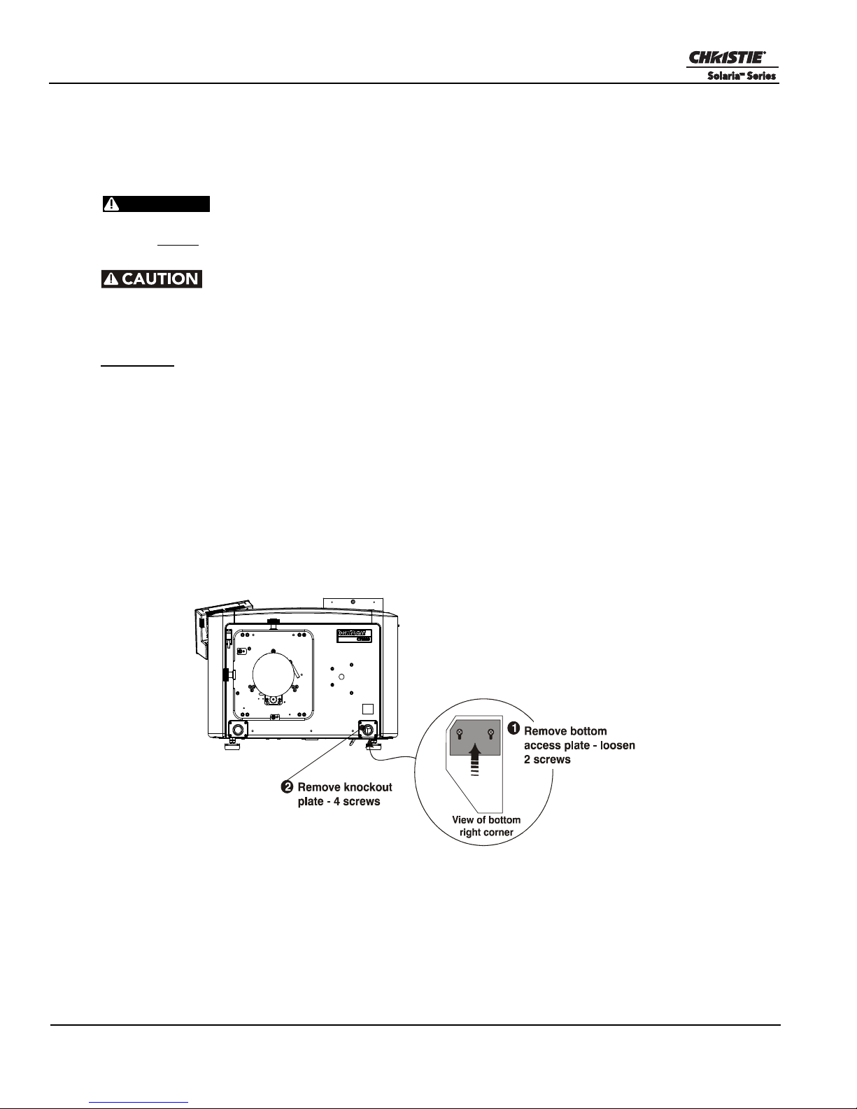
Section 2: Installation and Setup
WARNING
Figure 2-10
STEP 8 - Connect Power
CP2220 is designed as a permanently wired connection or pluggable type B connection. Connecting the
projector to your AC supply can vary according to the country or state in which the projector is installed. For
any installation, always follow the electrical code for your location.
=
1) Certified electrician required. 2) Ground (earth) connection is necessary for
safety. Never compromise safety by returning the current through the ground. 3) Connect
ground FIRST to reduce shock hazard from high leakage.
Use an appropriate strain relief connector on the AC supply cable to prevent
the cable from rubbing against the projector knockout plate and becoming damaged.
Installing a Permanent Connection
Guidelines:
A 30-32A double pole, UL listed wall circuit breaker is required. It must be part of the building
installation and easily accessible.
Use 10AWG or 8AWG wiring: The distance between the wall circuit breaker and the projector must
not exceed 20 metres using 10AWG cables or 30 metres using 8AWG cables.
For North American installations, use at least 10AWG copper wires for the connection of the main
AC supply to the projector’s ground lug.
Copper or aluminum are acceptable as conductor wiring material to the terminal block.
1. A small electrical access plate is located under the projector in the front right corner. Loosen the two
screws and slide the plate forward to expose the terminal block underneath. See Figure 2-10.
2. Remove the knockout plate located in the bottom right corner of the front bezel. The AC supply is routed
to the terminal block through an appropriate strain relief mounted on this knockout plate.
3. Optional, remove the terminal block for easier wiring (thumbscrews).
2-8 CP2220 User Manual
020-100420-06 Rev. 1 (03-2011)
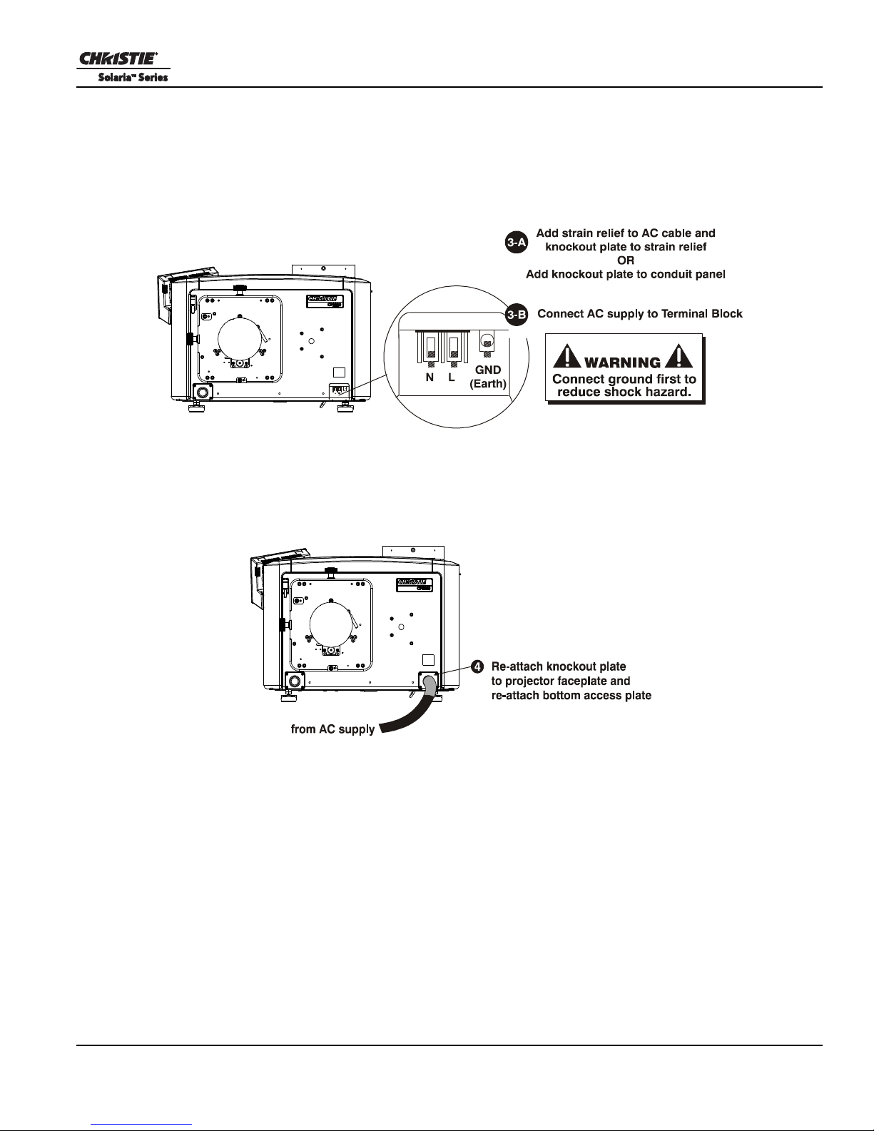
Section 2: Installation and Setup
Figure 2-11
Figure 2-12
4. Connect the AC power source to the terminal block, beginning with the ground lead first. See Figure 2-11
for wiring details. Use an appropriately sized strain relief connector with the knockout plate provided to
ensure adequate environmental sealing and to prevent the cables from wear and accidentally being torn
out. NOTES: 1) The terminal block accommodates up to an 8 AWG wire. 2) If desired, a 90° strain relief
connector can be used to route the power cable in a downward direction.
5. Once all cables are connected, replace the knockout plate and the bottom access panel over the terminal
block. (Figure 2-12)
CP2220 User Manual 2-9
020-100420-06 Rev. 1 (03-2011)
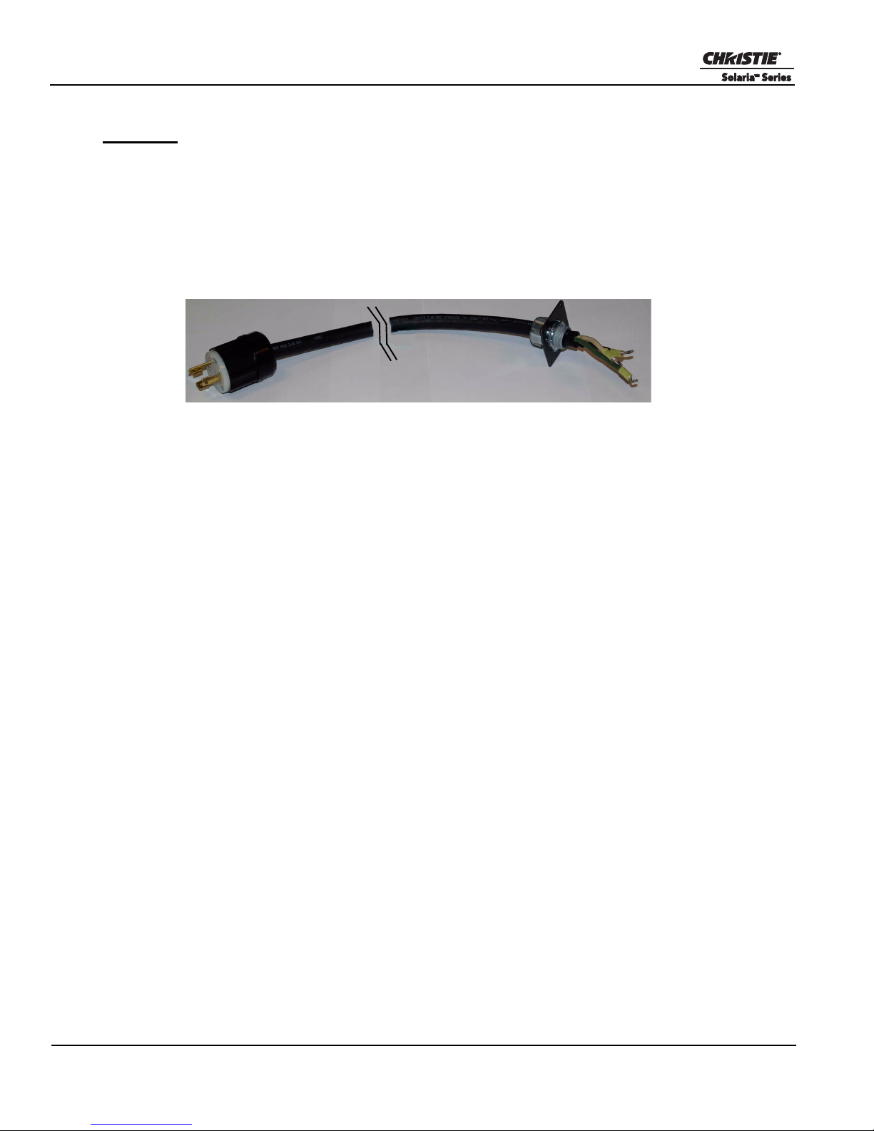
Section 2: Installation and Setup
Figure 2-13 Nema-L630A 250V Male Power Plug (
116-102104-01)
Actual Length 1.5 Meters
Installing a Pluggable Type B Connection
Guidelines:
There must be easy access to the current protection device or breaker in the building.
Use 10AWG or 8AWG wiring: the distance between the wall circuit breaker and the projector must
not exceed 20 metres using 10AWG cables or 30 metres using 8AWG cables.
The socket-outlet is installed near the equipment and is easily accessible.
The plug can be used as the device disconnect and is near the unit and easily accessible.
1. A small electrical access plate is located under the projector in the front right corner. Loosen the two
screws and slide the plate forward to expose the terminal block underneath. Figure 2-10
2. Remove the knockout plate (four screws) located in the bottom right corner of the front bezel.
3. Optional, remove terminal block for easier wiring (thumbscrews).
4. Connect the AC power source to the terminal block, beginning with the ground lead first. See Figure 2-11
for wiring details. Tighten screws securely.
5. Once all cables are connected, secure the knockout plate (four screws) and the bottom access panel (two
screws) over the terminal block.
2-10 CP2220 User Manual
020-100420-06 Rev. 1 (03-2011)
 Loading...