

Christie RPMX-D120U, RPMSP-D120U, RPMSP-D275U Setup Manual

RPMX/RPMSP-D120U
RPMSP-D275U
S E T U P G U I D E
020-100038-02

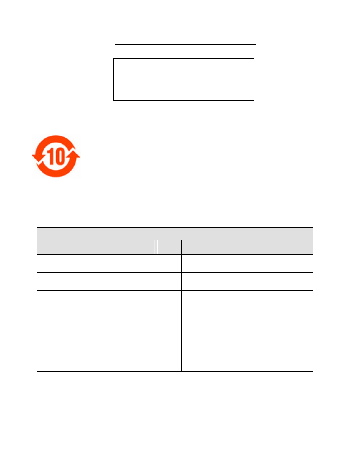
China RoHS Compliance Information
关于中国《电子信息产品污染控制管理办法》的说明
Applies to the Following Projectors
RPMSP-D120U
RPMX-D120U
RPMSP-D275U
• Environmentally Friendly Use Period
环保使用期限
The year number in the centre of the label indicates the Environmentally Friendly Use Period, which is
required to mark on the electronic information product sold in China according to the China RoHS
regulations.
本标志中表示的年数是根据《电子信息产品污染控制管理办法》(2006年2月28日)以及《电子信息产品污染控制标识
要求》(2006年11月6日)制定的、适用于在中华人民共和国境内销售的电子信息产品的环保使用期限。
• Material Concentration Values Table
有毒有害物质含量表
Part Name
部件名称
铅
(Pb) 汞 (Hg) 镉 (Cd)
Low voltage power
supply
Power & Ballast
Ten-bit image
processor module
TDOM PCB
Backplane module
Blower/Fan
Sensor
Illumination optics
system
Projection Lens
Auxiliary optics
Mechanical
enclosure*
Software CD
Lamp
Battery
Remote Keypad
Note:
O : indicates that the concentration value of the particular hazardous substance contained in all the homogeneous materials for this part,
according to EIP-A, EIP-B, EIP-C, is below the stipulated levels in China SJ/T11363-2006.
表示该有毒有害物质在该部件所有均质材料中的含量均在SJ/T11363-2006规定的限量要求以下。
X: indicates that the concentration value of the particular hazardous substance contained in all the homogeneous materials for this part,
according to EIP-A, EIP-B, EIP-C, may be above the stipulated levels in China SJ/T11363-2006.
表示该有毒有害物质至少在该部件的某一均质材料中的含量可能超出SJ/T11363-2006规定的限量要求。
* This part uses metallic alloys, which may contain Lead.
因该部件使用金属合金材料,故可能含有铅。
低压电源
电源及镇流器
十位图像处理模块
专用显示输出板
底板模块
吹风机/风扇
传感器
照明光学系统
投影镜头
辅助光学器件
机械附件
软件光盘
灯泡
电池
遥控器
X O O O O X
X O O O O X
X O O O O O
X O O O O O
X O O O O O
O O O O O O
O O O O O O
X O X O O O
X O X O O O
X O X O O O
X O O O O O
O O O O O O
X O X O O O
O O O O O O
X O O O O O
Material Concentration
(有毒有害物质或元素)
六价铬
(Cr 6+)
多溴联苯
(PBB)
多溴二联苯醚
(PBDE)


1 INTRODUCTION
2 INSTALLATION &
SETUP
3 OPERATION
4 MAINTENANCE
5 TROUBLESHOOTING
RPMX-D120U/RPMSP-D120U
RPMSP-D275U
Setup Guide
Table of Contents
1.1 Projector Overview ..........................................................................................1-1
1.2 Components .....................................................................................................1-2
2.1 Overview..........................................................................................................2-1
2.2 Pre-Installation & Consideration .....................................................................2-1
2.3 Installation & Setup .........................................................................................2-3
2.4 Connecting Sources .......................................................................................2-12
2.5 Connecting Communications.........................................................................2-15
2.6 Power Connection..........................................................................................2-21
3.1 Using the Keypad.............................................................................................3-1
3.12 Error Conditions ..............................................................................................3-7
4.1 Warnings and Safety Guidelines......................................................................4-1
4.2 Cleaning and Maintenance Guide....................................................................4-4
4.3 Replacing Remote Batteries.............................................................................4-5
4.4 Lamp Replacement ..........................................................................................4-5
5.1 Displays ...........................................................................................................5-1
5.2 Lamp ...............................................................................................................5-3
5.3 Ethernet............................................................................................................5-3
NOTE: Due to continuing research, all information in this manual is subject to
change without notice.
RPMX-RPMSP-D120U & RPMSP-D275U Setup Guide i
020-100038-02 Rev. 1 (09/08)

Section 1
Introduction
1.1 Projector
Overview
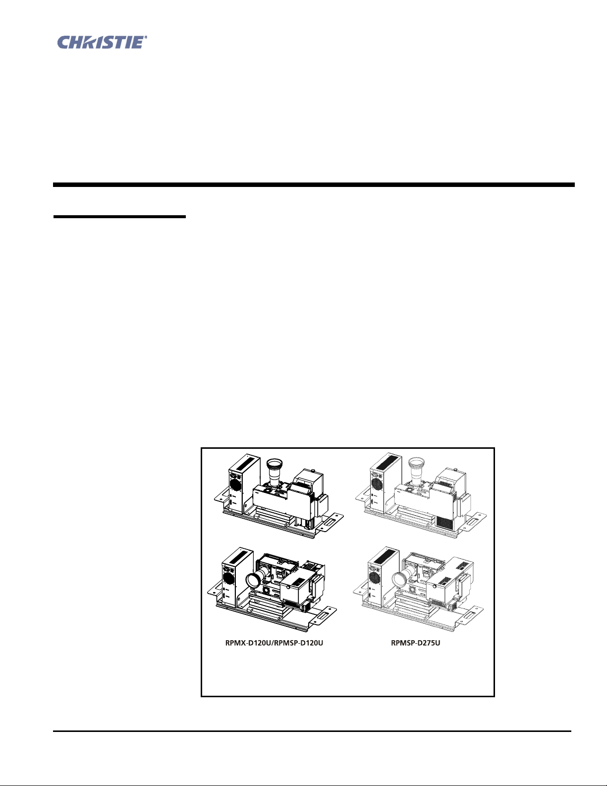
RPMX-D120U and RPMSP-D120U/D275U are professional quality XGA and
SXGA+ data projectors featuring the latest in DLP™ display technology to achieve
high brightness, high resolution multimedia and video projection images. These
projectors use Christie’s exclusive KoRE™ electronics and firmware to accept data,
graphics, and video input signals for projection onto flat, front or rear projection
screens.
The modular design of these projectors makes them an ideal choice for rear screen
projection and multi-display walls. With built-in flexibility, each projector is
configurable for straight throw or 90° mirrored applications. The unique 6-axis
adjustment mechanism enables accurate alignment of the lens to the screen
minimizing distortion at all corners and edges of the display.
A dual lamp (automatic changer) hot swappable system allows the projector to
operate for a long time before requiring a lamp change. The mechanical lamp
changer enables an automatic lamp change to occur when a lamp fails or whenever
requested by a user. The purpose-built design of these projectors makes them an ideal
choice for the demanding needs of 24/7 command and control centers,
telecommunications, surveillance and broadcasting applications.
Figure 1.1. The Projector
(SXGA+ shown, in both possible configurations)
RPMX-RPMSP-D120U & RPMSP-D275U Setup Guide 1-1
020-100038-02 Rev. 1 (09/08)

Section 1: Introduction
h
Key features (
See Section 6 for a complete list of product specifications.):
• RPMSP – Native SXGA+, 1400 x 1050 resolution
• RPMX – XGA, 1024 x 768 resolution
• 24-bit RGB display
• 10-bit image processing module
• Display of RGB, NTSC, PAL, and SECAM video inputs and HDTV formats
• User adjustable lamp power
• Mechanical lamp changer for easy lamp change during operation
• Picture-in-picture display
• Automatic calibration of display color settings
• Edge Blending ability via software for seamless displays
• Dual frequency IR sensor for use with standard IR remote and optional
long-range dual frequency remote
• Unique 6-axis image geometry adjustment mechanism
• Memory for up to 50 custom “channels” (source setups)
• Intuitive on-screen menu system
• Built-in GPIO port to enable active control of external devices
• LED display for projector status monitoring
• Multiple control options including RS-232 and RS-422
• On-board ChristieNET™ software
• Universal AC input 100-240 VAC, 50/60Hz
The user selects which lamp will be in operation through the Lamp Menu; Lamp
How the projector works
#1 or Lamp #2. After the lamp successfully ignites, the light generated is
sequentially filtered into the RGB color primaries by the spinning color wheel in
the light engine of the projector. This filtered light is then presented to the single
chip DMD, located in the light engine. The reflected light from the DMD chip
then passes through the projection lens to the screen to display the image.
1.2 Components
Ensure you have received the following components before using your projector.
5 Line Cord
5 Configuration bracket
5 Set of positioning tubes
enclosure)
5 6, M6 screws
*User’s Kit, which includes the following:
User’s Manual
IR Remote Keypad
Setup and Adjustment Tools
*NOTE: A User’s Kit is provided with each projection system. Additional
User’s Kits can be purchased separately (part number 102-138101-01).
Additional Tools Required
In addition to the contents of the user kit, it is recommended the following tools
be kept on hand during installation and setup:
#1 Phillips screwdriver
Level
1-2 RPMX-RPMSP-D120U & RPMSP-D275U Setup Guide
020-100038-02 Rev. 1 (09/08)
(rated, North American)
(shipped loose, for horizontal configuration)
(required when installing projector into CC50/CC67 cube
(for installation of configuration bracket)
---- ---- ----
(with batteries)
(includes 2mm and 5mm ball drivers, 8mm hex
ball driver, nylon spacers, lint free gloves)

2.1 Overview
Section 2
Installation & Setup
Use the information in this section to successfully install and setup your projector. In
general, the following steps must be completed:
Step 1 – Unpack the projector.
Step 2 – Select and modify the projector’s configuration based on the intended
application: lens-vertical (90 degree) or lens-horizontal (0 degree)
projection.
Step 3 – Calculate throw distance. Position and mount the projector.
Step 4 – Connect sources.
Step 5 – Turn the projector ON.
Step 6 – Adjust projection lens to improve image focus.
Step 7 – Adjust image geometry using the 6-axis adjuster.
Step 8 – Adjust software to optimize image on a single screen, or multiple screens.
NOTES: 1) The illustrations used in this manual are graphical representations only
and may not depict your projector model exactly. 2) If you are installing your
projector in a TotalVIEW™ 50” or 67”cube enclosure, refer to the separate
installation guide provided.
2.2 Pre-Installation
Considerations
Proper installation of your projector will ensure the quality of your display. Whether
installing your projector permanently or temporarily take the following into account
to get the best possible performance from your projector.
When designing a projection room, various factors need to be considered such as, are
you operating single or multiple units, room size, lighting and audience seating. All
of these factors must be taken into account in order to achieve the best possible
projector output. The most important factor to consider is the human factor – the
audience. Data gathered by answering questions like, “How far is the audience sitting
from the display?” and “From which angle will the display be viewed?” are important
first questions to ask yourself when deciding where to place the display, or what type
and size of screen to use.
RPMX-RPMSP-D120U & RPMSP-D275U Setup Guide 2-1
020-100038-02 Rev. 1 (09/08)

Section 2: Installation & Setup
Screen Size and Type
h
Choose a screen size most appropriate for your lens and application. Keep in
mind if the intended use of the projector is to display text information, the image
size must be large enough to allow the audience to view all text clearly. The eye
usually sees a letter clearly if eye-to-text distance is less than 150 times the
height of the letter. Small text located too far from the eye may be illegible at a
distance no matter how sharply and clearly it is displayed.
To fill a screen with an image, the aspect ratio of the screen should be equal to
the aspect ratio of the image. The aspect ratio of an image is expressed as the
ratio of its width to its height. It is best to choose a screen with a screen aspect
ratio most appropriate for your intended application. Screens with an aspect ratio
of 5:4 are recommended for use with these projectors.
There are two types of screens that are best suited for rear screen installations:
diffused and optical. A diffused screen has a surface, which spreads the light
striking it. Purely diffused screens have a gain of less than 1. Optical screens take
light from the projector and redirect it to increase the light intensity at the front of
the screen.
Ambient Lighting
Other Considerations
The high brightness of this projector is well suited for locations where ambient
h
lighting might be considered less than ideal for projection. A typical room with
ceiling lights and windows rarely requires special attention. Contrast ratio in your
images will be noticeably reduced only if light directly strikes the screen, such as
when a shaft of light from a window or floodlight falls on the image. Images may
then appear washed out and less vibrant.
In general, avoid or eliminate light sources directed at the screen.
Other considerations and tips that can help improve your installation:
h
• Ventilation is an important factor when preparing a projection room. The
ambient temperature should be kept constant and below 35°C (95°F).
Keep the projector away from heating and/or air conditioning vents.
Changes in temperature can cause drifts in the projector circuitry, which
may affect performance.
• Keep the projector away from devices, which radiate electromagnetic
energy such as motors and transformers. Common sources of these are
slide projectors, speakers, power amplifiers, elevators, etc.
• Use an optical mirror for rear screen installations to shorten the optical
light path and use less space in the projection room.
• When designing a projection room, consider positioning the projector
and screen where maximum audience coverage and space efficiency is
achieved. For example, placing the screen along the larger wall in a
rectangular room reduces audience coverage.
2-2 RPMX-RPMSP-D120U & RPMSP-D275U Setup Guide
020-100038-02 Rev. 1 (09/08)
Section 2: Installation & Setup
2.3 Installation &
Setup
Step 1 h
The following subsection outlines the steps necessary to complete the installation of a
RPMX/RPMSP-D120U and the RPMSP-D275U projector as a stand alone or
multiple projector installation.
For instructions on how to install your projector into the TotalVIEW™ 50” or 67”
cube enclosure, refer to the separate Cube Installation Manual provided in the User’s
Kit.
Unpack the projector
The projector is carefully packaged and shipped fully assembled in the lens-vertical
(90 degree) configuration. When you receive your projector it is important you do the
following to prepare it for installation:
• Remove the projector from the box and discard any packing material
surrounding the modules. Note: An L-shaped bracket, used to change the
projector’s configuration, is shipped loosely in the box with the projector. Set
this aside for future use.
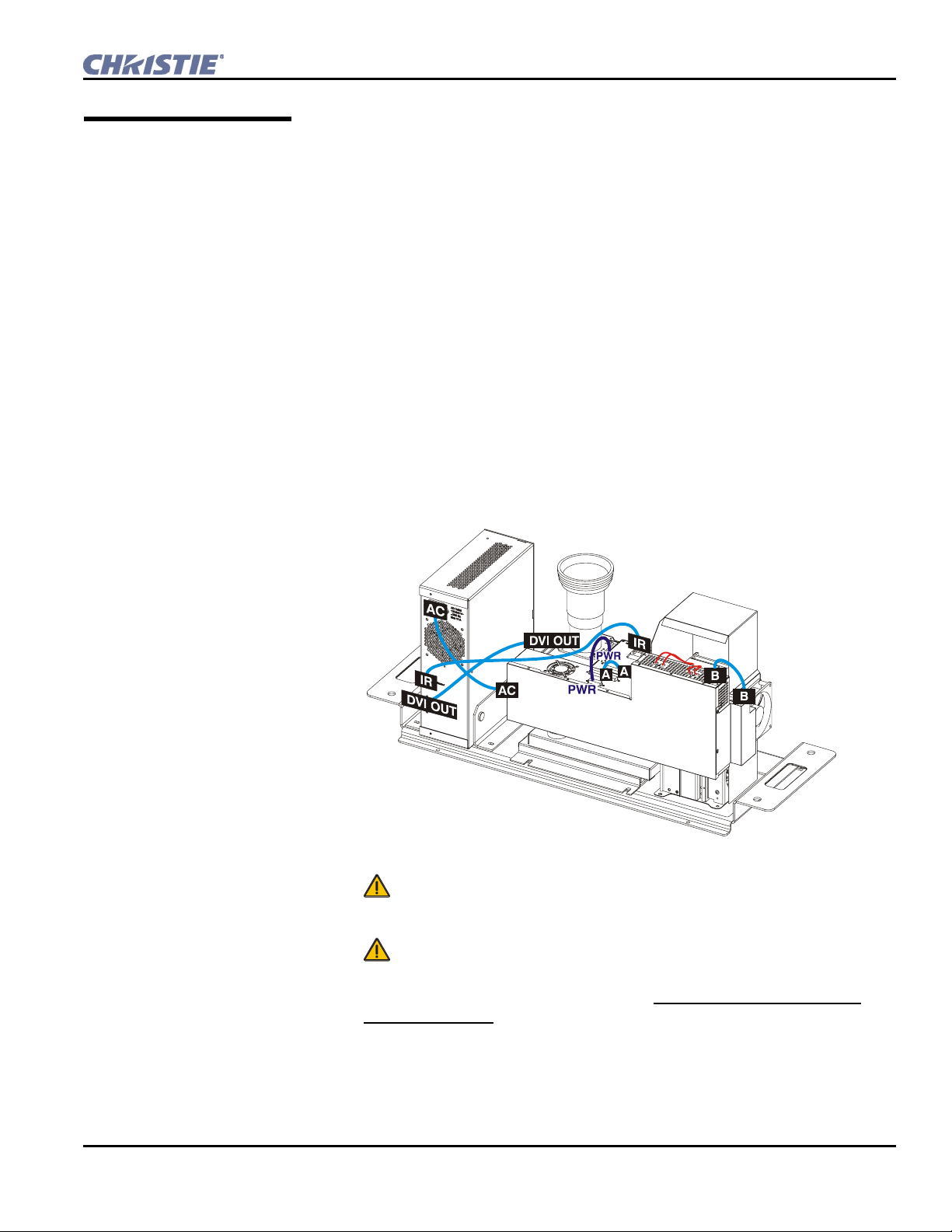
• Ensure all cable connections are secure. Reconnect any cables that may have
come loose during shipping. See Figure 2.1.
Figure 2.1. Internal Cable Connections
• Check lamp handles. These handles must lay flat against the lamp
surface otherwise they will interfere with lamp operation.
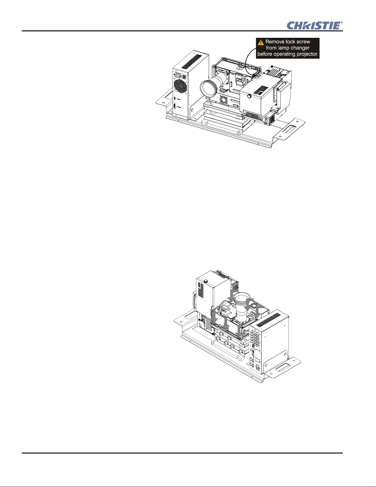
•
Remove the lock screw located on the mechanical lamp changer.
(Figure 2.2.) This screw is used for shipping purposes only and must be
removed prior to turning the projector on. Failure to do so can result in
projector damage.
RPMX-RPMSP-D120U & RPMSP-D275U Setup Guide 2-3
020-100038-02 Rev. 1 (09/08)
Section 2: Installation & Setup
h
Figure 2.2. Remove Lamp Changer Lock Screw
Step 2
Modify projector configuration (if required)
If you are planning on using your projector for lens-horizontal projection then
you must change its configuration. The L-shaped bracket and M6 screws shipped
with the projector are needed to complete this configuration change.
1. Ensure the projector is not plugged into AC.
2. Disconnect all cable connections made between the light engine and
electronics module. All disconnects should be made on the light engine
side.
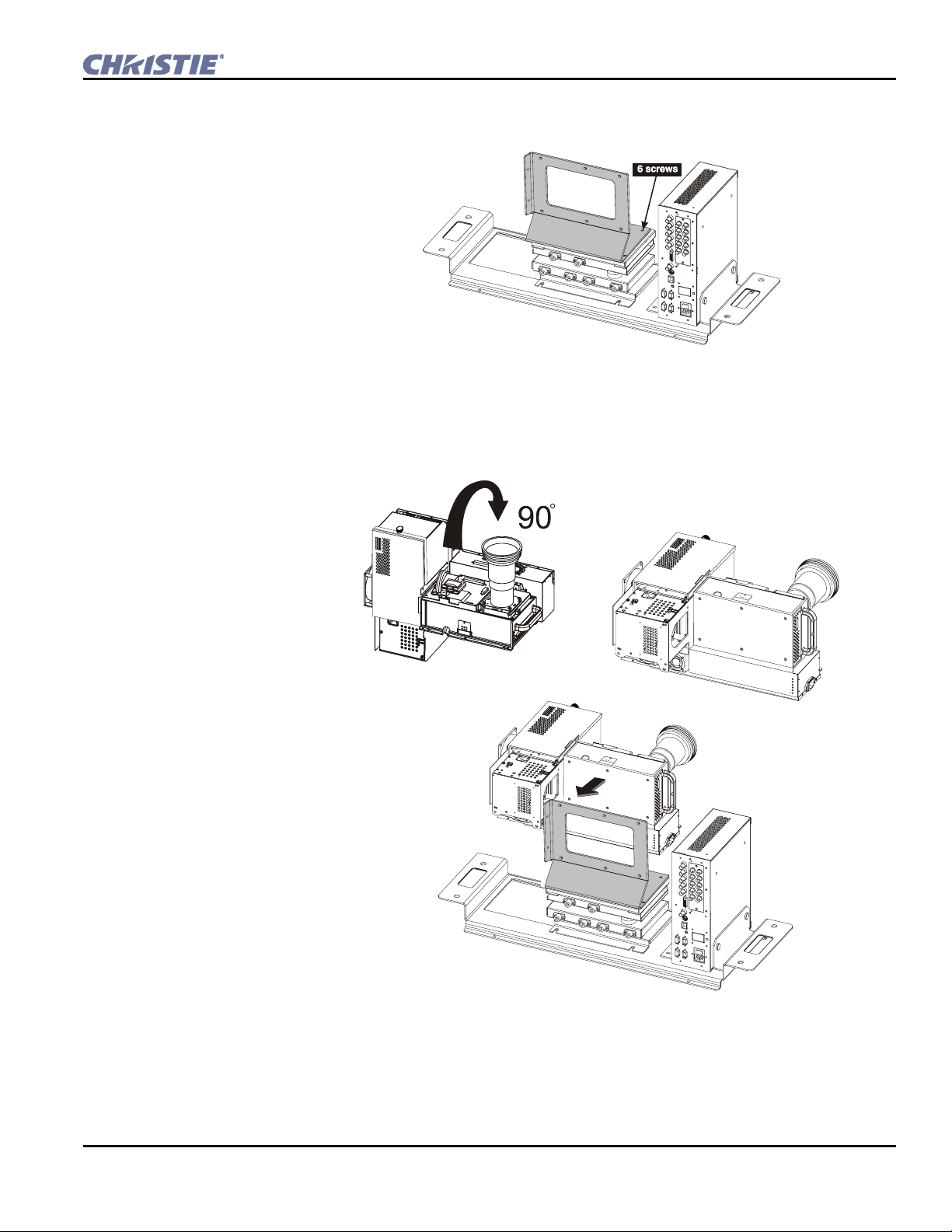
3. Remove the 6, M4 screws securing the light engine module to the 6-axis
adjuster.
Figure 2.3. Loosen Light Engine
4. Lift the light engine off the adjuster and set aside.
5. Take the L-shaped configuration bracket and align the shorter end with
the mounting holes in the adjuster base, as shown in Figure 2.4. The long
vertical part of the bracket will face the same side as the connectors on
the electronics module.
2-4 RPMX-RPMSP-D120U & RPMSP-D275U Setup Guide
020-100038-02 Rev. 1 (09/08)
Section 2: Installation & Setup
6. Secure the bracket to the adjuster base with the same 6, M4 screws used to
secure the light engine.
Figure 2.4. Install configuration bracket to adjuster base
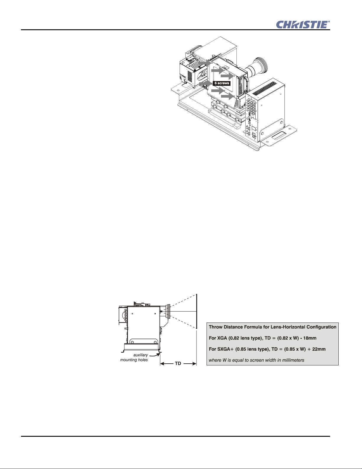
7. Carefully, place the light engine in the lens-horizontal position on the
configuration bracket and adjuster base. Align the mounting holes between
the configuration bracket and light engine and secure using the 6 additional
M6 screws provided with the projector.
Figure 2.5. Re-position light engine
RPMX-RPMSP-D120U & RPMSP-D275U Setup Guide 2-5
020-100038-02 Rev. 1 (09/08)
Section 2: Installation & Setup
h
Figure 2.6. Secure light engine to configuration bracket
8. Reconnect DVI, AC power and IR sensor cables to the light engine. Refer to
Figure 2.1
Step 3
Calculate throw distance, position and mount projector
Throw Distance
Throw distance (also known as projection distance) is the distance measured
from the projector’s front surface to the screen. This is an important calculation
in any projector installation as it determines whether or not you have enough
room to install your projector with a desired screen size and if the displayed
image will be of the right size for your screen.
The throw distance calculation for RPMX/RPMSP-D120U and the RPMSPD275U projectors is based on the final configuration of the projector. For lenshorizontal configurations, throw distance is measured from the center of the
auxiliary mounting holes in the tray to the screen. Use the appropriate formula
for your projector model when calculating. See Figure 2.7. below.
Figure 2.7. Throw Distance Formula for Lens-Horizontal Configuration
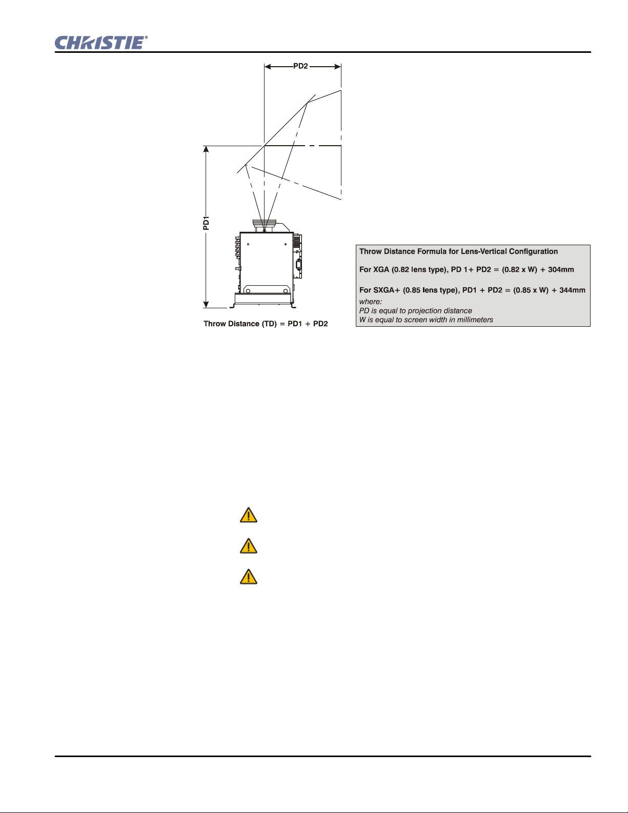
In lens-vertical configurations, where a first surface mirror is used to shorten the
distance between the projector and screen by folding the optical path, throw
distance is a little more difficult to calculate, as there are many variables to
consider.
2-6 RPMX-RPMSP-D120U & RPMSP-D275U Setup Guide
020-100038-02 Rev. 1 (09/08)
Section 2: Installation & Setup
h
Figure 2.8. Throw Distance Formula for Lens-Vertical Configuration
Lifting and transporting the projector – Use the handles in the mounting tray to
transport the projector a short distance. For longer distances, it is recommended you
use a stable cart or ask for someone’s help.
Mounting
Refer to the drawings provided for your specific projector model in Appendix D for
the mounting hole location and other technical information which may be useful
during installation.
When mounting a projector, do the following:
•
Mount the projector to a sturdy, flat surface such as a table or cart that
fits the entire projector.
•
Use all four mounting points to secure the projector to the surface. Refer
to Appendix D.
• Maintain an area of empty space around your projector, called a “stay
out zone”, to allow for proper air circulation and allow enough clearance for
cable connections to the input panel. An insufficient stay out zone area could
cause the projector to overheat during operation and/or place undue stress on
source connections.
Connect sources
Step 4
All source connections are made to the input panel of the Electronics Module. This is
the stand alone module to the left of the light engine when looking at the projector
from the back.
Each input is clearly labeled for easy identification. Using the appropriate
cable(s), connect your source. Connect RGB and YPbPr sources to
RPMX-RPMSP-D120U & RPMSP-D275U Setup Guide 2-7
020-100038-02 Rev. 1 (09/08)
INPUT 1

Section 2: Installation & Setup
h
located in the upper right corner of the input panel. Use the DVI-I connector at
INPUT 2 to connect analog or digital display signals. Connect composite video to
INPUT 3 and S-video to INPUT 4. NOTE: One of the available optional input
modules can be installed at
INPUT 5 for additional connections.
Refer to 2.4 Connecting Sources for more details on connecting a specific source.
Turn the projector ON and select a source
Step 5
WARNINGS
The North American rated line cord is provided with
this projector. For all other regions, ensure that you
are using a line cord, power plug and socket that
meet the appropriate rating standards.
Before powering ON, ensure the lamp changer lock
screw has been removed. Failure to remove this screw
can cause damage to the projector and the lamp
changer assembly.
Do not use a line cord that has been damaged.
1. Plug an approved line cord into the projector’s AC receptacle, which is
located on the electronics module. Then plug the 3-pronged end of the
line cord into a grounded AC outlet. NOTE: The outlet must be near the
equipment and easily accessible. Use only the line cord provided with the
projector or a power cord of appropriate ratings that comply with
regional standards. Do not use a line cord or AC supply not in the
specified voltage and power range. See Section 6 – Specifications for
projector power requirements.
2. Press
for two seconds to turn the projector on. As the projector
begins initialization, an active pattern of segments appear in the LED
status display window that is located with the built-in keypad. Do not
enter a keypad command until “On” appears in the status display,
otherwise the command will be ignored.
3. Press one of the input keys on the remote to select and display the image
for the source connected in Step 4. NOTE: For more information on the
keys available on the remote and their function, refer to Section 3.
NOTE: The projector enforces a 60 second wait period from the time the
projector is powered down and back up again.
2-8 RPMX-RPMSP-D120U & RPMSP-D275U Setup Guide
020-100038-02 Rev. 1 (09/08)
 Loading...