

Christie RPMX-D132U, RPMSP-D132U, RPMSP-D180U User Manual

RPMX/RPMSP-D132U
RPMSP-D180U
USER MANUAL
020-100245-03


RPMX/RPMSP-D132U
RPMSP-D180U
USER MANUAL
020-100245-03

NOTICE
This equipment has been tested and found to comply with the limits for a Class A digital device, pursuant to Part 15 of the FCC Rules. These limits are designed to provide reasonable protection against harmful interference when the equipment is operated in a commercial environment.
This equipment generates, uses, and can radiate radio frequency energy and, if not installed and used in accordance with the instruction manual,
may cause harmful interference to radio communications. Operation of this equipment in a residential area is likely to cause harmful interference
in which case the user will be required to correct the interference at his own expense.
This Class A digital apparatus complies with Canadian ICES-003.
Cet appareil numérique de la classe A est conforme à la norme NMB-003 du Canada.
이 기기는 업무용 (A 급 ) 으로 전자파적합등록을 한 기기이오니 판매자 또는 사용자는 이점을 주의하시기 바라며 , 가정 외의 지역에서 사용하는 것
을 목적으로 합니다 .
The equipment is designed and manufactured with high-quality materials and components that can be recycled and reused.
This symbol means that electrical and electronic equipment, at their end-of-life, should be disposed of separately from regular waste. Please
dispose of this equipment appropriately and according to local regulations. In the European Union, there are separate collection systems for
used electrical and electronic products. Please help us to conserve the environment we live in!
Copyright © 2008-2010 Christie Digital Systems USA, Inc. All rights reserved. All brand names and product names are trademarks, registered
trademarks or trade names of their respective holders. Canadian manufacturing facility is ISO 9001 and 14001 certified. Performance specifications are typical, but may vary depending on conditions beyond Christie's control such as maintenance of the product in proper working conditions. Performance specifications are based on information available at the time of printing. Every effort has been made to ensure accuracy,
however in some cases changes in the products or availability could occur which may not be reflected in this document. Christie reserves the
right to make changes without notice or obligation.
WARRANTY
For complete information about Christie’s limited warranty, please contact your Christie Dealer. In addition to the other limitations that may be
specified in Christie’s limited warranty, the warranty does not cover:
(a) Damage occurring during shipment, in either direction.
(b) Projector lamps (See Christie’s separate lamp program policy).
(c) Damage caused by use of a projector lamp beyond the recommended lamp life, or use of a lamp supplied by a supplier other than Christie.
(d) Problems caused by combination of the equipment with non-Christie equipment, such as distribution systems, cameras, video tape record-
ers, etc., or use of the equipment with any non-Christie interface device.
(e) Damage caused by misuse, improper power source, accident, fire, flood, lightening, earthquake or other natural disaster.
(f) Damage caused by improper installation/alignment, or by equipment modification, if by other than Christie service personnel.
(g) For LCD projectors, the warranty period specified applies only where the LCD projector is in ‘normal use. “Normal use” means the LCD pro-
jector is not used more than 8 hours a day, 5 days a week. For any LCD projector where ‘normal use” is exceeded, warranty coverage under
this warranty terminates after 6000 hours of operation.
(h) Failure due to normal wear and tear.
PREVENTATIVE MAINTENANCE
Preventative maintenance is an important part of the continued and proper operation of your projector. Please see the Maintenance section for
specified maintenance items as they relate to your projector and/or model. Failure to perform maintenance as required, and in accordance with
the maintenance schedule specified by Christie, will void the warranty.

Table of Contents
1: Introduction
1.1 Key Features ................................................................................................................................1-2
1.2 How the projector works .............................................................................................................1-3
1.3 Components .................................................................................................................................1-3
1.4 Additional Tools Required ..........................................................................................................1-3
1.5 Purchase Record and Servicing ...................................................................................................1-4
1.5.1 Purchase Record ..................................................................................................................1-4
2: Installation and Setup
2.1 Pre-Installation Considerations....................................................................................................2-1
2.1.1 Screen Size and Type........................................................................................................... 2-1
2.1.2 Ambient Lighting ................................................................................................................2-2
2.1.3 Other Considerations ...........................................................................................................2-2
2.2 Installation & Setup ....................................................................................................................2-2
2.3 Connecting Sources ..................................................................................................................... 2-11
2.4 Connecting Communications ......................................................................................................2-15
2.4.1 Remote Keypad....................................................................................................................2-15
2.4.2 Serial Port Connections .......................................................................................................2-15
2.4.3 Ethernet Communications....................................................................................................2-16
2.4.4 Connecting Multiple Projectors ........................................................................................... 2-17
2.4.5 Ethernet Network Setup.......................................................................................................2-18
2.4.6 Separating Networks............................................................................................................2-19
2.4.7 Communicating to All Ports ................................................................................................2-19
2.4.8 System Integration GPIO Connector ...................................................................................2-20
2.5 Power Connection........................................................................................................................2-20
2.5.1 Connecting the projector to AC ...........................................................................................2-20
2.5.2 Disconnecting the projector from AC.................................................................................. 2-21
3: Operation
3.1 About the Projector...................................................................................................................... 3-1
3.1.1 Projection Head Module .....................................................................................................3-1
3.1.2 6-Axis Adjuster....................................................................................................................3-1
3.1.3 Lamps and Mechanical Lamp Changer ...............................................................................3-2
3.1.4 Electronics Module (EM) ....................................................................................................3-2
3.1.5 Cooling and Air Vents .........................................................................................................3-3
3.2 Using the Remote IR Keypad......................................................................................................3-3
3.2.1 Keypad Commands..............................................................................................................3-5
3.3 Navigating the Menus.................................................................................................................. 3-10
3.4 Using Inputs and Channels ..........................................................................................................3-14
3.4.1 Selecting an Input or Channel..............................................................................................3-14
3.4.2 Creating a New Channel ......................................................................................................3-15
3.4.3 Using a Channel...................................................................................................................3-16
3.4.4 Copying or Deleting Channels.............................................................................................3-17
3.5 Adjusting the Image.....................................................................................................................3-20
3.5.1 Before You Begin ................................................................................................................3-20
RPMX/RPMSP-D132U & RPMSP-D180U User Manual i
020-100245-03 Rev. 1 (11-2010)

Table of Contents
3.6 Size and Position Menu ...............................................................................................................3-20
3.6.1 Resize Presets.......................................................................................................................3-21
3.6.2 Size.......................................................................................................................................3-23
3.6.3 Vertical Stretch ....................................................................................................................3-23
3.6.4 Pixel Track ...........................................................................................................................3-23
3.6.5 Pixel Phase ...........................................................................................................................3-24
3.6.6 H-Position ............................................................................................................................3-24
3.6.7 V-Position ............................................................................................................................3-24
3.6.8 Advanced Size and Position —Submenu.............................................................................3-24
3.7 Image Settings Menu ...................................................................................................................3-25
3.7.1 Contrast ................................................................................................................................3-26
3.7.2 Brightness.............................................................................................................................3-26
3.7.3 Gamma .................................................................................................................................3-26
3.7.4 Filter .....................................................................................................................................3-26
3.7.5 Detail....................................................................................................................................3-27
3.7.6 Noise Reduction...................................................................................................................3-27
3.7.7 Color Space ..........................................................................................................................3-27
3.7.8 Video Options — Submenu .................................................................................................3-28
3.7.9 Input Levels — Submenu ....................................................................................................3-30
3.7.10 Advanced Image Settings — Submenu ............................................................................3-32
4: Advanced Configuration and Controls
4.1 Language......................................................................................................................................4-1
4.2 Image Orientation ........................................................................................................................4-1
4.3 Fade Time ....................................................................................................................................4-1
4.4 Auto Power-up.............................................................................................................................4-1
4.5 Set Date & Time ..........................................................................................................................4-2
4.6 Menu Preferences — Submenu ...................................................................................................4-2
4.7 Communications ..........................................................................................................................4-3
4.7.1 Baud Rates ...........................................................................................................................4-3
4.7.2 Projector ...............................................................................................................................4-3
4.7.3 Network Routing..................................................................................................................4-4
4.7.4 Ethernet Settings (Submenu) ...............................................................................................4-5
4.7.5 Broadcast Key ......................................................................................................................4-6
4.7.6 Front IR Protocol .................................................................................................................4-6
4.7.7 Wired Keypad Protocol........................................................................................................4-7
4.8 Geometry and Color.....................................................................................................................4-7
4.8.1 Test Pattern ..........................................................................................................................4-7
4.8.2 Vertical Keystone.................................................................................................................4-7
4.8.3 Brightness Uniformity — Submenu ....................................................................................4-8
4.8.4 Edge Blending — SUBMENU ............................................................................................4-8
4.8.5 Color Adjustments by X/Y, and Color Saturation — Submenus ........................................4-8
4.9 Diagnostics / Calibration ............................................................................................................4-11
4.9.1 Test Pattern ..........................................................................................................................4-11
4.9.2 Gray Level............................................................................................................................4-11
4.9.3 Freeze Image ........................................................................................................................4-11
ii RPMX/RPMSP-D132U & RPMSP-D180U User Manual
020-100245-03 Rev. 1 (11-2010)

Table of Contents
4.9.4 Color Enable ........................................................................................................................4-12
4.9.5 Odd Pixel Adjustment..........................................................................................................4-12
4.9.6 Color Wheel Calibration — Submenu.................................................................................4-13
4.9.7 Peak Detector.......................................................................................................................4-13
4.9.8 Level Detector......................................................................................................................4-13
4.9.9 Level Value..........................................................................................................................4-13
4.10 Working With the Lamp............................................................................................................4-14
4.10.1 The Lamp Menu.................................................................................................................4-14
4.11 PIP and Seamless Switching......................................................................................................4-16
4.11.1 Working with PIP ..............................................................................................................4-17
4.11.2 Working with Seamless Switching ....................................................................................4-18
4.12 Status Menu ...............................................................................................................................4-20
4.13 Using Multiple Projectors..........................................................................................................4-20
4.14 Matching Colors In Multiple Screens........................................................................................4-20
4.14.1 Preliminary Calibration......................................................................................................4-20
4.14.2 Color Adjustment Procedure .............................................................................................4-21
4.14.3 Using the Color Saturation Menu for Color Matching...................................................... 4-23
4.14.4 Achieving Brightness Uniformity......................................................................................4-23
4.15 Edge Blending (SXGA Only)....................................................................................................4-27
4.15.1 Edge Blending Procedure ..................................................................................................4-29
4.16 Remote Control of the Projector................................................................................................4-30
4.17 Error Conditions ........................................................................................................................4-30
4.17.1 User Errors......................................................................................................................... 4-31
4.17.2 Input Signal Errors.............................................................................................................4-31
4.17.3 System Warnings / Errors ..................................................................................................4-32
5: Maintenance
5.1 Warnings and Safety Guidelines .................................................................................................5-1
5.1.1 Labels and Markings............................................................................................................ 5-1
5.1.2 Instructions...........................................................................................................................5-1
5.1.3 Projector Location................................................................................................................5-2
5.1.4 Lamps...................................................................................................................................5-2
5.1.5 Power Cord and Attachments ..............................................................................................5-3
5.1.6 Ventilation ...........................................................................................................................5-3
5.1.7 Servicing ..............................................................................................................................5-3
5.2 Cleaning and Maintenance Guide................................................................................................5-4
5.3 Replacing Remote Batteries ........................................................................................................5-5
5.4 Lamp Replacement ......................................................................................................................5-5
5.4.1 Replacing a lamp .................................................................................................................5-6
6: Troubleshooting
6.1 Displays .......................................................................................................................................6-1
6.2 Lamps .........................................................................................................................................6-3
6.3 Ethernet........................................................................................................................................6-3
RPMX/RPMSP-D132U & RPMSP-D180U User Manual iii
020-100245-03 Rev. 1 (11-2010)

Table of Contents
7: Specifications
7.1 Display .......................................................................................................................................7-1
7.2 Inputs ..........................................................................................................................................7-2
7.3 Power Requirements ....................................................................................................................7-4
7.4 Lamps...........................................................................................................................................7-5
7.5 Size and Weight ...........................................................................................................................7-5
7.6 Safety and EMI ............................................................................................................................7-5
7.7 Environmental..............................................................................................................................7-6
7.8 Standard Components ..................................................................................................................7-6
7.9 Optional Accessories ...................................................................................................................7-6
A: Cable Connections
A.1 Projector to Computer (RS-232).................................................................................................A-1
A.2 Projector to RS-422 compatible Computer.................................................................................A-1
A.3 Projector to Projector ..................................................................................................................A-2
B: Dimensions & Mounting Information
B.1 Horizontal Configuration ............................................................................................................B-1
B.2 Vertical Configuration ................................................................................................................B-2
B.3 Horizontal Configuration for SXGA...........................................................................................B-3
B.4 D132U Horizontal Configuration for XGA ................................................................................B-4
C: System Integration
C.1 Configuring the GPIO ...............................................................................................................C-1
C.1.1 Real Time Event..................................................................................................................C-2
D: Optional Input Modules
D.1 RGB500 Input Module 38-804606-xx........................................................................................D-1
D.2 RGB400BA Input Module 38-804610-xx ..................................................................................D-1
D.3 RGB400 Active Loop-Thru Input Module 38-804607-xx..........................................................D-2
D.4 PC250 Analog Input Module 38-804609-xx ..............................................................................D-2
D.5 DVI Input Module 38-804635-xx...............................................................................................D-2
D.6 Serial Digital Input Module 38-804602-xx.................................................................................D-3
D.7 Dual SD/HD-SDI Module 38-804856-xx ...................................................................................D-3
iv RPMX/RPMSP-D132U & RPMSP-D180U User Manual
020-100245-03 Rev. 1 (11-2010)
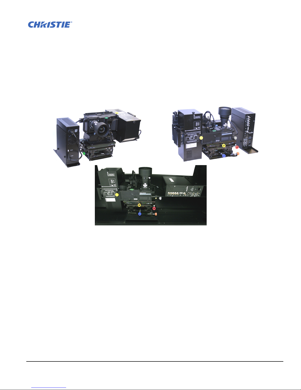
FIGURE 1-1 THE PROJECTOR
1 Introduction
RPMX/RPMSP-D132U and RPMSP-D180U are professional quality XGA and SXGA+ data projectors
featuring the latest in DLP™ display technology to achieve high brightness, high resolution multimedia and
video projection images. These projectors use Christie’s exclusive KoRE™ electronics and firmware to accept
data, graphics, and video input signals for projection onto flat, front or rear projection screens.
The modular design of these projectors makes them an ideal choice for rear screen projection and multi-display
walls. With built-in flexibility, each projector can be configured for straight throw or 90° mirrored applications.
The 6-axis adjustment mechanism enables accurate alignment of the lens to the screen minimizing distortion at
all corners and edges of the display.
A dual lamp hot swappable system allows the projector to operate with minimal downtime. The mechanical
lamp changer enables an automatic lamp change to occur when a lamp fails or whenever requested by a user.
The purpose-built design of these projectors makes them an ideal choice for the demanding needs of 24/7
command and control centers, telecommunications, surveillance and broadcasting applications.
1.1 Key Features
• RPMSP – Native SXGA+, 1400 x 1050 resolution
• RPMX – Native XGA, 1024 x 768 resolution
• 24-bit RGB display
• 10-bit image processing module
RPMX/RPMSP-D132U & RPMSP-D180U User Manual 1-1
020-100245-03 Rev. 1 (11-2010)

Section 1: Introduction
• Display of RGB, NTSC, PAL, and SECAM video inputs and HDTV formats
• User adjustable lamp power
• Mechanical lamp changer for easy lamp change during operation
• Picture-in-picture display
• Edge Blending ability via software for seamless displays (only available on SXGA+ models)
• Dual frequency IR sensor for use with standard IR remote and optional long-range dual frequency remote
• 6-axis image geometry adjustment mechanism
• Memory for up to 50 custom “channels” (source setups)
• Intuitive on-screen menu system
• Built-in GPIO port to enable active control of external devices
• LED display for projector status monitoring
• Multiple control options including RS-232, RS-422 and ethernet
• On-board ChristieNET™ software
• Universal AC input 100-240 VAC, 50/60Hz
See Section 7 Specifications for a complete list of product specifications.
1.2 How the projector works
The user selects which lamp will be in operation through the Lamp Menu; Lamp #1 or Lamp #2. After the
lamp ignites, the light generated is sequentially filtered into the RGB color primaries by the spinning color
wheel in the light engine of the projector. This filtered light is then presented to the single chip DMD, located
in the light engine. The reflected light from the DMD chip then passes through the projection lens to the screen
to display the image.
1.3 Components
Make sure you have received these components before using the projector.
• Line Cord (rated, North American)
• Configuration bracket (shipped loose, for horizontal configuration)
• 6xM6 screws (for installation of configuration bracket)
NOTE: A User’s Kit is provided with each projection system. Additional User’s Kits can be purchased
separately (part number 102-144100-XX).
1.4 Additional Tools Required
Keep these tools on hand during installation and setup:
#1 Phillips screw driver
1-2 RPMX/RPMSP-D132U & RPMSP-D180U User Manual
020-100245-03 Rev. 1 (11-2010)
1.5 Purchase Record and Servicing
Christie’s factory and dealer service network is available to diagnose and correct projector malfunctions.
Service manuals and updates are available to service technicians for all projectors.
If you encounter any problems with the projector and require assistance, contact your dealer or Christie Digital
Systems. Fill out the information in the table below and keep with your records for future reference.
1.5.1 Purchase Record
Dealer:
Dealer Phone Number:
Projector Serial Number:
Purchase Date:
Installation Date, if applicable:
Section 1: Introduction
NOTE: The serial number can be found on the license label.
To register your product on-line visit http://www.christiedigital.com/ Product Resources & Service
Product Registration. This will keep you in touch with all the latest product information, such as updates,
technical bulletins, downloads and Christie newsletters.
RPMX/RPMSP-D132U & RPMSP-D180U User Manual 1-3
020-100245-03 Rev. 1 (11-2010)


2 Installation and Setup
Use this section to install and setup your projector. Complete these steps:
Step 1 – Unpack the projector.
Step 2 – Select and modify the projector’s configuration according to the intended application: lens-vertical
(90 degree) or lens-horizontal (0 degree) projection.
Step 3 – Calculate throw distance if necessary. Position and mount the projector.
Step 4 – Connect sources.
Step 5 – Turn the projector on.
Step 6 – Adjust projection lens to improve image focus.
Step 7 – Adjust image geometry using the 6-axis adjuster.
Step 8 – Adjust software to optimize image on a single screen, or multiple screens.
NOTES: 1) The illustrations used in this manual are graphical representations only and may not depict your
projector model exactly.
2) If you are installing your projector in a TotalVIEW™ 50” or 67” cube enclosure, refer to the separate
installation guide provided (020-100248-XX).
2.1 Pre-Installation Considerations
Whether installing your projector permanently or temporarily take the following into account to get the best
possible performance from your projector. When designing a projection room consider:
• are you operating single or multiple units
• the room size
• lighting and audience seating
• distance the audience is sitting from the display
• from which angle the display is viewed
These are important when deciding where to place the display, or what type and size of screen to use.
2.1.1 Screen Size and Type
Choose an appropriate screen size for your lens and application. If the projector is displaying text information,
the image size must be large enough to allow the audience to view all text clearly. The eye-to-text distance
should be less than 150 times the height of the letter. Small text located too far from the eye will be illegible at
a distance no matter how sharply and clearly it is displayed.
To fill a screen with an image, the aspect ratio (expressed as the ratio of its width to its height) of the screen
must be equal to the aspect ratio of the image. Screens with an aspect ratio of 4:3 are recommended for use
with these projectors.
Diffused and optical screens are best suited for rear screen installations. A diffused screen has a surface which
spreads the light striking it. Purely diffused screens have a gain of less than 1. Optical screens take light from
the projector and redirect it to increase the light intensity at the front of the screen.
RPMX/RPMSP-D132U & RPMSP-D180U User Manual 2-1
020-100245-03 Rev. 1 (11-2010)

Section 2: Installation and Setup
2.1.2 Ambient Lighting
The high brightness of this projector is well suited for locations where ambient lighting might be considered
less than ideal for projection. A typical room with ceiling lights and windows rarely requires special attention.
If light directly strikes the screen, such as when a shaft of light from a window or floodlight falls on the image,
the contrast ratio in your image will be noticeably reduced and may appear washed out and less vibrant.
In general, avoid or eliminate light sources directed at the screen.
2.1.3 Other Considerations
Other considerations and tips that can help improve your installation:
• Ventilation is important, the constant ambient temperature must below 35°C (95°F). Keep the projector away
from heating and/or air conditioning vents. Changes in temperature can affect the operation of the projector
which may affect performance.
• Keep the projector away from devices radiating electromagnetic energy such as motors and transformers,
slide projectors, speakers, power amplifiers, elevators, etc.
• Use an optical mirror for rear screen installations to shorten the optical light path and use less space in the
projection room.
• When designing a projection room, consider positioning the projector and screen for maximum audience
coverage and space efficiency. For example, placing the screen along the larger wall in a rectangular room
reduces audience coverage.
2.2 Installation & Setup
This section outlines the installation sequence of an RPMX/RPMSP-D132U or RPMSP-D180U projector as a
stand alone or multiple projector installation.
For instructions on how to install your projector into the TotalVIEW™ 50” or 67” cube enclosure, refer to the
separate Cube Installation Manual (020-100248-XX) provided in the User’s Kit.
Step 1 Unpacking the projector
The projector is shipped fully assembled in the lens-vertical (90 degree) configuration. After receiving your
projector it is important that you prepare it for installation by:
Removing the projector from the box and discarding any packing material surrounding the modules.
2-2 RPMX/RPMSP-D132U & RPMSP-D180U User Manual
020-100245-03 Rev. 1 (11-2010)
Section 2: Installation and Setup
AC
AC
DVI OUT
DVI IN
A
A
B
B
PWR
PWR
IR
Overhead View
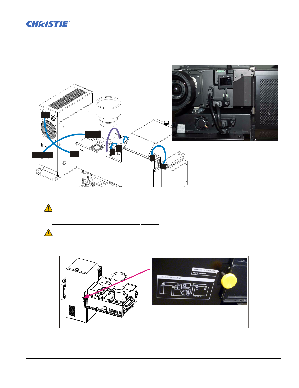
FIGURE 2-1 INTERNAL CABLE CONNECTIONS
FIGURE 2-2 REMOVE LAMP CHANGER LOCK SCREW
NOTE: An L-shaped bracket, used to change the projector’s configuration, is shipped loosely in the box with
the projector. Set this aside for future use.
Verifying all cable connections are secure. Connect any loose cables. See Figure 2-1 Internal Cable
Connections.
Remove the lock screw located on the mechanical lamp changer. See Figure 2-2 Remove Lamp Changer
Lock Screw. This screw is used for shipping purposes only and must be removed prior to turning the projector
on. Failure to do so can result in projector
damage.
Check lamp handles. These handles must lay flat against the lamp surface otherwise they will interfere
with lamp operation.
RPMX/RPMSP-D132U & RPMSP-D180U User Manual 2-3
020-100245-03 Rev. 1 (11-2010)
Section 2: Installation and Setup
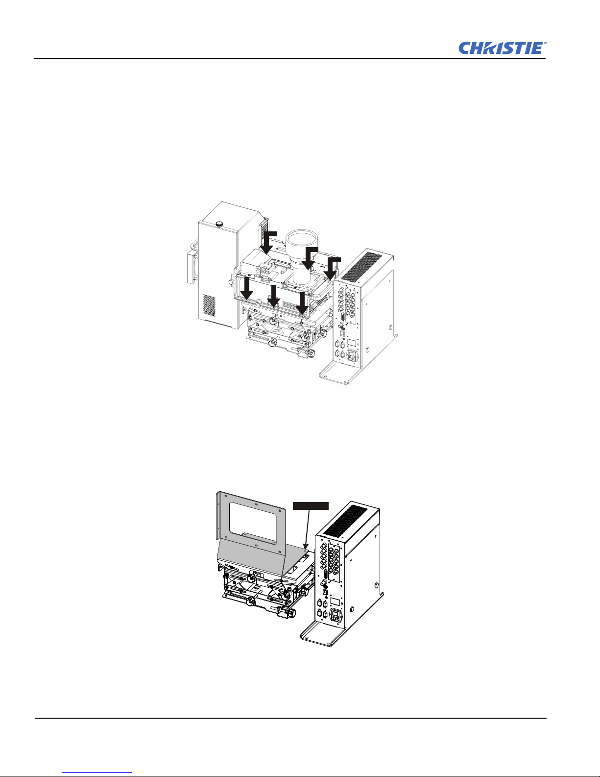
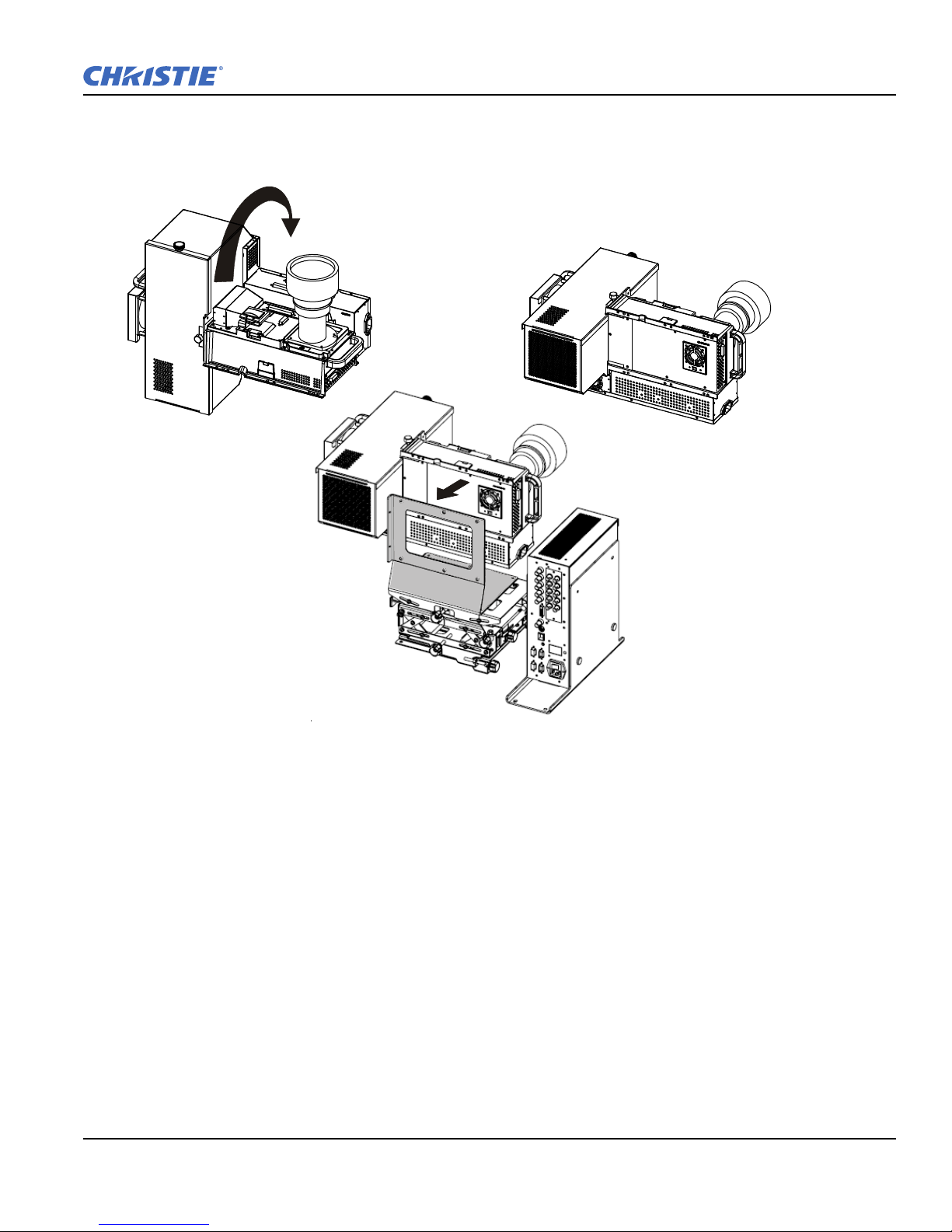
FIGURE 2-3 LOOSEN LIGHT ENGINE
6 screws
FIGURE 2-4 INSTALL CONFIGURATION BRACKET TO ADJUSTER BASE
Step 2 Modifying projector configuration (if required)
To use your projector for lens-horizontal projection then you must change its configuration. The L-shaped
bracket and M6 screws shipped with the projector are needed to complete this configuration change.
1. Unplug projector from AC.
2. Disconnect all cables between the light engine and electronics module. All disconnects must be made on
the light engine side.
3. Remove the (6) M4 screws securing the light engine module to the 6-axis adjuster, see Figure 2-3 Loosen
Light Engine.
4. Lift the light engine off the adjuster and set aside.
5. Align the shorter end of the L-shaped bracket with the mounting holes in the adjuster base, as shown in
Figure 2-4 Install configuration bracket to adjuster base.
6. Secure the bracket to the adjuster base with the (6) M4 screws used to secure the light engine.
2-4 RPMX/RPMSP-D132U & RPMSP-D180U User Manual
020-100245-03 Rev. 1 (11-2010)
Section 2: Installation and Setup
90°
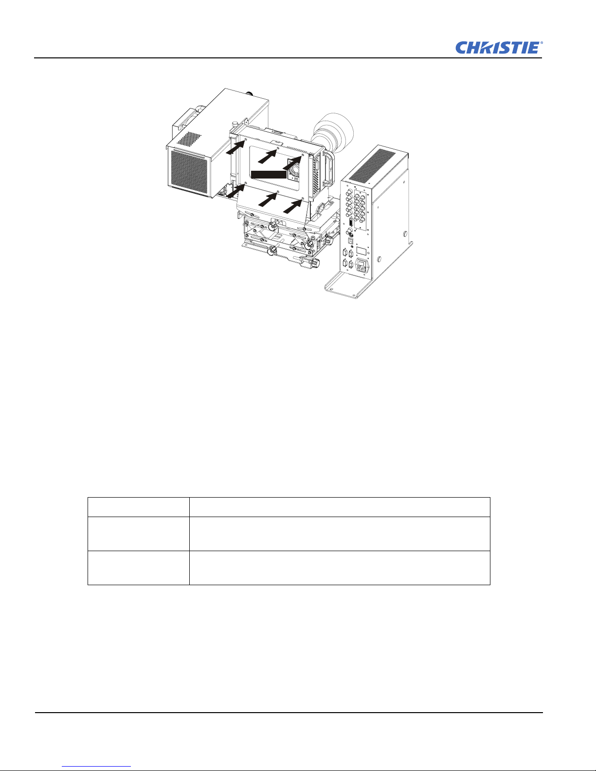
FIGURE 2-5 RE-POSITION LIGHT ENGINE
7. Place the light engine in the lens-horizontal position on the L-shaped bracket and adjuster base. Align the
mounting holes between the configuration bracket and light engine and secure using the (6) additional M6
screws provided with the projector.
RPMX/RPMSP-D132U & RPMSP-D180U User Manual 2-5
020-100245-03 Rev. 1 (11-2010)
Section 2: Installation and Setup
6 screws
FIGURE 2-6 SECURE LIGHT ENGINE TO CONFIGURATION
8. Reconnect all cables disconnected previously in step 2. Refer to Figure 2-1 Internal Cable Connections.
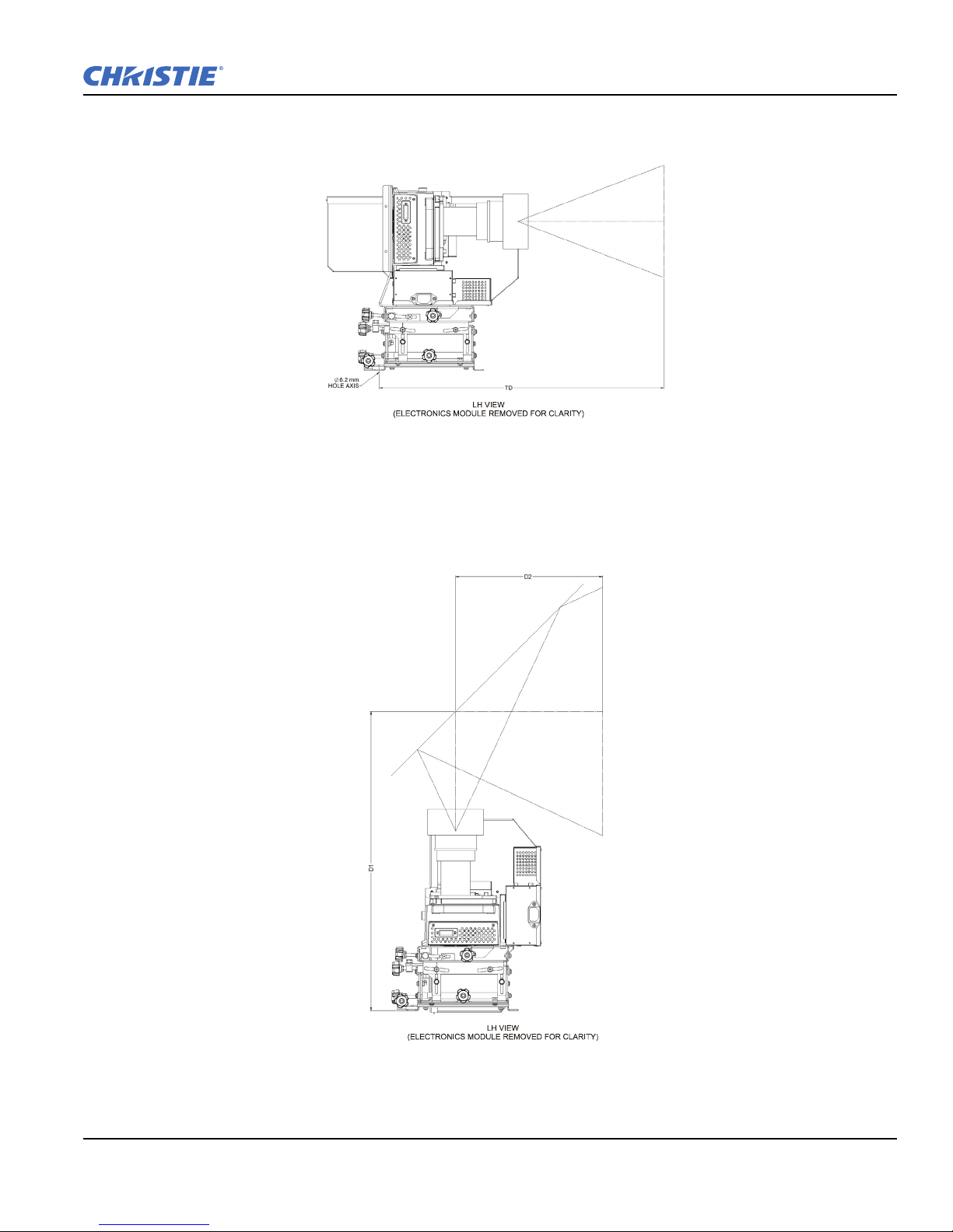
Step 3 Calculating throw distance, position and mount projector
Throw Distance
For lens-horizontal configurations, throw distance is measured from the center of the auxiliary mounting holes
in the tray to the screen. Use the appropriate formula for your projector model when calculating.
In both vertical and horizontal configurations:
TD = Throw Distance
W = screen width in millimeters
RPMX-D132U For XGA (0.69:1 lens). TD = 0.69 x W +54 mm
RPMSP-D132U
RPMSP-D180U
For SXGA+ (0.69:1 lens). TD = 0.69 x w +54 mm
For SXGA+ (1.20:1 lens). TD = 1.2 x W + 29 mm
For SXGA+ (0.69:1 lens). TD = 0.69 x W + 33 mm
For SXGA+ (1.20:1 lens). TD = 1.2 x W + 29 mm
See Figure 2-7 Throw Distance Formula for Lens-Horizontal Configuration for an illustration of the formula.
2-6 RPMX/RPMSP-D132U & RPMSP-D180U User Manual
020-100245-03 Rev. 1 (11-2010)
Section 2: Installation and Setup
FIGURE 2-7 THROW DISTANCE FORMULA FOR LENS-HORIZONTAL CONFIGURATION
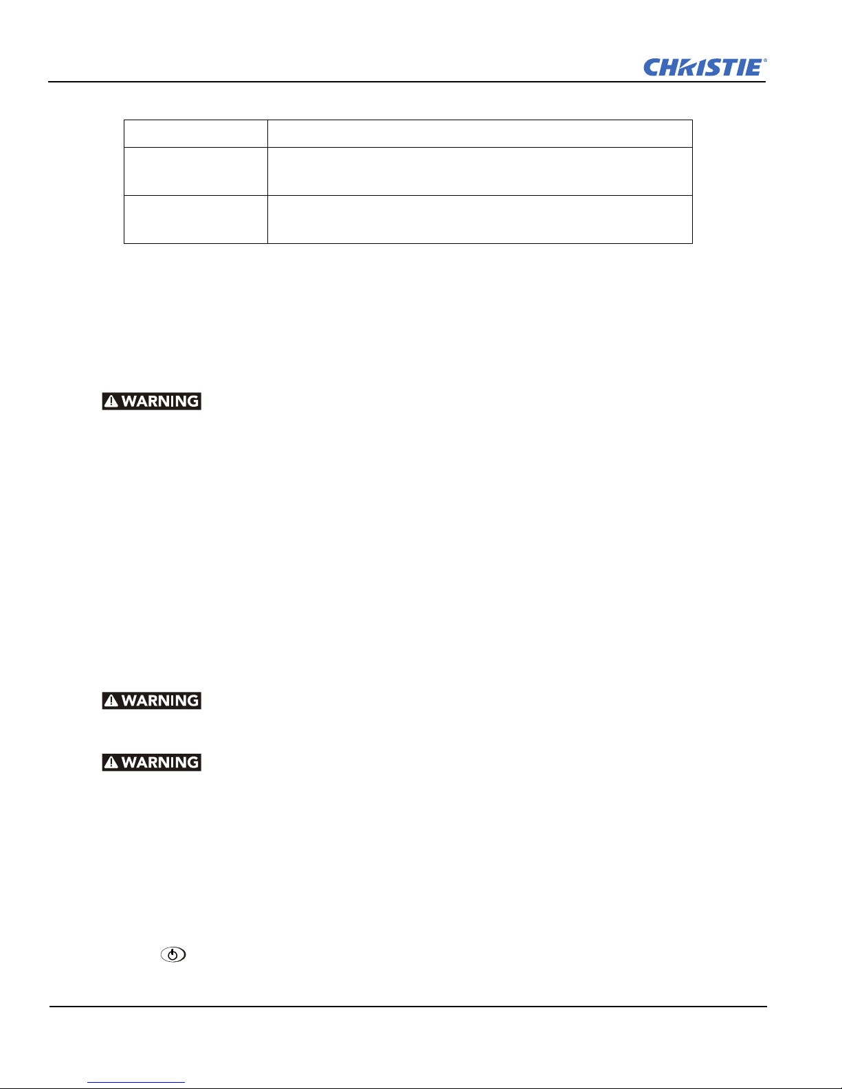
FIGURE 2-8 THROW DISTANCE FORMULA FOR LENS-VERTICAL CONFIGURATION
For lens-vertical configurations, where a first surface mirror is used to shorten the distance between the
projector and screen by folding the optical path, throw distance is a little more difficult to calculate, as there are
many variables to consider.
RPMX/RPMSP-D132U & RPMSP-D180U User Manual 2-7
020-100245-03 Rev. 1 (11-2010)
Section 2: Installation and Setup
RPMX-D132U For XGA (0.69:1 lens). TD = 0.69 x W + 336 mm
RPMSP-D132U
RPMSP-D180U
For SXGA+ (0.69:1 lens). TD = 0.69 x W + 336 mm
For SXGA+ (1.20:1 lens). TD = 1.2 x W + 311 mm
For SXGA+ (0.69:1 lens). TD = 0.69 x W + 336 mm
For SXGA+ (1.20:1 lens). TD = 1.2 x W + 311 mm
Lifting and transporting the projector
Use the handles on either side of the light engine to lift the projector. Use a stable cart to transport the projector.
Mounting
Refer to the drawings provided for your specific projector model in Appendix Section B Dimensions &
Mounting Information for mounting hole locations and other technical information.
Mount the projector to a sturdy, flat surface that fits the entire projector.
Use all four mounting points to secure the projector to the surface. Refer to
Appendix Section B
Dimensions & Mounting Information.
Maintain an area of empty space around the projector, called a “stay out zone”, to allow for air
circulation and clearance for cable connections to the input panel. An insufficient stay out zone area can
cause the projector to overheat during operation and/or place undue stress on source connections.
Step 4 Connecting sources
All source connections are made to the input panel of the Electronics Module. Each input is labeled for easy
identification. Using the appropriate cables, connect your source. Refer to Section 2.3 Connecting Sources for
more details on connecting a specific source.
NOTE: An optional input module can be installed at Input 5 if additional connections are required. Refer to
Appendix D Optional Input Modules.
Step 5 Turning the projector on and selecting a source
A North American rated line cord is provided with this projector. For all other regions,
make sure that you are using a line cord, power plug and socket that meet the applicable rating
standards.
Do not use a damaged line cord.
Before powering on make sure the lamp changer lock screw is removed. Failure to remove this screw
can cause damage to the projector and the lamp changer assembly.
1. Plug an approved line cord into the projector’s AC receptacle, located on the electronics module. Plug the
3-pronged end of the line cord into a grounded AC outlet.
NOTE: The outlet must be near the equipment and easily accessible. Use only the line cord provided with the
projector or a power cord of appropriate rating that complies with regional standards.
NOTE: Do not use a line cord or AC supply not in the specified voltage and power range. See section Section
7 Specifications for projector power requirements.
2. Press for two seconds to turn the projector on. As the projector begins initialization, an active pattern
of segments appears in the LED status display window. Commands will be ignored until “On” appears.
2-8 RPMX/RPMSP-D132U & RPMSP-D180U User Manual
020-100245-03 Rev. 1 (11-2010)
Section 2: Installation and Setup
3. Press one of the input keys on the remote to select and display the image for the source connected in Step
4.
NOTE: For more information on the keys available on the remote and their function, refer to Section Section 3
Operation.
NOTE: To protect the lamp, the projector enforces a 60 second wait period from the time the projector is
powered down and back up again.
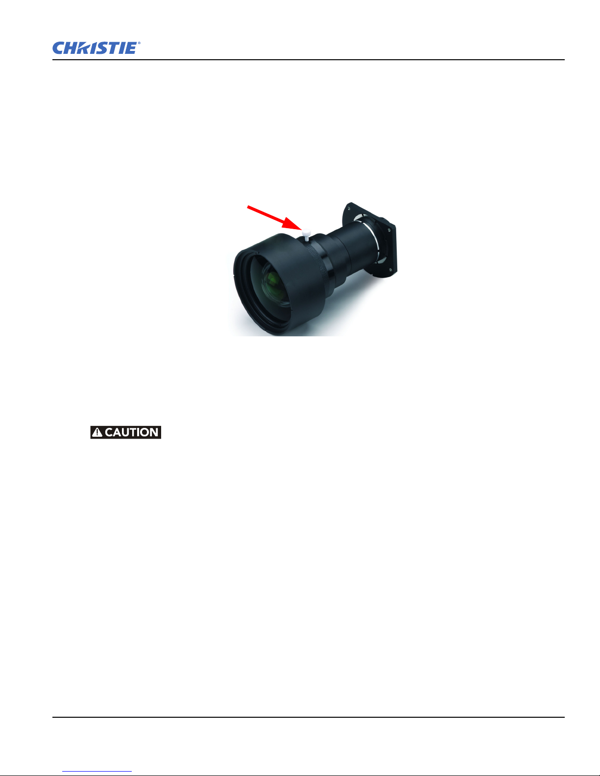
Step 6 Adjusting the projection lens
FIGURE 2-9 XGA LENS ADJUSTMENT
1. Loosen the adjustment handle (turn thumb wheel) on the lens barrel.
2. When the image is focused, lock adjustments in place by tightening the adjustment handle until just tight.
Lock lens adjustments to prevent unnecessary tampering.
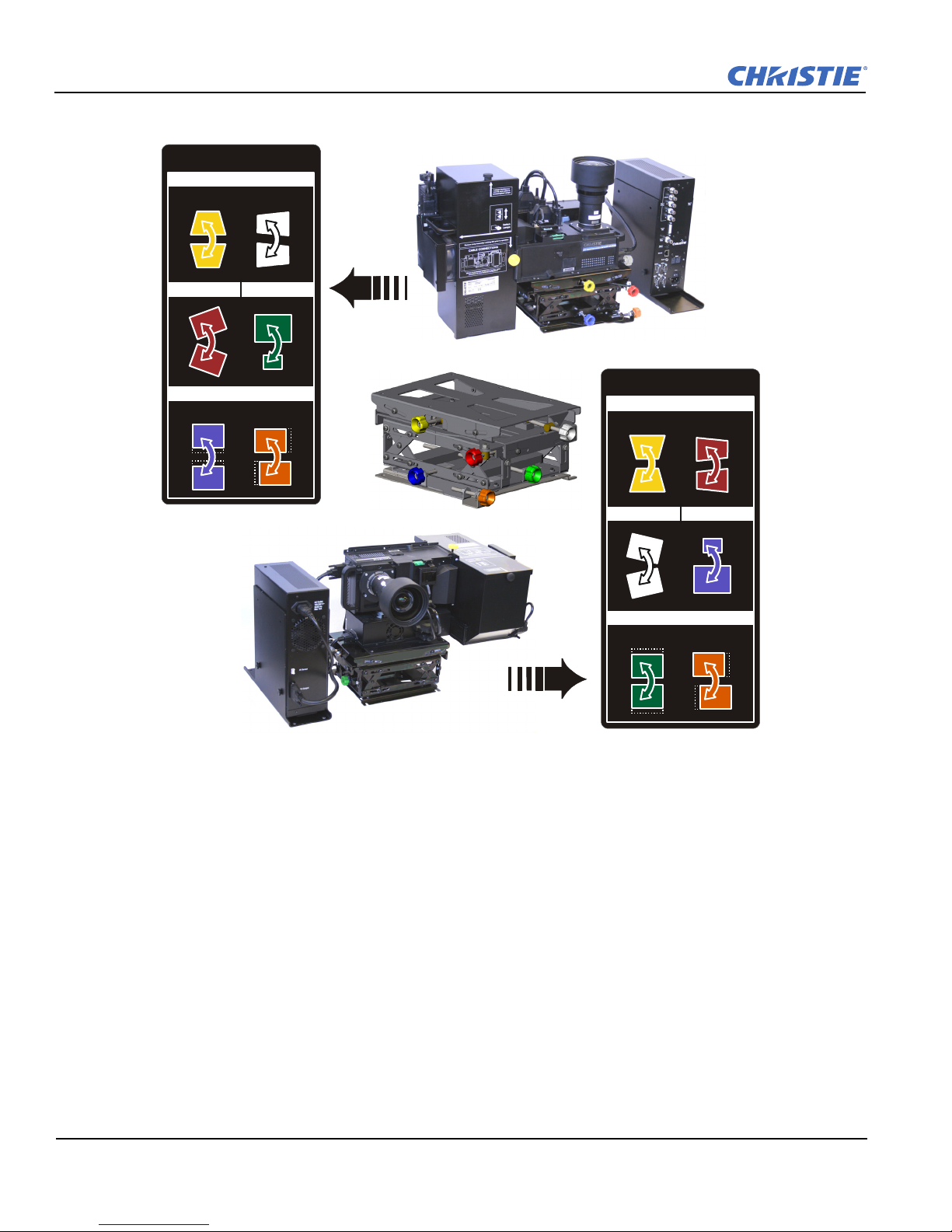
Step 7 Adjusting image geometry using the 6-axis adjuster
The light engine is mounted to the 6-axis adjuster mechanism which can fine-tune the geometry of a displayed
image by moving and rotating the light engine about the X, Y and Z axes.
For single projectors, adjust the 6-axis adjuster until the displayed image fills the screen and appears without
geometric distortion.
For a multi-projector display wall, use the 6-axis adjuster to closely match the image across multiple screens.
Start in the center of the bottom row and work out and up.
To adjust the 6-axis adjuster:
1. Center the image on screen, by adjusting vertical and/or horizontal position.
2. Zoom the image out (make smaller) until it fits within the borders of the screen.
3. Adjust keystone and tilt.
4. Zoom the image in (make larger) to fill the screen.
5. Repeat above until the image appears correctly.
RPMX/RPMSP-D132U & RPMSP-D180U User Manual 2-9
020-100245-03 Rev. 1 (11-2010)
Section 2: Installation and Setup
Vert ica l Hor izo nta l
Vert ica l Hor izo nta l
6-AXIS ADJUSTMENT
KEYSTONE
TILT ZOOM
POSITION
Vert ica l
Horizontal
Vert ica l
Horizontal
6-AXIS ADJUSTMENT
KEYSTONE
TILT ZOOM
POSITION
FIGURE 2-10 6-AXIS ADJUSTMENTS
Step 8 Adjust software to optimize image
NOTES: 1) Refer to Section 3 Operation for details on accessing and adjusting individual settings.
2) Unless otherwise indicated, instructions apply to all projector models in stand-alone or multi-projector
configurations.
1. Display an external signal.
2. Select a lamp operation mode. Perform all setups in the mode you select.
3. Select Image Orientation in the Configuration menu and change the orientation of the displayed image to
4. Assign projector ID number(s).
5. Modify options in Menu Preference to suit your display preferences. For example, select Language to
suit the installation.
change the menu language to any of the available languages.
2-10 RPMX/RPMSP-D132U & RPMSP-D180U User Manual
020-100245-03 Rev. 1 (11-2010)

Section 2: Installation and Setup
6. Enable Broadcast Key in the Communications menu – this enables you to switch between communicat-
ing with one or all projectors when connected serially.
7. Select Auto Setup to allow the projector to choose the best possible settings for the selected input signal.
8. Change Resize Presets if you want the image displayed at any other resolution than native.
9. Adjust Pixel Phase and Pixel Tracking from the Size and Position menu to eliminate any noise from the
displayed image.
10. Adjust H-Position and V-Position from the Size and Position menu to re-center the image on screen.
11. Adjust Size in Size and Position until the image is at the desired width then adjust Vertical Stretch.
Adjusting one option may have an affect on the other, repeat adjustment if necessary. Adjust H-Position
and V-Positi on again if required to center the image.
12. Adjust Color Wheel Delay if necessary. See Section 4.9.6 Color Wheel Calibration — Submenu.
13. Perform Color Temperature setup.
14. Adjust Black levels and Input Levels.
15. Adjust Lamp Power to match lamp brightness of adjacent projectors, if necessary.
16. Adjust color primaries, brightness uniformity and edge blending using the detailed procedure provided in
Section Section 3 Operation– Matching Colors in Multiple Projectors.
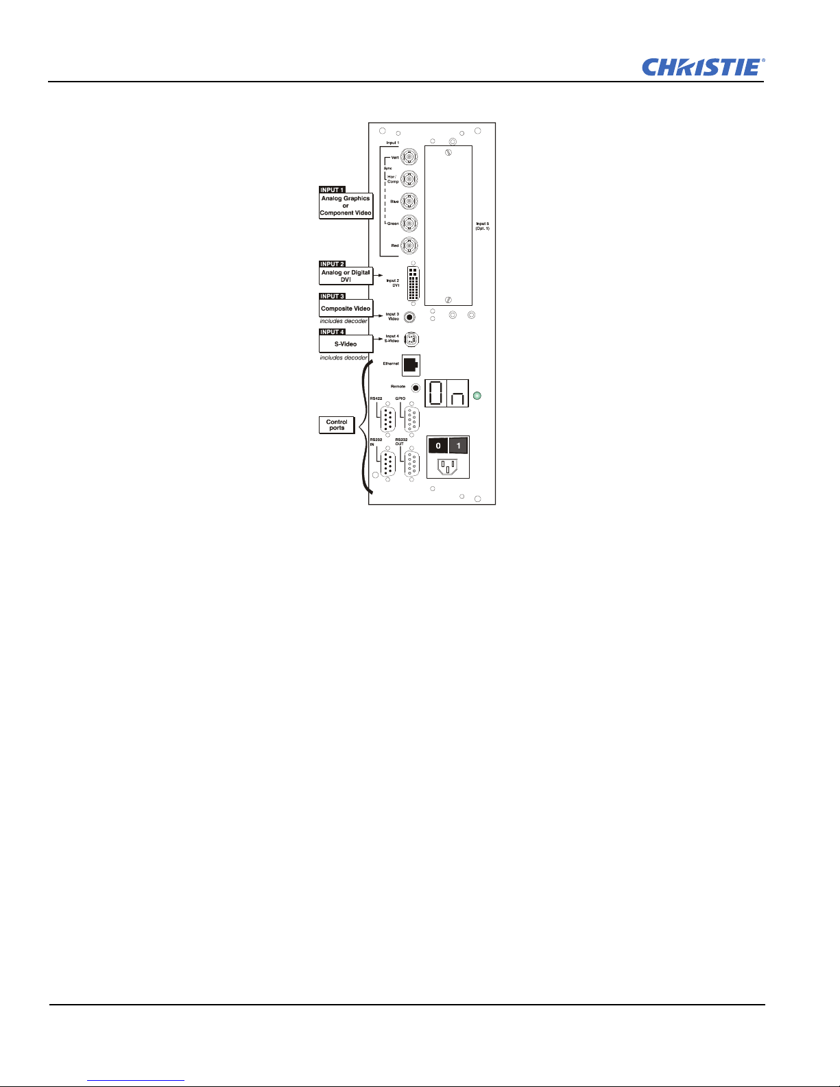
2.3 Connecting Sources
Sources connect to the Input Panel located at the back of Electronics Module.
INPUT 1 typically accepts an RGB signal from an external analog RGB source, or it can be used for YPbPr
signals or additional video sources.
analog composite video at
DVD players.
Christie offers optional input modules that can be installed into the projector at
sources. Refer to Appendix Section D Optional Input Modules.
NOTES:
1) See Section Section 7 Specifications for details regarding compatible inputs.
2) Use only high quality shielded cables for all connections.
INPUT 3 or S-video at INPUT 4 from devices such as VCRs, laser disk players or
INPUT 2 accepts digital or analog display signals from a computer. Connect
INPUT 5 to connect other
RPMX/RPMSP-D132U & RPMSP-D180U User Manual 2-11
020-100245-03 Rev. 1 (11-2010)
Section 2: Installation and Setup
FIGURE 2-11 INPUT PANEL
RGB signals (5 BNCs)
INPUT 1 has 5 BNCs for connecting a variety of sources. A typical connection would be to an RGB source such
as a PC, Mac, Sun, SGI and others. This projector supports multiple sync types: sync-on-green, composite
sync, and separate H & V syncs.
Connect the
them. Then connect the red, green and blue source outputs to the
SYNC BNC input(s). H & V syncs may be connected in any order, the projector will auto detect
RED, GREEN, and BLUE BNCs. If the source
uses sync-on-green, only the red, green, and blue connections are required. If the source provides a composite
sync output, connect it to the
vertical sync outputs, connect horizontal sync to the
to
SYNC input labeled VERT. See Figure 2-12.
SYNC input labeled HOR/COMP. If the source provides separate horizontal and
SYNC input labeled HOR/COMP and connect vertical sync
NOTES:1)Depending on the source, you may need a custom adapter cable with BNC connectors at the
projector end and a different type of connector at the other (such as a 15-pin "D" connector for some computer
sources). Contact your dealer for details.
2) If the projector fails to recognize a signal as an RGB signal, specify the Color Space option within the Image
Settings menu. See 3.5 Adjusting the Image.
3) To connect YPbPr signals–such as from DVDs or analog HDTV sources–to INPUT 1, use the red, green and
blue BNCs as described in YPbPr Signals (below).
2-12 RPMX/RPMSP-D132U & RPMSP-D180U User Manual
020-100245-03 Rev. 1 (11-2010)
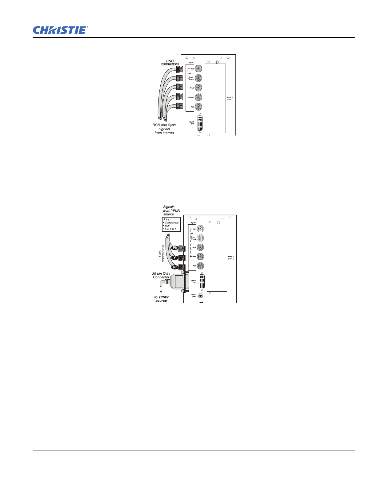
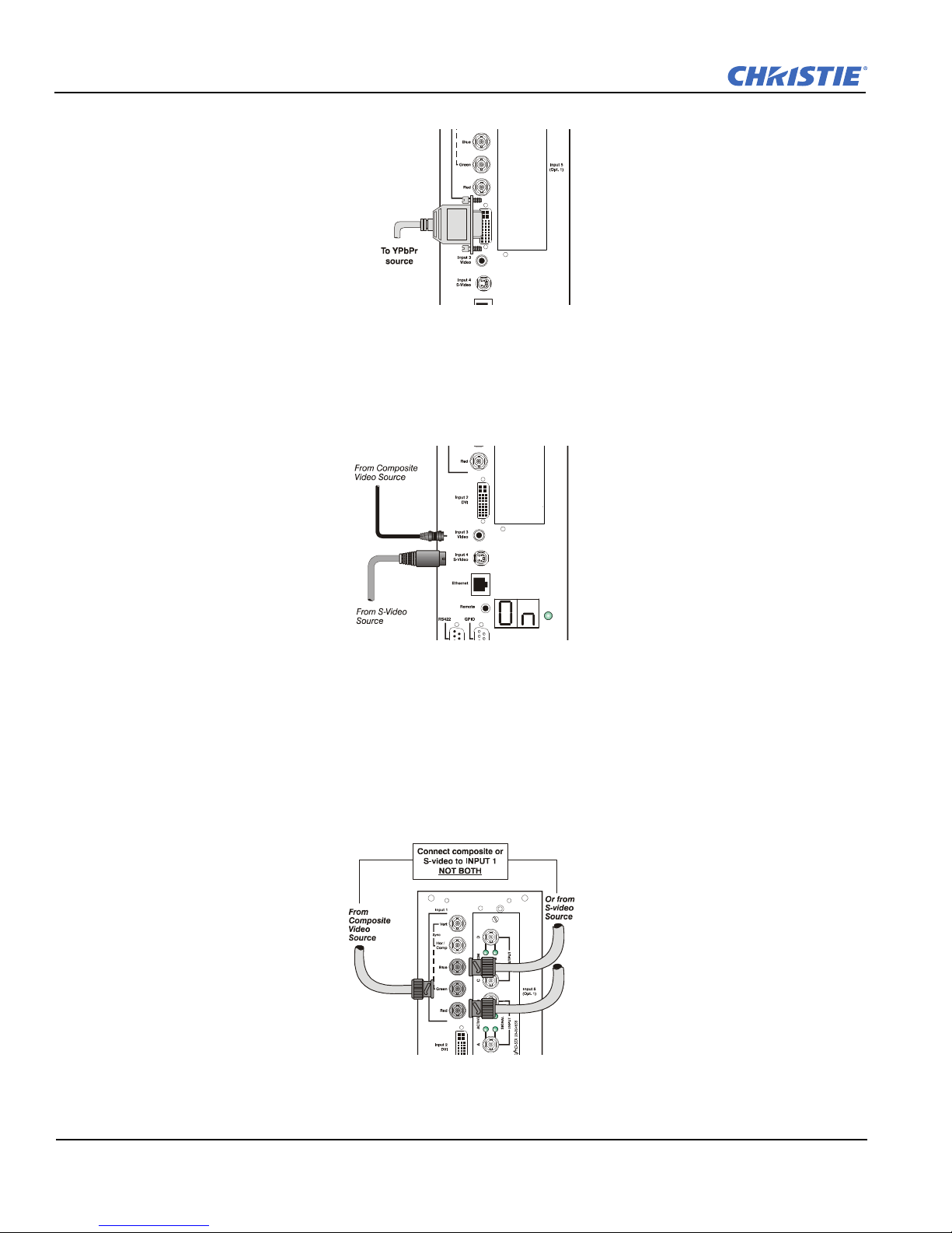
YPbPr signals
Section 2: Installation and Setup
FIGURE 2-12 CONNECTING RGB
Connect a YPbPr signal (component video) to
INPUT 1 or INPUT 2 as shown in figure 2.14.
NOTES: 1) If the projector fails to recognize a YPbPr signal, specify the Color Space option within the Image
Settings menu. See 3.5 Adjusting the Image.
FIGURE 2-13 CONNECTING YPBPR
DVI Digital Video
Use the DVI-I connector at
cable with DVI-I connectors at both ends to connect devices that transmit digital and analog video signals such
as high-quality DVD players, satellite receiver and digital cable TVs.
NOTES: 1) To make sure of true digital output from devices that transmit digital signals, connect to the DVI-I
connector.
2) DVI loop through is not available unless you have the optional DVI Input Module installed at Input 5.
RPMX/RPMSP-D132U & RPMSP-D180U User Manual 2-13
020-100245-03 Rev. 1 (11-2010)
INPUT 2 to connect either analog or digital video devices to the projector. Use a
Section 2: Installation and Setup
FIGURE 2-14 CONNECTING ANALOG OR DIGITAL VIDEO DEVICES
Composite and S-Video
INPUT 3 and INPUT 4 provide simultaneous connection of both a composite video source (INPUT 3) and an S-
Video source (
INPUT 4).
FIGURE 2-15 CONNECTING COMPOSITE / S-VIDEO
Extra Video
To use an extra video source in addition to the video source(s) connected at input 3 or input 4, connect either a
Composite or S-video source to input 1 as shown.
NOTES: 1) Do not simultaneously connect composite and s-video to input 1.
2) You can switch between video sources connected at input 1 and input 3 or input 4.
FIGURE 2-16 CONNECTING EXTRA VIDEO
2-14 RPMX/RPMSP-D132U & RPMSP-D180U User Manual
020-100245-03 Rev. 1 (11-2010)
Optional Inputs
FIGURE 2-17 CONNECTING RS-232
Optional input modules allow you to increase your total number of inputs to accommodate different signal
types, whether analog or digital. Install in the area labeled
• RGB 500 Input Module
• RGB 400 Active Loop Thru Input Module
• RGB 400 Buffered Amplifier Input Module
• PC250 Analog Input Module
• Serial Digital Input Module
• DVI Input Module
• Dual SD/HD-SDI Module
NOTE: See Appendix D Optional Input Modules for a brief description of each interface.
2.4 Connecting Communications
As an alternative to the projector’s keypad or remote, communicate with the projector using a PC or other
controller. Commands and feedback are sent via serial links (RS-232 and RS-422) and Ethernet or GPIO
communications to the projector.
Section 2: Installation and Setup
INPUT 5. Options include:
2.4.1 Remote Keypad
Direct the projector’s IR remote keypad towards the display screen or the projector’s IR sensor. Alternatively,
connect a wired (tethered) version of the remote to the RCA jack labeled
panel. Response to a wired keypad must be enabled in the Communications menu—see 3.6, Adjusting System
Parameters and Advanced Controls for more information.
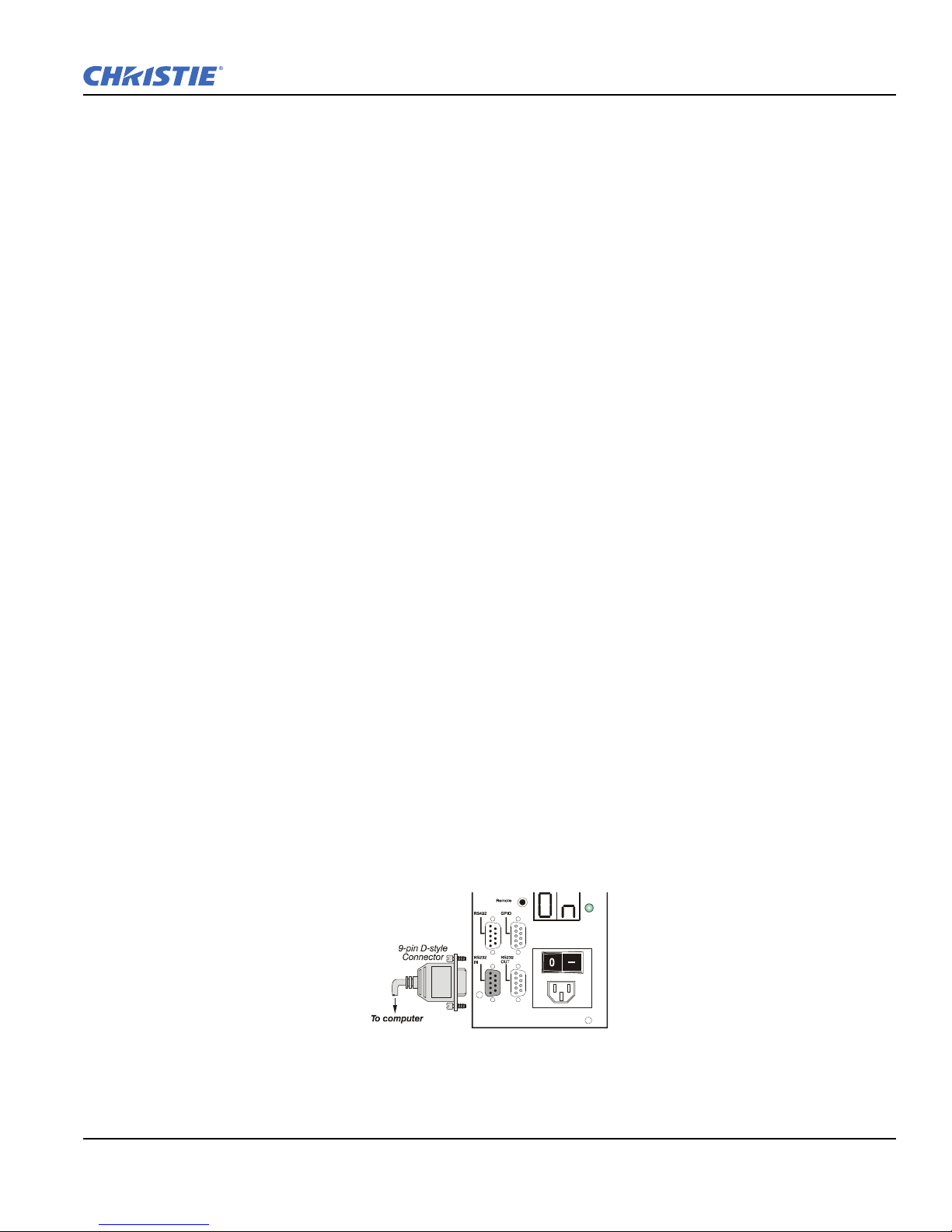
2.4.2 Serial Port Connections
RS-232 and RS-422 are the serial ports available on the projector. Connect a device with a serial interface,
such as a computer to either of these connectors (not both) and control the projector remotely by entering
specific serial communication commands.
Connecting RS-232
The two 9-pin connectors labeled RS-232 IN and RS-232 OUT on the input panel are dedicated to serial
communication. Using the appropriate serial communication cables connect the controlling source, such as a
personal computer to the RS-232 IN connector. Set the baud rate to match that of the computer. Refer to
Section 3 Operation for details on changing the projector’s baud rate.
REMOTE on the projector’s input
RPMX/RPMSP-D132U & RPMSP-D180U User Manual 2-15
020-100245-03 Rev. 1 (11-2010)
Section 2: Installation and Setup
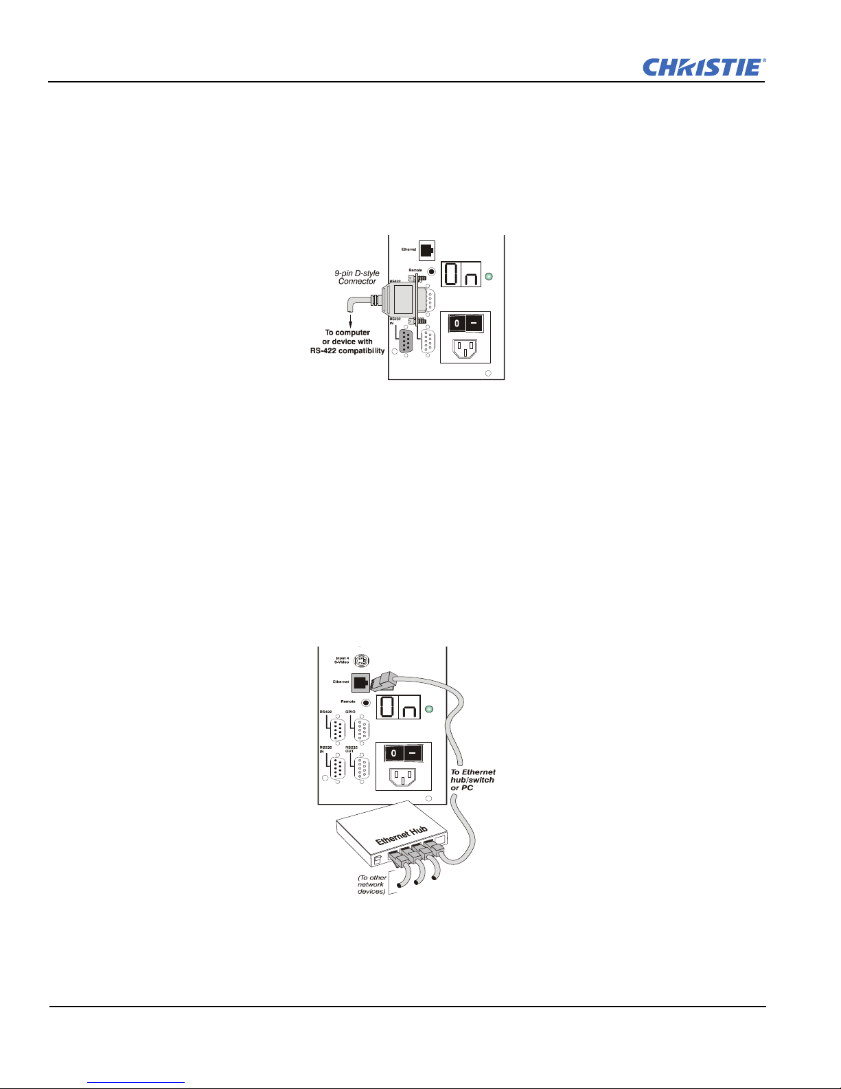
Connecting RS-422
To control the projector with a computer or other devices with RS-422 capability, connect an RS-422 serial
communication cable between the computer and the RS-422 port on the projector. RS-422 is better suited for
serial communication over long distances than RS-232 communication.
Use the RS-422 port only if your device has RS-422 capability. Consult the literature provided with your
equipment before connecting. Connecting to the RS-422 port with incompatible equipment could damage your
projector.
2.4.3 Ethernet Communications
To add the projector to an existing Ethernet network, connect standard CAT5 Ethernet cable between your
Ethernet hardware and the Ethernet port on the side of the projector.
The project factory default is DHCP enabled, an IP address will be ob ta i ed automatically. If there is no
DHCP server available on the network or if a static IP address for the projector is required, set the address in
the Ethernet Settings menu or via serial command.
FIGURE 2-18 CONNECTING RS-422
Regardless of how it is assigned, once a projector has a valid and unique address it will respond to commands
sent to this address. To determine the projector’s current IP address, consult the Status or Communications
menus.
Refer to Section 3 for further information about setting up and using a projector connected via Ethernet.
FIGURE 2-19 ETHERNET COMMUNICATION
2-16 RPMX/RPMSP-D132U & RPMSP-D180U User Manual
020-100245-03 Rev. 1 (11-2010)
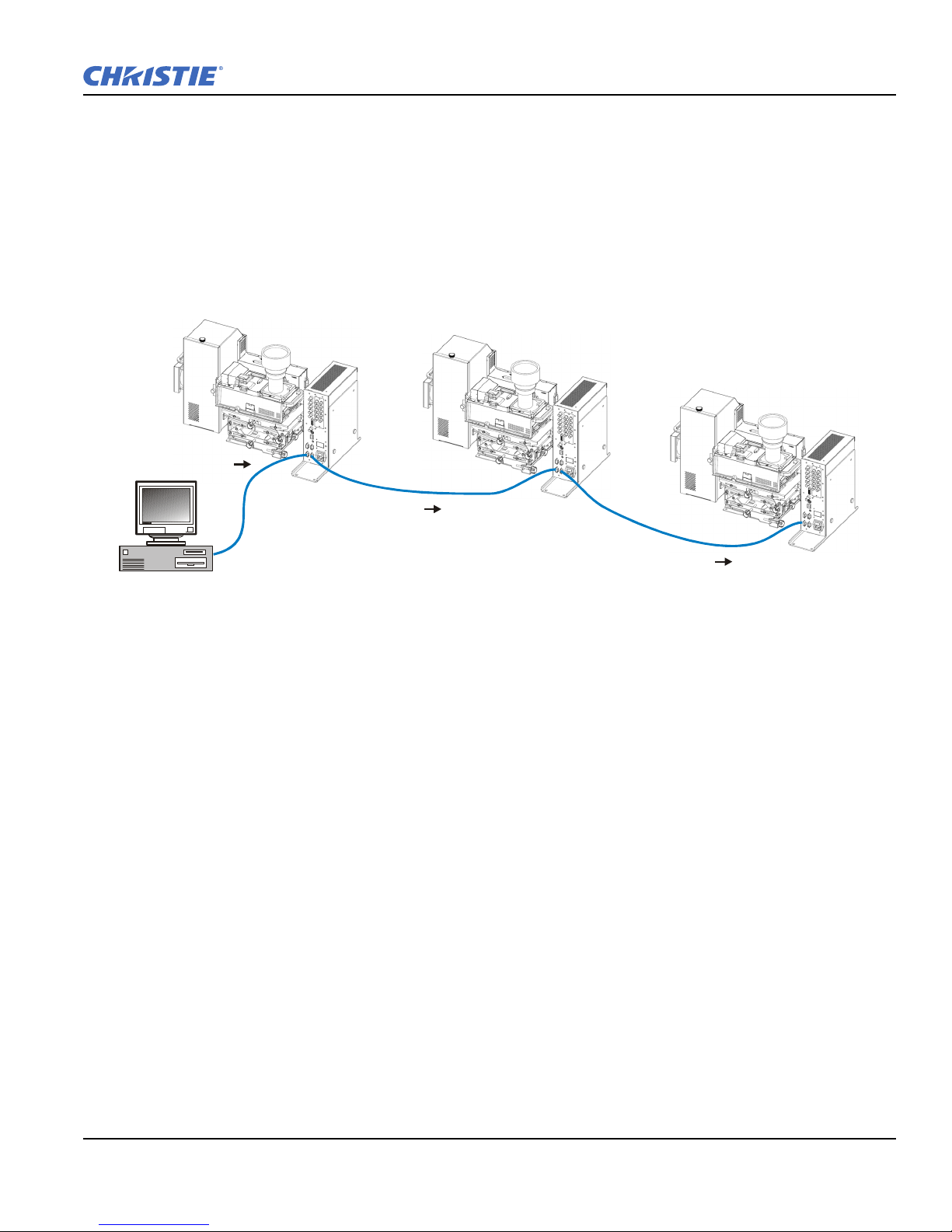
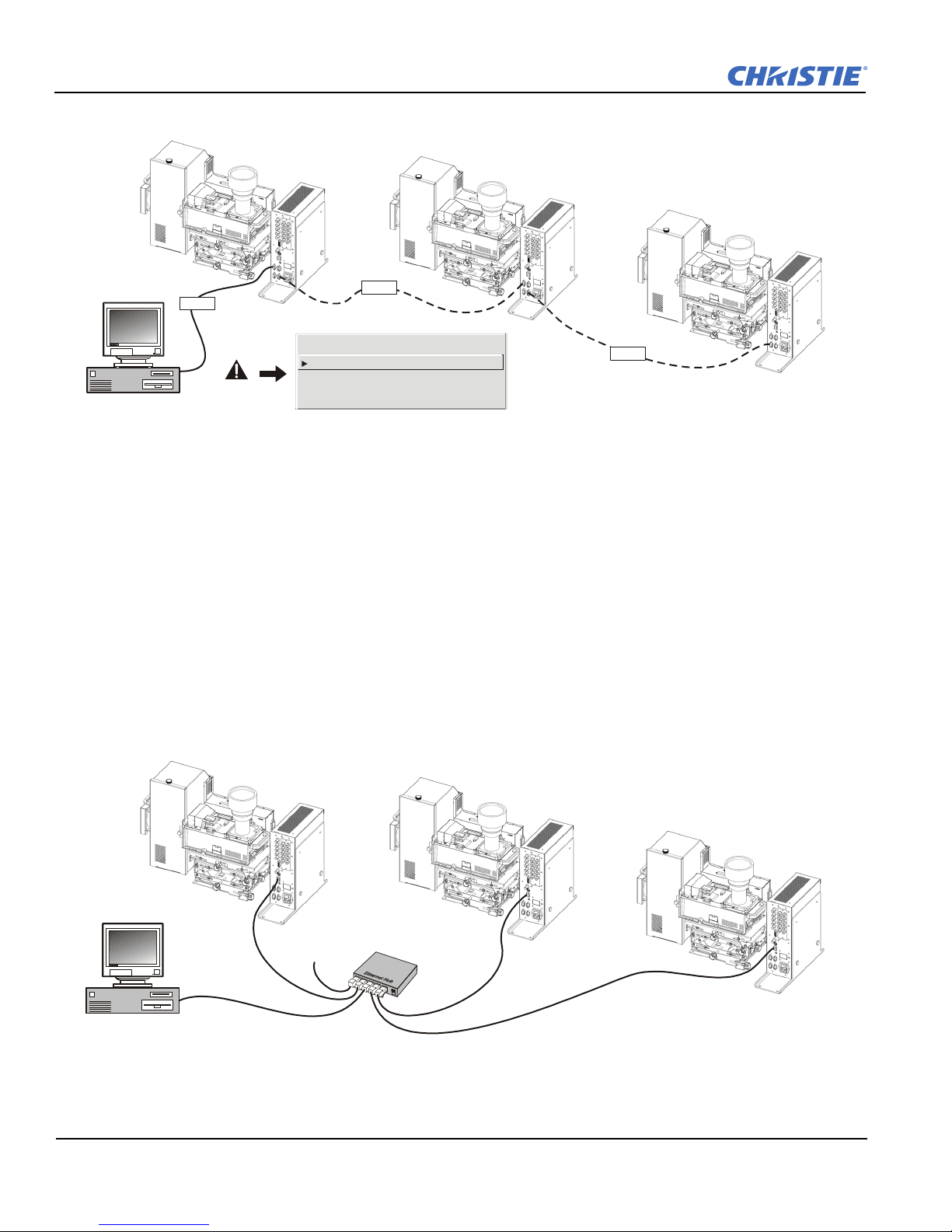
2.4.4 Connecting Multiple Projectors
RS-232 IN
RS-232 OUT RS-232 IN
RS-232 OUT RS-232 IN
FIGURE 2-20 COMMUNICATING THROUGH RS-232
RS-232 Network
To connect multiple projectors in a network with serial communication, connect the controlling source to the
RS-232 IN connector of the first projector in the network. Then take another serial communication cable and
connect one end to the RS-232 OUT connector and the other end to the RS-232 IN connector of the next
projector. Continue this pattern of connection with all projectors in the network. The last projector in the
network will only have a connection to the RS-232 IN connector. See Figure 2-20 Communicating through RS-
232.
Section 2: Installation and Setup
Mixed Network
To control multiple projectors with a computer/controller having an RS-422 interface, first set them all to the
same baud rate as your RS-422 controller.
NOTE: You must enable this combination of RS-422 and RS-232 in the Communications menu. Set the
“Network Routing” option to “RS-232 and RS-422 Joined”. See Section 3 for details.
Then chain the projectors together by connecting an
computer/controller through the
RS-422 port) to an RS-232 port on the next projector in the chain. Continue
RS-232 port of the first projector (already connected to the
connecting projectors in this manner until you’ve reached the last projector in the chain, so that only the last
projector has one unused
RS-232 port. See Figure 2-21 Communicating through a Mixed Network.
RPMX/RPMSP-D132U & RPMSP-D180U User Manual 2-17
020-100245-03 Rev. 1 (11-2010)
Section 2: Installation and Setup
RS-232
RS-422
RS-232
Separate
RS232 and RS422 joined
Ethernet joined
All joined
RS232 and
1.
2.
3.
4.
FIGURE 2-21 COMMUNICATING THROUGH A MIXED NETWORK
C
A
T
5
C
A
T
5
C
A
T
5
C
A
T
5
To other
Ethernet
devices
FIGURE 2-22 ETHERNET NETWORK
Communication parameters such as baud rate must be set to match the particular controlling device before
connecting as a network—refer to the documentation that came with your controlling device in order to
determine the proper baud rate. See 3.6, Adjusting System Parameters and Advanced Controls if you need help
changing the projector baud rate. Set the Network Routing to “RS-232 and RS-422 Joined” to reach all
projectors.
NOTES: 1) To avoid damage, connect only properly wired serial communication cables. See Appendix C for
details.
2) Each RS-232 communication cable must be no more than 25 feet in length. Use high quality cables.
2.4.5 Ethernet Network Setup
To add one or more projectors to an Ethernet network, use standard CAT5 cable to connect each projector’s
Ethernet port to a hub belonging to the network. A controller or PC must also be connected to the hub. See
Figure 2-22 Ethernet Network.
2-18 RPMX/RPMSP-D132U & RPMSP-D180U User Manual
020-100245-03 Rev. 1 (11-2010)
 Loading...