

Christie Roadie HD+35K User Manual

Roadie HD+35K
USER MANUAL
020-100340-02


Roadie HD+35K
USER MANUAL
020-100340-02

NOTICES
COPYRIGHT AND TRADEMARKS
© 2010 Christie Digital Systems USA, Inc. All rights reserved.
All brand names and product names are trademarks, registered trademarks or trade names of their respective holders.
REGULATORY
The product has been tested and found to comply with the limits for a Class A digital device, pursuant to Part 15 of the FCC Rules. These limits are
designed to provide reasonable protection against harmful interference when the product is operated in a commercial environment. The product
generates, uses, and can radiate radio frequency energy and, if not installed and used in accordance with the instruction manual, may cause harmful
interference to radio communications. Operation of the product in a residential area is likely to cause harmful interference in which case the user will
be required to correct the interference at the user’s own expense.
This Class A digital apparatus complies with Canadian ICES-003.
Cet appareil numérique de la classe A est conforme à la norme NMB-003 du Canada.
㧊 ₆₆⓪ 㠛ⶊ㣿 (A ) 㦒⪲ 㩚㧦䕢㩗䞿❇⪳㦚 䞲 ₆₆㧊㡺┞ 䕦ⰺ㧦 ⡦⓪ ㌂㣿㧦⓪ 㧊㩦㦚 㭒㦮䞮㔲₆ ⧒Ⳇ , Ṗ㩫 㣎㦮 㰖㡃㠦㍲ ㌂㣿䞮⓪ ộ㦚 ⳿㩗
㦒⪲ 䞿┞┺ .
GENERAL
Every effort has been made to ensure accuracy, however in some cases changes in the products or availability could occur which may not be reflected
in this document. Christie reserves the right to make changes to specifications at any time without notice. Performance specifications are typical, but
may vary depending on conditions beyond Christie's control such as maintenance of the product in proper working conditions. Performance
specifications are based on information available at the time of printing. Christie makes no warranty of any kind with regard to this material, including,
but not limited to, implied warranties of fitness for a particular purpose. Christie will not be liable for errors contained herein or for incidental or
consequential damages in connection with the performance or use of this material.
The product is designed and manufactured with high-quality materials and components that can be recycled and reused. This symbol means
that electrical and electronic equipment, at their end-of-life, should be disposed of separately from regular waste. Please dispose of the product
appropriately and according to local regulations. In the European Union, there are separate collection systems for used electrical and electronic
products. Please help us to conserve the environment we live in!
Canadian manufacturing facility is ISO 9001 and 14001 certified.
WARRANTY
For complete information about Christie’s limited warranty, please contact your Christie dealer. In addition to the other limitations that may be
specified in Christie’s limited warranty, the warranty does not cover:
(a) Damage occurring during shipment, in either direction.
(b) Projector lamps (See Christie’s separate lamp program policy).
(c) Damage caused by use of a projector lamp beyond the recommended lamp life, or use of a lamp supplied by a supplier other than
Christie.
(d) Problems caused by combination of the product with non-Christie equipment, such as distribution systems, cameras, video tape
recorders, etc., or use of the product with any non-Christie interface device.
(e) Damage caused by misuse, improper power source, accident, fire, flood, lightening, earthquake or other natural disaster.
(f) Damage caused by improper installation/alignment, or by product modification, if by other than a Christie authorized repair service
provider.
(g) For LCD projectors, the warranty period specified applies only where the LCD projector is in “normal use.” “Normal use” means the LCD
projector is not used more than 8 hours a day, 5 days a week. For any LCD projector where “normal use” is exceeded, warranty co
verage
under this warranty terminates after 6000 hours of operation.
(h) Failure due to normal wear and tear.
PREVENTATIVE MAINTENANCE
Preventative maintenance is an important part of the continued and proper operation of your product. Please see the Maintenance section for specific
maintenance items as they relate to your product. Failure to perform maintenance as required, and in accordance with the maintenance schedule
specified by Christie, will void the warranty.

Table of Contents
Roadie HD+35K User Manual i
020-100340-02 Rev. 1 (01-2010)
1: Introduction
1.1 Using this Manual........................................................................................................................1-1
1.1.1 Labels and Marking.............................................................................................................1-2
1.1.2 35K Typographical Notations..............................................................................................1-2
1.2 Purchase Record and Service Contacts .......................................................................................1-2
1.3 Projector Overview......................................................................................................................1-3
1.3.1 How the Projector Works ....................................................................................................1-3
1.3.2 List of Components..............................................................................................................1-4
1.3.3 Key Features........................................................................................................................1-4
2: Installation and Setup
2.1 Projector Quick Setup and Installation........................................................................................2-1
2.1.1 Quick Setup..........................................................................................................................2-1
2.2 Installation Considerations ..........................................................................................................2-6
2.2.1 Screen Type .........................................................................................................................2-6
2.2.2 Screen Size...........................................................................................................................2-7
2.2.3 Screen Aspect Ratio.............................................................................................................2-7
2.2.4 Ambient Lighting.................................................................................................................2-11
2.2.5 Other Considerations ...........................................................................................................2-11
2.3 Projector Position and Mounting.................................................................................................2-12
2.3.1 Throw Distance....................................................................................................................2-12
2.3.2 Vertical & Horizontal Position............................................................................................2-13
2.3.3 Floor Mounting and Leveling..............................................................................................2-15
2.3.4 Tilting and Special Orientations..........................................................................................2-16
2.3.5 Hoisting and Stacking..........................................................................................................2-17
2.4 Installing Lens, Lamp, and Cooling ............................................................................................2-20
2.4.1 Lens Installation...................................................................................................................2-20
2.4.2 Install First Lamp.................................................................................................................2-22
2.5 Connecting Sources.....................................................................................................................2-23
2.5.1 RGB Signals ........................................................................................................................2-25
2.5.2 YPbPr Signals (Component Video)
.............................................................................................2-26
2.5.3 Composite Video .................................................................................................................2-26
2.5.4 Dual SD/HD-SDI.................................................................................................................2-27
2.5.5 Extra Video..........................................................................................................................2-28
2.5.6 Optional Inputs ....................................................................................................................2-28
2.6 Connecting Communications ......................................................................................................2-28
2.6.1 Standard IR Remotes...........................................................................................................2-29
2.6.2 Other Controllers .................................................................................................................2-30
2.7 Connecting Multiple Projectors...................................................................................................2-32
2.7.1 Serial Links..........................................................................................................................2-33
2.7.2 Ethernet Networks ...............................................................................................................2-34
2.7.3 Separating or Joining Serial Networks ................................................................................2-36
2.7.4 Communicating to All Ports................................................................................................2-38
2.7.5 Communicating to Certain Ports..........................................................................................2-39
2.7.6 Projector Numbers...............................................................................................................2-40

ii Roadie HD+35K User Manual
020-100340-02 Rev. 1 (01-2010)
Table of Contents
2.8 Connecting the Ballast.................................................................................................................2-40
2.8.1 Configuring the Ballast for Incoming AC............................................................................2-40
2.8.2 Connect to Projector.............................................................................................................2-41
2.9 Initial Switch On..........................................................................................................................2-41
2.9.1 Set Lamp Type.....................................................................................................................2-41
2.9.2 Turning ON the Projector ....................................................................................................2-42
2.9.3 Set Cable Length..................................................................................................................2-42
2.10 Maximizing Light Output..........................................................................................................2-42
2.11 Basic Image Adjustment............................................................................................................2-42
2.12 Boresight Adjustment ................................................................................................................2-43
2.12.1 Adjust Offset.....................................................................................................................2-43
2.12.2 Adjust Left/Right Boresight..............................................................................................2-44
2.12.3 Adjust Top/Bottom Boresight...........................................................................................2-44
2.12.4 Add Anamorphic Lens......................................................................................................2-45
2.13 Internal Optical Adjustments.....................................................................................................2-45
2.13.1 Contrast Ratio Adjustment................................................................................................2-45
2.13.2 Color Gamut Adjustment..................................................................................................2-46
2.13.3 Maximizing Brightness.....................................................................................................2-46
2.13.4 DMD Convergence ...........................................................................................................2-46
2.13.5 Fold Mirror Adjustment....................................................................................................2-46
2.14 IR Remote Protocols and Adjustment .......................................................................................2-47
2.14.1 Standard IR Remote Protocols..........................................................................................2-48
2.14.2 Converting a Remote .........................................................................................................2-49
3: Operation
3.1 Projector Basics ...........................................................................................................................3-1
3.1.1 Air Filter...............................................................................................................................3-1
3.1.2 Ballast Breaker/Power Switch (ON/OFF)............................................................................3-2
3.1.3 Control Panel (Rear of Projector) ........................................................................................3-2
3.1.4 Handles.................................................................................................................................3-3
3.1.5 Channels for FredFrame™...................................................................................................3-3
3.1.6 Lens Mount & Anamorphic Lens Mount.............................................................................3-3
3.1.7 Lens Mount and Projection Lenses......................................................................................3-3
3.1.8 Input Panel ...........................................................................................................................3-3
3.1.9 Lamp ....................................................................................................................................3-4
3.1.10 Leveling Feet......................................................................................................................3-4
3.1.11 DC Power Cables...............................................................................................................3-4
3.1.12 Projection Head..................................................................................................................3-4
3.1.13 Rear Connection Panel.......................................................................................................3-4
3.1.14 Security Locks....................................................................................................................3-6
3.2 Using the Built-In Keypad or Remotes........................................................................................3-6
3.2.1 Built-in Keypad....................................................................................................................3-6
3.2.2 Standard IR Remote and Transmission................................................................................3-7
3.2.3 Wired IR Remote .................................................................................................................3-7
3.2.4 The Lite Remote (Optional).................................................................................................3-8
3.2.5 Guide to Keypads.................................................................................................................3-9

Table of Contents
Roadie HD+35K User Manual iii
020-100340-02 Rev. 1 (01-2010)
3.2.6 Keypad and Standard IR Remote Functions........................................................................3-9
3.3 Power-up Procedure/Checklist ....................................................................................................3-15
3.4 Power-down Procedure................................................................................................................3-16
3.5 Navigating through the Menu System.........................................................................................3-16
3.5.1 On-line Help ........................................................................................................................3-17
3.5.2 Time-outs.............................................................................................................................3-18
3.5.3 The Global Icon ..................................................................................................................3-18
3.5.4 The PIP Icon .......................................................................................................................3-18
3.5.5 Using Slidebars and Other Controls ....................................................................................3-18
3.5.6 Editing Text .........................................................................................................................3-19
3.5.7 Editing Numerical Values....................................................................................................3-20
3.6 Adjusting the Image.....................................................................................................................3-21
3.6.1 Before You Begin................................................................................................................3-21
3.6.2 Size and Position Menu .......................................................................................................3-21
3.6.3 Image Settings Menu...........................................................................................................3-27
3.7 Using Inputs and Channels..........................................................................................................3-35
3.7.1 Do I Select an Input or a Channel?......................................................................................3-35
3.7.2 Creating a New Channel......................................................................................................3-37
3.7.3 Selecting a Channel .............................................................................................................3-37
3.7.4 Available Channels in the Channel Setup Menu.................................................................3-38
3.7.5 Copying a Channel...............................................................................................................3-39
3.7.6 Deleting One or More Channels..........................................................................................3-40
3.7.7 Editing a Channel Setup ......................................................................................................3-41
3.8 Adjusting System Parameters and Advanced Controls...............................................................3-42
3.8.1 System Configuration (General Settings)............................................................................3-42
3.8.2 System Configuration (Communication).............................................................................3-44
3.8.3 System Configuration (Geometry & Color) ........................................................................3-48
3.8.4 System Configuration (Diagnostics / Calibration)...............................................................3-51
3.8.5 System Configuration (Optional Input Modules)................................................................3-54
3.9 Working with PIP........................................................................................................................3-54
3.9.1 Controlling Your PIP Image................................................................................................3-55
3.10 Working with the Lamp.............................................................................................................3-57
3.10.1 Which Lamp is Installed?..................................................................................................3-57
3.10.2 Lamp Cable Lengths..........................................................................................................3-58
3.10.3 Turning the Lamp ON/OFF...............................................................................................3-59
3.10.4 If the Lamp Will Not Turn On...........................................................................................3-60
3.10.5 Lamp Menu........................................................................................................................3-60
3.10.6 Adjusting Lamp Position (LampLOC™) ..........................................................................3-63
3.10.7 Stand-by Mode...................................................................................................................3-64
3.10.8 How Old is My Lamp? .....................................................................................................3-65
3.10.9 When to Replace the Lamp................................................................................................3-65
3.11 Status Menu...............................................................................................................................3-65
3.12 Using Multiple Projectors..........................................................................................................3-65
3.12.1 Matching Colors In Multiple Screens................................................................................3-66
3.12.2 Achieving Brightness Uniformity......................................................................................3-69
3.12.3 Edge Blending....................................................................................................................3-72

iv Roadie HD+35K User Manual
020-100340-02 Rev. 1 (01-2010)
Table of Contents
3.13 Remote Control of the Projector................................................................................................3-76
3.14 Working with the Lenses...........................................................................................................3-77
3.14.1 Anamorphic Lens...............................................................................................................3-78
3.15 Error Conditions ........................................................................................................................3-78
3.15.1 System Warnings/Errors....................................................................................................3-79
4: Maintenance
4.1 Safety Warnings and Guidelines..................................................................................................4-1
4.1.1 General Precautions .............................................................................................................4-1
4.1.2 AC / Power Precautions.......................................................................................................4-1
4.1.3 Lamp Precautions.................................................................................................................4-2
4.2 Maintaining Proper Cooling ........................................................................................................4-2
4.2.1 Ventilation............................................................................................................................4-3
4.2.2 Air Filter...............................................................................................................................4-3
4.2.3 Liquid Cooler.......................................................................................................................4-3
4.3 Maintenance and Cleaning...........................................................................................................4-3
4.3.1 Electrical ..............................................................................................................................4-3
4.3.2 Optical..................................................................................................................................4-3
4.3.3 Other Components ...............................................................................................................4-5
4.4 Replacing the Lamp & Filter .......................................................................................................4-5
4.4.1 Lamp Replacement Procedure .............................................................................................4-5
4.4.2 Filter Replacement Procedure..............................................................................................4-9
4.5 Replacing a Lens..........................................................................................................................4-10
5: Troubleshooting
5.1 Power ...........................................................................................................................................5-1
5.1.1 Projector Does Not Power ON.............................................................................................5-1
5.2 Lamp............................................................................................................................................5-1
5.2.1 Lamp Does Not Ignite..........................................................................................................5-1
5.2.2 Lamp Suddenly Goes OFF...................................................................................................5-1
5.2.3 Flicker, Shadows Or Dimness..............................................................................................5-2
5.2.4 LampLOC™ Does Not Seem to Work................................................................................5-2
5.2.5 LiteLOC™ Does Not Seem to Work...................................................................................5-2
5.3 Calibrating the Lens Mount.........................................................................................................5-3
5.4 Built In Keypad............................................................................................................................5-3
5.4.1 Projector ON, but No Backlight on Built-In Keypad...........................................................5-3
5.5 Image Displays ............................................................................................................................5-3
5.5.1 Blank Screen, No Display of Image.....................................................................................5-3
5.5.2 Severe Motion Artifacts.......................................................................................................5-3
5.5.3 Image Appears Vertically Stretched or ‘Squeezed’ into Center of Screen..........................5-4
5.5.4 The Projector is ON, but There is No Display.....................................................................5-4
5.5.5 The Display is Jittery or Unstable........................................................................................5-4
5.5.6 The Display is Faint.............................................................................................................5-4
5.5.7 The Upper Portion of the Display is Waving, Tearing or Jittering......................................5-4
5.5.8 Portions of the Display are Cut OFF or Warped to the Opposite edge................................5-4

Table of Contents
Roadie HD+35K User Manual v
020-100340-02 Rev. 1 (01-2010)
5.5.9 Display Appears Compressed (Vertically Stretched)..........................................................5-5
5.5.10 Data is Cropped from Edges..............................................................................................5-5
5.5.11 Display Quality Appears to Drift from Good to Bad, Bad to Good..................................5-5
5.5.12 Display has Suddenly Froze ..............................................................................................5-5
5.5.13 Colors in the Display are Inaccurate.................................................................................5-5
5.5.14 Display is Not Rectangular...............................................................................................5-5
5.5.15 Display is “Noisy”............................................................................................................5-5
6: Specifications
6.1 Display.........................................................................................................................................6-1
6.1.1 Panel Resolution and Refresh Rate......................................................................................6-1
6.1.2 Achievable Brightness.........................................................................................................6-1
6.1.3 Achievable Contrast Ratio...................................................................................................6-1
6.1.4 Colors and Gray Scale .........................................................................................................6-1
6.1.5 Gamma.................................................................................................................................6-1
6.2 Lenses..........................................................................................................................................6-2
6.3 Inputs ...........................................................................................................................................6-2
6.3.1 Analog: RGB / YPbPr (5 BNCs at INPUT 1) .....................................................................6-2
6.3.2 Analog: Video (INPUTS 3 and 4) .......................................................................................6-2
6.3.3 Analog: Sync (Interlaced or Progressive Scan Format).......................................................6-3
6.3.4 DVI-I (INPUT 2) .................................................................................................................6-3
6.3.5 Dual SD/HD-SDI (INPUT 5 or 6, Standard with Projector) ..............................................6-3
6.4 Control.........................................................................................................................................6-4
6.4.1 Wired Remote (Converted from IR Remote) ....................................................................6-4
6.4.2 IR Remote............................................................................................................................6-4
6.4.3 Ethernet................................................................................................................................6-4
6.4.4 RS-232 Serial Input .............................................................................................................6-4
6.4.5 RS-422 Serial Input .............................................................................................................6-4
6.4.6 GPIO Input..........................................................................................................................6-5
6.4.7 Control Port (From Ballast).................................................................................................6-5
6.4.8 Ballast Ports.........................................................................................................................6-5
6.5 Power...........................................................................................................................................6-5
6.5.1 Projection head ....................................................................................................................6-5
6.5.2 7 kW 3-Phase Ballast (38-814001-51).................................................................................6-6
6.6 Lamps ..........................................................................................................................................6-6
6.7 Reflectors.....................................................................................................................................6-7
6.8 Audible Noise..............................................................................................................................6-7
6.9 Safety...........................................................................................................................................6-7
6.10 EMC Emissions.........................................................................................................................6-7
6.11 EMC Immunity..........................................................................................................................6-7
6.12 Operating Environment .............................................................................................................6-7
6.12.1 Non-Operating Environment .............................................................................................6-7
6.12.2 Weight & Size....................................................................................................................6-8
6.13 Standard and Optional Components..........................................................................................6-9
6.13.1 Standard (Sold with Product).............................................................................................6-9
6.13.2 Optional (Sold Separately).................................................................................................6-9

vi Roadie HD+35K User Manual
020-100340-02 Rev. 1 (01-2010)
Table of Contents
A: Serial Communication Cables
A.1 Serial Links to Projector .............................................................................................................A-1
A.1.1 General Communications....................................................................................................A-1
A.1.2 Software Downloads...........................................................................................................A-1
A.1.3 RS-422 Connections............................................................................................................A-1
B: Menu Tree
B.1 OnScreen Menu Tree ..................................................................................................................B-1
C: System Integration
C.1 Introduction.................................................................................................................................C-1
C.1.1 Configuring the GPIO .........................................................................................................C-1
C.1.2 Query Command .................................................................................................................C-2
C.1.3 Real Time Event..................................................................................................................C-2
D: Optional Input Modules
D.1 DVI Input Module.......................................................................................................................D-1
D.2 Dual SD/HD-SDI Module...........................................................................................................D-1

Roadie HD+35K User Manual 1-1
020-100340-02 Rev. 1 (01-2010)
1 Introduction
Every effort has been made to ensure the information in this document is accurate and reliable; however, due to
constant research, the information in this document is subject to change without notice.
1.1 Using this Manual
USERS/OPERATORS: This manual is intended for trained users authorized to operate professional high-
brightness projection systems, located in restricted areas, such as projection rooms in theatres. Such users may
also be trained to replace the lamp and air filter, but cannot install the projector or perform any other functions
inside the projector.
NOTE: Only personnel trained specifically by Christie on lamp replacement and lamp safety may handle the
lamp.
SERVICE: Only Christie accredited service technicians knowledgeable about all potential hazards associated
with high voltage, ultraviolet exposure, and high temperatures generated by the lamp and associated circuits
are authorized to 1) assemble/install the projector and 2) perform service functions inside the projector.
This manual contains the following sections:
•
Section 1 Introduction
• Section 2 Installation and Setup
• Section 3 Operation
• Section 4 Maintenance
• Section 5 Troubleshooting
• Section 6 Specifications
• Section Appendix A: Serial Communication Cables
• Section Appendix B: Menu Tree
• Section Appendix C: System Integration
• Section Appendix D: Optional Input Modules
Disclaimer: Every effort has been made to ensure the information in this document is accurate and reliable.
However, due to constant research, the information in this document is subject to change without
notice. Christie Digital Systems assumes no responsibility for omissions or inaccuracies. Updates to
this document are published regularly, as required. Please contact Christie Digital Systems for
availability.

1-2 Roadie HD+35K User Manual
020-100340-02 Rev. 1 (01-2010)
Section 1: Introduction
1.1.1 Labels and Marking
Observe and follow any warnings and instructions marked on the projector.
Danger symbols are used to alert situations where the user will become
seriously injured if they do not follow the advice in this section.
Warning symbols are used to alert situations where there is a situation where a user
may be injured.
Caution symbols are used to convey information where equipment damage will occur.
1.1.2 35K Typographical Notations
The following notations are used throughout this manual:
• Keypad commands and PC keystrokes appear in bold small caps, such as
POWER, INPUT, ENTER etc.
• References to specific areas of the document appear italicized and underlined. When viewed online, the text
appears in blue indicating a direct link to that section. For example, Section 2 Installation and Setup
.
• References to other documents appear italicized and bold, such as Service Manual.
• References to software menus and available options appear italicized, such as Main menu,
Preferences.
• User input or messages that appear on screen, in status display units or other control modules appear in
Courier font. For example. “No Signal Present”, Login: christiedigital.
• Error codes, LED status appear in bold, e.g. LP, A1, etc.
• Operational states of modules appear capitalized, such as switch ON/OFF.
1.2 Purchase Record and Service Contacts
Whether the projector is under warranty or the warranty has expired, Christie’s highly trained and extensive
factory and dealer service network is always available to quickly diagnose and correct projector malfunctions.
Complete service manuals and updates are available for all projectors. Should a problem be encountered with
any part of the projector, contact your dealer. In most cases, servicing is performed on site. If you have
purchased the projector, fill out the information below and keep with your records.
* The serial number can be found on the license label located on the back of the projector.
Table 1.1 Purchase Record
Dealer:
Dealer or Christie Sales/Service Contact Phone Number:
Projection Head Serial Number*:
First Lamp Serial Number:
Lens Serial Number:
Lamp Ballast Serial Number:
Purchase Date:
Installation Date:
Section 1: Introduction
Roadie HD+35K User Manual 1-3
020-100340-02 Rev. 1 (01-2010)
At manufacture, the following Ethernet settings were defined in the projector:
1.3 Projector Overview
The Roadie HD+35K is a revolutionary split-body DMD
projector utilizing 3-chip Digital Light Processing (DLP)
technology from T exas Instruments. Its unique separation
of projection head and lamp ballast means both parts can
be flown and rigged with greater ease, creating the ideal
solution for challenging rental/staging installations and
tight spaces. With 2048 x 1080 resolution, light output of
32,500 ANSI lumens (35,000 centre lumens), and 10-bit
image processing all standard, Roadie HD+35K images
are stunning in their size, brilliance and quality. This
tough, user-friendly projector is built for frequent
transport and quick setup, even on sprawling networksperfect for any large audience venue demanding effortless
installation, and operation.
1.3.1 How the Projector Works
Processing and Projection
The Roadie HD+35K accepts a variety of signals for projection in large screen applications. The High
brightness light is generated by a short-arc Xenon lamp, and then modulated by three Digital Micromirror
Device (DMDs) panels responding to incoming data streams of digitized red, green, or blue color information.
As these digital streams flow from the source, light from the responding "ON" pixels of each panel is reflected,
converged and then projected to the screen through one or more front lenses, where all pixel reflections are
superimposed in sharp full-color images.
Stacking and Rigging
Rigging a single projector is possible using the projector's handles together with a set of optional rigging
clamps and standard rigging techniques. Alternatively, a projector secured in an optional FredFrame™ can be
stacked and if desired, flown with another framed projection head using the rigging clamps provided in the
optional Rigging Kit. Each frame provides precision roll, pitch and yaw adjustments of the projector for
precision image alignments. Corresponding lamp ballasts can be locked up to 100 feet away, flown, or not.
NOTE: Any overhead suspension used MUST be suitably rated for the weight of the projector.
Table 1.2 Ethernet Settings
Default Gateway N/A
DNS Server N/A
Projector DLP Address
Projector Mgmt IP Address 0.0.0.0 (ENABLES USE OF DHCP SERVER FOR IP ADDRESS)
Subnet Mask 255.255.255.0 (FIXED)
Lamp Ballast (7kW)
Up to 100 ft. Cables

1-4 Roadie HD+35K User Manual
020-100340-02 Rev. 1 (01-2010)
Section 1: Introduction
1.3.2 List of Components
The following components make up a complete Roadie HD+35K system (refer to Figure 3-1):
• Projection Head. Includes:
•Line cord
• Standard IR remote (includes batteries for IR use, and 25’ cable for wired use)
• Security keys for lamp and Igniter service access, plus assorted Allen keys
• Lamp Ballast (7 kW)
• Cable kit (includes 2 lamp power cables and 2 communication/control cables)
• Choice of lamp kit (includes protective gear)
• Choice of lens (Anamorphic lens and mount are also both optional)
1.3.3 Key Features
General
• 3-chip electronics with true 2048 x 1080 native resolution
• Split-projector design; ballast is separate from projection head
• Versatile electronic and optical scaling to automatically maximize the display
• 10-bit digital processing (8-bit for interlaced high-definition video)
• Can be rigged, flown and/or stacked with optional FredFrame™ hardware
Lamps / Light Output
• Choice of four Xenon bubble lamp sizes and ratings
• Light output of 32,500 ANSI lumens (35,000 centre lumens) (6kW lamp)
• Standard achievable contrast ratio 500:1 ANSI, up to 2800:1 full field ON/OFF
• LampLOC™ motorized lamp alignment (auto or custom adjustment)
• LiteLOC™ for maintaining brightness over time
• Internal electromechanical shutter for quick picture mute and black stand-by
• Optional internal optical components for improved contrast ratio and/or wider color gamut
Inputs
There are two different types of input face plate configurations (model dependant). Refer to Figure 1-1
and
Figure 1-2
. These configurations may include the following inputs:
• One analog RGBHV/YPbPr input with 5 BNCs
• One DVI-I input for either digital RGB/YCrCb or analog RGB/YPbPr signals
• One analog composite-video input, one analog S-video input
• Built-in multi-standard decoder (NTSC, NTSC 4.43, PAL, PALM, PALN, PAL60, SECAM)
• One Dual SD/HD-SDI input (installed in one of two optional input slots)
• Up to 220 MHz pixel rate
• Compatible with all current HDTV formats
• Motion adaptive de-interlacing of 50 fps- and 60 fps-originated standard and high-definition interlaced
sources
• Inverse telecine de-interlacing of film-originated standard and high-definition interlaced material with 3:2
drop-down (60 fps) or 2:2 drop-down (50 fps).
For simplicity, this manual refers to the configuration shown in Figure 1-1
only.

Section 1: Introduction
Roadie HD+35K User Manual 1-5
020-100340-02 Rev. 1 (01-2010)
Figure 1-1
Figure 1-2
Lenses
• Choice of standard high-brightness zoom lenses (ranging from 0.8:1 up to 8.5:1)
• Adjustable zoom, focus, and horizontal and vertical offsets
• Optional lens mount for 1.26x anamorphic lens producing 2.39:1 "scope" images
• Motorized Lens Mount to set focus, zoom, and horizontal and vertical offsets
• Motorized Zoom kit (optional lens accessory) is available for lens upgrade
Special Display Functions (Selected Functionality)
•Auto setup
• Picture-in-Picture (PIP)
• Electronic brightness uniformity, whitelevel edge blending and color matching
• Optional image warping/blending for unusual angles and/or screens (Christie TWIST)
I
n
p
u
t
5
(
O
p
t
.
1
)
I
n
p
u
t
6
(
O
p
t
.
2
)
E
t
h
e
r
n
e
t
I
n
p
u
t
4
S
-
V
i
d
e
o
I
n
p
u
t
3
V
i
d
e
o
I
n
p
u
t
2
D
V
I
R
S
4
2
2
R
S
2
3
2
I
N
G
P
I
O
O
U
T
R
S
2
3
2
R
e
m
o
t
e
I
n
p
u
t
1
R
e
d
G
r
e
e
n
B
l
u
e
H
o
r
/
C
o
m
p
V
e
r
t
S
y
n
c
Inp u t 5
(Op t. 1)
Inp u t 6
(Op t. 2)
Inp u t 2
DVI
IN
RS422
RS232
GPIO
OUT
RS232
Ethernet
Remote

1-6 Roadie HD+35K User Manual
020-100340-02 Rev. 1 (01-2010)
Section 1: Introduction
Communications and Diagnostics
• Built-in keypad and convertible IR-to-wired remote
• Front and rear IR sensors
• Ethernet, RS232, RS422, and GPIO control ports
• Built-in ChristieNET™ connectivity and control
• LED for two-digit error codes, plus LCD for text-based status display
• Large status light for long-distance alerts
• Double voltmeters: one for lamp ballast, one for projection head

Roadie HD+35K User Manual 2-1
020-100340-02 Rev. 1 (01-2010)
2 Installation and Setup
This section explains how to install, connect and optimize the projector for delivery of superior image quality.
Illustrations are graphical representations only and are provided to enhance the understanding of the written
material.
2.1 Projector Quick Setup and Installation
Follow these steps for quick setup of the projector in a basic front-mount position. Refer to the remaining
subsections for detailed setup instructions.
Always power down the projector and disconnect all power sources before servicing
or cleaning.
Refer to
Section 4.1 Safety Warnings and Guidelines.
2.1.1 Quick Setup
1. Position the Projection Head.
Locate the projection head at an appropriate throw distance (projector-to-screen distance) and vertical
position. Refer to Section 2.3 Projector Position and Mounting
and the Christie website for Throw
Distance calculations. Refer to Section 6.2 Lenses
. Make sure that the projector is level from side-to-side,
and is not inverted. The projector’s front-to-back and side-to-side tilt can be no more than 15 degrees from
horizontal. Position the lamp ballast so that its four cables can reach the rear of the projection head.
2. Install the Lamp and Lens.
Refer to Section 2.4 Installing Lens, Lamp, and Cooling
for installation instructions.
3. Connect a Source.
Connect your desired source to the appropriate connector(s) on the main Input panel, located on the side of
the projector (lens side) as shown in Figure 2-1
.
Figure 2-1 Connect to Input Panel

2-2 Roadie HD+35K User Manual
020-100340-02 Rev. 1 (01-2010)
Section 2: Installation and Setup
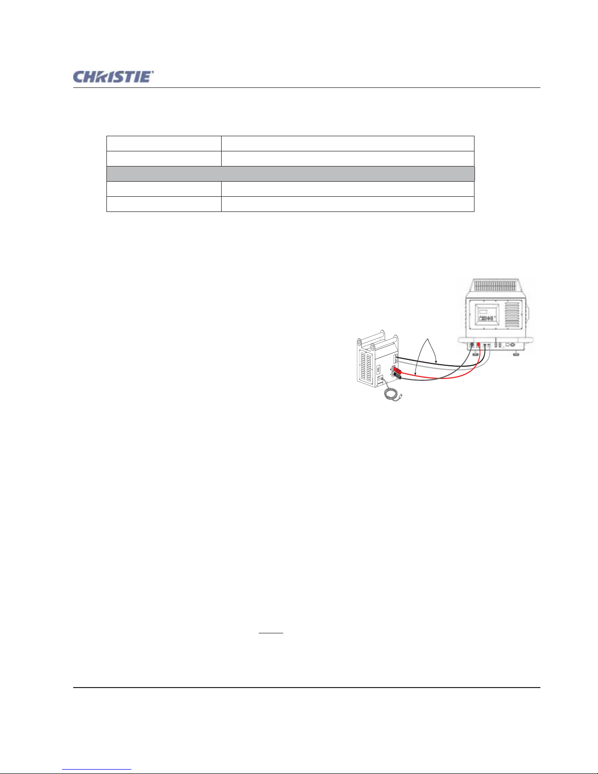
4. Connect to Lamp Ballast and Power.
1) Connect all four cables to the projection head prior to switching the ballast’s
breaker/power switch ON. 2) Follow all labeling exactly.
Head to Ballast
Connect all four ballast cables. There are two DC power cables, and two communication/control cables
between the projector rear and lamp ballast as shown in Figure 2-2
.
Figure 2-2 Connect Head to Ballast
Ballast to AC
Refer to Figure 2-3.
NOTE: Before connecting the ballast to the AC supply , a Christie accr edited service technician must make sur e the
ballast's plug type and Input Power Range Switch match the line voltage available at the site. Remove the
lamp ballast cover to access the switch and determine it's setting-toggle LEFT for 200 VAC supplies,
toggle RIGHT for 400 VAC supplies (factory default=200 VAC). Change the plug type as necessary as a
delta load with safety ground has no neutral.
Connect the ballast's integral three-phase 30-amp line cord to your AC supply. You may have to change the
plug type for your site.
Projector Rear

Section 2: Installation and Setup
Roadie HD+35K User Manual 2-3
020-100340-02 Rev. 1 (01-2010)
Confirm that the ballast's three-phase status lights are ON and that the adjacent voltmeter displays an
acceptable AC level for your ballast, and region. Refer to Section 6 Specifications
for details. Then switch
the ballast’s breaker/power switch to the ON position.
NOTE: The ballast's internal fan is the only indication whether or not the breaker/power switch is ON. Lights
on the ballast indicate only that the ballast is plugged in.
Figure 2-3 Ballast Connection and Switch On
Head-to-AC
Connect the Christie-supplied IEC 320 (220V) 15-amp line cord to your AC supply. Do not substitute
other cords. Input power required is 200 - 240 VAC (nominal), 50/60 Hz @ 3A for 208V. Refer to Figure
2-4.
Voltmeter (400V)
3-phase
Interlocks
Control
+ DC
– DC
6’ line cord
Connect to AC supply:
• 200 VAC in N. America
• 208 VAC in Japan
• 380/400/415 VAC in Europe
(Modify plug as necessary)
Connect
to projector
Breaker/Power
Switch in ON position
Check
status
1.
2.
4.
3.
NOTE: Internal switch setting must match AC availableat the site.Incoming Line Voltage

2-4 Roadie HD+35K User Manual
020-100340-02 Rev. 1 (01-2010)
Section 2: Installation and Setup
Figure 2-4 Connect Head to AC
Do not attempt operation if the AC level is not within the specified voltage, and
power range for the projection head.
At this point, the projection head is in a type of "standby" mode only. The voltmeter should display the
incoming voltage, the adjacent main PROJ. STATUS light should be yellow, and the light engine
compartment fans running, but the rest of the projection head should be OFF.
5. Set the lamp type.
EXPLOSION HAZARD. Keep the projection head OFF until you have defined which
lamp type is installed.
Before switching the projector ON and igniting the lamp, you must define in memory which size lamp is
installed; otherwise, you risk severely over driving or under driving a lamp.
NOTE: Ensure that you record the lamp size on the "Lamp Installed" label.
a. Press MENU. The Status Display at the rear of the projector shows a "Lamp Size" of 2000, 3000, 4500
or 6000 watts, depending on its last setting. The Factory default is 6000 watts.
b. Enter either the Lamp Password. Refer to Figure 2-5
.
NOTE: The password is required unless the "Enable Password" service option has been turned OFF.
Projector Rear
To AC
200-240 VAC

Section 2: Installation and Setup
Roadie HD+35K User Manual 2-5
020-100340-02 Rev. 1 (01-2010)
Figure 2-5 Setting Lamp Size
c. Use the UP/DOWN ARROWS to select which lamp is currently installed. Make sure the lamp type is also
indicated on the lamp door label.
Once the Status Display shows the correct lamp type, the projector and lamp can be switched ON.
NOTE: Lamp size can also be changed in the Service menu (Service password required) if the projector is
running, but it will not take effect until the next power-up. Whenever possible, define the lamp size before
igniting the lamp
.
6. Switch the projector and lamp ON. Using either the built-in keypad or the standard IR remote, do one of
the following to switch the projector ON, and ignite the lamp:
• press and hold
POWER for at least two seconds
•press
POWER and then press the UP or DOWN Arrow key (useful if you are unsure of the present state of
the projector)
•press
POWER twice quickly to toggle from the projector’s present ON/OFF state
The main PROJ. STATUS light at the rear of the projector should be green when the projector is up-andrunning. For best results, let the projector warm up for about 5 minutes.
7. Select the source. Using either the IR remote or built-in keypad, press the appropriate Input key (1-6) to
display the image for the corresponding source connected as described in Step 3. The display will resize as
needed, producing an image as large as possible for the type of source present.
8. Adjust the Image. Adjust the more common image settings, such as Brightness, Contract, Gamma, etc.
using the keys directly on the standard IR remote.
You can also access the Menu system and adjust these and other image settings by pressing
MENU on the
standard IR remote.
,DMT
Press “Menu” before power up.
Screen below displays lamp size.
1.
3.
Or standard Christie service password.
2.
D
Lamp Size
6000
Select installed lamp size:
2000
3000
4500
6000
on the
s
tandard
IR remote
on built-in
keypad
or
HOW TO SET THE LAMP SIZE:
on the
standard
IR remote
or
Enter Lamp Password:
on built-in
keypad
D
(MOTSỻ(MOTSỻ (MOTSỻ(MOTSỻ
7
4
1
0
2-6 Roadie HD+35K User Manual
020-100340-02 Rev. 1 (01-2010)
Section 2: Installation and Setup
9. Adjust the lens. Use the Focus button on the standard IR remote or the built-in keypad to focus the image.
Use the Zoom buttons to increase or decrease image size (not available with fixed 0.8:1 and 1:1 lenses).
Use the Lens Shift button, and the ARROW keys to shift the image location. Refer to Section 3.14
Working with the Lenses on how to use the motorized lens mount and Section 2.4.1 Lens Installation for
instructions.
10. Set Cable Length. In the
Lamp menu, set the "Cable Length (m)" slidebar to match the length of the high-
voltage DC cables connected between your lamp ballast and projection head. This regulates the voltage
drop that occurs over distance, and ensures that adequate voltage reaches the lamp. Particularly in
projectors rented for temporary installations, this setting may have to be changed from its last use.
Adjustment range is 2-30m (6½-100 ft.).
Setting the "Cable Length" also allows you to achieve the same lumens, regardless of cable length.
However, to drive the lamp at maximum power, even with the shorter ballast cables, set "Cable Length" to
maximum power. Due to the resistance losses that occur with longer ballast cables, the ballast does not
achieve the same maximum power.
Press
AUTO SETUP and/or MENU to refine other display parameters as necessary. Refer to Section 3.6.3
Image Settings Menu.
2.2 Installation Considerations
Although the Roadie HD+35K is carefully engineered to deliver exceptional quality , high brightness, and high
resolution output, your final display results could still be compromised if the projector is improperly installed.
This subsection discusses issues to consider before proceeding with a final installation. Even for temporary
installations, this information helps you to better understand what may be done to ensure optimized images.
2.2.1 Screen Type
Front Screen Installations
This projector is intended for use with flat or slightly curved screens, front or rear, ranging from about 1.5
meters (5 ft.) to 45 meters (150 ft.) wide. Although flat screens generally offer a low gain similar to a matte
white wall paint-approximately 1 with a viewing angle just under 180°- and are considered most effective
when ambient light is low, this difference in gain may be negligible given the very high light output from this
projector. In addition, incident light reflects equally in all directions so the audience can see the display from
more acute viewing angles. See Figure 2-6
.
Figure 2-6 Audience Coverage with a Flat Screen
Flat
Screen
(gain 1)
Viewing
Angle
Audience Coverage

Section 2: Installation and Setup
Roadie HD+35K User Manual 2-7
020-100340-02 Rev. 1 (01-2010)
NOTE: Roadie HD+35K lenses are designed primarily for use with flat screens, but the projector's depth-of-field
range allows the lens to be focused on mildly curved screens as well. While focus remains sharp in the
corners, there may be significant pincushion distortion, primarily at the top of the screen.
Rear Screen Installations
There are two basic types of rear screens: diffused and optical. A diffused rear screen has a surface that spreads
the light striking it. Purely diffused screens have a gain of less than 1. The main advantage of the diffused
screen is its wide viewing angle, similar to that of a flat screen for front screen projection. Optical rear screens
take light from the projector and redirect it to increase the light intensity at the front of the screen. This reduces
it in other areas, and creates a viewing cone similar to that of a curved front screen installation.
To summarize, optical screens are better suited for brightly lit rooms where the audience is situated within the
viewing cone. Diffused screens may be better suited when a wide viewing angle is required, but there is low
ambient room lighting.
2.2.2 Screen Size
Screen size (image size) may be up to 150 feet across, depending on your lens and ambient light level. Choose
a screen size appropriate for your lens and application. Keep in mind that if the projector will be used to
display much text information, the image size must allow the audience to recognize all text clearly. The eye
usually sees a letter clearly if eye-to-text distance is less than 150 times the height of the letter . In other words,
small text that is simply located too far from the eye will be illegible no matter how sharply and clearly it is
displayed.
NOTE: Screens with aspect ratios (proportion) of 4:3 are typically specified by diagonal size, but screens having
other aspect ratios, such as the 2048 x 1080 of the Roadie HD+35K, are usually specified by their
horizontal width. See
Table 2.1 below:
2.2.3 Screen Aspect Ratio
Aspect ratio describes the proportion of the display and is expressed as the ratio of width to height, such as
"5:4" or "16:9". Typical aspect ratios range from 1.25 to 2.35, the higher the value, the wider or "less square"
the image.
Refer to Table 2.2 below.
Table 2.1 Matching Lens to Screen Size
Lens Type Screen Width(< - >)
0.8:1 fixed 5 - 3 ft.
1:1 fixed 14 - 150 ft.
1.25 - 1.45:1 zoom 10 - 121 ft.
1.45 - 1.8:1 zoom 8 - 102 ft.
1.8 - 2.4:1 zoom 6 -83 ft.
2.2 - 3.0:1 zoom 5 - 66 ft.
3.0 4.3:1 zoom 3 - 49 ft.
4.3 - 6.0:1 zoom 2.5 - 35 ft.
5.5 -8.5:1 zoom 2 - 27 ft.

2-8 Roadie HD+35K User Manual
020-100340-02 Rev. 1 (01-2010)
Section 2: Installation and Setup
Although image size and aspect ratio can be adjusted using projector software, it is still ideal to use a screen
with an aspect ratio that closely matches your likely source material. You can then more easily fill the screen
with the image without restricting either image size or content. For example, standard video from a VCR has a
4:3 ratio (approximately) and can fill a 4:3 screen without side-to-side stretching, whereas a high-definition
signal with a 16:9 aspect is largest on a 16:9 screen.
Figure 2-7 Aspect Ratios: Image vs. Screens
As shown in Figure 2-7, an obvious mismatch between source material and screen is characterized by "black
bars" on both sides of the image (if the screen is wider than the source material) or above and below the image
(if the source material is wider-typically called a letterbox display).
Alternatively , if the area of unused pixels is considered minimal, you may prefer to use the projector's software
control to slightly stretch the image either horizontally or vertically-enough to utilize the remaining pixels
while not noticeably distorting the image.
Using a Cinema "Flat" Screen (1.85 aspect ratio)
By default, source signals closely matching the projector's 2048 x 1080 display area will fill this area
accordingly. Signals with lower aspect ratios will automatically scale to be as large as possible while
maintaining their original aspect ratio. For details on resizing behavior, refer to Section 3.6.3 Image Settings
Menu.
Table 2.2 Typical Aspect Ratios
Application Aspect Ratio
SXGA 1.25 (5:4)
35mm filmstrip 1.32 (4:3)
NTSC Video/XGA 1.33 (4:3)
PAL Video/XGA 1.33 (4:3)
HDTV Video 1.78 (16:9)
Letterbox Video/”Flat” 1.85 (2048 x 1080)
Roadie Native Resolution 1.89 (2048 x 1080)
Cinemascope 2.35
Image edge
Screen edge Screen edge
Image edge
on
16:9 screen
5:4 image
on
5:4 screen
16:9 image

Section 2: Installation and Setup
Roadie HD+35K User Manual 2-9
020-100340-02 Rev. 1 (01-2010)
Displaying both “Flat" and "Scope"
As an example, two standard types of displays (flat and scope) differ in their width-to-height aspect ratio as
shown below:
Figure 2-8 Typical Wide Formats
Achieving either of these displays from a variety of incoming source material (that may or may not be in the
same format) depends on proper settings in the projector as well as certain room conditions.
Projector Variables: Electronic and Anamorphic Resizing
The native resolution of the projector (1.89) closely matches the aspect ratio of "flat" source material (1.85).
Wider scope material, however, may be "squeezed" electronically that is, it is distorted into a narrower area
(characterized by unusually thin people) so that its pixels can then be stretched horizontally through the
anamorphic lens to regain the full and properly proportioned 2.39 display . This optical widening can stretch the
image by approximately 25%. See Figure 2-9
.
Figure 2-9 Typical Method for Achieving “Scope”
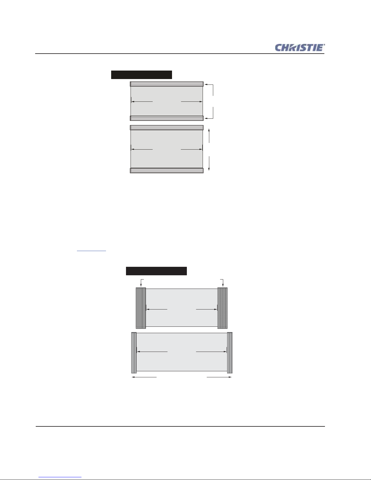
Masking Options
In order to conveniently present different types of incoming data-for example, flat vs. scope-on a single screen,
you can use physical masking to cover the unused edge(s) of the screen. These movable panels are most
commonly installed along the top edge of the screen, changing the height of the screen, but not its width, and
are most frequently used in permanent installations.
The screen shown in Figure 2-10
also has a bottom mask:
• Add masks for "scope" displays
• Remove masks for "flat" displays
“Flat” Image “Scope” Image
Aspect ratio = 1.85 Aspect ratio = 2.39
Normal “Scope” Image
A
n
a
m
o
r
p
h
Unused pixels
Screen edge
2-10 Roadie HD+35K User Manual
020-100340-02 Rev. 1 (01-2010)
Section 2: Installation and Setup
Figure 2-10 Top Masking for Scope Images
Alternatively , masks may be installed at each side of the screen in order to change the width of the screen, but
not its height.
• Add masks for "flat" displays
• Remove masks for "scope" displays
In some cases, the room will have both side and top/bottom masking installed. This arrangement is the most
flexible of all.
Refer to Figure 2-12
for a summary of the basic factors affecting wide displays in a variety of rooms.
Figure 2-11 Side Masking for Flat
2.39 image
1.85 image
Top/bottom masking
to hide screen edges
Masking moved
aside
TOP-MASKING SCREEN
(1.85 screens)
1.85 image
2.39 image
Side masking to hide screen edges
Masking moved aside
SIDE-MASKING SCREEN
(2.39 screens)

Section 2: Installation and Setup
Roadie HD+35K User Manual 2-11
020-100340-02 Rev. 1 (01-2010)
Figure 2-12 Switching between Flat and Scope Displays
2.2.4 Ambient Lighting
The extraordinary brilliance of this projector is certainly well suited for locations where ambient lighting might
be considered less than ideal for projection. Even a typical room or large auditorium fully lit with ceiling lights
and windows rarely requires special attention. Contrast ratio in your images will be noticeably reduced only if
light directly strikes the screen, such as when a shaft of light from a window or floodlight falls on the image.
Images may then appear washed out and less vibrant.
In general, avoid or eliminate light sources directed at the screen.
2.2.5 Other Considerations
Other considerations and tips that can help improve your installation:
• Keep the ambient temperature constant and below 35°C (95°F). Keep the projector away from heating and/
or air conditioning vents. Changes in temperature may cause drifts in the projector circuitry that may affect
performance.
• Keep the projector away from devices that radiate electromagnetic energy such as motors and transformers.
Common sources of these include slide projectors, speakers, power amplifiers, elevators, etc.
• Choose the best screen size for the application. Since more magnification reduces brightness, use a screen
size appropriate for the venue, but not larger than required. Installing a large screen in a small room is similar
to watching television at a close range; too large a screen can overpower a room and interfere with the overall effect. A good rule of thumb is to be no closer than 1.5 times the width of the screen.
“All the Pixels All the Time”Screen Type Quickest Scope --> Flat
TOP-MASKING SCREEN
(1.85 screens)
SIDE-MASKING SCREEN
(2.39 screens)
A
n
a
m
or
p
h
A
n
a
m
o
r
p
h
A
n
a
m
or
p
h
A
n
a
m
o
r
p
h
A
n
a
m
or
p
h
A
n
a
m
or
p
h
Masking
Masking
Masking
Flat Flat
Flat
Flat
Flat
Scope Scope
Scope
Scope
Scope
(2048 across)
(1700 across)
(1700 across,
approx.)
1280 --> 2048
1280 -->1700 (approx.)
EXTRA SHORT THROW
FIXED SIDE MASKING
and
Top and/or bottom masks present
NOTE: Example shows vertical offset
Z
O
O
M
Z
O
O
M
(Masking)
out
in
Re-size electronically with TPC
source & screen settings

2-12 Roadie HD+35K User Manual
020-100340-02 Rev. 1 (01-2010)
Section 2: Installation and Setup
2.3 Projector Position and Mounting
Installation type, the available screen, and ambient lighting all affect where the projector should be positioned.
In addition, both throw distance (the distance between the projector and screen) and vertical position (the
height of the projector in relation to the screen) must be determined for every new installation. Both depend on
the screen size and lens type you are using. Make sure that the room can accommodate the required location of
the projector for the chosen screen size.
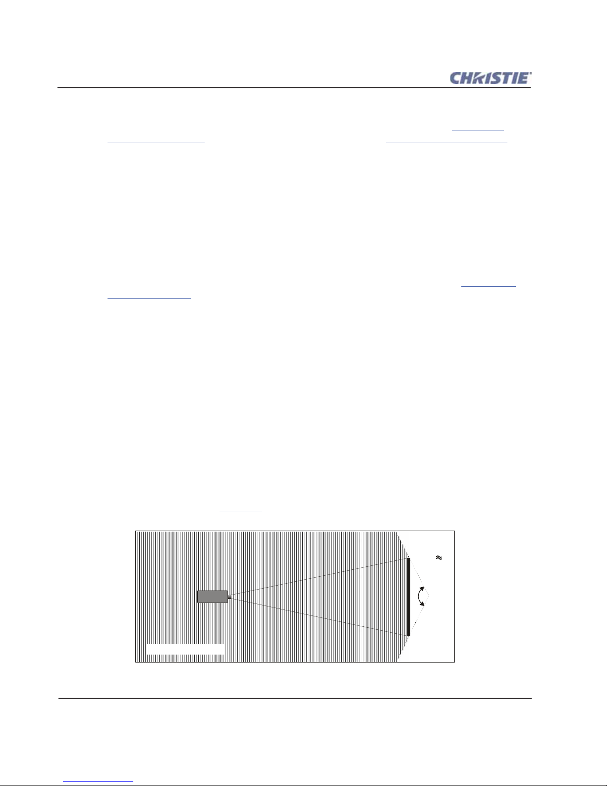
2.3.1 Throw Distance
Throw distance is the distance between the projector and the screen (see Figure 2-13). For any installation,
placing the projector at an accurate throw distance is necessary in order for the image size to closely match
your screen. The farther the projector is from the screen, the larger the image. W ith zoom lenses, you'll want to
know the approximate minimum and maximum image sizes possible from a given throw distance so that the
most appropriate lens is installed at the site (throw distance/screen width = throw ratio).
Figure 2-13 Estimating Throw Distance: Example
NOTE:
If your projector is slightly tilted in relation to the screen, typical for large venues and/or elevated
installations, throw distance still represents the smallest measurement between the screen and projector.
As shown in Figure 2-13, the throw distance is approximately equal to the horizontal width of the screen
multiplied by the type of lens you are using. For example, if you are using a 1:1 lens, proper throw distance
will be approximately the same as screen width. Once you know your screen width and type of lens, you can
estimate throw distance needed. Or, if you know throw distance, you can determine what images sizes are
possible with a given zoom lens.
x
= Approx. Throw DistanceScreen Lens Type
In this example, a throw distance of
18.75 feet will project an image
approx. 13-15 ft wide, depending
on the zoom setting.
1.25-1.45 zoom lens
Section 2: Installation and Setup
Roadie HD+35K User Manual 2-13
020-100340-02 Rev. 1 (01-2010)
IMPORTANT! For proper placement in any installation, use the lens and screen size to calculate the precise
throw distance using the tables provided in the Dealer Section of the Christie Website, PN 020100395-xx. In addition, please keep in mind that due to lens manufacturing tolerances for lens
focal length, actual throw distance can vary ±5% or more between lenses described as having the
same throw ratio.
2.3.2 Vertical & Horizontal Position
Refer to the offsets shown in this section to help determine how high or low to install the projector in relation
to the center of the screen, and/or how far off to one side.
Vertical Position
Describes the elevation of the projector in relation to the screen. For many typical rental/staging installations,
the projector is mounted above screen center. An ideal vertical position helps to ensure that images are
accurately rectangular in shape rather than distorted into a keystoned shape with non-parallel sides, that both
image focus, and brightness remains optimized.
NOTE: Proper vertical position is recommended, although vertically keystoned images (i.e., those with sloping
sides) can be corrected in software. Refer to
Section 3 Operation.
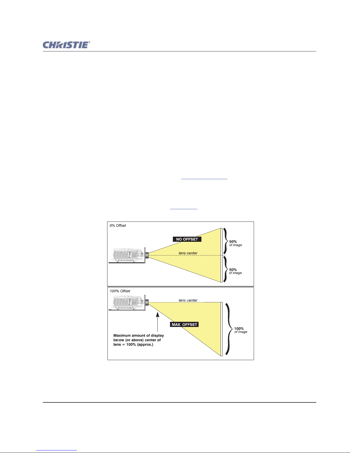
The image can be offset vertically (shifted above or below lens center) by using the built-in keypad or the
standard IR remote. Starting with no offset, the 2048 x 1080 image from this projector can be moved by a
distance of up to ±100% of the image height (depending on the lens), resulting in the entire image being
displayed above or below lens center. Refer to Figure 2-12
.
Figure 2-14 Vertical Offset Range

2-14 Roadie HD+35K User Manual
020-100340-02 Rev. 1 (01-2010)
Section 2: Installation and Setup
NOTES: 1) Assumes full 2048 x 1080 display. 2) Recommended offset range can sometimes be exceeded, however
this may affect image quality.
3) Due to manufacturing tolerances, an offset range can vary ±5% or more
between lenses described as having the same throw ratio, between projectors, and with any lens/projector
combination. 4) Simultaneous horizontal and vertical offset can limit th e adjustmen t range of ea ch, as c an
long throw distances.
ALTERNATIVE METHOD OF DESCRIBING VERTICAL OFFSET
Offset can also be specified as the distance traveled from lens center (such as 270 pixels) and expressed as
a percentage (270 pixels=50%) of half of the image height. This concept of image movement is illustrated
in the example below:
Figure 2-15 Example of Alternative Offset Specification
For any projector, if you find that you cannot raise or lower the image enough using mechanical vertical
offset, try adjusting V-Position in the
Size and Position menu when displaying at less than the minimum
size (see Section 3.6.3 Image Settings Menu
). If images remain keystoned or exhibit uneven brightness, the
projector may simply be too high or low in relation to the screen. Relocate for optimized performance.
Horizontal Position
The image can be offset horizontally (shifted left or right of lens center) by using the built-in keypad or the
standard IR remote. Starting with no offset, the 2048 x 1080 image from this projector can be moved by a
distance of up to ±35% of the image width (depending on the lens).
lens center
75%
25%
of image
of image
50% Offset
Image by a distance of
50% of half the image height
moved
 Loading...