

Christie Roadie 4K35, Roadie 4K45 Service Manual

Service Manual
020-101694-03
Roadie 4K35 and 4K45

NOTICES
COPYRIGHT AND TRADEMARKS
Copyright © 2016 Christie Digital Systems USA Inc. All rights reserved.
All brand names and product names are trademarks, registered trademarks or trade names of their respective holders.
GENERAL
Every effort has been made to ensure accuracy, however in some cases changes in the products or availability could occur which may not be reflected in this
document. Christie reserves the right to make changes to specifications at any time without notice. Performance specifications are typical, but may vary
depending on conditions beyond Christie's control such as maintenance of the product in proper working conditions. Performance specifications are based on
information available at the time of printing. Christie makes no warranty of any kind with regard to this material, including, but not limited to, implied
warranties of fitness for a particular purpose. Christie will not be liable for errors contained herein or for incidental or consequential damages in connection
with the performance or use of this material. Canadian manufacturing facility is ISO 9001 and 14001 certified.
WARRANTY
Products are warranted under Christie’s standard limited warranty, the complete details of which are available by contacting your Christie dealer or Christie. In
addition to the other limitations that may be specified in Christie’s standard limited warranty and, to the extent relevant or applicable to your product, the
warranty does not cover:
Problems or damage occurring during shipment, in either direction.
a.
Projector lamps (See Christie’s separate lamp program policy).
b.
Problems or damage caused by use of a projector lamp beyond the recommended lamp life, or use of a lamp other than a Christie lamp supplied by
c.
Christie or an authorized distributor of Christie lamps.
Problems or damage caused by combination of a product with non-Christie equipment, such as distribution systems, cameras, DVD players, etc., or use
d.
of a product with any non-Christie interface device.
Problems or damage caused by the use of any lamp, replacement part or component purchased or obtained from an unauthorized distributor of Christie
e.
lamps, replacement parts or components including, without limitation, any distributor offering Christie lamps, replacement parts or components through
the internet (confirmation of authorized distributors may be obtained from Christie).
Problems or damage caused by misuse, improper power source, accident, fire, flood, lightening, earthquake or other natural disaster.
f.
Problems or damage caused by improper installation/alignment, or by equipment modification, if by other than Christie service personnel or a Christie
g.
authorized repair service provider.
Problems or damage caused by use of a product on a motion platform or other movable device where such product has not been designed, modified or
h.
approved by Christie for such use.
Problems or damage caused by use of a projector in the presence of an oil-based fog machine or laser-based lighting that is unrelated to the projector.
i.
For LCD projectors, the warranty period specified in the warranty applies only where the LCD projector is in “normal use” which means the LCD projector
j.
is not used more than 8 hours a day, 5 days a week.
Except where the product is designed for outdoor use, problems or damage caused by use of the product outdoors unless such product is protected from
k.
precipitation or other adverse weather or environmental conditions and the ambient temperature is within the recommended ambient temperature set
forth in the specifications for such product.
Defects caused by normal wear and tear or otherwise due to normal aging of a product.
l.
The warranty does not apply to any product where the serial number has been removed or obliterated. The warranty also does not apply to any product sold
by a reseller to an end user outside of the country where the reseller is located unless (i) Christie has an office in the country where the end user is located or
(ii) the required international warranty fee has been paid.
The warranty does not obligate Christie to provide any on site warranty service at the product site location.
PREVENTATIVE MAINTENANCE
Preventative maintenance is an important part of the continued and proper operation of your product. Please see the Maintenance section for specific
maintenance items as they relate to your product. Failure to perform maintenance as required, and in accordance with the maintenance schedule specified by
Christie, will void the warranty.
REGULATORY
The product has been tested and found to comply with the limits for a Class A digital device, pursuant to Part 15 of the FCC Rules. These limits are designed
to provide reasonable protection against harmful interference when the product is operated in a commercial environment. The product generates, uses, and
can radiate radio frequency energy and, if not installed and used in accordance with the instruction manual, may cause harmful interference to radio
communications. Operation of the product in a residential area is likely to cause harmful interference in which case the user will be required to correct the
interference at the user’s own expense.
CAN ICES-3 (A) / NMB-3 (A)
이 기기는 업무용(A급)으로 전자파적합등록을 한 기기이오니 판매자 또는 사용자는 이점을 주의하시기 바라며, 가정 외의 지역에서 사용하는 것을 목적으로 합니다.
ENVIRONMENTAL
The product is designed and manufactured with high-quality materials and components that can be recycled and reused. This symbol means that electrical
and electronic equipment, at their end-of
to local regulations. In the European Union, there are separate collection systems for used electrical and electronic products. Please help us to conserve the
environment we live in!
-life, should be disposed of separately from regular waste. Please dispose of the product appropriately and according

Content
Introduction................................................. 7
Site requirements..............................................7
Physical operating environment..................................... 7
Power connection.............................................. 7
Projector components............................................8
Lamp power supply components.....................................9
Service guidelines............................................11
Ordering parts............................................... 11
Interconnections and line drawings.................................. 11
Replacing modules.............................................11
Servicing live equipment.........................................12
Safety and warning guidelines..................................... 12
AC/power precautions.........................................13
Lamp precautions........................................... 13
Product safety labels......................................... 14
Maintenance and cleaning........................................16
Ventilation and Cooling..........................................16
Inspecting and cleaning the airflow interlocks..........................16
Inspecting and cleaning the lamp blower.............................16
Inspecting and cleaning the fan extrator.............................17
Inspecting and filling the coolant reservoir............................17
Inspecting the rear exhaust assembly...............................18
Filtration...................................................18
Inspecting the light engine air filter................................ 18
Inspecting the laminar airflow device filter............................18
Inspecting and cleaning lamps..................................... 18
Removing dust from the lamp....................................19
Removing fingerprints, smudges, or oil from the lamp.....................19
Inspecting and cleaning optics..................................... 19
Tools recommended for removing dust or grease........................20
Removing dust from the projection lens..............................20
Removing fingerprints, smudge, or oil from the projection lens...............21
Roadie 4K35 and 4K45 Service Manual 3
020-101694-03 R
Copyright © 2016 Christie Digital Systems USA Inc. All rights reserved.
ev. 1 (01-2016)

Content
Service setups...............................................22
Turning the projector on......................................... 22
Turning the projector off.........................................22
Adjusting horizontal boresight......................................22
Adjusting vertical boresight.......................................23
Adjusting the fold mirror.........................................24
Aligning the integrator module..................................... 25
Converging the image...........................................26
DMD convergence...........................................26
Evaluating the image convergence.................................27
Adjusting the image convergence................................. 28
Troubleshooting............................................. 31
Projector does not power on.......................................31
Lamp does not ignite........................................... 31
Lamp suddenly turns off.........................................32
Flicker, shadows, or dimness...................................... 32
LampLOC not working...........................................32
Touch panel controller is blank..................................... 33
Blank screen, no display of image................................... 33
Cannot communicate with the projector............................... 33
Inaccurate display colors.........................................34
Display is not rectangular........................................ 34
Display has suddenly frozen.......................................34
Display is jittery or unstable.......................................34
Parts and module replacement..................................35
Maintenance prerequisites ........................................35
Tools required for service.........................................35
Index of parts and modules.......................................36
Shutting down for maintenance.....................................39
Projector covers.............................................. 39
Removing the touch panel controller................................39
Removing the projector shroud (optional)............................ 40
Removing the front top cover....................................40
Removing the light engine cover..................................41
Removing the rear top lid...................................... 42
Removing the front lamp-side cover................................42
Removing the lamp door.......................................42
Roadie 4K35 and 4K45 Service Manual 4
020-101694-03 R
Copyright © 2016 Christie Digital Systems USA Inc. All rights reserved.
ev. 1 (01-2016)

Content
Removing the front lens-side cover................................ 43
R
emoving the rear lens-side cover.................................43
Removing the rear cover.......................................44
Removing the front cover...................................... 44
Filtration...................................................45
Removing the light engine air filter.................................45
Ventilation and Cooling..........................................46
Replacing the card cage exhaust fans–bottom (fan #1 and 2)................46
Replacing the radiator fan (fan #3)................................ 46
Replacing the laminar airflow device fan (fan #4)....................... 47
Replacing the light engine fan pack (fan #5, 6, 7, and 8)...................48
Replacing the light engine fan (fan # and15).......................... 49
Replacing the card cage fan-back (fan #9)............................50
Replacing the card cage intake fans–top (fan #10, 11 and 12)............... 50
Replacing the igniter fan (fan #16)................................ 51
Replacing the HIP fan (fan #13).................................. 51
Replacing the liquid cooling pump fan (fan #14)........................ 52
Replacing the IMCB fan (fan #18).................................52
Removing the main AC blower................................... 53
Replacing the extractor fan..................................... 53
Removing the starter capacitor...................................54
Removing the liquid cooling reservoir...............................54
Removing the radiator........................................ 56
Replacing the main AC blower vane switch............................57
Replacing the remote temperature sensor module.......................58
Removing the low profile extractor.................................58
Replacing the red FPGA blower (fan #19).............................59
Replacing the firewall fan (fan #20)................................59
Optics.....................................................60
Removing the lamp.......................................... 60
Installing the lamp...........................................61
Replacing the light engine......................................62
Replacing the illumination optic system..............................64
Replacing the cold mirror.......................................65
Replacing the fold mirror.......................................66
Replacing the integrator snood...................................66
Replacing the integrator assembly.................................67
Replacing the light sensor module.................................67
Replacing the UV filter........................................ 67
Roadie 4K35 and 4K45 Service Manual 5
020-101694-03 R
Copyright © 2016 Christie Digital Systems USA Inc. All rights reserved.
ev. 1 (01-2016)

Content
Electronics..................................................68
R
eplacing the backplane.......................................68
Replacing the high speed image processor............................69
Replacing the MCPU board......................................70
Replacing the option cards......................................70
Replacing the primary environmental board...........................71
Replacing the secondary environmental board..........................71
Replacing the integrated motor control board..........................72
Replacing the lamp adjuster.....................................72
Replacing the centrifugal fan interface board.......................... 73
Power supplies...............................................73
Replacing the igniter..........................................73
Replacing the AC line filter......................................74
Replacing the AC breaker switch..................................75
Replacing the AC relay........................................ 76
Replacing the low voltage power supply..............................77
Replacing the standby power supply................................78
Lenses....................................................79
Removing the projection lens....................................79
Replacing the lens mount.......................................79
Replacing the anode yoke...................................... 80
Replacing the douser motor.....................................81
Replacing the ceramic douser plate................................ 81
Replacing the reflector and heat dump.............................. 82
Testing ground continuity and dielectric strength..........................82
Required test equipment.......................................82
Preparing the lamp power supply for testing...........................83
Testing ground continuity.......................................84
Testing dielectric strength...................................... 85
Roadie 4K35 and 4K45 Service Manual 6
020-101694-03 R
Copyright © 2016 Christie Digital Systems USA Inc. All rights reserved.
ev. 1 (01-2016)

Introduction
This document provides technical information for assisting Christie qualified technicians in the
servicing of the Roadie 4K35 and 4K45 projectors .
Every effort has been made to make sure the information in this document is accurate and complete.
However, due to continuing research all information is subject to change without notice. Christie
assumes no responsibility for omissions or inaccuracies.
Site requirements
To safely install and operate the projector, the installation location must have restricted access for
authorized personnel only and meet these minimum requirements.
Physical operating environment
Provides specifications for the operating environment.
• Maximum ambient temperature (operating) 35°C (95°F)
• Minimum ambient temperature (operating) 10°C (50°F)
Power connection
Learn the requirements for permanently wired installations or power cord connections.
• Single phase 10A IEC320C14 (lamp power supply to projector head)
or
Single phase 15A (North America)/10A (all other regions) power cord (projector head to AC
mains). The latter cord is provided for installations where the projector head is remotely
lcoated from the lamp power supply (LPS) and must be powered directly from the AC mains
instead of the LPS.
• Terminal block, electrician hard-wired at the projector headlamp power supply (LPS).
Three-phase, 39A 200-230VAC + Earth (North America and Japan)
or
Three-phase, 26A 380-415VAC + Neutral + Earth (regions outside North America and Japan)
• This product can be connected to an IT power distribution system.
Roadie 4K35 and 4K45 Service Manual 7
020-101694-03 R
Copyright © 2016 Christie Digital Systems USA Inc. All rights reserved.
ev. 1 (01-2016)
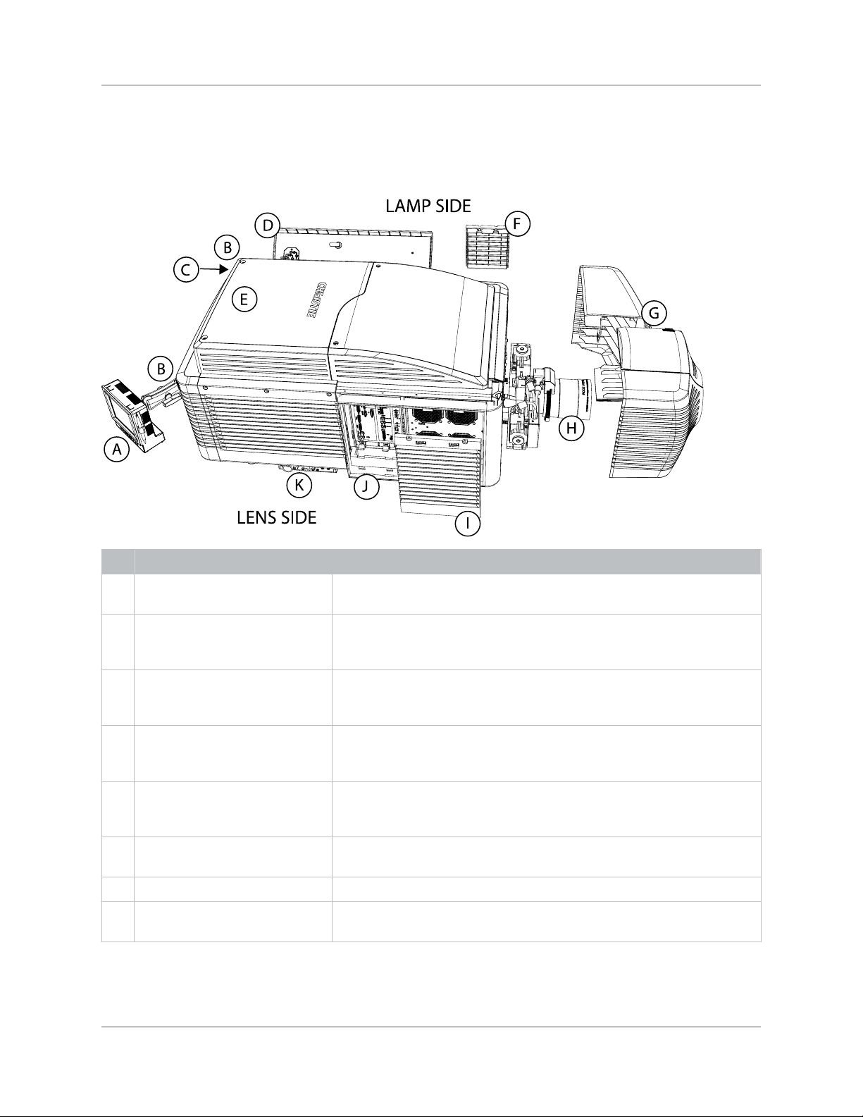
Projector components
Learn where to find the components of the projector.
Introduction
ID Item Description
A Touch panel controller (TPC) A touch-sensitive screen used to control and monitor operation. See
T
ouch panel controller.
B LED status indicators LED color and blinking rates (located in both back corners of the
projector) provide information about the status of the projector. See
Projector LED status indicators.
C Manual douser override Closing the douser rotates a shutter blade in front of the lamp and
reduces the lamp power to its minimum. The override is for emergency
use only.
D Lamp door and lamps The lamp door provides access to the lamp compartment and must
remain closed and locked for normal operation. Lamp replacement should
only be performed by qualified technicians. See Accessories.
E Low profile extractor Extracts heated air from the lamp compartment out the back of the
projector. The Roadie Ducted Exhaust kit (not shown) P/N: 113-107109xx is available to duct hot air away from the projector. See Accessories.
F Radiator access door panel The radiator door provides access to the radiator and liquid cooling
compartment and must remain closed during normal operation.
G Shroud (optional) Covers the motorized lens mount assembly (two-pieces).
H Projection lens A variety of lenses can be used with the Roadie 4K35 and 4K45. See
Accessories.
Roadie 4K35 and 4K45 Service Manual 8
020-101694-03 R
Copyright © 2016 Christie Digital Systems USA Inc. All rights reserved.
ev. 1 (01-2016)

Introduction
ID Item Description
I Air filter cover and air filter Filters the intake air before it circulates through the front compartment
to cool the main electronics. See Removing the light engine air filter (on
page
45).
J Input panel Provides a variety of ports for connecting external devices. See
Connecting devices.
K Connector box Provides connections for the DC lamp and communication cables.
Lamp power supply components
Learn the components of the lamp power supply.
ID Item Description
A Projector AC power outlet Powers the projector head. Do not use this outlet to power other devices.
B Main LPS breaker Acts as a power switch, protecting the lamp power supply (LPS) against
over-current conditions of 40A or more.
C Projector Interlock and
communication connections
D DC cable connectors Locking connectors for DC cables. These connectors are shipped
E DC lamp power cables Carries power from the LPS to the projection lamp.
Roadie 4K35 and 4K45 Service Manual 9
020-101694-03 R
Copyright © 2016 Christie Digital Systems USA Inc. All rights reserved.
ev. 1 (01-2016)
Provides communication between the projector and the LPS.
separately and must be connected by an electrician.

Introduction
ID Item Description
F Lamp breaker Acts as a power switch, protecting the LPS against over-current
conditions of 50A or more.
G Outlet breaker Acts as a power switch, protecting the projector electronics against over-
current conditions of 15 A or more.
H Power phase indicator lights Indicates the power on each of the three phases.
I LPS power inlet Supplies power to the LPS. This connection must be wired by an
electrician, according to local regulations.
Roadie 4K35 and 4K45 Service Manual 10
020-101694-03 R
Copyright © 2016 Christie Digital Systems USA Inc. All rights reserved.
ev. 1 (01-2016)

Service guidelines
Review safety guidelines and information required for replacing modules.
Ordering parts
When ordering replacement parts, quote the part numbers of the items required. Quote the projector
model number, serial number, and date of manufacture, as indicated on the license label.
Not all parts are available separately. In addition, some parts stocked as inventory are available only
until the current supply lasts.
All part numbers are subject-to-change.
Related information
Site requirements (on page
7)
Interconnections and line drawings
The interconnect diagram illustrates the path of electrical connections between modules.
Manufacturer’s part numbers are included. Part numbers are subject to change.
Line drawings provide projector dimensions and sizes for installation.
To download the latest interconnect diagram or line drawings, visit www.christiedigital.com.
Replacing modules
To ensure you have the correct module and the projector module is replaced correctly, check module
markings, parts lists, and the relevant disassembly and replacement procedures.
Components must be replaced with exact equivalents. Failure to do so may result in unsafe operation.
Related information
Site requirements (on page 7)
Roadie 4K35 and 4K45 Service Manual 11
020-101694-03 R
Copyright © 2016 Christie Digital Systems USA Inc. All rights reserved.
ev. 1 (01-2016)

Service guidelines
Servicing live equipment
Only Christie accredited technicians who are knowledgeable about the hazards associated with
hazardous voltage, ultraviolet exposure, and high temperatures are authorized to assemble, install,
and service Christie equipment.
To make sure you remain safe when servicing energized (live) Christie equipment:
• Locate the main AC power shut off prior to servicing the equipment. This will allow you to turn
the power off quickly in an emergency.
• Disconnect the projector from the communication and management network so it cannot
receive commands to turn the lamp on, open the douser, and move the lens.
• Familiarize yourself with all potential safety hazards prior to servicing the equipment. This
includes, but is not limited to, the location and accessibility of hazardous voltages.
• Read and understand all written procedures prior to commencing a service procedure.
• Understand and follow all local safety codes and requirements when servicing energized (live)
equipment.
• Perform equipment service in a location free of obstructions and other hazards. For example,
you must have an unobstructed view of the area being serviced.
Wear personal protective equipment (PPE) clothing appropriate to the service you are performing. This
includes, but is not limited to, protective (electrically insulated) footwear, safety glasses, and gloves
rated for the working voltage of the equipment you are servicing.
Safety and warning guidelines
Read all safety and warning guidelines before installing or operating the projector.
This projector must be operated in an environment that meets the operating range specification. Use
only the attachments and/or accessories recommended by Christie. Use of others may result in the
risk of fire, shock, or personal injury.
Warning! F
• Do not look directly into the lens or at the lamp. The extremely high brightness can cause
• EXTREME BRIGHTNESS! When accessing a restricted access location for product service or
• FIRE HAZARD! Keep hands, clothes, and all combustible material away from the concentrated
• UV EXPOSURE! Protective UV safety glasses with side shields and Christie approved protective
ailure to comply with the following could result in death or serious injury.
permanent eye damage.
maintenance, avoid exposure to the product beam path by turning the product power off and
disconnecting the product from AC power, or by shuttering the lamp to avoid emissions from the
front aperature.
light beam of the lamp.
safety clothing must be worn when performing optical adjustments or servicing the product.
Roadie 4K35 and 4K45 Service Manual 12
020-101694-03 R
Copyright © 2016 Christie Digital Systems USA Inc. All rights reserved.
ev. 1 (01-2016)

Service guidelines
Caution! F
• SHOCK HAZARD! Disconnect the product from AC before moving, servicing, cleaning, removing
• Christie products must be installed and serviced by Christie qualified technicians.
• TRIP OR FIRE HAZARD! Position all cables where they cannot contact hot surfaces, be pulled, be
• The American Conference of Governmental Industrial Hygienists (ACGIH) recommends
Notice. F
• SHOCK HAZARD! All harnessing must be properly routed and secured as originally installed,
• FIRE HAZARD! Do not use a power cord or harness that appears damaged.
ailure to comply with the following could result in minor or moderate injury.
components, or opening any enclosure.
tripped over, or damaged by persons walking on or objects rolling over the cables.
occupational UV exposure for an 8-hour day to be less than 0.1 microwatts per square
centimeters of effective UV radiation. A workplace evaluation is advised to assure employees are
not exposed to cumulative radiation levels exceeding the government guidelines for your area.
Be aware that some medications are known to increase sensitivity to UV radiation.
ailure to comply with the following may result in property damage.
especially in high voltage areas.
AC/power precautions
o correctly install this projector, a certified electrician must install a permanent three-phase
T
connection to the lamp power supply (LPS). The LPS projector outlet supplies power to the projector
head. Operate the projector at the recommended voltage.
Danger! F
ailure to comply with the following results in death or serious injury.
• Disconnect projector from AC before opening any enclosure.
Warning! F
• FIRE AND SHOCK HAZARD! Do not attempt operation unless the power cord, power socket, and
• SHOCK HAZARD! Only use the AC power cord provided with the product or recommended by
• FIRE OR SHOCK HAZARD! Do not overload power outlets and extension cords.
• FIRE HAZARD! Do not use a power cord that appears damaged.
ailure to comply with the following could result in death or serious injury.
power plug meet the appropriate local rating standards.
Christie.
Lamp precautions
Lamps used in the projector are under high pressure and must be handled with caution. Lamps can
explode and cause serious personal injury if dropped or mishandled.
Danger! F
ailure to comply with the following results in death or serious injury.
• Do not open the lamp door while the lamp is on.
• EXPLOSION HAZARD! Allow sufficient time for the lamp to cool down before powering down the
product, disconnecting it from AC, and opening the lamp door.
• Christie products must be installed and serviced by Christie qualified technicians.
• EXPLOSION HAZARD! Always wear manufacturer approved protective safety clothing (gloves,
jacket, face shield) whenever the lamp door is open or when handling the lamp. Any local or
federal specifications take precedence over Christie's protective clothing recommendations.
Roadie 4K35 and 4K45 Service Manual 13
020-101694-03 R
Copyright © 2016 Christie Digital Systems USA Inc. All rights reserved.
ev. 1 (01-2016)

Service guidelines
Warning! F
• Possibly hazardous optical radiation emitted from this product. (Risk group 3)
• Thermal radiation emitted from this product may cause burns. (Risk group 3)
ailure to comply with the following could result in death or serious injury.
Product safety labels
Learn about the safet
Indicates the presence of a grounding point.
Indicates the presence of an earth grounding point.
Indicates the presence of a dangerous condition or situation.
Indicates the presence of a pinch hazard. To avoid personal injury, keep hands clear and loose clothing
tied back.
Indicates the presence of a hot surface. To avoid personal injury, always allow the projector to cool
down for a minimum of 10 minutes before performing maintenance or service procedures.
y labels used on the projector.
Indicates the presence of a hot surface. To avoid personal injury, always allow the projector to cool
down for a minimum of 10 minutes before performing maintenance or service procedures.
Indicates the presence of an electrical shock hazard. To avoid personal injury, always disconnect all
power sources before performing maintenance or service procedures.
Indicates the presence of an electrocution hazard. To avoid personal injury, always disconnect all
power sources before performing maintenance or service procedures.
Indicates the presence of moving fan blades. To avoid personal injury, keep hands clear and loose
clothing tied back. Alw
procedures.
Indicates exposure to bright light. To avoid personal injury, never look directly at the light source.
Indicates the presence of an explosion hazard. To avoid personal injury, always disconnect all power
sources and wear Christie appro
ays disconnect all power sources before performing maintenance or service
ved protective clothing.
Roadie 4K35 and 4K45 Service Manual 14
020-101694-03 R
Copyright © 2016 Christie Digital Systems USA Inc. All rights reserved.
ev. 1 (01-2016)

Service guidelines
Indicates the presence of a fire hazard. To avoid personal injury and property damage, always adhere
to the instructions described in this manual.
Always disconnect all power sources before performing maintenance or service procedures.
See the product user manual for specific information and directions.
See the product service manual for specific information and directions.
Never look directly into the projector lens. The
extremely high brightness can cause permanent ey
damage.
e
Indicates possible optical radiation emitted from the
product.
Indicates thermal radiation emitted from the product
y cause burns.
ma
This label warns of a cross-connection hazard when installing multiple
projectors at once. A fire hazard exists if a lamp power supply interlock
cable is connected to a different projector than its lamp power cables.
F
or more information, see Adjust the projector tilt and level in the
Installation and Setup chapter
Roadie 4K35 and 4K45 Service Manual 15
020-101694-03 R
Copyright © 2016 Christie Digital Systems USA Inc. All rights reserved.
ev. 1 (01-2016)

Service guidelines
Maintenance and cleaning
Learn about the information and procedures required for performing projector maintenance. When
performing projector maintenance, obey all warnings and precautions.
Danger! F
Warning! F
ailure to comply with the following results in death or serious injury.
• EXTREME BRIGHTNESS! When accessing a restricted access location for product service or
maintenance, avoid exposure to the product beam path by turning the product power off and
disconnecting the product from AC power, or by shuttering the lamp to avoid emissions from the
front aperature.
ailure to comply with the following could result in death or serious injury.
• Christie products must be installed and serviced by Christie qualified technicians.
• Do not operate the product without all of its covers in place.
Ventilation and Cooling
ents and louvers provide ventilation, both for intake and exhaust, keeping the projector components
V
within their operating temperature specifications.
Do not install the projector near a radiator, heat register, or within an enclosure. To ensure adequate
airflow, keep a minimum clearance of 50 cm (20 inches) around the projector and never block or cover
the vents.
When replacing fans, ensure you confirm the fan direction for airflow. The correct orientation of the
fan will also ensure that the fan harness reaches the connector.
Inspecting and cleaning the airflow interlocks
Inspect and clean the airflow interlocks to remove accumulated dust or dirt that could impede
movement.
Check: Every 6 months
Warning! F
• Do not remove or disable the vane switch. Do not attempt to operate the product with
Check and clean the lamp blower vane switch, located adjacent to the AC lamp blower in the
igniter compartment.
ailure to comply with the following could result in death or serious injury.
inadequate airflow which can result in dangerous overheating.
Inspecting and cleaning the lamp blower
A clogged blower impeller or motor can reduce air flow and lead to overheating and lamp failure.
Check: Every 6 months
Notice. F
1. Shut down the projector (on page
2. Remove the three screws securing the rear side cover.
ailure to comply with the following may result in property damage.
• Do not touch or bend the impeller blades. Do not loosen the balancing weights.
39).
Roadie 4K35 and 4K45 Service Manual 16
020-101694-03 R
Copyright © 2016 Christie Digital Systems USA Inc. All rights reserved.
ev. 1 (01-2016)

Service guidelines
3. Vacuum loose dirt from the lamp blower impeller.
4.
if necessary, use a soft brush dampened with hot water.
Or, fold a clean microfiber cloth and dampen with methanol and wipe evenly with the smooth
portion of the cloth that has no folds or creases. Do not apply finger pressure. Use the
solution in the cloth to collect the dirt.
Inspecting and cleaning the fan extrator
A clogged fan extractor can reduce air flow and lead to overheating and lamp failure.
Check: Every 6 months
Notice. F
1. Shut down the projector (on page
2. Remove the front top cover (on page 40).
3. Remove the rear top cover (on page 42).
4. Remove three screws securing the fan extractor.
5. Vacuum loose dirt from the fan extractor.
6. if necessary, use a soft brush dampened with hot water.
Or, fold a clean microfiber cloth and dampen with methanol and wipe evenly with the smooth
portion of the cloth that has no folds or creases. Do not apply finger pressure. Use the
solution in the cloth to collect the dirt.
7. To reinstall the fan extractor repeat steps 2 to 4 in reverse order.
Inspecting and filling
The liquid cooling module (LCM) circulates coolant through the digital micromirror device (DMD) heat
sinks.
The coolant level should remain above the minimum level indicator and free from particulate and/or
fogginess.
Check: Every 6 months
ailure to comply with the following may result in property damage.
• Do not touch or bend the impeller blades. Do not loosen the balancing weights.
39).
the coolant reservoir
Warning! F
• HAZARDOUS SUBSTANCE! Use caution when handling the product as it contains propylene
1. Remove the liquid cooling reservoir (on page 54).
2. Refill the coolant.
Note the following:
• Always use Christie approved coolant propylene glycol 740 (P/N: 003-005179-XX).
• Never overfill the reservoir beyond the top of the window.
• Use caution not to spill or let any of the coolant drip on or near the electronics.
• The coolant color may fade over time, however this does not impact the ability of the
Roadie 4K35 and 4K45 Service Manual 17
020-101694-03 R
Copyright © 2016 Christie Digital Systems USA Inc. All rights reserved.
ev. 1 (01-2016)
ailure to comply with the following could result in death or serious injury.
glycol. Do not ingest coolant.
coolant to exchange heat.

Service guidelines
Inspecting the rear exhaust assembly
The rear exhaust assembly includes an exhaust grille between the plastic louvers.
Check: Monthly or sooner when operating the projector in a dusty or dirty environment
1. Remove four screws from the rear exhaust cover to access the exhaust grill.
2. Replace the mesh screen if it appears clogged or blocked with dust or dirt.
Filtration
Filters help to keep dust and other foreign materials out of the projector.
Notice. F
Inspecting the light engine air filter
ailure to comply with the following may result in property damage.
• Do not operate the product without the filter installed.
• Use only high efficiency Christie approved filters.
• Do not reuse an old air filter.
The light engine filter is located on the lens side of the projector behind the air filter cover.
Check: Monthly
Remove and clean the light engine air filter (on page 45) when replacing the lamp or sooner
when operating the projector in a dusty or dirty environment.
Inspecting the laminar
The laminar airflow device (LAD) filter is attached to the light engine assembly handle in the light
engine compartment.
Check: Ev
ery 6 months
Replace the LAD filter.
airflow device filter
Inspecting and cleaning lamps
Inspect and clean the lamps to ensure optimum brightness.
Every 60 days
Danger! F
ailure to comply with the following results in death or serious injury.
• This procedure must be performed by Christie qualified technicians.
• SHOCK HAZARD! Disconnect the product from AC before moving, servicing, cleaning, removing
components, or opening any enclosure.
• EXPLOSION HAZARD! Always wear manufacturer approved protective safety clothing (gloves,
jacket, face shield) whenever the lamp door is open or when handling the lamp. Any local or
federal specifications take precedence over Christie's protective clothing recommendations.
• EXPLOSION HAZARD! Allow sufficient time for the lamp to cool down before powering down the
product, disconnecting it from AC, and opening the lamp door.
Roadie 4K35 and 4K45 Service Manual 18
020-101694-03 R
Copyright © 2016 Christie Digital Systems USA Inc. All rights reserved.
ev. 1 (01-2016)

Service guidelines
Warning! F
• Possibly hazardous optical radiation emitted from this product. (Risk group 3)
• Thermal radiation emitted from this product may cause burns. (Risk group 3)
Always perform these steps before inspecting, removing, or installing any part of the lamp system:
1. Shut down the projector
2. Put on protective clothing and face shield.
3. Use the key to open the lamp door and access the lamp compartment.
Do not lean, or place heavy objects on the open lamp door.
4. Check the contact surfaces of the anode (positive) and the cathode (negative) connections for
cleanliness.
5. Clean electrical contact surfaces regularly to prevent contact resistance from scorching
connectors.
Use an approved contact cleaner.
6. Verify that all electrical and lamp connections are secure.
ailure to comply with the following could result in death or serious injury.
(on page 39).
Removing dust from the lamp
Remove dust from the lamp to ensure optimum image brightness.
1. Brush most of the dust off with a camelhair brush or use a dust-free blower.
2. If some dust remains, leave it as some dust is inevitable.
Avoid unnecessary cleaning.
Removing fingerprints, smudges, or oil from the lamp
emove fingerprints, smudge, or oil from the lamp to ensure optimum image brightness.
R
1. Brush most of the dust off with a camelhair brush or use a dust-free blower.
2. Fold a microfiber cloth and wipe the remaining dust particles off the lamp with the smooth
portion of the cloth that has no folds or creases.
Do not apply finger pressure. Instead, use the tension in the folded cloth to remove the dust.
Inspecting and cleaning optics
Inspect and clean optical components such as the projection lens or reflector to ensure optimum
image display.
Unnecessary cleaning of optics can increase the risk of degrading delicate coatings and surfaces. The
reflector and projection lens may be inspected and cleaned as per the following instructions.
A small amount of dust or dirt on the lens has minimal effect on image quality-to avoid the risk of
scratching the lens, clean the lens only if absolutely required.
Check: Monthly
Roadie 4K35 and 4K45 Service Manual 19
020-101694-03 R
Copyright © 2016 Christie Digital Systems USA Inc. All rights reserved.
ev. 1 (01-2016)

Service guidelines
Notice. F
ailure to comply with the following may result in property damage.
• Christie products must be installed and serviced by Christie qualified technicians.
• Always wear clean, lint-free gloves when handing the UV filter.
• Do not reuse lens tissues.
• Always handle optics by their edges.
1. Inspect the optical components periodically in a clean, dust-free environment using a highintensit
y light source or flashlight.
2. Clean the optical components only when dust, dirt, oil, fingerprints, or other marks are
obvious.
Never touch an optical surface with bare hands. Always wear lint-free lab gloves.
3. (Optional) Use solvents if dirt remains after dusting with compressed air.
Tools recommended for removing dust or grease
Use the following recommended tools for removing dust or grease.
• Powder free latex gloves
• Soft camel-hair brush
• Dust-free blower—filtered dry nitrogen blown through an anti-static nozzle
• Lint-free lens tissue, such as Lensx 90 tissue or Newport Optics cleaning tissue
• For the lens only—lens cleaning solution and microgiber cloth
• For the reflector only—Methanol
• Isopropyl Alcohol Reagent Grade (ACS) 99.9%
• Acetone Reagent Grade (ACS)
• Optical grade cotton swabs with wooden stems
• Sticklers Fiber Optic Cleaner (can be used on all optical components)
• A bright, portable illumination device such as an LED flashlight
Removing dust from the projection lens
Remove dust from the projection lens to ensure optimum image display.
1. Brush most of the dust off with a camel-hair brush or use a dust-free blower.
2. Fold a microfiber cloth and wipe the remaining dust particles off the lens with the smooth
portion of the cloth that has no folds or creases.
Do not apply finger pressure. Instead, use the tension in the folded cloth to remove the dust.
3. If significant dust remains on the lens surface, dampen a clean microfiber cloth with lens
cleaning solution and wipe gently until clean.
Roadie 4K35 and 4K45 Service Manual 20
020-101694-03 R
Copyright © 2016 Christie Digital Systems USA Inc. All rights reserved.
ev. 1 (01-2016)

Service guidelines
Removing fingerprints, smudge, or oil from the projection
lens
Remove fingerprints, smudges, or oil from the projection lens to ensure optimum image display.
Clean the lens only if absolutely required.
1. Brush most of the dust off with a camelhair brush or use a dust-free blower.
2. Wrap a lens tissue around a swab and soak it in lens cleaning solution.
The tissue should be damp but not dripping. Do not use a cleaning solvent that contains
ammonia. Avoid lens contact with Xylene and Ether.
3. Gently wipe the surface using a figure eight motion.
4. Repeat until the blemish is removed.
Roadie 4K35 and 4K45 Service Manual 21
020-101694-03 R
Copyright © 2016 Christie Digital Systems USA Inc. All rights reserved.
ev. 1 (01-2016)

Service setups
Understand the special internal hardware and software adjustments and related details that may
require the attention of a qualified service technician, whether done periodically or after a specific
module replacement.
Optical adjustments are not considered maintenance. The lamps are turned on during optical
adjustments and UV emissions are present.
Turning the projector on
When the projector AC power supply is plugged in, the power is on.
Warning! F
• SHOCK HAZARD! Do not attempt operation if the AC supply is not within the specified voltage
1. Plug the projector in to AC power.
The projector automatically powers on when plugged in. The side panel display functionality
becomes available.
2. To turn the lamps on, press and hold the Power button until you hear a beep.
ailure to comply with the following could result in death or serious injury.
and power range, as specified on the license label.
Turning the projector off
When powering off in preparation for inspection or maintenance, always disconnect from AC.
1. To turn the lamps off, press and hold the Power button until you hear a beep.
When powering off the projector, allow the projector to complete its cool down cycle. Do not
immediately unplug the projector if this can be avoided.
2. To turn off power to the projector, disconnect from AC power.
Adjusting horizontal boresight
Boresight adjustment balances the tilt of the lens mount to compensate for screen-to-projector tilt.
Warning! F
• UV EXPOSURE! Protective UV safety glasses with side shields and Christie approved protective
• EXTREME BRIGHTNESS! Do not place reflective objects in the product light path.
Roadie 4K35 and 4K45 Service Manual 22
020-101694-03 R
Copyright © 2016 Christie Digital Systems USA Inc. All rights reserved.
ev. 1 (01-2016)
ailure to comply with the following could result in death or serious injury.
safety clothing must be worn when performing optical adjustments or servicing the product.

Service setups
1. Loosen the lens mount stabilization screw (D).
2. Loosen the horizontal lock screw (A).
3. Extend the lens focus (B) completely.
4. Adjust the focus using the focus knob to retract the lens.
Watch the image at the left edge of the screen until it comes into focus. If the entire screen is
in focus, proceed to step 7.
5. Continue retracting the lens.
a) If the right side of the image comes into focus before the lens is completely retracted,
adjust the horizontal boresight bolt (C) to balance the left and right edges.
b) If the right side of the image fails to focus, adjust the horizontal boresight bolt (C)
6. When both sides appear equally blurry, adjust the offsets to re-center the image.
7. Repeat steps 1 to 6 until both sides of the image are focused.
8. Tighten the lock screw (A) and the lens mount stabilization screw (D) to maintain the
adjustments.
9. Check the boresight again.
10. Adjust vertical boresight, if required.
11. To calibrate the lens motors, tap Menu > Configuration > Calibrate Lens Motors.
Adjusting vertical boresight
Boresight adjustment balances the tilt of the lens mount to compensate for screen-to-projector tilt.
Warning! F
• UV EXPOSURE! Protective UV safety glasses with side shields and Christie approved protective
• EXTREME BRIGHTNESS! Do not place reflective objects in the product light path.
1. Focus the image at the top edge of the screen.
2.
Loosen the lens mount stabilization screw (D).
ailure to comply with the following could result in death or serious injury.
safety clothing must be worn when performing optical adjustments or servicing the product.
Roadie 4K35 and 4K45 Service Manual 23
020-101694-03 R
Copyright © 2016 Christie Digital Systems USA Inc. All rights reserved.
ev. 1 (01-2016)

Service setups
3. Loosen the vertical lock screw (A).
4. Extend the lens focus (B) completely.
5. Adjust the Focus knob to retract the lens.
Watch the image at the top edge of the screen until it comes into focus. If the entire screen is
in focus, proceed to step 8.
6. Continue retracting the lens.
a) If the bottom edge of the image comes into focus before the lens is completely
retracted, adjust the vertical boresight bolt (C) to direct or aim the lens mount up
towards the top of the screen to balance out the top/bottom edges.
b) If the top edge of the image is not in focus, adjust the vertical boresight bolt (C) to
direct or aim the lens mount toward the bottom of the screen
7. When both sides appear equally blurry, adjust the horizontal and/or vertical offset to recenter the image on the screen.
8. Repeat Steps 2 to 7 until the top and bottom of the screen are both well-focused.
9. Re-focus the center of the image. The goal is for good focus at the center and on all sides.
10. Tighten the lock screw (A) and the lens mount stabilization screw (D) to maintain the
adjustments.
11. Check the boresight again.
12. Perform a lens calibration, tap Menu > Configuration > Calibrate Lens Motors.
Adjusting the fold mirror
The fold mirror is used to bend the optical path.
If a corner or edge of an image is missing, the fold mirror might be misaligned with the optical system
and needs to be re-adjusted.
Warning! Failure to comply with the following could result in death or serious injury.
• UV EXPOSURE! Protective UV safety glasses with side shields and Christie approved protective
safety clothing must be worn when performing optical adjustments or servicing the product.
1. Locate the two adjustment screws near the fold mirror, underneath the front of the projector.
Roadie 4K35 and 4K45 Service Manual 24
020-101694-03 R
Copyright © 2016 Christie Digital Systems USA Inc. All rights reserved.
ev. 1 (01-2016)

2. Adjust the fold mirror:
IMAGE
IMAGE
a)
Adjust the screw on the lens side to raise or lower the image.
b) Adjust the screw on the lamp side to move the image left or right.
Aligning the integrator module
Service setups
The integr
ator module is located early in the light path, between the UV filter and cold mirror.
Its chief component, the internal solid silica pipe, efficiently converts the initial round light beam
supplied from the lamp into a uniform rectangle that passes through the remainder of the optical
system and eventually illuminates the three DMDs at the opposite end of the light path. Therefore,
when the integrator module is moved or replaced, its end-to-end position, as well as its rotation must
be correct for proper focus and full illumination of the three DMDs.
Warning! F
• UV EXPOSURE! Protective UV safety glasses with side shields and Christie approved protective
Caution! F
ailure to comply with the following could result in death or serious injury.
safety clothing must be worn when performing optical adjustments or servicing the product.
ailure to comply with the following could result in minor or moderate injury.
1. Display a full white field.
2.
Loosen the integrator assembly so that it can be manually moved.
3. Adjust the focus.
Corners should be equal in focus, although they may appear slightly blurry. As necessary,
move the integrator forward or backward along its axis for an equal level of focus in all
corners. For best results, double-check the perimeter shadows with a full black field.
4. Center the white field.
Confirm that all shadowy edges cast by the integrator are projected off the screen, with the
white field fully visible and centered between shadows. If necessary, use the fold mirror
adjustment screws to precisely direct the white field between all edge shadows. Centering
signifies that the rectangle of light passed from the integrator completely illuminates the
DMDs.
Roadie 4K35 and 4K45 Service Manual 25
020-101694-03 R
Copyright © 2016 Christie Digital Systems USA Inc. All rights reserved.
ev. 1 (01-2016)

Converging the image
Converging the image aligns the red, green, and blue image components.
Service setups
Warning! F
• UV EXPOSURE! Protective UV safety glasses with side shields and Christie approved protective
Caution! F
• Observe all electrostatic precautions. Use a grounded wrist strap and insulated tools when
• Keep fingers and other body parts away from the moving parts in the product. Tie back long
ailure to comply with the following could result in death or serious injury.
safety clothing must be worn when performing optical adjustments or servicing the product.
ailure to comply with the following could result in minor or moderate injury.
handling, servicing, or cleaning electronic assemblies.
hair, and remove jewelry and loose clothing before manually adjusting the product.
1. Ensure image-zoom and centering is complete.
2.
Ensure horizontal and vertical boresight procedures have been completed.
3. Once at the required power settings, allow 15 minutes for the unit to reach normal operating
temperature.
4. Converge the image.
a) Evaluate the image convergence (on page 27).
b) Adjust the image convergence (on page 28).
Related information
Aligning the integrator module (on page 25)
DMD convergence
The projector uses three DMD panels to produce separate red, green, and blue image components. To
ensure the most accurate color representation across the image, the three panels must be perfectly
aligned.
DMD convergence must be performed by a Christie qualified technician. This information is a
supplementary guideline on convergence and does not replace personal tool preferences, mechanical
experiences, and individual techniques.
Roadie 4K35 and 4K45 Service Manual 26
020-101694-03 R
Copyright © 2016 Christie Digital Systems USA Inc. All rights reserved.
ev. 1 (01-2016)

Vertical & Twist
Screw 1 & 2
Horizontal
Screw 3
Service setups
Evaluating the image convergence
Ev
aluate the image convergence to discover if any adjustments are required.
1. Display either the Alignment or the Framing test pattern.
The framing test pattern may not be installed on the projector in some cases. Keep a copy of
this pattern on your computer and load it to the projector you are working on if not present.
2. Zoom and focus the image to see the entire outer edge of the test pattern frame.
3. Using the horizontal and vertical white lines, judge the convergence issues.
Look at one color at a time and remember that y
ou can see a possible seven colors to lead
you to a valid conclusion. To help, use the stripe pattern boxes along the outer frames.
Roadie 4K35 and 4K45 Service Manual 27
020-101694-03 R
Copyright © 2016 Christie Digital Systems USA Inc. All rights reserved.
ev. 1 (01-2016)
 Loading...