

Page 1

Installation and Setup Guide
020-102825-04
MicroT
iles LED
Page 2

NOTICES
COPYRIGHT AND TRADEMARKS
yright © 2022 Christie Digital Systems USA Inc. All rights reserved.
Cop
All brand names and product names are trademarks, registered trademarks or trade names of their respective holders.
GENERAL
Every effort has been made to ensure accuracy, however in some cases changes in the products or availability could occur which may not be reflected in this
document. Christie reserves the right to make changes to specifications at any time without notice. Performance specifications are typical, but may vary
depending on conditions beyond Christie's control such as maintenance of the product in proper working conditions. Performance specifications are based on
information available at the time of printing. Christie makes no warranty of any kind with regard to this material, including, but not limited to, implied
warranties of fitness for a particular purpose. Christie will not be liable for errors contained herein or for incidental or consequential damages in connection
with the performance or use of this material. Our centers of excellence for manufacturing in Kitchener, Ontario, Canada and in Shenzhen, China are ISO
9001:2015 Quality Management System-certified.
For the most current technical documentation and office contact information, visit http://www.christiedigital.com.
Warranty
Products are warranted under Christie’s standard limited warranty, the details of which are available at https://www.christiedigital.com/help-center/
warranties/ or by contacting your Christie dealer or Christie.
PREVENTATIVE MAINTENANCE
Preventative maintenance is an important part of the continued and proper operation of your product. Failure to perform maintenance as required, and in
accordance with the maintenance schedule specified by Christie, will void the warranty.
REGULATORY
The product has been tested and found to comply with the limits for a Class A digital device, pursuant to Part 15 of the FCC Rules. These limits are designed
to provide reasonable protection against harmful interference when the product is operated in a commercial environment. The product generates, uses, and
can radiate radio frequency energy and, if not installed and used in accordance with the instruction manual, may cause harmful interference to radio
communications. Operation of the product in a residential area is likely to cause harmful interference in which case the user will be required to correct the
interference at the user’s own expense. Changes or modifications not expressly approved by the party responsible for compliance could void the user's
authority to operate the equipment
CAN ICES-3 (A) / NMB-3 (A)
이 기기는 업무용(A급)으로 전자파적합등록을 한 기기이오니 판매자 또는 사용자는 이점을 주의하시기 바라며, 가정 외의 지역에서 사용하는 것을 목적으로 합니다.
ENVIRONMENTAL
The product is designed and manufactured with high-quality materials and components that can be recycled and reused. This symbol means that electrical
and electronic equipment, at their end-of
to local regulations. In the European Union, there are separate collection systems for used electrical and electronic products.
If printing this document, consider printing only the pages you need and select the double-sided option.
Please help us to conserve the environment we live in!
-life, should be disposed of separately from regular waste. Please dispose of the product appropriately and according
Page 3

Content
Product overview..................................................5
Product documentation................................................5
R
elated documentation..............................................5
Important safeguards.................................................6
General safety precautions........................................... 6
AC power precautions...............................................6
Remote Power Rack Shelf safety warnings..................................7
Product labels................................................... 7
Typical MicroTiles LED solution...........................................9
Cable and component layout and design....................................10
Wall controller interface and ports......................................11
Octroller ports.................................................. 12
Technical support...................................................13
Installation and setup..............................................14
Installing the mounting sheets.......................................... 15
Hanging the mounting template....................................... 15
Installing the wall anchors...........................................17
Installing the metal mounting sheets.................................... 18
Adjusting the wall to be flat..........................................19
Adjusting and leveling the mounting sheets................................21
Installing and configuring the Remote Power Rack Shelf ..........................22
Mounting the Remote Power Rack Shelf...................................22
Connecting the Octroller power cables to the Remote Power Rack Shelf...............22
Resetting the breakers.............................................23
Installing the LED wall controller.........................................23
Powering on the array................................................23
Mounting the Octroller............................................... 24
Cabling the array...................................................24
Installing the chassis and LED tiles........................................25
Displaying a test pattern............................................25
Removing LED modules.............................................26
Securing the LED modules.............................................26
Verifying the hardware installation........................................27
MicroTiles LED Installation and Setup Guide 3
020-102825-04 R
Copyright © 2022 Christie Digital Systems USA, Inc. All rights reserved.
If printed, please recycle this document after use.
ev. 1 (07-2022)
Page 4

Content
Accessing the MicroTiles LED web user interface............................. 27
Setting up
MicroTiles LED for 3D.........................................27
3D requirements.................................................28
Active stereo 3D configuration........................................ 28
Cabling the array.................................................29
Enabling 3D....................................................29
Disposing of the product packaging....................................... 30
Completing the initial configuration...................................31
Automatically mapping tiles in the array.................................... 31
Selecting the input..................................................31
Adjusting the brightness levels of the seams between tiles.........................32
Regulatory...................................................... 34
Safety......................................................... 34
Electro-magnetic compatibility.......................................... 34
Emissions..................................................... 34
Immunity..................................................... 35
Environmental.................................................... 35
MicroTiles LED Installation and Setup Guide 4
020-102825-04 R
Copyright © 2022 Christie Digital Systems USA, Inc. All rights reserved.
If printed, please recycle this document after use.
ev. 1 (07-2022)
Page 5
Product overview
Christie MicroTiles LED
create small display configurations as well as larger more complex display canvases of virtually any
size and shape.
Each tile captures a portion of the image and applies scaling, as required, which results in a single
picture. The LED wall controller acts as the main system controller and coordinates with all connected
tiles to form a canvas.
Christie MicroTiles LED tiles are designed to occupy a smaller more manageable install footprint with
minimal mechanical and electronics components. The simplicity of the design ensures higher reliability
and improved thermal management.
tiles are modular, high-quality image display units that can be configured to
Product documentation
For installation, setup, and user information, see the product documentation available on the Christie
website. Read all instructions before using or servicing this product.
1. Access the documentation from the Christie website:
• Go to this URL: http://bit.ly/2DE9cnu or
https://www.christiedigital.com/en-us/digital-signage/products/led-tiles/microtiles-led.
• Scan the QR code using a QR code reader app on a smartphone or tablet.
2. On the product page, select the model and switch to the Downloads tab
.
Related documentation
Additional information on this product is available in the following documents.
• MicroTiles LED Product Safety Guide (P/N: 020-102824-XX)
• MicroTiles LED User Guide (P/N: 020-102835-XX)
• MicroTiles LED Specifications Guide (P/N: 020-102836-XX)
• MicroTiles LED Serial Commands Guide (P/N: 020-103050-XX)
• MicroTiles LED Status System Guide (P/N: 020-103556-XX)
• Replacing LED modules in a MicroTiles LED array (P/N: 020-103059-XX)
• Removing the MicroTiles LED chassis (P/N: 020-102670-XX)
MicroTiles LED Installation and Setup Guide 5
020-102825-04 R
Copyright © 2022 Christie Digital Systems USA, Inc. All rights reserved.
If printed, please recycle this document after use.
ev. 1 (07-2022)
Page 6
Product overview
Important safeguards
o prevent personal injury and to protect the device from damage, read and follow these safety
T
precautions.
General safety precautions
Read all safety and warning guidelines before installing MicroTiles LED.
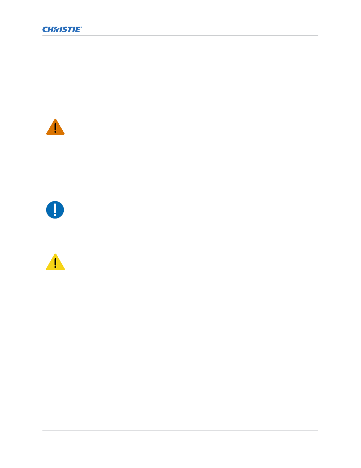
Warning! If not a
• Observe all electrostatic precautions. Use a grounded wrist strap and insulated tools when
handling, servicing, or cleaning electronic assemblies.
• A minimum of two people or appropriately rated lift equipment is required to safely lift, install,
or move the product.
• A certified electrician must be present during installation to ensure the installation meets the
local electrical code.
• Motors and fans may start without warning.
• SHOCK HAZARD! Power supply uses double pole/neutral fusing. Disconnect all power sources
before opening the product.
Notice. If not a
• Always wear clean, lint-free gloves when handling the product.
voided, the following could result in death or serious injury.
voided, the following could result in property damage.
AC power precautions
Learn the safet
y precautions related to AC power.
Caution! If not a
• SHOCK HAZARD! Disconnect the product from AC before installing, moving, servicing, cleaning,
removing components, or opening any enclosure.
• SHOCK HAZARD! Do not attempt operation if the AC supply is not within the specified voltage
and current, as specified on the license label.
• FIRE HAZARD! Do not use a power cord, harness, or cable that appears damaged.
• FIRE AND SHOCK HAZARD! Do not attempt operation unless the power cord, power socket, and
power plug meet the appropriate local rating standards.
voided, the following could result in minor or moderate injury.
MicroTiles LED Installation and Setup Guide 6
020-102825-04 R
Copyright © 2022 Christie Digital Systems USA, Inc. All rights reserved.
If printed, please recycle this document after use.
ev. 1 (07-2022)
Page 7
Product overview
Remote Power Rack Shelf safety warnings
T
o prevent personal injury and to protect the device from damage, read and follow these safety
precautions.
Warning! If not a
• Only Christie qualified technicians are permitted to open product enclosures.
• This product must be installed within a restricted access location not accessible by the general
public.
• SHOCK HAZARD! Disconnect the product from AC before installing, moving, servicing, cleaning,
removing components, or opening any enclosure.
• A minimum of two people or appropriately rated lift equipment is required to safely lift, install,
or move the product.
• A certified electrician must be present during installation to ensure the installation meets the
local electrical code.
• Install the product near an easily accessible AC receptacle.
• Hazardous voltages are present at power system inputs. The DC output, though not dangerous
in voltage, has a high short-circuit current capacity that may cause severe burns and electrical
arcing.
• SHOCK HAZARD! Power supply uses double pole/neutral fusing. Disconnect all power sources
before opening the product.
• Before working with live power systems, remove all metallic jewelry (such as watches, rings,
metal rimmed glasses, or necklaces) and wear safety glasses with side shields at all times during
the installation.
• Motors and fans may start without warning.
• Use insulated hand tools while working on live power systems.
voided, the following could result in death or serious injury.
Product labels
Learn about the labels that ma
black and white.
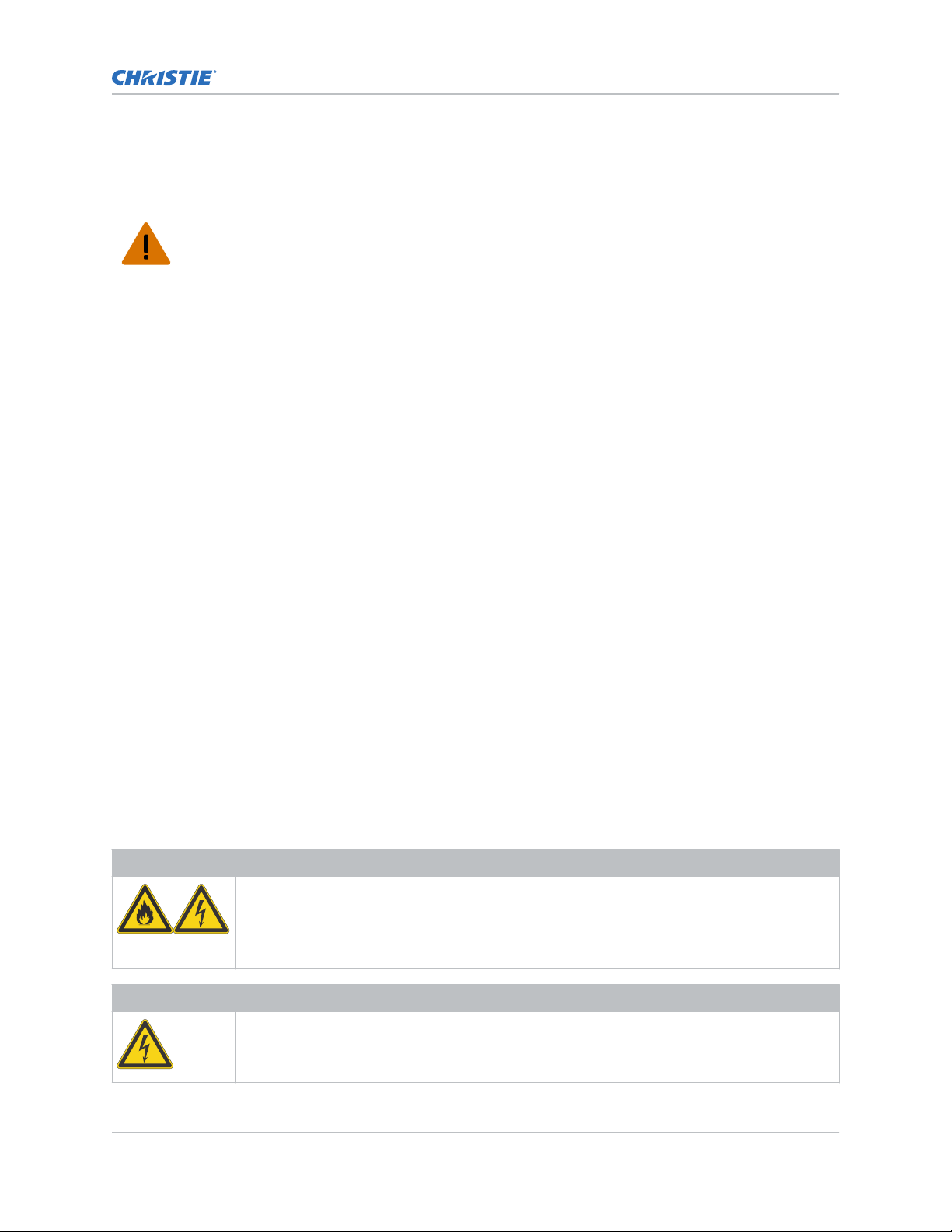
General hazards
Hazard warnings also apply to accessories once they are installed in a Christie product that is
connected to power.
Fire and Shock Hazard
To prevent fire or shock hazards, do not expose this product to rain or moisture.
Do not alter the power plug, o
Do not remove the product enclosure.
Only Christie qualified technicians are authorized to service the product.
Electrical Hazard
Risk of electric shock.
Do not remo
Only Christie qualified technicians are authorized to service the product.
MicroTiles LED Installation and Setup Guide 7
020-102825-04 R
Copyright © 2022 Christie Digital Systems USA, Inc. All rights reserved.
If printed, please recycle this document after use.
ev. 1 (07-2022)
y be used on the product. Labels on your product may be yellow or
verload the power outlet, or use it with extension cords.
ve the product enclosure.
Page 8
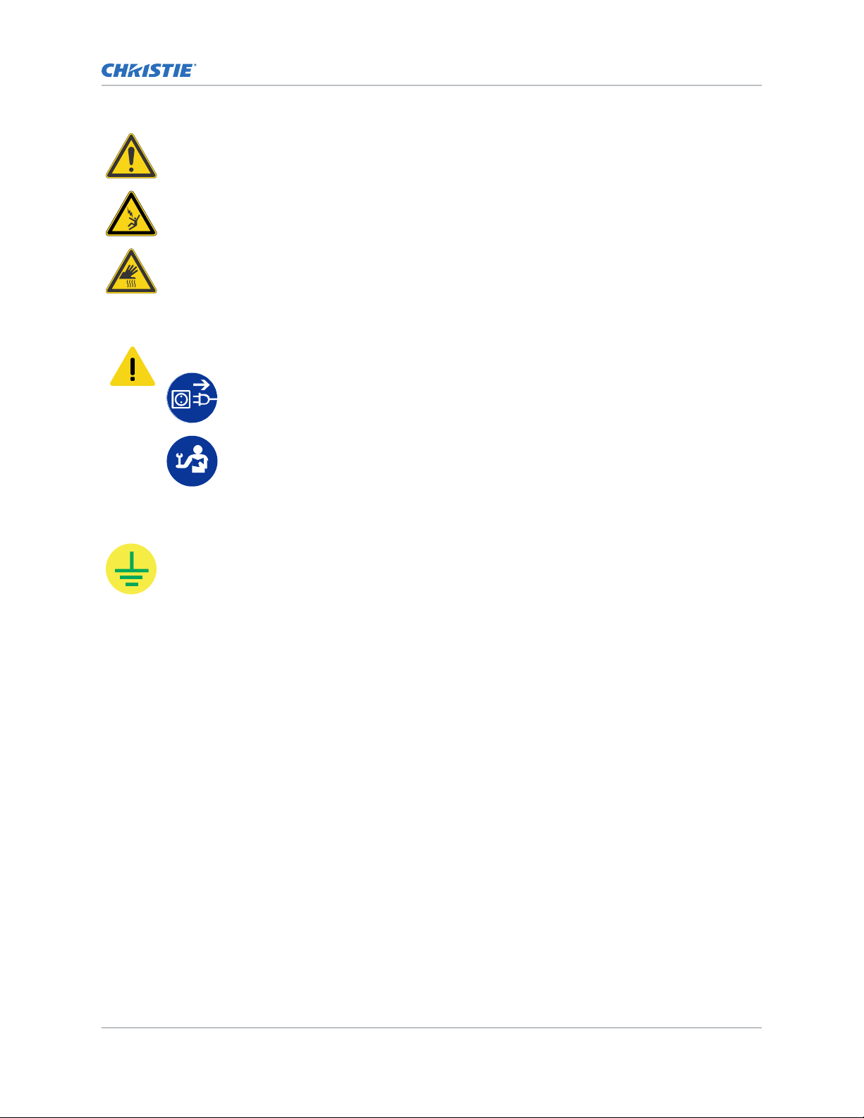
General hazard.
Electrocution hazard. To avoid personal injury, always disconnect all power sources before
performing maintenance or service procedures.
Burn hazard. To avoid personal injury, allow the product to cool for the recommended cool
down time before performing maintenance or service.
Mandatory action
Caution! If not a
Product overview
voided, the following could result in minor or moderate injury.
SHOCK HAZARD! Disconnect all power sources before performing maintenance or
service procedures.
Consult the service manual.
Electrical labels
Indicates the presence of an earth ground.
MicroTiles LED Installation and Setup Guide 8
020-102825-04 R
Copyright © 2022 Christie Digital Systems USA, Inc. All rights reserved.
If printed, please recycle this document after use.
ev. 1 (07-2022)
Page 9
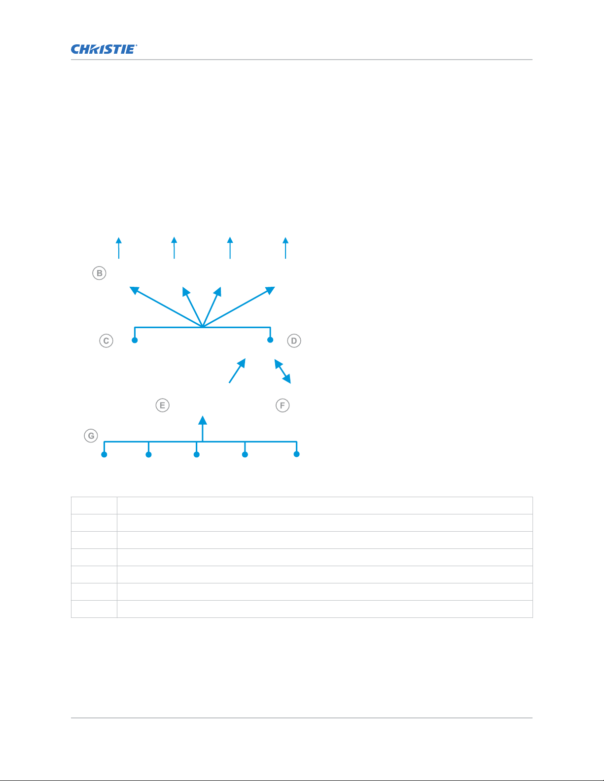
Typical MicroTiles LED solution
ypical MicroTiles LED installation contains a variety of components.
A t
Product overview
A LED tiles
B Octrollers—Each Octroller can control up to eight LED tiles.
C Remote Power Rack Shelf
D LED Wall Controller
E Video matrix switch and splicing video processor
F Control computer for accessing the web user interface (WebUI)
G Media sources
MicroTiles LED Installation and Setup Guide 9
020-102825-04 R
Copyright © 2022 Christie Digital Systems USA, Inc. All rights reserved.
If printed, please recycle this document after use.
ev. 1 (07-2022)
Page 10
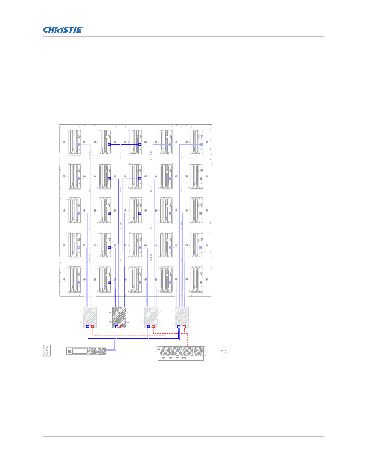
Cable and component layout and design
Product overview
Before an arr
ay is constructed, plan the design layout of the tiles to make sure that the controller
placement and the cabling layout support the overall tile design objectives.
The LED display system offers considerable flexibility in terms of the number of media sources that
can be displayed and the overall resolution. Color and brightness matching, as well as other functions,
may be performed across an entire array.
The video source connections between the components are represented by the blue line. The power
connections between the components are represented by the red line.
MicroTiles LED Installation and Setup Guide 10
020-102825-04 R
Copyright © 2022 Christie Digital Systems USA, Inc. All rights reserved.
If printed, please recycle this document after use.
ev. 1 (07-2022)
Page 11
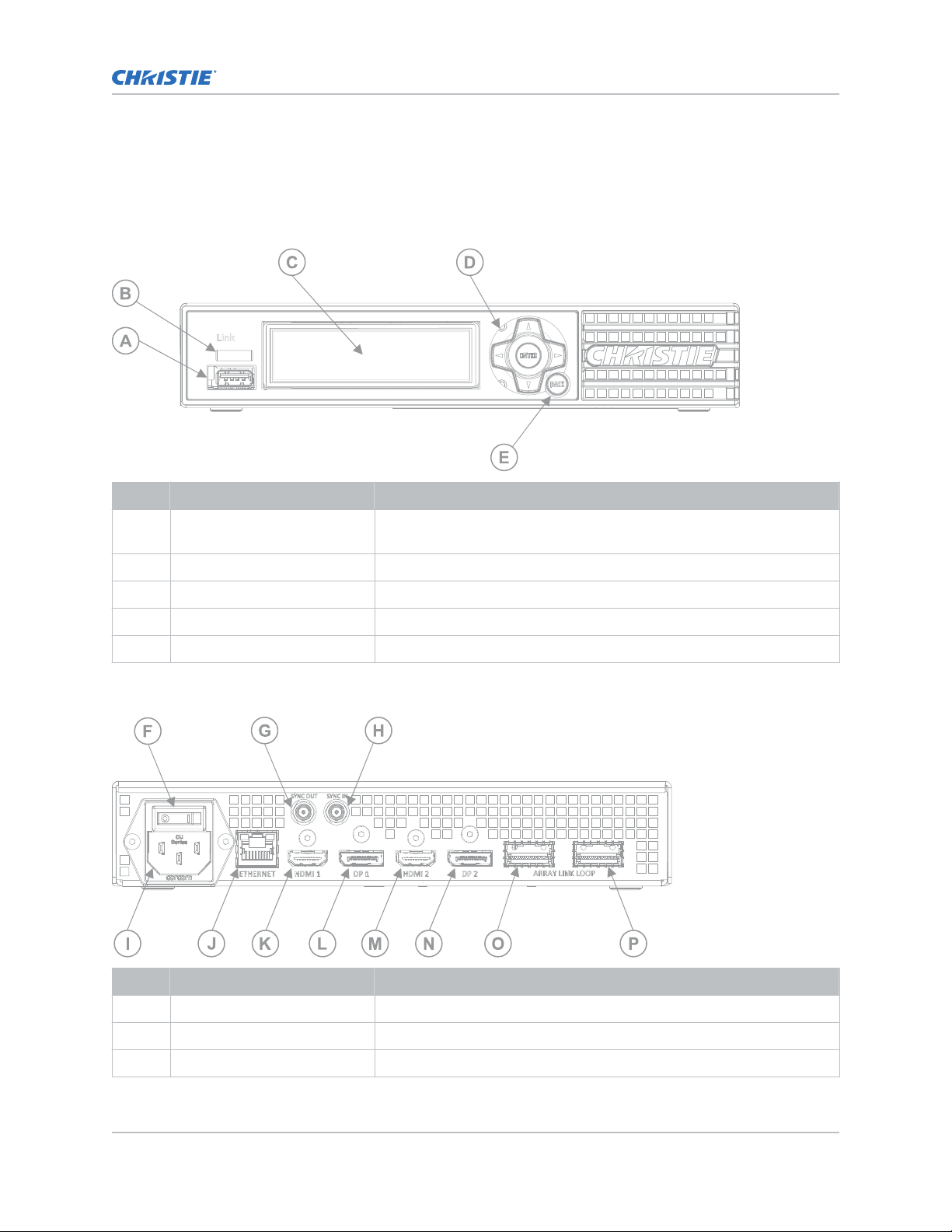
Wall controller interface and ports
Product overview
Learn about the interface and ph
ysical ports on the wall controllers.
Front ports
ID Component Description
A USB port Accepts USB storage devices for upgrade, interrogation, and USB to
serial adapter
B LED status indicator Indicates device status.
C Display panel Provides more detailed status and menu options/settings.
D Keypad Use the keypad to navigate through the menu options.
.
E Back button Exits the current menu option.
Christie Link E1000 rear ports
ID Component Description
F AC power switch Powers on and off the unit.
G Sync out (SMA connector) Reserved for future use.
H Sync in (SMA connector) Reserved for future use.
MicroTiles LED Installation and Setup Guide 11
020-102825-04 R
Copyright © 2022 Christie Digital Systems USA, Inc. All rights reserved.
If printed, please recycle this document after use.
ev. 1 (07-2022)
Page 12
Product overview
ID Component Description
I AC power receptacle Plug in an appropriately rated line cord.
J Ethernet Accepts an Ethernet cable connection.
K HDMI 1 High-Definition Multimedia Interface cable connection 1 (In only)
L DP1 Display Port connection 1 (In only)
M HDMI 2 High-Definition Multimedia Interface cable connection 2 (In only)
N DP2 Display Port connection 2 (In only)
O QSFP+0 Use this port to connect to Octrollers.
P QSFP+1 Use this port to connect to Octrollers.
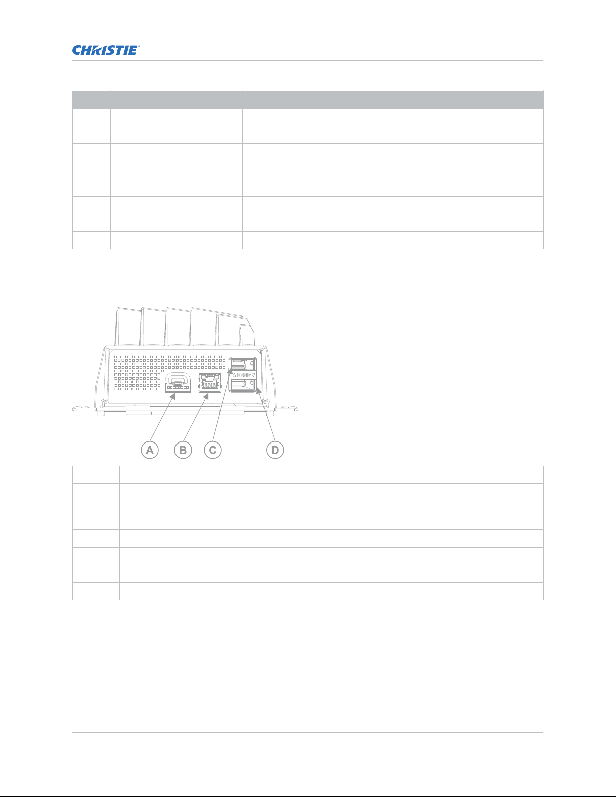
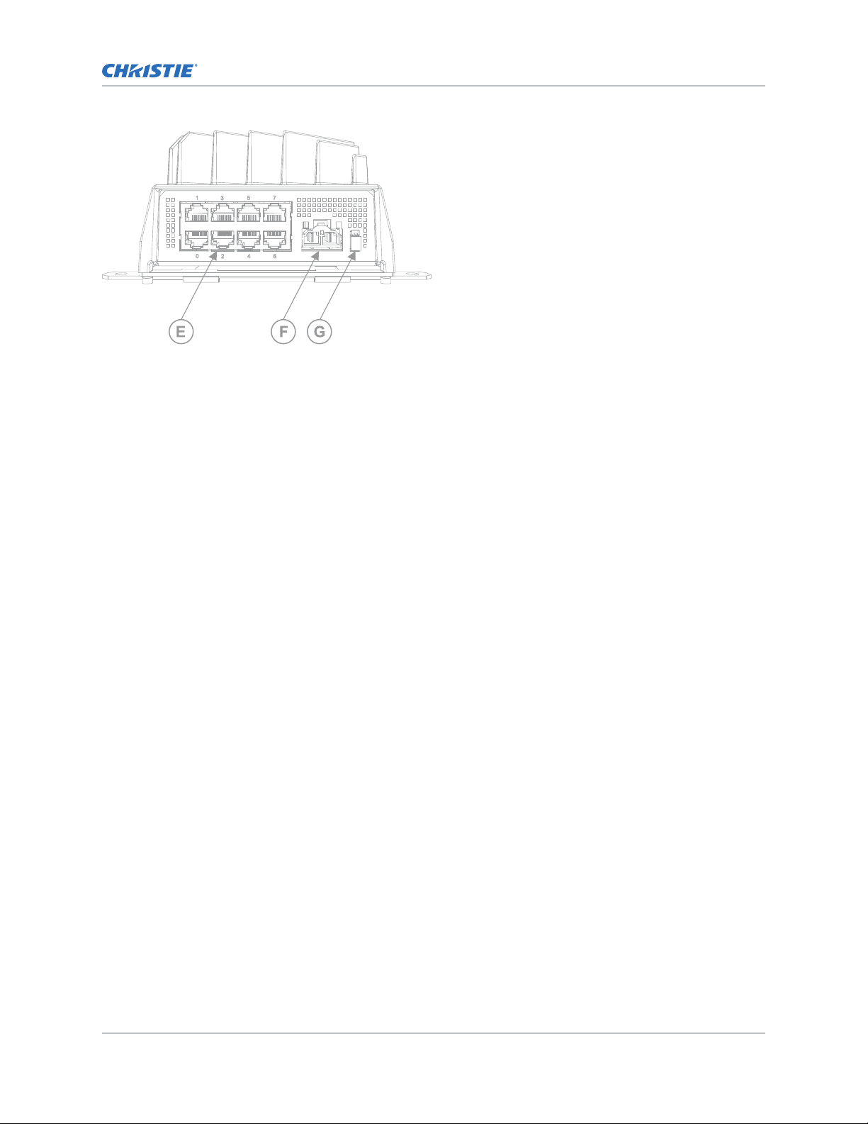
Octroller ports
Learn about the interface and ph
A Ambient light sensor and 3D sync signal for an external IR box.
B Service—To access serial commands and other service functionality, connect an Ethernet cable
between the Octroller and a computer.
C QSFP+0—Connection that sends data from the wall controller to all Octrollers in the chain.
D QSFP+1—Connection that sends data from the wall controller to all Octrollers in the chain.
E Tile Link—Sends power and data from the Octroller to the LED tiles. One connection per tile.
F DC power connection to the Remote Power Rack Shelf
ysical ports on the Octroller.
G PWR OK—Connects to the local AC power supply when used in a redundant configuration.
MicroTiles LED Installation and Setup Guide 12
020-102825-04 R
Copyright © 2022 Christie Digital Systems USA, Inc. All rights reserved.
If printed, please recycle this document after use.
ev. 1 (07-2022)
Page 13
Product overview
Technical support
T
echnical support for Christie Enterprise products is available at:
• North and South America: +1-800-221-8025 or [email protected]
• Europe, Middle East, and Africa: +44 (0) 1189 778111 or [email protected]
• Asia Pacific ([email protected]):
• Australia: +61 (0)7 3624 4888 or [email protected]
• China: +86 10 6561 0240 or [email protected]
• India: +91 (80) 6708 9999 or [email protected]
• Japan: 81-3-3599-7481
• Singapore: +65 6877-8737 or [email protected]
• South Korea: +82 2 702 1601 or [email protected]
• Christie Professional Services: +1-800-550-3061 or [email protected]
MicroTiles LED Installation and Setup Guide 13
020-102825-04 R
Copyright © 2022 Christie Digital Systems USA, Inc. All rights reserved.
If printed, please recycle this document after use.
ev. 1 (07-2022)
Page 14
Installation and setup
The configur
only. Before installing an LED array, you must fully understand all site requirements and
characteristics.
ation of an array depends on the installation. Use the following instructions as a guideline
Warning! If not a
• The supporting structure must safely support the combined load of the product, all attached
hardware, and components following all local safety standards and regulations.
• External support for a display wall must be designed and implemented by a Christie qualified
installer and must comply with local area regulations and safety standards.
• The area behind the MicroTiles LED tiles is a restricted access location not accessible by the
general public.
• Only personnel who are trained on the precautions for the restricted access location can be
granted entry to the area.
voided, the following could result in death or serious injury.
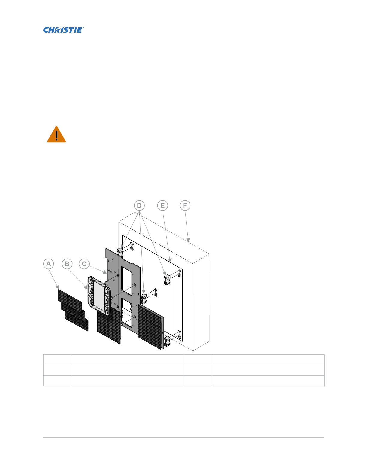
A LED modules D Wall anchors
B Chassis E Mounting template
C Mounting sheet F Structural mount surface
MicroTiles LED Installation and Setup Guide 14
020-102825-04 R
Copyright © 2022 Christie Digital Systems USA, Inc. All rights reserved.
If printed, please recycle this document after use.
ev. 1 (07-2022)
Page 15

Installation and setup
Installing the mounting sheets
Install the mounting sheets and tiles onto a support structure that can support the combined load of
the product and meets all local safet
Use these steps as a high-level workflow for installing the mounting sheets. For detailed instructions,
refer to the page identified in the step.
1. Using a laser level to project a plumb line, ensuring approximately 65mm is between the wall
surface and the laser line, measure the distance to the structural mounting surface in various
locations over the intended installation area.
If the variation over all measurements exceeds 15mm or 5/8", adjust the plumb line so all the
measurements to the wall are 15mm or less.
Make note of the location of the extreme variations in the wall depth. This will assist in
establishing a starting point when installing the mounting template.
2. In the bottom center of the array, level and attach the mounting template to the surface (on
page 15).
3. Install and level all remaining mounting templates for the array.
4. For the entire array, attach the magnetic anchors in the marked locations on the mounting
template (on page 17).
5. Install the screw anchors for the first mounting sheet.
6. Mount the sheet on the anchors (on page 17).
7. Install the adjacent mounting sheets in the array (on page 21).
8. After the sheets have been installed, adjust the wall to be flat (on page 19).
y standards and regulations.
Hanging the mounting template
Use two people to hang the mounting template. One mounting template provides guidance for two
sheets and multiple mounting anchors.
1. Ensure the wall is flat and there is less than 15mm or 5/8" difference in depth across the wall.
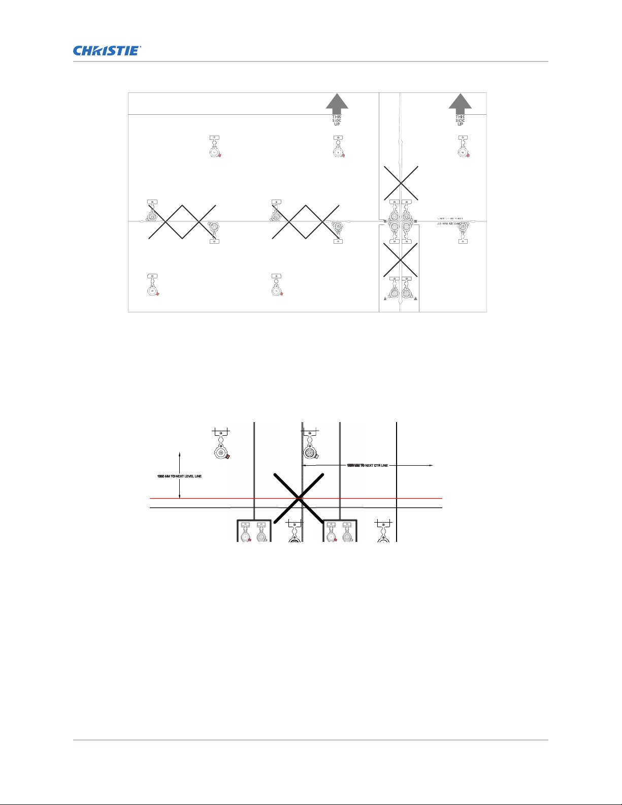
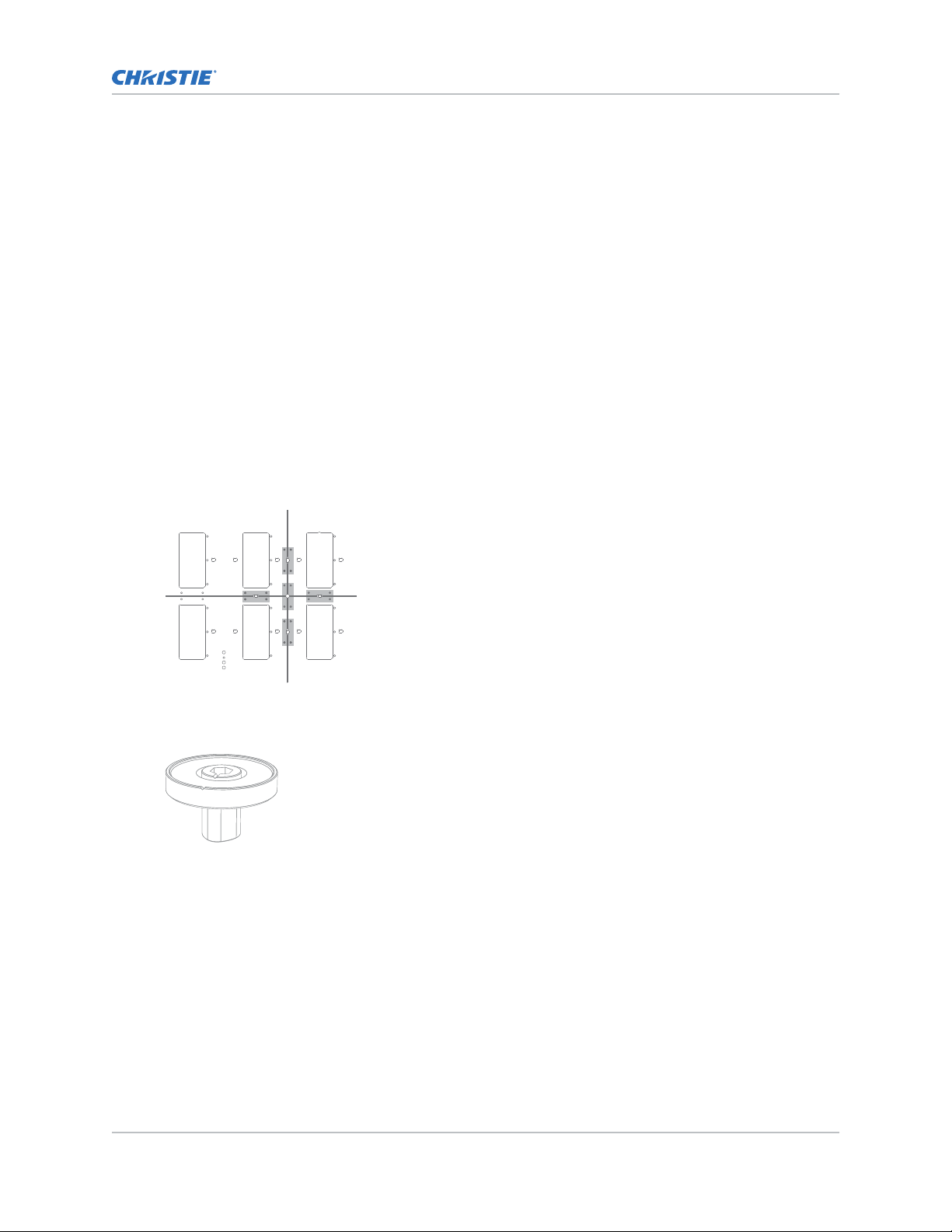
2. Locate the bottom center of the array and hang the first mounting template at this location so
the edge of the template aligns with the center of the array.
a) Orient the mounting template so all text is readable and not upside down.
b) Using a laser level, set a level and plumb line that intersects with the center line of the
anchor in the bottom left corner of the mounting template.
c) Adjust the mounting template so the cross hairs of the anchors at the horizontal and
vertical edges of the template are aligned to the level and plumb lines.
d) Affix the mounting template in place on the wall with staples or low-adhesive two-sided
tape.
Christie recommends putting the staples or adhesive tape close to the anchor locations on
the mounting template. This helps to keep the mounting template from lifting while drilling
pilot holes.
3. Install the adjacent mounting template.
a) Orient the mounting template so all text is readable.
b) Overlap the alignment markers (X) of the initial mounting template with the markers on
the adjacent mounting template.
MicroTiles LED Installation and Setup Guide 15
020-102825-04 R
Copyright © 2022 Christie Digital Systems USA, Inc. All rights reserved.
If printed, please recycle this document after use.
ev. 1 (07-2022)
Page 16
Installation and setup
c) Use a laser level to ensure the mounting template is level and to verify the anchor
mark
ers across two mounting templates are aligned.
d) Verify the mounting template is in the correct position, relative to the other mounting
templates.
• For new mounting templates in a column, measure the distance between the top of
the level line crosshair on one sheet and the top of the level line crosshair of the next
mounting template. The distance between the tops of each line should match the
distance indicated on the template (P/N: 020-103242-XX).
• For new mounting templates in a row, measure the distance between the right side of
the center line of the left mounting template and the right side of the center line of
the right mounting template. The distance between the center lines should match the
distance indicated on the template (P/N: 020-103242-
XX).
The other dimensions shown on the template can be used as a reference for
positioning and verifying the setup as required.
e) Affix the mounting template in place on the wall with staples or low-adhesive two-sided
tape.
MicroTiles LED Installation and Setup Guide 16
020-102825-04 R
Copyright © 2022 Christie Digital Systems USA, Inc. All rights reserved.
If printed, please recycle this document after use.
ev. 1 (07-2022)
Page 17
Installing the wall anchors
Installation and setup
Do not drop the anchors. Damage to the anchors ma
Notice. If not a
• Wear protective eyewear while drilling holes.
voided, the following could result in property damage.
y affect the anchor functionality.
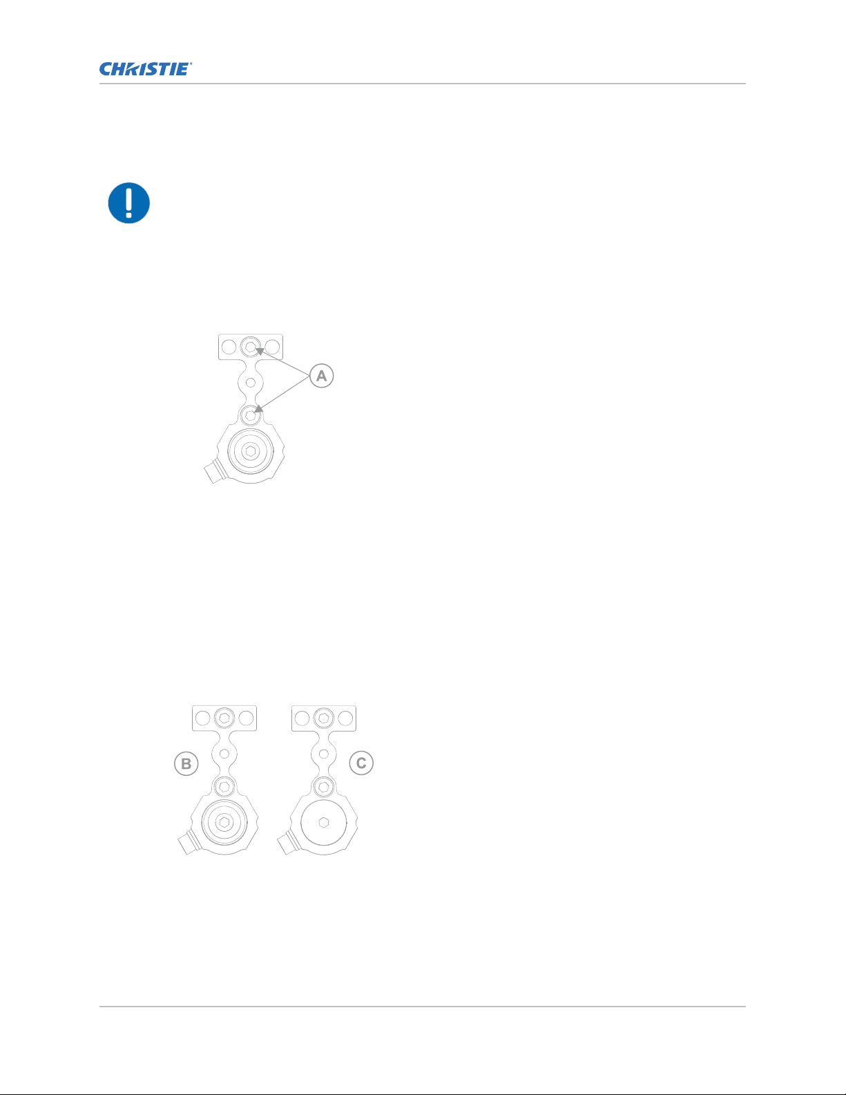
1. Prepare the mounting surface.
Smooth contiguous structural walls:
•
a. Using a 1/8 inch or 3 mm drill bit, pre-drill the mounting screw holes (A) for each
anchor location in the array.
Use the cross-hairs to locate the center of each anchor mount hole.
b. Place the anchor on the mounting template, ensuring the anchor is completely within
the anchor location outline.
•
For modular frame structures such as extrusion or Unistrut, the center of the internal
vertical members must be 240.1 mm apart. The distance between the closest internal
vertical and an edge vertical is approximately 219 mm but may vary based on the
installation.
2. Install the screws in the top and center of the anchor, securing the anchor to the surface.
Tighten the screws to 84 in-lb.
The anchors are designed to accommodate #12 wood screws, 6 mm machine screws, and ¼
inch machine screws.
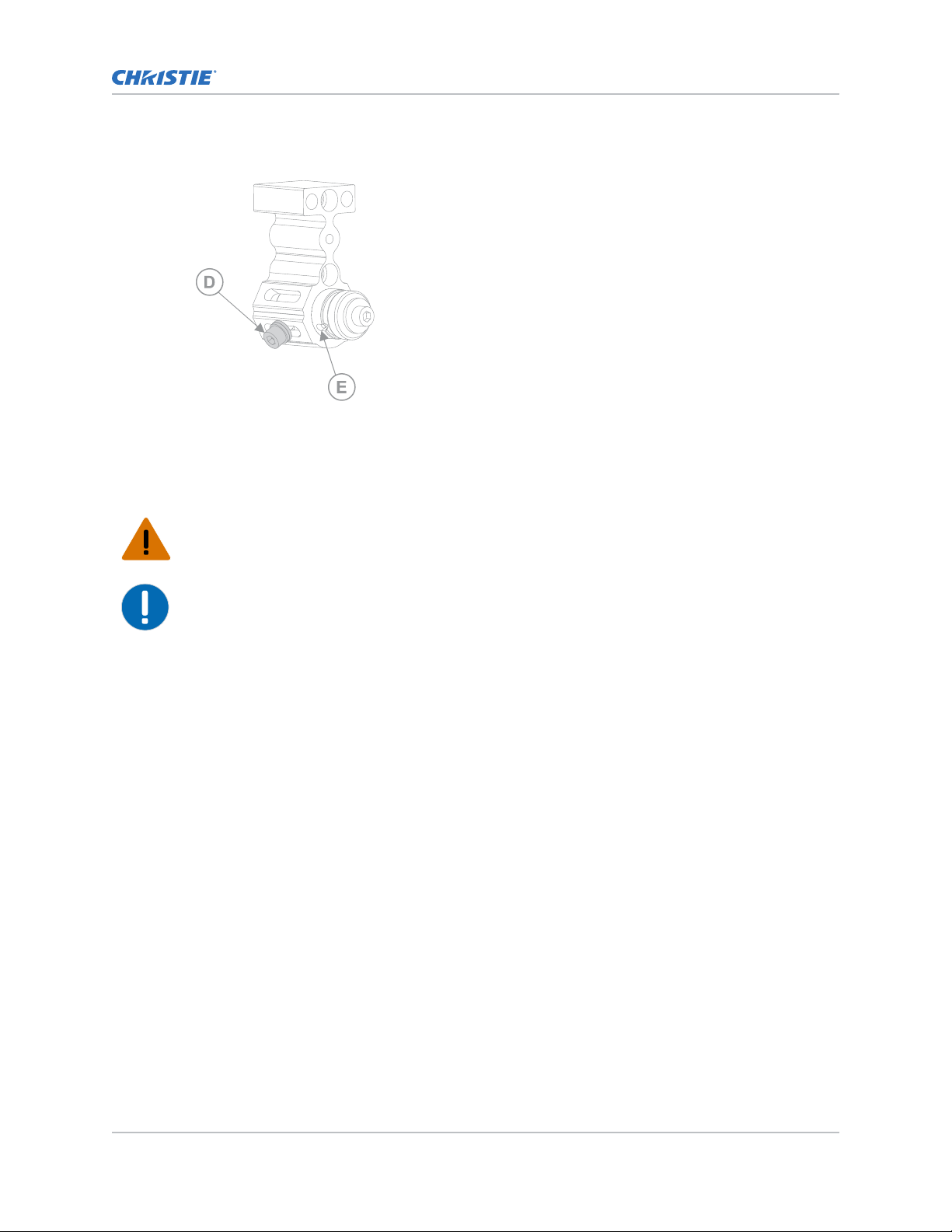
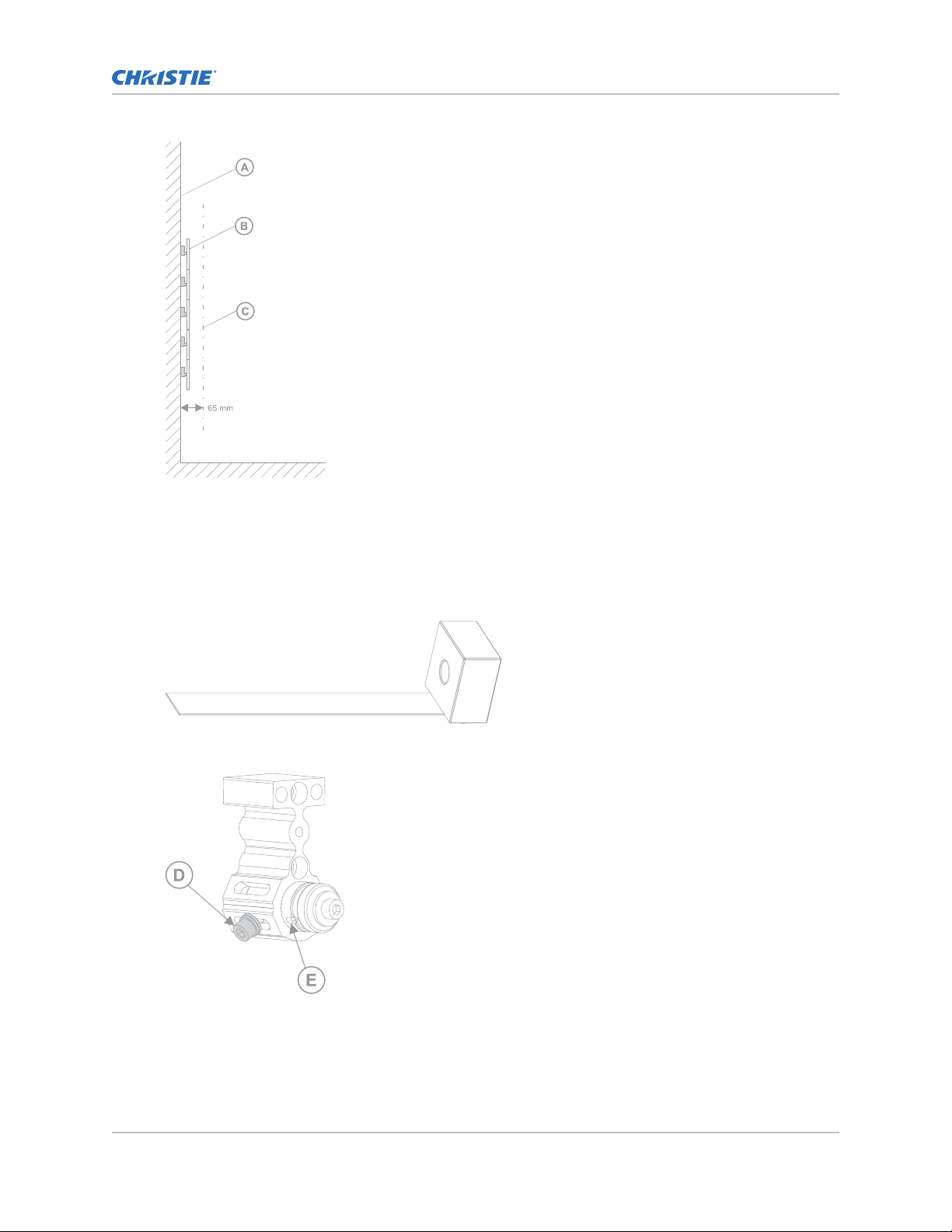
• Use the magnetic anchors (B) around the perimeter of the sheet location and the nonmagnetic anchors (C) for interior locations.
For anchors on the interior of the mounting sheet, the location of the adjustment screw
does not matter
.
• For anchors along the top of the array, rotate the anchor 180° so the T portion of the
anchor is to the interior of the array.
• For anchors along the sides of the array, relocate the adjustment screw (D) to the interior
of the array. To move the adjustment screw, remove the screw, and re-install it on the
MicroTiles LED Installation and Setup Guide 17
020-102825-04 R
Copyright © 2022 Christie Digital Systems USA, Inc. All rights reserved.
If printed, please recycle this document after use.
ev. 1 (07-2022)
Page 18
Installation and setup
opposite side of the anchor. The anchor shaft must be rotated until the hole in the shaft
(E) is aligned with the appropriate slot in the anchor body
.
3. Install the anchors at every location indicated on the mounting template.
Installing the metal mounting sheets
Keep the sheet as flat as possible. Do not bend or curve the sheet as it can impact the wall planarity.
Warning! If not a
• A minimum of two people or appropriately rated lift equipment is required to safely lift, install,
or move the product.
Notice. If not a
• Wear work gloves while handling the mounting sheet.
• Remove the paper wall template if regional or local building codes prohibit it.
voided, the following could result in death or serious injury.
voided, the following could result in property damage.
1. Locate the bottom center of the array.
2.
Remove the sheet from the packaging.
Wear work gloves while handling the mounting sheet.
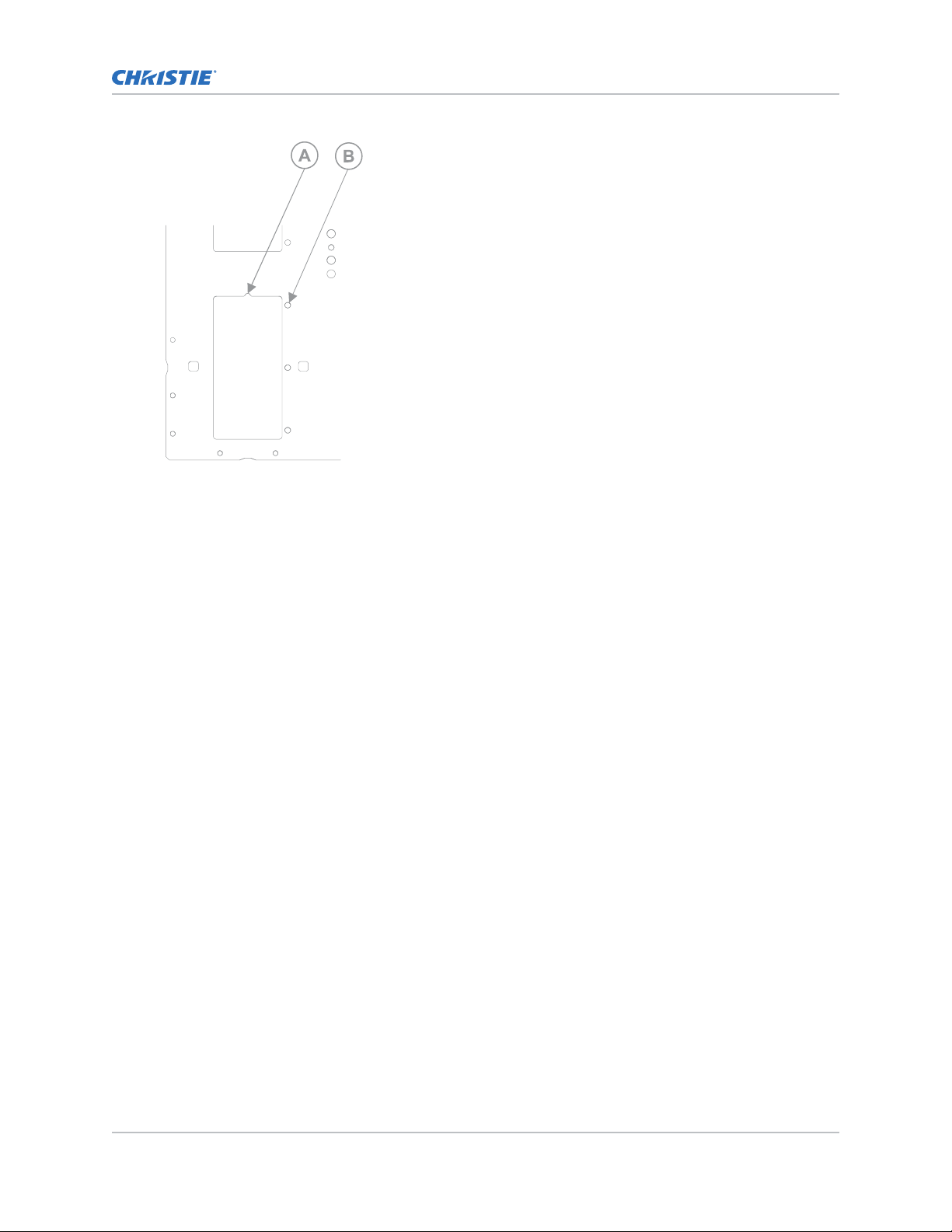
3. Turn the mounting sheet so the sheet orientation feature is at the top of the bottom left
chassis cut out (A) and the LED module tether holes are on the right side of the chassis cavity
(B).
MicroTiles LED Installation and Setup Guide 18
020-102825-04 R
Copyright © 2022 Christie Digital Systems USA, Inc. All rights reserved.
If printed, please recycle this document after use.
ev. 1 (07-2022)
Page 19
Installation and setup
4. With the assistance of another person, lift and attach the sheet onto the magnetic anchors.
The second person should continue to hold the sheet in place on the magnets until it is
secured.
5.
To secure the sheet to the anchors, install a washer and the M6 screw into the anchor. Finger
tighten the screw.
6. Using a laser level, square and level the sheet, ensuring the sheet holes are centered over the
anchor screw holes.
7. Install and fully tighten the washers and screws securing the sheet to the anchors to 84 in-lbs,
ensuring all holes are filled.
8. For the remaining sheets in the array, repeat step 2 to 7, keeping the screws hand tightened
until all leveling and adjusting is complete.
Adjusting the wall to be flat
To ensure the LED tiles install properly, adjust the mounting sheets to be flat.
During the Z plane adjustments of the wall, two screws must secure the mounting sheet to the
anchors at all times.
1. Set the laser level to be nominally parallel to the wall, ensuring approximately 65 mm is
between the wall surface and the laser line.
To make the distance consistent across the chassis plain, adjust the laser as needed.
MicroTiles LED Installation and Setup Guide 19
020-102825-04 R
Copyright © 2022 Christie Digital Systems USA, Inc. All rights reserved.
If printed, please recycle this document after use.
ev. 1 (07-2022)
Page 20
Installation and setup
2. Identify a point where the laser hits the tool and consistently use this point as the location
being analyz
ed while the wall is being adjusted.
The laser should hit this point anywhere on the wall.
Be sure to consistently reference the same edge of the laser line when aligning Z.
3. Locate the area of the wall that requires the most adjustment.
4. Place the magnetic block of the depth adjustment tool onto the sheet.
5. Slide the anchor adjustment screw (D) to extend or retract the anchor shaft until the sheet is
in a position where the laser hits the identified point on the tool.
6. When the adjustment on the anchor is complete, securely finger tighten the anchor adjustment
screw
.
MicroTiles LED Installation and Setup Guide 20
020-102825-04 R
Copyright © 2022 Christie Digital Systems USA, Inc. All rights reserved.
If printed, please recycle this document after use.
ev. 1 (07-2022)
Page 21
Installation and setup
If additional adjustments are required later, loosen the screw before adjusting the anchor. Slide
the anchor adjustment screw (D) to extend or retr
act the anchor shaft until the sheet is in a
position where the laser hits the identified point on the tool.
To achieve the needed adjustment, it may be necessary to loosen the surrounding anchors.
7. After the anchor is adjusted, mark the location on the metal sheet.
Marking an anchor as completed helps identify the anchors still requiring adjustments.
8. For all anchors in the array repeat steps 3 to 7.
To ensure the mounting sheets remain level and plumb, leave the laser level on during the
alignment of the entire wall.
9. After the entire wall is adjusted, fully tighten the anchor adjustment screws to 84 in-lbs.
Adjusting and leveling the mounting sheets
After installing and securing the metal mounting sheet, ensure they are level and verify the space
between the mounting sheets is correct.
1. From the rear of the installed sheet, attach the sheet couplers at all sheet alignment feature
locations on the edges where adjacent sheets are being installed with two M5 button head
screws.
Secure a minimum of two sheet couplers to each side. To allow for movement when the
adjacent sheet is installed, do not fully tighten the sheet coupler screws.
Insert the sheet locate tool into the hole on the sheet coupler.
2.
It may be necessary to adjust the sheets to allow space for the tool to be inserted.
3.
Turn the sheet locate tools so the notches on the top of the tool are pointing at the gap
between two mounting sheets.
4. On a side where two sheets meet, install the chassis on the two corners.
5. On one corner, install an LED module board at the edge of the sheet, and install the LED
module on the edge of the adjacent sheet.
6. If the second LED module is in danger of colliding with the first LED module, turn the sheet
locate tool to separate the sheets until the LED modules have 0.14 microns between them.
7. Tighten the screw closest to the edge of the sheet to hold the position of the sheet corner.
8. On the other corner of the sheet, repeat steps 2 to 7.
MicroTiles LED Installation and Setup Guide 21
020-102825-04 R
Copyright © 2022 Christie Digital Systems USA, Inc. All rights reserved.
If printed, please recycle this document after use.
ev. 1 (07-2022)
Page 22
Installation and setup
Adjusting one corner may shift the location of the opposite corner. To produce a level install, it
ma
y be necessary to re-adjust the corners.
9. When the new sheet is level, tighten all the sheet couplers to 84 in-lbs.
10. For each side of each sheet, repeat steps 1 to 9.
11. Repeat this procedure for all sheets in the array.
Installing and configuring the Remote Power Rack Shelf
Use the following instructions to install and configure the Remote Power Rack Shelf external power
supply.
Other 54 VDC power supplies (UL certified and SELV rated) may be used to power the Octrollers.
However, each Octroller must be protected with a 20 to 30 A maximum circuit breaker with a medium
trip delay. Alternate power systems must be reviewed and approved by Christie and by the local
electrical authority at the installation site.
Based on the power rack shelf type, the installation and configuration may be different. Refer the
Remote Power Rack Shelf User guide (P/N: 020-002027-XX) for the power shelf.
Mounting the Remote Power Rack Shelf
The power system must be mounted in a clean and dry environment. Sufficient free space must be
provided at the front and rear of the power system.
Warning! If not a
• This product must be installed within a restricted access location not accessible by the general
public.
1. Find a location in the rack for the Remote Power Rack Shelf.
2. Attach the Remote Power Rack Shelf to the rack.
To ensure a proper electrical bond between the system chassis and the relay rack use threadforming mounting screws and star washers.
voided, the following could result in death or serious injury.
Connecting the Octroller power cables to the Remote Power Rack Shelf
To power the Octrollers, connect the cables between the Octrollers and the Remote Power Rack Shelf.
Warning! If not a
• SHOCK HAZARD! Disconnect the product from AC before installing, moving, servicing, cleaning,
removing components, or opening any enclosure.
1. Ensure the Remote Power Rack Shelf breakers are off before connecting any cables to the
devices.
2.
Connect the main power cable to the Remote Power Rack Shelf.
3. Connect the other end of the main power cable to the Octroller.
If the main power cord supplied with your product is not long enough to connect the first
display panel in an array to the Remote Power Rack Shelf module, purchase a main power cord
of an adequate length. Christie recommends one of the pre-terminated power cables offered as
voided, the following could result in death or serious injury.
MicroTiles LED Installation and Setup Guide 22
020-102825-04 R
Copyright © 2022 Christie Digital Systems USA, Inc. All rights reserved.
If printed, please recycle this document after use.
ev. 1 (07-2022)
Page 23

Installation and setup
Christie accessories. Alternatively, create a custom cable using the Christie Main Power Cable
Spool (P/N 154-122106(P/N 154-124108-XX). For more information on the Molex Crimping Tool, see the Molex
documentation.
4. Plug the Remote Power Rack Shelf into the building outlets in the wall or the floor.
Each Remote Power Rack Shelf AC cable must be protected with its own circuit breaker. The
circuit breaker value should not exceed 20 A.
XX), Connector Kit (P/N 154-125109-XX), and Molex Crimping Tool
Resetting the breakers
When too many components are connected or too much power is sent through the Remote Power Rack
Shelf, the breakers may interrupt the current flow. Reset the breakers to resume operation.
If the breakers disconnect the current, the ON button is released for the affected Output.
1. Reduce the number of panels connected to the input or the amount of power going through the
input.
2. Push the ON button back into place.
The current is reconnected and the output is powered.
Installing the LED wall controller
The wall controller sends the input source signal to all Octrollers in the array.
1. Mount the LED wall controller.
The LED wall controller can be installed within 5 m of the wall when using a passive QSFP+
cable and up to 10 km away when using an active QSFP+ fiber cable.
2. Connect the LED wall controller to the building AC power supply.
3. On the LED wall controller, verify the power LED is green.
Powering on the array
Turn on each component in the array in the order below.
1. Start the computer that is the video source.
2. Turn on each rectifier in the Remote Power Rack Shelf.
As the wall is powering on, light flickers on the tiles.
3.
Wait for three to five minutes after powering on the rectifiers.
4. Turn on the LED wall controller.
MicroTiles LED Installation and Setup Guide 23
020-102825-04 R
Copyright © 2022 Christie Digital Systems USA, Inc. All rights reserved.
If printed, please recycle this document after use.
ev. 1 (07-2022)
Page 24

Mounting the Octroller
Installation and setup
Install the devices that send the source from the LED w
Caution! If not a
• This product must be installed within a restricted access location not accessible by the general
public.
• Only personnel who are trained on the precautions for the restricted access location can be
granted entry to the area.
1. Mount the Octroller.
Mount the
2. Connect the Octroller to the Remote Power Rack Shelf.
3. On the Octroller, verify the power LED is green.
4. For each Octroller in the array, repeat steps 1 to 3.
Octroller vertically with the 8x Ethernet connections at the top of the unit.
voided, the following could result in minor or moderate injury.
all controllers to the LED tiles.
Cabling the array
Connect the cables between all components of the array.
1. Connect cables from the source to the LED wall controller.
• For configurations with a single input, and no redundancy, connect the source cable to
DP1 or HDMI1.
• For configurations with two inputs creating a single image, connect source cables to both
DP 1 and DP 2, or HDMI 1 and HDMI 2.
The two input cables may be providing redundancy or for stitched content.
• For configurations displaying 3D content, connect the cable for the left eye source to DP/
HDMI 1 and connect the cable for the right eye source to DP/HDMI 2.
2. Using an appropriate length of QSFP cable, connect the cables from the LED wall controller to
the first Octroller.
Various lengths of this cable assembly are available from Christie.
3. Connect a QSFP+DAC cable between each Octroller in the array.
4. To create redundancy in the video signal, using an appropriate length of QSFP cable, connect
the cable from the last Octroller to the LED wall controller.
5. Hang one end of an Ethernet cable in the location on the mounting sheet where an LED tile will
be installed and connect the other end of the cable into an Octroller port.
To avoid an increase in temperature, where possible connect QSFP+ connectors into the lower
row of ports.
A maximum of eight LED tiles can be connected to a single Octroller.
Various lengths of CAT 6 unshielded, UTP, 24 AWG pre-terminated cables are available from
Christie. Alternatively, a custom length of Ethernet cable can be created using the Christie Cat
6 cable spool (P/N: 161-120104-XX), rJ45 Connect kit (P/N: 161-122106-XX) and Ethernet
crimping tool (P/N: 11-121105-XX).
6. For each tile in the array repeat step 5.
MicroTiles LED Installation and Setup Guide 24
020-102825-04 R
Copyright © 2022 Christie Digital Systems USA, Inc. All rights reserved.
If printed, please recycle this document after use.
ev. 1 (07-2022)
Page 25

Installation and setup
Installing the chassis and LED tiles
Mount the LED chassis and LED modules on the metal sheet.
The LEDs on the modules are fragile. Handle the LED modules with extreme care.
1. On the LED wall controller, display the Module ID using the ID menu.
2.
Connect the Ethernet cables to the LED chassis.
While the tiles are powering on, the LED flashes blue. After the tiles are fully powered on, the
LED is solid green.
3. Optionally, feed the tether through the sheet and chassis.
4. Set the chassis into the mounting sheet locations, lining up the locator pins in the chassis with
the mounting sheet locate features.
The magnets on the rear of the chassis securely snap the chassis onto the mounting sheet.
5. To ensure the chassis is seated properly, push the chassis down and to the left.
6. Check the web user interface to confirm Neighbor Detection is working.
When the detection is successful, the web user interface displays the correct tile layout grid.
7. In the web user interface, to start the automatic tile mapping, select Auto Map.
Christie recommends automatically mapping the tiles in the array after the chassis are
installed, and after the LED tiles are installed on the chassis.
8. Optional, attach the tether to the LED module.
9. Set the LED modules onto the chassis.
Be aware of adjacent, already installed module boards. If the LED modules appear to be
overlapping, alignment issues exist. Stop installing LED modules until the surrounding chassis
are located into the correct position and the overlap is resolved.
As each LED module is installed on the chassis, check for damaged or missing LEDs. If any
LEDs are non-functioning, replace the LED module.
10. In the web user interface, to start the automatic tile mapping, select Auto Map.
Related information
Accessing the MicroTiles LED web user interface (on page 27)
Securing the LED modules (on page 26)
Removing LED modules (on page 26)
Displaying a test pattern (on page 25)
Displaying a test pattern
Display a test pattern to help configure MicroTiles LED.
1. Log into the web user interface.
2. Select Test Pattern Generator.
3. From the Test Pattern window, select a test pattern.
To close the Test Pattern window, select Test Pattern Generator again.
4.
5. To turn off the test pattern, select Off.
MicroTiles LED Installation and Setup Guide 25
020-102825-04 R
Copyright © 2022 Christie Digital Systems USA, Inc. All rights reserved.
If printed, please recycle this document after use.
ev. 1 (07-2022)
Page 26
Removing LED modules
Installation and setup
When remo
1. Place the screen removal tool over the LED module board, pressing it firmly in place.
2. Hold the other module boards attached to the same chassis in place and pull the LED module
3. To remove the tool from the led module, roll the removal tool adhesive off the module.
4. If present, remove the tether from the back of the LED module board (on page 26).
Related information
Securing the LED modules (on page 26)
ving the LED modules, take care to not damage the LEDs.
away from the chassis.
To avoid damaging the surrounding LED modules, avoid rotating or pivoting the tool and
module.
Securing the LED modules
Learn how to secure the LED modules to the chassis and mounting sheet.
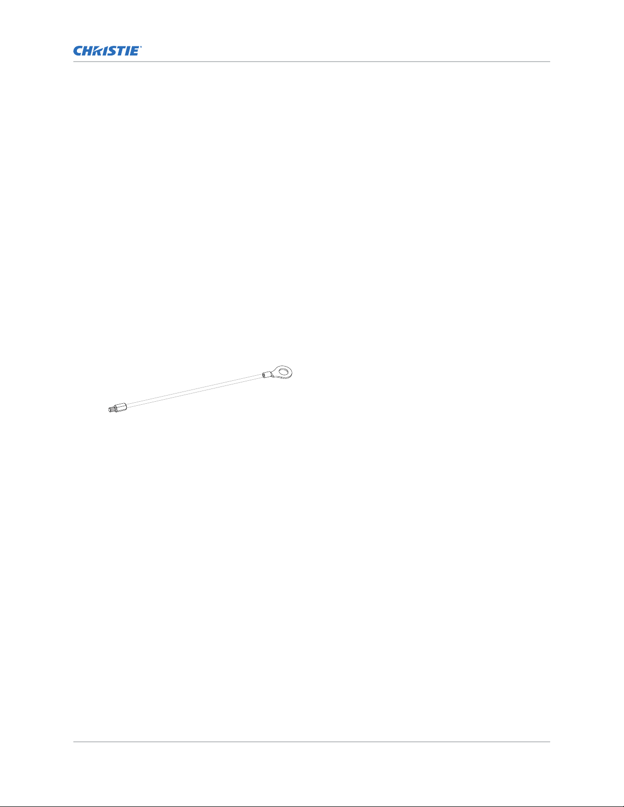
1. Reaching through a hole in the mounting sheet, insert a tether cable through the security
holes, the chassis, and into the LED module.
2. Tighten the tether screw.
3. For each LED module in the tile repeat steps 1 and 2.
MicroTiles LED Installation and Setup Guide 26
020-102825-04 R
Copyright © 2022 Christie Digital Systems USA, Inc. All rights reserved.
If printed, please recycle this document after use.
ev. 1 (07-2022)
Page 27

Verifying the hardware installation
Installation and setup
Using the web user interface mak
1. On the Dashboard, verify the correct number of hardware components in the array are listed.
2. On the Dashboard, verify the array link is a closed loop.
3. Make sure all chassis have identified their neighbors in the array.
a) Switch to the Canvas Editor.
b) Verify the canvas appears in the same shape as the installed array.
e sure the hardware is installed and recognized.
Accessing the MicroTiles LED web user interface
Learn how to access the web user interface.
The MicroTiles LED web user interface is supported on the following browsers:
• Google Chrome
• Microsoft Edge
• Safari
Access the web user interface to configure the array and monitor the status of the components.
1. In a web browser, type the IP address of the LED wall controller.
The IP address is displayed on the LED wall controller display.
In configurations with two LED wall controllers, entering the IP address for either wall
controller accesses the same web user interface settings.
2. Log into the session with the user name and the password.
The user name and password are case-sensitive.
3. Select Login.
Setting up MicroTiles LED for 3D
MicroTiles LED is capable of displaying stereoscopic 3D video sources, relying on additional hardware
(stereo emitters and glasses) to complete the display system.
3D is only available on 1.25mm tiles.
Images generated from a stereo 3D video source consist of a series of images (frames) that alternate
quickly between two slightly different viewpoints, corresponding to our left and right ey
frames are displayed fast enough and viewed with special glasses synchronized to the left/right (L/R)
changes, the resulting image appears with the same depth and perspective sense in the real world.
MicroTiles LED uses a dual-input configuration for displaying 3D content, where two video streams are
provided by the video server, with the left eye supplied by one stream and the right eye supplied by
the other. The video streams are frame locked and supplied concurrently.
MicroTiles LED Installation and Setup Guide 27
020-102825-04 R
Copyright © 2022 Christie Digital Systems USA, Inc. All rights reserved.
If printed, please recycle this document after use.
ev. 1 (07-2022)
es. When these
Page 28
3D requirements
Installation and setup
Stereo 3D applications require a stereo 3D-capable source, special hardw
the array's 3D Settings menu option to control the processing, synchronization, and displaying of the
stereoscopic 3D source material.
are and software setups, and
Hardware requirements
Understand the hardware requirements for stereo 3D applications.
• E1000-3D wall controller (P/N: 161-012104-XX)
• 3D sync cable
• AE125H IR External 3D Emitter for controlling active shutter glasses
• XPAND Vision X101 3D glasses
• A source, usually a computer with a 3D graphics card(s)
Software and content requirements
Understand the software and content requirements for stereo 3D applications.
• Any 3D computer software that supports 3D stereo on a supported computer(s) with
associated graphic cards (suggested cards include ATI or NVIDIA)
• A video stream from a video source prepared to be sequential content (for direct-input 3D) or
two video streams from a video source that has been prepared to be supplied left eye and
right eye concurrently and frame locked (dual-input 3D)
Active stereo 3D configuration
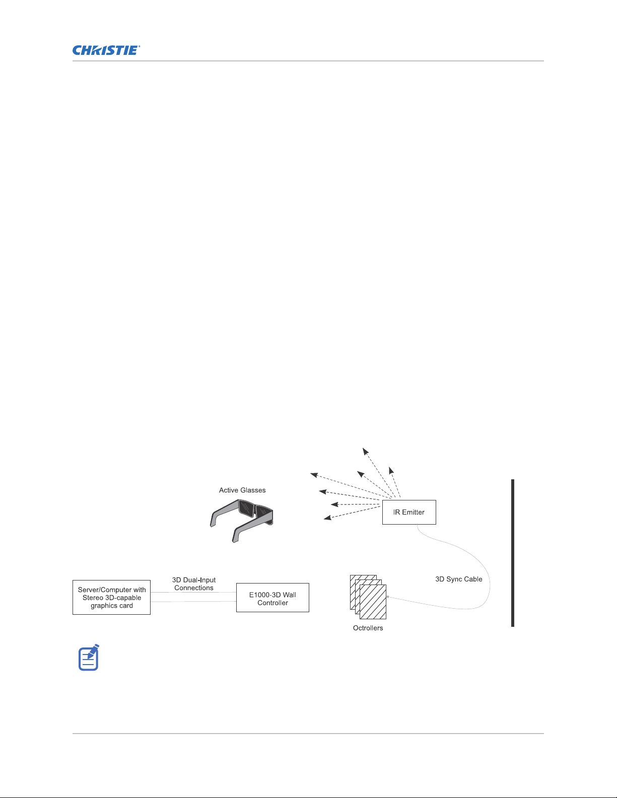
Use the following diagram to understand a typical hardware configuration for active stereo 3D
systems.
In response to the 3D Sync Out signal from the array, the IR emitter emits an infrared signal to a
er in the active 3D shutter glasses. This synchronizes the active glasses to alternatively open and
receiv
close for the active stereo 3D applications.
MicroTiles LED Installation and Setup Guide 28
020-102825-04 R
Copyright © 2022 Christie Digital Systems USA, Inc. All rights reserved.
If printed, please recycle this document after use.
ev. 1 (07-2022)
Page 29

Cabling the array
Installation and setup
Connect the cables between all components of the arr
ay.
1. Connect cables from the source to the LED wall controller.
• For configurations with a single input, and no redundancy, connect the source cable to
DP1 or HDMI1.
• For configurations with two inputs creating a single image, connect source cables to both
DP 1 and DP 2, or HDMI 1 and HDMI 2.
The two input cables may be providing redundancy or for stitched content.
• For configurations displaying 3D content, connect the cable for the left eye source to DP/
HDMI 1 and connect the cable for the right eye source to DP/HDMI 2.
2. Using an appropriate length of QSFP cable, connect the cables from the LED wall controller to
the first Octroller.
Various lengths of this cable assembly are available from Christie.
3. Connect a QSFP+DAC cable between each Octroller in the array.
4. To create redundancy in the video signal, using an appropriate length of QSFP cable, connect
the cable from the last Octroller to the LED wall controller.
5. Hang one end of an Ethernet cable in the location on the mounting sheet where an LED tile will
be installed and connect the other end of the cable into an Octroller port.
To avoid an increase in temperature, where possible connect QSFP+ connectors into the lower
row of ports.
A maximum of eight LED tiles can be connected to a single Octroller.
Various lengths of CAT 6 unshielded, UTP, 24 AWG pre-terminated cables are available from
Christie. Alternatively, a custom length of Ethernet cable can be created using the Christie Cat
6 cable spool (P/N: 161-120104-XX), rJ45 Connect kit (P/N: 161-122106-XX) and Ethernet
crimping tool (P/N: 11-121105-XX).
6. For each tile in the array repeat step 5.
Enabling 3D
Install and configure the array to display 3D content.
1. To enable 3D for dual-input 3D content:
a) Install the array components as specified (on page 15), using the E1000-3D wall
controller.
b) Cable the array, connecting the cable for the left eye source to HDMI or DP 1, and the
right eye source cable to input 2.
c) Install the IR emitter.
d) Connect the 3D sync cable between the IR emitter and the service port on any Octroller.
e) In the web user interface, select Input Selection.
f) Select DP Dual Input 3D or HDMI Dual Input 3D as appropriate.
2. To enable 3D for a single, frame-sequential 3D video input:
a) Install the array components as specified (on page 15), using the E1000-3D wall
controller.
b) Configure the array for a single input (on page 31).
MicroTiles LED Installation and Setup Guide 29
020-102825-04 R
Copyright © 2022 Christie Digital Systems USA, Inc. All rights reserved.
If printed, please recycle this document after use.
ev. 1 (07-2022)
Page 30

Installation and setup
c) Install the IR emitter.
d)
Connect the 3D sync cable between the IR emitter and the service port on any Octroller.
e) In the web user interface, select Input Selection.
f) Change the 3D sync delay to 7700.
g) In the 3D Settings area select Enable 3D stereo in a single port.
Disposing of the product packaging
Once the product has been installed and set up, Christie recommends reusing or recycling the product
packaging according to your local regulations.
MicroTiles LED Installation and Setup Guide 30
020-102825-04 R
Copyright © 2022 Christie Digital Systems USA, Inc. All rights reserved.
If printed, please recycle this document after use.
ev. 1 (07-2022)
Page 31
Completing the initial configuration
After installing the tiles and connecting all cables, complete the initial configur
For additional configuration settings, refer to MicroTiles LED User Guide (P/N: 020-102835-XX).
ation.
Automatically mapping tiles in the array
MicroTiles LED tiles are equipped with neighbor detection, which automatically determines the location
of each tile within the canvas and the overall configuration of the canvas.
Christie recommends automatically mapping the tiles in the array after the chassis are installed, and
after the LED tiles are installed on the chassis.
1. Select Canvas Editor.
2. Under the Array Properties tab, select Auto Map Tile Location.
All devices in the array are renumbered. The Octrollers are renumbered based on their
connection order from the primary wall controller. Tiles are renumbered, row by row, with tile 1
located at the top left corner.
3. To view the tile edges that have been located, select Identify Tiles
Neighbor Detection test pattern.
An
y edges where a neighbor has not been detected appear as red lines. Edges where
neighbors have been detected are black. To update the results displayed, re-apply the test
pattern.
and display the
Selecting the input
Configure the input for an array with one or more LED wall controllers.
1. Log into the MicroTiles LED web user interface.
2. Select Input Selection.
3. In the Device List, select the LED wall controller.
4. In the properties area, specify this is the Primary Controller.
5. Configure the input.
• E1000 wall controller
a. Select the input.
• Disable—Disables displaying content on the array.
• DP 1 or DP 2—Provides content to the LED wall controller through the
DisplayPort input.
MicroTiles LED Installation and Setup Guide 31
020-102825-04 R
Copyright © 2022 Christie Digital Systems USA, Inc. All rights reserved.
If printed, please recycle this document after use.
ev. 1 (07-2022)
Page 32

Completing the initial configuration
• HDMI 1
HDMI input.
• DP Stitched or HDMI Stitched—Splits content to the LED wall controller across
the two DP or HDMI inputs, where each input is providing half of the video. The
two inputs are stitched together, displaying the content as a single video.
Input 1 populates the left half of the array, and Input 2 populates the right. Both
signals must have identical timing.
b. If the second HDMI or DP port is going to provide redundancy for the content going
through HDMI 1 or DP 1, select Set [input name] as redundant.
• E1000-3D wall controller
a. Select the input.
• Disable—Disables displaying content on the array.
• DP 1 or DP 2—Provides content to the LED wall controller through the
DisplayPort input.
• HDMI 1 or HDMI 2—Provides content to the LED wall controller through the
HDMI input.
• DP Stitched or HDMI Stitched—Splits content to the LED wall controller across
the two DP or HDMI inputs, where each input is providing half of the video. The
two inputs are stitched together, displaying the content as a single video.
Input 1 populates the left half of the array, and Input 2 populates the right. Both
signals must have identical timing.
• DP Dual Input 3D or HDMI Dual Input 3D—Displays 3D content on the LED
array.
b. If the second HDMI or DP port is going to provide redundancy for the content going
through HDMI 1 or DP 1, select Set [input name] as redundant.
The array diagram is updated to reflect the input selection.
6. For an additional LED wall controller, select it from the device tree.
7. Set the wall controller as Secondary Controller.
By default, the second wall controller provides redundancy for the primary wall controller.
8. To configure the secondary wall controller, repeat step 5.
or HDMI 2—Provides content to the LED wall controller through the
Adjusting the brightness levels of the seams between tiles
To blend tiles together, change the brightness of the seam between the tiles or LED modules. The
brightness of each LED module seam can be adjusted.
1. From the ID list, display the Module ID test pattern.
2. Select Seam Correction.
3. Select the seams to adjust.
• To select a single seam, select the grey bar.
• To select the seams in an area of the array, or to select the entire array, click and drag the
mouse on a diagonal around the seams.
MicroTiles LED Installation and Setup Guide 32
020-102825-04 R
Copyright © 2022 Christie Digital Systems USA, Inc. All rights reserved.
If printed, please recycle this document after use.
ev. 1 (07-2022)
Page 33

Completing the initial configuration
• To select multiple seams, select CTRL and select each seam to be adjusted.
•
To select the entire array, click and drag the mouse on a diagonal around all tiles in the
array.
When multiple seams are selected, changing the brightness adjusts them to the same value.
4. To change the seam brightness, move the Seam Brightness slider or change the value in the
brightness percentage field.
MicroTiles LED Installation and Setup Guide 33
020-102825-04 R
Copyright © 2022 Christie Digital Systems USA, Inc. All rights reserved.
If printed, please recycle this document after use.
ev. 1 (07-2022)
Page 34

Regulatory
This product conforms to the latest regulations and standards related to product safet
environmental, and electromagnetic compatibility (EMC) requirements.
y,
Safety
• ANSI/UL 60950-1-2007 – Information Technology Equipment – Safety – Part 1: General
Requirements
• CAN/CSA C22.2 No. 60950-1-07 – Information Technology Equipment – Safety – Part 1:
General Requirements
• CAN/CSA-C22.2 No. 62368-1: 2014 (2nd Edition) – Audio/video, information and
communication technology equipment - Part 1: Safety requirements.
• EN 60950:2006 + A11:2009 + A1:2010 + A12:2011 + A2:2013 – Information Technology
Equipment – Safety – Part 1: General Requirements
• EN 62471:2008 (First Edition) – Photobiological Safety of Lamps and Lamp Systems
• IEC 60950-1:2005 (2nd Edition); + Amendment 1:2009 + Amendment 2:2013 – Information
Technology Equipment - Safety - Part 1: General Requirements
• IEC/EN 62368-1: 2014 (2nd Edition) – Audio Video, IT & Communication Technology
Equipment (AV/ICT) – Part 1: Safety Requirements.
• IEC 62471:2006 (First Edition) – Photobiological Safety of Lamps and Lamp Systems
• UL 62368-1: 2014 (2nd Edition) – Audio/video, information and communication technology
equipment - Part 1: Safety requirements.
Electro-magnetic compatibility
Emissions
• CAN ICES-003 (A)/NMB-003 (A) – Information Technology Equipment (Including Digital
Apparatus) – Limits and Methods of Measurement
• CISPR 32:2012/EN 55032:2012, Class A – Electromagnetic Compatibility of Multimedia
Equipment – Emission Requirements
• FCC CFR47, Part 15, Subpart B, Class A – Unintentional Radiators
• IEC 61000-3-2/EN61000-3-2: Limits for Harmonic Current Emissions
• IEC 61000-3-3/EN61000-3-3: Limitations of Voltage Changes, Voltage Fluctuations, and Flicker
MicroTiles LED Installation and Setup Guide 34
020-102825-04 R
Copyright © 2022 Christie Digital Systems USA, Inc. All rights reserved.
If printed, please recycle this document after use.
ev. 1 (07-2022)
Page 35

Regulatory
Immunity
•
CISPR 24:2010/EN55024:2010 EMC Requirements – Information Technology Equipment –
Immunity Characteristics – Limits and Methods of Measurements
Environmental
• China Ministry of Information Industry (along with 7 other Government Agencies) Order No.32
(01/2016) on the control of pollution caused by electronic information products, hazardous
substances concentration limits (GB/T 26572 - 2011), and the applicable product marking
requirement (SJ/T 11364 - 2014).
• EU Directive (2011/65/EU) on the restriction of the uses of certain hazardous substances
(RoHS) in electrical and electronic equipment and the applicable official amendment(s).
• EU Directive (2012/19/EU) on waste and electrical and electronic equipment (WEEE) and the
applicable official amendment(s).
• Regulation (EC) No. 1907/2006 on the registration, evaluation, authorization and restriction of
chemicals (REACH) and the applicable official amendment(s).
MicroTiles LED Installation and Setup Guide 35
020-102825-04 R
Copyright © 2022 Christie Digital Systems USA, Inc. All rights reserved.
If printed, please recycle this document after use.
ev. 1 (07-2022)
Page 36

 Loading...