

Christie GraphXMASTER RPMS-D100U, GraphXMASTER CS50-D100U, GraphXMASTER CS70-D100U, GraphXMASTER RPMS-D100UF, GraphXMASTER CS70-D100UF User Manual

RPMS-D100U/UF,
CS50-D100U & CS70-D100U/UF
User’s Manual
1 INTRODUCTION
2 SOURCE SETUPS
3 OPERATION
4 MAINTENANCE &
TROUBLESHOOTING
Table of Contents
Contents Page
1.1 Product Overview.......................................................................................1-1
1.2 Components................................................................................................1-2
1.3 Purchase Record and Servicing..................................................................1-2
2.1 Introduction ................................................................................................2-1
2.2 Source Connections.................................................................................... 2-1
2.3 Serial Port Connections.............................................................................. 2-8
2.4 Power Connection.....................................................................................2-10
2.5 Keypad Protocol....................................................................................... 2-10
3.1 Introduction ................................................................................................3-1
3.2 Projector Basics..........................................................................................3-1
3.3 Using the Keypad .......................................................................................3-3
3.4 Navigating the Menus................................................................................. 3-8
3.5 Using Inputs and Channels.......................................................................3-12
3.6 Adjusting an Image................................................................................... 3-18
3.7 System Configuration...............................................................................3-35
3.8 System Communications ..........................................................................3-40
3.9 System Status ........................................................................................... 3-43
3.10 Auto Setup.............................................................................................. 3-43
3.11 The Lamp Menu ....................................................................................3-44
3.12 Using Multiple Projectors.......................................................................3-48
3.13 Error Conditions..................................................................................... 3-54
4.1 Warning and Guidelines.............................................................................4-1
4.2 Cleaning and Maintenance .........................................................................4-3
4.3 Replacing Keypad Batteries.......................................................................4-5
4.4 Lamp Replacement.....................................................................................4-5
4.5 Troubleshooting........................................................................................ 4-10
5 SPECIFICATIONS
APPENDICES
NOTE: Due to constant research, the information in this manual is subject to change without notice
54-017188-05P RPMS, CS50 & CS70 User’s Manual
5.1 Specifications ............................................................................................. 5-1
Appendix A: Glossary..................................................................................... A-1
Appendix B: Auxiliary Fan Connector.............................................................B-1
Appendix C: Keypad Reference.......................................................................C-1
Appendix D: Serial Communication Cables ................................................... D-1
Appendix E: Optional Input Modules ..............................................................E-1
Appendix F: The Menu Tree............................................................................F-1
Section 1
Introduction
1.1 Product
Overview
GraphXMASTER RPMS-D100U/UF, CS50-D100U and CS70-D100U/UF products
are based on single chip DLP(Digital Light Processing) technology by Texas
Instruments with SXGA resolution.
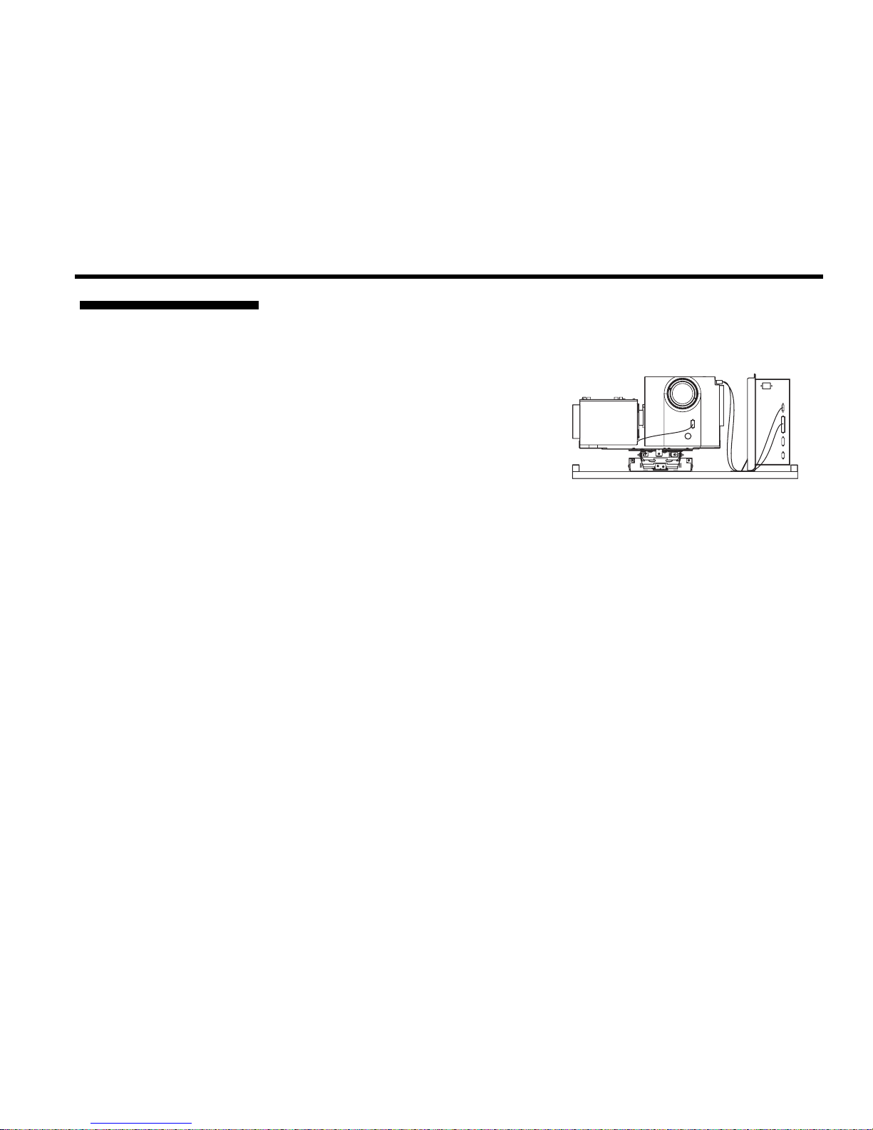
The RPMS-D100U/UF (Rear Pr o ject ion
Module) is a dual lamp projector that has
been specifically designed for rear screen
projection applications. This purposebuilt projector is designed with a flexible
mounting base so that it can be fitted
with various mounting systems. It can
also be configured for 0 degree or 90
degree projection. This flexibility makes the RPMS suitable for nearly any
application. Another feature of the RPMS is the built in 6-axis adjustment
mechanism, which allows for precise geometric alignment with the screen – an
important detail for rear screen tiling applications.
The CS50-D100U & CS70-D100U/UF display cubes are designed to suit many
different applications and are an ideal choice for rea r pro ject ion tiled dis play walls in
control rooms and 24/7 monitoring applications. They provide uniform brightness
and ultimate color matching between screens to create impressive clear, sharp,
seamless images.
Key features (Refer to Section 5 for a complete list of Specifications)
◊ SXGA (1280 x 1024) native resolution with other resolutions fully scaleable in
D100U models only.
◊ Variable Brightness (dependant on lamp power and white boost setting)
◊ User selectable dual lamp or single lamp operation modes
◊ Automatic lamp switching for continuous operation
◊ Intuitive user menu system
◊ Input selection with keypad
◊ Built-in RS-232 and RS-422 ports for computer and network projectors
◊ 6-Axis adjustment mechanism to fine tune image geometry
◊ Low distortion lens (0.76:1 or 1.25:1)
◊ Lens horizontal or lens vertical configurations (CS50/CS70, lens vertical)
◊ 50” – 120” diagonal image size (5:4 aspect ratio)
◊ 24-bit RGB display
◊ Control with IR or wired keypad
◊ Built in RS-232 for control via external computer, etc.
◊ Modular, industrial design for ease of servicing and installation
Figure1.1 RPMS-D100U
RPMS, CS50 & CS70-D100U/UF User’s Manual 1-1

INTRODUCTION
Dealer:
Dealer Phone Number:
Projector Serial Number:
Purchase Date:
Installation Date, if applicable:
The projector accepts an SXGA input signal from an external source. When in Dual
How the projector works
in Single or Dual Lamp
Modes
'
Lamp operation mode, the output from both lamps is directed to a 90° prism. Due to
the placement of the prism, in relation to the lamps, only half of the lamps output is
reflected and the light that doesn’t fa ll inc iden t on the prism is passed on to the
parabolic reflectors inside each of the lamp modules. After one pass around the
system, the light joins the rest of the light that has been reflected off of the prism and
into the focusing lenses. The combined light is then passed through the integrator and
presented to a spinning color wheel where it is sequentially filtered into its RGB
color primaries and presented to the single DMD (in sequence). Reflected light
from the DMD chip then passes through the projection lens and is displayed on a
screen for viewing.
In Single Lamp operation mode, light is passed through the system in the same
manner, but only one lamp is on and light output is reduced by half.
NOTE: The RPMS and CS70 include a four-segment color wheel (red, green, blue
and white). The CS50 includes a six-segment color wheel without a white segment
(red, green, blue, red, green, blue).
Each projection system is provided with a User’s Kit, which includes items required
1.2 Components
in the setup and maintenance of the projector. Check the User’s Kit to ensure you
have received the following items:
♦ User’s Manual
♦ Installation Guide
♦ IR remote keypad with batteries
♦ Assorted ball nose drivers
NOTE: Additional User’s Kits can be purchased separately. Reference CHRISTIE
#38-804867-01 for RPMS-D100U/UF and #38-804827-01 for CS50-D100U, CS70D100U/UF when ordering.
Whether the projector is under warranty or the warranty has expired, Christie’s
1.3 Purchase
Record and
Servicing
highly trained and extensive factory and dealer service network is always available to
quickly diagnose and correct projector malfunctions. Service manuals and updates
are available to service technicians for all projectors.
If you encounter any problems with the projector and require assistance, contact your
dealer or Christie Digital Systems. Fill out the information in the table below and
keep with your records for future refer ence.
NOTE: The projector serial number can be found below the adjustment mechanism on the mounting pla te.
You can also register your product on-line by visiting www.christiedigital.com ⇒
Service and Support ⇒ Product Registration. This will keep you in touch with all
the latest product information, such as updates, technical bulletins, downloads and
Christie newsletters.
1-2
RPMS, CS50 & CS70-D100U/UF User’s Manual
Purchase Record

Section 2
Source Setup
2.1. Introduction
2.2. Source
Connections
This section provides instructions on how to connect various sources to the projector.
A variety of external sources can be connected to the input ports on the Electronics
Module (EM) main input panel. Figure 2.1. illustrates the differences between EM
models D100U (left) and D100UF (fixed frequency shown on right).
NOTE: The EM is vertically mounted to the projector’s mounting rails (orientation
illustrated in Figure 2.1.). For the purpose of illustrating source connections, it will
be shown in a horizontal position.
Figure 2.1. Comparing connector availability between model models
RPMS, CS50 & CS70-D100U/UF User’s Manual 2-1

SOURCE SETUP
V
RGBH
(5 BNCs) '
Input 1 provides 5 BNC connectors for connecting to a variety of sources such as
VGA, SVGA, XGA, SXGA, Mac, PowerMac, DEC, Sun, SGI and others. This
projector supports multiple sync types with RGB signals: sync-on-green, composite
sync, and separate H & V syncs.
To properly connect RGB sources to
INPUT 1 use the table and illustration below
(Figure 2.2.). NOTE: Front panel shown for the D100U model – connection is the
same for D100UF.
RGB Source Outputs
sync-on-green
composite sync
separate horizontal and
vertical sync
Red Green Blue Hor/Comp Vert
√
√
√
Connectors at INPUT 1 (5 BNCs)
√
√
√
√
√
√
√
√
√
NOTE: Connect the Sync BNC inputs first.
Component Video (YPbPr) '
Figure 2.2. Connecting RGBHV sources
Connect a YPbPr signal (component vid eo) to INPUT 1. See Figure 2.3.
NOTES: 1) Not applicable to D100UF models. 2) If, for some reason, the projector
fails to recognize a YPbPr signal, specify this Color Space option within the Image
Settings menu. 2) Do not connect digital component signals to
appropriate digital interface installed at
INPUT 2.
INPUT 1. Use the
2-2
RPMS, CS50 & CS70-D100U/UF User’s Manual

SOURCE SETUP
Figure 2.3. Connecting Component Video Sources
DVI Digital Video Signals '
The DVI Input module installed in INPUT 2 displays digital video input signals
conforming to the DVI (Digital Visual Interface) standard. This is a standard module
in D100U projector models only.
DVI Connection for D100U models
To connect an incoming digital video signal to the projector, connect the cable
running from the source to the DVI input connector at Input 2 - the DVI output
adjacent to the DVI input connector remains em pty . If you want to loop the source
through to another display device, connect a cable from the DVI output connector
(that was empty) to a DVI input connector on the digital display.
Figure 2.4. Connecting a Digital Video Input Signal
RPMS, CS50 & CS70-D100U/UF User’s Manual 2-3

SOURCE SETUP
p
NOTE: The DVI output connector (J94) on the output panel is used to connect the
Projection Head Module (PHM) and Electronics Module (EM).
DVI Loop Through for D100U models
To loop a single incoming digital video input signal (connected to the DVI input)
through to another projector connect a cable from the source to the DVI input
connector on the main input panel. Take another cable and connect it to the DVI
output connector (adjacent to DVI input) and connect it to the DVI input connector of
the next projector. Continue looping connection to all projectors – your last projector
will have an empty DVI output connector.
NOTES: 1) When looping a DVI input signal, all projectors will display the same
data from that one source.
Figure 2.5. Loop Digital Video Input Signals
Com
osite Video '
DVI Connection for D100UF models
The DVI input connector available in D100UF models accepts DVI standard input
signals in the projector’s native resolution only. No loop-through or resizing ability
available on these projectors.
Typical connection to this port is shown in Figure 2.6.
Figure 2.6. Connecting a Digital Video Input Signal to RPMS-500Xef
Connect a composite video input to either the BNC connector or the RCA jack
provided on the video decoder module (
INPUT 3).
NOTE: 1) Requires Optional Video Decoder (38-804600-01). 2) If you want to loop a
composite signal through to another projector or display device, see Video Loop
Through later in this section. 2) Not applicable to D100UF.
2-4
RPMS, CS50 & CS70-D100U/UF User’s Manual
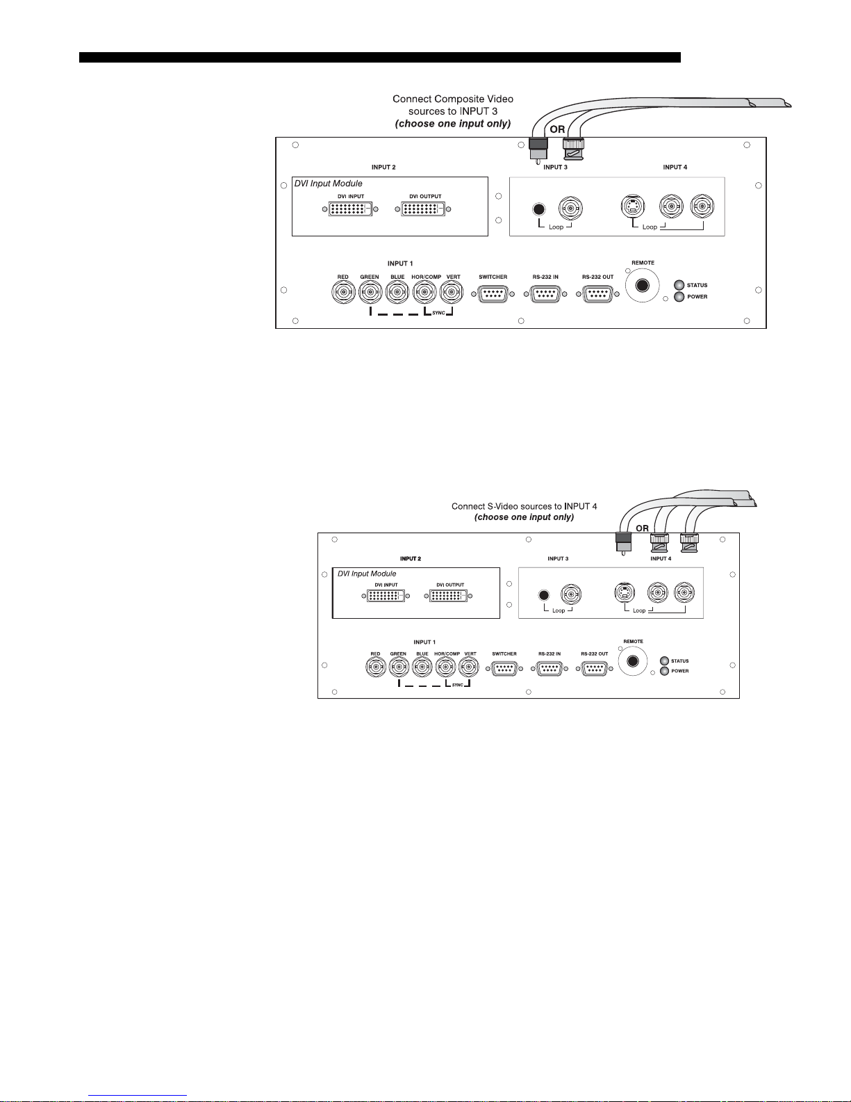
'
S-Video
Connect an S-Video input to either the 4-pin mini DIN connector or the Y and C
BNC connectors provided on the video decoder module (
NOTE: 1) Requires Optional Video Decoder module (38-804600-01). 2) Not
applicable to D100UF.
SOURCE SETUP
Figure 2.7. Connecting Composite Video Sources
INPUT 4).
Video Loop Through '
To loop a single incoming video input signal (connected at the video decoder)
through to another projector or display device, use the empty connector(s) adjacent to
this same input as described below.
Composite Video Loop Through
CONNECTIONS: From your source, connect a composite video signal to INPUT 3 using
either the small RCA plug or the adjacent BNC. Connect a second cable from
whichever
display device or projector. Continue this looping method for each projector, using
either the phono-plug or the adjacent BNC as input into
connector as an output (i.e., loop through). Whether you use the BNC or the phono
plug as input or output depends on the type of cable you have on hand and what type
of connectors are on each end.
Figure 2.8. Connecting S-Video Sources
INPUT 3 connector is free to one of the composite video inputs of the next
INPUT 3, then using the other
RPMS, CS50 & CS70-D100U/UF User’s Manual 2-5

SOURCE SETUP
Figure 2.9. Composite Video Loop Through
VIDEO TERMINATION: In the Video Options menu (Image Settings), make sure Video
Termination is checked for the final projector only. All other projectors must have
this option unchecked in order for the signal to continue. For other types of display
devices in the chain, typically a “Hi-Z” switch position is needed.
S-Video Loop Through
CONNECTIONS: From your source, connect an S-video source signal to INPUT 4 using
either the 4-pin mini DIN or the 2 adjacent BNCs labeled Y and C. Connect a second
cable from whichever
INPUT 4 connector is free to one of the S-video inputs of the
next display device or projector. Continue this looping method for each projector,
using either 4-pin mini DIN or the 2 adjacent BNCs as input into
INPUT 4, then using
the other connector(s) as an output (i.e., loop through). Whether you use 4-pin mini
DIN or the 2 adjacent BNCs as input or output depends on the type of cable you have
on hand and what type of connectors are on each end.
VIDEO TERMINATION: In the Video Options menu (Image Settings), make sure Video
Termination is checked for only the final projector. All other projectors must have
this option unchecked in order for the signal to continue. For other types of display
devices in the chain, typically a “Hi-Z” switch position is needed.
2-6
RPMS, CS50 & CS70-D100U/UF User’s Manual
Figure 2.10. S-Video Loop Through

If you want to use an extra video source in addition to the video source(s) connected at
p
Extra Video
– COMPOSITE OR S-VIDEO
'
INPUT 3 or INPUT 4 connect either a Composite or S-Video source to INPUT 1as shown in.
Do not connect both types here simultaneously. NOTE: For additional video inputs remove
the DVI Input module and install an optional Composite/S-Video Input Module at
SOURCE SETUP
INPUT 2.
Figure 2.11. Connecting Extra Video
O
tional Inputs '
Connecting a switcher '
Christie offers optional modules that allow you accommodate different signal types,
whether analog or digital. Any one of these modules can be installed in D100U
models, in the area labeled
INPUT 2. They include:
• RGB 500 Input Module (38-804606-xx)
• RGB 400 Active Loop Thru Input Module (38-804607-xx)
• RGB 400 Buffered Amplifier Input Module (38-804610-xx)
• Composite/S-Video Input Module (38-804608-xx)
• PC250 Analog Input Module (38-804609-xx)
• Serial Digital Input Module (38-804602-xx)
• Digital HDTV Input Module (38-804611-xx)
• Video Decoder Module (38-804600-01)
NOTES: 1) Connect analog HDTV signals directly to
module installed at
INPUT 2—the optional HDTV Input Module used in earlier
INPUT 1 or to any “RGB” input
Christie projector models is not needed or recommended. 2) See Appendix E,
Optional Input Modules for a brief description of each interface.
You can use one or more external Marquee
Signal Switchers or a third party
switcher in order to significantly increase the number of sources you can select. If
you are using a Marquee
INPUT 1 and connect an RS-232 serial communication cable between the switcher and
the projector serial port labeled
Signal Switcher, connect the switcher’s RGB output to
SWITCHER (see Figure 2.12). The switcher
communication link (permanently set at 9600 baud) enables you to access inputs
connected to the switcher in the same manner as those connected directly to the
projector. For most other third-party switchers, connect and access sources according
to the documentation provided with that switcher. Use high quality shielded cables.
NOTE: Make sure any Marquee
projector is set as “Switcher #1”. If it is not, unplug the switcher and turn the
thumbwheel to “1” before plugging back in and connecting to the projector and/or
network.
Signal Switcher connected directly to the
RPMS, CS50 & CS70-D100U/UF User’s Manual 2-7

SOURCE SETUP
Figure 2.12. Connecting a Marquee Signal Switcher
Connecting Multiple
Switchers
'
If you are using more than one Marquee Signal Switcher, daisy-chain the RS-232
switcher inputs/outputs together to form a complete network of inputs accessible
from the projector (you can network up to 9 switchers), and connect Switcher #1 to
the projector as shown in Figure 2.12. In addition, connect the RGB output from each
switcher to its matching slot on switcher #1–for example, connect the RGB output
from switcher #2 to slot #2 on switcher #1, and the RGB output from switcher #3 to
slot #3 on switcher #1. Note that slots used in this manner on switcher #1 are no
longer recognized as inputs to the projector–if you select a slot location that is
connected to another switcher’s RGB output, the projector will display the “no input
signal” error message.
Multiple projectors can be connected via the serial port inputs on the input panel for
2.3 Serial Port
control using serial communication commands, otherwise known as RS-232.
Connections
Connection: Located just below the video decoder module are two 9-Pin DIN
connectors dedicated to serial communication. Using the appropriate serial
communication cables (see Appendix D) connect the controlling source (PC) to the
RS-232 IN connector.
NOTE: A third RS-232 serial port, located on the main input panel of the EM, is
intended for future use only.
2-8
RPMS, CS50 & CS70-D100U/UF User’s Manual

SOURCE SETUP
Figure 2.13. Connecting to the RS-232 input connector
When connecting multiple projectors in a network with serial communication,
connect the controlling source to the RS-232 IN connector of the first projector in the
network. Then take another serial communication cable and connect one end to the
RS-232 OUT connector and the other end to the RS-232 IN connector of the next
projector. Continue this pattern of connection with all project ors . The last pro ject or in
the network will only have a connection to the RS-232 IN.
Figure 2.14. Looping RS-232 cables between multiple projectors
RPMS, CS50 & CS70-D100U/UF User’s Manual 2-9

SOURCE SETUP
2.4 Power
Connection
Figure 2.15. Connecting RS-232 between multiple projectors
Plug the projector’s line cord into the AC receptacle accessible from the rear of the
projector in the bottom left corner of the Dual Lamp Module (DLM). Then plug the
3-pronged end of the line cord into a grounded AC outlet. Input voltage to D100U
and D100UF models must be capable of 100-240 VAC. Use the proper power
source and the rated line cord provided (North America only). See Section 5,
Specifications for all power requirements.
2.5 Keypad
Protocol
WARNING
Do not attempt operation if the AC supply and cord are
not within the specified voltage and power range.
Caution: Once the projector is powered down, wait approximately 10 minutes to
allow the lamps to cool sufficiently befo re unplugging the projector from the AC
outlet.
At manufacture every keypad is assigned “A” as its default protocol, which is simply
a collection of settings that determine how the keypad operates. Once assigned, this
protocol remains in effect until it is changed—that is, the keypad will operate as it
currently does until you change its protocol.
Protocols are most useful for multiple-projector applications. For example, you might
want to change a keypad protocol if you are working with two projectors and two
remote keypads in the same room and need to control each projector independently
(Figure 2.16). When Keypad A has a different protocol than Keypad B, each keypad
communicates only with the projector having a matching protocol. Or, if you have a
network of two or more projectors connected together via RS-232 serial ports, you
may want only certain projectors to respond to a wired keypad, thus you can use
different protocols to limit r espons es.
NOTE: Matching the protocol on the projector to that of a keypad is done through a
setting in the Communications menu. See menu descriptions for further information
on how to change the projector's infrared sensor (rear and front) protocol.
A protocol for either type of remote keypad — IR or wired — can be changed. A
remote can be changed, manually by "hard-wiring" new jumper settings inside the
keypad so that they remain in effect until you change the hard wiring. Note that a
hard-wired protocol can be temporarily overridden by the software protocol change,
2-10
RPMS, CS50 & CS70-D100U/UF User’s Manual

SOURCE SETUP
effective until the keypad is unplugged and plugged in again (if a wired remote) or
until a battery is removed (if an IR remote).
Figure 2.16. Independent Keypads and Projectors
Remote Keypad
Protocol
IR or optional Wired Keypad
The standard IR remote keypad or the optional wired remote can be set to one of two
'
different protocols — “A” or “B”. To hard-wire a protocol to “A” or “B” in either
remote, follow Steps 1 through 5:
Step 1
Unplug the keypad from the projector (applies to wired remote only).
Step 2
Unlatch and open the empty battery compartment on the back of the keypad as shown
in Figure 2.17.
NOTE: A wired keypad opens as shown, but a cable passes through the battery
compartment cover.
Figure 2.17. Opening the Keypad
Step 3
Find the 4 jumpers located along the latching side of the battery compartment. These
jumpers set the keypad protocol and other settings so that the keypad functions in a
certain manner.
RPMS, CS50 & CS70-D100U/UF User’s Manual 2-11

SOURCE SETUP
Step 4: Set the Jumpers
Set the jumpers as shown in Figure 2.18. Refer to the correct part of the drawing —
IR or wired (optional). Use tweezers or needle-nose pliers to remove and replace
each jumper as necessary.
• J1 jumper: For either remote, set between pins 1 and 2 to set as Protocol “A”.
Set between pins 2 and 3 to set as Protocol “B”.
• J2 jumper: For either remote, set between pins 2 and 3 as shown; otherwise, the
projector will not respond correctly to keypad commands.
• J3 jumper: For the IR remote, make sure that the jumper is set between pins 2
and 3 as shown. For the wired remote, make sure that the jumper is set between
pins 1 and 2 as shown.
• J4 jumper: For the IR remote, make sure that the jumper is set between pins 1
and 2 as shown. For the wired remote, make sure that the jumper is set between
pins 2 and 3 as shown.
Step 5
Replace battery compartment cover. Plug into projector (wired keypad only) and test.
NOTE: A wired keypad can be converted into an IR remote keypad, and vice versa.
Follow the settings shown above, adding or deleting the cable and batteries as
required. The cable is available separately from your dealer – #38-804011-01)
2-12
RPMS, CS50 & CS70-D100U/UF User’s Manual
Figure 2.18. Locating and setting keypad jumpers

Convertin
g
a Keypad '
SOURCE SETUP
If desired, you can convert an IR remote keypad into a wired remote keypad and vice
versa.
TO CHANGE FROM INFRARED TO WIRED:
1. Remove battery compartment cover from back of keypad.
2. Remove batteries.
3. Wait 1-2 minutes.
4. Set keypad protocol as desired, using “wired” jumper settings.
5. Plug the keypad cable (available separately) into the empty battery
compartment. Make sure that the battery cover is notched smoothly to
accommodate the cable.
6. Replace battery compartment cover.
7. Plug into the 3-pin XLR port at the rear panel of the projector.
TO CHANGE FROM WIRED TO INFRARED:
1. Unplug the keypad from the projector.
2. Open the keypad cover and unplug the keypad cable.
3. Wait 1-2 minutes.
4. Set keypad protocol as desired, using “IR” jumper settings.
5. Install batteries (see Section 4).
6. Replace battery compartment cover.
RPMS, CS50 & CS70-D100U/UF User’s Manual 2-13


Section 3
Operation
3.1 Introduction
3.2 Projector
Basics
This section provides a general overview of the projector and a complete description
of the menu system.
The projector’s modular architecture is best suited for control room and mission
critical environments where ease of servicing is a must and down time must be kept
to a minimum. A brief description of each module has been provided in this section.
Knowing your projector will help you in times where troubleshooting is necessary.
Figure 3.1. Identifying Projector Modules
Projector Head Module (PHM)
The PHM module is the centermost module of the projector. It contains the
projection lens (0.76:1 or 1.25:1), IR sensor, color wheel, DMD and other optical
components. It also provides the electrical interfaces required to drive these
components.
The PHM is connected to the adjacent DLM module. As an assembly, the two
modules are mounted to the 6-axis adjustment mechanism. With a quick changeover
in mounting brackets the PHM can be removed, rotated 90°, and re-mounted for rear
screen projection applications where a first surface optical mirror is used.
Dual Lamp Module (DLM)
The DLM connects to the adjacent PHM module, by a specially designed coupling
that allows rotation of the PHM module only This module houses the two 100W
lamps, two lamp drivers, a 390V high voltage power supply (HVPS) and cooling
fans.
90°, like the PHM.
The DLM is designed to remain in a horizontal position and does not get rotated
RPMS, CS50 & CS70-D100U/UF User’s Manual 3-1

OPERATION
Electronics Module (EM)
The EM module contains the main electronics and input connectors of the projector.
Your projector model identifies which type of EM you have D100U or D100UF.
Main Input Panel
All source connections are made to the main input panel. NOTE: The
connectors located on the input panel vary between models. See Section 2.
Auxiliary Fan Connector
A connector exists on the side of the EM and can be used to connect a
separate cooling fan – useful in applications where the projector is mounted
within the confines of an enclosure and where airflow is required.
Refer to Appendix D for pinout information.
Status and Power LEDs
Two LEDs are located in the lower right corner of the main input panel,
which indicates projector “Status” (top) and “Power” (bottom). During
normal operation, the “Power” light is steady green and the “Status” light
flashes green each time a key is pressed on the keypad or the projector
receives a serial communication command.
6-Axis Adjuster
The projector provides the ability of modifying the geometry of a displayed image
using the uniquely designed 6-Axis adjustment mechanism. This mechanism is
shipped from the factory in a nominal position and can be adjusted using a 3/16” ball
driver. All adjustments made to the adjuster can be “locked” into place by tightening
the lock screws and setscrews. Instructions and tools required to adjust the 6-axis can
be found in the User’s Kit.
3-2
RPMS, CS50 & CS70-D100U/UF User’s Manual

3.3 Using the
Keypad
OPERATION
The projector is controlled via an IR remote keypad. The
keypad accesses various menus in which settings can be
changed and saved into memory (called channels). There
are 99 channels in which you can store customized settings
for various sources.
The IR remote keypad provided in the User’s Kit provides
the user with wireless control of the projector of up to 100
feet away. The keypad is operated by 4AA batteries, which
require periodic replacement (Section 4).
The most effective method of operating the projector is by
facing and pointing the keypad directly at the screen.
There is only one IR sensor that picks up the transmissions
of the keypad and it is located just below the lens. It is
important to keep the transmission path clear because any
obstruction will limit if not prohibit transmission of
commands.
IR Remote Keypad '
Wired Remote '
—OPTIONAL—
The IR Remote Keypad controls the projector by way of
wireless communications from a battery-powered infrared
(IR) transmitter. Use the IR remote keypad the same way
you would use a remote keypad supplied with a TV or
VCR. When making key presses, point the keypad directly
at the center of the screen. The IR sensor, responsible for
detecting signal and relaying commands for internal
processing, is located just below the projection lens on the
PHM.
The wired remote keypad connects to the 3-pin XLR jack via a 25 ft. cable. It is
recommended when:
• the lighting conditions are unsuitable for proper IR transmission
• you want to use a separate keypad for each projector in a group
NOTES: 1) For extra long distances and/or harsh environments, you may prefer to
use an optional remote Two-Way Controller to control the projector. For operating
details, please see the Two-Way Controller User’s Manual included with this
accessory.
Keep in mind the following guidelines:
1. Press keys one-at-a-time; there are no simultaneous key presses required.
Power
*
2. For any key having an “*” (
, for example), hold the key for approximately
1 second in order to toggle the function with a single key press. For other keys
(or to use a “*” key in conjunction with
ON
or
OFF
), a momentary press similar
to a mouse click is sufficient.
3. Press the “lightbulb key” to temporarily illuminate the backlight for the keys
without sending any other command.
4.
, ,
ON
, and
OFF
repeat their “arrow” actions when held down. For other
keys, release and press again to repeat an action. In a network, pause between
adjustments to ensure that the last projector can “keep up” with the commands.
RPMS, CS50 & CS70-D100U/UF User’s Manual 3-3

OPERATION
yp
y
5. If you press a key while the projector is busy with another action, such as during
a power-up, the key press may not take effect.
When you turn on the projector it begins operating at presentation level, such as an
image from the most recently used source signal. The projector temporarily leaves
presentation level whenever you use the keypad to work with control settings, display
Menu
menus, or on-line help. For example, pressing
after startup displays the m ain
menu — presentation level is no longer active, although the image still appears in the
background. Press
Menu
again (or
Exit
) to return or leave the menu system and return
to presentation level.
Ke
ad Commands '
Power
*
Chan
Specific keypad commands are explained below:
Power ON/OFF
Press and hold for approximately 1 second to turn the projector ON or OFF with a
single key press. Or press
Power
*
followed immediately by
ON
or
OFF
if you want to
guarantee the correct toggle (useful if you are unsure of the present status).
If you power up in Single Lamp mode with a failed lamp, the projector will
automatically try re-striking it up to 3 times (after the initial attempt) with a 30
second wait in between each attempt. This could lead to a 2-minute wait before the
lamp turns on or is declared, “failed to strike”. If this occurs, the projector continues
powering on by trying to turn on the other lamp. The same happens when you power
up in Dual Lamp mode and one lamp fails to turn on. The projector tries re-striking
the lamp that did not turn on up to 3 times before it reverts to the single lamp mode of
operation for the lamp that is on. In either case, there is no indication by the LEDs
that anything is occurring. Any key that is pressed during this time is ignored, except
for
Power
OFF
*
.
NOTES: 1) It is recommended that you wait at least 10 minutes after powering down
the projector and before unplugging it from the power outlet. Th e cooling fans in t he
projector DO NOT automatically turn off when the lamp is cool. This wait period
gives the lamp enough time to cool before unplugging the projector.
Channel
Chan
Press
to select a specific source setup (channel) defined and stored in projector
memory. Once you enter a 2-digit channel number (or, if there is a list displayed,
Enter
highlight it and press
), the display will automatically change and update
according to the numerous setup parameters defined for that channel.
NOTE:
Display Channel option is selected in the Menu Preferences menu. You can choose
to use a scrollable list of channels when you press
the desired channel number “blind”, i.e., without on-screen feedback. See Menu
Preferences later in this section.
Stb
*
Standby
Press
the projector in a warmed-up and ready state. Or quickly press and release
follow immediately by
(useful if you are unsure of the present status). Note that the lamp and electronics
remain ON in standby mode, even though the image turns to black and most
3-4
RPMS, CS50 & CS70-D100U/UF User’s Manual
Chan
key behavior during a presentation depends on whether or not the
Chan
, or you may prefer to enter
Stby
*
and hold for approximately 1 second to blank the display while keeping
ON
or
OFF
if you want to guarantee the correct toggle
Stby
*
and

OPERATION
t
N
, ,
functions are disabled. To leave standby press and hold
Menu
OFF
). Or simply press
Menu
Menu
Press
Exit
to display the Main menu. A list of several options appears for access to
or
Menu
.
specific functions, such as Configuration or Image Settings. Press
Stby
*
again (or use
Menu
Stby
again to
*
remove all menus and return to presentation level.
Enter
Enter
Enter
Press
to select a highlighted item, to toggle a checkbox (checked vs.
unchecked), or to accept a parameter adjustment and return to the previous menu or
image.
Exi
Exit
Exit
Press
NOTE:
to return to the previous level, such as the previous menu.
Exit
does not save changes within text editing boxes (including number
editing of a slidebars) or within pull-down lists. It acts as a “cancel” in these cases.
O
OFF
,
Arrow Keys
The arrow keys have a variety of functions depending on the situation. Some typical
uses are described below. See also Editing Text later in this section.
• Use
or to change a slidebar value—hold as desired for continuous
adjustment (note the adjustment increments and range depend on the parameter
being adjusted).
• Use
or to change to a different option within a pull-down list without
having to display the list first
• Use
or to jump between “pages”, such as in Help or lengthy pull-down
lists.
Use the
ON
or
OFF
keys to navigate within a menu, pull-down list or text box, or to
increase or decrease the value in the second (bottom) slidebar of a double slidebar.
You can also use
ON
or
OFF
in conjunction with certain toggle keys—i.e., those
including an asterisk symbol—to ensure a toggle only in the desired direction. If you
Power
*
press
and hold it for approximately 1 second in hopes of turning the projector
on, the projector will actually turn off if the projector was already on. Instead, to
avoid the risk of toggling in the wrong direction, quickly press and release normal l y
Power
*
the function key you wish to toggle (in this case
seconds) press either
ON
or
OFF
as desired. The specific toggle will occur.
). Then immediately (within 2
Toggle keys are labeled with an asterisk on the keypad. They are listed below:
Stby
*
•
•
•
+ ON = put the projector in standby mode
Stby
Power
Power
DisplayDisplay
DisplayDisplay
OFF
*
+
*
*
*
*
= leave standby
ON
+
= turn the projector on
OFF
+
= turn the projector off
+ ON = turn the menu system on
OFF
+
= turn the menu system off
RPMS, CS50 & CS70-D100U/UF User’s Manual 3-5

OPERATION
t
t
n
Con
Contrast
Cont
Press
to change the amount of white in your images. Use and until you
reach the desired level of contrast—for best results, start low and increase so that
whites remain bright but are not distorted or tinted, and that light areas do not
become white (i.e., are “crushed”). Conversely, low contrast causes dim images. See
Image Settings.
Brigh
Brightness
Bright
Press
to increase or decrease the amount of black in the image. Use and
until you reach the desired level of contrast—for best results, start high and
decrease so that dark areas do not become black (i.e., are “crushed”). Conversely,
high brightness changes black to dark gray, causing washed-out images. See Image
Settings.
Proj
Projector
Proj
Press
when you want to access a specific projector within a network or if you
simply need to see if the local projector is listening. The number appearing in the
“Enter Number” window indicates which projector is currently listening to
commands, and will match the projector number that has been defined in its
Communications menu.
The “Projector” checkbox (read-only) shows whether or not the projector physically
connected to a keypad is listening to commands from that keypad. A checkmark
means that connected projector is listening; if there is no checkmark, you are
communicating with a different projector.
Enter the 3-digit number assigned to the specific projector you want to use. Press
Enter
to select, press
Exit
to cancel. If you switch to a projector other than the one you
are currently using, the checkmark will be deleted.
Press
Proj
and then
Proj
again without entering a projector number to broadcast to
multiple projectors. Keypad commands will then affect all projectors present.
NOTES: 1) The "Broadcast Keys" option in the Communications menu must be
selected for only one (any) projector in a serial network. The keypad in use must be
OFF (disabled) for the remaining projectors. See Keypad Protocols and
Communications later in this section.
Pixel
Pixel
Pixel
Press
tracking first: use
to access the pixel tracking and pixel phase double slidebar. Adjust pixel
or to increase or decrease the frequency of the pixel
sampling clock to correct consistency of the image. For proper phase, use
OFF
to increase or decrease pixel phase so that any shimmer disappears and the
image is stable throughout. See Size and Position for a com plete expl ana tion of
tracking and phase.
ON
and
Positio
Position
Press
3-6
RPMS, CS50 & CS70-D100U/UF User’s Manual
Position
to move the image using the double slidebar. At the slidebar, use or
to move the image left or right, use
ON
or
OFF
to move the image up or down.

Func
t
Function Key
From presentation level, press
color or colors in the display. For example,
6 7
Func
data,
will display all colors data. The list of available color combinations is
Func
followed by a 2-digit number to enable a specific
Func
6 4
will display only red and green
shown below and also appears on the back of the IR remote keypad. Color enabling
can also be accessed through the menu system rather than these shortcuts.
6 1
NOTE: Once
Func
Func
Func
Func
Func
Func
Func
Func
is pressed in presentation level, the projector will not respond to
= Red
6 2
= Green
6 3
= Blue
6 4
= Red and Green
6 5
= Green and Blue
6 6
= Red and Blue
6 7
= All colors (
Exit
does the same thing)
non-numeric entry until 2 digits have been entered or until 5 seconds of inactivity
have elapsed.
Func
Use of the
elsewhere in Section 3. For example, press
key within the menu system is noted with the appropriate topic
Func
in the Channel Setup menu to enable
deletion or copying of a channel.
OPERATION
OSD
*
OSD* (On-screen display)
OSD
*
Press and hold
visible or invisible). Or press
for approximately 1 second to toggle menus on or off (i.e.,
OSD
*
followed immediately by ON or
OFF
the correct toggle direction (useful if you are unsure of the present status). Note that
invisible menus are fully functional.
NOTES: 1) With OSD on, you can still mute menus, error messages, slidebars, etc.
with the appropriate setting in the Preferences menu.
Help
Help
Help
Press
again to exit. From presentation level, press
for detailed information about any current menu and highlight. Press
Help
to access the General Help menu
consisting of Using Help, Setup, Keys, Source (Input) Selection, and Stat/Pwr LEDs.
Exit
Press
Te s
Test
Press
next available pattern in the sequence.
Exit
to leave General Help and return to presentation level.
Te st
to display one of the available test patterns. Press
Te st
will exit after the last pattern, or press
Te st
again to display the
at any time to remove the current test pattern from the screen and return to
presentation level.
NOTE: For a complete list of all test patterns, see the Geometry menu description
later in Section 3.
to guarantee
Help
DisplayDisplay
*
Display *
Use
second to toggle on or off with a single key press. Or quickly press and release
DisplayDisplay
*
to hide the current menu. Press and hold
RPMS, CS50 & CS70-D100U/UF User’s Manual 3-7
DisplayDisplay
*
for approximately 1
OPERATION
3.4 Navigating the
Menus
DisplayDisplay
*
and follow immediately with ON or
OFF
if you want to guarantee the correct
toggle (useful if you are unsure of the present status).
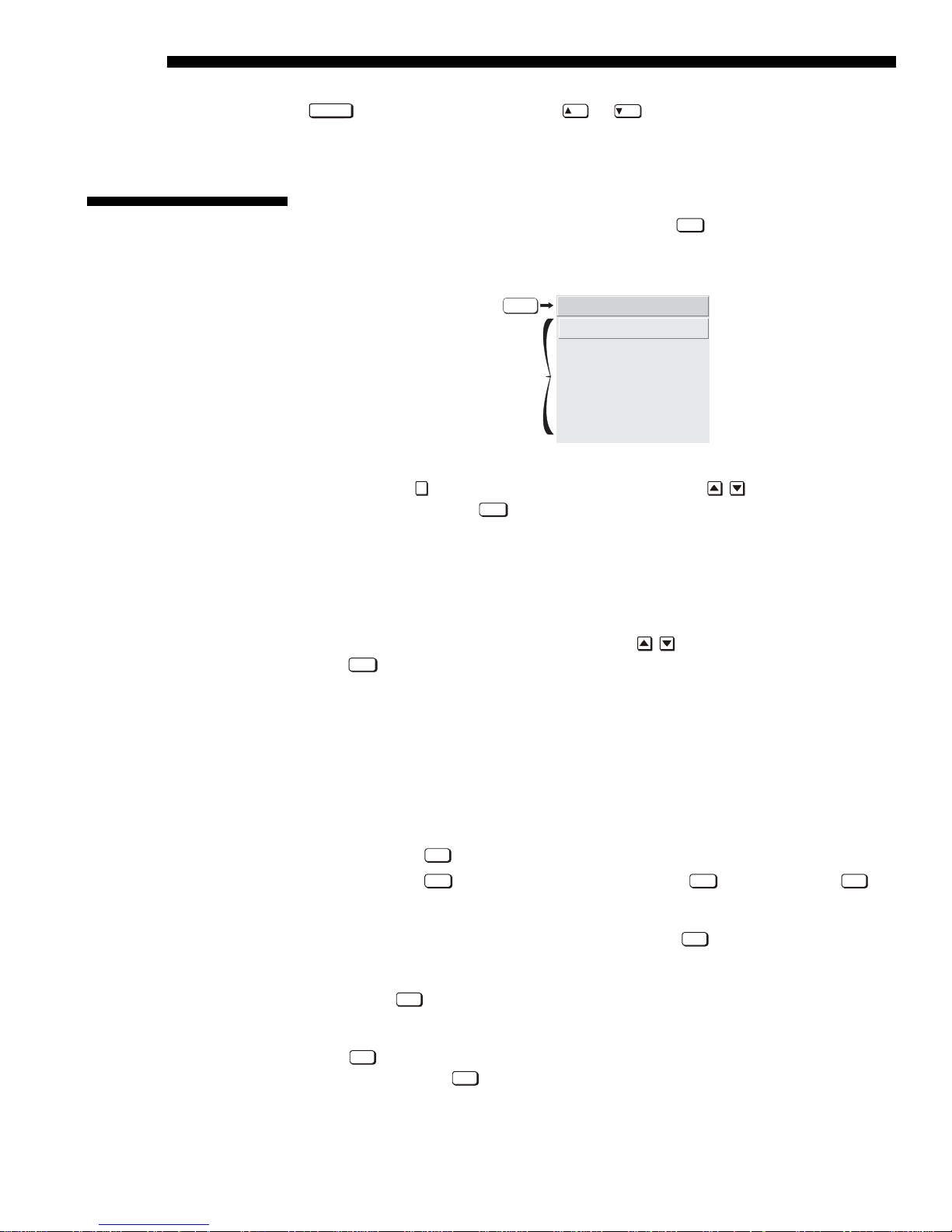
Most of the controls for the projector are access ed fro m within the projector’s menu
Menu
system. The Main Menu is accessible by pressing the
key on the remote keypad.
This menu is accessible at any time during operation. From it you can access various
other “sub-menus” with related functions.
menu
Choose a
function
Main Menu
1.
Size and Position
2.
Image Settings
3.
Channel Setup
4.
Configuration
5.
Lamp
6.
Status
7.
Auto Setup
On the keypad, either enter the number corresponding to the sub-menu you wish to
2
access, such as
desired option and press
for the Image Settings menu, or use the
Enter
. The sub-menu you selected will then appear.
keys to highlight the
The only menu item that does not offer a sub-menu, but activates an action is “AutoSetup”. When selected it will begin an automated process of optimizing critical
display parameters such as size, posit ion, pix el tra ck in g , etc.
On-line Help '
Once you have a sub-menu displayed, navigate in a similar manner—enter a menu
option number for any numbered option, or use
Enter
press
at the desired option. Extra long menus have a scroll bar on the right–use
to move the highlight and
the arrow keys to see the remainder of the menu. Items that are locked out or do not
pertain to the current action appear “grayed-out” and cannot be selected.
NOTES: 1) If there is no signal present, all source-dependent adjustments are
disabled. 2) After 15 minutes of inactivity, the projector leaves the menu system and
returns to the presentation. 3) The Status menu is read-only.
When finished with a sub-menu, do one of the following:
Exit
• Press
• Press
to return to the previous screen
Menu
to return to the main menu, press
Menu
a second time or
Exit
to
return to presentation level
Help
If at any time you are uncertain what to do next, press
to display detailed
information about the current menu or highlighted option. A scroll bar appears on the
right-hand side of a help window if there is additional text–use the arrow keys to
scroll. Press
Help
again to exit. At the bottom of some menus, a line of hint text also
appears.
Help
Press
within a topic. Press
, from presentation level to access general Help Topics. Scroll as necessary
Exit
to return to your presentation.
3-8
RPMS, CS50 & CS70-D100U/UF User’s Manual

Figure 3.2. General Help Topics
OPERATION
Time-outs '
Whenever the projector is not at presentation level, such as when there is a slidebar,
menu, message or test pattern displayed, you have limited time in which to make a
keypad entry before the projector returns to presentation level and the graphic
disappears. These time-outs vary depending on the current display, as shown in the
following chart:
The Global Icon '
A menu item marked with a global icon means that any changes made to that option
are global to the projector and will be applied to all incoming signals.
Using Slidebars and
Other Controls
Most of the sub-menus allow you to change settings by using slidebars, checkboxes,
'
and pull-down lists. To select a slidebar, toggle a checkbox status, or view a pulldown list, do one of the following:
• Enter the menu option number corresponding to the setting you wish to change
Or press
• move the highlight to the desired parameter and press
• move the highlight to the option desired and press or .
• Or bypass menus entirely and use a single key to immediately access an
Once selected, change the setting as desired (see below) and press
return to the current sub-menu.
TIME-OUTS
Slidebar (from pres.) 5 seconds
Slidebar (from menu) 15 minutes
Lamp Timer Msg. 30 seconds
Channel entry 5 seconds
Other 15 minutes
to:
2
for Size in the Size & Position menu).
Enter
.
(for example, press
ON
or
OFF
adjustment (Note: This applies only to options having their own key, such as
Position, Pixel, Bright, and Contrast).
Enter
to save and
SLIDEBARS IN MENUS - The current value for a given
option, such as size or vertical stretch, appears to the left
of its slidebar icon. This number may express a percentage or specific units (such as
pixels, degrees Kelvin, etc.), depending on the option. Press
adjust the setting up or down—both the number and the length of the bar change
accordingly (for continuous adjustment, hold down the desired arrow key). Or press
press
or to gradually
Enter
to activate a slidebar text box for specific number entry via the keypad, then
Enter
or and
to save (or press
RPMS, CS50 & CS70-D100U/UF User’s Manual 3-9
Exit
to cancel).

OPERATION
DOUBLE SLIDEBARS - In double slidebars, such
as the Pixel Tracking / Pixel Phase double
slidebar, adjust the top slidebar with
or
as desired. When you have finished with
the top slidebar (whether changed or not),
adjust the bottom slidebar with
When you are done, press
Exit
ON
to return to your presentation. For fast continuous
or
OFF
.
adjustments, hold down the desired arrow key.
DIRECT SLIDEBARS - For quick access, you can often use a slidebar (or double
slidebar) without traveling the menu system. For example, simply press
immediately display the same contrast slidebar accessed with the “Contrast”
Cont
to
option
in the Image Settings menu. Direct slidebars are listed below.
LIST OF DIRECT SLIDEBARS
H-Position or V-Position
Pixel Tracking or Phase
Contrast
Brightness
Position
Pixel
Cont
Bright
Enter
Use the arrow keys to adjust a direct slidebar, or press
number from the keypad, then
Exit
you are done, press
to save and return to your presentation.
Enter
or or to save ( or
and enter a specific
Exit
to cancel). When
NOTES: 1) You can still adjust a direct slidebar as usual if the menu display is
OSD
*
turned off (see
or Menu Preferences menu) — the slidebar just won’t be visible.
2) A direct slidebar disappears if it is not used within 5 seconds.
CHECKBOXES - Conditions are present if its adjacent
checkbox contains a checkmark. To toggle the checkbox,
Enter
simply highlight and press
, or highlight and use to check and to
uncheck. For a checkbox that is numbered, simply enter the number of the option to
toggle the checkbox.
PULL-DOWN LISTS – To see a pull-down list of options availab le for a giv en
parameter labeled with a
Use
noted with a small
3-10
RPMS, CS50 & CS70-D100U/UF User’s Manual
▼, you can:
• Highlight it and press
Enter
• Or enter the menu option number.
ON
or
OFF
keys to navigate up and down within the list (the current choice is
'). Press
Enter
to choose an option from the list, if desired.

Figure 3.3. Example of Pull-Down List
g
OPERATION
Editin
Text '
Or, if you prefer to quickly scroll through a list without first pulling it down,
highlight the option and use
NOTES: 1) Press
list. 2) Press
ACTIVATE THE EDIT WINDOW: To enter or edit text, highlight the desired parameter
Exit
or to jump between “pages” in an extra long pull-down
while in a pull-down list to cancel any change.
(such as a Channel Name) and press
or . Press
Enter
Enter
when the desired choice appears.
to activate its adjacent edit window. Any
previously entered text is displayed with its first character highlighted in a square
cursor, signifying that this character is ready for editing.
Figure 3.4. Entering Text
NAVIGATE WITHIN THE EDIT WINDOW: Press to move the cursor forward or
to move the cursor backwards as desired.
EDIT A CHARACTER: To edit a highlighted character, use
the alphabet, numbers, spaces and punctuation available. When the character you
need appears, press
current text, if present. Note that you can also enter a number directly from the
keypad—it will be accepted and the cursor will move on.
ADD OR DELETE A CHARACTER OR SPACE: To insert a space at the cursor location,
press
Func
to select it—the cursor will move to the next character of
. To delete a highlighted character (or space), press
RPMS, CS50 & CS70-D100U/UF User’s Manual 3-11
and
to scroll through
Func
.

OPERATION
g
Editin
Numerical Values '
3.5 Using Inputs
and Channels
Enter
WHEN FINISHED: To accept the edits and move out of the edit window,
Enter
.
Exit
at any time to cancel changes and return to the previously defined
PRESS
press
NOTE: Press
text.
Enter numbers directly from the keypad in order to specify numbers representing
projectors, channels (source setups), switchers, or slots. As each digit is entered, it is
displayed and the cursor moves on. Note that channel numbers are defined with 2
digits—for example, if you enter only a single digit (like “7”) for a channel number,
the channel will automatically be defined as “07”. Use “07” to utilize this channel.
NOTES: 1) Once you enter the first digit, this digit replaces all old digits. 2) If you
press any non-numbered key, the number entered up to that point is accepted and
Exit
updated as the new value. 3) Press
to cancel editing of numerical values.
NOTE: See Section 2, Source Setup, for a full explanation of how to connect a
variety of sources to the projector.
The projector stores and automatically recalls up to 99 different channels (source
setups) for a variety of inputs. This memory feature allows you to define and
conveniently use a wide variety of customized setups rather than having to repeatedly
re-configure the projector for different presentations. Each physical source (i.e.,
input) can have several different channels associated with it.
Do I Select an Input '
Or a Channel?
3-12
RPMS, CS50 & CS70-D100U/UF User’s Manual
INPUT – An input simply describes a physical location for an incoming signal
connection. These connections are always either on the projector itself (one of the
four inputs at the rear of the projector) or on any switcher connected to the
Input
projector’s switcher port.
describes the source signal according to two specific
criteria only—to which switcher it is connected and to which slot it is connected—
and is identified by a 2-digit number entered on the keypad. The first digit specifies
the switcher (0-9), the second specifies the slot (1-9). Note that the projector is
always considered “switcher #0”.
EXAMPLES:
Input
13
0
Input
33333
3
= use source connected to switcher #1, slot #3
1
= use source connected to the projector, slot #1
To switch between input ports (if your projector has a switcher connected to it) press
Input
the
key and enter the 2-digit number representing the switcher and slot location
for the desired signal. (Note there is no on-screen feedback for entering the numbers.)
If it is the first time you have used the source/input (or if you used the input
but did not define a channel by adjusting anything), the projector will recognize the
OPERATION
w
new input signal based on its frequencies and polarities, and will automatically
display an image according to default settings for such a signal.
If you used the source once before and changed a display parameter
such as contrast, V-Position etc., then a channel was automatically created and still
exists in projector memory (see below). Selecting an
0
3333
333
or
Input
0 4
) will automatically recall this channel—and all its setup
Input (Input
0 1
0 2
Input
,
Input
,
parameters—and update the display accordingly. Note: If more than one channel
exists for the input, the image will be displayed according to the setup parameters for
the first channel with matching characteristics.
CHANNEL - A channel is a collection of measurements, locations and settings that
tailor a display to your specific needs. Since source types and applications can vary
greatly, you will likely want to adjust and define a wide variety of parameters, such
as brightness, contrast, size, etc., in order to customize and optimize the display
coming from a particular source. For example, the display settings you choose for a
VCR source may be very different from those you choose for a high resolution
computer source, or one signal may simply vary from another signal used earlier
through the same input location. Once you have adjusted a display parameter, such as
pixel tracking or contrast, all current settings are collectively stored in the projector's
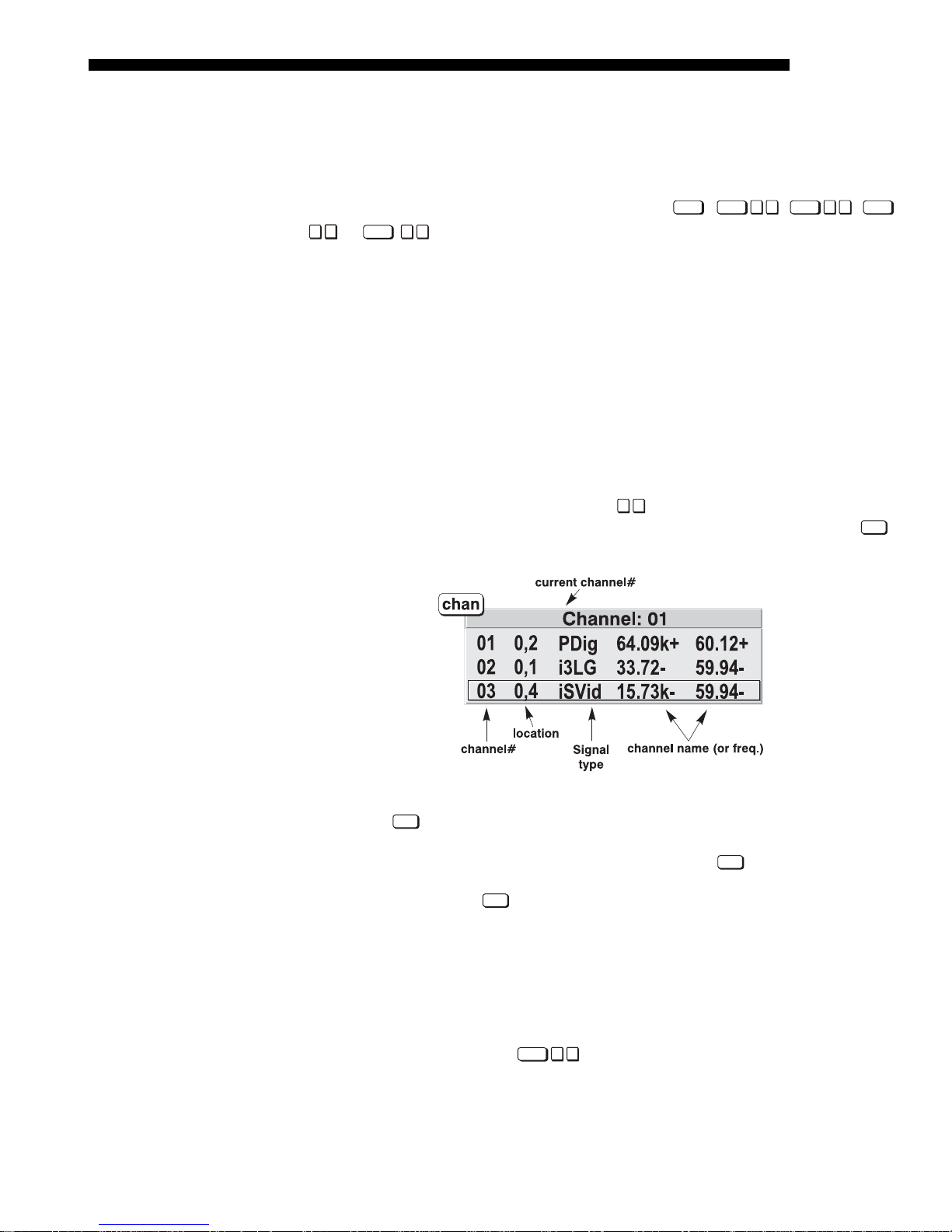
0 9
memory as a unique 2-digit channel, such as
channels available for the same input, any of which can be selected by using the
. You can have numerous distinct
Chan
key on the keypad followed by the 2-digit channel number.
NOTE: The
defined within the Menu Preferences menu (see Menu Preferences later in this
section). Figure 3.5 is a sample channel list available from
In order to use channels (
To use a new source with the projector, a new channel must be added to projector
Creating a Ne
Channel
— AUTOMATIC —
'
memory so that the projector will respond properly to an input signal from that
source in the future. A new channel can be created automatically, as described here,
or it can be copied from an existing channel and then edited as necessary (see
Copying or Deleting Channels later in this sect ion ).
When you select an input (eg.
searched for matching input and signal parameters. If no match to the incoming input
signal is found in the currently defined channels, a new channel is temporarily
created based on factory-defined defaults for this signal. The channel number
assigned to this channel is the lowest available number from 01-99.
Figure 3.5. Channel List
Chan
key may display a channel list or not, depending on what you have
Chan
.
Chan
on the keypad), you must first create them. See below.
0 1
Input
) the existing channels in the projector are
RPMS, CS50 & CS70-D100U/UF User’s Manual 3-13
 Loading...