

Christie Entero RPMWU, Entero RPMSP, Entero RPMHD-LED01, Entero RPMSP-LED01, Entero RPMWU-LED01 User Manual

Entero RPMWU/RPMSP/RPMHD-LED01
USER MANUAL
020-100367-05


Entero RPMWU/RPMSP/RPMHD-LED01
USER MANUAL
020-100367-05

NOTICES
COPYRIGHT AND TRADEMARKS
© 2011-2012 Christie Digital Systems USA, Inc. All rights reserved.
All brand names and product names are trademarks, registered trademarks or trade names of their respective holders.
REGULATORY
The product has been tested and found to comply with the limits for a Class A digital device, pursuant to Part 15 of the FCC Rules.
These limits are designed to provide reasonable protection against harmful interference when the product is operated in a
commercial environment. The product generates, uses, and can radiate radio frequency energy and, if not installed and used in
accordance with the instruction manual, may cause harmful interference to radio communications. Operation of the product in a
residential area is likely to cause harmful interference in which case the user will be required to correct the interference at the
user’s own expense.
This Class A digital apparatus complies with Canadian ICES-003.
Cet appareil numérique de la classe A est conforme à la norme NMB-003 du Canada.
이 기기는 업무용 (A 급 ) 으로 전자파적합등록을 한 기기이오니 판매자 또는 사용자는 이점을 주의하시기 바라며 , 가정 외의 지역에서
사용하는 것을 목적으로 합니다 .
GENERAL
Every effort has been made to ensure accuracy, however in some cases changes in the products or availability could occur which
may not be reflected in this document. Christie reserves the right to make changes to specifications at any time without notice.
Performance specifications are typical, but may vary depending on conditions beyond Christie's control such as maintenance of
the product in proper working conditions. Performance specifications are based on information available at the time of printing.
Christie makes no warranty of any kind with regard to this material, including, but not limited to, implied warranties of fitness for
a particular purpose. Christie will not be liable for errors contained herein or for incidental or consequential damages in
connection with the performance or use of this material.
The product is designed and manufactured with high-quality materials and components that can be recycled and reused. This
symbol means that electrical and electronic equipment, at their end-of-life, should be disposed of separately from regular
waste. Please dispose of the product appropriately and according to local regulations. In the European Union, there are separate
collection systems for used electrical and electronic products. Please help us to conserve the environment we live in!
Canadian manufacturing facility is ISO 9001 and 14001 certified.
GENERAL WARRANTY STATEMENTS
For complete information about Christie’s limited warranty, please contact your Christie dealer. In addition to the other limitations
that may be specified in Christie’s limited warranty, the warranty does not cover:
a. Damage occurring during shipment, in either direction.
b. Projector lamps (See Christie’s separate lamp program policy).
c. Damage caused by use of a projector lamp beyond the recommended lamp life, or use of a lamp supplied by a supplier other
than Christie.
d. Problems caused by combination of the product with non-Christie equipment, such as distribution systems, cameras, video
tape recorders, etc., or use of the product with any non-Christie interface device.
e. Damage caused by misuse, improper power source, accident, fire, flood, lightening, earthquake or other natural disaster.
f. Damage caused by improper installation/alignment, or by product modification, if by other than a Christie authorized repair
service provider.
g. For LCD projectors, the warranty period specified applies only where the LCD projector is in “normal use.” “Normal use”
means the LCD projector is not used more than 8 hours a day, 5 days a week. For any LCD projector where “normal use” is
exceeded, warranty coverage under this warranty terminates after 6000 hours of operation.
h. Failure due to normal wear and tear.
PREVENTATIVE MAINTENANCE
Preventative maintenance is an important part of the continued and proper operation of your product. Please see the
Maintenance section for specific maintenance items as they relate to your product. Failure to perform maintenance as required,
and in accordance with the maintenance schedule specified by Christie, will void the warranty.

Table of Contents
1: Introduction
1.1 Labels and Markings ...................................................................................................................1-1
1.2 Safety Warnings and Guidelines .................................................................................................1-1
1.3 Purchase Record and Service Contacts .......................................................................................1-2
1.4 Projector Overview......................................................................................................................1-2
1.4.1 Projection Head Module (PHM)..........................................................................................1-3
Main Power Switch ..............................................................................................................1-3
1.4.2 Electronics Module (EM) ....................................................................................................1-3
Input Panel ............................................................................................................................ 1-3
Status Display .......................................................................................................................1-3
Status LED ............................................................................................................................ 1-3
IR Sensor ..............................................................................................................................1-3
1.4.3 Key Features ........................................................................................................................ 1-4
1.4.4 How the Projector Works ....................................................................................................1-4
1.4.5 List of Components.............................................................................................................. 1-4
2: Setting Up a Source
2.1 Projector Power ...........................................................................................................................2-1
2.1.1 Turning the Projector ON .................................................................................................... 2-1
2.1.2 Disconnecting the Projector from AC .................................................................................2-1
2.1.3 Re-connecting the projector to AC ......................................................................................2-2
2.2 Connecting Sources .....................................................................................................................2-2
LEDS ....................................................................................................................................2-2
DVI Digital Video ................................................................................................................2-3
Dual Link DVI Input Card ....................................................................................................2-3
Twin HDMI Input Card ........................................................................................................2-3
Analog BNC Input Card .......................................................................................................2-4
Dual SD/HD - SDI Input Card .............................................................................................2-4
Video Decoder Input Card .................................................................................................... 2-4
2.3 How Color Settings Interact in a Entero Array ...........................................................................2-5
2.4 Optimizing the Projectors for the Source ....................................................................................2-6
3: Operation
3.1 Using the IR Remote ...................................................................................................................3-1
3.1.1 IR Remote ............................................................................................................................3-2
3.1.2 Wired Remote ......................................................................................................................3-3
3.1.3 IR Remote Commands.........................................................................................................3-3
Power ON/OFF .....................................................................................................................3-3
Test .......................................................................................................................................3-3
Auto ......................................................................................................................................3-3
Channel .................................................................................................................................3-4
Slot 1, 2, 3, 4 .........................................................................................................................3-4
Input ......................................................................................................................................3-4
PIP ........................................................................................................................................3-4
Swap .....................................................................................................................................3-4
Entero RPMWU/RPMSP/RPMHD-LED01 User Manual i
020-100367-05 Rev. 1 (06-2012)

Table of Contents
Contrast .................................................................................................................................3-4
Bright ....................................................................................................................................3-5
Gamma ..................................................................................................................................3-5
Number Keys ........................................................................................................................3-5
10+ ........................................................................................................................................3-5
Help .......................................................................................................................................3-5
Menu .....................................................................................................................................3-5
OSD (On-screen display) ......................................................................................................3-5
Shutter ...................................................................................................................................3-6
Function Key .........................................................................................................................3-6
Proj ........................................................................................................................................3-6
Enter ......................................................................................................................................3-6
Exit ........................................................................................................................................3-7
Arrow Keys ...........................................................................................................................3-7
Laser ......................................................................................................................................3-7
3.2 Navigating the Menus..................................................................................................................3-7
3.2.1 Main Menu...........................................................................................................................3-7
3.2.2 On-line Help.........................................................................................................................3-8
3.2.3 The Global Icon ...................................................................................................................3-8
3.2.4 Using Slide bars and Other Controls....................................................................................3-8
3.2.5 Editing Text..........................................................................................................................3-9
3.3 Using Inputs and Channels ..........................................................................................................3-10
3.3.1 Inputs....................................................................................................................................3-10
Switching Inputs ...................................................................................................................3-10
3.3.2 Channels...............................................................................................................................3-11
Creating a New Channel .......................................................................................................3-12
Using a Channel ....................................................................................................................3-12
Channel Setup Menu .............................................................................................................3-12
Signal Type ...........................................................................................................................3-13
Copying a Channel ................................................................................................................3-14
Deleting a Channel ................................................................................................................3-14
To Delete Multiple Channels ................................................................................................3-14
Editing a Channel ..................................................................................................................3-15
Channel Edit Menu ...............................................................................................................3-15
3.4 Adjusting the Image.....................................................................................................................3-16
3.4.1 Automatic Image Setup........................................................................................................3-16
3.4.2 Size and Position Menu........................................................................................................3-17
Custom Sizing Option ...........................................................................................................3-17
Resize Presets ...................................................................................................................................3-17
Size ....................................................................................................................................................3-18
Vertical Stretch ................................................................................................................................. 3-18
Pixel Track ........................................................................................................................................ 3-19
Pixel Phase ........................................................................................................................................3-19
H-Position .........................................................................................................................................3-19
V-Position .............................................................................................................................3-19
Keep Aspect On Auto Setup .................................................................................................3-19
ii Entero RPMWU/RPMSP/RPMHD-LED01 User Manual
020-100367-05 Rev. 1 (06-2012)

Table of Contents
Blanking ................................................................................................................................3-20
3.4.3 Image Settings Menu ........................................................................................................... 3-21
Contrast ............................................................................................................................................3-21
Brightness .............................................................................................................................3-21
Color Space ...........................................................................................................................3-21
Video Options .......................................................................................................................3-22
Input Levels ..........................................................................................................................3-24
Advanced Image Settings .....................................................................................................3-26
3.4.4 Configuration - Adjusting System Parameters and Advanced Controls..............................3-30
Language ...........................................................................................................................................3-30
Output Options .....................................................................................................................3-30
Power Management ..............................................................................................................3-31
Date & Time .........................................................................................................................3-32
Menu Preferences ................................................................................................................. 3-32
Communications
..............................................................................................................................3-34
Geometry & Color ................................................................................................................3-36
What is a Blend? ...................................................................................................................3-41
Advanced Edge Blending Controls ......................................................................................3-42
Diagnostics & Calibration ....................................................................................................3-45
Service ..................................................................................................................................3-47
Option Card Settings ............................................................................................................3-47
ArrayLOC Menu ...................................................................................................................3-48
Managing Colors with ArrayLOC ........................................................................................3-55
3.4.5 Status.................................................................................................................................... 3-58
3.4.6 Secondary Input & Switching..............................................................................................3-59
Main Input ............................................................................................................................3-59
Secondary Input ....................................................................................................................3-59
Swap Main & Secondary inputs ........................................................................................... 3-60
PIP Enable ............................................................................................................................3-60
PIP Window Options ............................................................................................................3-60
Secondary Size & Position ...................................................................................................3-61
Secondary Image Settings ....................................................................................................3-61
Fade Time .............................................................................................................................3-61
Frame Locking ......................................................................................................................3-61
Auto Input Searching ............................................................................................................3-62
HDMI Output Loop Source ..................................................................................................3-62
Standby Active Loop-Through .............................................................................................3-62
4: Menu Tree
4.1 Menu Tree....................................................................................................................................4-3
4.1.1 Menu Tree Continued - Configuration ................................................................................4-4
4.1.2 Menu Tree Continued - Geometry and Color...................................................................... 4-5
4.1.3 Menu Tree Continued - ArrayLOC .....................................................................................4-6
5: Maintenance
Entero RPMWU/RPMSP/RPMHD-LED01 User Manual iii
020-100367-05 Rev. 1 (06-2012)

Table of Contents
5.1 Maintaining Proper Cooling ........................................................................................................5-1
5.2 Maintenance and Cleaning...........................................................................................................5-1
5.2.1 Warnings and Safety Guidelines..........................................................................................5-1
5.2.2 Labels and Markings............................................................................................................5-1
5.2.3 Instructions...........................................................................................................................5-2
5.2.4 Projector Location................................................................................................................5-2
5.2.5 Servicing ..............................................................................................................................5-2
5.2.6 Preventative Maintenance ....................................................................................................5-3
5.3 Light Module Replacement .........................................................................................................5-4
5.4 Lens Replacement........................................................................................................................5-4
5.4.1 Remove Lens........................................................................................................................5-4
5.4.2 Install Lens...........................................................................................................................5-5
6: Troubleshooting
6.1 Troubleshooting Guidelines.........................................................................................................6-1
6.2 System Warnings / Errors ............................................................................................................6-1
System Warnings ..................................................................................................................6-2
System Errors ........................................................................................................................6-2
6.2.1 LED Status Display on the Projector ...................................................................................6-2
6.2.2 Error Codes ..........................................................................................................................6-3
6.3 Power ...........................................................................................................................................6-5
6.3.1 Projector Does Not Power ON.............................................................................................6-5
6.4 Light Module ...............................................................................................................................6-5
6.4.1 Light Module Suddenly Goes OFF......................................................................................6-5
6.5 Displays .......................................................................................................................................6-5
6.5.1 The Projector Is ON, but There Is No Display ....................................................................6-5
6.5.2 The Display Is Jittery or Unstable........................................................................................6-5
6.5.3 The Display Is Faint.............................................................................................................6-5
6.5.4 The Upper Portion of the Display Is Waving, Tearing or Jittering......................................6-6
6.5.5 Portions of the Display Are Cut OFF or Warped to the Opposite Edge..............................6-6
6.5.6 Display Appears Compressed (Vertically Stretched) ..........................................................6-6
6.5.7 Data is Cropped from Edges ................................................................................................6-6
6.5.8 Display Quality Appears to Drift from Good to Bad, Bad to Good ....................................6-6
6.5.9 Display Has Suddenly Frozen..............................................................................................6-6
6.5.10 Colors in the Display Are Inaccurate.................................................................................6-6
6.5.11 Display Is Not Rectangular ................................................................................................6-6
6.5.12 Display Is “Noisy” .............................................................................................................6-7
6.6 ArrayLOC ....................................................................................................................................6-7
6.6.1 Cannot Find Color Adjustment Controls .............................................................................6-7
6.6.2 Color/Image Settings Are Greyed Out.................................................................................6-7
6.6.3 Sensor Isn’t Calibrated (Yellow Alert) ................................................................................6-7
6.6.4 Invalid Target Gamut (Yellow Alert) ..................................................................................6-7
6.6.5 Unable to Achieve Target Brightness/Gamut (Yellow Alert) .............................................6-8
6.6.6 ArrayLOC Troubleshooting Tree - Matching Projectors for Color and Brightness ............6-9
6.6.7 ArrayLOC Troubleshooting Tree Continued - Array Brightness Setup ..............................6-10
6.6.8 ArrayLOC Troubleshooting Tree Continued - Array Color Setup ......................................6-11
iv Entero RPMWU/RPMSP/RPMHD-LED01 User Manual
020-100367-05 Rev. 1 (06-2012)

Table of Contents
7: Specifications
7.1 Regulatory ...................................................................................................................................7-1
7.1.1 Safety ................................................................................................................................... 7-1
7.1.2 Environmental Regulations..................................................................................................7-2
7.1.3 Emissions .............................................................................................................................7-2
7.1.4 Electromagnetic Compatibility............................................................................................ 7-2
7.1.5 Immunity.............................................................................................................................. 7-2
7.2 Entero Specifications................................................................................................................... 7-3
7.2.1 Display ................................................................................................................................7-3
7.2.2 Lenses ................................................................................................................................7-4
7.2.3 Power Requirements ............................................................................................................7-4
7.2.4 Light Module ......................................................................................................................7-4
7.2.5 Physical Specifications ........................................................................................................ 7-5
Maximum Product Dimensions (L x W x H) .......................................................................7-5
Product Weight .....................................................................................................................7-5
7.2.6 Projector Dimensions and Mounting Information ...............................................................7-5
7.2.7 Environment.........................................................................................................................7-7
Operating Environment ........................................................................................................7-7
Non-Operating Environment ................................................................................................7-7
7.2.8 Standard and Optional Components .................................................................................... 7-7
Standard Components ...........................................................................................................7-7
Optional Accessories ............................................................................................................7-7
7.3 Inputs ...........................................................................................................................................7-8
A: Interconnect Drawing
A.1 Interconnect Drawing .................................................................................................................A-3
B: Web User Interface
B.1 Logging On ................................................................................................................................. B-1
B.2 Navigating the Web User Interface.............................................................................................B-3
B.2.1 Help Text............................................................................................................................. B-3
B.3 Basic Operation........................................................................................................................... B-3
B.3.1 Main Tab - General .............................................................................................................B-3
B.3.2 Main Tab - Status ................................................................................................................B-4
B.3.3 Tools Tab - Virtual OSD.....................................................................................................B-4
Virtual OSD Menu ................................................................................................................B-5
B.3.4 Admin Tab - System ...........................................................................................................B-7
Uploading a Logo File or Gamma File ................................................................................. B-8
Creating a Backup File .........................................................................................................B-8
Restoring a File .....................................................................................................................B-8
Performing a Diagnostic Test using Interrogator ................................................................. B-9
B.3.5 Admin Tab - Users ..............................................................................................................B-9
Creating a User Name and Password ...................................................................................B-9
Change Password ..................................................................................................................B-9
Delete User ........................................................................................................................... B-9
Entero RPMWU/RPMSP/RPMHD-LED01 User Manual v
020-100367-05 Rev. 1 (06-2012)

Table of Contents
B.3.6 Advanced Tabbed Page - RTE ............................................................................................B-10
RTE Buttons .........................................................................................................................B-10
B.3.7 To Add a Serial Command..................................................................................................B-13
C: Serial Command Overview
C.1 Introduction .................................................................................................................................C-1
C.1.1 Connection and Use.............................................................................................................C-1
C.2 Understanding Message Format..................................................................................................C-1
C.2.1 Basic Message Structure .....................................................................................................C-2
Start and End of Message .....................................................................................................C-2
Prefix Characters (Optional) .................................................................................................C-2
Projector Numbers (Optional) ..............................................................................................C-2
Function Code .......................................................................................................................C-2
+Subcode ..............................................................................................................................C-2
Request/Reply Symbols ........................................................................................................C-3
Other Special Functions (Optional) ......................................................................................C-3
Data .......................................................................................................................................C-3
Text Parameters ....................................................................................................................C-4
C.2.2 Sample Messages and their Meaning ..................................................................................C-4
C.2.3 What is Actually Sent in a Message....................................................................................C-5
C.2.4 Maximizing Message Integrity............................................................................................C-5
C.2.5 Accessing Specific Channels or Inputs ...............................................................................C-6
C.2.6 Flow Control........................................................................................................................C-6
C.2.7 Network Operation ..............................................................................................................C-6
C.3 Description Of Control Types.....................................................................................................C-7
C.3.1 Subclasses............................................................................................................................C-7
C.3.2 Control Groups ....................................................................................................................C-7
C.3.3 Access Levels ......................................................................................................................C-8
D: Serial Command Reference
vi Entero RPMWU/RPMSP/RPMHD-LED01 User Manual
020-100367-05 Rev. 1 (06-2012)

1 Introduction
1.1 Labels and Markings
Observe and follow all warnings and instructions marked on the projector.
Danger symbols indicate a hazardous situation which, if not avoided, will result
in death or serious injury.
Warning symbols indicate a hazardous situation which, if not avoided, could
result in death or serious injury.
Caution symbols indicate a hazardous situation which, if not avoided, could
result in minor or moderate injury.
NOTICE: Information provided with this heading alerts users to key points of interest not related to
personal injury.
1.2 Safety Warnings and Guidelines
Be aware of the caution label on the projector warning of
possible eye hazard if the projected visible LED radiation
light is viewed directly through certain optical instruments
at close range. Figure 1-1 indicates where the label is
located.
The projector is a class 2M source of
visible LED radiation. Directly viewing the LED output
with certain optical instruments (for example, eye loupes,
magnifiers and microscopes) within a distance of 100 mm
may pose an eye hazard.
NOTICE: This projector must be operated in an environment that
meets the operating range specification, as listed in Section 7.2.7
Environment.
Entero RPMWU/RPMSP/RPMHD-LED01 User Manual 1-1
020-100367-05 Rev. 1 (06-2012)

Section 1: Introduction
Light Module
Projection Head
Module (PHM)
Electronics Module
Lens Mount
IR Remote Sensor
1.3 Purchase Record and Service Contacts
Whether the projector is under warranty or the warranty has expired, Christie’s highly trained and extensive
factory and dealer service network is always available to quickly diagnose and correct projector malfunctions.
Complete service manuals and updates are available for all projectors. If a problem is encountered with any
part of the projector, contact your dealer. Usually servicing is performed on site. If you have purchased the
projector, fill out the information below and keep with your records.
Table 1.1 Purchase Record
Dealer:
Dealer or Christie Sales/Service Contact Phone Number:
Projector Serial Number*:
Purchase Date:
Installation Date:
* The serial number can be found on the license label located on the back of the projector.
Table 1.2 Ethernet Settings
Default Gateway
DNS Server
Projector IP Address
Subnet Mask
1.4 Projector Overview
The Entero RPMWU/RPMSP-LED01 projectors are professional quality WUXGA and SXGA+ data
projectors featuring the latest in DLP display technology to achieve high brightness, high resolution
multimedia, and video projection images. Projectors use Christie’s exclusive KoRE electronics and firmware
to accept data, graphics and video input signals for projection onto flat, front or rear projection screens.
1-2 Entero RPMWU/RPMSP/RPMHD-LED01 User Manual
020-100367-05 Rev. 1 (06-2012)

1.4.1 Projection Head Module (PHM)
The PHM is the center module of the projector. It contains the projection lens, IR sensor, Digital Mirror Device
(DMD), light module and other optical components. It also supplies the electrical interfaces required to drive
these components. The projector light module (LM) consists of 3 LEDs and combining optics. There are 2
PHM models available with the Entero, one with SXGA+ resolution and another with WUXGA resolution.
Main Power Switch
Power should always be disconnected from the illumination module before
servicing to avoid the possibility of inadvertent exposure to visible LED
radiation. Directly viewing the illumination module optical output through
certain optical instruments (for example, eye loupes, magnifiers and
microscopes) within a distance of 100 mm may pose an eye hazard.
The Main Power Switch is located above the AC receptacle on the Illumination Module (LM). Place this
switch in the OFF position to cut all power to the projector before disconnecting from an AC wall outlet.
1.4.2 Electronics Module (EM)
The EM module contains the main electronics and input connectors of the projector.
Input Panel
Section 1: Introduction
All source connections are made to the main input panel. If additional connections are required, install one of
the available optional input modules. For more details on connecting sources, refer to 2.2 Connecting Sources,
on page 2-2.
Status Display
The 2-digit status display window displays the current status of the projector. If there is an error during
operation, an error code number will display. During normal operation, ON will appear in the Status window.
Status LED
Located next to the 2-digit status display is a single LED that illuminates one of 3 colors to convey the current
status of the system. A solid red LED shows a system error and the corresponding error code will display in the
status display. Refer to Table 6.1 LED Operational Status Codes for a description of LED variations. Press
EXIT twice on the keypad to acknowledge and clear the error.
IR Sensor
The projector has a front IR sensor that is optimally placed to receive transmissions from the IR remote from
up to 100 feet away, regardless of the projector configuration. For uninterrupted communications with the
projector, it is important to keep the transmission path to this sensor unobstructed at all times and to point the
IR remote directly at the projector (or center of the screen in rear screen applications).
Entero RPMWU/RPMSP/RPMHD-LED01 User Manual 1-3
020-100367-05 Rev. 1(06-2012)

Section 1: Introduction
1.4.3 Key Features
• WUXGA, 1920 x 1200 resolution
Or:
• SXGA+, 1400 x 1050 resolution
• 0.69:1 Fixed Lens
• 10-bit image processing module
• Display of RGB, NTSC, PAL, and SECAM video inputs and HDTV formats
• Picture-in-Picture (PIP) display
• Edge Blending ability via software for seamless displays
• Dual frequency IR sensor for use with standard IR remote and optional long-range dual frequency remote
• Memory for up to 99 custom “channels” (source setups)
• Intuitive on-screen menu system
• Built-in GPIO port to enable active control of external devices
• LED display for projector status monitoring
• Multiple control options including RS-232 and RS-422
• On-board ChristieNET software
• Universal AC input 100-240 VAC, 50/60Hz
1.4.4 How the Projector Works
Sequential RGB color primaries are generated by the light module. This colored light illuminates a single
Digital Mirror Device (DMD) located in the projector head module. The reflected light from the DMD chip
then passes through the projection lens to the screen to display the image.
1.4.5 List of Components
Make sure these components were received with the projector:
• Projector Head Module (PHM), with attached Light Module (LM)
• Electronics Module (EM)
• Warranty Card
• Web Registration Form
• Line Cord (rated, North American)
NOTE: Each projection system requires a User Kit (P/N: 125-104106-xx). If you did not receive a User Kit or
if you want to purchase additional kits, you can order them separately.
1-4 Entero RPMWU/RPMSP/RPMHD-LED01 User Manual
020-100367-05 Rev. 1 (06-2012)

2 Setting Up a Source
This manual assumes that the projectors have been setup, and connected. For detailed hardware installation
and setup instructions, see the Entero Installation Guide.
This section provides information about connecting sources and adjusting source specific image settings.
Illustrations are for reference only and may not depict your projector model exactly.
2.1 Projector Power
• Do not operate if the AC supply and cord are not within the specified voltage and power
range.
• The North American rated line cord is supplied with this projector. For all other regions, use
only a regionally approved line cord, power plug and socket.
• Do not use a damaged line cord.
The projector is a class 2M source of visible and invisible LED radiation.
Directly viewing the LED output with certain optical instruments (for example, eye loupes,
magnifiers and microscopes) within a distance of 100 mm may pose an eye hazard.
2.1.1 Turning the Projector ON
1. Flip ON the Power switch on the LM (Light Module). The projector takes about 2 minutes to initialize.
2. When the LED display shows 2 dashes and the status light is yellow, press the POWER button, and then
the UP arrow on the remote control.
3. Press one of the Input keys on the remote to select and display the image for the source connected in 2.2
Connecting Sources, on page 2-2. For more information on the keys available on the remote and their
function, see 3.1 Using the IR Remote, on page 3-1.
2.1.2 Disconnecting the Projector from AC
Do not turn the main Power switch to the OFF position, or disconnect the
projector until the cooling fans have stopped.
If you need to check the power connections, an interconnection label is available for reference on the light
module.
1. Stop the projector.
2. After the internal cooling fans stop, move the main power switch on the Light Module to the OFF position.
This gives the Light Module enough time to cool down.
3. Disconnect the line cord from the wall outlet. Refer to Section 7 Specifications for complete details on all
power requirements for the projector.
Entero RPMWU/RPMSP/RPMHD-LED01 User Manual 2-1
020-100367-05 Rev. 1 (06-2012)

Section 2: Setting Up a Source
2.1.3 Re-connecting the projector to AC
If you need to check the power connections, an interconnection label is available for reference on the light
module.
Connect a correctly-rated line cord to the AC receptacle located on the electronics module and use the 3pronged end into a grounded AC outlet. The input voltage to the projector must be capable of 100-240 VAC.
NOTE: Do not use a line cord or AC supply not in the specified voltage and power range. Refer to Section 7
Specifications for projector power requirements.
1. Connect an approved line cord to the AC receptacle on the projector, located on the Electronics Module.
NOTE: Use only the line cord supplied with the projector or a power cord of correct ratings that comply
with regional standards.
2. Connect the 3-pronged end of the line cord to a grounded AC outlet. The outlet must be near the equipment
and easily accessible.
2.2 Connecting Sources
All source connections are made to the input panel of the Electronics Module. Each input is labeled for easy
identification. Using the correct cable(s), connect your source. Sources are connected to the Input Panel
located at the top of the EM. The Input Panel has slots for 1 image processor board, and up to 4 Input cards.
Input cards are hot swappable; they can be plugged in and out while the projector is running. Sources can also
be plugged in and out while the projector is running. The image processor should only be replaced when the
projector is OFF or when it is in STANDBY mode.
The video card that is installed in your projector determines the type of video source you can use. These video
cards are supported:
• Twin HDMI (High-Definition Multimedia Interface)
• Analog BNC
• Dual SD/HD-SDI (Serial Digital Interface)
• Dual Link DVI
•Video Decoder
These cards slide into any of the available Option slots. One or more of the Option slots may be used with any
combination of option cards, including multiples of the same card type. There may be up to 2 active Inputs
displayed at any time, either from 1 card or from 2 cards. These 2 inputs can be routed to outputs or to the main
or PIP video image. NOTE: Use only high quality shielded cables for all connections.
LEDS
LEDs are located on the faceplate of each Input card, and indicate the following:
• Power ON - Green
• Signal Valid - Green
• Signal Invalid - OFF
2-2 Entero RPMWU/RPMSP/RPMHD-LED01 User Manual
020-100367-05 Rev. 1 (06-2012)

Section 2: Setting Up a Source
DVI Digital Video
• Use the DVI-I connector to connect either analog or digital video devices to the projector. Use a cable with
DVI-I connectors at both ends to connect devices that transmit digital and analog video signals such as highquality DVD players, satellite receivers and digital cable TVs.
• NOTE: For true digital output from devices that transmit digital signals, connect to the DVI-I connector.
Dual Link DVI Input Card
This card accepts a single DVI signal over a DVI-I connector and analog video signals over the DVI-I or 15pin VGA connector. The module can simultaneously support a digital signal on the DVI input and an analog
signal on the VGA port; however it does not support 2 analog signals at the same time. There are 4 LEDs on
the module faceplate. PWR indicates that power is applied and the card is initialized, and the other three LEDs
on the right-side of the corresponding connectors indicate that a valid signal has been detected.
Twin HDMI Input Card
This card accepts 1 or 2 HDMI inputs, and can route one or both inputs to the card’s outputs. Any input from
any card can be looped out of this card. The output label 1-OUT loops out the main image being displayed on
the projector. The output labelled 2-OUT loops out the image displayed in the picture-in-picture (PIP). Any
input from any optional input card can be looped out of this card.
There are 5 LEDs on the module faceplate. The PWR LED on the left side indicates power is applied, and that
the card is initialized. The LEDs to the right side of the corresponding connectors indicate that a valid signal is
detected. In the case of the outputs, the LED indicates that a signal is currently being looped out.
Entero RPMWU/RPMSP/RPMHD-LED01 User Manual 2-3
020-100367-05 Rev. 1(06-2012)

Section 2: Setting Up a Source
Analog BNC Input Card
This card accepts several types of Sync modes. In 5-wire Sync mode, all 5 BNC connectors are used. If H/C
and V connectors are swapped, this card will still operate normally. An analog graphic source such as a VGA
from a PC can be connected. The card can operate in 4-wire Sync mode, which accommodates 4-wire RGBC
sources. The composite Sync cable can be connected to either the H/C BNC or the V BNC. The card supports
3-wire RGB or YPBPr Sync modes, sometimes called Sync-On-Green (SOG). In this mode the H/C and V
connectors are not used. The Sync is connected to the Green/Y BNC connector. This card offers no loop out
capability. There are 2 LED’s on the module faceplate. PWR indicates power has been applied, and the card is
initialized. Signal indicates a valid signal has been detected.
Dual SD/HD - SDI Input Card
This card accepts both standard-definition (SD) and high-definition (HD) serial-digital-interface (SDI) signals
from one of two SD or HD SDI sources. Both single-link HD and dual-link HD signals are accepted. The card
has two SD/HD-SDI outputs, each of which is “loop through” for its respective input. There are three LEDs on
the module faceplate. PWR indicates power has been applied and the card is initialized, and the two signal
LEDs indicate a valid signal has been detected on the respective input.
Video Decoder Input Card
This card accepts and decodes SD video. This includes CVBS (composite video), S-Video, and component
sources. This card supports as many as 6 video signals, four of them on BNC connectors and 2 on 4-pin miniDIN connectors. Each mini-DIN connector accepts one S-Video signal. The first BNC accepts composite video
(only), while the remaining 3 BNCs can be grouped to allow one of the following combinations:
• 3 CVBS sources on 4, 5 & 6
• 1 CVBS source, 1 S-Video source: Luma (Y) connected to 4 (Sy) and Chroma (C) connected to 6 (Sc)
• 1 YPbPr source: component signal on 4(Pr), 5(Y) & 6(Pb)
2-4 Entero RPMWU/RPMSP/RPMHD-LED01 User Manual
020-100367-05 Rev. 1 (06-2012)
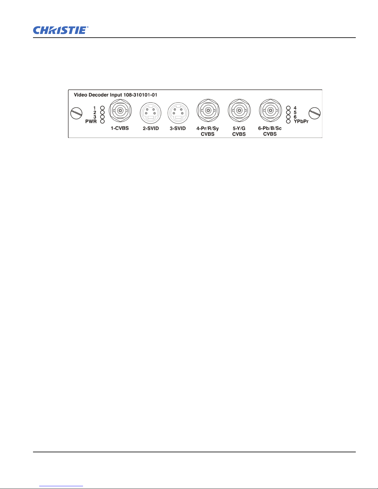
The video decoder Input card has 8 LED indicators. The PWR LED indicates that the module is installed
properly, and has been successfully configured. The YPbPr LED indicates that a valid component signal has
been detected on inputs 4, 5, and 6 (Component Input grouping must also be selected in the projector menu.
Refer to Section 3 Operation. The remaining LEDs are each associated with one of the inputs and indicate that
a valid signal has been detected on that input.
2.3 How Color Settings Interact in a Entero Array
Image Settings > Color Space tells the projector how to interpret video data coming in. See Color Space, on
page 3-21.
Image Settings > Advanced Image Settings > Color Settings adjusts the color temperature. Use ArrayLOC
color and color temperature settings instead. When enabled, ArrayLOC overrides the settings on the Color
Settings menu. See Color Settings, on page 3-29.
Configuration > Geometry & Color > Manual RGB Adjustment is the manual way to set the levels of each
LED. These adjustments are available when ArrayLOC is OFF or set to Fixed mode. When ArrayLOC is set to
Cool or Bright mode, LED levels are controlled by ArrayLOC function automatically.
Configuration > ArrayLOC > Array Color Target tells the projector what you expect to see on the screen.
This is the recommended way to control the color space for the projector and array. See Array Color Target,
on page 3-43. This menu is also available under Configuration > Geometry & Color.
Configuration > ArrayLOC > Projector Color Adjustment lets you adjust each projector output so that it
represents the color target. Adjustments compensate for projector-to-projector differences and for the
projection system as a whole, including loss of brightness or color shift due to lens, mirror, and screen. For
example the mirror might not reflect blue 100 percent, or the screen might absorb more blue. You can measure
the output at the screen with a color meter and use this option to increase the blue until you get the array color
target value at the screen. See Projector Color Adjustment, on page 3-43. This menu is also available under
Configuration > Geometry & Color.
Configuration > ArrayLOC > Projector Color Adjustment > White Brightness Adjustment lets you turn
the brightness target adjustment into a meaningful number, for example a number that relates to Ft-L.
Section 2: Setting Up a Source
Entero RPMWU/RPMSP/RPMHD-LED01 User Manual 2-5
020-100367-05 Rev. 1(06-2012)

Section 2: Setting Up a Source
2.4 Optimizing the Projectors for the Source
1. Select Image Orientation in the Configuration > Output Settings menu, and change the orientation of
the displayed image to suit the installation. For example, for Christie cube installations, select Rear
Projection Inverted.
2. Assign a unique projector ID number for each projector.
3. If the projectors are connected serially, enable Broadcast Key in the Communications menu. This allows
you to switch between communicating with one or all projectors.
4. Display the source to optimize.
5. Select Auto Setup to give the projector a chance to setup the best possible settings for the chosen
incoming signal.
6. Make sure that the Processing Mode (Image Settings menu) is correct for the selected source.
7. Change Resize Presets if you want the image displayed at a resolution other than native.
8. For analog sources, adjust Pixel Phase and Pixel Tracking from the Size and Position menu to eliminate
noise from the displayed image.
9. ArrayLOC automatically adjusts projector colors and brightness. Ensure that ArrayLOC is enabled.
10. If required, adjust image Blacklevels and Input Levels.
11. If required, optimize Projector Color and Brightness, see Managing Colors with ArrayLOC on page-3-55.
12. If required, adjust brightness uniformity, see Adjust Brightness Uniformity on page-3-40.
2-6 Entero RPMWU/RPMSP/RPMHD-LED01 User Manual
020-100367-05 Rev. 1 (06-2012)

3 Operation
Refer to Safety Warnings and Guidelines in 5 Maintenance.
This section describes the controls and switches used for basic projector operation once it is properly installed,
aligned, and configured by a Christie accredited service technician. You can access projector controls and
settings with the standard IR remote, or with laptop using the web interface. This chapter focuses on the use of
the remote and the projector menus. For information about access the same functionality through the web
interface, refer to Appendix B: Web User Interface.
3.1 Using the IR Remote
Laser radiation is emitted from the laser diode in the remote. Do not look
directly into the laser beam.
The standard IR remote can be used as a wired or wireless control. Under optimal conditions, the wireless
keypad can communicate with a projector over a 100 foot distance. In wireless mode, the standard IR remote
communicates with the projector with a battery-powered infrared (IR) transmitter.
Use the standard IR remote the same way you would use a remote control supplied with a TV or DVD player.
When pressing a function key, direct the standard IR remote toward the projector’s front IR sensor. The IR
sensor on the projector will detect the signal and relay the commands for internal processing. A laser pointer is
built into the standard IR remote. Refer to 3.1.1 IR Remote, on page 3-2.
Section 3: Operation
Keep these guidelines in mind:
• Press keys one-at-a-time; there are no simultaneous key combinations required.
• NOTE: To use Power, Shutter, and OSD functions, press the appropriate button, and then press the UP
arrow to switch ON or the DOWN arrow to switch OFF: You can also press-and-hold the appropriate button
for 2 seconds, or press it twice quickly. Refer to 3.1.1 IR Remote, on page 3-2.
• Arrow keys are held down for continuous adjustment/movement in the related key direction.
• NOTE: In serial networks, pause briefly between adjustments to make sure that more distant projectors can
“keep up” with the commands. If you press a key while the projector is still responding to the previous
action, such as during power-up, the second key press may not take effect.
•Refer to 3.1.1 IR Remote, on page 3-2 for the description of those keys provided on the standard IR remote
keypad.
Entero RPMWU/RPMSP/RPMHD-LED01 User Manual 3-1
020-100367-05 Rev. 1 (06-2012)

Section 3: Operation
3.1.1 IR Remote
3-2 Entero RPMWU/RPMSP/RPMHD-LED01 User Manual
020-100367-05 Rev. 1 (06-2012)

3.1.2 Wired Remote
You can convert the standard IR remote into a wired remote using the optional cable. Connect one end into the
standard IR remote, and the other to the XLR connector labeled Remote on the Electronics Module. The
wired remote is recommended when the lighting conditions are unsuitable for proper IR transmission.
To use the wired remote, make sure that wired remote support is enabled on the projector the remote is
connected to: Main Menu > Configuration > Communications > Wired Keypad Enabled.
To use the wired remote to control multiple projectors in an ArrayLOC network, ensure that wired remote
support is enabled on the controlling projector, and make sure that key synchronization is enabled on the
controlling projector and on all the receiving projectors: Main Menu > Configuration > ArrayLOC >
ArrayLOC Configuration > Synchronize Keys, Test Pattern, Color Enable.
NOTE: Batteries are not required for the wired remote projector control to operate; however, if the laser
pointer is required batteries must be installed in the remote.
3.1.3 IR Remote Commands
Specific keypad commands are explained.
The projector is a class 2M source of visible LED radiation. Directly viewing the
LED output with certain optical instruments (for example, eye loupes, magnifiers and
microscopes) within a distance of 100 mm (3.94”) may pose an eye hazard.
Section 3: Operation
Power ON/OFF
Press and hold POWER for 2 seconds or press twice quickly to power the projector ON or OFF. Or, press and
release POWER followed immediately by the UP arrow key (ON) or DOWN arrow key (OFF) to guarantee
that the correct action is initiated. This is useful if you are unsure of the present state of the projector.
Tes t
Steps forward through all internal test patterns. After stepping past the last test pattern, you will return to
current input. Press TEST and then cycle by using the LEFT or RIGHT arrow keys, to cycle in either direction
through the test patterns. Press EXIT to return to the current input.
Auto
Initiates an automated process in which the projector optimizes critical display parameters such as size,
position, pixel tracking, etc., for the current source. These parameters are listed in Tab le 3 .1 . An auto setup can
save time in perfecting a display, and you can modify the adjustments as desired.
Table 3.1 Auto Setup
OPTIMIZES SETS TO DEFAULT
Pixel Tracking Contrast
Pixel Phase Brightness
Size and Blanking Auto Input Level (OFF)
Vertical Stretch Detail (if video source)
Position Filter
Input Levels Luma Delay
Entero RPMWU/RPMSP/RPMHD-LED01 User Manual 3-3
020-100367-05 Rev. 1 (06-2012)

Section 3: Operation
NOTE: You must have an unlocked channel present to use Auto Setup.
The best Auto Setup will be obtained under the following conditions:
• Input levels: It is best to have an image with saturated (very bright) colors.
• Phase: High contrast edges are needed.
To determine Active Window size:
• Video images should have whites and blacks in the image.
• Wide range video images should have content (including white) that extends to all edges of the image.
Channel
Select a specific source setup (channel) defined and stored in projector memory. Once you hit the CHANNEL
key and enter a two-digit channel number (or, if there is a list displayed, highlight it and press ENTER), the
display will automatically change and update according to the numerous setup parameters defined for that
channel. For more information about channels, inputs, and slots, see 3.3 Using Inputs and Channels, on page
3-10.
NOTE: A new channel is automatically created if you adjust an image from a new source. 2) Channel key
behavior during a presentation depends on whether or not the Display Channel List option is enabled in the
Menu Preferences menu. You can choose to use a scrollable list of channels when you press Channel, or you
may prefer to enter the desired channel number “blind”, i.e., without on-screen feedback. See Menu
Preferences discussed later in this section.
Slot 1, 2, 3, 4
Press a
INPUT on the card. Press a different SLOT key to select a different input card. For more information about
SLOT key to select the input card in that slot. Press the SLOT key again to display the next active
channels, inputs, and slots, see 3.3 Using Inputs and Channels, on page 3-10.
Input
Displays all inputs in all slots, both Active and Inactive. Press INPUT once and scroll through the list to select
an Input for the main image. Press INPUT again to show the list, and select the secondary image. For more
information about channels, inputs, and slots, see 3.3 Using Inputs and Channels, on page 3-10.
PIP
Switches the secondary image (Picture-In-Picture or Picture-By-Picture) ON or OFF.
Swap
Swaps the main and secondary images.
Contrast
Changes the level of peak white in your images. Use LEFT/RIGHT arrow key until you reach the desired level
of contrast. For best results, start low and increase so that whites remain bright, but are not distorted or tinted,
and that light areas do not become fully white (i.e., “crushed”). Conversely, low contrast causes dim images.
3-4 Entero RPMWU/RPMSP/RPMHD-LED01 User Manual
020-100367-05 Rev. 1 (06-2012)

Section 3: Operation
Bright
Increases or decreases the black level in the image. Use LEFT/RIGHT arrow key until you reach the desired
level of brightness. For best results, start high and decrease so that dark areas do not become fully black (i.e.,
“crushed”). Conversely, overly high brightness changes black to dark grey, causing washed-out images.
Gamma
Determines how grey shades are displayed between minimum input (black) and maximum input (white) for a
given amount of signal. The proper setting helps maintain optimized blacks and whites while ensuring a
smooth transition for the “in-between” values utilized in greys. Unlike brightness and contrast controls, the
overall tone of an image can be lightened or darkened without changing the two extremes, and your images
will be more vibrant yet with good detail in dark areas when using the Gamma control.The nominal setting for
Gamma Correction of 0 is correct for most signals and conditions. If excess ambient light washes out the
image and it becomes difficult or impossible to see details in dark areas, increase the gamma correction setting
to compensate.
Number Keys
Press 1 to 9 to enter a value in a text box or to select a menu item.
10+
Press 0 (zero) before pressing another number to enter a number greater than 9. For example, press 0 (zero),
then 2 to enter the number 12 as a menu selection.
NOTE: When entering numbers in a text field, the 0 (zero) button only acts as zero. See 3.2.5 Editing Text, on
page 3-9.
Help
Press HELP to display context-sensitive help. Press HELP again to close the Help window.
Menu
Press MENU to enter or exit the projector’s menu system.
OSD (On-screen display)
Press OSD and then the DOWN arrow to hide the projector’s menu system during use.
To see the menus again, do one of the following:
• Press and hold OSD for 2 seconds.
• Press and release OSD followed immediately by the UP arrow.
•Press OSD twice
Invisible menus are fully functional, enabling “hidden” access to numbered features and image adjustments by
entering the corresponding sequence of key presses on the IR remote keypad.
NOTE: With OSD “ON”, you can still hide error messages and slidebars by disabling these options in the
Menu Preferences menu (Main Menu > Configuration).
Entero RPMWU/RPMSP/RPMHD-LED01 User Manual 3-5
020-100367-05 Rev. 1 (06-2012)

Section 3: Operation
Figure 3-1 Function Key
Shutter
The shutter is open upon power-up. Press and hold SHUTTER to move between simulated shutter states in the
order; OPEN-CLOSED-WHITE-OPEN. Or, press and release SHUTTER followed immediately by UP arrow
key (Closed) or DOWN arrow key (Open) to guarantee the correct state.
Close the shutter to block the displayed image while maintaining access to projector functions.
The white shutter state allows you to view menus and images if RGB brightness is set to 0. The LED status
display shows SH when the shutter is in either black or white modes.
Function Key
In a Numeric Field in a Menu: Use FUNC to enter a negative number.
In a Text Field: Press FUNC followed by:
• the UP arrow key or DOWN arrow key to convert between capital and lowercase letters.
• the LEFT arrow key or RIGHT arrow key to insert or delete a character.
• the ENTER to delete all characters.
Within a Presentation: Press FUNC followed by 2 numeric numbers to
enable a specific color or colors in the display (see right). For example,
Eliminating one or more colors can help with certain diagnostics and setups,
such as when accurately overlaying one image on top of another from stacked
projectors.
will display only red, and will display green data.
NOTE: Color enabling can also be implemented from numerous locations
within the menu system.
Press F
UNC followed by HELP to disable Keystone, Edge Blending and Brightness Uniformity settings. This
will disable the features without changing the settings associated with them.
Proj
Press P
ROJ to access a specific projector within a group of projectors or to confirm if the local projector is
listening. The number in the “Enter Number” window indicates which projector is currently listening to
commands and will match the projector address defined in the Configuration > Communications menu. The
Proj check box (read-only) shows whether or not the projector physically connected to a remote is listening to
commands from that remote. A checkmark means that connected projector is listening; if there is no
checkmark, you are communicating with a different projector.To control a specific projector with the keypad,
press P
ROJ and then enter the 3-digit number assigned to the projector you want to use. If you switch to a
projector other than the one you are currently using, the checkmark will disappear. To broadcast to multiple
projectors, press P
ROJ and then PROJ again without entering a projector number. Keypad commands will then
affect all projectors present.
NOTE: The projector address can be set in the Configuration > Communications menu.
Enter
Press E
NTER to select a highlighted item, to toggle a check box, or to accept a parameter adjustment and return
to the previous menu or image.
3-6 Entero RPMWU/RPMSP/RPMHD-LED01 User Manual
020-100367-05 Rev. 1 (06-2012)

Exit
LASER RADIATION
DO NOT STARE INTO BEAM
LASER DIODE
Wavelength 670nm
Max Output 1mW
CLASS II LASER PRODUCT
CAUTION
Section 3: Operation
Press E
NOTE: E
XIT to return to the previous level (the previous menu).
XIT does not save changes within text editing boxes (including number editing of a slide bar value)
or within drop-down lists. It acts as a “cancel” in these cases.
Arrow Keys
Use the L
EFT/RIGHT arrow key to change a slide bar value or to select a different option within a drop-down
list without having to first scroll through options or navigate within a menu, drop-down list, or text box.
Laser
Press and hold L
ASER to activate the laser pointer on the remote. Point
the remote at the screen to highlight an area of your presentation. The
L
ASER pointer requires batteries in the wired remote in order to work.
3.2 Navigating the Menus
3.2.1 Main Menu
Most of the projector controls are accessed from within the projector
menu system. There are several groups of related functions, with each
group selectable from the Main Menu. Press M
this Main Menu.
ENU at any time to display
On the remote keypad, enter the number corresponding to the function
menu you wish to access, such as 2 for the Image Settings menu. Or use
P/DOWN arrow key on any keypad to highlight the desired option,
the U
then press E
NTER. The corresponding function menu or drop-down list of
further options will appear.
With a function menu displayed, enter a menu option number for any numbered option, or use the U
arrow key to highlight the desired option and then press E
NTER.
P/DOWN
Long menus have a scroll bar on the right—use the arrow keys to access the remainder of the menu. Locked
items or items that do not pertain to the current action or condition appear dimmed and cannot be selected.
When finished with a function menu:
•Press E
XIT to return to the previous screen.
OR
•Press M
ENU to leave the menu system and return to the presentation.
NOTES: 1) If there is no signal present, all source-dependent adjustments are disabled. 2) After 15 minutes of
inactivity, the projector exits the menus and returns to the presentation. 3) The Status menu is read-only.
Entero RPMWU/RPMSP/RPMHD-LED01 User Manual 3-7
020-100367-05 Rev. 1 (06-2012)

Section 3: Operation
Figure 3-2 Slide Bar
Example
3.2.2 On-line Help
Press HELP to display summary information about the current menu or highlighted option. Press HELP again to
exit.
3.2.3 The Global Icon
Menu options that include this icon apply universally. Menu options without this icon apply to the
selected channel only.
3.2.4 Using Slide bars and Other Controls
Most of the function menus allow you to change settings by using slide bars, check boxes, and drop-down lists.
Navigating options:
Enter the menu option number corresponding to the setting you wish to change (for example, press M
ENU 1 3
to select “Vertical Stretch” in the Size and Position menu).
• Move the highlight to the option desired and press E
• Move the highlight to the option desired and press L
NTER.
EFT/RIGHT arrow key to adjust immediately. Both the
number and the length of the bar change accordingly. See Figure 3-2. Hold for continuous adjustment.
• You can bypass the menus entirely and use a single key to immediately access an adjustment during your
presentation (applies only to options having their own key, such as C
ONTRAST, BRIGHT, GAMMA, etc.).
• For “blind” access, hide the entire menu system (see OSD (On-screen display), on page 3-5) and access
using the proper sequence of key presses.
Slide bars in menus: The current value for a given parameter, such as size or
vertical stretch, appears to the left of its slide bar icon (adjustment window). This
number often expresses a percentage, or it may have units associated with it (such
as pixels), depending on the specific option.
Press L
EFT/RIGHT arrow key to gradually adjust the setting up or down—both the
number and the length of the bar change accordingly. Hold for continuous adjustment.
Press E
save (or press E
NTER to activate a slide bar text box for specific number entry via the keypad and then press ENTER to
XIT to cancel).
“Direct” slide bars: For quick access, to Gamma, Brightness, and Contrast slide bars without traveling the
menu system. Press G
to adjust a direct slide bar, or press E
A
RROW key or RIGHT arrow key to save (or EXIT to cancel). When you are done, press EXIT to save and return
AMMA, BRIGHTNESS, or CONTRAST to display the contrast slide bar. Use the arrow keys
NTER and enter a specific number from the keypad, then ENTER or LEFT
to your presentation.
3-8 Entero RPMWU/RPMSP/RPMHD-LED01 User Manual
020-100367-05 Rev. 1 (06-2012)

Section 3: Operation
Figure 3-3 Check Box
Example
NOTES: 1) You can still adjust a direct slide bar as usual if the display is turned OFF (see OSD or Menu
Preferences menu) — the slide bar won’t be visible. 2) A direct slide bar disappears if it is not used within five
seconds.
Check boxes: A conditions is present if its adjacent check box contains a
checkmark. To toggle the check box, highlight and press E
and use R
IGHT arrow key to check and LEFT arrow key to uncheck. If a check
NTER, or highlight
box is numbered, enter its number to immediately toggle the check box.
Drop-down lists: To see a list of options available for a given parameter:
• Highlight the list and press E
• Enter the menu option number
• Use the U
P arrow key or DOWN arrow key to navigate up and down within the list. Press ENTER to choose an
option from the list.
• To quickly scroll through a list without first pulling it down, highlight the option and use L
IGHT arrow key. Press ENTER when the desired choice appears.
R
NOTES: 1) Press L
list. 2) Press E
3.2.5 Editing Text
Activate the Edit Window: To enter or edit text, highlight the desired parameter (such as a channel name) and
press E
character highlighted in a square cursor, signifying that this character is ready for editing.
Navigate Within the Edit Window: Press R
the cursor forward or L
desired.
Edit a character: To edit a highlighted character, use U
and D
and punctuation available. When the character you need is highlighted,
press R
available character of current text.
NTER to activate its adjacent edit window. Any previously entered text is displayed with its first
OWN arrow key to scroll through the alphabet, numbers, spaces
IGHT arrow key to select it. The cursor will move to the next
NTER; or
EFT arrow key or
EFT arrow key or RIGHT arrow key to jump between pages in an extra long drop-down
XIT while in a drop-down list to cancel any change.
IGHT arrow key to move
EFT arrow key to move the cursor backwards as
P arrow key
Change Case: To convert a lower case letter to a capital letter, position on the letter and press F
by the U
and press F
P arrow key simultaneously. To convert a capital letter into a lower case letter, position on the letter
UNC followed by the DOWN arrow key.
Add or Delete a Character or Space: To insert a space at the cursor location, press F
arrow key simultaneously. To delete a highlighted character (or space), press F
simultaneously.
Delete all Characters: Press F
Entero RPMWU/RPMSP/RPMHD-LED01 User Manual 3-9
020-100367-05 Rev. 1 (06-2012)
UNC followed
UNC then the RIGHT
UNC then the LEFT arrow key
UNC followed by ENTER.

Section 3: Operation
Press ENTER When Finished: To accept edits and leave the edit window, press ENTER.
NOTE: Press E
XIT at any time to cancel changes and return to the previously-defined text.
Edit numerical values: Enter numbers directly from the keypad to specify numbers representing projector
channels (source setups), or slots. As each digit is entered, it is inserted on the right of the field, and the
numbers already in the field are shifted to the left.
Channel numbers are defined with 2 digits—for example, if you enter only a single digit (such as “7”) for a
channel number, the channel will automatically be defined as “07”. Enter “07” to use this channel. If you press
any non-numbered key, the number entered up to that point is accepted and updated as the new value. Press
E
XIT to cancel editing of numerical values.
3.3 Using Inputs and Channels
The projector allows you to define, store and recalls up to 99 different channels (customized setups or
configurations) for a variety of inputs. Depending on what you have defined, each physical source connection
(i.e., input at the projector) can have several different channels associated with it.
• Slot refers to an input card installed in the projector. There are 4 Input card slots.
• Input refers to both the physical connector on the Input card and to the media source connected to it. Each
Input card can have one or more inputs.
• Channel refers to the setup parameters for a media source input. The parameters include the Slot and Input,
Input type, and Input resolution.
NOTE: See Section 2 Setting Up a Source, for a full explanation of how to connect sources to the projector.
3.3.1 Inputs
An input is a source physically connected to the projector. Input describes the source signal and which input
slot it is connected to.
Switching Inputs
To select an input using the IR remote:
• Press the I
slot. The currently selected input for the main image will be highlighted. Scroll up or down through the list
and press E
for the PIP image. Repeatedly pressing the I
• Press the appropriate
Main image. Press
only applicable for the Main image.
NPUT key. This will display a list of the four slots, with the card type and input signal type in each
NTER to make a new selection. Press the INPUT key again to show the list and allow the selection
NPUT key will toggle between the main and PIP image.
SLOT key (1-4) to quickly display one of the 4 Inputs connected to the projector for the
SLOT again to select a different Input. This will not display any menu selection, and is
3-10 Entero RPMWU/RPMSP/RPMHD-LED01 User Manual
020-100367-05 Rev. 1 (06-2012)
 Loading...