

Christie E600 User Manual

User Guide
020-102717-02
Christie E600 LED Display
Controller

NOTICES
COPYRIGHT AND TRADEMARKS
yright © 2018 Christie Digital Systems USA Inc. All rights reserved.
Cop
All brand names and product names are trademarks, registered trademarks or trade names of their respective holders.
GENERAL
Every effort has been made to ensure accuracy, however in some cases changes in the products or availability could occur which may not be reflected in this
document. Christie reserves the right to make changes to specifications at any time without notice. Performance specifications are typical, but may vary
depending on conditions beyond Christie's control such as maintenance of the product in proper working conditions. Performance specifications are based on
information available at the time of printing. Christie makes no warranty of any kind with regard to this material, including, but not limited to, implied
warranties of fitness for a particular purpose. Christie will not be liable for errors contained herein or for incidental or consequential damages in connection
with the performance or use of this material. Canadian manufacturing facility is ISO 9001 and 14001 certified.
WARRANTY
Products are warranted under Christie’s standard limited warranty, the complete details of which are available by contacting your Christie dealer or Christie. In
addition to the other limitations that may be specified in Christie’s standard limited warranty and, to the extent relevant or applicable to your product, the
warranty does not cover:
Problems or damage occurring during shipment, in either direction.
a.
Problems or damage caused by combination of a product with non-Christie equipment, such as distribution systems, cameras, DVD players, etc., or use
b.
of a product with any non-Christie interface device.
Problems or damage caused by misuse, improper power source, accident, fire, flood, lightning, earthquake, or other natural disaster.
c.
Problems or damage caused by improper installation/alignment, or by equipment modification, if by other than Christie service personnel or a Christie
d.
authorized repair service provider.
Use of third party product enclosures for environmental protection during outside use must be approved by Christie.
e.
Problems or damage caused by use of a product on a motion platform or other movable device where such product has not been designed, modified or
f.
approved by Christie for such use.
Except where the product is designed for outdoor use, problems or damage caused by use of the product outdoors unless such product is protected from
g.
precipitation or other adverse weather or environmental conditions and the ambient temperature is within the recommended ambient temperature set
forth in the specifications for such product.
Defects caused by normal wear and tear or otherwise due to normal aging of a product.
h.
The warranty does not apply to any product where the serial number has been removed or obliterated. The warranty also does not apply to any product sold
by a reseller to an end user outside of the country where the reseller is located unless (i) Christie has an office in the country where the end user is located or
(ii) the required international warranty fee has been paid.
The warranty does not obligate Christie to provide any on site warranty service at the product site location.
PREVENTATIVE MAINTENANCE
Preventative maintenance is an important part of the continued and proper operation of your product. Failure to perform maintenance as required, and in
accordance with the maintenance schedule specified by Christie, will void the warranty.
REGULATORY
The product has been tested and found to comply with the limits for a Class A digital device, pursuant to Part 15 of the FCC Rules. These limits are designed
to provide reasonable protection against harmful interference when the product is operated in a commercial environment. The product generates, uses, and
can radiate radio frequency energy and, if not installed and used in accordance with the instruction manual, may cause harmful interference to radio
communications. Operation of the product in a residential area is likely to cause harmful interference in which case the user will be required to correct the
interference at the user’s own expense.
CAN ICES-3 (A) / NMB-3 (A)
이 기기는 업무용(A급)으로 전자파적합등록을 한 기기이오니 판매자 또는 사용자는 이점을 주의하시기 바라며, 가정 외의 지역에서 사용하는 것을 목적으로 합니다.
ENVIRONMENTAL
The product is designed and manufactured with high-quality materials and components that can be recycled and reused. This symbol
and electronic equipment, at their end-of
to local regulations. In the European Union, there are separate collection systems for used electrical and electronic products. Please help us to conserve the
environment we live in!
-life, should be disposed of separately from regular waste. Please dispose of the product appropriately and according
means that electrical

Content
Product overview..................................................5
E600 controller
FE600 controller extender interface and ports................................7
Connecting the FE600 fiber optic extender to power............................9
Terminology.......................................................9
Product documentation................................................9
Related documentation.............................................10
Configuring the array.............................................. 11
Installing/Accessing the E600 controller software...............................11
Logging into the controller software.......................................11
Setting the input resolution............................................11
Identify the screen cabling path......................................... 12
Adjusting the initial picture coordinates.....................................13
Adjusting the image brightness..........................................13
Adjusting the image quality............................................14
Setting the redundancy backup..........................................14
Testing the communication between the controller and tiles........................14
Reviewing the tile configuration..........................................15
Loading a cabinet configuration file....................................... 15
Adjusting dark and light lines between tiles.................................. 16
Displaying a picture when there is no signal..................................16
Changing the display to black when there is no signal............................17
Restoring the factory settings...........................................17
Locking and unlocking the controller.......................................17
Color matching LED modules........................................... 18
Calibrating replacement LED modules......................................18
Configuring HDR...................................................19
interface and ports........................................ 5
Monitoring Velvet Apex with SNMP....................................20
MIB traps....................................................... 20
Troubleshooting..................................................22
Line adjustments do not appear on the module edges............................22
Text displays beyond the button outline.....................................22
Christie E600 LED Display Controller User Guide 3
020-102717-02 R
Copyright © 2018 Christie Digital Systems USA, Inc. All rights reserved.
ev. 1 (10-2018)

Content
An image remains on the display after I disconnect the source...................... 22
Christie E600 LED Display Controller User Guide 4
020-102717-02 R
Copyright © 2018 Christie Digital Systems USA, Inc. All rights reserved.
ev. 1 (10-2018)
Product overview
V
elvet Apex tiles are modular, high-quality image display units that can be configured to achieve an
HD display, depending on the pixel pitch of the tile being installed.
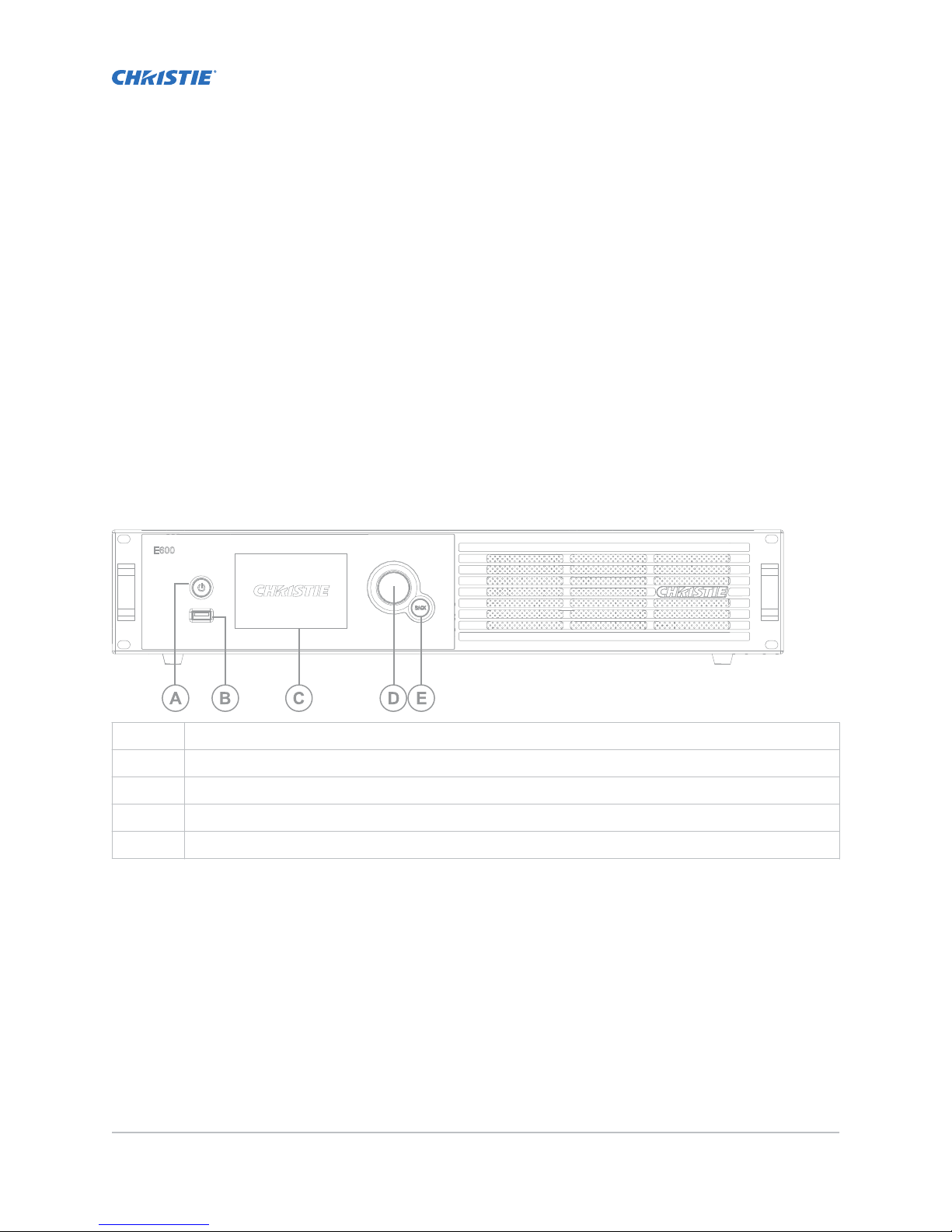
E600 controller interface and ports
Learn about the interface and physical ports on the E600 controller.
The E600 controller behaves as two independent controllers, displaying 3840 x 2160 pixels at 30 Hz
with each virtual controller. The images of both DVI1 and DVI2 input sources can be displayed on the
tiles simultaneously, but the inputs must be configured independently.
DVI1 corresponds to Ethernet ports 1-8, and DVI2 corresponds to Ethernet ports 9-16.
Front
A Power button
B USB interface for communication with a UDISK
C LCD screen
D Menu dial for interacting with the menu
E Back button for exiting from the current operation or option in the menu
Christie E600 LED Display Controller User Guide 5
020-102717-02 R
Copyright © 2018 Christie Digital Systems USA, Inc. All rights reserved.
ev. 1 (10-2018)

Product overview
Rear
Inputs/Outputs Description
A Outputs RJ45 (Qty. 16) 16-channel Gigabit Ethernet interface, with each channel
supporting up to 1G bandwidth
T
otal loading capacity: 8.8 million pixels
Low latency is not supported
B Control Ethernet USB, RJ45 (with SNMP support), and USB cascading
C USB Out
D USB In
E Genlock BNC (Qty. 2) Support Genlock IN & LOOP
F Inputs DisplayPort Standard DisplayPort 1.2 input
The maximum user-definable resolution is 7680 x 1080 @ 60Hz or
1080 x 6000 @ 60Hz.
G HDMI Standard HDMI 2.0 input
Supports 8 bit, 10 bit, and 12 bit; refer to the table below.
H DVI (Qty. 2) Dual-link DVI, user-definable resolution
• Horizontal resolution maximum: 3840 pixels
• Vertical resolution maximum 3840 pixels
I OPT Output Fiber optic ports for connecting to the FE600 fiber optic extender
J Power Power supply port: AC 100-240V~ 50/60hz
K Power switch
HDMI 8 bit, 10 bit, and 12 bit support
Christie E600 LED Display Controller User Guide 6
020-102717-02 R
Copyright © 2018 Christie Digital Systems USA, Inc. All rights reserved.
ev. 1 (10-2018)

Color depth Input source
Product overview
8 bit
10 bit
12 bit
3840 x 2160 @
60Hz (HDCP)
RGB444 Yes Yes Yes
YCbCr444 Yes Yes Yes
YCbCr422 Yes Yes Yes
YCbCr420 Yes Yes Yes
RGB444 No Yes Yes
YCbCr444 No Yes Yes
YCbCr422 Yes Yes Yes
YCbCr420 Yes Yes Yes
RGB444 No Yes Yes
YCbCr444 No Yes Yes
YCbCr422 Yes Yes Yes
YCbCr420 Yes Yes Yes
3840 x 1080 @
60Hz (HDCP)
1920 x 1080 @
60Hz (HDCP)
FE600 controller extender interface and ports
Learn about the interface and ph
Front
A Status display
ysical ports on the E600 controller.
Christie E600 LED Display Controller User Guide 7
020-102717-02 R
Copyright © 2018 Christie Digital Systems USA, Inc. All rights reserved.
ev. 1 (10-2018)

Rear
Product overview
Caution! If not a
voided, the following could result in minor or moderate injury.
• FIRE HAZARD! Always connect the Neutrik PowerCON cable to the device before connecting it to
the wall. The PowerCON connector is not intended to be hot pluggable.
• SHOCK HAZARD! Power supply uses double pole/neutral fusing.
Inputs/Outputs Description
A Outputs RJ45 (Qty. 16) 16-channel Gigabit Ethernet interface, with each channel
supporting up to 1G bandwidth
T
otal loading capacity: 8.8 million pixels
Low latency is not supported
B Control Ethernet USB, RJ45 (with SNMP support), and USB cascading
C USB In
D OPT Output (Qty. 4) Fiber optic ports for connecting to the E600 controller
• OPT1 is used for transferring the data of port 1-8
• OPT2 is used for transferring the data of port 9-16
• OPT3 is the backup channel of OPT1
• OPT4 is the backup channel of OPT2
Either Gigabit Ethernet port or optical fiber port can be used at the
same time, but cannot be used to connect devices simultaneously.
E Power IEC 60320-C18 power supply port: AC 100-240V~ 50/60hz
F Power switch
G Neutrik PowerCON power supply port: AC 100-240V~ 50/60hz
Christie E600 LED Display Controller User Guide 8
020-102717-02 R
Copyright © 2018 Christie Digital Systems USA, Inc. All rights reserved.
ev. 1 (10-2018)
 Loading...