

Christie DWU951, DXG1051, DWX951 User Manual

DWU951/DWX951/DXG1051
User's Manual (detailed)
Operating Guide - Technical
020-000664-01

1
DWU951/DWX951/DXG1051 User's Manual - Technical 020-000664-01 Rev. 1 (01-2014)
Projector
DWU951/DWX951/DXG1051
User's Manual (detailed)
Operating Guide – Technical
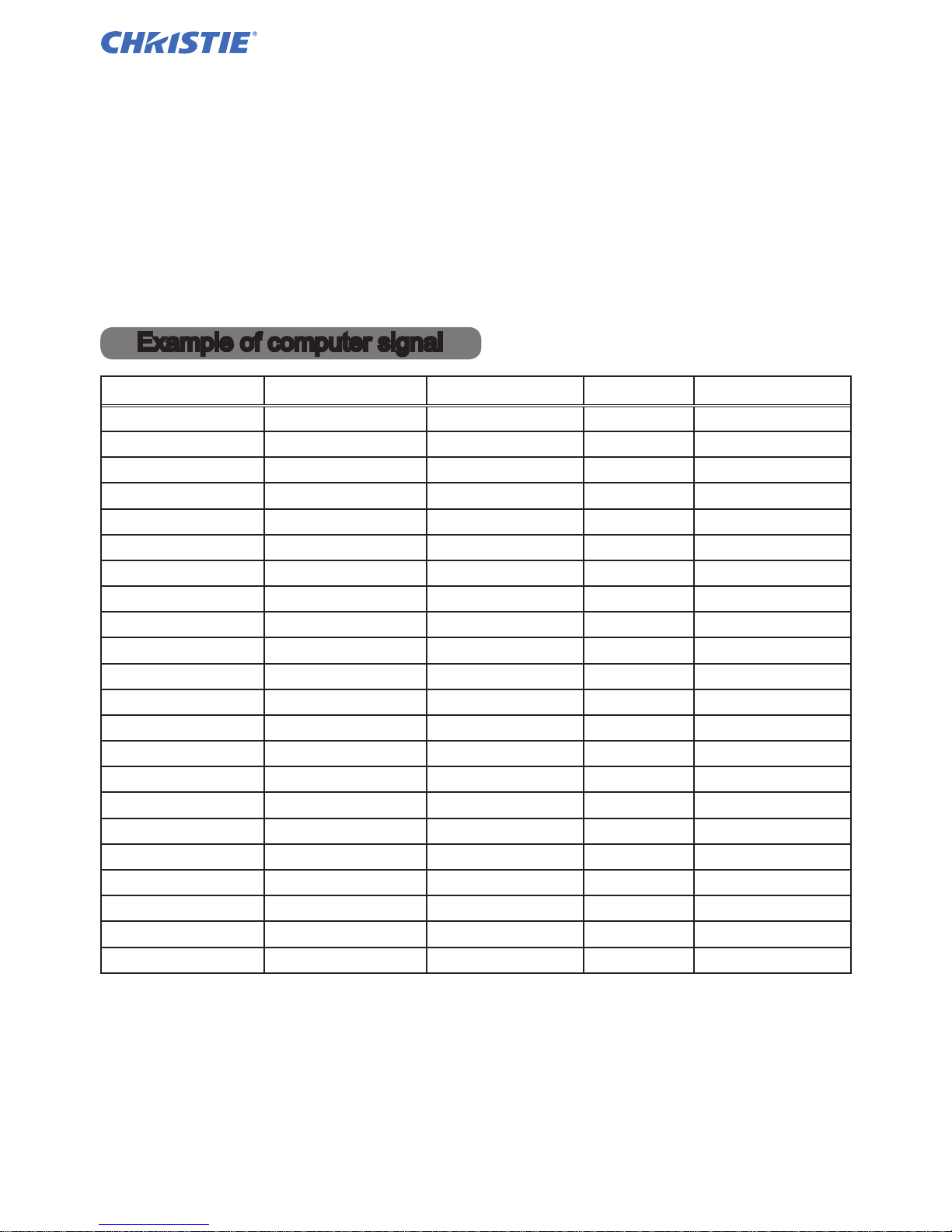
Resolution (H x V) H. frequency (kHz) V. frequency (Hz) Rating Signal mode
720 x 400
37.9 85.0 VESA TEXT
640 x 480 31.5 59.9 VESA VGA (60Hz)
640 x 480 37.9 72.8 VESA VGA (72Hz)
640 x 480 37.5 75.0 VESA VGA (75Hz)
640 x 480 43.3 85.0 VESA VGA (85Hz)
800 x 600 35.2 56.3 VESA SVGA (56Hz)
800 x 600 37.9 60.3 VESA SVGA (60Hz)
800 x 600 48.1 72.2 VESA SVGA (72Hz)
800 x 600 46.9 75.0 VESA SVGA (75Hz)
800 x 600 53.7 85.1 VESA SVGA (85Hz)
832 x 624 49.7 74.5 Mac 16” mode
1024 x 768 48.4 60.0 VESA XGA (60Hz)
1024 x 768 56.5 70.1 VESA XGA (70Hz)
1024 x 768 60.0 75.0 VESA XGA (75Hz)
1024 x 768 68.7 85.0 VESA XGA (85Hz)
1152 x 864 67.5 75.0 VESA
1152 x 864 (75Hz)
1280 x 768 47.7 60.0 VESA W-XGA (60Hz)
1280 x 800 49.7 60.0 VESA
1280 x 800 (60Hz)
1280 x 960 60.0 60.0 VESA
1280 x 960 (60Hz)
1280 x 1024 64.0 60.0 VESA SXGA (60Hz)
1280 x 1024 80.0 75.0 VESA SXGA (75Hz)
1440 x 900 55.9 59.9 VESA WXGA+ (60Hz)
Example of computer signal
2
DWU951/DWX951/DXG1051 User's Manual - Technical 020-000664-01 Rev. 1 (01-2014)
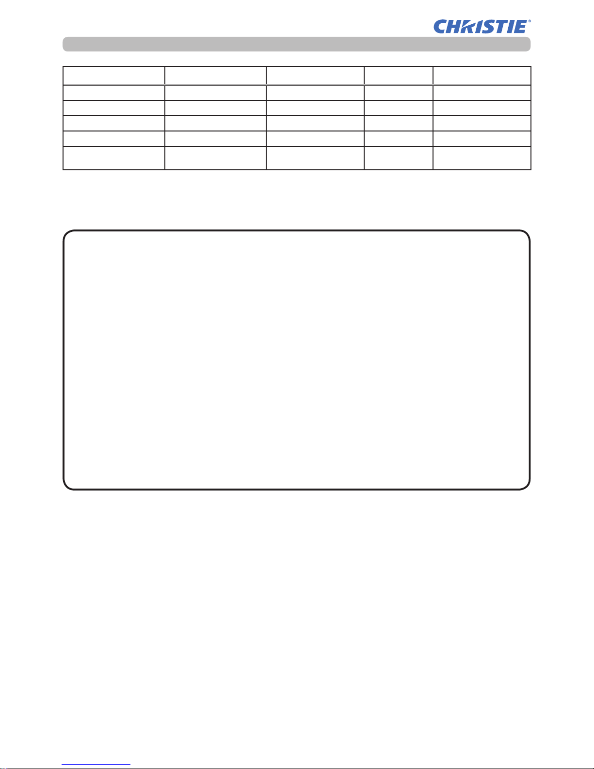
Example of computer signal
Resolution (H x V) H. frequency (kHz) V. frequency (Hz) Rating Signal mode
*1 1280 x 1024 91.1 85.0 VESA SXGA (85Hz)
*2 1400 x 1050 65.2 60.0 VESA SXGA+ (60Hz)
*3 1680 x 1050 65.3 60.0 VESA WSXGA+ (60Hz)
*1 1600 x 1200 75.0 60.0 VESA UXGA (60Hz)
*4 1920 x 1200 74.0 60.0 VESA
W-UXGA (60Hz)
Reduced Blanking
*1) Supported except for HDMITM input.
*2) Only for DXG1051.
*3)
Only for DWX951 and DWU951.
*4) Only for DWU951, but except for HDMITM input.
NOTE • Be sure to check jack type, signal level, timing and resolution before
connecting this projector to a computer.
• Some computers may have multiple display screen modes. Use of some of
these modes will not be possible with this projector.
• Depending on the input signal, full-size display may not be possible in some
cases. Refer to the number of display pixels above.
• Although the projector can display signals with a resolution up to UXGA
(1600x1200) or up to W-UXGA (1920x1200) for DWU951, the signal will be
converted to the projector’s panel resolution before being displayed. The best
display performance will be achieved if the resolutions of the input signal and
projector panel are identical.
• Automatic adjustment may not function correctly with some input signals.
• The image may not be displayed correctly when the input sync signal is a
composite sync or a sync on G.
• The illustrations in this manual are for illustrative purposes. They may differ
slightly from your projector.
3
DWU951/DWX951/DXG1051 User's Manual - Technical 020-000664-01 Rev. 1 (01-2014)
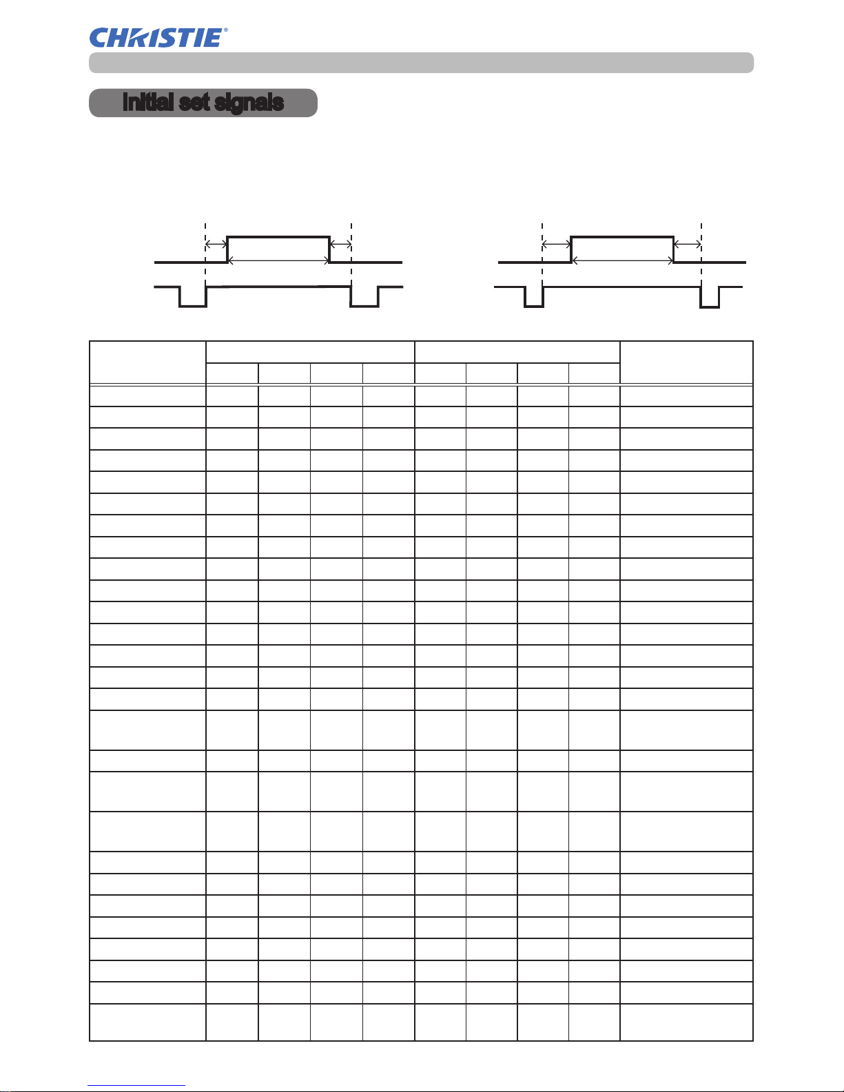
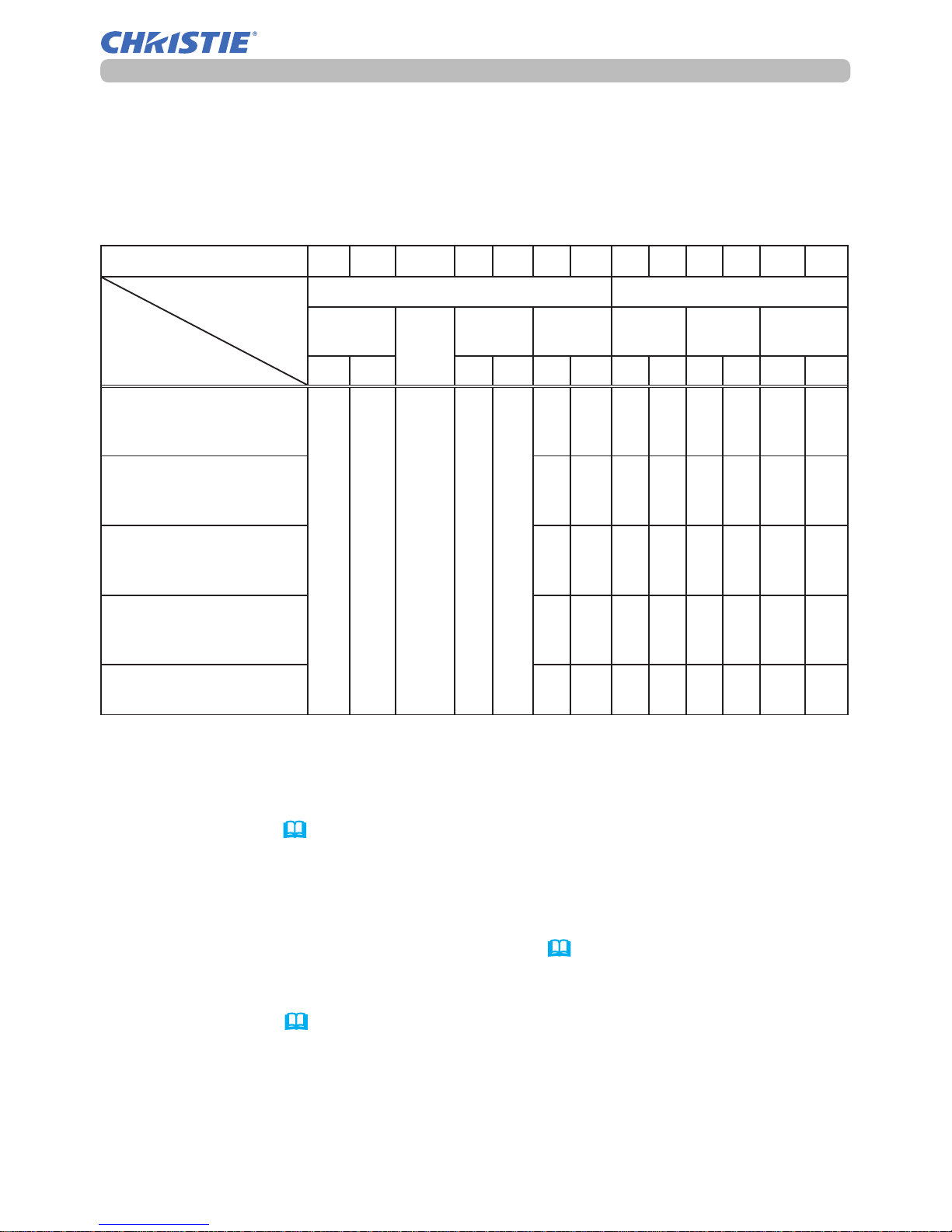
Initial set signals
Back porch (B) Front porch (D) Back porch (b) Front porch (d)
Active video (C)
Data Data
H. Sync. V. Sync.
Sync (A) Sync (a)
Active video (c)
Resolution
(H x V)
Horizontal signal timing (μs) Vertical signal timing (lines)
Signal mode
(A) (B) (C) (D) (a) (b) (c) (d)
720 x 400
2.0 3.0 20.3 1.0 3 42 400 1 TEXT
640 x 480 3.8 1.9 25.4 0.6 2 33 480 10 VGA (60Hz)
640 x 480 1.3 4.1 20.3 0.8 3 28 480 9 VGA (72Hz)
640 x 480 2.0 3.8 20.3 0.5 3 16 480 1 VGA (75Hz)
640 x 480 1.6 2.2 17.8 1.6 3 25 480 1 VGA (85Hz)
800 x 600 2.0 3.6 22.2 0.7 2 22 600 1 SVGA (56Hz)
800 x 600 3.2 2.2 20.0 1.0 4 23 600 1 SVGA (60Hz)
800 x 600 2.4 1.3 16.0 1.1 6 23 600 37 SVGA (72Hz)
800 x 600 1.6 3.2 16.2 0.3 3 21 600 1 SVGA (75Hz)
800 x 600 1.1 2.7 14.2 0.6 3 27 600 1 SVGA (85Hz)
832 x 624 1.1 3.9 14.5 0.6 3 39 624 1 Mac 16" mode
1024 x 768 2.1 2.5 15.8 0.4 6 29 768 3 XGA (60Hz)
1024 x 768 1.8 1.9 13.7 0.3 6 29 768 3 XGA (70Hz)
1024 x 768 1.2 2.2 13.0 0.2 3 28 768 1 XGA (75Hz)
1024 x 768 1.0 2.2 10.8 0.5 3 36 768 1 XGA (85Hz)
1152 x 864 1.2 2.4 10.7 0.6 3 32 864 1
1152 x 864
(75Hz)
1280 x 768 1.7 2.5 16.0 0.8 3 23 768 1 W-XGA (60Hz)
1280 x 800 1.6 2.4 15.3 0.8 3 24 800 1
1280 x 800
(60Hz)
1280 x 960 1.0 2.9 11.9 0.9 3 36 960 1
1280 x 960
(60Hz)
1280 x 1024 1.0 2.3 11.9 0.4 3 38 1024 1 SXGA (60Hz)
1280 x 1024 1.1 1.8 9.5 0.1 3 38 1024 1 SXGA (75Hz)
1280 x 1024 1.0 1.4 8.1 0.4 3 44 1024 1 SXGA (85Hz)
1400 x 1050 1.2 2.0 11.4 0.7 3 33 1050 1 SXGA+ (60Hz)
1440 x 900 1.4 2.2 13.5 0.8 6 25 900 3 WXGA+ (60Hz)
1680 x 1050 1.2 1.9 11.5 0.7 6 30 1050 3 WSXGA+ (60Hz)
1600 x 1200 1.2 1.9 9.9 0.4 3 46 1200 1 UXGA (60Hz)
1920 x 1200 0.208 0.519 12.47 0.312 6 26 1200 3
W-UXGA (60Hz)
Reduced Blanking
The following signals are used for the initial settings. The signal timing of some
computer models may be different. In such case, adjust the items V POSITION
and H POSITION in the SIZE AND POSITION menu.
Initial set signals
4
DWU951/DWX951/DXG1051 User's Manual - Technical 020-000664-01 Rev. 1 (01-2014)
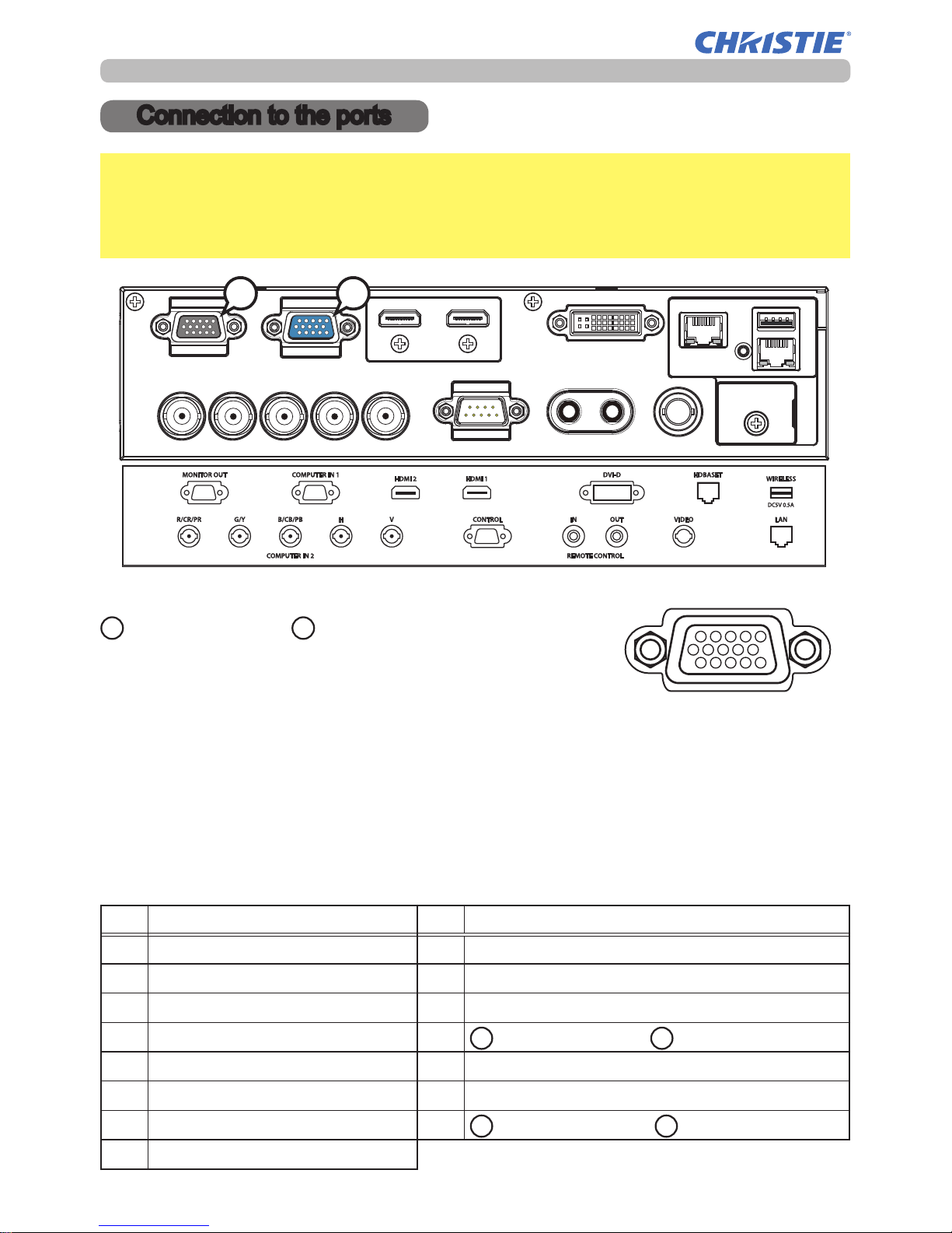
A
COMPUTER IN1, BMONITOR OUT
D-sub 15pin mini shrink jack
<Computer signal>
• Video signal: RGB separate, Analog, 0.7Vp-p, 75Ω terminated (positive)
• H/V. sync. signal: TTL level (positive/negative)
• Composite sync. signal: TTL level
<Component video signal>
• Video signal: Y with composite sync, Analog, 1.0±0.1Vp-p, 75Ω terminated
Cb/Pb, Analog, 0.7±0.1Vp-p, 75Ω terminated
Cr/Pr, Analog, 0.7±0.1Vp-p 75Ω terminated
• System: 480i@60, 480p@60, 576i@50, 720p@50/60, 1080i@50/60, 1080p@50/60
Pin Signal Pin Signal
1 Video Red, Cr/Pr 9 (No connection)
2 Video Green, Y 10 Ground
3 Video Blue, Cb/Pb 11 (No connection)
4 (No connection) 12
A
: SDA (DDC data)
B
: (No connection)
5 Ground 13 H. sync / Composite sync.
6 Ground Red, Ground Cr/Pr 14 V. sync.
7 Ground Green, Ground Y
15
A
: SCL (DDC clock)
B
: (No connection)
8 Ground Blue, Ground Cb/Pb
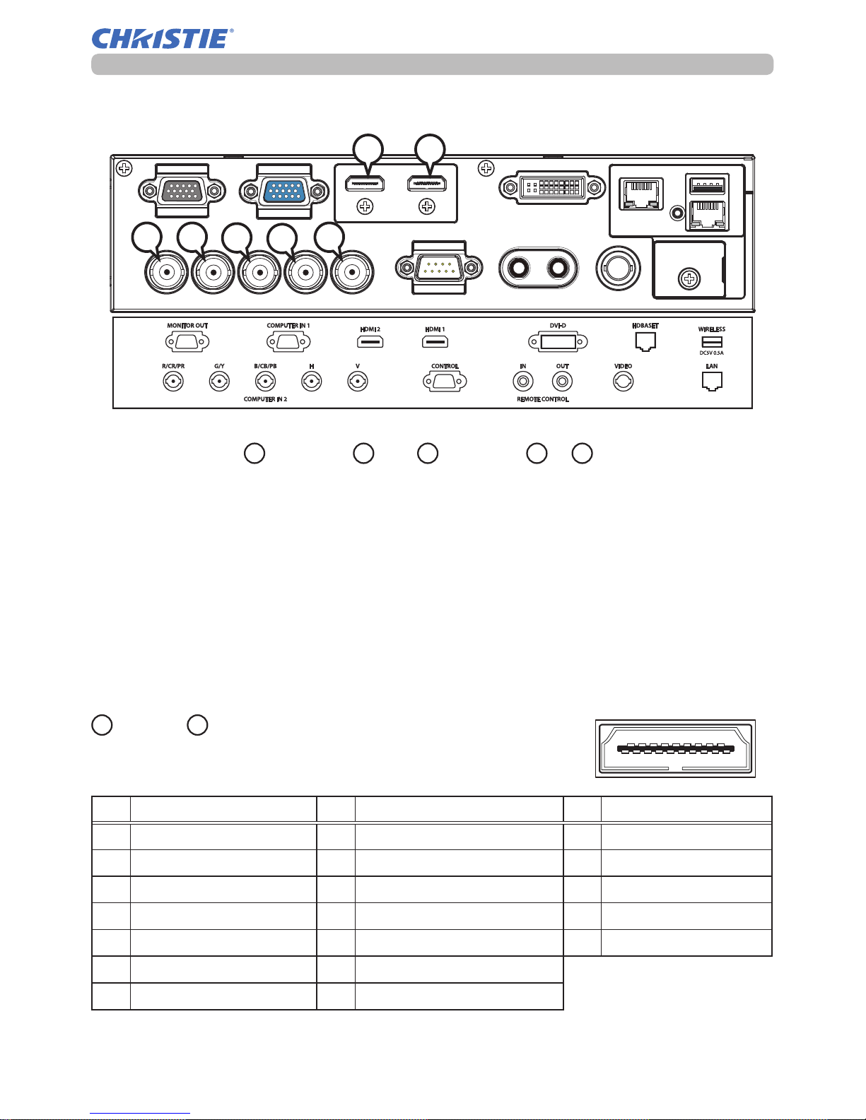
Connection to the ports
① ⑤④③②
⑥ ⑩⑨⑧⑦
⑪ ⑮⑭⑬⑫
①⑤ ④ ③ ②
⑥⑩ ⑨ ⑧ ⑦
⑪⑮ ⑭ ⑬ ⑫
Connection to the ports
NOTICE
►Use the cables with straight plugs, not L-shaped ones, as the
input ports of the projector are recessed.
►Only the signal that is input from the COMPUTER IN1 or IN2 can be output
from the MONITOR OUT port.
A
B
5
DWU951/DWX951/DXG1051 User's Manual - Technical 020-000664-01 Rev. 1 (01-2014)
Connection to the ports
H
HDMI 1, IHDMI 2
HDMITM connector
Pin Signal Pin Signal Pin Signal
1 T.M.D.S. Data2 + 8 T.M.D.S. Data0 Shield 15 SCL
2 T.M.D.S. Data2 Shield 9 T.M.D.S. Data0 - 16 SDA
3 T.M.D.S. Data2 - 10 T.M.D.S. Clock + 17 DDC/CEC Ground
4 T.M.D.S. Data1 + 11 T.M.D.S. Clock Shield
18
+5V Power
5 T.M.D.S. Data1 Shield 12 T.M.D.S. Clock -
19 Hot Plug Detect
6 T.M.D.S. Data1 - 13 CEC
7 T.M.D.S. Data0 + 14 Reserved (N.C. on device)
① ⑤④③
② ⑥ ⑩⑨⑧
⑦ ⑪ ⑮⑭⑬⑫⑲⑱⑰
⑯
①⑤④③
②⑥⑩⑨⑧
⑦⑪⑮⑭⑬
⑫
⑲⑱⑰
⑯
HI
C D
E
F
G
COMPUTER IN2 CR/CR/PR, DG/Y,
E
B/CB/PB, FH, GV
BNC jack x5
<Computer signal>
• Video signal: RGB separate, Analog, 0.7Vp-p, 75Ω terminated (positive)
• H/V. sync. signal: TTL level (positive/negative)
• Composite sync. signal: TTL level
<Component video signal>
• Video signal: Y with composite sync, Analog, 1.0±0.1Vp-p, 75Ω terminated
Cb/Pb, Analog, 0.7±0.1Vp-p, 75Ω terminated
Cr/Pr, Analog, 0.7±0.1Vp-p 75Ω terminated
• System: 480i@60, 480p@60, 576i@50, 720p@50/60, 1080i@50/60, 1080p@50/60
6
DWU951/DWX951/DXG1051 User's Manual - Technical 020-000664-01 Rev. 1 (01-2014)
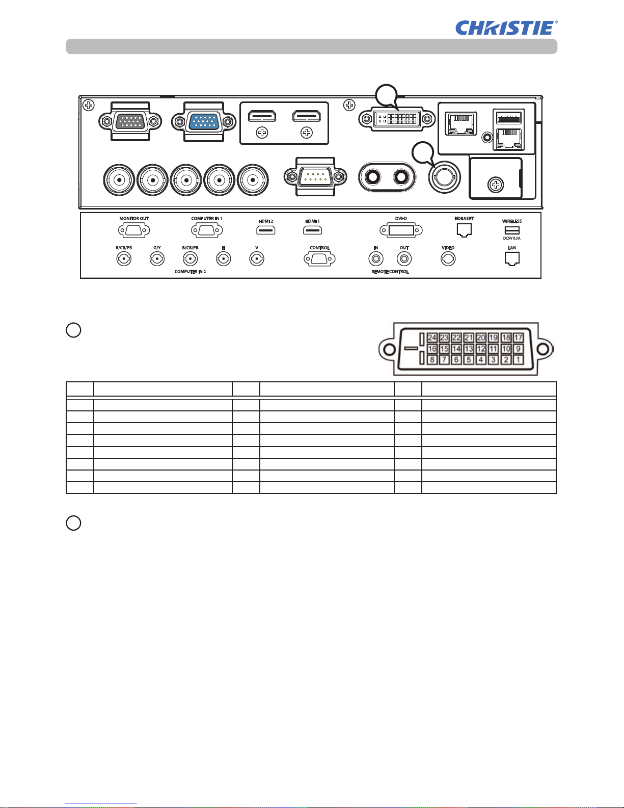
Connection to the ports
DVI-D
DVI-D jack (digital to digital)
Pin Signal Pin Signal Pin Signal
1 T.M.D.S. Data2 - 9 T.M.D.S. Data1 - 17 T.M.D.S. Data0 2 T.M.D.S. Data2 + 10 T.M.D.S. Data1 +
18
T.M.D.S. Data0 +
3 T.M.D.S. Data2/4 Shield 11 T.M.D.S. Data1/3 Shield 19 T.M.D.S. Data0/5 Shield
4 - 12 -
20
5 - 13 - 21 6 DDC Clock 14 +5V Power 22 T.M.D.S. Clock Shield
7 DDC Data 15 Ground (for +5V) 23 T.M.D.S. Clock +
8 - 16 Hot Plug Detect 24 T.M.D.S. Clock -
J
VIDEO
BNC jack
• Composite video signal, Analog, 1.0±0.1Vp-p, 75Ω terminator
• System: NTSC, PAL, SECAM, PAL-M, PAL-N, NTSC4.43, PAL(60Hz)
K
J
K
7
DWU951/DWX951/DXG1051 User's Manual - Technical 020-000664-01 Rev. 1 (01-2014)
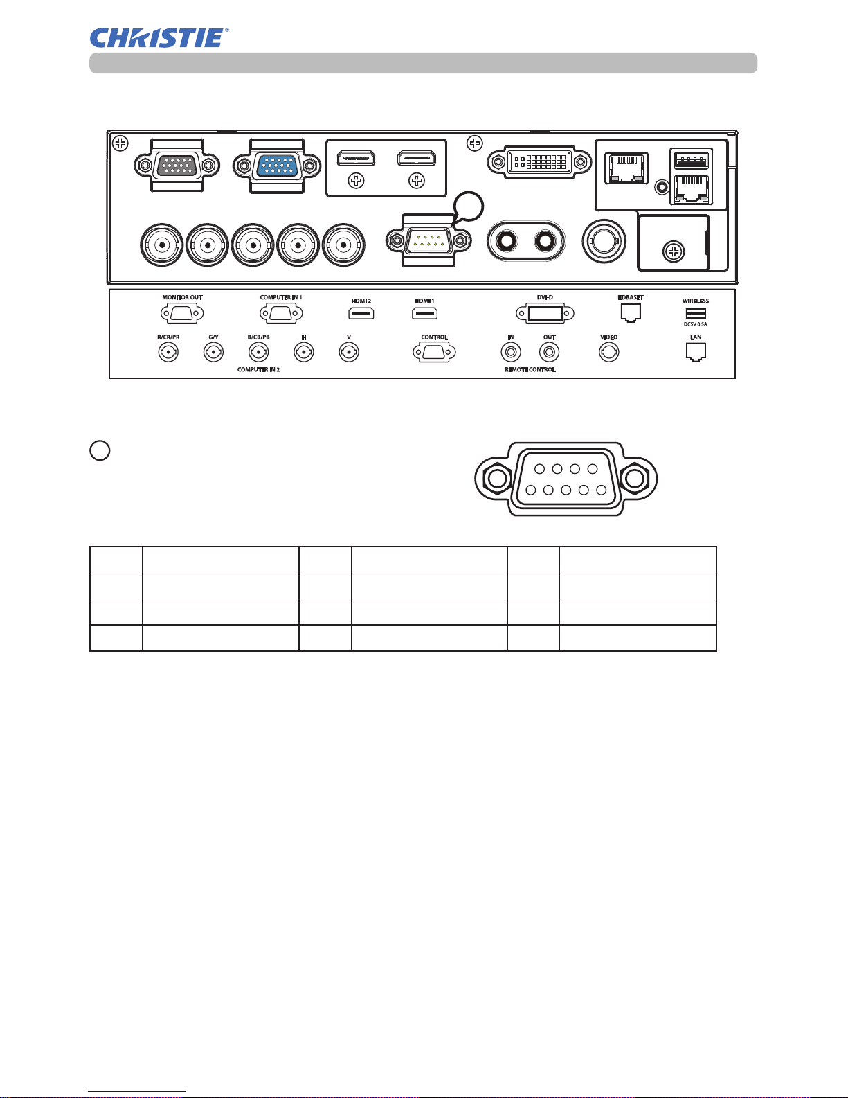
Connection to the ports
L
CONTROL
D-sub 9pin plug
* About the details of RS-232C communication,
please refer to the next section.
Pin Signal Pin Signal Pin Signal
1 (No connection) 4 (No connection) 7 RTS
2 RD 5 Ground 8 CTS
3 TD 6 (No connection) 9 (No connection)
①②
⑥⑦⑧⑨
⑤ ④ ③
L

8
DWU951/DWX951/DXG1051 User's Manual - Technical 020-000664-01 Rev. 1 (01-2014)
Connection to the ports
M
HDBASET
RJ-45 jack
Pin Signal Pin Signal Pin Signal
1 HDBaseT0+ 4 HDBaseT2+ 7 HDBaseT3+
2 HDBaseT0- 5 HDBaseT2-
8 HDBaseT3-
3 HDBaseT1+ 6 HDBaseT1-
① ⑤④③
② ⑥ ⑧
⑦
①⑤④③
②⑥⑧
⑦
N
LAN
RJ-45 jack
Pin Signal Pin Signal Pin Signal
1 TX+ 4 - 7 2 TX- 5 -
8 -
3 RX+ 6 RX-
① ⑤④③
② ⑥ ⑧
⑦
①⑤④③
②⑥⑧
⑦
M
N
9
DWU951/DWX951/DXG1051 User's Manual - Technical 020-000664-01 Rev. 1 (01-2014)
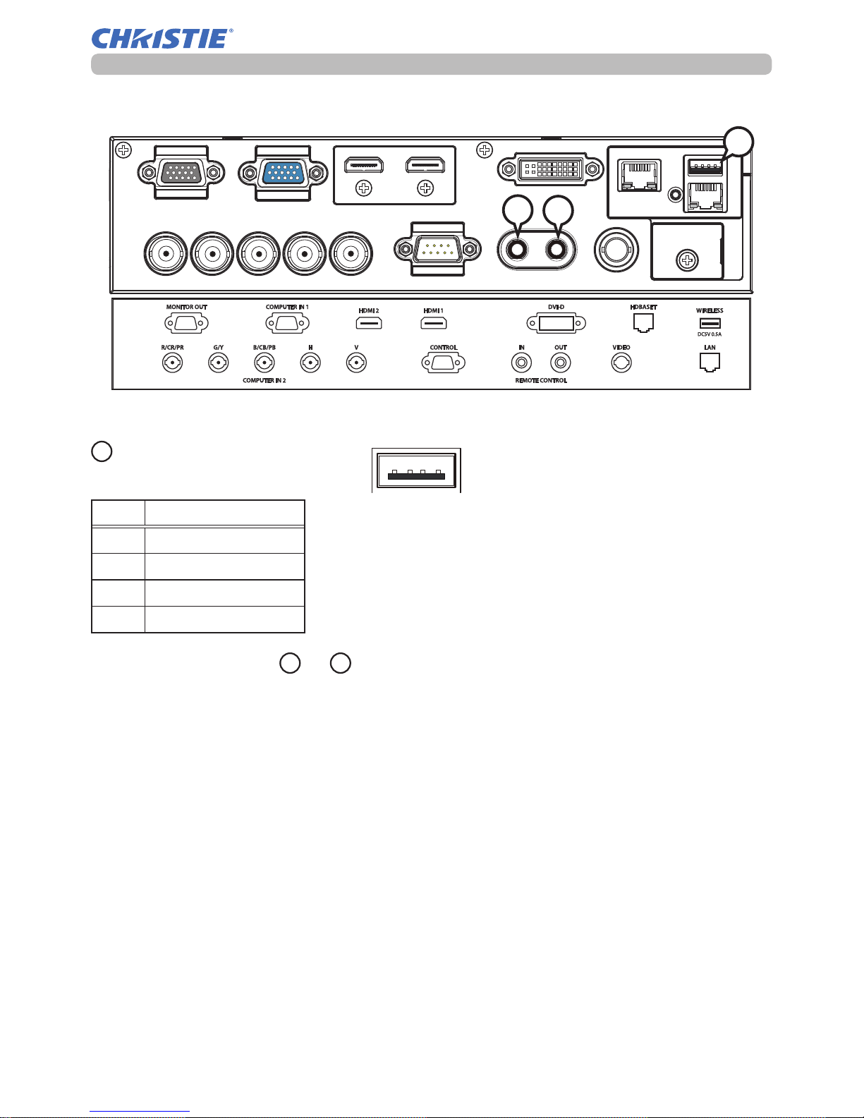
Connection to the ports
REMOTE CONTROL PIN, QOUT
Ø3.5 stereo mini jack
O
WIRELESS PORT
Only for USB wireless adapter.
Pin Signal
1 +5V
2 - Data
3 + Data
4 Ground
① ④③②
①④ ③ ②
Q
P
O
10
DWU951/DWX951/DXG1051 User's Manual - Technical 020-000664-01 Rev. 1 (01-2014)
RS-232C cable
(cross)
RS-232C
CONTROL
①②
⑥⑦⑧⑨
⑤ ④ ③
CD (1) (1)
-
RD(2) (2) RD
TD (3) (3) TD
DTR (4) (4)
-
GND (5) (5) GND
DSR (6) (6)
-
RTS (7) (7) RTS
DTS (8) (8) CTS
RI (9) (9)
-
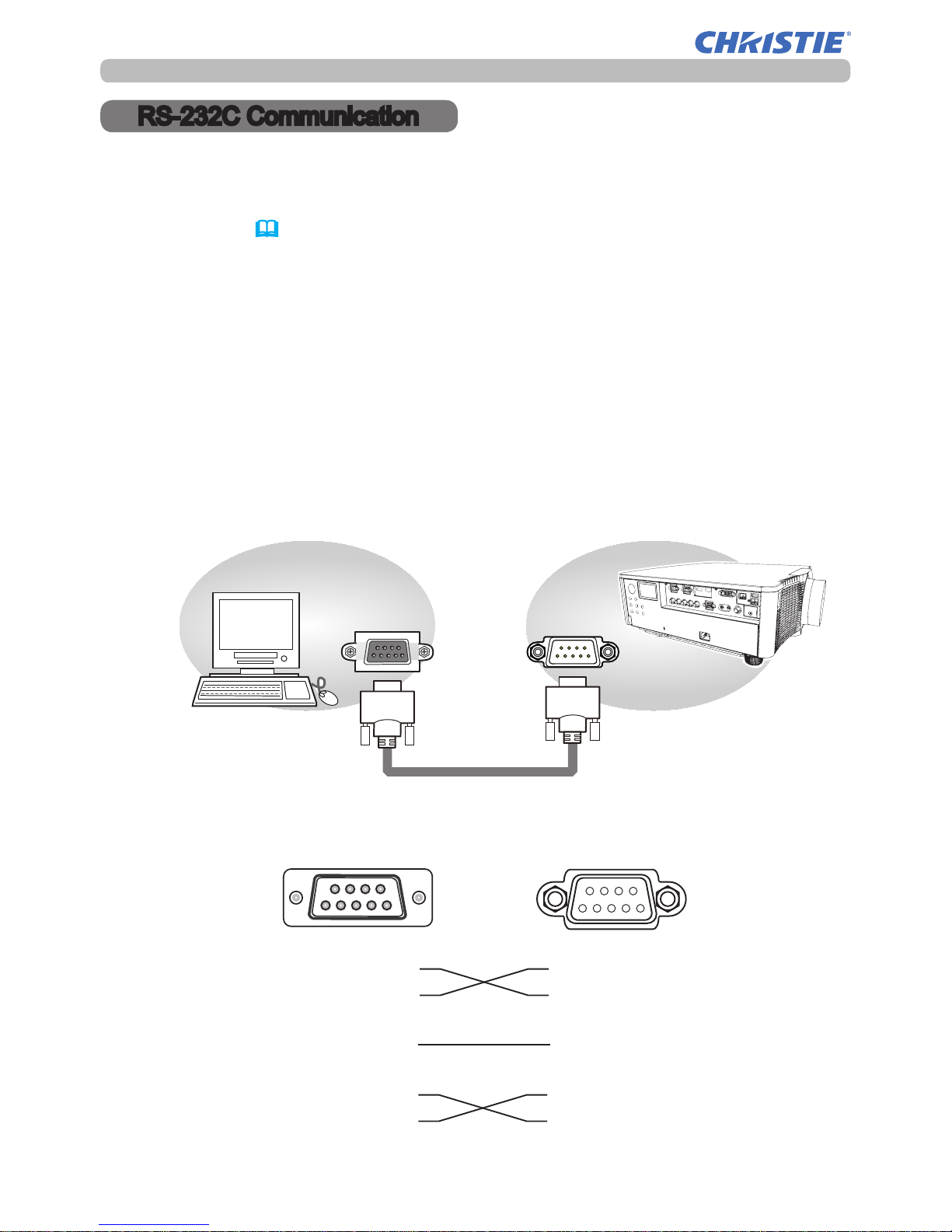
RS-232C Communication
RS-232C Communication
When the projector connects to the computer by RS-232C communication, the
projector can be controlled with RS-232C commands from the computer.
For details of RS-232C commands, refer to RS-232C Communication / Network
command table (
&19).
Connection
1.
Turn off the projector and the computer.
2.
Connect the projector's CONTROL port and the computer's RS-232C port
with a RS-232C cable (cross). Use the cable that ful lls the speci cation
shown in gure.
3.
Turn the computer on, and turn the projector on after the computer has started up.
4.
Set the COMMUNICATION TYPE to OFF in the COMMUNICATION menu of the
OPTION - SERVICE menu.
1
9876
5432
CONTROL port
of the projector
RS-232C port
of the computer
11
DWU951/DWX951/DXG1051 User's Manual - Technical 020-000664-01 Rev. 1 (01-2014)
RS-232C Communication
Communication settings
1. Protocol
19200bps, 8N1
2. Command format
("h" shows hexadecimal)
Byte Number
0 1 2 3 4 5 6
7 8 9 10 11 12
Command
Action
Header Data
Header
code
Packet
Data
size
CRC
ag
Action Type
Setting
code
L H L H L H L H L H L H
<SET>
Change setting to
desired value [(cL)(cH)]
by [(bL)(bH)].
BEh EFh 03h 06h 00h
(aL) (aH) 01h 00h (bL) (bH) (cL) (cH)
<GET>
Read projector
internal setup value [(bL)
(bH)] .
(aL) (aH) 02h 00h (bL) (bH) 00h 00h
<INCREMENT>
Increment setup value
[(bL)(bH)] by 1.
(aL) (aH) 04h 00h (bL) (bH) 00h 00h
<DECREMENT>
Decrement setup value
[(bL)(bH)] by 1.
(aL) (aH) 05h 00h (bL) (bH) 00h 00h
<EXECUTE> Run a
command [(bL)(bH)].
(aL) (aH) 06h 00h (bL) (bH) 00h 00h
[Header code] [Packet] [Data size]
Set [BEh, EFh, 03h, 06h, 00h] to byte number 0 to 4.
[CRC ag]
For byte number 5 and 6, refer to
RS-232C Communication / Network
command table
(&19).
[Action]
Set functional code to byte number 7 and 8.
<SET> = [01h, 00h], <GET> = [02h, 00h], <INCREMENT> = [04h, 00h]
<DECREMENT> = [05h, 00h], <EXECUTE> = [06h, 00h]
Refer to the Communication command table (
&above).
[Type] [Setting code]
For byte number 9 to 12, refer to RS-232C Communication / Network
command table (
&19).

12
DWU951/DWX951/DXG1051 User's Manual - Technical 020-000664-01 Rev. 1 (01-2014)
RS-232C Communication
3. Response code / Error code
("h" shows hexadecimal)
(1) ACK reply: 06h
When the projector receives the Set, Increment, Decrement or Execute
command correctly, the projector changes the setting data for the specied
item by [Type], and it returns the code.
(2) NAK reply: 15h
When the projector cannot understand the received command, the projector
returns the error code.
In such a case, check the sending code and send the same command again.
(3) Error reply: 1Ch + 0000h
When the projector cannot execute the received command for any reasons,
the projector returns the error code.
In such a case, check the sending code and the setting status of the projector.
(4) Data reply: 1Dh + xxxxh
When the projector receives the GET command correctly, the projector returns
the response code and 2 bytes of data.
NOTE • For connecting the projector to your devices, please read the
manual for each devices, and connect them correctly with suitable cables.
• Operation cannot be guaranteed when the projector receives an undened
command or data.
• Provide an interval of at least 40ms between the response code and any
other code.
• The projector outputs test data when the power supply is switched ON, and
when the lamp is lit. Ignore this data.
• Commands are not accepted during warm-up.
• When the data length is greater than indicated by the data length code, the
projector ignores the excess data code. Conversely when the data length is
shorter than indicated by the data length code, the projector returns the error
code to the computer.
 Loading...