

Christie DS4K, DS8K, MIRAGE S4K, DLV1400-DX, MIRAGE S8K User Manual
...
1 INTRODUCTION
2 INSTALLATION &
SETUP
3 OPERATION
4 MAINTENANCE
5 TROUBLESHOOTING
6 SPECIFICATIONS
APPENDICES
NOTE: Due to continuing research, all information in this manual is subject to change without notice.
013-100015 (02/05)
Software v1.0 User’s Manual
User’s Manual
Table of Contents
1.1 Projector Overview......................................................................................... 1-1
1.2 Components.....................................................................................................1-2
1.3 Purchase Record and Servicing.......................................................................1-2
2.1 Quick Setup..................................................................................................... 2-1
2.2 Installation Considerations.............................................................................. 2-3
2.3 Connecting Sources....................................................................................... 2-12
2.4 Connecting Communications........................................................................ 2-15
2.5 System Integration – GPIO Connector.......................................................... 2-17
2.6 Power Connection.........................................................................................2-17
3.1 About the Projector ....................................................................................... 3-1
3.2 Using the Remote or Built-in Keypad............................................................. 3-3
3.3 Navigating the Menus...................................................................................3-10
3.4 Using Inputs and Channels............................................................................3-14
3.5 Adjusting the Image...................................................................................... 3-19
3.6 Adjusting System Parameters and Advanced Controls................................. 3-34
3.7 Working with the Lamp ...............................................................................3-44
3.8 Status Menu ................................................................................................. 3-47
3.9 3D Images (Mirage Only)............................................................................. 3-48
3.10 Using Multiple Projectors............................................................................. 3-57
3.11 Remote Control of the Projector .................................................................. 3-66
3.12 Error Conditions............................................................................................ 3-67
4.1 Warnings and Safety Guidelines..................................................................... 4-1
4.2 Cleaning and Maintenance Guide................................................................... 4-4
4.3 Replacing Remote Batteries............................................................................ 4-5
4.4 Lamp and Filter Replacement......................................................................... 4-5
4.5 Replacing the Projection Lens......................................................................... 4-9
5.1 Displays........................................................................................................... 5-1
5.2 Lamp .............................................................................................................. 5-3
5.3 Ethernet...........................................................................................................5-3
6.1 Specifications.................................................................................................. 6-1
Appendix A: Glossary...............................................................................................A-1
Appendix B: Keypad Reference.................................................................................B-1
Appendix C: Serial Communications.........................................................................C-1
Appendix D: Throw Distance.................................................................................... D-1
Appendix E: System Integration ................................................................................E-1
Appendix F: Optional Input Modules.........................................................................F-1

Section 1
Introduction
1.1 Projector
Overview
Christie DS+4K/8K and Mirage S+2K/4K/8K are professional 3-chip projectors based
on next-generation Digital Light
Processing (DLP) technology by Texas
Instruments. These projectors are
compatible with standard international
video formats and can interface with IBM
compatible PC, Macintosh
workstations. All models deliver highbrightness, high-resolution, and high-quality
images. Christie DS+4K/8K, projectors are
an ideal choice in boardrooms, recreation
facilities and auditoriums.
Mirage S+2K/4K/8K projectors provide a
powerful combination of SXGA+
resolution, high brightness and high contrast ratios to produce flawless, realistic threedimensional graphic images for simulation, virtual reality and other stereographic
related applications.
The DLV1400-DX is designed for the demands of 24/7 control room applications and
provides long term reliability and performance.
Key Features:
• Native SXGA+ resolution (1400 x 1050, fully scaleable)
• Internal scaling of stereo signals (Mirage models)
• 10-bit video processing
• Built-in multi-standard video decoder
• Display of NTSC, PAL and SECAM video input
• User replaceable Cermax
• LiteLOC
• Motorized lens mount for all models except DLV1400-DX
• Auto-setup feature
• Integrated ChristieNET
• Networking ability through RS232 and RS422 connectors
• Status LED display on built-in keypad for easy projector status monitoring
• Control with IR, wired or built-in keypad
Refer to Section 6 for a complete list of Specifications including Brightness and
Contrast.
for constant brightness
computers and
Xenon lamp
-
User’s Manual 1-1

Section 1: Introduction
Dealer:
Dealer Phone Number:
Projector Serial Number:
Purchase Date:
Installation Date, i
f applicable:
proj
How the
ector works '
1.2 Components
1.3 Purchase
Record and
Servicing
The projector accepts data/graphics and video input signals for projection onto front
or rear flat screens. High brightness light is generated by an internal Xenon lamp then
modulated by three DMD (digital micromirror device) panels that provide digitized
red, green or blue color information. Light from the “on” pixels of each panel is
reflected, converged and then projected to the screen through a single front lens,
where all pixels are perfectly superimposed as a sharp full-color image (2D or 3D for
Mirage models only).
The following listed items are shipped with your projector. Ensure you have received
all these items before using your projector.
• User’s Manual
• IR remote keypad (includes two, 1.5V AA batteries and a mini-stereo cable for
conversion to wired)
• Line cord
• Stereo 3D Cable
• Warranty Card
Whether the projector is under warranty or the warranty has expired, Christie’s highly
trained and extensive factory and dealer service network is always available to quickly
diagnose and correct projector malfunctions. Service manuals and updates are
available to service technicians for all projectors.
If you encounter any problems with the projector and require assistance, contact your
dealer or Christie Digital Systems. Fill out the information in the table below and keep
with your records for future reference.
Purchase Record
NOTE: The serial number can be found on the license label, which is located at the back of the projector.
You can also register your product on-line by visiting www.christiedigital.com ⇒
Service and Support ⇒ Product Registration. This will keep you in touch with all
the latest product information, such as updates, technical bulletins, downloads and
Christie newsletters.
1-2
User’s Manual

2.1 Quick Setup
Section 2
Installation & Setup
The instructions provided here are for those that are familiar with the projector and
wish to quickly set it up and use it temporarily. Refer to the remaining subsections of
this manual for a more complete setup.
Step 1 '
Step 2 '
Install a Projection Lens
The projection lens is shipped separately from the projector and must be installed
prior to setting up the projector. Install the projection lens as described in 4.5
Replacing the Projection Lens.
Remove the lens plug from the lens opening in the projector before installing the
lens.
Remove the lens when shipping the projector and reuse the lens plug to prevent
dust and debris from entering and settling on the projector’s optical components.
Position the Projector
Place the projector on a sturdy, level surface and position it so that it is perpendicular
to the screen at a suitable distance. In general, the further back the projector is
positioned from the screen, the larger the image will be.
If required, you can level the projector by adjusting its three feet. With the projector
positioned perpendicular to the screen the image will appear rectangular instead of
keystoned.
For more detailed instructions on positioning the projector refer to Projector Position
and Mounting later in this section.
Step 3 '
Connect a Source
Located at the back of the projector is the input panel where all source connections are
made. Each input is clearly labeled for easy identification.
Using the appropriate cable(s), connect your source. Connect RGB and YPbPr sources
INPUT 1 located in the upper right corner of the input panel. Use the DVI-I
to
connector at
video to
modules can be installed at
Refer to 2.3 Connecting Sources for more details on connecting a specific source.
INPUT 2 to connect analog or digital display signals. Connect composite
INPUT 3 and S-video to INPUT 4. NOTE: One of the available optional input
INPUT 5 or INPUT 6 for additional connections.
User’s Manual 2-1

Section 2: Installation and Setup
p
Ste
4 '
Step 5 '
Step 6 '
Connect the Line Cord
The North American rated line cord is provided with each projector.
Plug the line cord to the AC receptacle located on the right hand side of the projector
and the 3-pronged end into a grounded AC outlet. The input voltage to the projector
must be capable of 100 – 240 VAC in 500W and 1000W models and 200-240VAC in
1200W models. (See also Section 6 – Specifications for complete details on all power
requirements.)
Use the approved North American-rated line cord supplied with the projector. If you
are connecting to an area outside of North America make sure you are using an
appropriately rated line cord.
Turn the Projector ON
Press the
POWER button on either the remote or built-in keypad to turn the
projector on. Wait a few minutes to allow the projector to warm up. The LED status
window displays an active pattern of segments to indicate the projector is changing its
state from powered down to powered up. The message “On” appears in the display
when the projector has completed its initialization and is ready for use.
Select a Source
Press one of the input keys on the remote or built-in keypad to select and display the
image for the source you connected in Step 3.
Step 7 '
Adjust Image
Adjust the more common image settings, such as Brightness, Contrast, Gamma,
Focus, Zoom etc. using the direct keys on the IR remote.
You can also access the menu system and adjust these and other image settings by
Menu
pressing
on the remote.
2-2
User’s Manual
'
2.2 Installation
Considerations
Proper installation of your projector will ensure the quality of your display. Whether
you are installing a projector temporarily or permanently you should take the
following into account to ensure your projector performs optimally.
Section 2: Installation and Setup
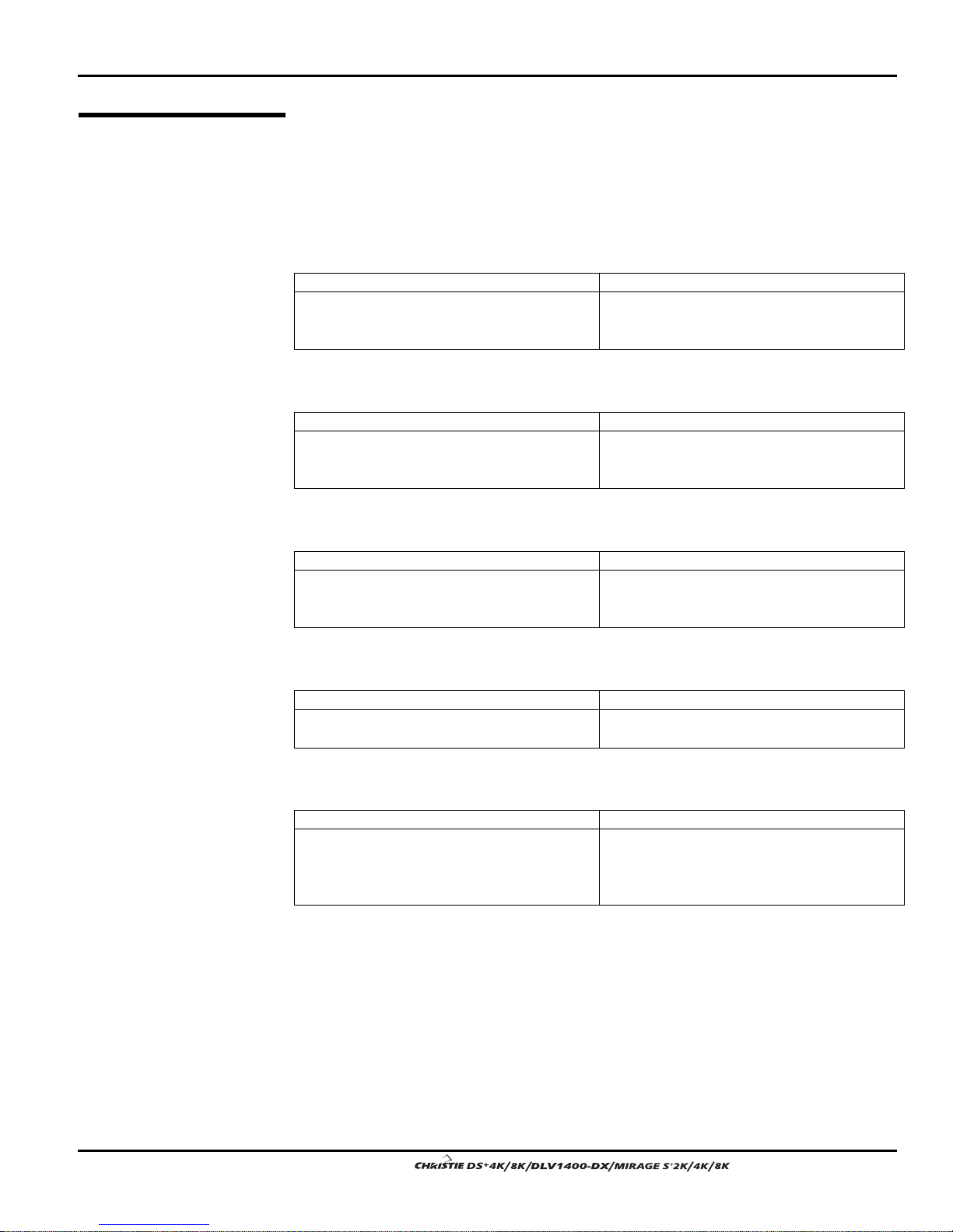
Installation type '
Choose the installation type that best suits your needs: front or rear screen, floor
mount or inverted mount.
Front Screen, Floor Mount Installation
ADVANTAGES CONSIDERATIONS
• Easy to set up
• Can be moved or changed quickly
• Easy to access
• Shares floor space with audience
Front Screen, Inverted Mount (ceiling) Installation
ADVANTAGES CONSIDERATIONS
• Does not take up audience space
• Projector is unobtrusive
• Projector cannot be accidentally moved
• Installation is more permanent
• It is more difficult to access the projector
Rear Screen, Floor Mount Installation
ADVANTAGES CONSIDERATIONS
• Projector is completely hidden
• Projector is easily accessed
• Usually good ambient light rejection
• Requires separate room
• Installatio n cost is usuall y higher
Screen Type
Rear Screen, Inverted Mount (ceiling) Installation
ADVANTAGES CONSIDERATIONS
• Projector is completely hidden
• Usually good ambient light rejection
• Requires separate room
• Installatio n cost is usuall y higher
Rear Screen, Floor Mount with Mirror
ADVANTAGES CONSIDERATIONS
• Projector is completely hidden
• Usually good ambient light rejection
• Requires less space behind screen than
other rear screen installations
• Requires separate room
• Installatio n cost is usuall y higher
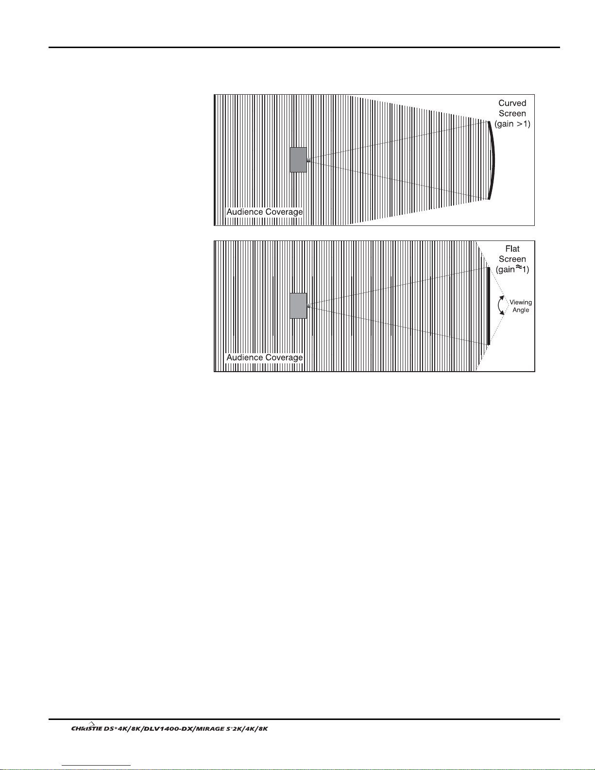
Front Screen Installations
In front screen installations the projector and audience are positioned in front of the
screen, which can be flat or curved.
Flat screens are most recommended with this projector. They offer a gain of about 1
with a viewing angle just less than 180°. This type of screen reflects incident light
equally in all directions so the audience can see the display from various angles.
Curved screens have a gain greater than 1 with a viewing angle much less than 180°.
This type of screen does not reflect incident light equally in all directions instead it is
User’s Manual 2-3.
Section 2: Installation and Setup
concentrated in a viewing cone. The audience sitting within the viewing cone area will
see a brighter image than those sitting just outside this area.
Rear screen installations
There are two basic types of rear screens: diffused and optical.
A diffused screen has a surface, which spreads the light striking it. Purely diffused
screens have a gain of less than 1. The main advantage of the diffused screen is its
wide viewing angle, similar to that of a flat screen for front screen projection. This
type of screen is suitable when a wide viewing angle is required but there is low
ambient room lighting.
Optical screens take light from the projector and redirect it to increase the light
intensity at the front of the screen. This reduces it in other areas. A viewing cone,
similar to that of a curved front screen installation is created. This type of screen is
better suited for brightly lit rooms where the audience is situated within the viewing
cone.
Screen size
Choose a screen size, which is appropriate for your lens and application. Keep in mind
that if the projector will be used to display text information, the image size must allow
the audience to recognize all text clearly. The eye usually sees a letter clearly if eyeto-text distance is less than 150 times the height of the letter. Small text located too far
from the eye will likely be illegible at a distance no matter how sharply and clearly it
is displayed.
To fill a screen with an image, the aspect ratio of the screen should be equal to the
aspect ratio of the image (expressed as the ratio of its width to its height). Standard
video from a VCR has a 4:3 or 1.33:1 aspect ratio. For example, to display a VCR
2-4
User’s Manual

Section 2: Installation and Setup
A
output with a 4:3 aspect ratio onto a 10-foot (3m) high screen, the width of the screen
must be at least 13.3feet (4m).
mbient Lighting '
Other Considerations '
Projector Position and
Mounting '
The high brightness of this projector is well suited for locations where ambient
lighting might be considered less than ideal for projection. A typical room with ceiling
lights and windows rarely requires special attention. Contrast ratio in your images will
be noticeably reduced only if light directly strikes the screen, such as when a shaft of
light from a window or floodlight falls on the image. Images may then appear washed
out and less vibrant.
In general, avoid or eliminate light sources directed at the screen.
Other considerations and tips that can help improve your installation:
• Keep the ambient temperature constant and below 35°C (95°F). Keep the
projector away from heating and/or air conditioning vents. Changes in
temperature may cause drifts in the projector circuitry, which may affect
performance.
• Keep the projector away from devices, which radiate electromagnetic energy
such as motors and transformers. Common sources of these include slide
projectors, speakers, power amplifiers, elevators, etc.
Choose the best screen size for the application. Since more magnification reduces
brightness, use a screen size appropriate for the venue but not larger than required.
Installing a large screen in a small room is similar to watching television at a close
range; too large a screen can overpower a room and interfere with the overall effect. A
good rule of thumb is to be no closer than 1.5 times the width of the screen.
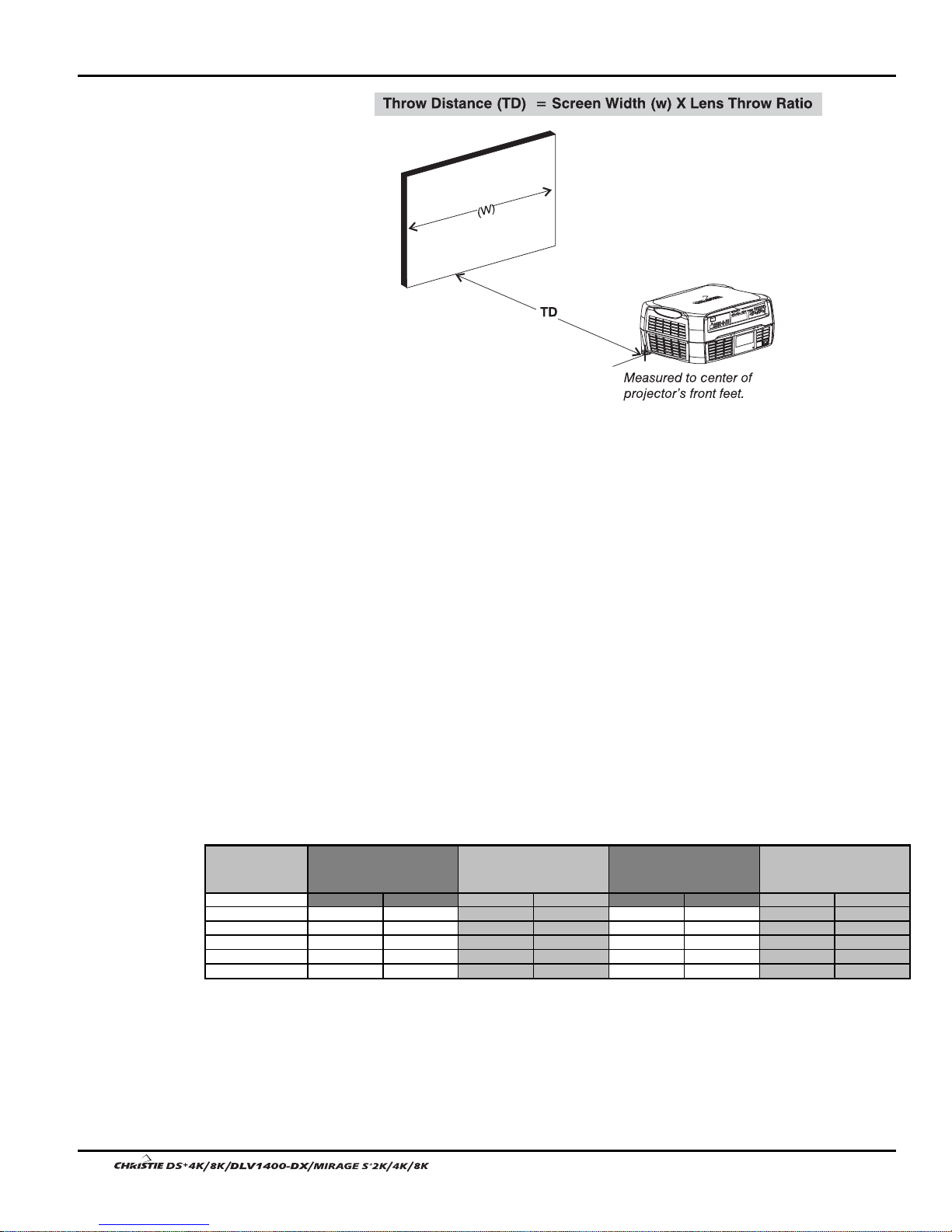
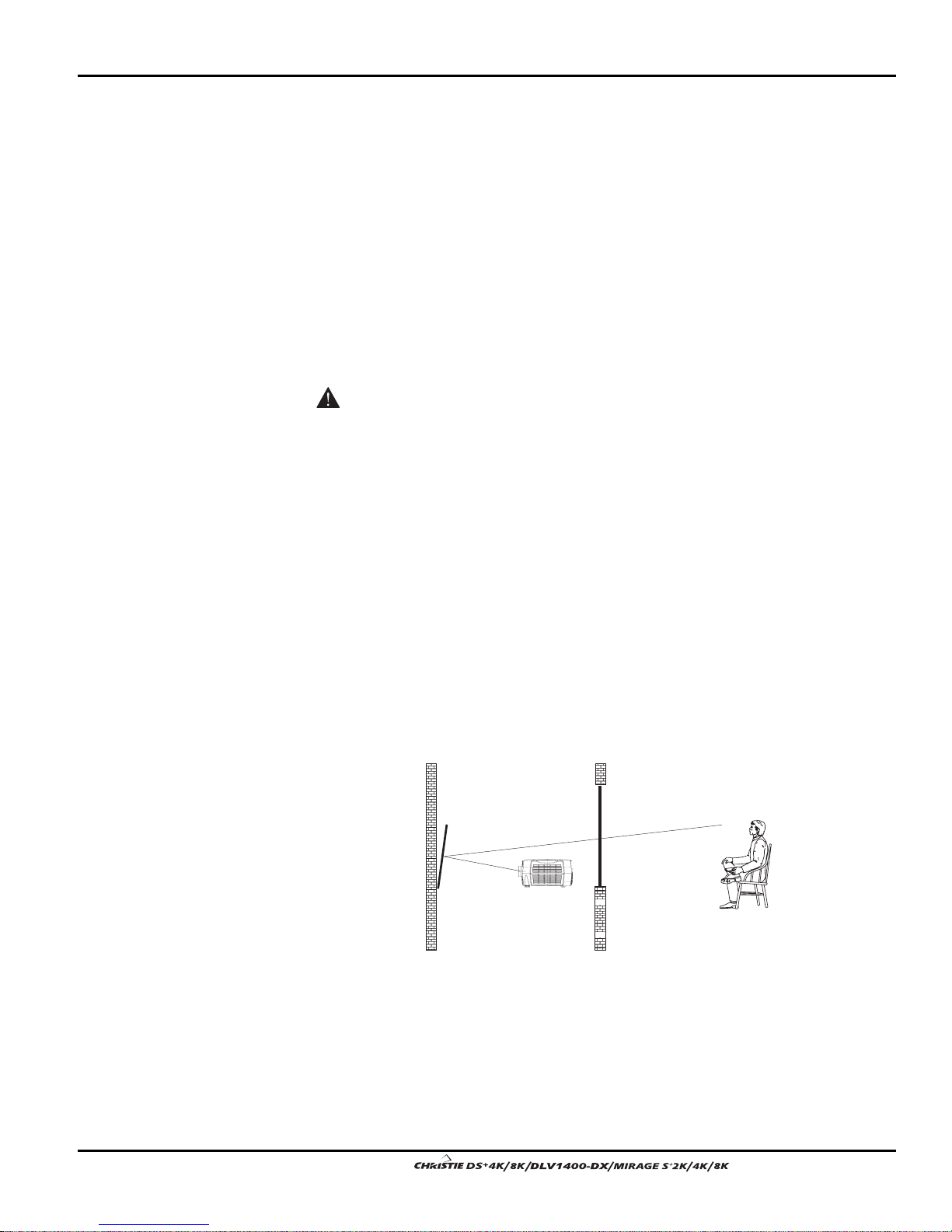
Throw distance
Throw distance is the distance measured from your projector’s front feet to the screen.
This is an important calculation in any project or ins ta llati on as it determines whether
or not you have enough room to install your projector with a desired screen size and if
your image will be of the right size for your screen.
You can quickly estimate the throw distance by taking the horizontal width of the
screen and multiplying it by the lens throw ratio. The result of this calculation tells
you roughly how far back the projector should be positioned from the screen in order
to project a focused image large enough to fill the screen. For example, using a 0.73:1
lens, throw distance would roughly be 0.73 x screen width.
IMPORTANT: Once you determine the type of lens and screen size you’re going
to use, calculate the precise throw distance using the formula or graphs located
in Appendix D. Due to lens manufacturing tolerances for lens focal length, actual
throw distance can vary
ratio.
±
5% between lenses described as having the same throw
User’s Manual 2-5.
Section 2: Installation and Setup
Figure 2.1. Estimating Throw Distance
Vertical and horizontal position
The correct vertical and horizontal position of the projector in relation to the screen
depends on the lens type and the screen size. Ideally, the projector should be
positioned perpendicular to the screen. This way, the image will appear rectangular
instead of keystoned (trapezoidal).
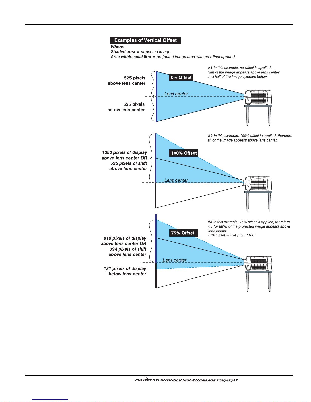
The vertical position of the image can be offset – that is moved above or below the
optical axis (lens center) by adjusting the fully motorized lens mount with the keypad.
The amount of vertical offset available depends directly on the lens installed in the
projector and can be slightly limited if horizontal offset has been applied. Vertical
offset can also be expressed as the percent of half the image height OR the number of
pixels of shift from lens center. Refer to Figure 2.2 for some illustrated examples of
vertical offset.
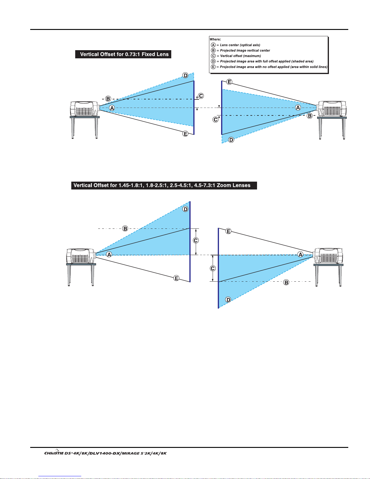
Table 2.1 along with Figure 2.3 show the maximum vertical offset of a lens or
alternatively, how much of your projected image will appear above or below lens
center if the maximum vertical offset is applied using that lens.
Table 2.1. Lens Offsets
Lens Type Vertical Offset
(% of Half Height)
%Pixels%Pixels%Pixels%Pixels
0.73:1 fixed 37% +/-196 69% +/-721 22% +/-153 61% +/-853
1.45-1.8:1 zoom 100% +/-525 100% +/-1050 50% +/-350 75% +/-1050
1.8-2.5:1 zoom 100% +/-525 100% +/-1050 50% +/-350 75% +/-1050
2.5-4.5:1 zoom 100% +/-525 100% +/-1050 50% +/-350 75% +/-1050
4.5-7.3:1 zoom 100% +/-525 100% +/-1050 50% +/-350 75% +/-1050
Maximum amount of
projected image above or
below lens center
Horizontal Offset
(% of Half Width)
Maximum amount of
projected image to one side
of lens center
% Offset = # pixels of offset / half panel resolution x 100.
2-6
User’s Manual
Section 2: Installation and Setup
Figure 2.2. Vertical Offset Examples
User’s Manual 2-7.
Section 2: Installation and Setup
2-8
Figure 2.3. Lens Vertical Offsets
User’s Manual
Section 2: Installation and Setup
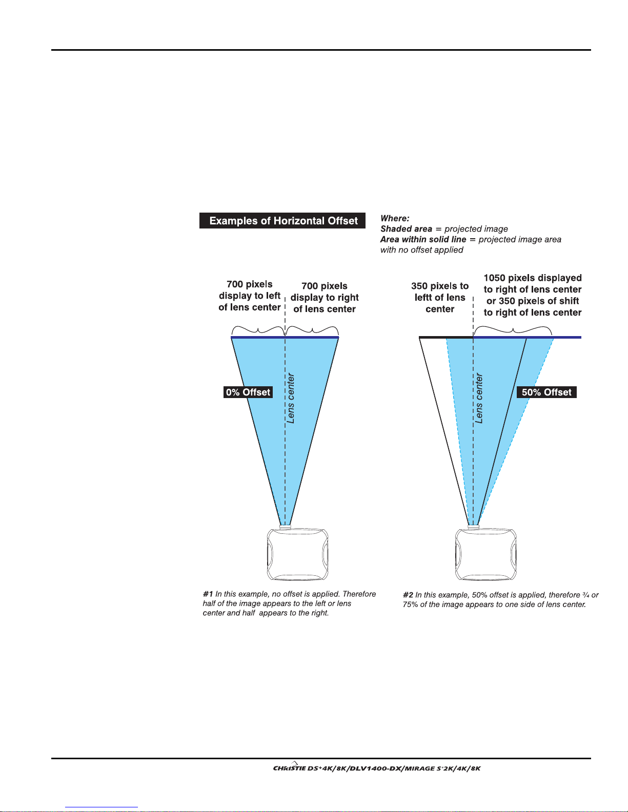
The horizontal position of the image can be offset – that is moved to the left or right
of lens center, by adjusting the fully motorized lens mount through software. The
amount of horizontal offset available depends on the lens installed and if the image
has already been vertically offset. Horizontal offset can also be expressed as the
percent of half the image width – the number of pixels of shift to one side of lens
center. Refer to Figure 2.4 for some illustrated examples of horizontal offset.
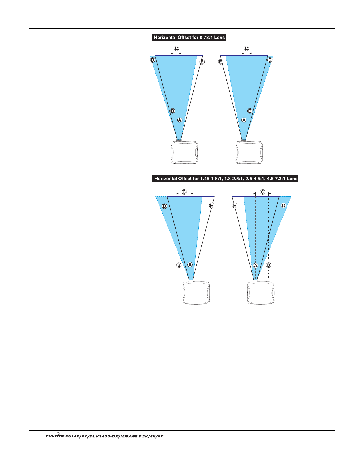
See also Table 2.1 along with Figure 2.5 which shows the maximum horizontal offset
of a lens or alternatively, how much of your projected image will appear to one side of
lens center if the maximum horizontal offset is applied using that lens.
Figure 2.4. Horizontal Offset Examples
User’s Manual 2-9.
Section 2: Installation and Setup
2-10
Figure 2.5. Lens Horizontal Offsets
User’s Manual
Section 2: Installation and Setup
Mounting
There are several methods for mounting the projector. Depending on your chosen
installation, one method may be more suitable than another. In typical front and rear
screen installations the projector can be mounted to a secure and level surface, such as
a table or cart. Carts are useful when the projector has to be moved during a
presentation or from site to site. It is recommended you lock the wheels on a cart,
when it’s in position, to prevent someone from accidentally moving it during a
presentation.
CEILING MOUNT - The projector can also be inverted and suspended from the ceiling
using a specially designed ceiling mount fixture. This type of mounting is
recommended for fixed installations and for those that want the projector out of plain
view or have a limited amount of space for projector and audience. (Available 2005)
Use only the CHRISTIE approved ceiling mount kit designed for
your projector.
SPECIAL MOUNTING – The projector can be rotated (front-to-back) up to 360 degrees
and mounted without it affecting performance. However, the side-to-side tilt limit of
the projector must not exceed ±15 degrees. This tilt limit is required to ensure optimal
performance of the projector.
Adjusting projector height
You can modify the height of the projector to remedy a slightly unlevel mounting
surface by adjusting the two feet threaded into the bottom chassis. Turn each foot
clock-wise or counter-clockwise until the project is level on all sides.
Folded Optics
In rear screen applications where space behind the projector is limited, a mirror may
be used to fold the optical path. See Figure 2.6. The position of the projector and
mirror must be accurately set – if considering this type of installation call your dealer
for assistance.
Figure 2.6.
User’s Manual 2-11.
Section 2: Installation and Setup
2.3 Connecting
Sources
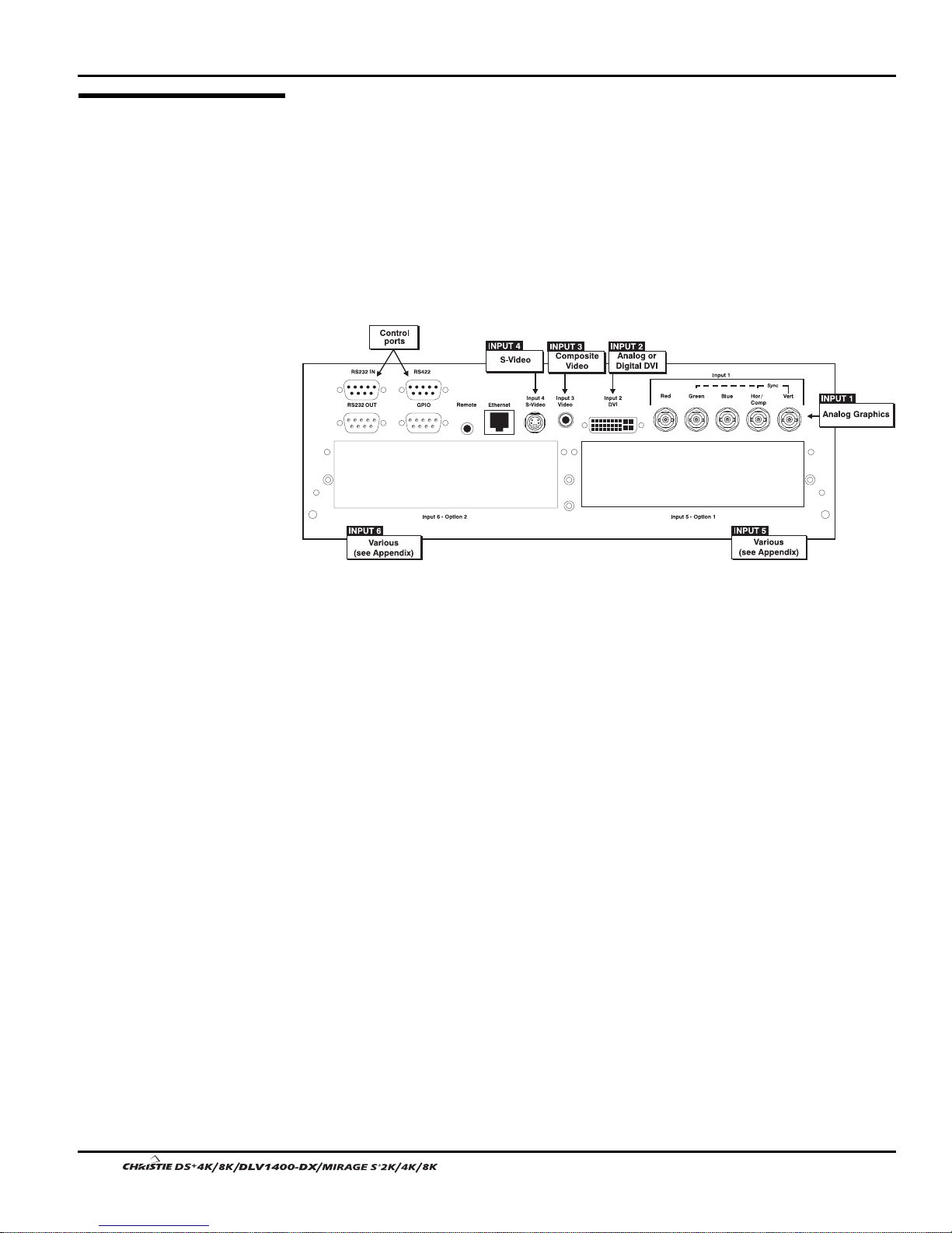
Sources connect to the Input Panel located at the back of the projector. See Figure 2.7.
The upper right corner (
INPUT 1) typically accepts an RGB signal from an external
analog RGB source, or it can also be used for YPbPr signals or additional video
sources. Just beside these BNCs, the DVI-I connector (
analog display signals from a computer. Connect analog composite video at
or S-video at
INPUT 4 from devices such as VCRs, laser disc players or DVD players.
INPUT 2) accepts digital or
INPUT 3
There are also several optional inter face s avai lab le for connec tin g other source s—
these interfaces slide into the remaining unused option slot, and can be done while the
projector is running.
RGB Signals
Figure 2.7. Input Panel
NOTES: 1) See Section 6, Specifications for details regarding compatible inputs. 2)
Use high quality shielded cables only for all connections.
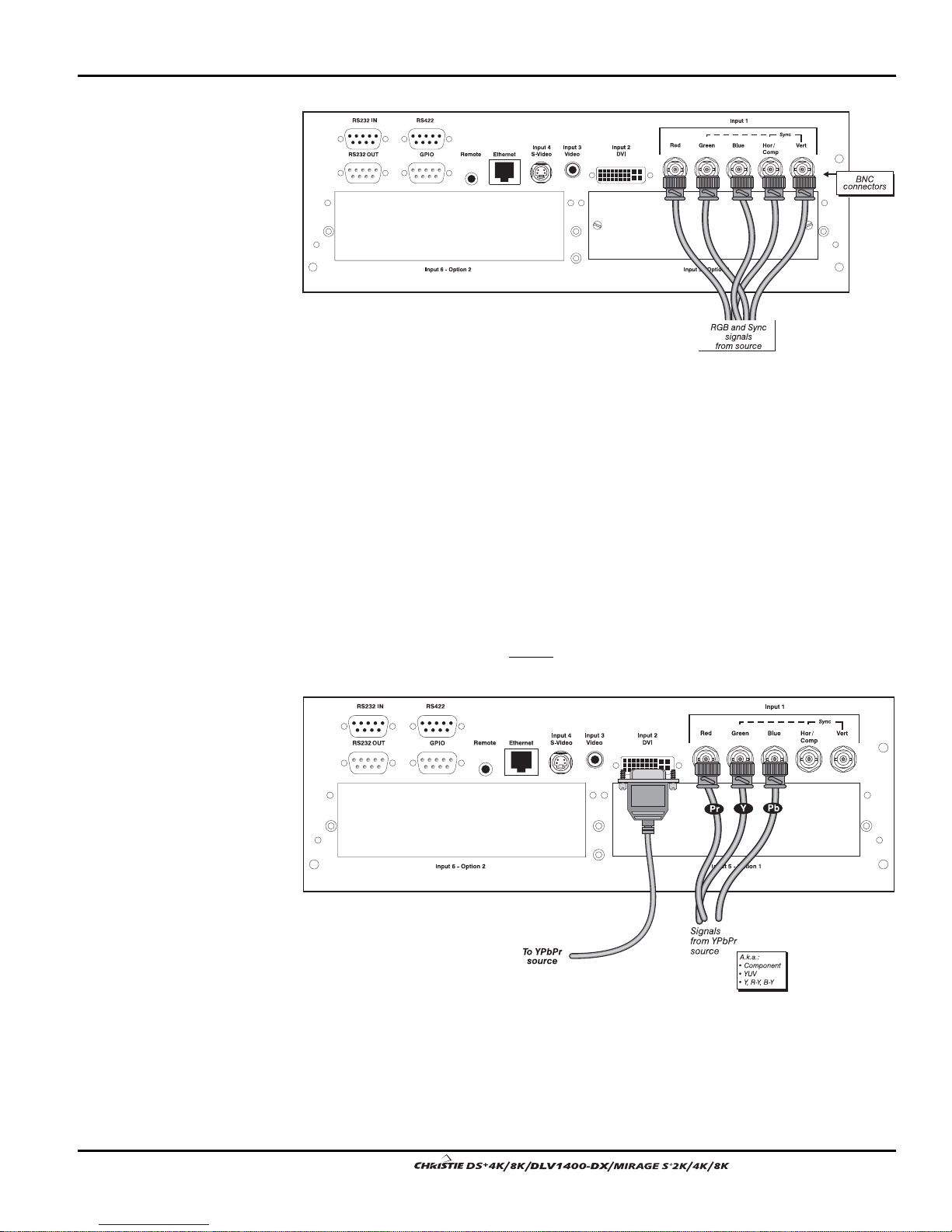
INPUT 1consists of 5 BNCs (connectors) for linking to a variety of sources. The
'
typical connection would be to an RGB source such as a PC, Mac, DEC, Sun, SGI and
others. This projector supports multiple sync types with RGB signals: sync-on-green,
composite sync, and separate H & V syncs.
NOTE: Depending on your source, you may need a custom adapter cable with BNC
connectors at the projector end and a different type of connector at the other (such as
a 15-pin "D" connector for some computer sources). Contact your dealer for details.
Connect the
outputs to the
SYNC BNC input(s) first. Then connect the red, green and blue source
RED, GREEN, and BLUE BNCs on the INPUT 1 panel. If the source uses
sync-on-green, only the red, green, and blue connections are required. If the source
provides a composite sync output, connect it to the
SYNC input labeled HOR/COMP. If
the source provides separate horizontal and vertical sync outputs, connect horizontal
sync to the
labeled
SYNC input labeled HOR/COMP and connect vertical sync to SYNC input
VERT. See Figure 2.8.
2-12
User’s Manual
Section 2: Installation and Setup
Figure 2.8. Connecting RGB and Sync
NOTES: 1) If for some reason the projector fails to recognize a signal as an RGB
signal, specify this Color Space option within the Image Settings menu. See 3.5
Adjusting the Image. 2) To connect YPbPr signals–such as from DVDs or analog HDTV
sources–to
INPUT 1, use the red, green and blue BNCs as described in YPbPr Signals
(below).
YPbPr Signals
(COMPONENT VIDEO)
Connect a YPbPr signal (component vid eo) to INPUT 1 or INPUT 2 as shown in Figure
'
2.9.
NOTES: 1) If, for some reason, the projector fails to recognize a YPbPr signal,
specify this Color Space op tion w ithin the Image Settings menu. See 3.5, Adjusting
the Image. 2) Do not connect digital
1
. Install an appropriate optional module in INPUT 5 or INPUT 6 for this.
component signals (known as YCbCr) to INPUT
Figure 2.9. Connecting YPbPr sources
User’s Manual 2-13.
Section 2: Installation and Setup
p
p
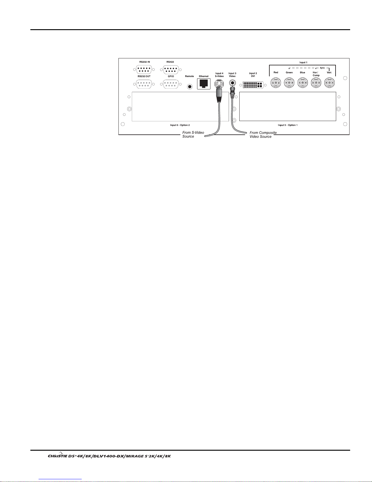
Com
osite and S-Video '
DVI Digital Video '
INPUT 3 and INPUT 4 provide simultaneous connection of both a composite video
source (
INPUT 3) and an S-Video source (INPUT 4). See Figure 2.10.
Figure 2.10.Connecting Composite or S-Video sources
Use the DVI-I connector at INPUT 2 to connect either analog or digital video devices
to the projector. When connecting devices that transmit an analog video signal such as
VCRs, laptops, and PCs use the DVI cable provided with the projector. Plug the
DVI-I (single link) connector end to the projector and the 15-pin VGA connector to
the device.
Use a cable with DVI-I connectors at both ends to connect devices that transmit
digital and analog video signals such as high-quality DVD players, satellite receiver
and digital cable TVs.
O
tional Inputs '
NOTE: 1) To ensure true digital output from devices that transmit digital signals,
connect to the DVI-I connector. 2) DVI loop through is not available unless you have
the optional DVI Input Module installed at
INPUT 5 or INPUT 6.
Optional modules allow you to increase your total number of inputs and/or
accommodate different signal types, whether analog or digital. Install in the areas
labeled
INPUT 5 or INPUT 6. Options include:
• RGB 500 Input Module
• RGB 400 Active Loop Thru Input Module
• RGB 400 Buffered Amplifier Input Module
• Composite/S-Video Input Module
(not supported in v1.0 software)
• PC250 Analog Input Module
• Serial Digital Input Module
• DVI Input Module
• Dual SD/HD-SDI Module
(available 2005)
NOTES: See Appendix F, Optional Input Modules for a brief description of each
interface.
2-14
User’s Manual
2.4 Connecting
Communications
As an alternative to the projector’s keypad or remote, you may wish to communicate
with the projector using a PC or other controller. Such a device sends commands and
receives feedback via serial links (RS232 and RS422), Ethernet or GPIO
communications to the projector, all described below.
Section 2: Installation and Setup
Remote Keypads '
Serial Port Connections '
As desired, direct the projector’s IR remote keypad towards the display screen or the
projector’s IR sensors. Alternatively, connect a wired (tethered) ver sion of the rem ote
to the 3.5mm RCA jack labeled as
REMOTE on the projector’s input panel. Note that
response to a wired keypad must also be enabled in the Communications menu—see
3.6, Adjusting System Parameters and Advanced Controls for more information.
There are two types of serial ports available on the projector: RS232 and RS422. You
can connect a device with a serial interface, such as a computer to either of these
connectors (not both) and control the projector remotely by entering specific serial
communication commands.
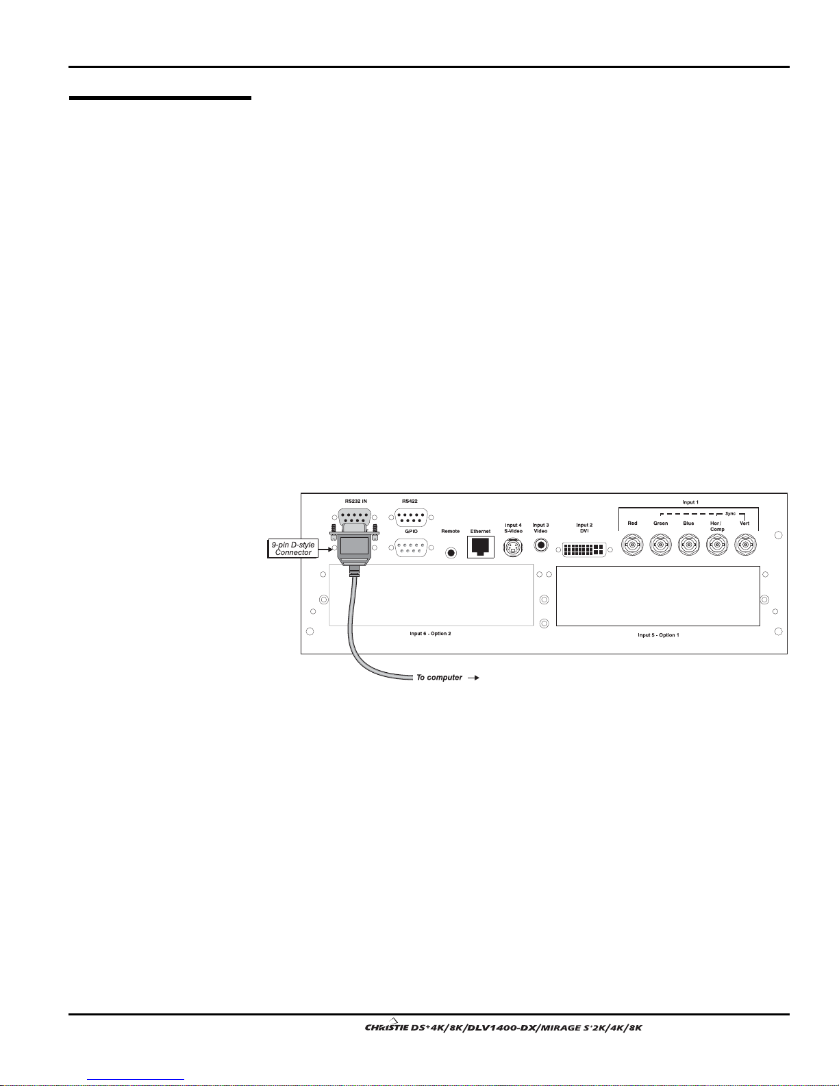
Connecting RS-232
The two 9-pin DIN connectors labeled RS232 IN and RS232 OUT on the input panel
are dedicated to serial communication. Using the appropriate serial communication
cables (see Appendix C) connect the controlling source, such as a personal computer
to the RS232 IN connector. Then set the baud rate to match that of the computer.
Refer to Section 3 for details on changing the projector’s baud rate.
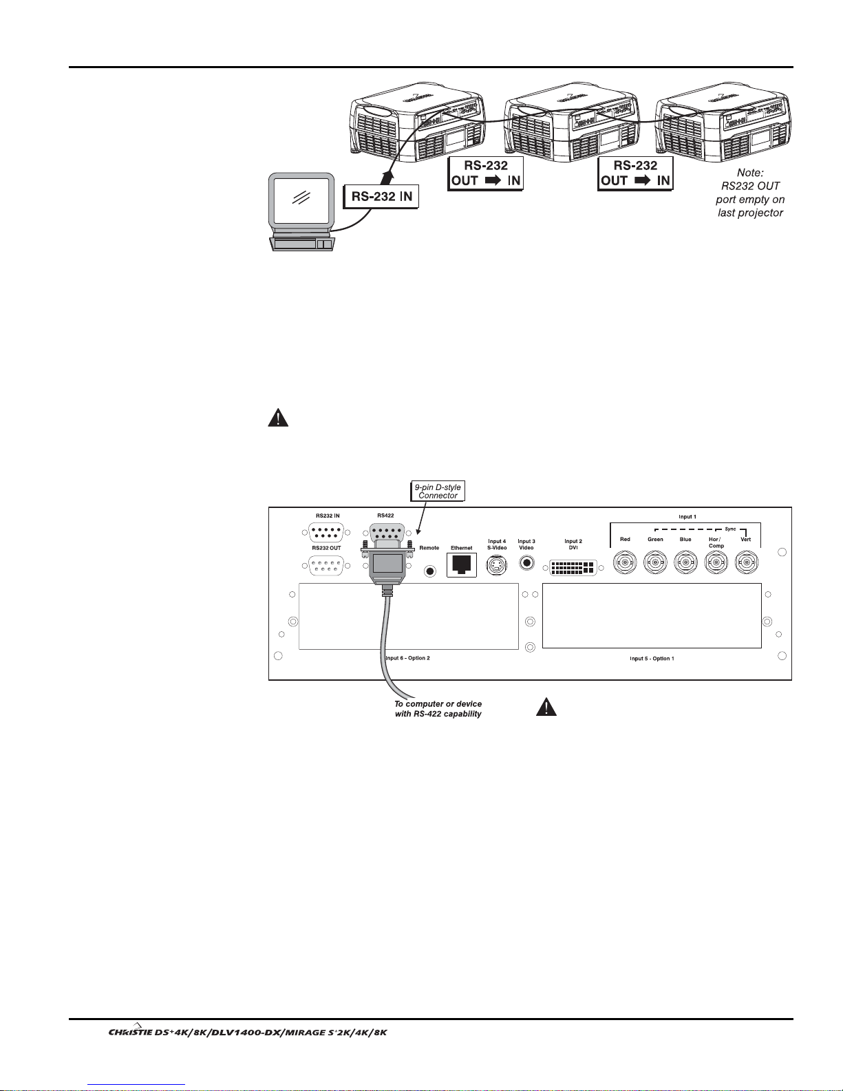
If you want to connect multiple projectors in a network with serial communication,
connect the controlling source to the RS232 IN connector of the first projector in the
network. Then take another serial communication cable and connect one end to the
RS232 OUT connector and the other end to the RS232 IN connector of the next
projector. Continue this pattern of connection with all projectors in the netwo rk. The
last projector in the network will only have a connection to the RS232 IN connector.
Figure 2.11. Connecting RS232
User’s Manual 2-15.
Section 2: Installation and Setup
Figure 2.12. RS232 Network
Connecting RS-422
If you wish to control the projector with a computer and or other controlling device
with RS-422 capability, connect a RS-422 serial communication cable between the
computer and the RS-422 port on the projector. RS-422 is better suited for serial
communication over long distances then is RS-232 communication.
Use the RS-422 port only if your device had RS-422 capability – always consult
the literature provided with your equipment before connecting. Connecting to the RS422 port with incompatible equipment could damage your projector.
Ethernet Communications
'
Ethernet Communications
To add the projector to an existing Ethernet network with other equipment such as
controllers and other projectors, connect standard CAT5 Ethernet cable between your
Ethernet controller (or hub) and the Ethernet port on the side of the projector.
Upon connection to an Ethernet network, the projector’s factory default IP address of
0.0.0.0.0 will automatically enable the DHCP function (if available on the network) to
assign a new IP address that is valid and unique for that network. Or, if there is no
DHCP function available on the network (or if a specific static IP address for the
projector is preferred or required), you can set the address in the Ethernet Settings
menu or via an ASCII serial command.
2-16
Figure 2.13. Connecting RS422
User’s Manual
Connect a RS422
device only.

Regardless of how it is assigned, once a projector has a valid and unique address it
will respond to commands sent to this address. To determine the projector’s current IP
address, consult the Status or Communications menus.
Refer to Section 3 for further information about setting up and using a projector
connected via Ethernet.
Log on to www.christiedigital.com for detailed information on ChristieNET.
General Purpose Input Output
2.5 System
Integration -
The GPIO connector on the input panel can be used to provide a method of interfacing
a wide range of external I/O devices to the projector.
GPIO Connector
Refer to Appendix E: System Integration for complete details on pin configuration
and how to program the various pins on the connector.
Section 2: Installation and Setup
2.6 Power
Connection
Plug the line cord to the AC receptacle located at the back of the projector, below the
input panel, and the 3-pronged end into a grounded AC outlet. The input voltage to the
projector must be capable of 100 – 240 VAC in 500W and 1000W models and 200-
240VAC in 1200W models. (See also Section 6 – Specifications for complet e details
on all power requirements.)
Use the approved North American-rated line cord supplied with the projector. If you
are connecting to an area outside of North America make sure you are using an
appropriately rated line cord.
Always power down the projector before unplugging the AC line cord. Wait 5-10
minutes for the main exhaust fan to turn off and for the lamp to cool sufficiently
before unplugging the projector.
WARNINGS
Do not attempt operation if the AC supply and cord are
not within the specified voltage and power range.
Wait for the cooling fans to turn off before unplugging the
projector.
User’s Manual 2-17.

Section 3
A
Adj
Operation
This section explains how to effectively operate the projector once it has been
installed. It is recommended that you read this section and familiarize yourself with
the components and the available menu options before you begin using your projector
for the first time.
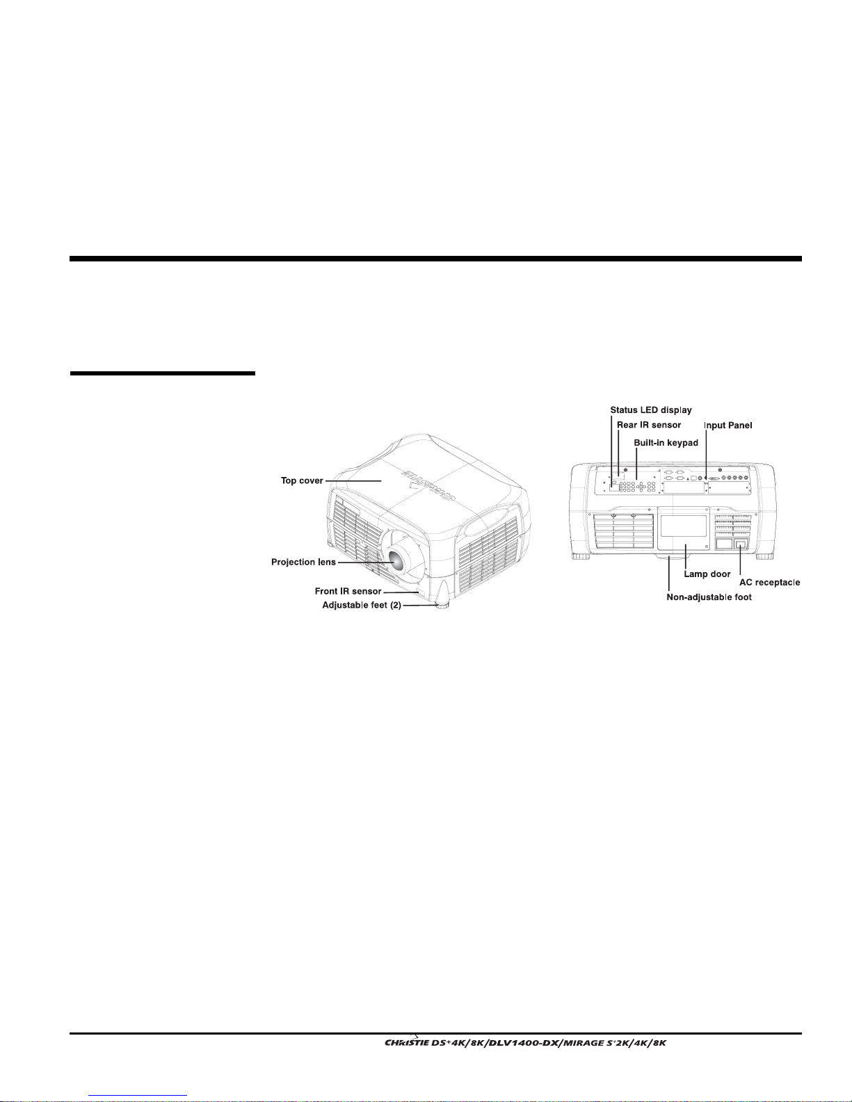
3.1 About the
Projector
Built-in Keypad '
C Receptacle '
Figure 3.1. Projector Basics
The built-in keypad is located at the back of the projector, beside the input panel. Use
it similarly to the IR remote to control the projector. A status LED display is also
included on this keypad for monitoring projector status.
The AC receptacle is located at the back of the projector just below the input panel.
Use this outlet to plug in an appropriately rated line cord. Refer to Section 6 –
Specifications for details.
ustable Feet '
Located on the underside of the projector are two fully adjustable feet. Raise or lower
these feet when positioning the projector to ensure it is level on all sides so the
displayed image will appear rectangular without any keystone. NOTE: The third foot,
located at the rear of the projector (underside) is not adjustable.
Refer to Section 2 - Projector Position and Mounting for instructions on how to adjust
the projector’s feet.
User’s Manual 3-1

Section 3: Operation
j
Lens Mount &
Pro
ection Lenses '
The projector is built with a motorized lens mount that allows for easy lens control
and adjustment. This includes such functions as adjusting vertical and horizontal
offsets, zoom and focus. The lens mount can be fitted with any one of the available
optional lenses – see Section 6 - Specifications.
• Zoom and Focus – There are two internal lens motors that allow for quick
motorized adjustment of zoom and focus. Adjust zoom to fit the displayed
image on the screen and adjust focus to improve the clarity of the image.
NOTE: You can manually override zoom and focus adjustments set with the
remote. Turn the outer ring on the projection lens to adjust focus and the
inner ring to adjust zoom.
• Lens Offset – Vertical and horizontal offset is performed on the lens mount
through the use of DC motors.
• Shutter – Standard on all models the shutter allows you to turn the screen
absolutely black when in the “on” state.
• Optical Aperture – Enables adjustment of light output and contrast ratio.
NOTES: 1) The projection lens is shipped separately from the projector. 2) Use the
lens cap when transporting the projector to avoid scratching and damaging the lens,
which could affect your displayed image.
Input Panel '
Cooling and Air Vents '
Front & Rear IR Sensors '
Lamp Door '
All source connections are made to the input panel located at the back of the projector.
Connect RGB or YPbPr sources to
2
, composite video to INPUT 3, and S-video to INPUT 4. Any of the available optional
modules can be installed in
INPUT 5 and/or INPUT 6.
INPUT 1, analog or digital display signals to INPUT
There is no status display on the input panel. The only status display is part of the
built-in keypad located at the rear of the projector.
There are numerous air vents located around the projector. It is important these vents
remain unobstructed. Adequate airflow through the projector will prevent it from
overheating.
The two IR sensors located on the projector receive transmissions from the IR remote
from up to 100 feet away. It is important to keep the transmission path to these sensors
unobstructed for uninterrupted communications with the projector. The front IR
sensor is located next to the projector’s nameplate and the rear IR sensor is located at
the back of the projector just above the status LED display.
The lamp door is located at the back of the projector, which provides easy access to
the lamp module for replacement. See Section 4 for lamp replacement procedures.
3-2
User’s Manual
Section 3: Operation
3.2 Using the
Remote or Built In Keypad
Keypad Commands '
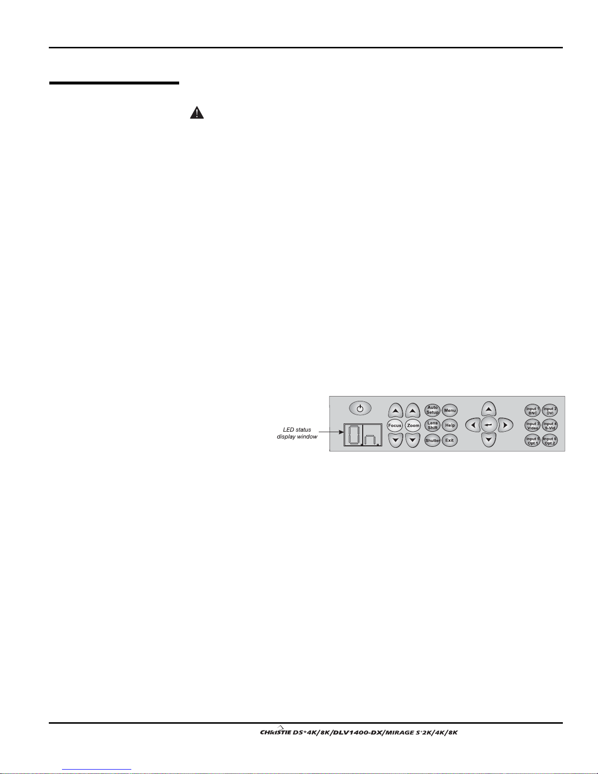
Built-in '
Laser radiation is emitted from the laser diode in the remote. Do not look
directly into the beam of the remote.
The projector is typically controlled using one of the following keypads:
• Built-in Keypad located at the back of the projector
• Remote Keypad for tethered or tetherless control up to 100 feet away
(includes cable for use as a wired remote)
While each of the keypads provides complete con tro l of th e pro jecto r, they differ
slightly in their arrangement of keys and in what functions can be accessed directly
with a key press rather than requiring use of the menu system. You may find one
keypad more convenient than another for your specific installation and application.
NOTE: This keypad has a single IR protocol and can be converted to a wired remote
by connecting the cable provided with the projector to the RCA jack labeled as
REMOTE on the input panel.
To control the projector when signals from a remote keypad cannot reach the
projector, use the projector’s built-in keypad. The nearby LED display provides
feedback indicating current status and activities of the projector. Because the built-in
keypad has fewer
keys than the
remote keypad,
certain projector
functions are
accessible only
through the menu
Figure 3.2. Built-in Keypad
system rather
than via a direct key.
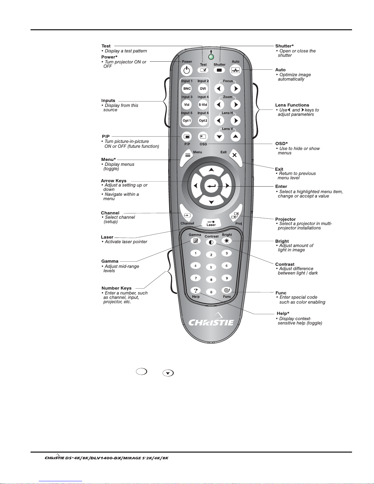
Refer to the key descriptions provided for the IR remote – see Figure 3.3.
IR Remote '
The IR remote keypad controls the projector by way of wireless communications from
a battery-powered infrared (IR) transmitter. Use the IR remote keypad the same way
you would use a remote keypad supplied with a TV or VCR. When making key
presses, direct the keypad either toward the screen or toward the front or rear of the
projector. One of the two IR sensors on the projector will detect the signals and relay
the commands for internal processing.
User’s Manual 3-3.
Section 3: Operation
* These are toggle keys, which require you to press and hold or press twice or
press and use the up/down arrow keys. NOTE: To turn the OSD off you must
press
3-4
OSD
and .
Figure 3.3. Remote Keypad
User’s Manual
Wired Remote
You can convert the IR remote into a wired remote keypad using the cable provided
'
with the projector. Connect one end into the remote and the other to the mini stereo
connector on the input panel labeled as
when:
• the built-in keypad is inaccessible
• the lighting conditions are unsuitab le for prop er IR transmission
NOTE: Leave the batteries in the wired remote for the laser key (
Guide to Keypads '
Keep in mind the following guidelines:
• Press keys one-at-a-time; there are no simultaneous key combinations required.
• Note that three keys—Power
hold” keys that do not function with a typical quick press-and-release key press.
• Hold arrow keys down for continuous adjustment/movement in one direction. In
serial networks, pause briefly between adjustments to ensure that more distant
projectors can “keep up” with the commands.
• If you press a key while the projector is still responding to the previous action,
such as during power-up, the second key press may not take effect.
Section 3: Operation
REMOTE. The wired remote is recommended
) to work.
, Shutter
Shutter
and OSD
OSD
—are “press-and-
Keypad Commands '
Test
Auto
Specific keypad commands are explained below:
Power ON/OFF
Press and hold
keystroke. Or press and release
for two seconds to toggle the projector on or off with a single
followed immediately by
(on) or
(off)
to guarantee the correct toggle (useful if you are unsure of the present state).
NOTES: 1) After powering down, the lamp cooling fan remains on for approximately
5 minutes to cool the lamp. 2) It is a good idea to avoid turning a projector back on
until it has been off for a few minutes. Hot re-strikes of the lamp may reduce lamp life.
Test
Test
Press
input. If you press
to step forward through all internal test patterns and eventually the current
Test
and then cycle by using the and right arrow keys,
you’ll be cycling in either direction through the test patterns only, no input.
Auto
Auto
Press
to initiate an automated process in which the projector optimizes critical
display parameters such as size, position, pixel tracking, etc., for the current source.
These parameters are listed in
Table 3.1. An Auto Setup can save time in perfecting a display and you can modify the
adjustments as desired.
User’s Manual 3-5.
Section 3: Operation
Table 3.1. Auto Setup
What an “Auto Setup” Does
OPTIMIZES: SETS TO DEFAULT:
Pixel Tracking Contrast
Pixel Phase Brightness
Size and Blanking Auto Input Level (off)
Vertical Stretch Detail (if video source)
Position Filter
Input Levels Luma Delay
NOTE: You must have an unlocked channel present to use Auto Setup.
Chan nel
Channel
Chan nel
Press
to select a specific source setup (channel) defined and stored in projector
memory. Once you enter a 2-digit channel number (or, if there is a list displayed,
highlight it and press
), the display will automatically change and update
according to the numerous setup parameters defined for that channel. Note that a new
channel is automatically created if you adjust an image from a new source.
NOTE: Channel (
Chan nel
) key behavior during a presentation depends on whether or not
the Display Channel List o ptio n is enabled in the Menu Preferences menu. You can
Chan nel
choose to use a scrollable list of channels when you press
, or you may prefer to
enter the desired channel number “blind”, i.e., without on-screen feedback. See Menu
Preferences later in this section.
Input 1
Input 2
Input 3
Input 1
Input 1
Press
Input 2
Input 2
Press
Input 3
Input 3
Press
to display from the data input source connected to BNCs labeled
to display from the DVI source connected to INPUT 2.
to display from the composite video source connected to INPUT 3.
INPUT 1.
Input 4
Input 4
Press
Input 5
Input 5
Press
NOTE: If you have the optional Dual SD/HD-SDI Module installed and there are two
inputs connected here, the second input (B) is considered
built-in keypad or the
remote keypad, press
3-6
Input 4
to display from the S-video source connected to INPUT 4.
Input 5
to display from the INPUT 5 interface module installed in the Option 1 slot.
INPUT 7. If you are using the
INPUT 5 to access INPUT 7 as follows:
• While displaying from
INPUT 5, press
Input 5
again. This switches to INPUT 7.
• While displaying from any input other than the Dual SD/HD-SDI Module,
Input 5
press
the Dual SD/HD-SDI Module inputs (A or B) was last used. Press
. This switches to either INPUT 5 or INPUT 7, depending on which of
Input 5
again to
display from the other Dual SD/HD-SDI Module input.
User’s Manual
Section 3: Operation
Input 6
Input 6
Input 6
Press
to display from the INPUT 6 interface module installed in the Option 2 slot.
NOTE: If you have the optional Dual SD/HD-SDI Module installed and there are two
inputs connected here, the second input (B) is considered
built-in keypad or the remote keypad, press
INPUT 6 to access INPUT 8 as follows:
INPUT 8. If you are using the
• While displaying from
INPUT 6, press
Input 5
again. This switches to INPUT 8.
• While displaying from any input other than the Dual SD/HD-SDI Module,
Input 5
press
the Dual SD/HD-SDI Module inputs (A or B) was last used. Press
. This switches to either INPUT 5 or INPUT 8, depending on which of
Input 5
again
to display from the other Dual SD/HD-SDI Module input.
Contrast
Contrast
Contrast
Press
to change the amount of white in your images. Use keys until
you reach the desired level of contrast—for best results, start low and increase so that
whites remain bright but are not distorted or tinted and that light areas do not become
white (i.e., “crushed”). Conversely, low contrast causes dim images. See 3.5,
Adjusting the Image (Image Settings subsection).
Bright
Brightness
Bright
Press
to increase or decrease the amount of black in the image. Use
keys until you reach the desired level of contrast—for best results, start high and
decrease so that dark areas do not become black (i.e., “crushed”). Conversely, overly
high brightness changes black to dark gray, causing washed-out images. See 3.5,
Adjusting the Image (Image Settings subsection).
Gamma
Gamma
“Gamma” determines how gray shades are displayed between minimum input (black)
and maximum input (white) for a given amount of signal. Th e proper se tt ing help s
maintain optimized blacks and whites while ensuring a smooth transition for the “inbetween” values utilized in grays. Unlike brightness and contrast controls, the overall
tone of an image can be lightened or darkened without changing the two extremes and
your images will be more vibrant yet with good detail in dark areas when using the
Gamma control.
The normal gamma setting of 2.2 is correct for most signals and conditions. If excess
ambient light washes out the image and it becomes difficult or impossible to see
details in dark areas, lower the gamma setting to compensate. This will improve
contrast ratio while maintaining good details for blacks and whites
Menu
Menu
Press
Menu
to enter or exit the projector’s menu system.
User’s Manual 3-7.

Section 3: Operation
OSD
OSD (On-screen display)
Press
OSD
to hide the projector’s menu system during use. To see the menus
again, do one of the following:
• Press and hold
• Press and release
• Press
OSD OSD
OSD
for two seconds
OSD
followed immediately by
Invisible menus are fully functional, enabling “hidden” access to numbered features
and image adjustments by entering the corresponding sequence of keypresses on the
keypad.
NOTES: 1) With OSD “on”, you can still hide error messages and slidebars by
disabling these options in the Menu Preferences menu.
Shutter
Shutter
Shutter
Press and hold
for two seconds to toggle the internal mechanical shutter blade
closed or open with a single keystroke. Or press and release
immediately by
you are unsure of the present state). Alternatively, press
(closed) or
(open) to guarantee the correct toggle (useful if
Shutter Shutter
Shutter
followed
to toggle from the
present on/off state. A closed shutter blanks the display (turns it to black). Close the
shutter to mute all display while maintaining access to projector functions. Opening
the shutter restores the image.
NOTES: 1) “Sh” appears in the LED display when the shutter is closed
. 2) The
shutter is open upon power-up.
Func
Function Key
IF WITHIN A MENU: Using the
Func
for special tasks within the menu system is noted
with the appropriate topic elsewhere in Section 3. For example, press
Func
in the
Channel Setup menu to enable deletion or copying of a channel.
IF WITHIN A PRESENTATION: Press
Func
followed by a 2-
digit number to enable a specific color or colors in the
display (see right). For example,
Func
only red and green data,
67
64
will display all color
will display
Func
data. Eliminating one or more colors can help with certain
diagnostics and setups, such as when accurately overlaying
one image on top of another from stacked projectors.
NOTE: Color enabling can also be implemen te d from numerous locations within the
menu system.
Proj
Projector
Press
Proj
to access a specific projector within a group of projectors or to confirm if
the local projector is listening. The number in the “Enter Number” window indicates
which projector is currently listening to commands, and will match the projector
number that has been defined in the Menu Preferences menu.
The “Projector” checkbox (read-only) shows whether or not the projector physically
connected to a keypad is listening to commands from that keypad. A checkmark
3-8
User’s Manual
 Loading...